

Page 1

Getting Started Guide Getting Started Guide Getting Started Guide
Quantum Scalar i500 Tape Library
Quantum Scalar i500 Tape Library
Scalar i500
6-01741-01
Page 2

Scalar i500 Getting Started Guide, 6-01741-01, Ver. A, June 2007, Made in USA.
Quantum Corporation provides this publication “as is” without warranty of any kind, either express or implied, including but not
limited to the implied warranties of merchantability or fitness for a particular purpose. Quantum Corporation may revise this
publication from time to time without notice.
COPYRIGHT STATEMENT
Copyright 2007 by Quantum Corporation. All rights reserved.
Your right to copy this manual is limited by copyright law. Making copies or adaptations without prior written authorization of
Quantum Corporation is prohibited by law and constitutes a punishable violation of the law.
TRADEMARK STATEMENT
Quantum, the Quantum logo, DLT, DLTtape, the DLTtape logo, and Scalar are all registered trademarks of Quantum Corporation. LTO
and Ultrium are trademarks of HP, IBM, and Quantum in the USA and other countries.
All other trademarks are the property of their respective companies.
Page 3

Table of Contents
Scalar i500 Getting Started Guide (English) . . . . . . . . . . . . . . . . . . . . . . . . . . . . . . . . . .5
Scalar i500 - Einführungshandbuch (German). . . . . . . . . . . . . . . . . . . . . . . . . . . . . . . .23
Guide de démarrage rapide de la bandothèque Scalar i500 (French). . . . . . . . . . . . . .41
Guía de inicio de Scalar i500 (Spanish). . . . . . . . . . . . . . . . . . . . . . . . . . . . . . . . . . . . .59
Руководство по началу работы с ленточной библиотекой Scalar i500
(Russian) . . . . . . . . . . . . . . . . . . . . . . . . . . . . . . . . . . . . . . . . . . . . . . . . . . . . . . . . . . . .77
Scalar i500 スタート ガイド (Japanese) . . . . . . . . . . . . . . . . . . . . . . . . . . . . . . . . . . . .95
Scalar i500 시작 설명서 (Korean) . . . . . . . . . . . . . . . . . . . . . . . . . . . . . . . . . . . . . . . .113
Scalar i500 入门指南 (Simplified Chinese). . . . . . . . . . . . . . . . . . . . . . . . . . . . . . . . . .131
Scalar i500 Getting Started Guide 3
Page 4

4 Scalar i500 Getting Started Guide
Page 5

Scalar i500 Getting Started Guide
The Scalar i500 Getting Started Guide provides an overview of the steps required to unpack, set up, and
install the Scalar i500 library. For more detailed information on configuring and running your library as well
as adding, removing, and replacing parts, see the Scalar i500 User’s Guide.
Release Notes are also available for this product. The Release Notes describe changes to your system or
firmware since the last release, provide compatibility information, and discuss any known issues and
workarounds.The Release Notes can be found at www.quantum.com
documentation in “About This Guide and Your Product” in the Scalar i500 User’s Guide.
. You can find a list of additional
Note
WARNING
WARNING
WARNING
Before operating this product, read all instructions and warnings in this document and
in the System, Safety, and Regulatory Information Guide. In addition, be sure to use
this document in conjunction with the Scalar i500 User’s Guide.
WITHOUT TAPE DRIVES, TAPE CARTRIDGES, OR POWER
SUPPLIES, A 5U CONTROL MODULE WEIGHS APPROXIMATELY 58
LBS. A 9U EXPANSION MODULE, WITHOUT TAPE DRIVES, TAPE
CARTRIDGES, OR POWER SUPPLIES, EXCEEDS 65 LBS. TO AVOID
SERIOUS INJURY, TWO PEOPLE ARE REQUIRED TO SAFELY LIFT
THE MODULES INTO POSITION.
THE POWER OUTLET MUST BE AVAILABLE NEAR THE LIBRARY
AND MUST BE EASILY ACCESSIBLE.
ALL LIBRARIES TALLER THAN 14U MUST BE INSTALLED IN A RACK
HAVING A MAIN PROTECTIVE EARTHING (GROUNDING) TERMINAL,
AND POWER MUST BE SUPPLIED VIA AN INDUSTRIAL PLUG AND
SOCKET-OUTLET AND/OR AN APPLIANCE COUPLER COMPLYING
WITH IEC 60309 (OR AN EQUIVALENT NATIONAL STANDARD) AND
HAVING A PROTECTIVE EARTH (GROUND) CONDUCTOR WITH A
CROSS SECTIONAL AREA OF AT LEAST 1.5 MM
2
(14 AWG).
TO ENSURE PROPER AIRFLOW AND ACCESS SPACE, ALLOW 60 CM
(24 INCHES) IN THE FRONT AND BACK OF THE LIBRARY.
WARNING
Scalar i500 Getting Started Guide 5
UNDER NO CIRCUMSTANCES SHOULD A RACK BE MOVED WHILE
LOADED WITH ONE OR MORE MODULES.
Page 6

Step 1: Unpack the Library
1 Unpack the library.
Following the unpacking instructions that came with the library, remove the library exterior packaging
but leave the library in the bottom packaging tray.
CAUTION
2 Check the contents of the package against the packing slip.
3 Remove the interior packaging.
CAUTION
WARNING
4 Remove the tape drives from the library.
For information about removing tape drives, see “Adding, Removing, and Replacing” in the Scalar i500
User’s Guide.
Save all packing materials in case you need to move or ship the
library in the future.
Be sure to remove the following items:
• The strap holding the robot in place. Release the velcro and unhook
each end of the strap.
• All cardboard and foam surrounding the robot.
WITHOUT TAPE DRIVES, TAPE CARTRIDGES, OR POWER
SUPPLIES, A 5U CONTROL MODULE WEIGHS APPROXIMATELY 58
LBS. A 9U EXPANSION MODULE, WITHOUT TAPE DRIVES, TAPE
CARTRIDGES, OR POWER SUPPLIES, EXCEEDS 65 LBS. TO AVOID
SERIOUS INJURY, TWO PEOPLE ARE REQUIRED TO SAFELY LIFT
THE MODULES INTO POSITION.
5 Remove the power supplies from the library.
For information about removing power supplies, see “Adding, Removing, and Replacing” in the Scalar
i500 User’s Guide.
6 Choose an optimal location for the library.
To avoid damage, the library must be positioned in a stable location. See the System, Safety, and
Regulatory Information Guide for more information on finding an optimal location for your library.
WARNING
• Make sure a power source (only of the type marked on the product label) is available. For power
requirements, see the ”Specifications” chapter in the Scalar i500 User’s Guide.
• Route any cables to avoid walking on them or pinching them with items placed on or against them.
Pay particular attention to the cord at the wall receptacle and the point where the cord exits from
the library. For recommended cabling procedures, see the Scalar i500 User’s Guide.
• Make sure that objects will not fall and liquids will not spill into the library’s chassis through
openings.
THE POWER OUTLET MUST BE AVAILABLE NEAR THE LIBRARY
AND MUST BE EASILY ACCESSIBLE.
6 Scalar i500 Getting Started Guide
Page 7
Step 2: Install the Rackmount Kit (Optional for 5U and 14U)
All Scalar i500 libraries taller than 14U must be installed in a rack.The rack secures the bottom module, and
all other modules are then secured to the bottom module. Installing the modules into the rack requires at
least two people. For instructions, see “Installing the Rackmount Kit” in the Scalar i500 User’s Guide.
Step 3: Install the Module(s)
There are two possible library configurations:
• Installing the Control Module as a Standalone Unit
• Installing a Multi-Module Library Configuration
Installing the Control Module as a Standalone Unit
1 Open the library’s I/E station door and access door.
2 Lift the control module and place it in the desired location.
3 If you are placing the control module in a rack, use the rack ears to fasten the control module to the rack.
For instructions, see “Installing the Rackmount Kit” in the Scalar i500 User’s Guide.
4 Continue installation with Step 4: Install the Module Components
on page 13.
Installing a Multi-Module Library Configuration
Follow these instructions if you are installing a new multi-module library, or if you are adding expansion
modules to an existing library.
Required tools:
• Phillips #2 screwdriver, for removing and replacing the top cover plate
• T10 TORX screwdriver, for removing and replacing the bottom cover plate
There are no restrictions on where the control module can be installed in the library configuration. However,
the recommended placement of the control module for library configurations up to 32U is on top of all
installed 9U expansion modules. The recommended placement of the control module for 41U library
configurations is on top of three 9U expansion modules and below the top expansion module.
Cover Plate
Cover Plate Expansion Module
Cover Plate CONTROL MODULE CONTROL MODULE
Cover Plate CONTROL MODULE Expansion Module Expansion Module
Cover Plate CONTROL MODULE Expansion Module Expansion Module Expansion Module
CONTROL MODULE Expansion Module Expansion Module Expansion Module Expansion Module
Cover Plate Cover Plate Cover Plate Cover Plate Cover Plate
5U 14U 23U 32U 41U
Scalar i500 Getting Started Guide 7
Page 8
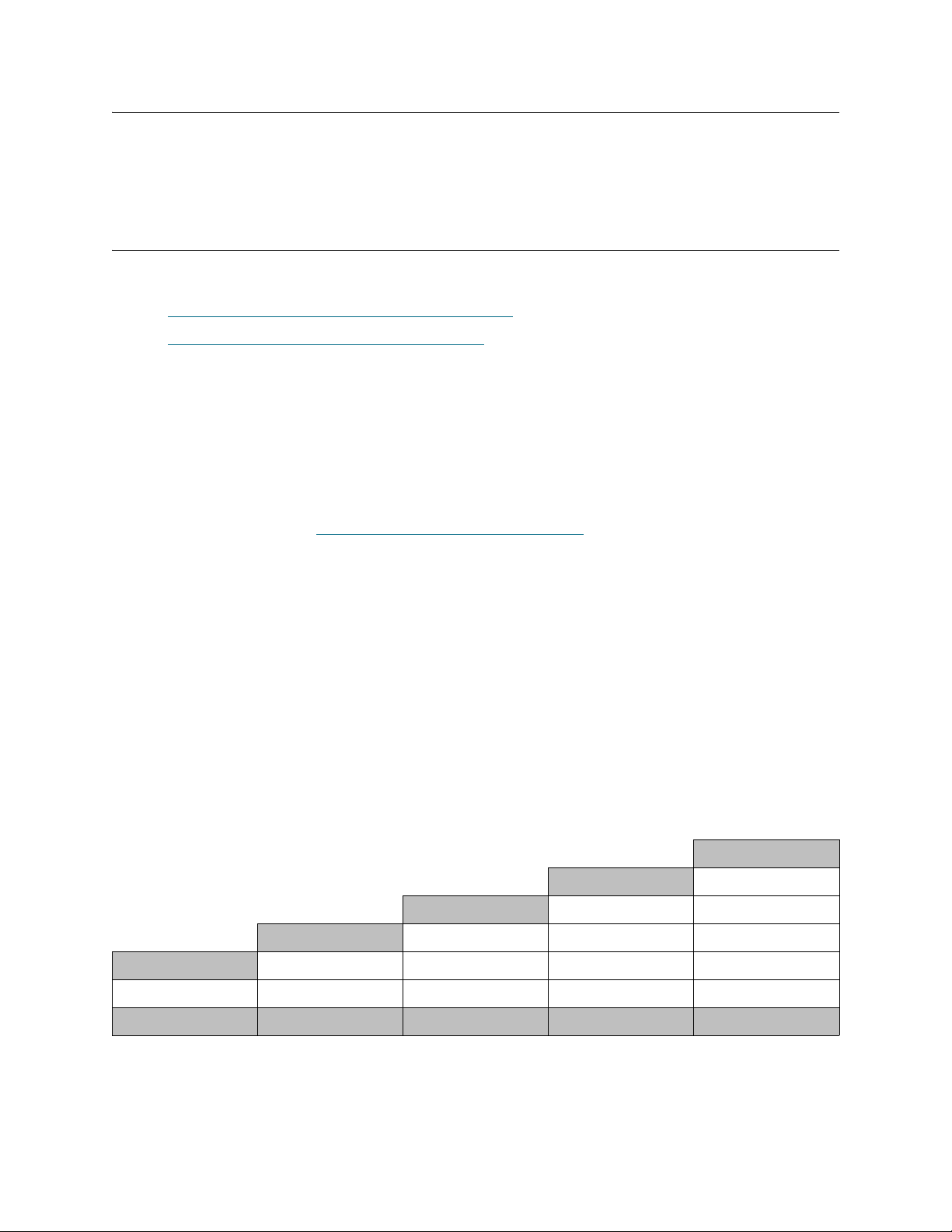
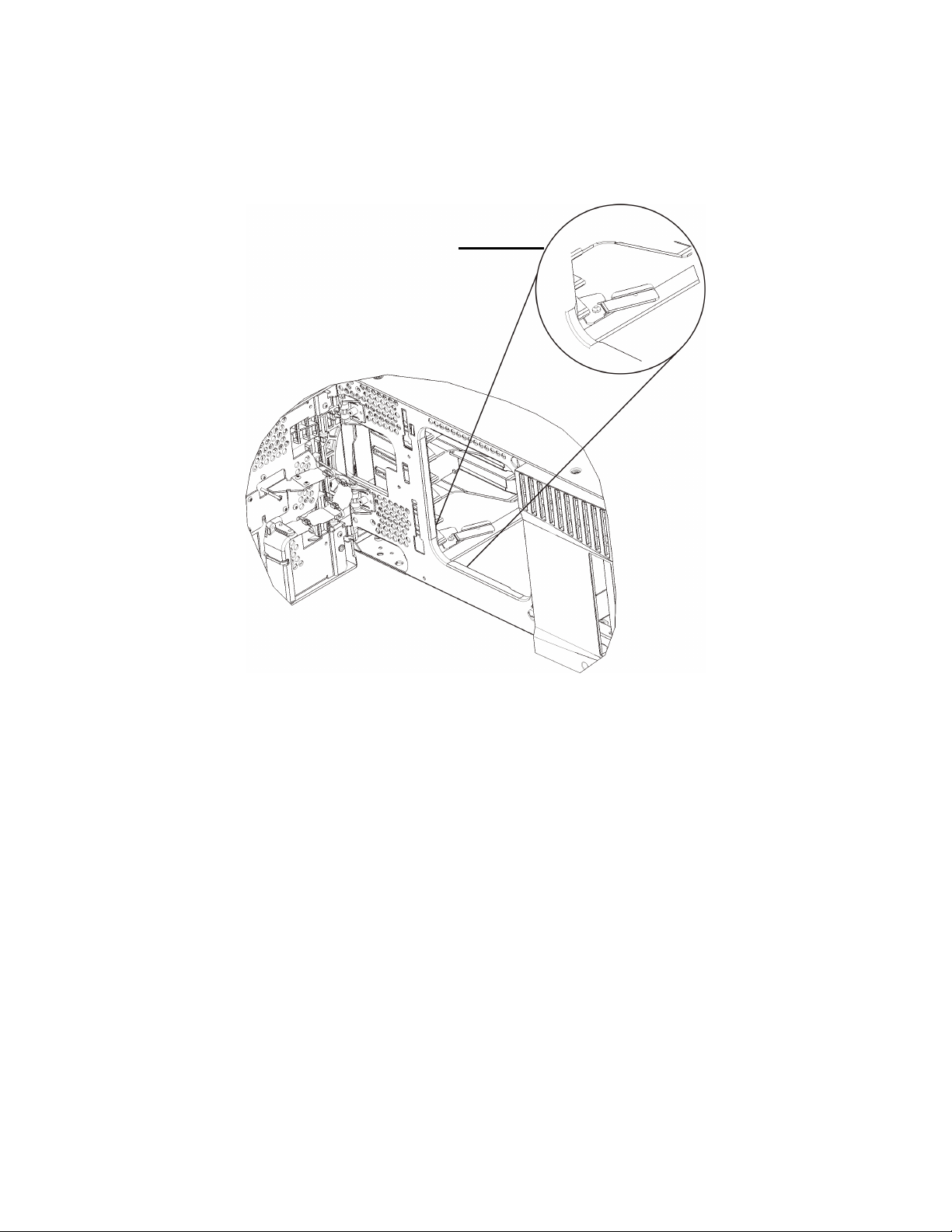
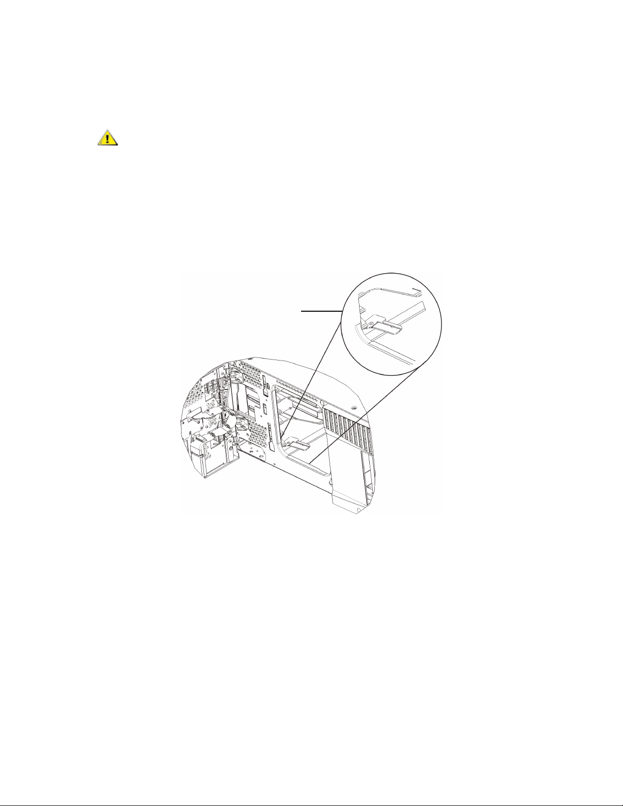
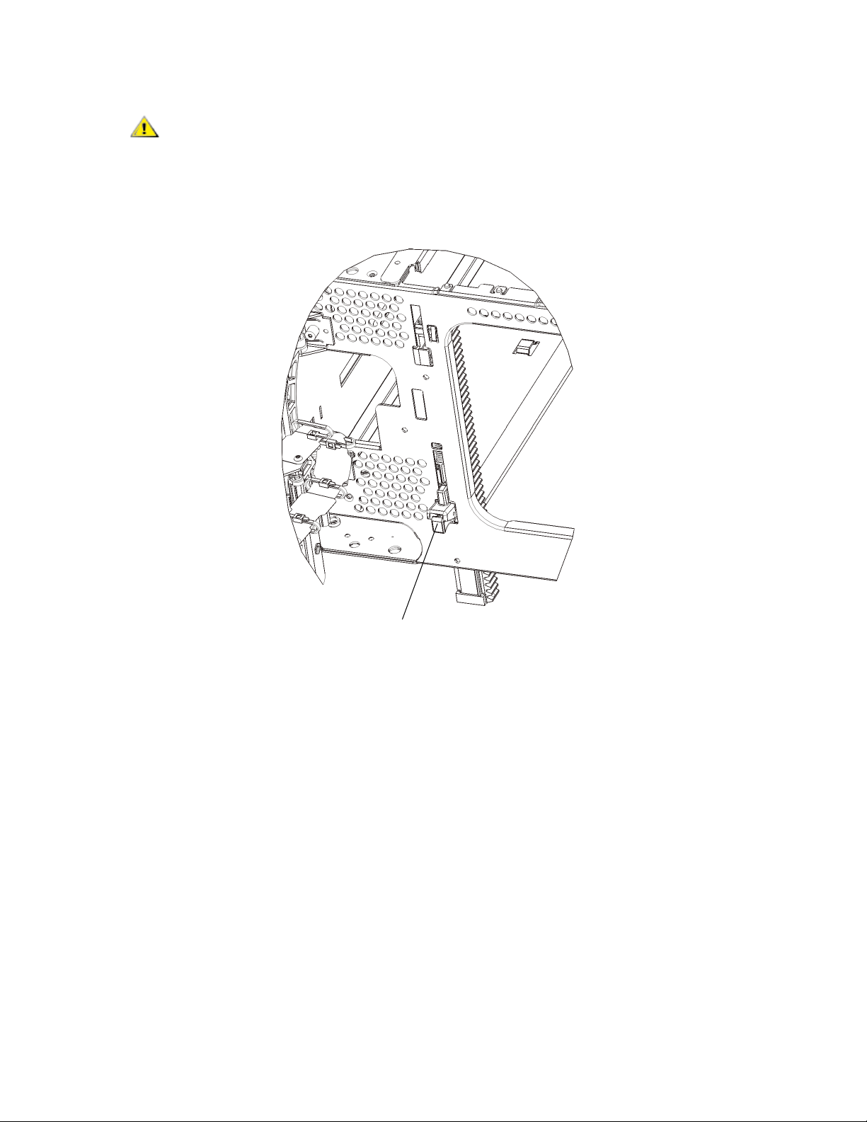
1 Park the robot assembly in the control module.
a. Open the I/E station and access doors of each module.
b. Using your hands, gently lift the robot assembly into the control module. The robot assembly
should glide slowly and with some resistance.
CAUTION
plate. Lifting the robot by the thin metal rod will bend the rod.
c. After raising the robot assembly to the approximate middle of the control module, hold it in place
with one hand and, using your other hand, swivel the parking tab toward you. The metal parking
tab is located at the bottom of column 1.
d. Gently release the robot assembly to rest on the parking tab.
Parking tab in “parked”
position
Support the robot assembly by holding onto the broad metal X-axis
2 Remove top or bottom cover plates if necessary.
There should only be one top cover and one bottom cover plate in the final configuration. There should
be no cover plates in between modules.
8 Scalar i500 Getting Started Guide
Page 9

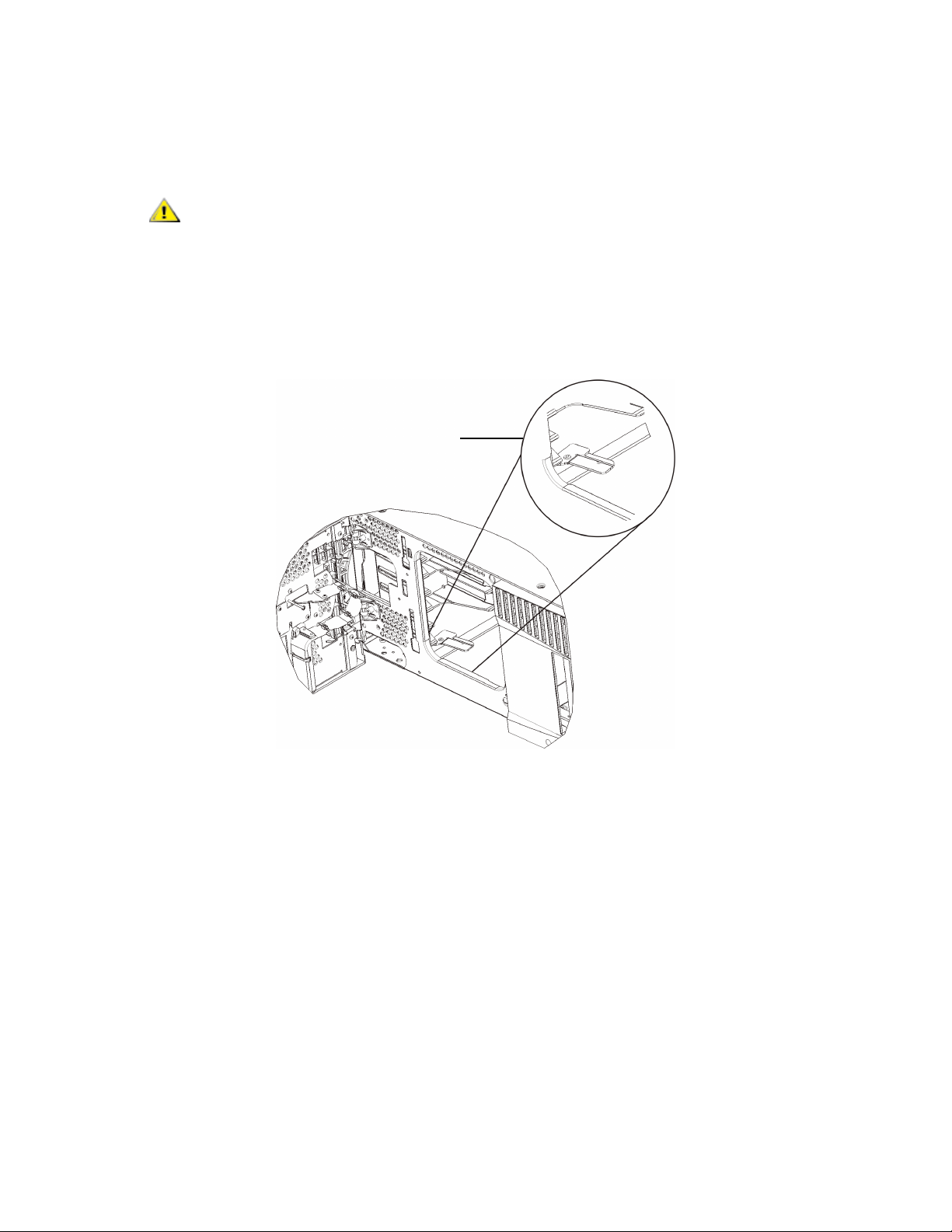
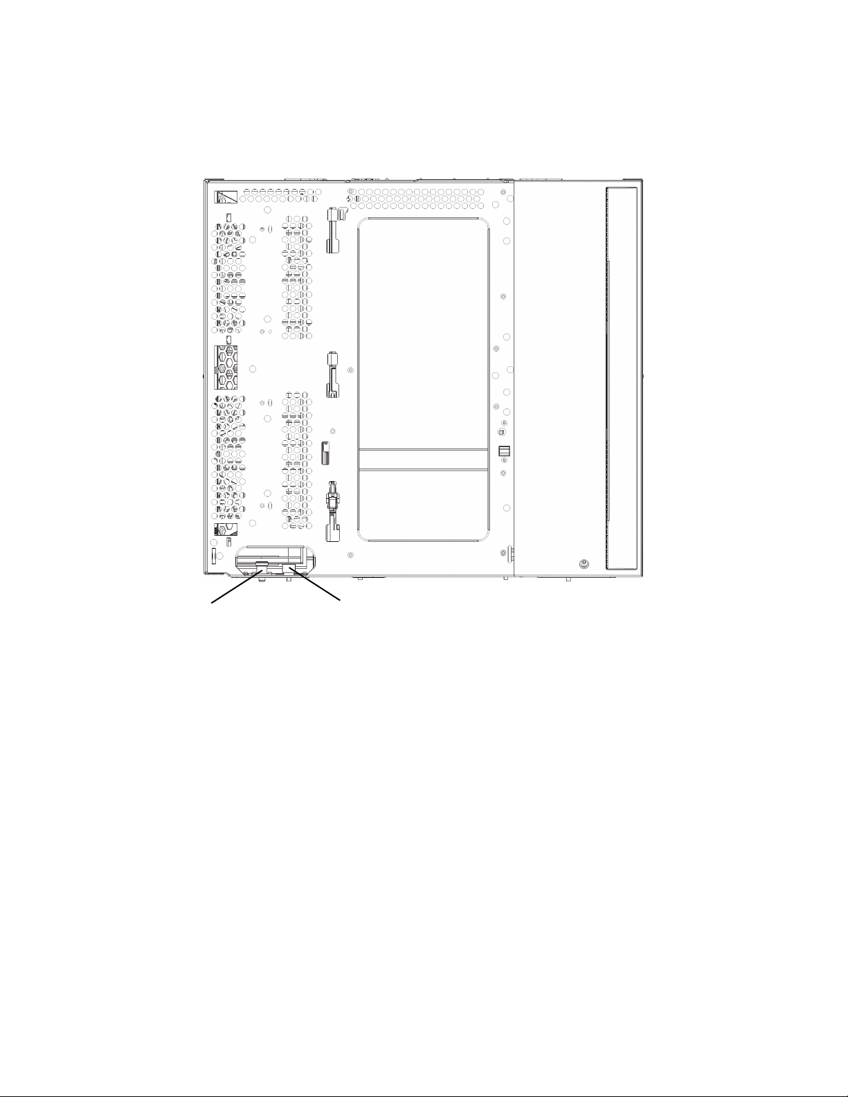
3 Install the expansion module(s).
a. Open the 9U expansion module’s access door and raise the guide pin by pulling it up and
turning it slightly as if it were a screw. Otherwise, the guide pin may scratch the front doors of
the module on which you are stacking.
Guide pin Thumbscrew
b. Lift the new expansion module and, from the front of the library, place it in the desired location.
c. If stacking the expansion module on top of another module, lower the module’s guide pin
(located at the base of the front of the module) by turning it and pushing it down. Then secure
the two modules together by tightening the two thumbscrews at the base of the front of the
module and the two thumbscrews located at the base of the back of the module.
d. Tighten all thumbscrews located at the base of the front and back of the modules.
e. Fasten the module to the rack with rack ears. For instructions, see “Installing the Rackmount
Kit” in the Scalar i500 User’s Guide.
Scalar i500 Getting Started Guide 9
Page 10
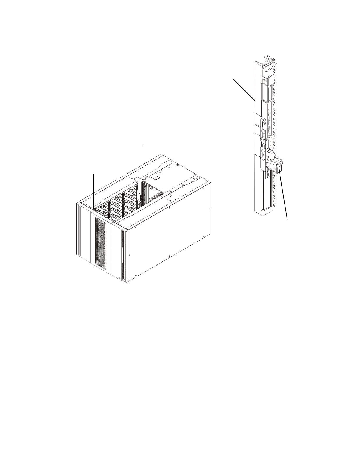
f. If stacking the expansion module on top of another module, engage the Y-rails of the new
module in your library configuration. Ensure that the Y-rails are properly aligned and the
thumbscrews are tightened.
Y-rail (this end up)
Rear Y-rail
Front Y-rail
Squeeze here
to release
g. From the front of the library, open the I/E station and access doors of the expansion module.
Squeeze the handle of the Y-rail release mechanism, lift it out of its locked position, and slide
it downward as far as it will go.
h. From the back of the library, find the rear Y-rail release mechanism, which is located in the
interior of the right side of the module. Squeeze the handle of the Y-rail release mechanism, lift
it out of its locked position, and slide it downward as far as it will go.
10 Scalar i500 Getting Started Guide
Page 11
CAUTION
Y-rails on both the front and back of the library. If a gap exists, the
library cannot mechanically initialize.
Doing this aligns the Y-rails with the Y-rails of the module beneath it.
Check to make sure that there is no gap between the top and bottom
i. Repeat these steps for each expansion module you are installing.
4 Install the control module.
a. Open the control module’s I/E station door and access door.
b. Lift the control module and place it in the desired location.
c. If stacking the control module on top of another module, secure the two modules together by
tightening the two thumbscrews at the base of the front1 of the module and the two
thumbscrews located at the base of the back of the module. Then lower the module’s guide pin
(located at the base of the front of the module) by turning it and pushing it down.
d. Tighten all thumbscrews located at the base of the front and back of the modules.
e. Use the rack ears to fasten the control module to the rack. For instructions, see “Installing the
Rackmount Kit” in the Scalar i500 User’s Guide.
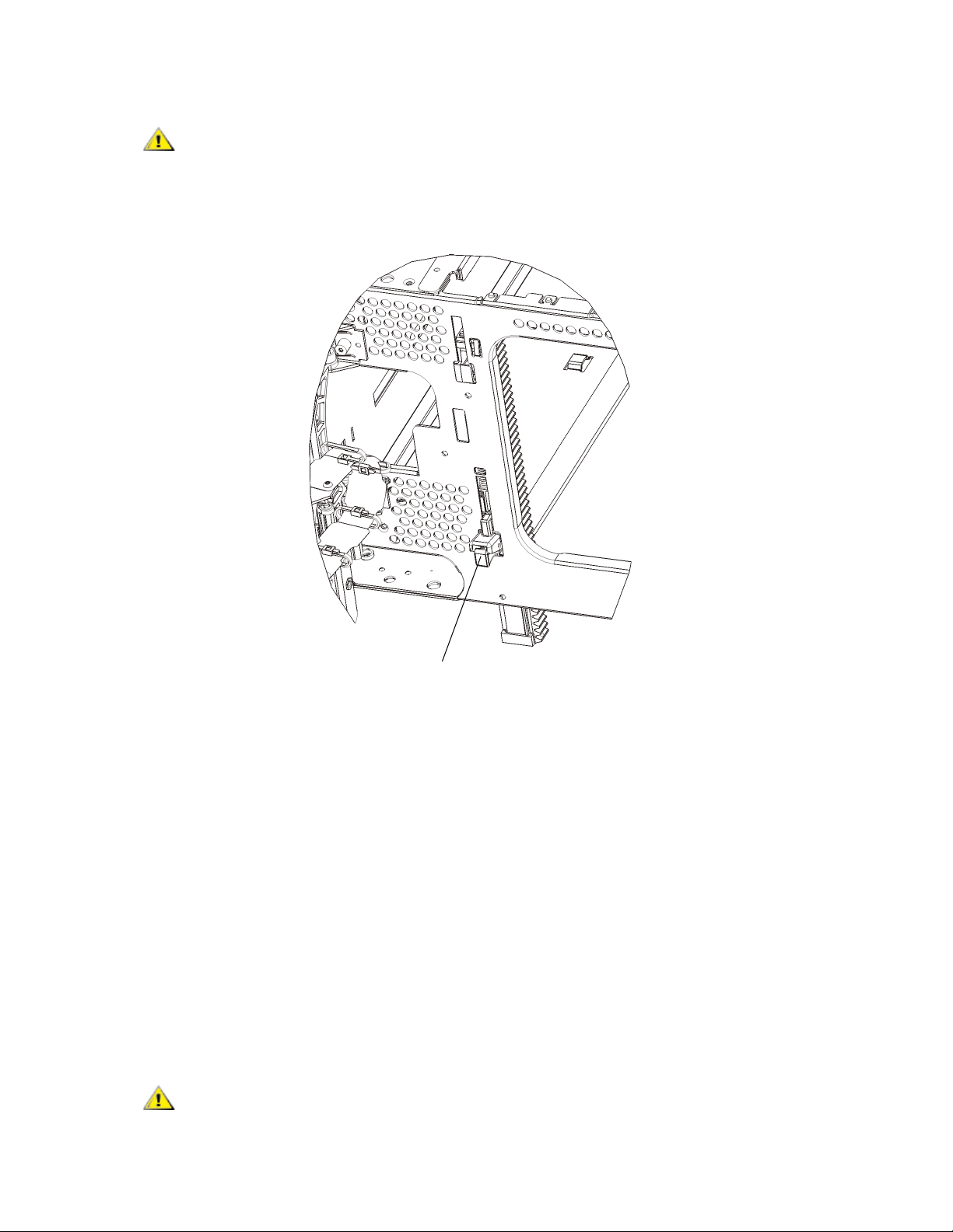
5 Unpark the robot assembly.
a. Gently raise the robot assembly so that it no longer rests on the parking tab.
Support the robot assembly by holding onto the broad metal X-axis
CAUTION
plate. Lifting the robot by the thin metal rod will bend the rod.
Y-rail in unlocked, functional
position
Scalar i500 Getting Started Guide 11
Page 12
b. With your free hand, swivel the parking tab away from you until it is removed completely from
the interior of the module. When replaced correctly, the parking tab will not accidentally swivel
into the path of the robot.
c. Gently release the robot assembly. It will lower to the bottom module of the library.
Parking tab in “unparked”
position
12 Scalar i500 Getting Started Guide
Page 13

Step 4: Install the Module Components
For instructions on any of the following steps, see “Adding, Removing, and Replacing” in the Scalar i500
User’s Guide.
1 If not already installed, install the library control blade (LCB) in the control module.
2 Install the tape drives.
3 Install the power supplies.
4 Install the Fibre Channel (FC) I/O blade (if required and not already installed).
5 Close the library’s I/E station door and access door.
Step 5: Connect the Tape Drive Cables
Follow the instructions below for the type(s) of tape drives installed in your library. The instruction sets are:
• Connecting Parallel SCSI Cables
• Connecting Fibre Channel Cables Directly to Host or Switch
• Connecting Fibre Channel Cables Through an I/O Blade
• Connecting Serial Attached SCSI (SAS) Cables
A library can have any combination of SCSI, FC, and SAS drives, connected directly to hosts or through I/
O blades. You may need to follow more than one set of instructions below. For more detailed instructions,
see the Scalar i500 User’s Guide.
Scalar i500 Getting Started Guide 13
Page 14
Connecting Parallel SCSI Cables
There are two recommended ways to cable SCSI tape drives: two tape drives per SCSI bus or one tape
drive per SCSI bus.
To connect two tape drives per SCSI bus:
1 Connect one end of the SCSI cable to the top SCSI port of the bottom tape drive. Then connect the
other end of the cable to the bottom SCSI port of the tape drive above. To avoid possible performance
issues, do not connect more than two tape drives per SCSI bus.
2 Use another SCSI cable to connect the bottom tape drive of the SCSI bus to your host system.
3 Use a SCSI terminator to terminate the top tape drive of the SCSI bus.
To connect one tape drive per SCSI bus:
4 Use a SCSI cable to connect the bottom port of the tape drive to your host system.
5 Attach a SCSI terminator to terminate the top port of the tape drive.
CAUTION
The library supports a maximum cable length of 12 meters (including
internal wiring) for Ultra 160 SCSI and Ultra 320 SCSI cables.
14 Scalar i500 Getting Started Guide
Page 15
Connecting Fibre Channel Cables Directly to Host or Switch
For each tape drive:
1 Connect one end of a Fibre Channel cable to the Fibre Channel port on the tape drive.
2 Connect the other end of the cable to your host or switch.
Scalar i500 Getting Started Guide 15
Page 16
Connecting Fibre Channel Cables Through an I/O Blade
For each tape drive:
1 Connect one end of a Fibre Channel cable to the Fibre Channel port on the tape drive.
2 Connect the other end of the cable to an initiator port (lower ports 3 – 6) on the nearest Fibre Channel
I/O blade.
For each Fibre Channel I/O blade:
3 Connect one end of a Fibre Channel cable to one of the target ports (upper ports 1 and 2) on the Fibre
Channel I/O blade.
4 Connect the other end of the cable to your host or switch.
16 Scalar i500 Getting Started Guide
Page 17
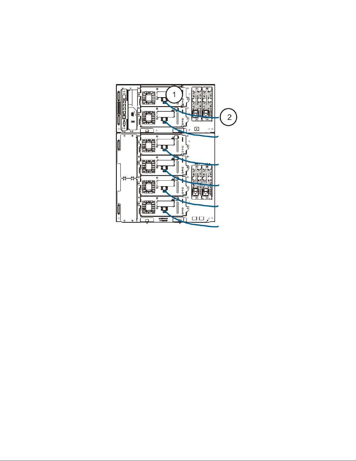
Connecting Serial Attached SCSI (SAS) Cables
For each tape drive:
1 Connect one end of a SAS cable to the SAS port on the tape drive.
2 Connect the other end of the cable directly to the host.
CAUTION
The library supports SAS host cable lengths meeting the standard
SAS specification.
Scalar i500 Getting Started Guide 17
Page 18

Step 6: Connect the Library Cables
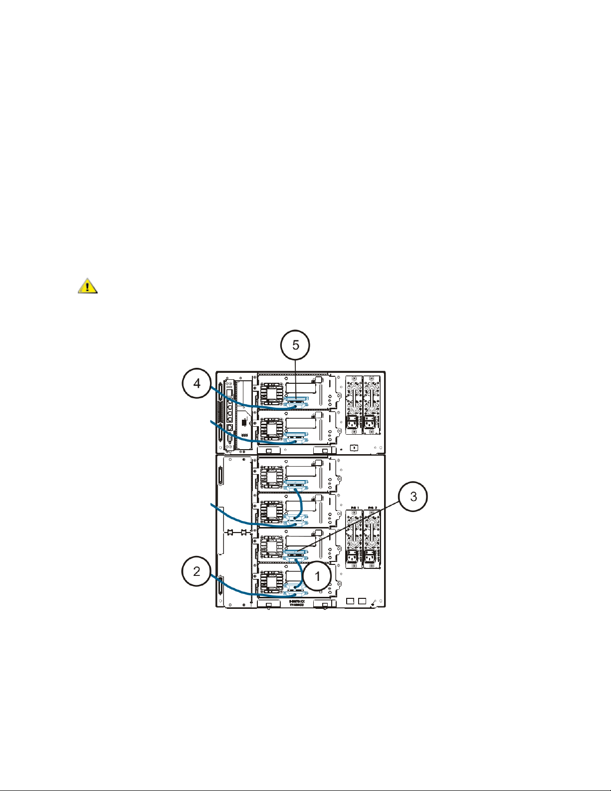
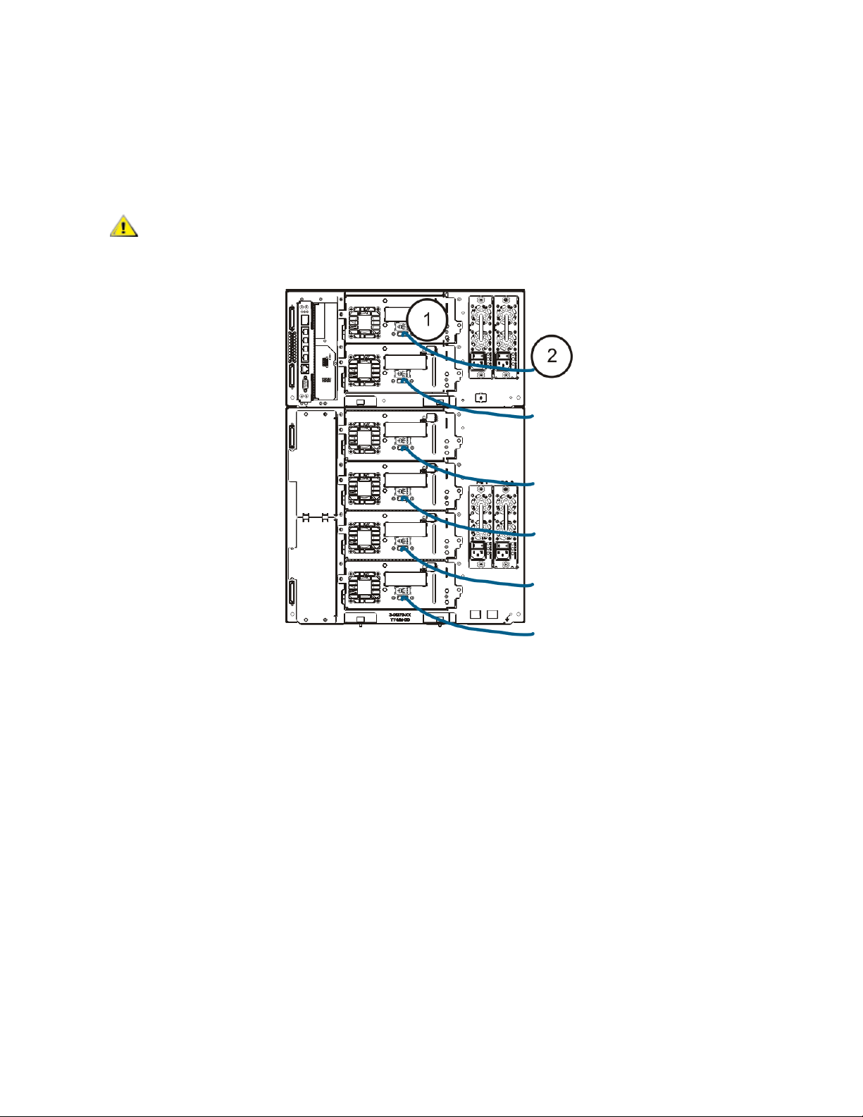
1 Connect module cables and module terminators.
All libraries must use module terminators. Libraries that consist of multiple modules must use moduleto-module cables.
CAUTION
a. Using the module-to-module cables from the accessory kit, connect each module to the one
above it. Connect one end of the cable to the bottom module. Then connect the other end of
the cable to the module above it.
b. Using the module terminators from the accessory kit, terminate the topmost and bottommost
modules.
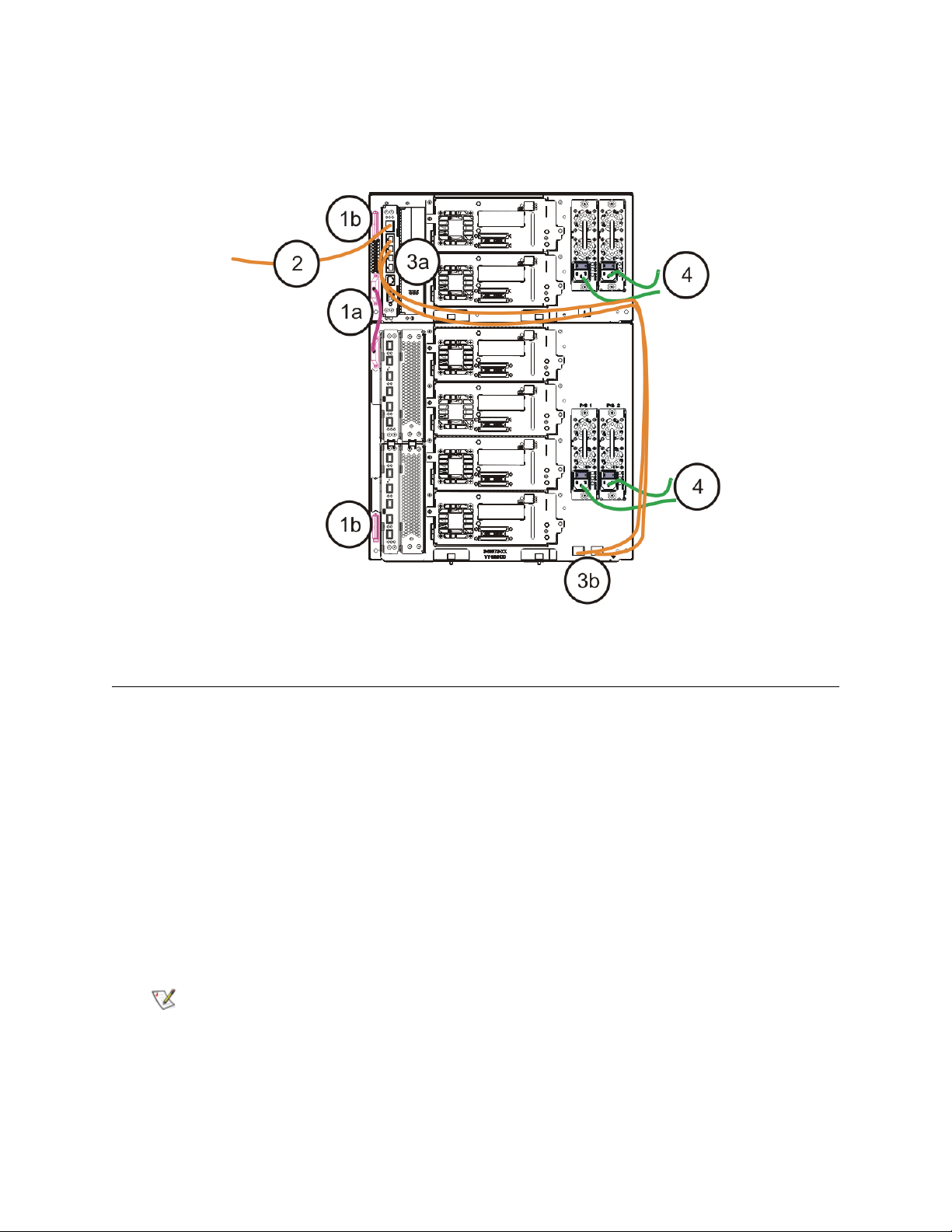
2 Connect the Ethernet cable.
Connect an Ethernet cable to the top Gigabit Ethernet port on the library control blade (LCB) for remote
access to the library via the web client. (Ethernet cable not supplied.)
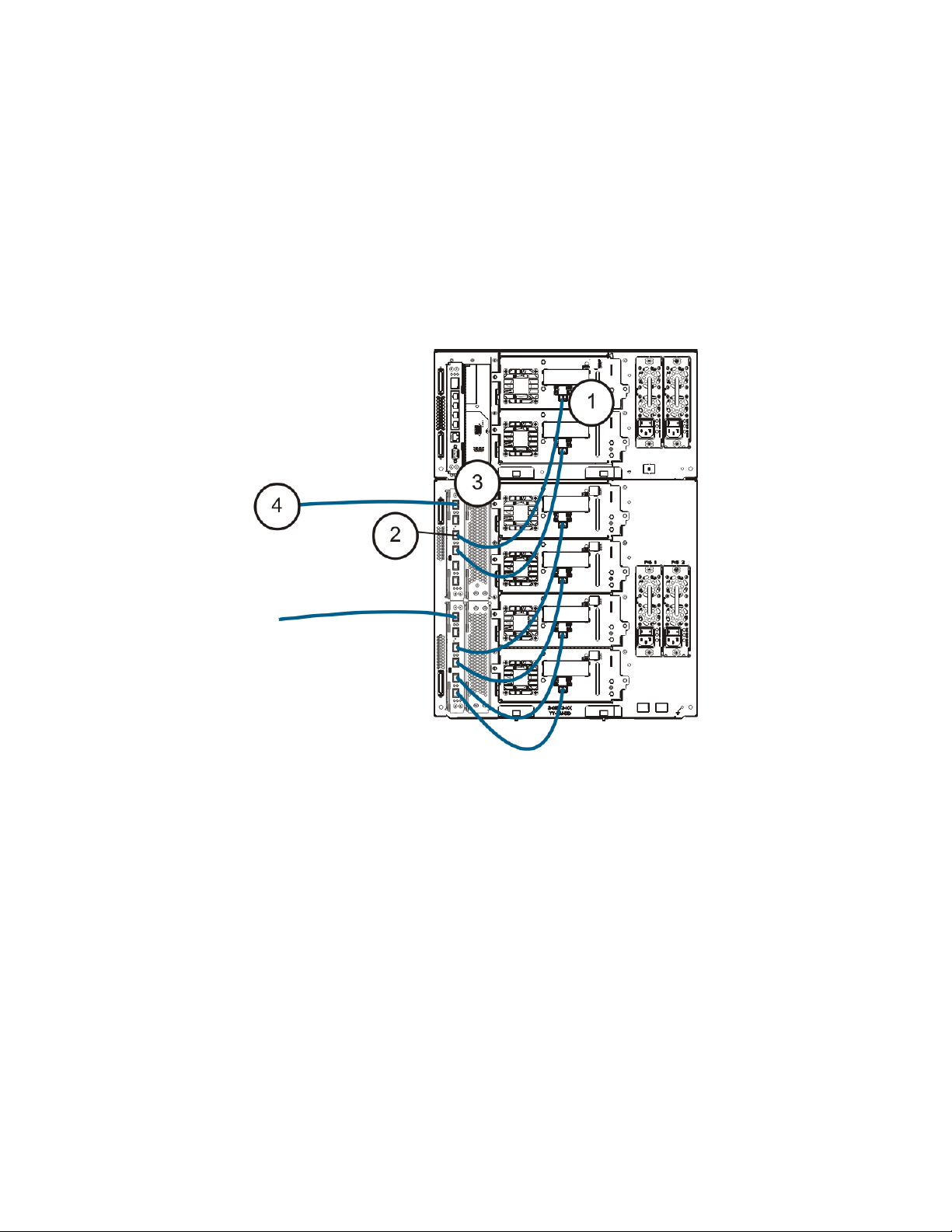
3 Connect the module Ethernet cables (if required).
Perform this step if your library contains at least one Fibre Channel I/O blade.
Use Ethernet cables to connect the LCB in the library control module to each expansion module that
contains a Fibre Channel I/O blade. For each Fibre Channel I/O blade installed in an expansion module:
a. Connect one end of the Ethernet cable to any of the four middle Ethernet ports on the LCB
Ethernet hub. (The uppermost port is for remote access to the library via the web client, and the
bottommost port is for service access.)
b. Connect the other end of the cable to the appropriate port on the 9U Expansion Module. If the
Fibre Channel I/O blade is installed in the upper bay, use the port labelled "UPPER." If the Fibre
Channel I/O blade is installed in the lower bay, use the port labelled "LOWER."
The module terminator is not the same as a SCSI terminator. Using a SCSI
terminator instead of a module terminator can damage the library.
18 Scalar i500 Getting Started Guide
Page 19
4 Connect the power cords.
At least one power supply is required for each module that contains tape drives.
For each power supply, connect one end of the power cord to the power supply. Then connect the other
end to a nearby grounded AC power source (of the type marked on the product label).
Step 7: Using the Library For the First Time
1 Power on the library.
a. Turn on the rear power switch of each of the power supplies.
b. Press the power switch on the front of the library once.
c. Power up the host system.
2 Verify communication with all devices on the bus.
3 Configure the library.
When you first power on the library, the operator panel displays the Setup Wizard. You must start using
the Setup Wizard on the operator panel. After performing initial configuration, you can continue to use
the Startup Wizard on the operator panel or use the web client. It is recommended that you use the web
client after basic initial configuration because there are many more options available to you on the web
client.
Note
You may skip initial configuration, or exit partway through and come back.
If you do this, the settings you do not configure will be assigned default
settings until you change them. Default settings:
- DCHP enabled
- 6 I/E station slots
- 0 Cleaning cartridge slots
- The number of partitions equals the number of tape drive interface types
the library contains (SCSI, FC, or SAS).
Scalar i500 Getting Started Guide 19
Page 20

The recommended procedure for using the Setup Wizard for the initial configuration is as follows:
a. Turn on the library and begin using the Setup Wizard on the operator panel.
b. The Setup Wizard prompts you to enter the network settings that allow the web client to access
the library. Be sure to complete this step.
c. When the Setup Wizard screen text prompts you to choose Local or Remote, choose
Remote.
d. Log out of the operator panel.
e. Using the default administrative account, log in to the web client. Type admin in the User Name
text box and password in the Password text box.
f. Complete the Setup Wizard screens on the web client interface. The final Setup Wizard
screen will prompt you to apply your settings.
When you have completed the Setup Wizard, the Library Configuration report appears on the web
client. The Library Configuration report provides information on the library’s tape drives, partitions, I/E
stations, storage slots, cleaning slots, and loaded media.
You can configure network settings, set date and time, create user accounts, configure Import/Export
(I/E) slots, and perform other tasks that allow you to begin using the library. If you need to license
additional storage slots, contact technical support for license keys to activate the additional slots. For
contact information, see “About This Guide and Your Product” in the Scalar i500 User’s Guide.
For instructions on configuring the library, see “Configuring Your Library” in the Scalar i500 User’s
Guide. See also the library’s online Help. To access the online Help system, click the Help icon at the
top right of the web client or operator panel user interface.
4 Load tape cartridges into the library.
For instructions on importing and bulkloading tape cartridges, see ”Running the Library” in the Scalar
i500 User’s Guide.
5 Assign tape drives to partitions (if using the I/E commands).
When manual cartridge assignment is enabled (the default setting), you cannot import cartridges using
the I/E commands until you have assigned them to a partition. The Assign IE screen on the operator
panel will prompt you to assign them to a partition.
If manual cartridge assignment is disabled, the Assign IE screen does not appear and the cartidges in
the I/E station are visible to all partitions, as well as the system partition, and can be used by any
partition. For more information, see the Scalar i500 User’s Guide.
6 Connect to the host application.
Set up the connection to the library host application. If your host application inventories the location of
each tape cartridge in the library, open the host application and perform a reinventory to sync the logical
inventory with the physical inventory of the library.
For instructions, see your host application documentation.
7 Register the library.
For more information about registering the library, see “Configuring the Library” in the Scalar i500 User’s
Guide.
20 Scalar i500 Getting Started Guide
Page 21

Step 8: Run the Library
You are now ready to start using your library. For information about using your library, see “Running the
Library” in the Scalar i500 User’s Guide. See also the library’s online Help. To access the online Help
system, click the Help icon at the top right of the web client or operator panel user interface.
Note
Note
You can download the latest drivers from: www.quantum.com.
The maximum number of expansion modules supported in a library depends on
the level of firmware the library is running. The latest firmware must be installed
on the library if you are upgrading from a 5U, 14U, 23U configuration to a larger
configuration. The latest firmware can be found at www.quantum.com
.
Scalar i500 Getting Started Guide 21
Page 22

22 Scalar i500 Getting Started Guide
Page 23

Scalar i500 - Einführungshandbuch
Das Scalar i500 - Einführungshandbuch bietet eine Übersicht über die erforderlichen Schritte, um die Scalar
i500 Bibliothek auszupacken, einzustellen und zu installieren. Weitere Informationen über die Konfiguration
und das Ausführen Ihrer Bibliothek sowie das Hinzufügen, Entfernen und Ersetzen von Teilen finden Sie im
Scalar i500 Benutzerhandbuch.
Anmerkungen zu Versionen sind auch für dieses Produkt verfügbar. Die Anmerkungen zu Versionen
beschreiben Änderungen zu Ihrem System oder Firmware seit der letzten Version, geben
Kompatibilitätsauskunft und erörtern alle bekannten Probleme und Behelfslösungen.Die Anmerkungen zu
Versionen können unter www.quantum.com
Dokumentation im Scalar i500 Benutzerhandbuch unter "Zu diesem Handbuch und Ihrem Produkt" finden.
gefunden werden. Sie können eine Liste der zusätzlichen
Anmerkung
WARNUNG
WARNUNG
WARNUNG
Lesen Sie vor der Inbetriebnahme dieses Produkts alle Anleitungen und Warnungen in
diesem Dokument und im System-, Sicherheits- und Betriebsbestimmungen-
Handbuch. Seien Sie außerdem sicher, dieses Dokument in Verbindung mit dem
Scalar i500-Benutzerhandbuch zu verwenden.
OHNE BANDLAUFWERKE, BANDKASSETTEN ODER NETZTEILE
WIEGT EIN 5U-STEUERMODUL ETWA 26 KG. EIN 9UERWEITERUNGSMODUL WIEGT OHNE BANDLAUFWERKE,
BANDKASSETTEN ODER NETZTEILE MEHR ALS 29 KG. UM
ERNSTHAFTE VERLETZUNG ZU VERMEIDEN, SIND ZWEI PERSONEN
ERFORDERLICH, UM DIE MODULE SICHER IN DIE POSITION ZU
HEBEN.
DIE STECKDOSE MUSS IN DER NÄHE DER BIBLIOTHEK
VERFÜGBAR UND LEICHT ZUGÄNGLICH SEIN.
ALLE BIBLIOTHEKEN, DIE HÖHER ALS 14U SIND, MÜSSEN IN EINEM
RACK INSTALLIERT WERDEN, DAS ÜBER EIN HAUPTSICHERUNGSTERMINAL (ERDUNG) VERFÜGT. ZUDEM MUSS DIE STROMVERSORGUNG ÜBER EINE INDUSTRIELLE STECKDOSE UND EINE
STECKDOSE UND/ODER EINE STECKVORRICHTUNG ERFOLGEN,
DIE IEC 60309 (ODER EINEM ENTSPRECHENDEN LANDESSTANDARD) ENTSPRICHT, UND ÜBER EINEN SCHUTZERDLEITER
(ERDUNG) MIT EINEM QUERSCHNITT VON MINDESTENS 1,5 MM
(14 AWG) VERFÜGEN.
2
LASSEN SIE AN DER VORDER- UND HINTERSEITE DER BIBLIOTHEK
EINEN RAUM VON JEWEILS 60 CM (24 ZOLL) FREI, DAMIT DIE LUFT
GUT ZIRKULIEREN KANN UND EIN PROBLEMLOSER ZUGRIFF AUF
DIE BIBLIOTHEK GEWÄHRLEISTET IST.
WARNUNG
Scalar i500 - Einführungshandbuch 23
KEINESFALLS SOLLTE EIN RACK BEWEGT WERDEN, WÄHREND ES
MIT EINEM ODER MEHREREN MODULEN GELADEN IST.
Page 24

Schritt 1: Auspacken der Bibliothek
1 Packen Sie die Bibliothek aus.
Entfernen Sie entsprechend der Auspackanleitung, die mit der Bibliothek geliefert wurde, die
Außenverpackung der Bibliothek, aber lassen Sie die Bibliothek im untersten Verpackungseinsatz.
VORSICHT
2
Überprüfen Sie den Inhalt der Verpackung, damit dieser nicht in der Verpackung verrutschen kann.
3 Entfernen Sie die Innenverpackung.
VORSICHT
WARNUNG
4 Entfernen Sie die Bandlaufwerke aus der Bibliothek.
Informationen über die Entfernung von Bandlaufwerken, finden Sie im Scalar i500 Benutzerhandbuch
unter "Hinzufügen, Entfernen und Ersetzen".
Bewahren Sie alle Verpackungsmaterialien auf, falls Sie die Bibliothek
in der Zukunft entfernen oder versenden müssen.
Stellen Sie sicher, dass Sie die folgenden Artikel entfernen:
• Der Riemen, der die Robotik an seinem Platz hält. Lösen Sie den
Klettverschluss und haken Sie jedes Ende des Riemens aus.
• Der ganze Karton und Schaumstoff, die die Robotik umgeben.
OHNE BANDLAUFWERKE, BANDKASSETTEN ODER NETZTEILE WIEGT
EIN 5U-STEUERMODUL ETWA 26 KG. EIN 9U-ERWEITERUNGSMODUL
WIEGT OHNE BANDLAUFWERKE, BANDKASSETTEN ODER NETZTEILE
MEHR ALS 29 KG. UM ERNSTHAFTE VERLETZUNG ZU VERMEIDEN,
SIND ZWEI PERSONEN ERFORDERLICH, UM DIE MODULE SICHER IN
DIE POSITION ZU HEBEN.
5 Entfernen Sie die Netzteile aus der Bibliothek.
Informationen über das Entfernen von Netzteilen finden Sie im Scalar i500 Benutzerhandbuch unter
"Hinzufügen, Entfernen und Ersetzen".
6 Wählen Sie einen optimalen Speicherort für die Bibliothek.
Um Schäden zu vermeiden, muss die Bibliothek an einem stabilen Speicherort aufgestellt werden.
Weitere Informationen zum Finden eines optimalen Speicherortes für Ihre Bibliothek finden Sie im
System-, Sicherheits-, und Betriebsbestimmungen-Handbuch .
WARNUNG
• Stellen Sie sicher, dass eine Stromquelle (nur des auf dem Produktetikett gekennzeichneten Typs)
verfügbar ist. Stromvoraussetzungen finden Sie im Kapitel "Technische Daten" im Scalar i500
Benutzerhandbuch.
• Kennzeichnen Sie alle Kabel, um das Betreten oder Einklemmen mit Gegenständen, die auf oder
gegen sie gelegt sind, zu vermeiden. Achten Sie besonders auf das Kabel an der Wandsteckdose
und die Stelle, an der das Kabel aus der Bibliothek austritt. Empfohlene Verkabelungsverfahren
finden Sie im Scalar i500 Benutzerhandbuch.
• Stellen Sie sicher, dass keine Gegenstände herunterfallen und keine Flüssigkeiten ins Gehäuse
der Bibliothek durch Öffnungen gegossen werden.
DIE STECKDOSE MUSS IN DER NÄHE DER BIBLIOTHEK VERFÜGBAR
UND LEICHT ZUGÄNGLICH SEIN
.
24 Scalar i500 - Einführungshandbuch
Page 25
Schritt 2: Installation des Rackmount-Montagesatzes (optional für 5U und 14U)
Alle Scalar i500-Bibliotheken, die höher als 14U sind, müssen in einem Rack installiert werden. Das Rack
sichert das unterste Modul, und alle anderen Module werden dann am untersten Modul gesichert. Die
Installation der Module ins Rack erfordert mindestens zwei Personen. Anweisungen finden Sie im Scalar
i500 Benutzerhandbuch unter "Installation des Rackmount-Montagesatzes".
Schritt 3: Installation des/der Moduls/Module
Es gibt zwei mögliche Bibliothekskonfigurationen:
• Installation des Steuermoduls als eine eigenständige Einheit
• Installation einer Multimodul-Bibliothekskonfiguration
Installation des Steuermoduls als eine eigenständige Einheit
1 Öffnen Sie die I/E-Station- und Zugriffstür der Bibliothek.
2 Heben Sie das Steuermodul und legen Sie es in den gewünschten Speicherort.
3 Wenn Sie das Steuermodul in ein Rack legen, verwenden Sie die Rack-Laschen, um das Steuermodul
am Rack zu befestigen. Anweisungen finden Sie im Scalar i500-Benutzerhandbuch unter "Installation
des Rackmount-Montagesatzes".
4 Fahren Sie die Installation mit Schritt 4: Installation der Modulkomponenten
auf der Seite 31 fort.
Installation einer Multimodul-Bibliothekskonfiguration
Folgen Sie diesen Anweisungen, wenn Sie eine neue Multimodul-Bibliothek installieren, oder wenn Sie
Erweiterungsmodule zu einer vorhandenen Bibliothek hinzufügen.
Erforderliche Hilfsprogramme:
• Kreuzschlitzschaubenzieher #2, um die obere Abdeckplatte zu entfernen und zu ersetzen.
• T10 TORX-Schraubenzieher, um die untere Abdeckplatte zu entfernen und zu ersetzen.
Es gibt keine Beschränkungen, wo das Steuermodul in der Bibliothekskonfiguration installiert werden kann.
Jedoch wird empfohlen, das Steuermodul für Bibliothekskonfigurationen bis zu 32U über allen installierten
9U-Erweiterungsmodulen zu platzieren. Es wird empfohlen, das Steuermodul für 41UBibiliothekskonfigurationen über den drei 9U-Erweiterungsmodulen und unter dem obersten
Erweiterungsmodul zu platzieren.
Abdeckplatte
Abdeckplatte Erweiterungsmodul
Abdeckplatte STEUERMODUL STEUERMODUL
Abdeckplatte STEUERMODUL Erweiterungsmodul Erweiterungsmodul
Abdeckplatte STEUERMODUL Erweiterungsmodul Erweiterungsmodul Erweiterungsmodul
STEUERMODUL Erweiterungsmodul Erweiterungsmodul Erweiterungsmodul Erweiterungsmodule
Abdeckplatte Abdeckplatte Abdeckplatte Abdeckplatte Abdeckplatte
5U 14U 23U 32U 41U
Scalar i500 - Einführungshandbuch 25
Page 26
1 Stellen Sie die Robotikeinheit im Steuermodul ab.
a. Öffnen Sie die I/E-Station und Zugriffstüren jedes Moduls.
b. Heben Sie die Robotikeinheit behutsam mit Ihren Händen in das Steuermodul. Die
Robotikeinheit sollte langsam und mit etwas Widerstand gleiten.
VORSICHT
X-Achse festhalten. Wenn die Robotik durch die dünne Metallstange
gehoben wird, wird die Stange gebogen.
c. Nachdem die Robotikeinheit bis ungefähr zur Mitte des Steuermoduls angehoben wurde,
halten Sie sie mit einer Hand an dieser Stelle fest und drehen Sie mit der anderen Hand das
Feststellregister auf sich zu. Das metallene Feststellregister befindet sich am unteren Ende der
Säule 1.
d. Lösen Sie behutsam die Robotikeinheit, damit sie auf dem Feststellregister liegen kann.
Feststellregister in
"geparkter" Position
Stützen Sie die Robotikeinheit, indem Sie die breite, metallene Platte der
2 Entfernen Sie nötigenfalls die obere oder untere Abdeckplatte.
Es sollte nur eine obere und eine untere Abdeckplatte bei der Endkonfiguration vorhanden sein.
Zwischen den Modulen sollten keine Abdeckplatten vorhanden sein.
26 Scalar i500 - Einführungshandbuch
Page 27
3 Installieren Sie das(die) Erweiterungsmodul(e).
a. Öffnen Sie die Zugriffstür des 9U-Erweiterungsmoduls und heben Sie den Führungsstift an,
indem Sie ihn herausziehen und wie eine Schraube etwas drehen. Andernfalls kann der
Führungsstift die Vordertüren des Moduls verkratzen, auf dem Sie stapeln.
Führungsstift Rändelschraube
b. Heben Sie das neue Erweiterungsmodul an und legen Sie es auf der Vorderseite der Bibliothek
in den gewünschten Speicherort.
c. Wenn das Erweiterungsmodul über ein anderes Modul gestapelt wird, senken Sie den
Führungsstift des Moduls (befindet sich am Boden der Vorderseite des Moduls), indem Sie ihn
drehen und nach unten drücken. Dann befestigen Sie die zwei Module, indem Sie die zwei
Rändelschrauben am Boden der Vorderseite des Moduls und die zwei Rändelschrauben am
Boden der Hinterseite des Moduls festziehen.
d. Ziehen Sie alle Rändelschrauben am Boden der Vorder- und Rückseite der Module fest.
e. Befestigen Sie das Modul am Rack mit Rack-Laschen. Anweisungen finden Sie im Scalar i500-
Benutzerhandbuch unter "Installation des Rackmount-Montagesatzes".
Scalar i500 - Einführungshandbuch 27
Page 28

f. Wenn das Erweiterungsmodul über ein anderes Modul gestapelt wird, klinken Sie Y-Schienen
des neuen Moduls in Ihrer Bibliothekskonfiguration ein. Stellen Sie sicher, dass die Y-Schienen
richtig ausgerichtet und die Rändelschrauben festgezogen sind.
Y-Schiene (dieses Ende
nach oben)
Hintere Y-Schiene
Vordere Y-
Schiene
Zum Lösen
hier drücken
g. Öffnen Sie die I/E-Station und Zugriffstüren des Erweiterungsmoduls auf der Vorderseite der
Bibliothek. Drücken Sie den Griff des Entriegelungsmechanismus der Y-Schiene, heben Sie ihn
aus seiner verriegelten Position und lassen Sie ihn soweit wie möglich nach unten gleiten.
h. Auf der Rückseite der Bibliothek finden Sie den Entriegelungsmechanismus der Y-Schiene, der
sich im Inneren der rechten Modulseite befindet. Drücken Sie den Griff des
Entriegelungsmechanismus der Y-Schiene, heben Sie ihn aus seiner verriegelten Position und
lassen Sie ihn soweit wie möglich nach unten gleiten.
28 Scalar i500 - Einführungshandbuch
Page 29
VORSICHT
den oberen und unteren Y-Schienen sowohl auf der Vorder- als auch
auf der Rückseite der Bibliothek gibt. Wenn eine Lücke besteht, kann
die Bibliothek nicht mechanisch initialisieren.
Dadurch werden die Y-Schienen nach den Y-Schienen des unteren Moduls ausgerichtet.
Überprüfen Sie, um sicherzustellen, dass es keine Lücke zwischen
Y-Schiene in entriegelter,
funktionsfähiger Position
i. Wiederholen Sie diese Schritte für jedes Erweiterungsmodul, das Sie installieren.
4 Installieren Sie das Steuermodul.
a. Öffnen Sie die I/E-Station- und Zugriffstür des Steuermoduls.
b. Heben Sie das Steuermodul und legen Sie es in den gewünschten Speicherort.
c. Wenn das Steuermodul über ein anderes Modul gestapelt wird, befestigen Sie die zwei Module,
indem Sie die zwei Rändelschrauben am Boden der Vorderseite 1 und die zwei
Rändelschrauben am Boden der Rückseite des Moduls festziehen. Dann senken Sie den
Führungsstift des Moduls (befindet sich am Boden der Vorderseite des Moduls), indem Sie ihn
drehen und herunterdrücken.
d. Ziehen Sie alle Rändelschrauben am Boden der Vorder- und Rückseite der Module fest.
e. Verwenden Sie die Rack-Laschen, um das Steuermodul am Rack zu befestigen. Anweisungen
finden Sie im Scalar i500-Benutzerhandbuch unter "Installation des Rackmount-Montagesatzes".
5 Nehmen Sie die Robotikeinheit auf.
Scalar i500 - Einführungshandbuch 29
Page 30

a.
Heben Sie die Robotikeinheit behutsam an, so dass sie nicht mehr auf dem Feststellregister ruht.
VORSICHT
X-Achse festhalten. Wenn die Robotik durch die dünne Metallstange
gehoben wird, wird die Stange gebogen.
b. Drehen Sie das Feststellregister mit der freien Hand von sich weg, bis es völlig aus dem
Inneren des Moduls entfernt ist. Wenn das Feststellregister richtig ersetzt wurde, wird es sich
absichtlich in die Laufbahn der Robotik drehen.
c. Lösen Sie die Robotikeinheit behutsam. Sie wird zum untersten Modul der Bibliothek sinken.
Feststellregister in "ungeparkter" Position
Stützen Sie die Robotikeinheit, indem Sie die breite, metallene Platte der
30 Scalar i500 - Einführungshandbuch
Page 31

Schritt 4: Installation der Modulkomponenten
Anweisungen zu jedem folgenden Schritt finden Sie im Scalar i500 Benutzerhandbuch unter "Hinzufügen,
Entfernen und Ersetzen".
1 Wenn nicht bereits installiert, installieren Sie das LCB (Library Control Blade) im Steuermodul.
2 Installieren Sie die Bandlaufwerke.
3 Installieren Sie die Netzteile.
4 Installieren Sie die Fibre Channel (FC) E/A-Platine (falls erforderlich und nicht bereits installiert).
5 Schließen Sie die I/E-Stations- und Zugriffstür der Bibliothek.
Schritt 5: Anschluss der Bandlaufwerkskabel
Folgen Sie den untenstehenden Anweisungen für den(die) in Ihrer Bibliothek installierten
Bandlaufwerkstyp(en). Die Anleitungszusammenstellung ist:
• Parallele SCSI-Kabel anschließen
• Fibre Channel-Kabel direkt mit dem Host oder Switch verbinden
• Fibre Channel-Kabel durch eine E/A-Platine verbinden
• Seriellen verbundene SCSI (SAS)-Kabel anschließen
Eine Bibliothek kann jede Kombination von SCSI-, FC- und SAS-Laufwerken haben, die direkt mit Hosts
oder durch E/A-Platinen. Sie müssen eventuell mehr als einer untenstehenden Anleitung folgen.
Ausführlichere Anweisungen finden Sie im Scalar i500-Benutzerhandbuch.
Scalar i500 - Einführungshandbuch 31
Page 32

Parallele SCSI-Kabel anschließen
Es gibt zwei empfohlene Methoden, um SCSI-Bandlaufwerke zu verkabeln: zwei Bandlaufwerke pro SCSIBus oder ein Bandlaufwerk pro SCSI-Bus.
Um zwei Bandlaufwerke pro SCSI-Bus zu verbinden:
1 Verbinden Sie ein Ende des SCSI-Kabels mit dem oberen SCSI-Anschluss des unteren Bandlaufwerks.
Dann verbinden Sie das andere Ende des Kabels mit dem unteren SCSI-Anschluss des Bandlaufwerks
oberhalb. Um mögliche Leistungsprobleme zu vermeiden, verbinden Sie nicht mehr als zwei
Bandlaufwerke pro SCSI-Bus.
2 Verwenden Sie ein anderes SCSI-Kabel, um das untere Bandlaufwerk des SCSI-Busses mit Ihrem
Host-System zu verbinden.
3 Verwenden Sie einen SCSI-Terminator, um das obere Bandlaufwerk des SCSI-Busses zu begrenzen.
Um ein Bandlaufwerk pro SCSI-Bus zu verbinden:
4 Verwenden Sie ein SCSI-Kabel, um den unteren Anschluss des Bandlaufwerks mit Ihrem Host-System
zu verbinden.
5 Schließen Sie einen SCSI-Terminator an, um den oberen Anschluss des Bandlaufwerks zu begrenzen.
VORSICHT
Die Bibliothek unterstützt eine maximale Kabellänge von 12 Metern
(einschließlich der internen Verdrahtung) für das Ultra 160 SCSI- und
Ultra 320 SCSI-Kabel.
32 Scalar i500 - Einführungshandbuch
Page 33

Fibre Channel-Kabel direkt mit dem Host oder Switch verbinden
Für jedes Bandlaufwerk:
1 Verbinden Sie ein Ende eines Fibre Channel-Kabels mit dem Fibre Channel-Anschluss am
Bandlaufwerk.
2 Verbinden Sie das andere Ende des Kabels mit Ihrem Host oder Switch.
Scalar i500 - Einführungshandbuch 33
Page 34

Fibre Channel-Kabel durch eine E/A-Platine verbinden
Für jedes Bandlaufwerk:
1 Verbinden Sie ein Ende eines Fibre Channel-Kabels mit dem Fibre Channel-Anschluss am
Bandlaufwerk.
2 Verbinden Sie das andere Ende des Kabels mit einem Initiator-Anschluss (untere Anschlüsse 3 - 6) auf
der nächsten Fibre Channel-E/A-Platine.
Für jede Fibre Channel-E/A-Platine:
3 Verbinden Sie ein Ende eines Fibre Channel-Kabels mit einem der Zielanschlüsse (obere Anschlüsse
1 und 2) auf der Fibre Channel-E/A-Platine.
4 Verbinden Sie das andere Ende des Kabels mit Ihrem Host oder Switch.
34 Scalar i500 - Einführungshandbuch
Page 35

Seriellen verbundene SCSI (SAS)-Kabel anschließen
Für jedes Bandlaufwerk:
1 Verbinden Sie ein Ende eines SAS-Kabels mit dem SAS-Anschluss am Bandlaufwerk.
2 Verbinden Sie das andere Ende des Kabels direkt mit
dem Host.
VORSICHT
Die Bibliothek unterstützt SAS-Host-Kabellängen, übereinstimmend
mit den SAS-Standardangaben.
Scalar i500 - Einführungshandbuch 35
Page 36

Schritt 6: Bibliothekskabel anschließen
1 Schließen Sie Modul-Kabel und Modul-Terminatoren an.
Alle Bibliotheken müssen Modul-Terminatoren verwenden. Bibliotheken, die aus mehreren Modulen
bestehen, müssen Modul-zu-Modul-Kabel verwenden.
VORSICHT
a. Durch die Verwendung der Modul-zu-Modul-Kabel aus dem Zubehörsatz verbinden Sie jedes
Modul mit demjenigen darüber. Verbinden Sie ein Ende des Kabels mit dem unteren Modul.
Dann verbinden Sie das andere Ende des Kabels mit dem Modul darüber.
b. Durch die Verwendung der Modul-Terminatoren aus dem Zubehörsatz begrenzen Sie die
obersten und untersten Module.
2 Schließen Sie das Ethernet-Kabel an.
Verbinden Sie ein Ethernet-Kabel mit dem oberen Gigabit-Ethernet-Anschluss auf dem LCB (Library
Control Blade) für den Remote-Zugriff auf die Bibliothek über den Web-Client. (Ethernet-Kabel nicht
enthalten.)
3 Verbinden Sie die Ethernet-Kabel des Moduls (falls erforderlich).
Führen Sie diesen Schritt aus, wenn Ihre Bibliothek mindestens eine Fibre Channel-E/A-Platine enthält.
Verwenden Sie Ethernet-Kabel, um das LCB im Steuermodul der Bibliothek mit jedem
Erweiterungsmodul zu verbinden, das eine Fibre Channel-E/A-Platine enthält. Für jede in einem
Erweiterungsmodul installierte Fibre Channel-E/A-Platine:
a. Verbinden Sie ein Ende des Ethernet-Kabels mit einem der vier mittleren Ethernet-Anschlüsse
am Ethernet-Hub des LCB. (Der oberste Anschluss ist für den Remote-Zugriff auf die Bibliothek
über den Web-Client, und der unterste Anschluss ist für den Servicezugriff.)
Der Modul-Terminator ist nicht dasselbe wie ein SCSI-Terminator. Wenn
Sie einen SCSI-Terminator anstelle eines Modul-Terminators verwenden,
kann die Bibliothek beschädigt werden.
b. Verbinden Sie das andere Ende des Kabels mit dem entsprechenden Anschluss auf dem 9U-
Erweiterungsmodul. Wenn die Fibre Channel-E/A-Platine im oberen Schacht installiert ist,
verwenden Sie den Anschluss, der die Aufschrift "UPPER” (OBERER) trägt. Wenn die Fibre
Channel-E/A-Platine im unteren Schacht installiert ist, verwenden Sie den Anschluss, der die
Aufschrift "LOWER” (UNTERER) trägt.
36 Scalar i500 - Einführungshandbuch
Page 37

4 Verbinden Sie die Netzkabel.
Mindestens ein Netzteil ist für jedes Modul erforderlich, das Bandlaufwerke enthält.
Verbinden Sie für jedes Netzteil ein Ende des Netzkabels mit dem Netzteil. Dann verbinden Sie das
andere Ende mit einer nahe gelegenen, geerdeten Wechselstrom-Stromquelle (des auf dem
Produktetikett gekennzeichneten Typs).
Schritt 7: Die Bibliothek zum ersten Mal verwenden
1 Schalten Sie die Bibliothek ein.
a. Schalten Sie den hinteren Netzschalter von jedem Netzteil ein.
b. Drücken Sie einmal den Netzschalter auf der Vorderseite der Bibliothek.
c. Schalten Sie das Host-System ein.
2 Überprüfen Sie die Kommunikation mit allen Geräten auf dem Bus.
Scalar i500 - Einführungshandbuch 37
Page 38

3 Konfigurieren Sie die Bibliothek.
Wenn Sie die Bibliothek zum ersten Mal einschalten, zeigt das Bedienfeld den Setup-Assistenten an.
Sie müssen mit der Verwendung des Setup-Assistenten auf dem Bedienfeld beginnen. Nach der
Durchführung der Erstkonfiguration können Sie mit der Verwendung des Start-Assistenten auf dem
Bedienfeld oder des Web-Clients fortfahren. Es wird empfohlen, dass Sie den Web-Client nach der
grundlegenden Erstkonfiguration verwenden, weil noch viele weitere Optionen auf dem Web-Client zur
Verfügung stehen.
Anmerkung
Das empfohlene Verfahren für die Verwendung des Setup-Assistenten für die Erstkonfiguration ist
folgendes:
a. Schalten Sie die Bibliothek ein und beginnen Sie mit der Verwendung des Setup Wizard
(Setup-Assistenten) auf dem Bedienfeld.
b. Der Setup Wizard (Setup-Assistenten) fordert Sie auf, die Netzwerkeinstellungen
einzugeben, die dem Web-Client erlauben, auf die Bibliothek zuzugreifen. Seien Sie sicher,
dass Sie diesen Schritt abschließen.
c. Wenn der Bildschirmtext Setup Wizard (Setup-Assistenten) Sie auffordert, Local (Lokal) oder
Remote auszuwählen, wählen Sie Remote aus.
d. Melden Sie sich beim Bedienfeld ab.
e. Durch die Verwendung des Standardverwaltungskontos melden Sie sich beim Web-Client an.
Geben Sie admin in der Textbox User name (Benutzername) und Password (Kennwort) in
der Textbox Password (Kennwort) ein.
Sie können die Erstkonfiguration überspringen oder sie auf halbem Weg
beenden und zurückkehren. Wenn Sie das tun, werden die nicht
konfigurierten Einstellungen als Standardeinstellungen festgelegt, bis Sie
sie ändern. Standardeinstellungen:
- DCHP aktiviert
- 6 I/E-Stationssteckplätze
- 0 Steckplätze für Reinigungskassetten
- Die Anzahl an Partitionen gleicht der Anzahl an
Bandlaufwerkschnittstellentypen, die die Bibliothek (SCSI, FC oder SAS)
enthält.
f. Vervollständigen Sie die Bildschirme des
Client-Schnittstelle. Der Endbildschirm des
auffordern, Ihre Einstellungen anzuwenden.
Wenn Sie den Setup-Assistenten abgeschlossen haben, erscheint der Bibliothekskonfigurationsbericht
auf dem Web-Client. Der Bibliothekskonfigurationsbericht gibt Auskunft über die Bandlaufwerke der
Bibliothek, Partitionen, I/E-Stationen, Speichersteckplätze, Reinigungssteckplätze und geladene
Datenträger.
Sie können Netzwerkeinstellungen konfigurieren, Datum und Uhrzeit einstellen, Benutzerkonten
erstellen, Importieren/Exportieren (I/E)-Steckplätze konfigurieren und andere Tasks ausführen, mit
denen Sie mit der Verwendung der Bibliothek beginnen können. Wenn Sie zusätzliche
Speichersteckplätze lizenzieren müssen, setzen Sie sich mit technischem Support für Lizenzschlüssel
in Verbindung, um die zusätzlichen Steckplätze zu aktivieren. Kontaktinformationen finden Sie im
Scalar i500 Benutzerhandbuch unter "Über dieses Handbuch und Ihr Produkt".
Anweisungen zur Konfiguration der Bibliothek finden Sie im Scalar i500 Benutzerhandbuch unter
"Konfiguration Ihrer Bibliothek". Schauen Sie auch in der Online-Hilfe der Bibliothek nach. Um auf das
Online-Hilfe-System zuzugreifen, klicken Sie auf das Symbol Help (Hilfe) oben rechts am Web-Client
oder auf die Benutzerschnittstelle des Bedienfeldes.
38 Scalar i500 - Einführungshandbuch
Setup Wizard (Setup-Assistenten)
Setup Wizard (Setup-Assistenten) wird Sie
auf der Web-
Page 39

4 Laden Sie Bandkassetten in die Bibliothek.
Anweisungen zum Importieren und Massenladen von Bandkassetten finden Sie im Scalar i500
Benutzerhandbuch unter "Ausführen der Bibliothek".
5 Weisen Sie Bandlaufwerke Partitionen zu (bei Verwendung der I/E-Befehle).
Wenn die manuelle Kassettenzuweisung aktiviert ist (Standardeinstellung), können Sie keine
Kassetten importieren, die die I/E-Befehle verwenden, bis Sie sie einer Partition zugewiesen haben.
Der Bildschirm IE zuweisen auf dem Bedienfeld wird Sie auffordern, sie einer Partition zuzuweisen.
Wenn die manuelle Kassettenzuweisung deaktiviert ist, erscheint der Bildschirm IE zuweisen nicht und
die Kassetten sind für alle Partitionen in der I/E-Station, genauso wie die Systempartition sichtbar, und
können von jeder Partition verwendet werden. Weitere Informationen finden Sie im Scalar i500-
Benutzerhandbuch.
6 Verbinden Sie zur Host-Anwendung.
Stellen Sie die Verbindung zur Host-Anwendung der Bibliothek ein. Wenn Ihre Host-Anwendung eine
Bestandsaufnahme am Speicherort jeder Bandkassette in der Bibliothek durchführt, öffnen Sie die
Host-Anwendung und führen Sie eine erneute Bestandsaufnahme aus, um die logische
Bestandsaufnahme mit der physischen Bestandsaufnahme der Bibliothek zu synchronisieren.
Anweisungen finden Sie in der Dokumentation Ihrer Host-Anwendung.
7 Registrieren Sie die Bibliothek.
Weitere Informationen zur Registrierung der Bibliothek finden Sie im Scalar i500 Benutzerhandbuch
unter "Konfiguration der Bibliothek".
Scalar i500 - Einführungshandbuch 39
Page 40

Schritt 8: Die Bibliothek ausführen
Sie können nun mit der Verwendung Ihrer Bibliothek beginnen. Informationen zur Verwendung Ihrer
Bibliothek finden Sie im Scalar i500-Benutzerhandbuch unter "Ausführen der Bibliothek". Schauen Sie
auch in der Online-Hilfe der Bibliothek nach. Um auf das Online-Hilfe-System zuzugreifen, klicken Sie
auf das Symbol Hilfe oben rechts am Web-Client oder auf die Benutzerschnittstelle des Bedienfeldes.
Anmerkung
Anmerkung
Sie können die neuesten Treiber herunterladen unter: www.quantum.com.
Die maximale Anzahl an Erweiterungsmodulen, die in einer Bibliothek unterstützt
werden, hängt von der Stufe der Firmware ab, die die Bibliothek ausführt. Die
neueste Firmware muss auf der Bibliothek installiert sein, wenn Sie von einer 5U-,
14U-, 23U-Konfiguration zu einer größeren Konfiguration erweitern. Die neueste
Firmware kann unter www.quantum.com
gefunden werden.
40 Scalar i500 - Einführungshandbuch
Page 41

Guide de démarrage rapide de la
T
T
T
T
bandothèque Scalar i500
Le Guide de démarrage rapide de la bandothèque Scalar i500 fournit un aperçu des étapes requises pour
le déballage, la configuration et l'installation de la bibliothèque Scalar i500. Pour des informations plus
détaillées sur la configuration et l'utilisation de votre bibliothèque ainsi que l'ajout, la suppression et le
remplacement de pièces, reportez-vous au Guide d'utilisation de la bandothèque Scalar i500.
Des notes de mise à jour sont aussi disponibles pour ce produit. Les notes de mise à jour décrivent les
modifications apportées à votre système ou micrologiciel depuis la dernière édition, fournissent des
informations de compatibilité et abordent tout problème connu et sa solution. Les notes de mise à jour sont
disponibles sur www.quantum.com
section « À propos de ce guide et de votre produit » du Guide d'utilisation de la bandothèque Scalar i500.
. Une liste de documentation supplémentaire est disponible dans la
Remarque
AVERTISSEMEN
AVERTISSEMEN
AVERTISSEMEN
Avant d'utiliser ce produit, lisez toutes les instructions et les avertissements de ce
document et du Guide sur le système, la sécurité et la réglementation. Veillez de plus
à utiliser ce document en conjonction avec le Guide d'utilisation de la bandothèque
Scalar i500.
SANS LECTEUR DE BANDE, CARTOUCHE DE BANDE OU BLOC
D'ALIMENTATION, UN MODULE DE CONTRÔLE 5U PÈSE ENVIRON
26 KG. UN MODULE D'EXTENSION 9U, SANS LECTEUR DE BANDE,
CARTOUCHE DE BANDE OU BLOC D'ALIMENTATION, DÉPASSE 29 KG.
AFIN D'ÉVITEZ DES BLESSURES GRAVES, DEUX PERSONNES SONT
NÉCESSAIRES POUR SOULEVER LES MODULES EN TOUTE SÉCURITÉ
ET LES POSITIONNER.
LA PRISE DE COURANT DOIT ÊTRE DISPONIBLE À PROXIMITÉ DE
LA BIBLIOTHÈQUE ET ÊTRE FACILEMENT ACCESSIBLE.
TOUTES LES BIBLIOTHÈQUES SUPÉRIEURES À 14U DOIVENT ÊTRE
INSTALLÉES DANS UN RACK DOTÉ D'UNE BORNE PRINCIPALE DE
RACCORDEMENT À LA TERRE ET L'ALIMENTATION DOIT ÊTRE
FOURNIE PAR UNE PRISE DE COURANT INDUSTRIELLE ET/OU UN
COUPLEUR CONFORME À LA NORME CEI 60309 (OU UNE NORME
NATIONALE ÉQUIVALENTE) ET DOTÉ D'UN CONDUCTEUR DE MISE
À LA TERRE D'UNE SECTION D'AU MOINS 1,5 MILLIMÈTRES
(CALIBRE 14 AWG).
2
POUR UNE VENTILATION ET UN ACCÈS ADÉQUAT, PRÉVOYEZ
60 CM À L'AVANT ET À L'ARRIÈRE DE LA BIBLIOTHÈQUE.
AVERTISSEMEN
Guide de démarrage rapide de la bandothèque Scalar i500 41
EN AUCUN CAS UN RACK NE DOIT ÊTRE DÉPLACÉ PENDANT
QU'UN OU PLUSIEURS MODULES Y SONT CHARGÉS.
Page 42

Étape 1 : déballez la bibliothèque
T
T
1 Déballez la bibliothèque.
Selon les instructions de déballage accompagnant la bibliothèque, retirez l'emballage extérieur de la
bibliothèque mais laissez la bibliothèque au fond de l'emballage.
ATTENTION
2 Vérifiez le contenu de l'emballage par rapport au bordereau d'emballage.
3 Retirez l'emballage intérieur.
ATTENTION
AVERTISSEMEN
4 Retirez les lecteurs de bande de la bibliothèque.
Pour des informations sur le retrait des lecteurs de bande, reportez-vous à la section « Ajout,
suppression et remplacement » du Guide d'utilisation de la bandothèque Scalar i500.
Conservez les matériaux d'emballage au cas où vous auriez besoin
de déplacer ou d'expédier la bibliothèque.
Soyez sûrs de retirer les articles suivants :
• La courroie maintenant le robot en place. Libérez le velcro et
détachez chaque extrémité de la courroie.
• Tout le carton et la mousse entourant le robot.
SANS LECTEUR DE BANDE, CARTOUCHE DE BANDE OU BLOC
D'ALIMENTATION, UN MODULE DE CONTRÔLE 5U PÈSE ENVIRON
26 KG. UN MODULE D'EXTENSION 9U, SANS LECTEUR DE BANDE,
CARTOUCHE DE BANDE OU BLOC D'ALIMENTATION, DÉPASSE
29 KG. AFIN D'ÉVITEZ DES BLESSURES GRAVES, DEUX PERSONNES
SONT NÉCESSAIRES POUR SOULEVER LES MODULES EN TOUTE
SÉCURITÉ ET LES POSITIONNER.
5 Retirez les blocs d'alimentation de la bibliothèque.
Pour des informations sur le retrait des blocs d'alimentation, reportez-vous à la section « Ajout,
suppression et remplacement » du Guide d'utilisation de la bandothèque Scalar i500.
6 Choisissez un emplacement optimal pour la bibliothèque.
Afin d'éviter tout dégât, la bibliothèque doit être placée dans un endroit stable. Reportez-vous au Guide
sur le système, la sécurité et la réglementation pour plus d'informations sur l'emplacement optimal de
votre bibliothèque.
AVERTISSEMEN
• Assurez-vous de la disponibilité d'une source d'alimentation (du type indiqué sur l'étiquette du
produit uniquement). Pour les spécifications d'alimentation, reportez-vous au chapitre
« Spécifications » du Guide d'utilisation de la bandothèque Scalar i500.
• Positionnez tous les câbles de manière à éviter de marcher dessus ou de les coincer avec des
éléments placés sur ou contre eux. Prêtez une attention particulière au cordon de la multiprise
murale et au point où le cordon sort de la bibliothèque. Pour des recommandations de câblage,
reportez-vous au Guide d'utilisation de la bandothèque Scalar i500.
• Assurez-vous de ne pas faire tomber les éléments et de ne pas renverser de liquides dans le
châssis de la bibliothèque par les ouvertures.
LA PRISE DE COURANT DOIT ÊTRE DISPONIBLE À PROXIMITÉ DE
LA BIBLIOTHÈQUE ET ÊTRE FACILEMENT ACCESSIBLE.
42 Guide de démarrage rapide de la bandothèque Scalar i500
Page 43

Étape 2 : installez le kit de montage en rack (optionnel pour 5U et 14U)
Toutes les bibliothèques Scalar i500 supérieures à 14U doivent être installées dans un rack. Le rack
maintient le module inférieur et tous les autres modules sont ensuite fixés au module inférieur. L'installation
des modules dans le rack exige au moins deux personnes. Pour des instructions, reportez-vous à la section
« Installation du kit de montage en rack » du Guide d'utilisation de la bandothèque Scalar i500.
Étape 3 : installez le ou les modules
Deux configurations de bibliothèque sont possibles :
• Installation du module de contrôle en tant qu'unité autonome
• Installation d'une configuration de bibliothèque multi-module
Installation du module de contrôle en tant qu'unité autonome
1 Ouvrez la porte du poste I/E de la bibliothèque et la porte d'accès.
2 Soulevez le module de contrôle et positionnez-le à l'emplacement désiré.
3 Si vous placez le module de contrôle dans un rack, utilisez les œillets du rack pour fixer le module de
contrôle au rack. Pour des instructions, reportez-vous à la section « Installation du kit de montage en
rack » du Guide d'utilisation de la bandothèque Scalar i500.
4 Poursuivez l'installation avec la section Étape 4 : installez les composants du module
, page 49.
Installation d'une configuration de bibliothèque multi-module
Suivez ces instructions si vous installez une nouvelle bibliothèque multi-module ou si vous ajoutez des
modules d'extension à une bibliothèque existante.
Outils requis :
• Tournevis cruciforme nº 2, pour le retrait et le remplacement de la plaque protectrice supérieure.
• Tournevis TORX T10, pour le retrait et le remplacement de la plaque protectrice inférieure.
Il n'existe aucune restriction de positionnement du module de contrôle dans la configuration de la
bibliothèque. Toutefois, l'emplacement recommandé du module de contrôle pour les configurations de
bibliothèque jusqu'à 32U est au dessus de tout module d'extension 9U installé. L'emplacement
recommandé du module de contrôle pour les configurations de bibliothèque 41U est au dessus de trois
modules d'extension 9U et en-dessous du module d'extension supérieur.
Plaque protectrice
Plaque protectrice Module d'extension
Plaque protectrice MODULE DE
Plaque protectrice MODULE DE
CONTRÔLE
Plaque protectrice MODULE DE
CONTRÔLE
Module d'extension Module d'extension
CONTRÔLE
Module d'extension Module d'extension Module d'extension
MODULE DE
CONTRÔLE
MODULE DE
CONTRÔLE
Plaque protectrice Plaque protectrice Plaque protectrice Plaque protectrice Plaque protectrice
5U 14U 23U 32U 41U
Guide de démarrage rapide de la bandothèque Scalar i500 43
Module d'extension Module d'extension Module d'extension Module d'extension
Page 44

1 Placez le robot dans le module de contrôle.
a. Ouvrez les portes du poste I/E et d'accès de chaque module.
b. Avec vos mains, soulevez doucement le robot pour le placer dans le module de contrôle. Le
robot doit glisser lentement et avec une légère résistance.
ATTENTION
Si vous soulevez le robot par la fine baguette en métal, celle-ci risque
de plier.
c. Après avoir soulevé le robot à peu près jusqu'au milieu du module de contrôle, maintenez-le
en place d'une main et, à l'aide de l'autre main, faites pivoter la patte de blocage vers vous.
La patte de blocage se trouve au bas de la colonne 1.
d. Relâchez doucement le robot pour le déposer sur la patte de blocage.
Patte de blocage en
position « bloquée ».
Soutenez le robot en le reposant sur la large plaque de métal horizontale.
2 Retirez les plaques protectrices supérieure ou inférieure si nécessaire.
Il ne doit y avoir qu'une seule plaque protectrice supérieure et qu'une seule plaque protectrice inférieure
dans la configuration finale. Il ne doit pas y avoir de plaque protectrice entre les modules.
44 Guide de démarrage rapide de la bandothèque Scalar i500
Page 45

3 Installez le ou les modules d'extension.
a. Ouvrez la porte d'accès du module d'extension 9U et relevez la tige de guidage en la tirant vers
le haut et en la tournant légèrement comme si c'était une vis. Sinon, la tige de guidage risque
d'égratigner les portes avant du module sur lequel vous empilez.
Tige de guidage Vis à oreilles
b. Soulevez le nouveau module d'extension et, à partir de l'avant de la bibliothèque, positionnez-
le dans l'emplacement désiré.
c. Si vous empilez le module d'extension au-dessus d'un autre module, abaissez la tige de
guidage du module (située à la base de l'avant du module) en la tournant et en la poussant vers
le bas. Fixez ensuite les deux modules ensemble en serrant les deux vis à oreilles à la base de
l'avant du module et les deux vis à oreilles situées à la base de l'arrière du module.
d. Serrez toutes les vis à oreilles situées à la base de l'avant et de l'arrière des modules.
e. Fixez le module au rack à l'aide des du rack. Pour des instructions, reportez-vous à la section
« Installation du kit de montage en rack » du Guide d'utilisation de la bandothèque Scalar i500.
Guide de démarrage rapide de la bandothèque Scalar i500 45
Page 46

f. Si vous empilez le module d'extension au-dessus d'un autre module, engagez les rails en Y du
nouveau module dans la configuration de la bibliothèque. Veillez à ce que les rails en Y soient
correctement alignés et les vis à oreilles serrées.
Rail en Y (avec cette
extrémité vers le haut)
Rail en Y arrière
Rail en Y avant
Appuyez ici
pour dégager
g. À partir de l'avant de la bibliothèque, ouvrez les portes du poste I/E et d'accès du module
d'extension. Appuyez sur la poignée du mécanisme de dégagement du rail en Y, dégagez-le
de sa position verrouillée en le soulevant et faites-le glisser vers le bas aussi loin que possible.
h. À l'arrière de la bibliothèque, localisez le mécanisme de libération du rail arrière, qui se situe à
l'intérieur du côté droit du module. Appuyez sur la poignée du mécanisme de dégagement du
rail en Y, dégagez-le de sa position verrouillée en le soulevant et faites-le glisser vers le bas
aussi loin que possible.
46 Guide de démarrage rapide de la bandothèque Scalar i500
Page 47

ATTENTION
des rails en Y à l'avant et à l'arrière de la bibliothèque. Si de l'espace
subsiste, la bibliothèque ne peut pas
mécaniquement s'initialiser.
Cela a pour effet d'aligner les rails en Y avec ceux du module inférieur.
Vérifiez pour vous assurer qu'il n'y a pas d'espace entre le haut et le bas
Rail en Y en position déverrouillée
fonctionnelle
i. Répétez ces étapes pour chaque module d'extension que vous installez.
4 Installez le module de contrôle.
a. Ouvrez les portes du poste I/E et d'accès du module de contrôle.
b. Soulevez le module de contrôle et positionnez-le à l'emplacement désiré.
c. Si vous empilez le module de contrôle au-dessus d'un autre module, fixez ensemble les deux
modules en serrant les deux vis à oreilles à la base de la partie avant 1 du module et les deux
vis à oreilles situées à la base de l'arrière du module. Abaissez ensuite la tige de guidage du
module (située à la base de l'avant du module) en la tournant et en la poussant vers le bas.
d. Serrez toutes les vis à oreilles situées à la base de l'avant et de l'arrière des modules.
e. Utilisez les œillets du rack pour fixer le module de contrôle au rack. Pour des instructions,
reportez-vous à la section « Installation du kit de montage en rack » du Guide d'utilisation de la
bandothèque Scalar i500.
5 Sortez le robot de son logement.
a. Soulevez doucement le robot de sorte qu'il ne repose plus sur la patte de blocage.
Soutenez le robot en le reposant sur la large plaque de métal horizontale.
ATTENTION
Si vous soulevez le robot par la fine baguette en métal, celle-ci risque
de plier.
Guide de démarrage rapide de la bandothèque Scalar i500 47
Page 48

b. À l'aide de votre main libre, faites pivoter la patte de blocage en l'écartant de vous jusqu'à ce
qu'elle soit entièrement dégagée de l'intérieur du module. Lorsqu'elle est correctement remise
en place, la patte de blocage ne pivotera pas accidentellement dans le chemin du robot.
c. Dégagez doucement le robot. Il s'abaissera jusqu'au module inférieur de la bibliothèque.
Patte de blocage en
position « débloquée »
48 Guide de démarrage rapide de la bandothèque Scalar i500
Page 49

Étape 4 : installez les composants du module
Pour des instructions sur n'importe laquelle des étapes suivantes, reportez-vous à la section « Ajout, retrait
et remplacement » du Guide d'utilisation de la bandothèque Scalar i500.
1 Si cela n'est pas déjà fait, installez la lame de contrôle de bibliothèque (LCB) dans le module de
contrôle.
2 Installez les lecteurs de bande.
3 Installez les blocs d'alimentation.
4 Installez la lame d'E/S Fibre Channel (FC) (si nécessaire et si cela n'a pas déjà été fait).
5 Fermez la porte du poste I/E de la bibliothèque et la porte d'accès.
Étape 5 : branchez les câbles du lecteur de bande
Suivez les instructions ci-dessous en fonction du type de lecteur de bande installé dans votre bibliothèque.
Les différentes instructions sont :
• Connexion des câbles SCSI parallèles
• Connexion des câbles Fibre Channel directement à l'hôte ou au commutateur
• Connexion des câbles Fibre Channel par le biais d'une lame d'E/S
• Connexion des câbles SAS (Serial Attached SCSI)
Une bibliothèque peut comporter n'importe quelle combinaison de lecteurs SCSI, FC et SAS, directement
branchés aux hôtes ou via des lames d'E/S. Il se peut que vous ayez à suivre plusieurs instructions
différentes. Pour des instructions plus détaillées, reportez-vous au Guide d'utilisation de la bandothèque
Scalar i500.
Guide de démarrage rapide de la bandothèque Scalar i500 49
Page 50

Connexion des câbles SCSI parallèles
Pour câbler les lecteurs de bande SCSI, il est recommandé de procéder comme suit : soit deux lecteurs de
bande par bus SCSI, soit un lecteur de bande par bus SCSI.
Pour connecter deux lecteurs de bande par bus SCSI :
1 Connectez une fiche du câble SCSI au port SCSI supérieur du lecteur de bande inférieur. Ensuite,
connectez l'autre fiche du câble au port SCSI inférieur du lecteur de bande situé au-dessus du
précédent. Pour éviter des problèmes de performance, ne connectez pas plus de deux lecteurs de
bande par bus SCSI.
2 Utilisez un autre câble SCSI pour connecter le lecteur de bande inférieur du bus SCSI à votre
système hôte.
3 Utilisez un terminateur SCSI pour terminer le lecteur de bande supérieur du bus SCSI.
Pour connecter un lecteur de bande par bus SCSI :
4 Utilisez un câble SCSI pour connecter le port inférieur du lecteur de bande à votre système hôte.
5 Connectez un terminateur SCSI pour terminer le port supérieur du lecteur de bande.
ATTENTION
La bibliothèque prend en charge une longueur maximum de câble de
12 mètres (câblage interne inclus) pour les câbles Ultra 160 SCSI et
Ultra 320 SCSI.
50 Guide de démarrage rapide de la bandothèque Scalar i500
Page 51

Connexion des câbles Fibre Channel directement à l'hôte ou au commutateur
Pour chaque lecteur de bande :
1 Connectez une fiche du câble Fibre Channel au port Fibre Channel du lecteur de bande.
2 Connectez l'autre fiche du câble à l'hôte ou au commutateur.
Guide de démarrage rapide de la bandothèque Scalar i500 51
Page 52

Connexion des câbles Fibre Channel par le biais d'une lame d'E/S
Pour chaque lecteur de bande :
1 Connectez une fiche du câble Fibre Channel au port Fibre Channel du lecteur de bande.
2 Connectez l'autre fiche du câble à un port initiateur (ports inférieurs 3-6) sur la lame d'E/S Fibre Channel
la plus proche.
Pour chaque lame d'E/S Fibre Channel :
3 Connectez une fiche du câble Fibre Channel à l'un des ports cibles (ports supérieurs 1 et 2) de votre
lame d'E/S Fibre Channel.
4 Connectez l'autre fiche du câble à l'hôte ou au commutateur.
52 Guide de démarrage rapide de la bandothèque Scalar i500
Page 53

Connexion des câbles SAS (Serial Attached SCSI)
Pour chaque lecteur de bande :
1 Connectez une fiche du câble SAS au port SAS du lecteur de bande.
2 Connectez l'autre fiche du câble directement à l'hôte.
ATTENTION
La bibliothèque prend en charge les longueurs de câble d'hôte SAS
conformes à la spécification standard SAS.
Guide de démarrage rapide de la bandothèque Scalar i500 53
Page 54

Étape 6 : branchez les câbles de la bibliothèque
1 Connexion des câbles et des terminateurs de module
Toutes les bibliothèques doivent utiliser des terminateurs de module. Les bibliothèques qui comportent
plusieurs modules doivent utiliser des câbles de module à module.
ATTENTION
a. À l'aide des câbles de module à module (fournis dans le kit d'accessoires), connectez chaque
module au module situé au-dessus. Connectez une fiche du câble au module inférieur. Ensuite,
connectez l'autre fiche du câble au module situé au-dessus.
b. À l'aide des terminateurs de module du kit d'accessoires, terminez le module le plus en haut et
le module le plus en bas.
2 Connectez le câble Ethernet.
Connectez un câble Ethernet au port Ethernet Giga-octet situé en haut de la lame de contrôle de
la bibliothèque (LCB) pour l'accès à distance à la bibliothèque via le client Web (câble Ethernet
non fourni).
3 Connectez les câbles du module Ethernet (si nécessaire).
Suivez la procédure suivante si votre bibliothèque contient au moins une lame d'E/S Fibre Channel.
Utilisez des câbles Ethernet pour connecter le module de contrôle de la bibliothèque à chaque module
d'extension contenant une lame d'E/S Fibre Channel. Pour chaque lame d'E/S Fibre Channel installée
dans un module d'extension :
a. Connectez une fiche du câble Ethernet à l'un des quatre ports Ethernet centraux du
concentrateur Ethernet de la lame de contrôle de la bibliothèque. Le port le plus en haut est
utilisé pour l'accès à distance à la bibliothèque via le client Web, tandis que le port le plus en
bas est utilisé pour l'accès au service.
Un terminateur de module et un terminateur SCSI sont deux choses
différentes. Si vous utilisez un terminateur SCSI à la place d'un terminateur
de module, vous risquez d'endommager la bibliothèque.
b. Connectez l'autre fiche du câble au port approprié sur le module d'extension 9U. Si la lame
d'E/S Fibre Channel est installée dans la baie supérieure, utilisez le port intitulé UPPER (Haut).
Si la lame d'E/S Fibre Channel est installée dans la baie inférieure, utilisez le port intitulé
LOWER (Bas).
54 Guide de démarrage rapide de la bandothèque Scalar i500
Page 55

4 Connectez les câbles d'alimentation.
Chaque module contenant des lecteurs de bande nécessite au moins une source d'alimentation.
Pour chaque bloc d'alimentation, connectez une extrémité du cordon d'alimentation au bloc
d'alimentation. Ensuite, connectez l'autre fiche à une source d'alimentation c.a. mise à la terre située à
proximité. La source d'alimentation doit être du même type que celui indiqué sur l'étiquette du produit.
Étape 7 : première utilisation de la bibliothèque
1 Mettez sous tension la bibliothèque.
a. Mettez chaque interrupteur d'alimentation situé à l'arrière de chacun des blocs d'alimentation
en position marche.
b. Appuyez une fois sur l'interrupteur d'alimentation situé à l'avant de la bibliothèque.
c. Mettez le système hôte sous tension.
2 Vérifiez la communication avec tous les périphériques du bus.
3 Configurez la bibliothèque.
Lors de la première mise sous tension de la bibliothèque, le panneau de commande affiche l'
d'installation
fois la configuration initiale réalisée, vous pouvez continuer d'utiliser l'assistant de démarrage sur le
panneau de commande ou utiliser le client Web. Il est recommandé d'utiliser le client Web après la
configuration initiale de base parce qu'il y a beaucoup plus d'options disponibles pour vous sur le client Web.
. Vous devez démarrer à l'aide de l'assistant d'installation sur le panneau de commande. Une
Remarque
Vous pouvez sauter la configuration initiale ou la quitter en cours
d'exécution et y revenir. Si vous le faites, les paramètres que vous ne
configurez pas seront déterminés par défaut jusqu'à ce que vous les
modifiez. Paramètres par défaut :
- DCHP activé
- 6 logements de poste I/E
- 0 logement de cartouche de nettoyage
- Le nombre de partitions est égal au nombre de types d'interface de
lecteur de bande contenus par la bibliothèque (SCSI, FC ou SAS).
assistant
Guide de démarrage rapide de la bandothèque Scalar i500 55
Page 56

La procédure recommandée pour l'utilisation de l'assistant d'installation pour la configuration initiale est
la suivante :
a. Allumez la bibliothèque et commencez à utiliser l'assistant d'installation sur le panneau de
commande.
b. L'assistant d'installation vous invite à saisir les paramètres réseau qui permettent au client Web
d'accéder à la bibliothèque. Assurez-vous d'exécuter cette étape.
c. Lorsque l'assistant d'installation vous invite à choisir entre Local ou Remote (Distant),
choisissez Remote (Distant).
d. Déconnectez-vous du panneau de commande.
e. Connectez-vous au client Web à l'aide du compte d'administrateur par défaut. Saisissez admin
dans le champ User Name (Nom d'utilisateur) et password dans le champ Password (Mot de
passe).
f. Exécutez les écrans de l'assistant d'installation sur l'interface du client Web. L'écran final de
l'assistant d'installation vous invitera à appliquer vos paramètres.
Lorsque vous avez terminé l'assistant d'installation, le rapport de configuration de la bibliothèque
apparaît sur le client Web. Le rapport de configuration de la bibliothèque fournit des informations sur
les lecteurs de bande de la bibliothèque, les partitions, les postes I/E, les logements de stockage, les
logements de nettoyage et les média chargés.
Vous pouvez configurer les paramètres réseau, définir la date et l'heure, créer des comptes
d'utilisateur, configurer les logements d'importation/exportation (I/E) et effectuer d'autres tâches qui
vous permettent de commencer à utiliser la bibliothèque. Si vous devez attribuer une licence à des
logements de stockage supplémentaires, contactez le support technique pour obtenir les clés de
licence permettant d'activer ces logements supplémentaires. Pour des informations de contact,
reportez-vous à la section « À propos de ce guide et de votre produit » du Guide d'utilisation de la
bandothèque Scalar i500.
Pour des instructions de configuration de la bibliothèque, reportez-vous à la section « Configuration de
votre bibliothèque » du Guide d'utilisation de la bandothèque Scalar i500. Consultez également l'aide
en ligne de la bibliothèque. Pour accéder à l'aide en ligne, cliquez sur l'icône Help (Aide) dans le coin
supérieur droit de l'interface utilisateur du client Web ou du panneau de commande.
4 Chargez des cartouches de bande dans la bibliothèque.
Pour des instructions sur l'importation et le chargement de séries de cartouches de bande, reportez-vous
à la section « Utilisation de la bibliothèque » du Guide d'utilisation de la bandothèque Scalar i500.
5 Attribuez des lecteurs de bande aux partitions (si vous utilisez les commandes I/E).
Lorsque l'attribution manuelle de cartouches est activée (configuration par défaut), vous ne pouvez
pas importer de cartouches à l'aide de commandes I/E tant que vous ne leur ayez pas attribué de
partition. L'écran Assign IE (Attribution d'I/E) sur le panneau de commande vous invitera à leur attribuer
une partition.
Si l'attribution manuelle de cartouches est désactivée, l'écran Assign IE (Attribution d'I/E) n'apparaît pas
et les cartouches présentes dans le poste I/E sont visibles pour toutes les partitions, de même que la
partition système, et peuvent être utilisées par n'importe quelle partition. Pour plus d'informations,
reportez-vous au Guide d'utilisation de la bandothèque Scalar i500.
6 Connectez-vous à l'application d'hôte.
Établissez la connexion à l'application hôte de la bibliothèque. Si votre application hôte inventorie
l'emplacement de chaque cartouche dans la bibliothèque, ouvrez l'application hôte et effectuez un
nouvel inventaire pour synchroniser l'inventaire logique avec l'inventaire physique de la bibliothèque.
Pour plus d'informations, consultez la documentation de votre application hôte.
7 Enregistrez la bibliothèque.
Pour plus d'informations sur l'enregistrement la bibliothèque, reportez-vous à la section « Configuration
de la bibliothèque » du Guide d'utilisation de la bandothèque Scalar i500.
56 Guide de démarrage rapide de la bandothèque Scalar i500
Page 57

Étape 8 : utilisez la bibliothèque
Vous êtes maintenant prêt à commencer à utiliser votre bibliothèque. Pour des informations sur
l'utilisation de votre bibliothèque, reportez-vous à la section « Utilisation de la bibliothèque » du Guide
d'utilisation de la bandothèque Scalar i500. Consultez également l'aide en ligne de la bibliothèque. Pour
accéder à l'aide en ligne, cliquez sur l'icône Help (Aide) dans le coin supérieur droit de l'interface
utilisateur du client Web ou du panneau de commande.
Remarque
Remarque
Vous pouvez télécharger les derniers pilotes à l'adresse : www.quantum.com.
Le nombre maximum de modules d'extension pris en charge par une
bibliothèque dépend du niveau de micrologiciel exécuté par la bibliothèque.
Le micrologiciel le plus récent doit être installé sur la bibliothèque si vous mettez
une configuration 5U, 14U ou 23U au niveau d'une configuration plus large. Les
micrologiciels les plus récents sont disponibles sur www.quantum.com
.
Guide de démarrage rapide de la bandothèque Scalar i500 57
Page 58

58 Guide de démarrage rapide de la bandothèque Scalar i500
Page 59

Guía de inicio de Scalar i500
La Guía de inicio de Scalar i500 ofrece una descripción de los pasos necesarios para desempaquetar,
configurar e instalar la biblioteca Scalar i500. Para obtener información más detallada acerca de cómo
configurar y usar la biblioteca, así como agregar, quitar y reemplazar piezas, consulte la Guía del usuario
de Scalar i500.
También hay notas de publicación disponibles para este producto. Las notas de publicación describen los
cambios que se han hecho al sistema o firmware desde la última publicación, ofrecen información sobre
compatibilidad y describen los problemas y soluciones conocidos. Las notas de publicación se pueden
encontrar en www.quantum.com
esta guía y su producto” en la Guía del usuario de Scalar i500.
. Puede encontrar una lista de documentación adicional en “Acerca de
Nota
ADVERTENCIA
ADVERTENCIA
ADVERTENCIA
Antes de operar este producto, lea todas las instrucciones y advertencias de este
documento y de la Guía de información normativa, del sistema y de seguridad.
Además, asegúrese de usar este documento en combinación con la Guía del usuario
de Scalar i500.
SIN UNIDADES DE CINTA, CARTUCHOS DE CINTA NI FUENTES DE
ALIMENTACIÓN, UN MÓDULO DE CONTROL DE 5U PESA
APROXIMADAMENTE 26 KILOS (58 LIBRAS). UN MÓDULO DE
EXPANSIÓN DE 9U, SIN UNIDADES DE CINTA, CARTUCHOS DE
CINTA NI FUENTES DE ALIMENTACIÓN, PESA MÁS DE 29 KILOS (65
LIBRAS). PARA EVITAR LESIONES GRAVES, SE NECESITAN DOS
PERSONAS PARA LEVANTAR LOS MÓDULOS Y COLOCARLOS EN
POSICIÓN DE MANERA SEGURA.
EL TOMACORRIENTE DEBE QUEDAR CERCA DE LA BIBLIOTECA Y
DEBE PODER ACCEDER FÁCILMENTE AL MISMO.
TODAS LAS BIBLIOTECAS CON UNA ALTURA DE MÁS DE 14U
DEBERÁN INSTALARSE EN UN BASTIDOR QUE TENGA UN
TERMINAL PRINCIPAL DE CONEXIÓN A TIERRA DE PROTECCIÓN Y
LA ALIMENTACIÓN SE DEBE SUMINISTRAR POR MEDIO DE UN
ENCHUFE INDUSTRIAL Y TOMACORRIENTE Y/O ACOPLADOR
ELÉCTRICO QUE CUMPLA CON LA NORMA IEC 60309 (O LA NORMA
NACIONAL EQUIVALENTE) Y QUE TENGA UN CONDUCTOR DE
CONEXIÓN A TIERRA CON UNA ÁREA DE LA SECCIÓN
TRANSVERSAL DE 1,5 MM
2
(14 AWG).
PARA ASEGURAR EL FLUJO DE AIRE ADECUADO Y ESPACIO PARA
ACCESO, DEJE 60 CM (24 PULGADAS) EN EL FRENTE Y ATRÁS DE
LA BIBLIOTECA.
ADVERTENCIA
Guía de inicio de Scalar i500 59
BAJO NINGUNA CIRCUNSTANCIA SE DEBE MOVER EL BASTIDOR
CUANDO ESTÉ CARGADO CON UNO O MÁS MÓDULOS.
Page 60

Paso 1: Desembale la biblioteca
1 Desembale la biblioteca.
Siguiendo las instrucciones de desembalaje que se incluyen con la biblioteca, retire el embalaje exterior
de la biblioteca pero deje ésta en la bandeja de embalaje de la parte inferior.
PRECAUCIÓN
2 Revise el contenido del paquete comparándolo con la lista de empaque.
3 Retire el embalaje interior.
PRECAUCIÓN
ADVERTENCIA
4 Quite las unidades de cinta de la biblioteca.
Para obtener información sobre cómo retirar las unidades de cinta, consulte “Agregar, desmontar y
reemplazar” en la Guía del usuario de Scalar i500.
Guarde los materiales de embalaje por si necesita transportar o
enviar el cargador automático posteriormente.
Asegúrese de retirar los siguientes artículos:
• La correa que sostiene el robot en su sitio. Despegue el velcro y
desenganche cada extremo de la correa.
• Todo el cartón y la espuma alrededor del robot.
SIN UNIDADES DE CINTA, CARTUCHOS DE CINTA NI FUENTES DE
ALIMENTACIÓN, UN MÓDULO DE CONTROL DE 5U PESA
APROXIMADAMENTE 26 KILOS (58 LIBRAS). UN MÓDULO DE EXPANSIÓN
DE 9U, SIN UNIDADES DE CINTA, CARTUCHOS DE CINTA NI FUENTES DE
ALIMENTACIÓN, PESA MÁS DE 29 KILOS (65 LIBRAS). PARA EVITAR
LESIONES GRAVES, SE NECESITAN DOS PERSONAS PARA LEVANTAR
LOS MÓDULOS Y COLOCARLOS EN POSICIÓN DE MANERA SEGURA.
5 Desmonte las fuentes de alimentación de la biblioteca.
Para obtener información sobre cómo retirar las fuentes de alimentación, consulte “Agregar, desmontar
y reemplazar” en la Guía del usuario de Scalar i500.
6 Elija la ubicación óptima para la biblioteca.
Para evitar daños, la biblioteca deberá colocarse en un lugar estable. Consulte la Guía de información
normativa del sistema y de seguridad para obtener más información sobre cómo elegir el lugar óptimo
para su biblioteca.
ADVERTENCIA
• Compruebe que se tenga un suministro de energía (únicamente del tipo que está indicado en la
etiqueta del producto). Para conocer los requisitos de alimentación eléctrica, consulte el capítulo
"Especificaciones" en el Guía del usuario de Scalar i500.
• Coloque los cables de manera que nadie camine sobre ellos y de modo que no puedan resultar
dañados al colocar objetos sobre ellos o contra ellos. Dé particular atención al cable que se
encuentra en el receptáculo de la pared y el punto donde el cable sale de la biblioteca. Para conocer
los procedimientos recomendados de cableado, consulte la Guía del usuario de Scalar i500.
• Asegúrese que no caigan objetos ni líquidos al interior del chasis de la biblioteca a través de las
aberturas.
EL TOMACORRIENTE DEBE QUEDAR CERCA DE LA BIBLIOTECA Y
DEBE PODER ACCEDER FÁCILMENTE AL MISMO.
60 Guía de inicio de Scalar i500
Page 61

Paso 2: Instale el kit de montaje en bastidor (opcional para modelos de 5U y 14U)
Todas las bibliotecas Scalar i500 con una altura mayor de 14U deberán instalarse en un bastidor. El
bastidor sujeta el módulo de la parte inferior y los demás módulos se sujetan al módulo inferior. La
instalación de los módulos en el bastidor requiere de al menos dos personas. Para obtener instrucciones,
consulte “Instalación del kit de montaje en bastidor” en la Guía del usuario de Scalar i500.
Paso 3: Instale los módulos
Hay dos configuraciones posibles de bibliotecas:
• Instalación del módulo de control como unidad independiente
• Instalación de una configuración de biblioteca de varios módulos
Instalación del módulo de control como unidad independiente
1 Abra la puerta de la estación I/E y la puerta de acceso de la biblioteca.
2 Levante el módulo de control y colóquelo en la ubicación deseada.
3 Si va a colocar el módulo de control en un bastidor, use las lengüetas del bastidor para sujetar el
módulo de control al bastidor. Para obtener instrucciones, consulte “Instalación del kit de montaje en
bastidor” en la Guía del usuario de Scalar i500.
4 Siga con la instalación descrita en el Paso 4: Instale los componentes del módulo
en la página 67.
Instalación de una configuración de biblioteca de varios módulos
Siga estas instrucciones si va a instalar una nueva biblioteca de varios módulos o si va a agregar módulos
de expansión a una biblioteca existente.
Herramientas requeridas:
• Destornillador Phillips n° 2, para quitar y volver a instalar la cubierta superior
• Destornillador TORX T10, para quitar y volver a instalar la cubierta inferior
No hay restricciones en cuanto a dónde se puede instalar el módulo de control en la configuración de
biblioteca. Sin embargo, se recomienda que el módulo de control se coloque encima de todos los módulos
de expansión de 9U que estén instalados en las configuraciones de biblioteca de hasta 32U. El lugar
recomendado del módulo de control para las configuraciones de biblioteca de 41U es encima de tres
módulos de expansión de 9U y debajo del módulo de expansión superior.
Cubierta
Cubierta Módulo de expansión
Cubierta MÓDULO DE
Cubierta MÓDULO DE
CONTROL
Cubierta MÓDULO DE
CONTROL
Módulo de expansión Módulo de expansión
CONTROL
Módulo de expansión Módulo de expansión Módulo de expansión
MÓDULO DE
CONTROL
MÓDULO DE
CONTROL
Cubierta Cubierta Cubierta Cubierta Cubierta
5U 14U 23U 32U 41U
Guía de inicio de Scalar i500 61
Módulo de expansión Módulo de expansión Módulo de expansión Módulo de expansión
Page 62

1 Estacione el componente robótico en el módulo de control.
a. Abra la estación I/E y las puertas de acceso de cada módulo.
b. Con sus manos, levante suavemente el componente robótico llevándolo al interior del módulo
de control. El componente robótico deberá deslizarse lentamente y con un poco de resistencia.
PRECAUCIÓN
metálica en el eje X. Si levanta el robot sosteniéndolo por la varilla
de metal la varilla se doblará.
c. Después de levantar el componente robótico a aproximadamente la mitad del módulo de
control, manténgalo en su sitio con una mano y, con la otra, gire la lengüeta de estacionamiento
hacia usted. La lengüeta metálica de estacionamiento se localiza en la parte inferior de la
columna 1.
d. Suelte suavemente el componente robótico de manera que se apoye sobre la lengüeta de
estacionamiento.
Lengüeta de estaciona-
miento en la posición de
“estacionado”
Dé soporte al componente robótico sosteniéndolo de la placa ancha
2 Si es necesario, desmonte las cubiertas superior e inferior.
Sólo debe haber una cubierta superior y una cubierta inferior en la configuración final. No debe haber
cubiertas entre los módulos.
62 Guía de inicio de Scalar i500
Page 63

3 Instale los módulos de expansión.
a. Abra la puerta de acceso del módulo de expansión de 9U y levante el poste guía tirando de él
hacia arriba y girándolo ligeramente como si fuera un tornillo. De lo contrario el poste guía
podría rayar las puertas frontales del módulo sobre el cual lo está colocando.
Poste guía Tornillo de palometa
b. Levante el nuevo módulo de expansión y, desde el frente de la biblioteca, colóquelo en la
ubicación deseada.
c. Si va a apilar el módulo de expansión encima de otro módulo, baje el poste guía del módulo
(que se encuentra en la base de la parte anterior del módulo) girándolo y presionándolo.
Posteriormente, fije los dos módulos juntos apretando los dos tornillos de palometa que se
encuentran en la base de la parte anterior del módulo y los dos tornillos que se encuentran en
la base de la parte posterior del módulo.
d. Apriete todos los tornillos de palometa que se encuentran en la base de las partes anterior y
posterior de los módulos.
e. Sujete el módulo al bastidor con las lengüetas del bastidor. Para obtener instrucciones,
consulte “Instalación del kit de montaje en bastidor” en la Guía del usuario de Scalar i500.
Guía de inicio de Scalar i500 63
Page 64

f. Si va a apilar el módulo de expansión sobre otro módulo, acople los rieles en "Y" del nuevo
módulo en la configuración de biblioteca. Compruebe que los rieles en "Y" estén alineados
correctamente y que los tornillos de palometa estén apretados.
Riel en "Y" (este
extremo hacia arriba)
Riel en "Y" posterior
Riel en "Y"
anterior
Presione aquí
para liberarlo
g. Desde la parte anterior de la biblioteca, abra la estación I/E y acceda a las puertas del módulo
de expansión. Apriete el mango del mecanismo de liberación del riel en "Y", levántelo para
sacarlo de su posición bloqueado y deslícelo hacia abajo hasta que se detenga.
h. Desde la parte posterior de la biblioteca, encuentre el mecanismo de liberación del riel en "Y"
posterior, que se encuentra en el interior del lado derecho del módulo. Apriete el mango del
mecanismo de liberación del riel en "Y", levántelo para sacarlo de su posición bloqueado y
deslícelo hacia abajo hasta que se detenga.
64 Guía de inicio de Scalar i500
Page 65

PRECAUCIÓN
inferior en la parte anterior y posterior de la biblioteca. Si hay un
espacio, el mecanismo de la biblioteca no podrá iniciarse.
Al hacer esto se alinean los rieles en "Y" con los rieles en "Y" del módulo debajo de éste.
Compruebe que no haya espacio entre los rieles en "Y" superior e
Riel en "Y" en posición desbloqueado y funcional
i. Repita estos pasos para cada módulo de expansión que vaya a instalar.
4 Instale el módulo de control.
a. Abra la puerta de la estación I/E y la puerta de acceso del módulo de control.
b. Levante el módulo de control y colóquelo en la ubicación deseada.
c. Si va a apilar el módulo de control sobre otro módulo, junte los dos módulos apretando los dos
tornillos de palometa que se encuentran en la base de la parte anterior del módulo y los dos
tornillos de palometa que se encuentran en la base de la parte posterior del módulo. A
continuación, baje el poste guía del módulo (que se encuentra en la base de la parte anterior
del módulo) girándolo y presionándolo hacia abajo.
d. Apriete todos los tornillos de palometa que se encuentran en la base de las partes anterior y
posterior de los módulos.
e. Use las lengüetas del bastidor para sujetar el módulo de control al bastidor. Para obtener
instrucciones, consulte “Instalación del kit de montaje en bastidor” en la Guía del usuario de
Scalar i500.
5 Desestacione el componente robótico.
a. Levante suavemente el componente robótico de modo que ya no se apoye en la lengüeta de
estacionamiento.
Dé soporte al componente robótico sosteniéndolo de la placa ancha
PRECAUCIÓN
metálica en el eje X. Si levanta el robot sosteniéndolo por la varilla de
metal la varilla se doblará.
Guía de inicio de Scalar i500 65
Page 66

b. Con la mano que está libre, gire la lengüeta de estacionamiento alejándola de usted hasta que
se retire completamente del interior del módulo. Cuando se vuelve a colocar correctamente, la
lengüeta de estacionamiento no girará accidentalmente hacia la ruta del robot.
c. Libere suavemente el componente robótico. Éste bajará hasta el módulo inferior de la
biblioteca.
Lengüeta de estacionamiento en la posición de
“desestacionado”
66 Guía de inicio de Scalar i500
Page 67

Paso 4: Instale los componentes del módulo
Para obtener instrucciones sobre cualquiera de los siguientes pasos, consulte “Agregar, desmontar y
reemplazar” en la Guía del usuario de Scalar i500.
1 Si aún no está instalada, instale la tarjeta de control de la biblioteca (LCB) en el módulo de control.
2 Instale las unidades de cinta.
3 Instale las fuentes de alimentación.
4 Instale la tarjeta de E/S Fibre Channel (FC) (si es necesario y si aún no está instalada).
5 Cierre la puerta de la estación I/E y la puerta de acceso de la biblioteca.
Paso 5: Conecte los cables de la unidad de cinta
Siga las instrucciones a continuación para los tipos de unidades de cinta instalados en la biblioteca. Los
juegos de instrucciones son:
• Conexión de los cables SCSI paralelos
• Conexión de cables Fibre Channel directamente al host o conmutador
• Conexión de cables Fibre Channel por medio de una tarjeta de E/S
• Conexión de los cables Serial Attached SCSI (SAS)
Las bibliotecas pueden tener cualquier combinación de unidades SCSI, FC y SAS conectadas
directamente a los equipos host o por medio de tarjetas de E/S. Es posible que deba seguir más de un juego
de las siguientes instrucciones. Para obtener instrucciones más detalladas, consulte la Guía del usuario de
Scalar i500.
Guía de inicio de Scalar i500 67
Page 68

Conexión de los cables SCSI paralelos
Hay dos modos recomendados de conectar los cables de las unidades de cinta SCSI: dos unidades de
cinta por cada bus SCSI o una unidad de cinta por cada bus SCSI.
Para conectar dos unidades de cinta por cada bus SCSI:
1
Conecte un extremo del cable SCSI al puerto SCSI superior de la unidad de cinta inferior. Después
conecte el otro extremo del cable al puerto SCSI inferior de la unidad de cinta que está encima. Para
evitar posibles problemas de rendimiento, no conecte más de dos unidades de cinta por cada bus SCSI.
2 Use otro cable SCSI para conectar la unidad de cinta inferior al bus SCSI del sistema host.
3 Use un terminador SCSI para dar terminación a la unidad de cinta superior del bus SCSI.
Para conectar una unidad de cinta por cada bus SCSI:
4 Use un cable SCSI para conectar el puerto inferior a la unidad de cinta del sistema host.
5 Conecte un terminador SCSI para dar terminación al puerto superior de la unidad de cinta.
PRECAUCIÓN
La biblioteca admite cables con una longitud máxima de 12 metros
(incluso el cableado interno) como cables SCSI Ultra 160 y SCSI
Ultra 320.
68 Guía de inicio de Scalar i500
Page 69

Conexión de cables Fibre Channel directamente al host o conmutador
Para cada unidad de cinta:
1 Conecte un extremo del cable Fibre Channel al puerto Fibre Channel de la unidad de cinta.
2 Conecte el otro extremo del cable al host o conmutador.
Guía de inicio de Scalar i500 69
Page 70

Conexión de cables Fibre Channel por medio de una tarjeta de E/S
Para cada unidad de cinta:
1 Conecte un extremo del cable Fibre Channel al puerto Fibre Channel de la unidad de cinta.
2 Conecte el otro extremo del cable a un puerto iniciador (puertos inferiores 3 a 6) en la tarjeta de E/S
Fibre Channel más cercana.
Para cada tarjeta de E/S Fibre Channel:
3 Conecte el extremo del cable de Fibre Channel a uno de los puertos de destino (puertos superiores 1
y 2) en la tarjeta de E/S Fibre Channel.
4 Conecte el otro extremo del cable al host o conmutador.
70 Guía de inicio de Scalar i500
Page 71

Conexión de los cables Serial Attached SCSI (SAS)
Para cada unidad de cinta:
1 Conecte un extremo del cable SAS al puerto SAS de la unidad de cinta.
2 Conecte el otro extremo del cable directamente al host.
PRECAUCIÓN
La biblioteca admite longitudes de cable de host SAS que cumplan con el
estándar SAS.
Guía de inicio de Scalar i500 71
Page 72

Paso 6: Conecte los cables de la biblioteca
1 Conecte los cables del módulo y los terminadores del módulo.
Todas las bibliotecas deben usar terminadores de módulo. Las bibliotecas que constan de varios
módulos deben usar cables intermodulares.
PRECAUCIÓN
a. Conecte cada módulo al que se encuentra encima de él con cables intermodulares
provenientes del kit de accesorios. Conecte un extremo del cable al módulo inferior. A
continuación, conecte el otro extremo del cable al módulo que se encuentra encima de él.
b. Coloque terminaciones en el módulo de la parte superior y el módulo de la parte inferior usando
los terminadores de módulo provenientes del kit de accesorios.
2 Conecte el cable Ethernet.
Conecte un cable Ethernet al puerto Ethernet Gigabit superior de la tarjeta de control de la biblioteca
(LCB) para tener acceso remoto a la biblioteca por medio de un cliente Web. (El cable Ethernet no
se incluye.)
3 Conecte los cables Ethernet de módulo (si es necesario).
Si la biblioteca contiene al menos una tarjeta de E/S Fibre Channel, realice este paso.
Use cables Ethernet para conectar la tarjeta de control de la biblioteca en el módulo de control de la
biblioteca a cada módulo de expansión que tenga una tarjeta de E/S Fibre Channel. Para cada tarjeta
de E/S Fibre Channel instalada en un módulo de expansión:
a. Conecte un extremo del cable Ethernet a cualquiera de los cuatro puertos Ethernet intermedios
en el concentrador Ethernet de la tarjeta de control de la biblioteca. (El puerto más alto es para
el acceso remoto de la biblioteca a través de un cliente Web y el puerto más bajo es para el
acceso de servicio) .
El terminador de módulo no es igual al terminador SCSI. Si se usa
un terminador SCSI en vez de un terminador de módulo puede dañar
la biblioteca.
b. Conecte el otro extremo del cable al puerto correspondiente en el módulo de expansión de 9U.
Si la tarjeta de E/S Fibre Channel está instalada en el alojamiento superior, utilice el puerto
marcado como "UPPER" (superior). Si la tarjeta de E/S Fibre Channel está instalada en el
alojamiento inferior, utilice el puerto marcado como "LOWER" (inferior).
72 Guía de inicio de Scalar i500
Page 73

4 Conecte los cables de alimentación.
Se necesita al menos una fuente de alimentación para cada módulo que contiene unidades de cinta.
Para cada fuente de alimentación, conecte un extremo del cable de alimentación a la fuente de
alimentación. A continuación, conecte el otro extremo a un suministro de energía de CA con conexión
a tierra (del tipo que se indica en la etiqueta del producto).
Paso 7: Uso de la biblioteca por primera vez
1 Encienda la biblioteca.
a. Encienda el interruptor de encendido de la parte posterior de cada fuente de alimentación.
b. Presione una vez el interruptor de encendido que se encuentra en el frente de la biblioteca.
c. Encienda el sistema host.
2 Verifique la comunicación con todos los dispositivos en el bus.
3 Configure la biblioteca.
Cuando se enciende la biblioteca por primera vez, el panel del operador muestra el Setup Wizard
(Asistente de configuración). Usted debe comenzar con el asistente de configuración en el panel del
operador. Tras realizar la configuración inicial, podrá seguir usando el asistente de
panel del operador, o bien, usar el cliente Web. Se recomienda que use el cliente Web después de
realizar la configuración básica inicial pues hay muchas más opciones disponibles por medio del cliente
Web.
Nota
Usted puede omitir la configuración inicial o salir parcialmente y volver.
Si hace esto, los valores que no configure tomarán los valores
predeterminados hasta que los cambie. Valores predeterminados:
- DCHP activado
- 6 ranuras para la estación I/E
- 0 ranuras para cartucho de limpieza
- El número de particiones es igual al número de tipos de interfaz de las
unidades de cinta que la biblioteca contiene (SCSI, FC o SAS).
configuración
en el
Guía de inicio de Scalar i500 73
Page 74

El procedimiento que se recomienda para usar el asistente de configuración para realizar la
configuración inicial es el siguiente:
a. Encienda la biblioteca y comience a usar el Setup Wizard (Asistente de configuración) en
el panel del operador.
b. El
Setup Wizard (Asistente de configuración)
le solicita que introduzca la configuración de red
que permitirá que el cliente Web tenga acceso a la biblioteca. Asegúrese de completar este paso.
c. Cuando el texto en la pantalla del Setup Wizard (Asistente de configuración) le solicite que
elija entre Local o Remote (Remoto), seleccione Remote (Remoto).
d. Cierre la sesión del panel de operador.
e. Usando la cuenta administrativa predeterminada, inicie sesión en el cliente Web. Escriba
admin en el cuadro de texto User Name (Nombre del usuario) y password en el cuadro de
texto Password (Contraseña).
f. Complete las pantallas del Setup Wizard (Asistente de configuración) en la interfaz del
cliente Web. En la pantalla final del Setup Wizard (Asistente de configuración) se le pedirá
que aplique la configuración.
Cuando haya terminado el asistente de configuración, aparecerá el informe de configuración de la
biblioteca en el cliente Web. El informe de configuración de la biblioteca ofrece información acerca de
las unidades de cinta, particiones, estaciones I/E, ranuras de almacenamiento, ranuras de limpieza y
cartuchos cargados de la biblioteca.
Usted puede establecer la configuración de la red, establecer la fecha y la hora, crear cuentas de
usuario, configurar las ranuras de importación y exportación (I/E) y realizar otras tareas que le permitan
comenzar a usar la biblioteca. Si necesita obtener licencias adicionales para más ranuras de
almacenamiento, comuníquese con el servicio de asistencia técnica para adquirir las claves de licencia
a fin de activar las ranuras adicionales. Para obtener la información de contacto, consulte “Acerca de
esta guía y su producto” en la Guía del usuario de Scalar i500.
Para obtener instrucciones sobre cómo configurar la biblioteca, consulte “Configuración de la
biblioteca” en la Guía del usuario de Scalar i500. Consulte también la ayuda en línea de la biblioteca.
Para acceder al sistema de ayuda en línea, haga clic en el icono Help (Ayuda) que se encuentra en la
parte superior derecha del cliente Web o en la interfaz de usuario del panel del operador.
4 Cargue cartuchos de cinta en la biblioteca.
Para obtener instrucciones sobre cómo importar y cargar cartuchos de cinta por lotes, consulte ”Uso
de la biblioteca” en la Guía del usuario de Scalar i500.
5 Asigne unidades de cinta a las particiones (si está usando los comandos de I/E).
Cuando la asignación manual de cartuchos está activada (la configuración predeterminada), no se podrán
importar cartuchos usando los comandos de I/E mientras usted no los haya asignado a una partición. La
pantalla Assign IE (Asignar IE) en el panel del operador le pedirá que los asigne a una partición.
Si la asignación manual de cartuchos está desactivada, la pantalla Assign IE (Asignar IE) no aparecerá
y los cartuchos en la estación de I/E estarán visibles en todas las particiones, así como en la partición
de sistema, y cualquier partición podrá usarlos. Para obtener más información, consulte la Guía del
usuario de Scalar i500.
6 Conecte la aplicación host.
Configure la conexión a la aplicación host de la biblioteca. Si la aplicación host realiza un inventario de
la ubicación de cada cartucho de cinta en la biblioteca, abra la aplicación host y vuelva a realizar un
inventario a fin de sincronizar el inventario lógico con el inventario físico de la biblioteca.
Para obtener instrucciones, consulte la documentación de la aplicación host.
7 Registre la biblioteca.
Para obtener más información acerca de cómo registrar la biblioteca, consulte “Configuración de la
biblioteca” en la Guía del usuario de Scalar i500.
74 Guía de inicio de Scalar i500
Page 75

Paso 8: Haga funcionar la biblioteca
Usted está listo ahora para comenzar a usar la biblioteca. Para obtener información acerca de cómo
usar la biblioteca, consulte “Uso de la biblioteca” en la Guía del usuario de Scalar i500. Consulte
también la ayuda en línea de la biblioteca. Para acceder al sistema de ayuda en línea, haga clic en el
icono Help (Ayuda) que se encuentra en la parte superior derecha del cliente Web o en la interfaz de
usuario del panel del operador.
Nota
Nota
Puede descargar los archivos controladores más recientes de:
www.quantum.com
El número máximo de módulos de extensión admitidos en una biblioteca
depende del nivel del firmware que la biblioteca ejecute. Si se va a actualizar
de una configuración de 5U, 14U o 23U a una configuración más grande,
deberá instalar el firmware más reciente en la biblioteca. Puede encontrar el
firmware más reciente en www.quantum.com
.
.
Guía de inicio de Scalar i500 75
Page 76

76 Guía de inicio de Scalar i500
Page 77

Руководство по началу работы
с ленточной библиотекой Scalar i500
В Руководстве по началу работы с ленточной библиотекой Scalar i500 описан порядок распаковки,
установки и подготовки к работе библиотеки Scalar i500. Более подробную информацию
о конфигурировании и эксплуатации библиотеки, а также о добавлении, удалении и замене ее
компонентов смотрите в Руководстве пользователя ленточной библиотеки Scalar i500.
Кроме того, для данного изделия имеются замечания о выпуске. В замечаниях о выпуске
описываются изменения, внесенные в систему или встроенное программное обеспечение
с момента предыдущего выпуска, содержится информация о совместимости, обсуждаются
известные проблемы и способы их решения. Замечания о выпуске можно найти на веб-сайте
www.quantum.com
руководстве и вашем изделии» Руководства пользователя ленточной библиотеки Scalar i500.
. Перечень дополнительной документации приведен в разделе «О настоящем
Примечание
ОСТОРОЖНО!
ОСТОРОЖНО!
ОСТОРОЖНО!
Перед началом эксплуатации данного изделия прочтите все
инструкции и предупреждения, приведенные в настоящем
документе и в Руководстве по системе, технике безопасности
и нормативной информации. Кроме того, обязательно пользуйтесь
настоящим документом вместе с Руководством пользователя
ленточной библиотеки Scalar i500.
МАССА МОДУЛЯ УПРАВЛЕНИЯ ВЫСОТОЙ 5U БЕЗ СТРИМЕРОВ,
КАРТРИДЖЕЙ И БЛОКОВ ПИТАНИЯ СОСТАВЛЯЕТ ОКОЛО 26,5 КГ.
МАССА МОДУЛЯ РАСШИРЕНИЯ ВЫСОТОЙ 9U БЕЗ СТРИМЕРОВ,
КАРТРИДЖЕЙ И БЛОКОВ ПИТАНИЯ ПРЕВЫШАЕТ 29 КГ. ВО
ИЗБЕЖАНИЕ СЕРЬЕЗНЫХ ТРАВМ ДЛЯ БЕЗОПАСНОГО
ПОДНЯТИЯ МОДУЛЕЙ НА МЕСТО НЕОБХОДИМО ДВА ЧЕЛОВЕКА.
РЯДОМ С БИБЛИОТЕКОЙ ДОЛЖНА ИМЕТЬСЯ ДОСТУПНАЯ
РОЗЕТКА ПИТАНИЯ.
БИБЛИОТЕКИ ВЫСОТОЙ БОЛЕЕ 14U НЕОБХОДИМО
УСТАНАВЛИВАТЬ В СТОЙКУ, ИМЕЮЩУЮ КЛЕММУ ЗАЩИТНОГО
ЗАЗЕМЛЕНИЯ, А ЭЛЕКТРОПИТАНИЕ ДОЛЖНО ПОДАВАТЬСЯ
ЧЕРЕЗ ЭЛЕКТРИЧЕСКУЮ РОЗЕТКУ ПРОМЫШЛЕННОГО ТИПА
И/ИЛИ ШТЕПСЕЛЬНЫЙ РАЗЪЕМ, КОТОРЫЕ СООТВЕТСТВУЮТ
IEC 60309 (ИЛИ ЭКВИВАЛЕНТНОМУ МЕСТНОМУ СТАНДАРТУ)
И ИМЕЮТ ПРОВОД ЗАЩИТНОГО ЗАЗЕМЛЕНИЯ СЕЧЕНИЕМ НЕ
МЕНЕЕ 1,5 ММ
2
(14 AWG).
ДЛЯ ОБЕСПЕЧЕНИЯ НАДЛЕЖАЩЕЙ ВЕНТИЛЯЦИИ И ДОСТУПА
НЕОБХОДИМО ОСТАВИТЬ ПО 60 СМ СВОБОДНОГО
ПРОСТРАНСТВА СПЕРЕДИ И СЗАДИ БИБЛИОТЕКИ.
ОСТОРОЖНО!
Руководство по началу работы с ленточной библиотекой Scalar i500 77
ЗАПРЕЩАЕТСЯ ПЕРЕМЕЩАТЬ СТОЙКУ С ЗАГРУЖЕННЫМИ
МОДУЛЯМИ.
Page 78

Шаг 1. Распаковка библиотеки
1 Распакуйте библиотеку.
Следуя прилагаемым к библиотеке инструкциям по распаковке, снимите внешнюю упаковку,
но оставьте библиотеку в упаковочном поддоне.
ВНИМАНИЕ!
2 Сверьте содержимое упаковки с упаковочной ведомостью.
3 Извлеките внутреннюю упаковку.
ВНИМАНИЕ!
ОСТОРОЖНО!
4 Извлеките стримеры из библиотеки.
Информацию об извлечении стримеров смотрите в разделе «Добавление, удаление и замена
компонентов» Руководства пользователя ленточной библиотеки Scalar i500.
Сохраните все упаковочные материалы на случай, если
потребуется перемещать или пересылать библиотеку.
Обязательно извлеките следующие элементы.
• Ремень, удерживающий робототехнический блок на месте.
Расстегните «липучку» и отцепите оба конца ремня.
• Весь картон и пенопласт, окружающий робототехнический
блок.
МАССА МОДУЛЯ УПРАВЛЕНИЯ ВЫСОТОЙ 5U БЕЗ СТРИМЕРОВ,
КАРТРИДЖЕЙ И БЛОКОВ ПИТАНИЯ СОСТАВЛЯЕТ ОКОЛО 26,5 КГ.
МАССА МОДУЛЯ РАСШИРЕНИЯ ВЫСОТОЙ 9U БЕЗ СТРИМЕРОВ,
КАРТРИДЖЕЙ И БЛОКОВ ПИТАНИЯ ПРЕВЫШАЕТ 29 КГ. ВО
ИЗБЕЖАНИЕ СЕРЬЕЗНЫХ ТРАВМ ДЛЯ БЕЗОПАСНОГО
ПОДНЯТИЯ МОДУЛЕЙ НА МЕСТО НЕОБХОДИМО ДВА ЧЕЛОВЕКА.
5 Извлеките блоки питания из библиотеки.
Информацию об извлечении блоков питания смотрите в разделе «Добавление, удаление
и замена компонентов» Руководства пользователя ленточной библиотеки Scalar i500.
6 Выберите оптимальное место для библиотеки.
Во избежание повреждения библиотеку следует устанавливать на устойчивую поверхность.
Более подробную информацию о том, как найти оптимальное место для библиотеки, см.
в Руководстве по системе, технике безопасности и нормативной информации.
ОСТОРОЖНО!
• Проверьте наличие источника питания (именно того типа, который указан на этикетке
устройства). Требования к электропитанию смотрите в главе «Технические
характеристики» Руководства пользователя ленточной библиотеки Scalar i500.
• Кабели следует располагать таким образом, чтобы на них нельзя было наступить, и они не
пережимались располагаемыми над ними или рядом с ними предметами. Особое внимание
следует уделить кабелю в месте подключения к настенной электрической розетке
и в месте, где кабель выходит из библиотеки. Рекомендованный порядок подключения
кабелей см. в Руководстве пользователя ленточной библиотеки Scalar i500.
• Исключите возможность попадания посторонних предметов и жидкостей через отверстия
в корпус библиотеки.
РЯДОМ С БИБЛИОТЕКОЙ ДОЛЖНА ИМЕТЬСЯ ДОСТУПНАЯ
РОЗЕТКА ПИТАНИЯ.
78 Руководство по началу работы с ленточной библиотекой Scalar i500
Page 79

Шаг 2. Установка комплекта для монтажа в стойку (для
систем высотой 5U и 14U приобретается дополнительно)
Все библиотеки Scalar i500 высотой более 14U необходимо устанавливать в стойку. Нижний
модуль крепится к стойке, а все остальные модули крепятся к нижнему модулю. Для установки
модулей в стойку необходимо не менее двух человек. Инструкции см. в разделе «Установка
комплекта для монтажа в стойку» Руководства пользователя ленточной библиотеки Scalar i500.
Шаг 3. Установка модулей
Возможны две конфигурации библиотеки:
• Установка модуля управления в качестве отдельного устройства
• Установка многомодульной конфигурации библиотеки
Установка модуля управления в качестве отдельного устройства
1 Откройте дверцу станции импорта-экспорта и дверцу доступа библиотеки.
2 Поднимите модуль управления и установите его на нужное место.
3 Если вы помещаете модуль управления в стойку, прикрепите модуль к стойке
с использованием проушин стойки. Инструкции см. в разделе «Установка комплекта для
монтажа в стойку» Руководства пользователя ленточной библиотеки Scalar i500.
4
Продолжайте установку в порядке, описанном в разделе
модулей
на странице 85.
Шаг 4. Установка компонентов
Установка многомодульной конфигурации библиотеки
При установке новой многомодульной библиотеки или установки модулей расширения
в существующую библиотеку следуйте приведенным далее инструкциям.
Необходимые инструменты:
• крестовая отвертка № 2 для снятия и установки верхней крышки;
• отвертка T10 TORX для снятия и замены нижней крышки.
Ограничений в отношении места установки модуля управления в конфигурации библиотеки нет.
Тем не менее, в конфигурациях высотой до 32U модуль управления рекомендуется размещать над
всеми установленными модулями расширения высотой 9U. В конфигурациях библиотек высотой
41U рекомендуется располагать модуль управления между тремя модулями расширения высотой
9U снизу и самым верхним модулем расширения.
Крышка
Крышка
Крышка
Крышка
Крышка
МОДУЛЬ
УПРАВЛЕНИЯ
Крышка Крышка Крышка Крышка Крышка
МОДУЛЬ
УПРАВЛЕНИЯ
Модуль расширения Модуль расширения Модуль расширения Модуль расширения
МОДУЛЬ
УПРАВЛЕНИЯ
Модуль расширения Модуль расширения Модуль расширения
МОДУЛЬ
УПРАВЛЕНИЯ
Модуль расширения Модуль расширения
Модуль расширения
МОДУЛЬ
УПРАВЛЕНИЯ
5U 14U 23U 32U 41U
Руководство по началу работы с ленточной библиотекой Scalar i500 79
Page 80

1 Запаркуйте робототехнический блок в модуле управления.
a. Откройте дверцы станций импорта-экспорта и дверцы доступа всех модулей.
б. Аккуратно руками поднимите робототехнический блок в модуль управления.
Робототехнический блок должен медленно скользить с небольшим сопротивлением.
ВНИМАНИЕ!
металлическую горизонтальную пластину. Поднятие этого блока
за тонкую металлическую штангу приведет к изгибанию штанги.
в. Подняв робототехнический блок примерно до середины модуля управления,
удерживайте его на месте одной рукой, а другой разверните парковочную лапку к себе.
Металлическая парковочная лапка находится в нижней части стойки 1.
г. Аккуратно опустите робототехнический блок на парковочную лапку.
Парковочная лапка
в «запаркованном» положении
Поддерживайте робототехнический блок сборки за широкую
2 При необходимости снимите верхние и нижние крышки.
В окончательной конфигурации должна использовать только одна верхняя и одна нижняя
крышка. Между модулями крышек быть не должно.
80 Руководство по началу работы с ленточной библиотекой Scalar i500
Page 81

3 Установите модули расширения.
a. Откройте дверцу доступа модуля расширения высотой 9U и поднимите направляющий
штырь, потянув его вверх и слегка повернув, как винт. В противном случае штырь
может поцарапать передние дверцы модуля, на который выполняется установка.
Направляющий штырь Барашковый винт
б. Поднимите новый модуль расширения и установите его в необходимое положение
спереди библиотеки.
в. Если модуль расширения устанавливается на другой модуль, опустите направляющий
штырь этого модуля (штырь расположен в основании передней части модуля),
повернув штырь и прижав его вниз. Затем скрепите два этих модуля, затянув два
барашковых винта в основании передней части модуля и два барашковых винта
в основании задней части модуля.
г. Затяните все барашковые винты в основании задних и передних частей модулей.
д. Прикрепите модуль к стойке с помощью проушин стойки. Инструкции см. в разделе
«Установка комплекта для монтажа в стойку» Руководства пользователя ленточной
библиотеки Scalar i500.
Руководство по началу работы с ленточной библиотекой Scalar i500 81
Page 82

е. Если модуль расширения устанавливается на другой модуль, воспользуйтесь
Y-образными рельсами нового модуля. Проследите за тем, чтобы Y-образные рельсы
были надлежащим образом выровнены, а барашковые винты — затянуты.
Y-образная рельса
(этим концом вверх)
Задняя Y-образная рельса
Передняя
Y-образная рельса
Сожмите здесь для
освобождения
ж. Спереди библиотеки откройте дверцу станции импорта-экспорта и дверцу доступа
модуля расширения. Сожмите ручку освобождающего механизма Y-образной рельсы,
поднимите ее из заблокированного положения и сдвиньте вниз до упора.
з. Сзади библиотеки найдите освобождающий механизм задней Y-образной рельсы,
который расположен во внутренней части правой стороны модуля. Сожмите ручку
освобождающего механизма Y-образной рельсы, поднимите ее из заблокированного
положения и сдвиньте вниз до упора.
82 Руководство по началу работы с ленточной библиотекой Scalar i500
Page 83

ВНИМАНИЕ!
рельсами спереди и сзади библиотеки отсутствует зазор.
Наличие зазора не позволит выполнить механическую
инициализацию библиотеки.
Выполнение этого действия обеспечит выравнивание Y-образных рельс по отношению
к Y-образным рельсам модуля, находящегося под ними.
Убедитесь в том, что между верхней и нижней Y-образными
Y-образная рельса
в разблокированном
рабочем положении
и. Повторите эти действия с каждым устанавливаемым модулем расширения.
4 Установите модуль управления.
a. Откройте дверцу станции импорта-экспорта и дверцу доступа модуля управления.
б. Поднимите модуль управления и установите его на нужное место.
в. Если модуль управления устанавливается на другой модуль, скрепите два этих модуля,
затянув два барашковых винта в основании передней части модуля и два барашковых
винта в основании задней части модуля. Затем опустите направляющий штырь
(расположенный в основании передней части модуля), повернув и прижав его вниз.
г. Затяните все барашковые винты в основании задних и передних частей модулей.
д. С помощью проушин стойки прикрепите модуль управления к стойке. Инструкции см.
в разделе «Установка комплекта для монтажа в стойку» Руководства пользователя
ленточной библиотеки Scalar i500.
Руководство по началу работы с ленточной библиотекой Scalar i500 83
Page 84

5 Распаркуйте робототехнический блок.
a. Аккуратно поднимите блок так, чтобы он перестал опираться на парковочную лапку.
ВНИМАНИЕ!
металлическую горизонтальную пластину. Поднятие этого
блока за тонкую металлическую штангу приведет
к изгибанию штанги.
б. Свободной рукой отверните парковочную лапку от себя так, чтобы она полностью
вышла из модуля. Правильно возвращенная на свое место парковочная лапка не
развернется и не окажется на пути робототехнического блока.
в. Аккуратно освободите робототехнический блок. Он опустится к нижнему модулю
библиотеки.
Парковочная лапка
в «распаркованном»
положении
Поддерживайте робототехнический блок сборки за широкую
84 Руководство по началу работы с ленточной библиотекой Scalar i500
Page 85

Шаг 4. Установка компонентов модулей
Инструкции по выполнению следующих действий см. в разделе «Добавление, удаление и замена
компонентов» Руководства пользователя ленточной библиотеки Scalar i500.
1 Установите в модуль управления плату управления библиотекой (LCB), если она не была
установлена ранее.
2 Установите стримеры.
3 Установите блоки питания.
4 Установите плату ввода-вывода Fibre Channel (FC) (если она необходима и не была
установлена ранее).
5 Закройте дверцу станции импорта-экспорта и дверцу доступа библиотеки.
Шаг 5. Подключение кабелей стримеров
Выполните приведенные ниже инструкции, соответствующие типам стримеров, установленных
в библиотеке. Приведены наборы инструкций для:
• Подключение параллельных кабелей SCSI
• Подключение кабелей Fibre Channel непосредственно к хосту или коммутатору
• Подключение кабелей Fibre Channel через плату ввода-вывода
• Подключение последовательных кабелей SCSI (SAS)
В библиотеке могут в любом сочетании присутствовать устройства с интерфейсами SCSI, FC
и SAS, подключенные к хостам как напрямую, так и через платы ввода-вывода. Возможно,
потребуется выполнить несколько наборов приведенных ниже инструкций. Более подробные
инструкции см. в Руководстве пользователя ленточной библиотеки Scalar i500.
Руководство по началу работы с ленточной библиотекой Scalar i500 85
Page 86

Подключение параллельных кабелей SCSI
Подключать кабели к стримерам SCSI рекомендуется одним из двух способов: по два стримера на
одну шину SCSI или по одному стримеру на одну шину SCSI.
Подключение двух стримеров к одной шине SCSI:
1 Подключите один конец кабеля SCSI к верхнему порту SCSI нижнего стримера.
Затем подключите другой конец кабеля к нижнему порту SCSI вышестоящего стримера.
Во избежание возможных проблем с производительностью не подключайте к одной шине
SCSI более двух стримеров.
2 С помощью другого кабеля SCSI подключите нижний стример шины SCSI к хост-системе.
3 Установите терминатор SCSI на верхний стример шины SCSI.
Подключение одного стримера к одной шине SCSI:
4 С помощью кабеля SCSI подключите нижний порт стримера к хост-системе.
5 Установите терминатор SCSI на верхний порт стримера.
ВНИМАНИЕ!
Длина кабелей Ultra 160 SCSI и Ultra 320 SCSI, используемых
с библиотекой, должна составлять не более 12 метров (включая
внутреннюю проводку).
86 Руководство по началу работы с ленточной библиотекой Scalar i500
Page 87

Подключение кабелей Fibre Channel непосредственно к хосту
или коммутатору
Для каждого стримера:
1 Подключите один конец кабеля Fibre Channel к порту Fibre Channel на стимере.
2 Подключите другой конец кабеля к хосту или коммутатору.
Руководство по началу работы с ленточной библиотекой Scalar i500 87
Page 88

Подключение кабелей Fibre Channel через плату ввода-вывода
Для каждого стримера:
1 Подключите один конец кабеля Fibre Channel к порту Fibre Channel на стимере.
2 Подключите другой конец кабеля к порту-инициатору (одному из нижних портов с 3 по 6)
на ближайшей плате ввода-вывода Fibre Channel.
Для каждой платы ввода-вывода Fibre Channel:
3 Подключите один конец кабеля Fibre Channel к одному из целевых портов (верхние порты
1 и 2) на плате ввода-вывода Fibre Channel.
4 Подключите другой конец кабеля к хосту или коммутатору.
88 Руководство по началу работы с ленточной библиотекой Scalar i500
Page 89

Подключение последовательных кабелей SCSI (SAS)
Для каждого стримера:
1 Подключите один конец кабеля SAS к порту SAS на стимере.
2 Подключите другой конец кабеля непосредственно к хосту.
ВНИМАНИЕ!
Максимальная длина кабелей, соединяющих библиотеку и хост SAS,
соответствует определенной стандартной спецификации SAS.
Руководство по началу работы с ленточной библиотекой Scalar i500 89
Page 90

Шаг 6. Подключение кабелей библиотеки
1 Подключите кабели модулей и терминаторы модулей.
Во всех библиотеках должны использоваться терминаторы модулей. В библиотеках,
состоящих из нескольких модулей, должны использоваться межмодульные кабели.
ВНИМАНИЕ!
a. С помощью межмодульных кабелей из комплекта принадлежностей соедините каждый
модуль с модулем, находящимся над ним. Подключите один конец кабеля к нижнему
модулю. Затем подключите другой конец кабеля к модулю, находящемуся выше.
б. Установите терминаторы модулей из комплекта принадлежностей на самый верхний
и самый нижний модули.
2 Подключите кабель Ethernet.
Подключите кабель Ethernet к верхнему порту Gigabit Ethernet на плате управления
библиотекой (LCB) для удаленного доступа к библиотеке через веб-клиент (кабель
Ethernet в комплект поставки не входит).
3 Подключите кабели Ethernet модулей (если это необходимо).
Выполните этот шаг, если в библиотеке установлена хотя бы одна плата ввода-вывода
Fibre Channel.
С помощью кабелей Ethernet соедините плату LCB в модуле управления библиотекой
с каждым модулем расширения, в котором установлена плата ввода-вывода Fibre Channel.
Для каждой платы ввода-вывода Fibre Channel, установленной в модуле расширения:
a. Подключите один конец кабеля Ethernet к любому из четырех средних портов Ethernet
на концентраторе Ethernet LCB (самый верхний порт служит для удаленного доступа
к библиотеке через веб-клиент, а самый нижний — для сервисного доступа).
Терминатор модуля отличается от терминатора SCSI.
Использование терминатора SCSI вместо терминатора модуля
может привести к повреждению библиотеки.
б.
Подключите другой конец кабеля к соответствующему порту на модуле расширения
высотой 9U. Если плата ввода-вывода Fibre Channel установлена в верхний отсек,
используйте порт с пометкой UPPER («Верхний)». Если плата ввода-вывода Fibre
Channel установлена в нижний отсек, используйте порт с пометкой LOWER («Нижний»).
90 Руководство по началу работы с ленточной библиотекой Scalar i500
Page 91

4 Подключите шнуры питания.
Для каждого модуля, в котором установлены стримеры, необходим по крайней мере один
отдельный блок питания.
Подключите к каждому блоку питания по одному концу шнуров питания этих блоков.
Затем подключите другие концы к ближайшим заземленным источникам переменного тока
(того типа, который указан на этикетке изделия).
Шаг 7. Первый запуск библиотеки
1 Включите питание библиотеки.
a. Включите задний выключатель питания каждого блока питания.
б. Один раз нажмите на выключатель питания спереди библиотеки.
в. Включите хост-систему.
2 Убедитесь в наличии связи со всеми устройствами на шине.
Руководство по началу работы с ленточной библиотекой Scalar i500 91
Page 92

3 Сконфигурируйте библиотеку.
При первом включении библиотеки на панели оператора отображается мастер настройки
Setup Wizard. Работу необходимо начать с использования мастера настройки на панели
оператора. Выполнив начальное конфигурирование, можно продолжить работу с мастером на
панели оператора или перейти на работу в веб-клиенте. После выполнения базового
начального конфигурирования рекомендуется использовать веб-клиент, поскольку он
предоставляет доступ к гораздо большему количеству настроек системы.
Примечание
Рекомендуемый порядок работы с мастером настройки для выполнения начального
конфигурирования:
a. Включите библиотеку и начните работу с Setup Wizard (Мастер настройки) на панели
оператора.
б. Setup Wizard (Мастер настройки) предложит ввести настройки сети, которые
позволят веб-клиенту обращаться к библиотеке. Обязательно выполните этот шаг.
в. Когда на экране Setup Wizard (Мастер настройки) появится текст с предложением
выбрать режим работы — Local («Локальный») или Remote («Удаленный»), —
выберите Remote («Удаленный»).
г. Выйдите из панели оператора.
д. Используя заданную по умолчанию учетную запись администратора, войдите в веб-
клиент. Введите имя admin в текстовое поле User Name («Имя пользователя»)
и пароль password в текстовое поле Password («Пароль»).
Можно пропустить начальное конфигурирование или прервать его,
не закончив, а позже вернуться обратно. В этом случае
параметрам, которые не были настроены, будут присвоены
значения по умолчанию; эти значения будут актуальными, до тех
пор пока не будут изменены вручную. По умолчанию:
- протокол DCHP включен;
- 6 слотов станции импорта-экспорта;
- 0 слотов с чистящими картриджами;
- количество разделов равно количеству типов интерфейсов
стримеров, установленных в библиотеке (SCSI, FC или SAS).
е.
Настройте параметры на экранах мастера
интерфейс веб-клиента. На последнем экране
предложено применить настроенные параметры.
По окончании работы с мастером в веб-клиенте будет выведен отчет о конфигурации
библиотеки. В него включается информация о стримерах, разделах, станциях импортаэкспорта, слотах хранения, слотах чистки и загруженных носителях библиотеки.
Можно настроить параметры сети, установить дату и время, создать учетные записи
пользователей, сконфигурировать слоты импорта-экспорта (I/E) и выполнить другие задачи,
позволяющие начать работу с библиотекой. Если необходимо лицензировать дополнительные
слоты хранения, обратитесь в службу технической поддержки за лицензионными ключами для
активизации дополнительных слотов. Контактную информацию см. в разделе «О настоящем
руководстве и вашем изделии» Руководства пользователя ленточной библиотеки Scalar i500.
Инструкции по конфигурированию библиотеки см. в разделе «Конфигурирование библиотеки»
Руководства пользователя ленточной библиотеки Scalar i500.
библиотеки. Для того чтобы открыть справочную систему, щелкните по значку
в правом верхнем углу пользовательского интерфейса веб-клиента или панели оператора.
92 Руководство по началу работы с ленточной библиотекой Scalar i500
Setup Wizard
Setup Wizard
(Мастер настройки)
(Мастер настройки)
См. также интерактивную справку
Help («Справка»)
через
будет
Page 93

4 Загрузите картриджи в библиотеку.
Инструкции по импорту и загрузке картриджей см. в разделе «Работа с библиотекой»
Руководства пользователя ленточной библиотекой Scalar i500.
5 Назначьте стримеры разделам (если используются команды импорта-экспорта).
Если включено назначение картриджей вручную (настройка по умолчанию), картриджи нельзя
импортировать с помощью команд импорта-экспорта, до тех пор пока они не будут назначены
разделу. На экране Assign IE («Назначение для импорта-экспорта)» панели оператора будет
предложено назначить их разделу.
Если назначение картриджей вручную запрещено, экран Assign IE («Назначение для импортаэкспорта)» не выводится, а картриджи в станции импорта-экспорта видны всем разделам,
включая системный, и могут использоваться любым из них. Более подробную информацию см.
в Руководстве пользователя ленточной библиотеки Scalar i500.
6 Подключитесь к хост-приложению.
Установите связь с хост-приложением библиотеки. Если хост-приложение выполняет
инвентаризацию расположения каждого картриджа в библиотеке, откройте хост-приложение
и выполните повторную инвентаризацию, чтобы синхронизировать логическую и физическую
структуру библиотеки.
Инструкции см. в документации по хост-приложению.
7 Зарегистрируйте библиотеку.
Более подробную информацию о регистрации библиотеки см. в разделе «Конфигурирование
библиотеки» Руководства пользователя ленточной библиотеки Scalar i500.
Руководство по началу работы с ленточной библиотекой Scalar i500 93
Page 94

Шаг 8. Запуск библиотеки
Теперь можно начинать работу с библиотекой. Информацию о работе с библиотекой см.
в разделе «Работа с библиотекой» Руководства пользователя ленточной библиотеки Scalar
i500. См. также интерактивную справку библиотеки. Для того чтобы открыть справочную
систему, щелкните по значку Help («Справка») в правом верхнем углу пользовательского
интерфейса веб-клиента или панели оператора.
Примечание
Примечание
Новые версии драйверов можно загрузить с веб-сайта
www.quantum.com
Максимальное количество поддерживаемых библиотекой модулей
расширения зависит от версии встроенного программного
обеспечения библиотеки. При наращивании конфигурации высотой
5U, 14U или 23U в библиотеку необходимо установить самую новую
версию встроенного программного обеспечения. Новую версию
встроенного программного обеспечения можно найти на веб-сайте
www.quantum.com
.
.
94 Руководство по началу работы с ленточной библиотекой Scalar i500
Page 95

Scalar i500 スタート ガイド
モ
告
告
告
告
『Scalar i500 スタート ガイド』 では、Scalar i500 ライブラリの開梱、セットアップ、取り付けに必要な手
順の概要を説明します。 ライブラリの設定および実行ならびに部品の追加、取り外し、交換に関する詳細
については、『Scalar i500 ユーザーズ ガイド』 を参照してください。
この製品にはリリース ノートもあります。 リリース ノートは、前回のリリース以降に行われたシステム
またはファームウェアの変更説明、互換性情報、既知の問題とその解決策を提供します。リリース ノー
トは www.quantum.com
について」にその他の文書リストが掲載されています。
で入手できます。 『Scalar i500 ユーザーズ ガイド』 の「本ガイドとご購入製品
メ
警
警
警
本製品を使用される前に、本マニュアルおよび 『システム、安全、規制情報ガイド』 に記
載されているすべての説明と警告をお読みください。 さらに、『Scalar i500 ユーザーズ ガ
イド』 と本マニュアルを併用されることをお勧めします。
テープ ドライブ、テープ カートリッジ、電源を除く 5U 制御モジュールの重さは
約 26 キロです。 テープ ドライブ、テープ カートリッジ、電源を除く 9U 拡張モ
ジュールの重さは約 29 キロです。 けがを避け、安全に設置位置にモジュールを持
ち上げるのには 2 人必要です。
電源コンセントはライブラリの近くに設置し、容易にアクセスできるようにして
おいてください。
14U よりも高いライブラリは、すべて主保護接地端子付きのラックに取り付け、
断面積が 1.5 MM
クルおよび / または IEC 60309 ( または同等の国家標準 ) 準拠の電源接続機を介し
て電源を取る必要があります。
2
(14 AWG) 以上の保護接地線を有する工業用プラグとレセプタ
通気とアクセス スペースを確保するために、ライブラリの前後に 60 CM のス
ペースを確保してください。
1 台以上のモジュールを搭載したままでは絶対にラックを移動しないでください。
警
Scalar i500 スタート ガイド 95
Page 96

ステップ 1:ライブラリの開梱
告
告
告
告
1 ライブラリを開梱します。
ライブラリに同梱の開梱説明書に従って、ライブラリ外側のパッケージを取り除きますが、ライブラ
リは下方のパッケージ トレーに入れたままにしておきます。
梱包材料は将来ライブラリの移動や輸送が必要となったときのために保管してお
警
きます。
2 パッケージの内容を梱包票に照らし合わせて確認します。
3 内側のパッケージを取り除きます。.
次のものは必ず取り外してください。
警
• ロボット固定ストラップ。 マジックテープを剥がしてストラップの端をそれぞ
れ外します。
• ロボット周辺のボール紙や発泡スチロール。
テープ ドライブ、テープ カートリッジ、電源を除く 5U 制御モジュールの重さは
警
約 26 キロです。 テープ ドライブ、テープ カートリッジ、電源を除く 9U 拡張モ
ジュールの重さは約 29 キロです。 けがを避け、安全に設置位置にモジュールを持
ち上げるのには 2 人必要です。
4 ライブラリからテープ ドライブを取り外します。
テープ ドライブの取り外しに関する詳細については、『Scalar i500 ユーザーズ ガイド』 の「追加、取
り外し、交換」を参照してください。
5 ライブラリから電源を取り外します。
電源の取り外しに関する詳細については、『Scalar i500 ユーザーズ ガイド』 の「追加、取り外し、交
換」を参照してください。
6 ライブラリの設置に最適な場所を選びます。
破損を避けるため、ライブラリは安定した場所に設置します。 お使いのライブラリの最適な設置場所
に関する詳細については、『システム、安全、規制情報ガイド』 を参照してください。
電源コンセントはライブラリの近くに設置し、容易にアクセスできるようにして
警
おいてください。
• 電源 ( 製品ラベル記載タイプのみ ) が使用可能であることを確認します。 電源要件については、
『Scalar i500 ユーザーズ ガイド』 の「仕様」の章を参照してください。
• ケーブルは、踏んだり下敷きになって押されたり挟まれたりしないように配置します。 壁のレセ
プタクルとライブラリからコードが出ている場所については特に注意してください。 推奨される
ケーブルの取り付け手順については、『Scalar i500 ユーザーズ ガイド』 を参照してください。
• ライブラリのケースの開口部分に物が落ちたり、液体が入らないようにしてください。
96 Scalar i500 スタート ガイド
Page 97

ステップ 2:ラックマウント キットの取り付け (5U と 14U は オプション )
14U より高いすべての Scalar i500 ライブラリはラックに取り付ける必要があります。ラックは一番下の
モジュールを固定し、他のすべてのモジュールはこの一番下のモジュールに固定します。 モジュールの
ラックへの取り付けは 2 人以上で行ってください。 取り付け手順については、『Scalar i500 ユーザーズ ガ
イド』 の「ラックマウント キットの取り付け」を参照してください。
ステップ 3:モジュールの取り付け
2 通りのライブラリ構成が可能です。
• スタンドアロン
• マルチ モジュール ライブラリ構成の取り付け
ユニットとしての制御モジュールの取り付け
スタンドアロン ユニットとしての制御モジュールの取り付け
1 ライブラリの I/E ステーション ドアとアクセス ドアを開きます。
2 制御モジュールを持ち上げ、希望の場所に設置します。
3 制御モジュールをラックに設置する場合は、ラック イヤーを使用して制御モジュールをラックに固
定します。 取り付け手順については、『Scalar i500 ユーザーズ ガイド』 の「ラックマウント キットの
取り付け」を参照してください。
4 103 ページの ステップ
4:モジュール コンポーネントの取り付け に従って取り付けを続行します。
マルチ モジュール ライブラリ構成の取り付け
新しくマルチ モジュールのライブラリを取り付ける、または既存のライブラリに拡張モジュールを追加
する場合は次の手順に従います。
必要な工具:
• プラス ドライバー 2 号-上部カバー プレートの取り外し、取り付けに使用
• T10 TORX ドライバー-下部カバー プレートの取り外し、取り付けに使用
制御モジュールはライブラリ構成のどこにでも取り付けが可能です。 ただし、32U 以下のライブラリ構成
では、制御モジュールは 9U 拡張モジュールの上に配置することを推奨します。 41U のライブラリ構成で
は、制御モジュールは 3 台の 9U 拡張モジュールの上、最上の拡張モジュールの下に配置することを推奨
します。
カバー プレート
カバー プレート 拡張モジュール
カバー プレート 制御モジュール 制御モジュール
カバー プレート 制御モジュール 拡張モジュール 拡張モジュール
カバー プレート 制御モジュール 拡張モジュール 拡張モジュール 拡張モジュール
制御モジュール 拡張モジュール 拡張モジュール 拡張モジュール 拡張モジュール
カバー プレート カバー プレート カバー プレート カバー プレート カバー プレート
5U 14U 23U 32U 41U
Scalar i500 スタート ガイド 97
Page 98

1 ロボット アセンブリを制御モジュール内に固定します。
告
a. 各モジュールの I/E ステーションとアクセス ドアを開きます。
b. ロボット アセンブリを手で慎重に持ち上げ、制御モジュールの中に入れます。 ロボット アセ
ンブリは多少の抵抗を受けながらゆっくりとスライドするはずです。
広幅の金属製の X 軸プレートを持ってロボット アセンブリを支えます。 細い金属
警
製の棒でロボットを持ち上げると棒が曲がる原因になります。
c. ロボット アセンブリを制御モジュールのほぼ中央まで持ち上げたら、片手でアセンブリを支
え、もう片方の手で固定タブを手前に回します。 金属製の固定タブは 1 列目の一番下にあり
ます。
d. ロボット アセンブリを慎重に離し固定タブの上に配置します。
「固定」位置の固定タブ
2 必要に応じて上または下のカバー プレートを外します。
最終構成の上カバーと下カバーは各 1 枚のみになります。 モジュール間にカバー プレートがあっては
いけません。
98 Scalar i500 スタート ガイド
Page 99

3 拡張モジュールを取り付けます。
a. 9U 拡張モジュールのアクセス ドアを開いてガイド ピンを引き上げ、ねじのように少し回し
ます。 これを怠ると、ガイド ピンが積み重ねていくモジュールの前面ドアを傷つけることが
あります。
ガイド ピン 蝶ねじ
b. 新しい拡張モジュールを持ち上げ、ライブラリの前面から希望の場所に設置します。
c. 拡張モジュールを別のモジュールの上に積み重ねる場合は、( モジュールの前面底部にある )
モジュールのガイド ピンを回しながら押し下げます。 モジュールの前面底部と裏面底部にあ
るそれぞれ 2 本の蝶ねじを締めて 2 台のモジュールを固定します。
d. モジュールの前面底部と裏面底部にあるすべての蝶ねじを締めます。
e. ラック イヤーを使用してモジュールをラックに固定します。 取り付け手順については、
『Scalar i500 ユーザーズ ガイド』 の「ラックマウント キットの取り付け」を参照してくださ
い。
Scalar i500 スタート ガイド 99
Page 100

f. 拡張モジュールを別のモジュールの上に積み重ねる場合は、ライブラリ構成に新設モジュー
ルの Y レールをはめ込みます。 Y レールが正しい位置にあり、蝶ねじが締まっていることを
確認してください。
Y レール ( こちら側が上 )
後部 Y レール
前部 Y レール
ここをつまん
で外します。
g. ライブラリの前面から、拡張モジュールの I/E ステーションとアクセス ドアを開きます。 Y
レールのリリース メカニズムのハンドルを握り、ロック位置から引き外し、レールの一番下
までスライドして下げます。
h. ライブラリ背面から、モジュールの内部右側にある後部 Y レールのリリース メカニズムを探
します。 Y レールのリリース メカニズムのハンドルを握り、ロック位置から引き外し、レー
ルの一番下までスライドして下げます。
100 Scalar i500 スタート ガイド
 Loading...