

Page 1
HD 9021
INSTRUCTIONS MANUAL
Page 2
HD 9021
1
2
5
4
6
3
7
9
8
11
10
13
19
21
20
22
23
24
26
25
27
12
14
15
16
17
18
30
29
28
31
32
33
34
35
Page 3

– 25 –
HD 9021
ENGLISH
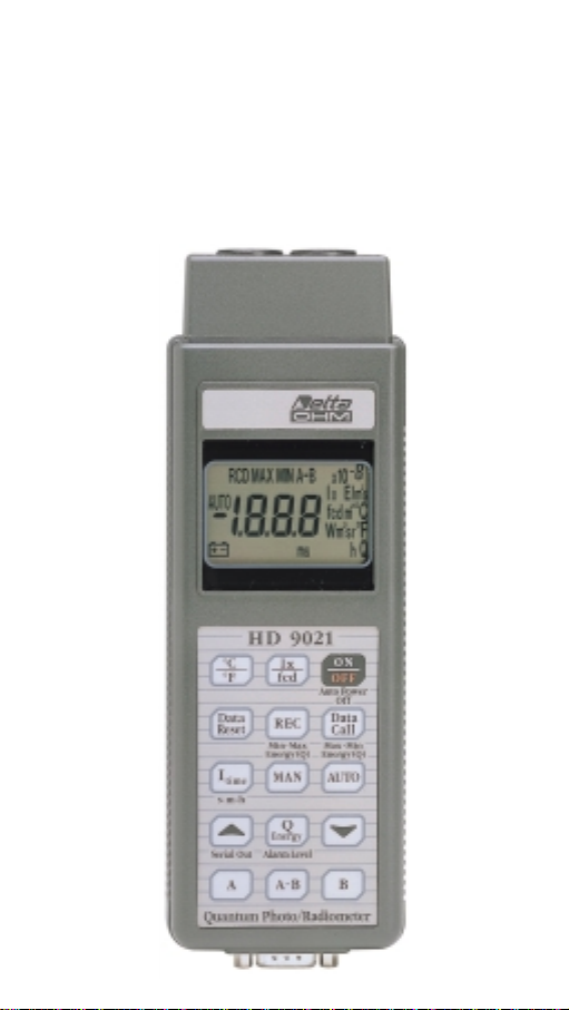
QUANTUM - PHOTO - RADIOMETER
Page 4
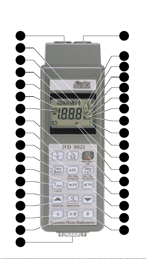
1 Input A socket, DIN 8-pole connector
2 Display
3 REL: the symbol indicates that the instrument is storing the Maximum, Minimum
and Q energy values
4 MAX: the symbol indicates the maximum value of the chosen unit
5 MIN: the symbol indicates the minimum value of the chosen unit
6 A, B, A-B: the symbol indicates the relative value at the input A, B, or the differen-
ce between the two inputs A-B
7 AUTO: the symbol indicates that the automatic change of scale device is enabled
8 °C/°F: key for selecting temperature reading in °C or °F
9 lx/fcd: key for selecting reading in lx=lux or fcd=footcandle
10 Data reset: the key erases the memory of the maximum, minimum and Q energy
values and the integration time
11 REC: when this key is pressed, the maximum, minimum and Q energy values and
the integration time in seconds, minutes, hours, are stored and updated
12 Itime: when this key is pressed in sequence, the integration time that has elapsed
appears on the display in s=seconds, m=minutes and h=hours
13 MAN: key for choosing the working scale manually
14S, Serial out: the key has two functions. The first of these, when pressing the Q
key, makes the value advance towards the top of the acoustic alarm signal intervention threshold, the second enables the serial output for one item only and, if
pressed for more than 3 seconds, enables the serial output continuously with a
fixed rate of 10 seconds
15 Q energy: when the key is pressed, followed by the
S
and Gkeys, this sets the
threshold value above which the alarm intervenes
16 A: key for activating the display of input A
17 A-B: key for activating the display of the difference between inputs A and B
18 SUB D male 9-pole connector. The cable with electronics for the serial output
RS232C, code AD RS232C, may be coupled to this connector
19 Input B socket, DIN 8-pole connector
20 X10-8: multiplication factor for the chosen unit; this may be 10
3
, 106, -103, or -10
6
21 lx: symbol indicating that the reading is in lux
22 E/m-2•s: symbol indicating that the reading is in µEinstein
23 fcd/m2: symbol indicating that the measurement is in footcandle m
2
24 °C: symbol indicating that the temperature measurement is in °C
25 °F: symbol indicating that the temperature measurement is in °F
26 Wm2: symbol indicating that the measurement is in Wm
2
27 Q energy: symbol indicating the quantity of energy in the integration time X
28 m: integration time in minutes
29 s: integration time in seconds
30 h: integration time in hours
31 ON/OFF: key for switching the instrument on or off
32 DATA CALL: key for calling and reading on the display the stored maximum, mini-
mum and Q values
33 AUTO: this key enables the automatic change of scale function of the instrument
34G, after the Q energy key has been pressed, this key reduces the threshold value
above which the acoustic alarm intervenes
35 B: key for activating the display of input B.
ENGLISH
– 26 –
Page 5
ENGLISH
– 27 –
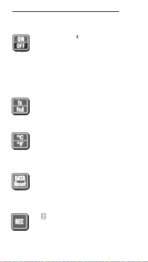
Symbols lit besides
the numbers
Key
Description
All the symbols are
lit for a few seconds
after switching on.
lx/fcd
°C/°F
RCD
K
Key for switching the instrument on
and off. The instrument switches off
automatically about 8 minutes after
this key has been pressed, as it has
a built-in switch-off device. If any
key other than the ON/OFF key is
pressed, the instrument switches
off 8 minutes after the last key was
pressed.
For measuring ILLUMINANCE;
when this key is pressed the reading may be in the photometric unit
lux or foot candle if a photometric
probe is fitted in the instrument.
If a temperature probe of the TP870
series is fitted in the instrument, this
indicates the temperature measured by the probe. The key may be
pressed alternately to give a reading in °C or °F.
When the key is pressed it erases
from the memory and resets the
maximum, minimum and integrated
Q energy values, then resets the
count of the time elapsed.
When the key is pressed the instrument stores and updates the maximum, minimum and integrated Q
energy values for the time elapsed,
recorded by the measurement probe fitted. The battery symbol fla-
Page 6
shes.
During the RCD phase the AUTOPOWER-OFF function is disabled,
that is the instrument does not switch off automatically. To switch off,
press the ON/OFF key. If the stored
data are not reset they remain in
the memory until REC is pressed
again. When the key is pressed for
the first time it starts storing data in
the memory, the second time it stops data storage (the data stored so
far are not erased), the third time it
restarts storage and updates the
data.
When the key is pressed during
RECORD phase or at the end of Q
RECORD, before the DATA RESET
key is pressed, the display shows in
sequence the maximum value recorded by the probe, the minimum
value, the Q Energy value and finally
the current value. If the DATA
RESET key has been pressed, the
"Err" message appears on the
display, referring to the maximum,
minimum and Q Energy values.
When the AUTO key is pressed the
instrument chooses what scale to
operate on. Change of scale is
automatic.
ENGLISH
– 28 –
MAX
MIN
AUTO
Symbols lit besides
the numbers
Key
Description
Page 7
When the MAN key is pressed the
user chooses what scale to operate
on. There are 4 scales available,
except for temperature measurement where there are 2.
When this key is pressed the Q
Energy integration time that has
elapsed since the REC key was
pressed appears on the display in
seconds, minutes or hours.
To quit the routine, press the key
for the channel in which the reading
is being taken.
When this key is pressed followed
by the 1and 2keys, it sets the
maximum value of the Q Energy
threshold above which a buzzer
sounds to indicate that the set threshold has been reached. When
pressed for the second time it indicates the set threshold.
The value goes from 0 to 1999,
then continues with 103and 106. Q
Energy calculation begins when the
REC key is pressed and continues
until it is interrupted by pressing
REC again. When the set threshold
is exceeded the internal buzzer
sounds intermittently as long as the
instrument is in record mode.
NOTE: When setting the alarm
threshold, if the keys and 1(or
2
) are pressed simultaneously, this
makes the value on the display
advance faster. This may be useful
ENGLISH
– 29 –
s
m
h
MAX - Q
Symbols lit besides
the numbers
Key
Description
Page 8

if a high value is to be set.
This key has two functions; in the
first, when Q is set, it increases the
value; the second function enables
the serial output. When the key is
pressed only once, the figure
shown on the display is sent to the
serial output. If the key is pressed
for more than three seconds the
continuous serial output is enabled;
this means that what is shown on
the display is sent continuously to
the serial output every 10 seconds.
To quit, press the 1key.
During Q setting the serial output is
disabled.
During setting of the maximum Q
threshold this key is used to
decrease the set value.
Key for selecting the input A probe,
if the probe is not inserted the "Err"
message appears.
Key for selecting the input B probe,
if the probe is not inserted the "Err"
message appears.
Key for displaying the difference in
value between inputs A and B; if no
probe is inserted, or if the probes
are of a different type, the message
E1 appears.
ENGLISH
– 30 –
Symbols lit besides
the numbers
Key
Description
A
B
A-B
Page 9

ENGLISH
– 31 –
PROBE CONNECTION
The HD 9021 may be fitted with either one or two probes; the instrument
has two DIN 45326 8-pole inputs, input A and input B. If only one input is
used, be careful when using the keys for input A or B.
The instrument recognizes the type of probe connected, which is distinguished by a suitable code; it then gets ready to take the measurement according to the characteristics of the probe connected. The connectors are
polarized and it takes a certain effort to insert or remove them; proceed in
such a way as to avoid damaging the connector, do not pull the cables to
disconnect the probe as there would be a risk of tearing them.
HOW TO MEASURE
Press the ON/OFF key to switch on the instrument. If the probes are connected, the instrument is ready to indicate their value. The instrument may
be fitted with probes for measuring temperature (°C, °F), probes for photo-
metric measurements (lux, fcd) or radiometric probes (W/m2). When the
instrument is switched on the auto-power off device is activated; this
means that the instrument switches off automatically after 8 minutes
unless another key is pressed. If the instrument switches off automatically
while a measurement is being taken it is sufficient to switch it back on.
Measurements are taken by positioning the probe in the desired point; the
choice of the type of probe, the position and place depend on the type of
recording that the user intends to make.
The operator must be sure that his own presence, foreign bodies or outside sources do not interfere with the recording.
If the probe is not connected to the
instrument when it is switched on, or
if there is a break in the probe, the
"Err" message appears.
This message appears on the
display when the user tries to obtain
the difference between inputs A and
B when two probes of different types
are connected.
This symbol appears on the display
when the reading is out of scale.
Symbols lit besides
the numbers
Key
Description
Err
E1
OFL
Page 10

The light emitted by a lamp varies with the square of the current, so there
may very well be variations in values during the test which the human eye
does not detect.
When measuring temperature choose the probe most suited for the case:
immersion, penetration or surface probes. It is sufficient to immerse the
probe in the liquid of which you want to measure the temperature or place
in contact with the surface; in the case of penetration probes, the tip of the
probe must penetrate the block in which the temperature is to be measured.
METHOD OF USE
Although the probes are sturdy, they must be used with due care so as to
avoid spoiling, scoring or breaking the filters or diffusors. Do not use them
at temperatures higher than 50°C; be careful when there is a concentration
of luminous beams or arc lights.
- Do not use the probes in the presence of corrosive gases or liquids or
immerse them in liquids unless they are made for these purposes.
- Always use the most suitable probe for the measurement to be taken.
- Be careful with the range of use of the probe.
- Always clean the probes carefully after use.
- The instrument is resistant to water but it is not watertight, so if it should
fall into the water, take it out immediately and check that no water has
infiltrated.
ENGLISH
– 32 –
Page 11

LOW BATTERY WARNING
If the battery voltage falls below
acceptable levels, a beep sounds
every 30 seconds and the
H
symbol appears. From that
moment there remains about 1
hour autonomous operation,
however the battery should be
replaced as soon as possible.
To change the battery turn the
screw on the door of the battery
compartment in an anti-clockwise
direction.
After replacing it (with an ordinary
9V battery IEC 6LF22) close the
door, inserting the tag on the door
into the slot provided, and turn the
screw in a clockwise direction.
Ensure that the instrument is
switched off before changing
the battery.
FAULTY OPERATION WHEN SWITCHING ON AFTER CHANGING THE
BATTERY
If the instrument does not switch on or off after changing the battery,
repeat the battery changing procedure, waiting for a few minutes after
removing the battery to allow the circuit condenser capacities to be completely discharged, then insert the battery.
Check that the battery you are using is really efficient; sometimes unused
batteries have not been recently manufactured so, due to the auto-discharge phenomenon, their voltage level is insufficient for correct operation of
the instrument.
WARNING
*
If the instrument is not to be used for a long period the battery should be
removed.
*
If the battery is flat it must be replaced immediately.
*
Avoid leakage of fluid from the battery.
*
Always use good quality watertight batteries.
ENGLISH
– 33 –
Page 12

MAINTENANCE
Storage conditions.
*
Temperature: -20 to +60°C
*
Humidity: less than 85% relative humidity.
*
Do not store the instrument in places where:
1 - There is a high degree of humidity.
2 - The instrument is exposed to direct sunlight.
3 - The instrument is exposed to a source of high temperature.
4 - There are strong vibrations.
5 - There is steam, salt and/or corrosive gas.
The instrument body is made of plastic so it must not be cleaned with solvents which can spoil plastic.
SERIAL OUTPUT
To enable the serial output of the instrument proceed as follows:
1. Insert the SUB D female 9-pole connector of the adapter cable with elec-
tronics AD RS232C in the DIN 9-pole socket on the instrument.
2. Connect the SUB D female 25-pole connector of the fitting to the serial
input of the printer or computer. The position of the switch in the connector must be:
DCE: data communication equipment (Modem)
DTE: data terminal equipment (Computer)
3. If you want to send what is shown on the display (once only), press the
1
key until the instrument emits two beeps.
4. If you want to send what is shown on the display continuously, at a fixed
rate of once every 10 seconds, press the
1
key until the instrument
emits three beeps.
5. To disable the serial output in continuous transmission, press the
1
key
until the instrument does not emit a beep.
6. If the serial output is not being used it is advisable not to fit the cable
AD RS232C on the instrument, thus saving battery consumption.
7. Serial output: RS232C
Data transmission speed
300 baud
8 data bit length
1 start bit
1 stop bit
no parity
ENGLISH
– 34 –
Page 13

ANALOG OUTPUT
It is possible to link up with the SUB D male 9-pole connector of the instrument to obtain an analog output:
ENGLISH
– 35 –
DTE DCE
AD RS 232C
- Data terminal equipment
DTE
COMPUTER
- Data communication equipment
DCE
MODEM
RTS
TXD
SCR
12345678910111213
14 15 16 17 18 19 20 21 22 23 24 25
NCTCNCRCNC
CTS
RXD
DSR
DCD
GND
NC
DTR
NCNCNCNCNC
NCNCNC
TEST
NC
12345678910111213
141516171819202122232425
12345
6789
1 2 3 4 5
6-8 = A
1-8 = B
BA
A= 1,9
250
B= 1,9
250
1 2 3 4 5
2,5
2,5
6 7 8 9
mV/°C
mV/lux
mV/W
mV/°C
mV/lux
mV/W
6 7 8 9
Page 14

ENGLISH
– 36 –
BLOCK DIAGRAM
DETECTOR
LOW VOLTAGE
KEYBOARD
TR1
POWER
SUPPLY
INPUT A
4V
CONNECTOR
(Range)
Probe Type
MICROPROCESSOR LCD
A/D
Signal
TR2
500 mV
CONVERTER
(Range)
Probe Type
Signal
RS232
INPUT B
CONNECTOR
Page 15

ENGLISH
– 37 –
LAYOUT OF COMPONENTS
TR2
C11
U4
U3
R40
R41
R30
R28
U2
C8
R17
R18
R38
C10
R32
TR2
C7
J3
C15
R23C5R33
R26
C9
R24
R16
R15
R37
X1
R9
R34
R4C6
R27
C13 C12
R39
C16
J4
R19
R12
R20
R14
U5
R1
R2
R45-51
J5
R33
R34
R23
B2
OUTB OUTA ICON1
R6
R6
R8
D1
C4
G2 G3
Q4Q1
C14
R11
R10
R29
TR1
TR1
DZ1
R5
R3
R4
R25
U1
C3
C2
C1
R36
R35
Page 16

CALIBRATING THE INSTRUMENT HD 9021
1) Open the instrument.
2) Connect the prods of a precision meter to the following pins on the input
A (or B) connector: the positive to pin 7 (V+) and the negative to pin 6
(GND).
3) With the instrument and the meter switched on, turn the trimmer TR1
until the display on the meter indicates 4Vdc.
4) Insert the photometric simulator in the connector A (or B).
5) Turn the trimmer TR2 until the display on the instrument shows the
same value as the simulator.
SERIES HD 9021 PROBE CALIBRATION
1) Fit the probe in the instrument.
2) Fit the probe in the photometric bench.
3) Turn the trimmer T1 of the amplification and calibration circuit in the pro-
be connector until the value shown on the display coincides with the
value of the reference instrument.
GUARANTEE
This instrument is strictly inspected before being sold. However if there
should be any defect due to manufacture and/or transport, apply to the
dealer from whom you bought the instrument.
The guarantee period is 2 (two) years from the date of purchase. During
this period all defects found by us will be repaired free of charge, exclu-
ding those due to incorrect use and careless handling. The probes
are not covered by the guarantee, as they can be irreparably damaged after only a few minutes of incorrect use.
ENGLISH
– 38 –
25
DIN8P
R6
R3
U1
8
R1
TR1
R2
R8 C2
HOLE
AC
R10C3
U2
R9 R7 R5 R4 C1
T1
Page 17

ENGLISH
– 39 –
CHARACTERISTICS
- Microprocessor-controlled multifunction quantum-photo-radiometric indi-
cator with LCD indication for measuring sources of light and temperature.
Measures ILLUMINANCE (lux, foot-candle), IRRADIANCE (W/m
2
) and
RADIANCE (cd/m2).
- 2 inputs for probes and one for RS232C (with an optional adapter
AD RS232C).
- Probe connection: 2 DIN 45236 8-pole sockets.
- Different silicon sensors for various types of measurement.
- Spectral response:
photometer 400÷760 nm photopic curve according to CIE (1924)
radiometer 190 nm - 3.5 micron
- Conversion frequency: 1 per second.
- Integration time: from 1 second to 1999 hours.
TECHNICAL FEATURES
Measurements and measuring ranges:
- Photometer: Spectral range 400÷760 nm, automatic change of scale or 4
manual scales from 0 to 200,000 lx (0÷200,000 fcd). For
measuring ILLUMINANCE.
- Radiometer: Spectral range 400÷900 nm, measurements from
1 microwatt/cm2to 200 mW/cm2. For measuring IRRADIANCE.
- UVA: Spectral range 315÷400 nm, peak at 365 nm, measurements from
10 nanowatt/cm2to 200 mW/cm2. For measuring IRRADIANCE.
- UVB: Spectral range 280÷315 nm, peak at 312 nm, measurements from
10 nanowatt/cm2to 200 mW/cm2. For measuring IRRADIANCE.
- UVC: Spectral range 190÷280 nm, peak at 250 nm, measurements from
10 nanowatt/cm2to 200 mW/cm2. For measuring IRRADIANCE.
- PAR (Photosintetically active radiation): Spectral range from 400 to
700 nm, measurement in microEinstein per square metre per
second, measuring range from 0 to 20,000 µE m-2•s-1.
- Luminance: Measuring range from 0 to 1999x10
3
cd/m2.
- Instrument precision: ±0.1 rdg ±1 digit with a reference temperature of
25°C ±5°C.
- Probe precision: Radiometric ±4%.
Photometric ±5%.
- Linearity: ±1%.
- Resolution: ≤200 = 0.1 : ≥200 = 1.
- Stability: 0.15%.
- Zero drift: ±0.05%/°C of reading.
- Working temperature: 0...50°C.
- Storage temperature: -20...+60°C.
- Relative humidity: 10÷85% RH.
Page 18

- Display: LCD 12 mm, function and photo-radiometric symbols.
- Functions: Automatic and manual change of scale, integration time up to
1999 hours, auto power off. Storage and updating of the
Maximum, Minimum and Q (Energy) values. Optoinsulated
serial output RS232C with adapter AD RS232C.
Analog output 1.9 mV/°C, 2.5 mV/lux, 250 mV/W.
- Power supply: 9V battery IEC 6LF22.
- Battery life: 150 hours with alkaline battery.
- Serial output: RS232C data transmission speed
300 baud 8 data bit length
1 start bit 1 stop bit
no parity
Use the optional adapter cable AD RS232C from SUB
D female 9-pole to SUB D female 25 pole connectors.
Manual or automatic transmission of the value displayed;
at a fixed rate of once every 10 seconds.
CHARACTERISTICS OF THE INSTRUMENT WHEN MEASURING TEMPERATURE WITH PROBES IN THE SERIES TP870
Measuring range: -200°C...+800°C (-392°F...+1472°F) in two scales with
automatic change of scale.
Resolution: -200°C...+200°C = 0.1, above that =1°C
Precision with TP870 probe included: -50°C...+200°C (-58°F...+392°F)
±0.15% ±0.2°C ±1 digit
over ±0.3% ±1°C ±1 digit.
At temperatures higher than 400°C, avoid violent blows or thermal shock to
the temperature probes as they may cause irreparable damage to the sensor.
Instrument container: ABS Bayer NOVODUR, black.
Weight of the instrument alone: 360 g
Weight of the kit: 2500 g
Dimensions of the instrument: 135x73x38 mm
Dimensions of the kit: 370x280x90 mm
ENGLISH
– 40 –
Page 19

ORDER CODE
HD 9021 K : The kit is composed of the HD 9021 instrument, diplomatic
carrying case, without probe.
HD 9021 : Photometric probe for measuring light, illuminance, photopic
PHOT/C correction filter complying with CIE, diffuser for cosine correc-
tion. Range 0÷200,000 lux.
HD 9021 : Radiometric probe for measuring light energy, irradiance,
RAD/C radiometric filter, diffuser for cosine correction.
Range 400÷900 nm.
HD 9021 : Radiometric probe for measuring radiations in the field of the
RAD/PAR PAR chlorophyll process (Photosynthetically Active Radiation
400÷700 nm), measurements in µEinstein, diffuser for cosine
correction.
HD 9021 : Radiometric probe for measuring radiation, irradiance, in the
RAD/UVA UVA wave length 315÷400 nm, peak at 365 nm. Quartz diffu-
ser for cosine correction.
HD 9021 : Radiometric probe for measuring radiation, irradiance, in the
RAD/UVB UVB wave length 280÷315 nm, peak at 312 nm. Quartz diffu-
ser for cosine correction.
HD 9021 : Radiometric probe for measuring radiation. irradiance, in the
RAD/UVC UVC wave length 190÷280 nm, peak at 250 nm. Quartz diffu-
ser for cosine correction.
HD 9021/Cd: Photometric probe for measuring luminance, photopic correc-
tion filter complying with CIE. Measuring range from 0 to
200 cd/cm2.
AD RS232C: Connecting cable from SUB D female 9-pole to SUB D female
25 pole, complete with electronics, for serial output RS232C.
TP 870 : Immersion temperature probe, Pt100 sensor, diam. 3x230 mm,
range -60°C...+400°C.
TP 870C : Surface temperature probe, Pt100 sensor, diam. 4x230 mm,
range -60°C...+400°C.
TP 870P : Penetration temperature probe, Pt100 sensor, diam.
4x150 mm, range -60°C...+400°C.
TP 870A : Air temperature probe, Pt100 sensor, diam. 4x230 mm, range
-60°C...+300°C.
ENGLISH
– 41 –
Page 20

PROBES
The primary purpose of the probes is to detect and measure light in its
various aspects; for this reason there are different probes available to suit
the different requirements. Probes are required for measuring illuminance
(lux, foot-candle), irradiance (W/m2) and luminance (cd/m2). Each sensor
has its own work band completed by filters or diffusors which correct or
limit its range. The size of the silicon sensor used in the various probes is
7.34 mm2. The probes are housed in a container of black anodized aluminium anticorodal UNI 9006/4; the correction filters are made of special
glass, while the diffusors are in quartz or plastic material specially designed for the purpose. The probe is complete with 2 metres of flexible cable
and a DIN 45236 8-pole connector inside which is an electronic circuit that
amplifies and codes the signal supplied by the sensor.
The probes are calibrated individually and are therefore interchangeable.
HD 9021 PHOT/C
Photometric probe for measuring light, ILLUMINANCE, photopic correction
filter complying with CIE, diffuser for cosine correction. Range
0÷200,000 lux (0÷200,000 foot candle). This is the probe for measuring
light with correction according to the human eye; it is suitable for measurements in offices, schools, laboratories, places of entertainment, emergency
exits, car parks, galleries, shops, shop windows, factories, etc., in all lighting measurements.
The typical response curve of the probe is
as follows:
ENGLISH
– 42 –
1.00
0.89
0.78
0.67
0.56
0.44
0.33
0.22
0.11
0.00
380.0
420.0
460.0
500.0
540.0
580.0
620.0
660.0
700.0
740.0
780.0
Page 21

HD 9021 RAD/C
Radiometric probe for measuring the IRRADIANCE of light sources, irradiance of the sun, etc. Radiometric filter and diffuser for angle correction
according to the cosine law. Spectral measurement range 400÷900 nm,
range from 1 microwatt/cm2to 200 milliwatt/cm2. The probe is used in
greenhouses for measuring the power of artificial light, shade, the performance of solar panels, solar heating plants, solar filters, etc.
The typical response curve of the probe is
as follows:
HD 9021 RAD/PAR
Radiometric probe for measuring PAR radiations (Photosynthetically Active
Radiation), works in the field of the chlorophyll process following a special
response curve in a spectral range from 400 to 700 nm. The measurements are expressed in µEinstein in the range 0÷20,000 µE m-2•s-1.
Photosynthetically Active Radiation, PAR. Flow of photons in the wavelength 400÷700 nm.
Photosynthetic photon flux density, PPRD. The number of photons per
time unit and air unit in the wavelength 400÷700 nm.
The measurement is expressed in micromoles per second and per square
metre. One mole is the equivalent of 6,0222•10
23
photons.
Correction filter according to the cosine law.
Typical applications of the probe are for research in the field of greenhouse
lighting, research in undergrowth, etc.
ENGLISH
– 43 –
1.00
0.90
0.80
0.70
0.60
0.50
0.40
0.30
0.20
0.10
380.0
460.0
540.0
620.0
700.0
780.0
860.0
940.0
1020
1100
Page 22

The typical response curve of the probe is
as follows:
The study and field of application of ultraviolet rays has seen considerable
growth in the last decades. The ultraviolet field is conventionally subdivided into the following three "bands":
- the band between the wavelengths from 400 to 315 nm. which includes
radiations defined as type A or UVA;
- the band between the wavelengths from 315 to 280 nm. which includes
radiations defined as type B or UVB;
- the band between the wavelengths from 280 to 100 nm. which includes
radiations defined as type C or UVC.
The ultraviolet rays in natural light as it reaches earth through the atmosphere are of type A.
The amount of UVA in natural light is much greater than that emitted by
traditional, incandescent bulbs, halogen or fluorescent lamps.
Save in the case of prolonged exposure, UVA rays possess a marked tanning action; they are not harmful to man but they may give rise to biological
effects that may be beneficial for his health. The problem is the time of
exposure; in fact, UVA rays have a considerable photochemical action that
in the course of time produces phenomena of fading, cracking and decay.
Ultraviolet rays of type B or UVB have the property of encouraging the formation of vitamin D, but unless suitable precautions are taken they may
cause erythema or conjunctivitis. The amount of UVB rays emitted by traditional lamps is very little in comparison with that emitted by sunlight and
they are also much less than UVA rays.
ENGLISH
– 44 –
1.00
0.89
0.78
0.67
0.56
0.44
0.33
0.22
0.11
0.00
400.0
450.0
500.5
550.0
600.0
650.0
700.0
750.0
800.0
850.0
900.0
Page 23

UVC rays are useful thanks to their bactericide and ozonizing capacity, so
they are used in the field of sterilization; another field of application that is
being developed is in the polymerization of adhesives or resins (photoresist); as a drawback they cause more serious cases of erythema and
conjunctivitis than UVB rays.
Depending on the effects that they produce, ultraviolet rays may also be
classified as follows:
Producing ozone in the field 180÷220 nm
Producing bactericide (germicide) action in the field 220÷300 nm
Producing erythematous action in the field 280÷320 nm
Black light in the field 320÷400 nm
HD 9021 UVA
Radiometric probe for measuring radiation power, IRRADIANCE, in the
UVA wave length 315÷400 nm, peak at 365 nm. Quartz diffuser for cosine
correction. Measuring range from 10 nanowatt/cm
2
to 200 milliwatt/cm2.
The typical response curve of the probe is
as follows:
ENGLISH
– 45 –
1.00
0.90
0.80
0.70
0.60
0.50
0.40
0.30
0.20
0.10
0.00
240.0
220.0
200.0
260.0
280.0
300.0
320.0
340.0
360.0
380.0
400.0
Page 24

HD 9021 UVB
Radiometric probe for measuring radiation power, IRRADIANCE, in the
UVB wave length 280÷315 nm, peak at 312 nm. Quartz diffuser for cosine
correction. Measuring range from 10 nanowatt/cm
2
to 200 milliwatt/cm2.
The typical response curve of the probe is
as follows:
HD 9021 UVC
Radiometric probe for measuring radiation power, IRRADIANCE, in the
UVC wave length 190÷280 nm, peak at 250 nm. Quartz diffuser for cosine
correction. Measuring range from 10 nanowatt/cm
2
to 200 milliwatt/cm2.
The typical response curve of the probe is
as follows:
ENGLISH
– 46 –
1.00
0.90
0.80
0.70
0.60
0.50
0.40
0.30
0.20
0.10
0.00
200.0
220.0
240.0
260.0
280.0
300.0
320.0
340.0
360.0
380.0
400.0360.0
1.00
0.90
0.80
0.71
0.61
0.51
0.41
0.32
0.22
0.12
220.0
200.0
240.0
260.0
280.0
300.0
320.0
340.0
Page 25

– 47 –
HD 9021/Cd
Probe for measuring LUMINANCE, measuring range from 0 to 1999x10
3
candles/cm2. Measuring angle 6° with opening surface 25 mm. CIE filter for
correction according to the human eye.
- The CANDLE (cd) is the light intensity in a specific direction of a source
that emits monochrome radiation at a frequency of 540x10
12
Hz and who-
se energetic intensity in that direction is 1/683 W/sr.
- The STERADIAN (sr) is the solid angle which, with its vertex in the cen-
tre of a sphere, subtends a spherical cap with an area equal to the square of the radius.
- LUMINANCE or EMITTANCE is the relationship between the light inten-
sity emitted in a certain direction and the surface that emits it projected
onto a plain perpendicular to the same direction; the measuring unit is the
cd/m2(candle/square metre) or its submultiple cd/cm2(1 cd/cm2=
10,000 cd/m2).
Light flux = lumen (lm) = cd/sr
Illuminance = lux (lx) = lm/m
2
Luminance = nit (nit) = cd/m
2
6°
Page 26

ENGLISH
– 48 –
CE CONFORMITY
Safety EN61000-4-2, EN61010-1 level 3
Electrostatic
discharge
EN61000-4-2 level 3
Electric fast
transients
EN61000-4-4 level 3
Voltage variations EN61000-4-11
Electromagnetic
interference IEC1000-4-3
sucseptibility
Electromagnetic
interference EN55020 class B
emission
GUARANTEE CONDITIONS
All our appliances have been subjected to strict tests and are guaranteed for 24 months from date of purchase. The Company undertakes to repair or replace free of charge any parts which it considers to be inefficient within the guarantee period. Complete replacement of the instrument is excluded and no requests
for damages are recognized, whatever their origin. Repairs are carried out in our own Technical Service
Department. Transport expenses are borne by the buyer. The guarantee does not include: accidental
breakages due to transport, incorrect use or neglect, incorrect connection to voltage different from
that contemplated for the instrument, probes, sensors, electrodes and all accessories. Furthermore
the guarantee is not valid if the instrument has been repaired or tampered with by unauthorized third parties, or adjusted for faults or casual checking. The guarantee is valid only if all parts of the guarantee card
have been filled in. Any instruments sent for repairs must be accompanied by their guarantee certificate.
For all disputes the competent court is the Court of Padua.
DELTA OHM SRL
VIA G. MARCONI, 5 - 35030 CASELLE DI SELVAZZANO (PD) - ITALY
TEL. 0039-0498977150 r.a. - FAX 0039-049635596
e-mail: deltaohm@tin.it - Web Site: www.deltaohm.com
SIT CALIBRATION
CENTRE N° 124
 Loading...