

Page 1
FC310
p
FIBRE CHANNEL BRIDGE QUICK REFERENCE GUIDE
This Quick Reference Guide
explains how to install the FC310
in a Quantum|ATL M-Series tape
library.
For your convenience, this task
has been condensed into a few
simple steps. As you perform each
step, watch for instructions that
specifically address a first-time
installation or a field replacement.
If you need help with any part of
these instructions, please contact
Quantum|ATL Customer Support
24 hours a day, 7 days a week, at
the number for your area listed in
the M1500 Library User’s Guide.
You can also receive help in the
form of a complete set of M1500
user documents in Portable
Document File (PDF) format by
going to www.QuantumATL.com.
Once the FC310 is installed, it
must be configured using
instructions foundin the
Quantum|ATL FC310 Bridge
User’s Guide (PN 6421018). This
User’s Guide and other applicable
documentation are available in
PDF format on the CD shipped in
the FC310 Upgrade/FRU Kit.
NOTE: Adobe Acrobat Reader is
required to view and print PDF
documents. To download a free
copy of Adobe Acrobat Reader,go
to www.adobe.com.
STEP 1: PREPARE FOR INSTALLATION/REPLACEMENT
a. If this is a first-time installation, make sure you have the following system
requirements:
-- A server or Quantum|ATL-approved Fibre Channel hub or switch with an
appropriate connection topology (fabric, loop, or point-to-point)
-- A Quantum|ATL-approved Fibre Channel host bus adapter (HBA)
configured for the correct topology.
-- Compatible Fibre Channel cable connectors. The FC310 has an SC type
Fibre Channel connector, which is designed to accommodate 50-micron or
62.5-micron multimode fiber-optic cables. The 10-meter (32.8-foot) cable
supplied with the FC310 is a 62.5-micron fiber-optic cable.
-- Quantum|ATL-approved network management software package.
-- Quantum|ATL approved operating system (Windows
Windows 2000 SP2, Solaris
b. Make sure you have the tools and equipment recommended for this procedure:
-- #1 Phillips screwdriver.
-- Flat-blade screwdriver.
-- A personal computer such as a laptop with a standard, 9-pin, D-type serial
port and HyperTerminal or equivalent.
c. Check the FC310 kit using the Quantum|ATL FC310 Contents List.
d. Take precautions to prevent electrostatic discharge (ESD). These precautions
include:
-- Wearing a properly grounded antistatic wrist strap.
-- Wearing other antistatic apparel (smock, footwear, etc.).
-- Keeping the FC310 in its antistatic packaging until you are ready to
configure and install it.
CAUTION: Failure to take adequate antistatic precautions may result in
damage to the FC310 card or other library components.
®
8, etc.).
®
NT 4.0 SP6,
Page 2
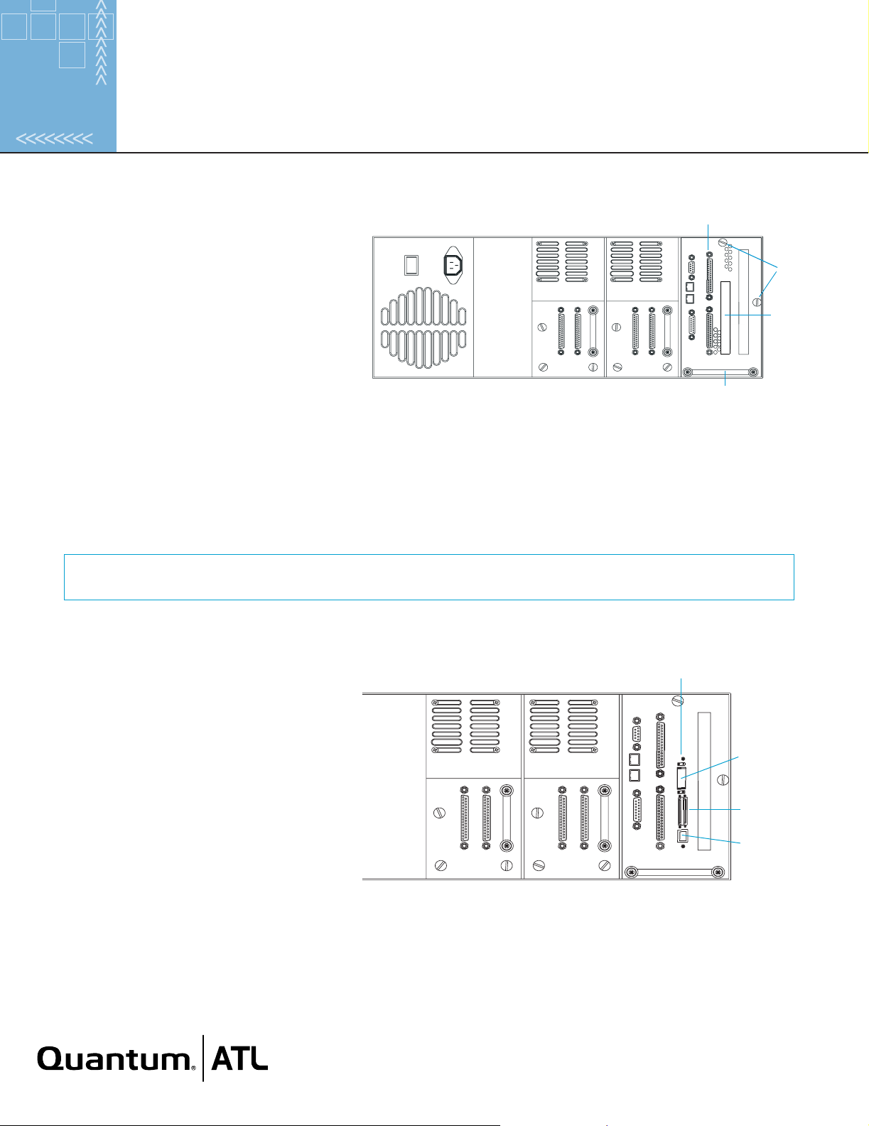
STEP 2: INSTALL THE FC310
SCSI controller
a. Turn off and unplug the library. (If this is a
standalone library, remove the two screws
holding the library cover in place and slide the
Captive
screws
cover off.)
b. Loosen the two captive screws that secure the
Slot for
FC310
card cage to the back of the library.
c. Slide the card cage out of the library using the
handle.
d. Locate the expansion slot closest to the SCSI
adapter.
M-Series Library Back Panel
Handle
If this is a first-time installation, remove the slot cover plate and hold-down clamp. To do this, remove the screws
securing the cover plate to the card cage and then lift the plate out. Remove the screws that secure the hold-down
clamp to the side of the card cage. Save the clamp for use later in this installation. Save the cover plate for future use.
IfyouarereplacinganFC310,remove the existing FC310 by detaching all cables, removing the hold-down clamp
screws from the side of the card cage, removing the screws that secure the FC310 to the card cage, and then lifting the
FC310 out of the expansion slot.
NOTE: Refer to the Return Material Authorization (RMA) documents shipped with the replacement FC310 Bridge
kit for the appropriate return procedure.
e. Carefully remove the new FC310 from its antistatic packaging. Hold the FC310 by the edges; avoid contact with FC310
components and connectors.
f. Insert the FC310 into the expansion slot.
Press down gently on the card edge until the
card is securely seated.
g. Secure the FC310 to the card cage frame
using the two screws provided.
h. Reattach the hold-down clamp to secure the
card in the slot.
i. Slide the card cage back into the library and
securethecagebytighteningthetwocaptive
screws.
j. If this is a standalone library, slide the cover
back on the library and secure it in place.
FC310
Fibre
Channel port
SCSI ports
Serial port
(RJ45)
M-Series Library BackPanel with FC310 Installed
Page 3

STEP 3: CONNECT SCSI CABLES
a. Attach a SCSI cable from the upper SCSI port on the library SCSI
controller to the first SCSI connector on drive 0. Terminate the
second SCSI connector on drive 0.
Drive 0
SCSI cable
(controller
to drive 0)
b. Attach a SCSI cable from SCSI port 0 on the FC310 (the left VHDCI
connector) to the lower SCSI port on the library SCSI controller.
c. If the library has two drives, attach a SCSI cable from SCSI port 1 on
the FC310 (the right VHDCI connector) to the first SCSI connector on
drive 1. Terminate the second SCSI connector on drive 1.
STEP 4: CONNECT THE FIBRE CHANNEL CABLE
a. Connect one end of the Fibre Channel cable to the Fibre Channel
port on the FC310.
b. Connect the other end of the Fibre Channel cable to the Fibre
Channel port on an HBA installed in a host computer, or to a switch or
hub.
STEP 5: STARTING UP/SELF-TESTING THE FC310
a. Using the serial cable provided, establish a connection between the
serial (RJ45) connector on the FC310 and the COM port (DB9) of the
external host computer.
b. Reconnect the library’s power cord to a grounded power outlet and
then turn on the library.
c. When the library has powered up, turn on the host computer.
d. Make sure the COM port on the host computer has the following
settings:
Terminator
C310 SCSI Cabling—One-Drive Library
Drive 1 Drive 0
Terminators
FC310 SCSI Cabling—Two-DriveLibrary
SCSI port 0
SCSI port 0
SCSI cable
(FC310 to
controller)
SCSI cable
(FC310 to
drive 1)
SCSI
port 1
-- Baud rate: 9600
-- Data bits: 8
-- Parity: None
-- Stop bits: 1
-- Flow control: None
e. Run HyperTerminal or equivalent.
Page 4

f. At the Ready prompt, type firmwarerestart and press <Enter>. This causes the firmware to restart and the power-on self-
test (POST) to run. During POST, make sure that all SCSI port initiator IDs are present and all status messages appear
normal.
Ready prompt reappears when POST is completed.
The
NOTE: If POST messages do not appear, check all connections and COM port settings. Power cycle the library and
verify that the green “Ready” LED above the Fibre Channel port is on steady. Then repeat the startup procedure.
STEP 6: CONFIGURE THE FC310
A command-line interface (CLI) is available to assist with FC310 configuration and maintenance as well as system diagnostics.
Specifically, the CLI can be used to configure the serial, Fibre Channel, and SCSI ports; to create device maps; to obtain FC310
status information; to log FC310 events; and to report SCSI and Fibre Channel device information.
For more information, refer to the Quantum|ATL FC310 Bridge User’s Manual (PN 6421018).
CORPORATE HEADQUARTERS
141 Innovation Drive
Irvine, CA 92612-3040
USA
Telephone: (949) 856-7800
Fax: (949) 856-7799
www.QuantumATL.com
Copyright 2001 ATL Products, Inc. All rights reserved. Prism is a trademark of ATL Products, Inc. in the United States and other countries. Adobe and Acrobat are trademarks of
Adobe Systems Incorporated, which may be registered in certain jurisdictions. All other trademarks are the property of their respective companies. Quantum|ATL is the generally
known alternative designation of ATL Products, Inc. Specifications are subject to change without notice.
6473010v1r0 6207947-04sN 02
EUROPEAN HEADQUARTERS
7 Lindenwood
Chineham Business Park
Basingstoke, RG24 BWD
United Kingdom
Telephone: +44 1256 818300
Fax: +44 1256 848700
ASIA PACIFIC HEADQUARTERS
1st Floor Honda House
I80 Kingsford Smith Drive
Albion, Old 4010
Brisbane, Australia
Telephone: +61 7 3862 4655
Fax: +61 7 3862 4677
Quantum|ATL maintains offices throughout the
USA, Europe, and Asia
 Loading...