

Page 1

Quantum PX500 Series
FC1202 Upgrade Instructions
Introduction 3
Fibre Channel Description .......................................................................................3
FC1202 Bridge Operation .........................................................................................3
Preparing for the FC1202 Installation 4
Required Upgrade Kits.............................................................................................4
Required Tools ...........................................................................................................4
FC1202 Upgrade Procedure 5
Preparing the Quantum PX500 Series Library ......................................................5
Removing Tape Drive SCSI Jumper Cables...........................................................6
Installing the FC1202 Bridge....................................................................................9
Installing the Ethernet Cables................................................................................13
Installing SCSI Jumper Cables...............................................................................18
Configuring the FC1202 Bridge Software ............................................................20
Saving the Configuration File................................................................................26
Enabling Serverless Backup (Xcopy) ....................................................................28
Zoning the Ethernet Switch 30
Connecting to the Ethernet Switch........................................................................30
Zoning the Ethernet Switch ...................................................................................31
81-81351-01 A01, June 2005 1
Page 2

Quantum PX500 Series FC1202 Upgrade Instructions
81-81351-01 A01
June 2005
2
Page 3

Quantum PX500 Series FC1202 Upgrade Instructions
81-81351-01 A01
June 2005
Introduction 0
The Quantum PX500 Series automated tape libraries are controlled by a host
computer via a SCSI LVD bus using the SCSI-3 medium changer command
set.
The Quantum PX500 Series allows for easy conversion from the SCSI host
interface to a Fibre Channel host interface. This document describes
upgrading a standard PX500 library equipped with a SCSI host interface to a
Fibre Channel host interface using a FC1202 Upgrade kit.
Fibre Channel Description
FC1202 Bridge Operation
Fibre Channel is a serial data transfer architecture for use with computers and
0
0
mass storage devices that is rapidly emerging to challenge SCSI as the
interface of choice for host-to-storage applications.
Fibre Channel advantages include:
• Connection distances with the Quantum FC1202 option up to 500 meters
• 1 GB/Sec, 2 GB/Sec, or autosense data transfer rates
• Supports up to 126 devices in a loop mode
• Supports 24-bit addressing for over 16 million devices in point-to-point
mode or fabric, when using a Fibre Channel switch or multiple Fibre
Channel switches.
• Operating system independence
• Interconnect flexibility
Once a FC1202 bridge option is installed and tested, the library operates
exactly as a PX500 Series with a SCSI host interface. Operation of the library
via the operator control panel (OCP) is unchanged.
Introduction 3
Page 4

Quantum PX500 Series FC1202 Upgrade Instructions
81-81351-01 A01
June 2005
Preparing for the FC1202 Installation 0
Before beginning the installation procedure, make sure that you have the
required upgrade kit and tools.
Required Upgrade Kits 0 The FC1202 installation requires the following upgrade kit for every two tape
drives in a PX500 Series library (see table 1
Note: All part numbers are subject to change without notice.
):
Table 1 FC1202 Upgrade
Kit PN PR-UU9CF-YF
Table 2 FC1202 Ethernet
Switch Upgrade Kit
PN PR-UUZZYF
Qty Description
1 FC1202-LVD PWA
2 SCSI Cables
1Ethernet cable
1 Quantum PX500 Series FC1202 Upgrade Instructions
The FC1202 Ethernet switch upgrade kit (see table 2) is only required if
multiple FC1202 Fibre Channel bridges are installed in either a PX506 or
PX510 library:
Qty Description
1 24 port Ethernet switch
4 Ethernet cables
1Power cable
1Serial cable
Required Tools 0 The following tools are required to install the FC1202 bridge upgrade:
• #2 PHILLIPS® screwdriver
4 Preparing for the FC1202 Installation
Page 5

Quantum PX500 Series FC1202 Upgrade Instructions
81-81351-01 A01
June 2005
FC1202 Upgrade Procedure 0
The upgrade procedure is identical regardless of the number of FC1202s
installed except where noted. The upgrade procedure consists of the
following major steps:
• Preparing the Quantum PX500 Series Library
• Removing Tape Drive SCSI Jumper Cables
• Installing the FC1202 Bridge
• Installing the Ethernet Cables
• Installing SCSI Jumper Cables
• Configuring the FC1202 Bridge Software
Preparing the Quantum PX500 Series Library
Figure 1 Operations
Screen
To prepare the PX500 Series library:
0
Caution: Use appropriate ESD procedures when assembling and
installing the FC1202 option.
1 With the library turned on, press the
Operations screen (see figure 1).
Press
Ops button on the OCP to access the
2 Select Library operations and press Enter.
3 From the library operations menu, select
Library on/offline and press Enter
to turn the library offline.
4 Verify that the OCP display indicates “Offline” from the
OCP screen.
5 Turn off the power button located on the front of the library (see figure 2
FC1202 Upgrade Procedure 5
).
Page 6

Quantum PX500 Series FC1202 Upgrade Instructions
81-81351-01 A01
June 2005
Figure 2 Turning On the
Library
Power button
OCP
Removing Tape Drive SCSI Jumper Cables
Each pair of tape drives within the library are connected via a SCSI jumper
0
cable. These cables must be removed prior to cabling the FC1202.
1 Locate the SCSI jumper cables connecting each pair of tape drives in the
library and the host systems (see figure 3
and figure 5
for PX510). The tape drives are numbered 1 through 10
for PX502, figure 4 for PX506,
(depending on library model) starting in the top-left drive bay. Tape drive
1 is in the upper right-hand drive bay, tape drive 2 is in the upper lefthand drive bay, and so forth. Refer to the following illustrations for exact
tape drive numbering.
6 FC1202 Upgrade Procedure
Page 7

Figure 3 PX502 Cabling
Configuration
Quantum PX500 Series FC1202 Upgrade Instructions
81-81351-01 A01
June 2005
Host computer
Tape drive 2 Tape drive 1
Figure 4 PX506 Cabling
Configuration
Host computer
SCSI jumper
Host computer
SCSI
jumpers
Tape drive 2 Tape drive 1
Tape drive 4
SCSI
terminator
SCSI
jumper
Tape drive 3
SCSI
terminators
SCSI jumper
Host computer
Tape drive 6
Tape drive 5
FC1202 Upgrade Procedure 7
Page 8

Quantum PX500 Series FC1202 Upgrade Instructions
81-81351-01 A01
June 2005
Figure 5 PX510 Cabling
Configuration
SCSI jumper
SCSI
jumper
Tape drive 2 Tape drive 1
Host computer
Host computer
Host computer
Host computer
SCSI
jumper
Host computer
Tape drive 4
Tape drive 6
Tape drive 8
Tape drive 10
Tape drive 3
Tape drive 5
Tape drive 7
Tape drive 9
SCSI
terminators
SCSI
jumper
SCSI
terminators
SCSI
jumper
2 Remove all SCSI jumper cables connecting each pair of tape drives and
the host systems and also all terminators.
8 FC1202 Upgrade Procedure
Page 9
Quantum PX500 Series FC1202 Upgrade Instructions
81-81351-01 A01
June 2005
Installing the FC1202 Bridge
The number of FC1202 bridges required depends on the number of tape
0
drives installed in the library.
• 1 to 2 tape drives requires 1 FC1202
• 3 to 4 tape drives requires 2 FC1202 bridges (PX506 and PX510 only)
• 5 to 6 tape drives requires 3 FC1202 bridges (PX506 and PX510 only)
• 7 to 8 tape drives requires 4 FC1202 bridges (PX510 only)
• 9 to 10 tape drives requires 5 FC1202 bridges (PX510 only)
To install the FC1202 bridge:
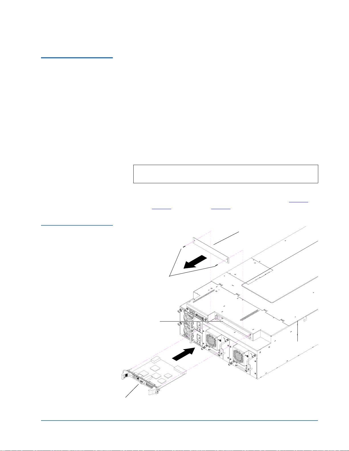
1 Loosen the two PHILLIPS screws securing the blank off plate(s) to the
CPCI card cage and expose the number of slots needed for the FC1202
installation (one blank off plate per FC1202).
Note: Start the FC1202 installation in slot 1 of the CPCI card cage
(PX506 and PX510 only).
2 With the SCSI ports located to your right as you face the back of the
library, slide the first FC1202 into the slot of the card cage (see figure 6
PX502, figure 7
for PX506, and figure 8 for PX510).
for
Figure 6 Installing a
FC1202 Bridge (PX502)
Blank off plate
Screws
Card cage
FC1202
FC1202 Upgrade Procedure 9
Page 10

Quantum PX500 Series FC1202 Upgrade Instructions
81-81351-01 A01
June 2005
Figure 7 Installing a
FC1202 Bridge (PX506)
Blank off plate
Screws
Card cage
Slot 1
FC1202
10 FC1202 Upgrade Procedure
Page 11
Quantum PX500 Series FC1202 Upgrade Instructions
81-81351-01 A01
June 2005
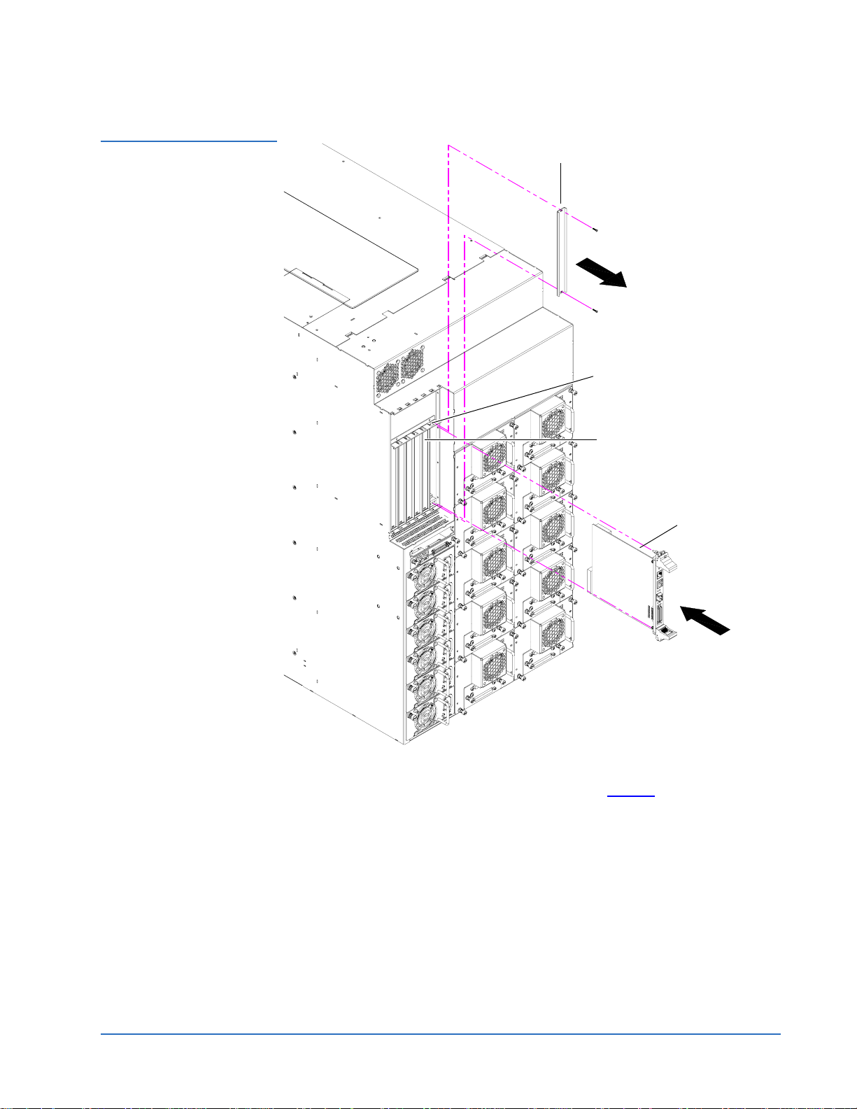
Figure 8 Installing a
FC1202 Bridge (PX510)
Blank off plate
Card cage
Slot 1
FC1202
3 Gently press down on the FC1202 until the board is seated in the card
cage and the ejector latches lock in place (see figure 9
FC1202 Upgrade Procedure 11
).
Page 12

Quantum PX500 Series FC1202 Upgrade Instructions
81-81351-01 A01
June 2005
Figure 9 Seating the
FC1202 Bridge
PX502 shown
Ejector latches in
locked position
Ejector latches
Figure 10 Securing the
FC1202 Bridge
4 Secure each bridge to the CPCI card cage by tightening the captive screws
located in the ejector latches with a PHILLIPS screw driver (see figure 10
Captive screws
PX502 shown
5 Repeat step 2 through step 4 for additional FC1202 bridges if necessary,
using the next available card cage slot.
).
12 FC1202 Upgrade Procedure
Page 13

Quantum PX500 Series FC1202 Upgrade Instructions
81-81351-01 A01
June 2005
Installing the Ethernet Cables
Figure 11 PX502 Ethernet
Connection
Depending on the library type, one or more Ethernet connections must be
0
made to the FC1202 Fibre Channel bridge. Refer to the following section for
your specific library:
• PX502 Ethernet Connections
• PX506 and PX510 Ethernet Connections
PX502 Ethernet Connections 0
PX502 libraries with installed FC1202 Fibre Channel bridges must have the
following Ethernet connections:
1 Connect a cross-over cable between the right port of the library system
controller board (SCB) and the FC1202 (see figure 11
Cross-over cable FC1202SCB (right port)
).
FC1202 Upgrade Procedure 13
Page 14

Quantum PX500 Series FC1202 Upgrade Instructions
81-81351-01 A01
June 2005
PX506 and PX510 Ethernet Connections 0
PX506 and PX510 require an Ethernet switch if more than one FC1202 is
installed in the library. Use the following procedure to install the Ethernet
switch and connect the Ethernet cables.
Note: If your PX506 or PX510 libraries have only a single FC1202 Fibre
Channel bridge, refer the PX502 Ethernet Connections
Ethernet cross-over cable is connected between the library SCB
and FC1202.
To install and cable the Ethernet switch:
1 Attach the mounting brackets to each side of the Ethernet switch with
four PHILLIPS screws on each bracket (see figure 12
. A single
).
Figure 12 Attaching the
Mounting Brackets to the
Ethernet Switch
Screws
Mounting bracket
Mounting bracket
Ethernet switch
Screws
2 Install the Ethernet switch directly above the PX506 or PX510 that
contains the FC1202s with two PHILLIPS screws on each side of the
switch (see figure 13
).
Note: If the libraries are in a multiple stack configuration, mount the
Ethernet switch directly above the top-most library.
14 FC1202 Upgrade Procedure
Page 15

Figure 13 Installing the
Ethernet Switch
Quantum PX500 Series FC1202 Upgrade Instructions
81-81351-01 A01
June 2005
Cable clamps (install
where necessary to
secure Ethernet cables
Ethernet switch
Screws
PX506 shown
3 Connect the following Ethernet cables:
• One Ethernet cable from the right port on the SCB to the Ethernet
switch (master library only).
• One Ethernet cable from each FC1202 to the Ethernet switch.
4 Secure the Ethernet cables with cable clamps and tie bands as needed (see
figure 14
for unstacked configurations and figure 15 for stacked
configurations).
Note: If possible, connect the SCB and FC1202 Ethernet connections
to the Ethernet switch in the following order:
• SCB connected to Ethernet switch port 1 (master library
only)
• First FC1202 to Ethernet switch port 2
• Second FC1202 to Ethernet switch port 3 and so forth....
This allows for easier maintenance and future FC1202
additions.
FC1202 Upgrade Procedure 15
Page 16

Quantum PX500 Series FC1202 Upgrade Instructions
81-81351-01 A01
June 2005
Figure 14 Connecting the
Ethernet Cables (Single
PX506/PX510 Library)
Cable clamps
Tie bands
Ethernet switch
FC1202 bridges
16 FC1202 Upgrade Procedure
PX506 shown
Page 17

Figure 15 Connecting the
Ethernet Cables (Stacked)
Cable clamps
Quantum PX500 Series FC1202 Upgrade Instructions
81-81351-01 A01
June 2005
Tie bands
Ethernet
switch
FC1202
bridges
Cable clamps
SCB connection
from master
library
FC1202
bridges
PX506s
shown
FC1202 Upgrade Procedure 17
Page 18

Quantum PX500 Series FC1202 Upgrade Instructions
81-81351-01 A01
June 2005
Installing SCSI Jumper Cables
Use the following procedure to connect the SCSI jumper cables and
0
terminators to the tape drives and FC1202(s).
• SCSI connectors 0 through 1 on the first FC1202 are used to connect to
tape drives 0 through 1 and the library robotics controller.
• SCSI connectors 0 through 1 on the second FC1202 are used to connect to
tape drives 2 through 3, if present.
• SCSI connectors 0 through 1 on the third FC1202 are used to connect tape
drives 4 through 5, if present.
• SCSI connectors 0 through 1 on the fourth FC1202 are used to connect
tape drives 6 through 7, if present.
• SCSI connectors 0 through 1 on the fifth FC1202 are used to connect tape
drives 8 through 9, if present.
To cable a FC1202 bridge to the tape drive(s):
1 To connect the SCSI cables from the FC1202 to the tape drives, see table 3
and figure 16
.
Caution: Use care when handling the fibre optic cables. Do not
crimp or bend the cables.
T able 3 Cabling a FC1202
Bridge to the Tape Drives
Tape Drive Connection FC1202 Connections/ Tape
Drive Termination
Ethernet port
Fibre Channel port
SCSI port 1
SCSI port 0
Tape drive 1, upper port Port 0 on first FC1202
Tape drive 1, lower port Library robotics controller
Tape drive 2, upper port Port 1 on first FC1202
Tape drive 2, lower port Terminator
Tape drive 3, upper port Port 0 on second FC1202
18 FC1202 Upgrade Procedure
Page 19

Quantum PX500 Series FC1202 Upgrade Instructions
81-81351-01 A01
Tape Drive Connection FC1202 Connections/ Tape
Drive Termination
Ethernet port
Fibre Channel port
SCSI port 1
SCSI port 0
Tape drive 3, lower port Terminator
June 2005
Tape drive 4, upper port Port 1 on second FC1202
Tape drive 4, lower port Terminator
Tape drive 5, upper port Port 0 on third FC1202
Tape drive 5, lower port Terminator
Tape drive 6, upper port Port 1 on third FC1202
Tape drive 6, lower port Terminator
Tape drive 7, upper port Port 0 on fourth FC1202
Tape drive 7, lower port Terminator
Tape drive 8, upper port Port 1 on fourth FC1202
Tape drive 8, lower port Terminator
Tape drive 9, upper port Port 0 on fifth FC1202
Tape drive 9, lower port Terminator
Tape drive 10, upper port Port 1 on fifth FC1202
Tape drive 10, lower port Terminator
FC1202 Upgrade Procedure 19
Page 20

Quantum PX500 Series FC1202 Upgrade Instructions
81-81351-01 A01
June 2005
Figure 16 PX506 Series
Interconnect (6 drives)
Ethernet
cables from
FC1202 and
SCB to switch
SCB (system
controller
board)
Ethernet switch
FC bridge 1
FC bridge 2
FC bridge 3
SCSI jumper to
from FC1202
to tape drives
SCSI jumper to
SCB
Terminator
Configuring the FC1202 Bridge Software
0
After the FC1202 is installed, you must configure the bridge and map the tape
drives and library robotics controller to the Fibre Channel port. Configuring
the FC1202 consists of the following steps:
• Accessing the FC1202 Bridge
• Configuring the FC1202 Bridge
• Saving the Configuration File
• Enabling Serverless Backup (Xcopy)
Accessing the FC1202 Bridge 0
To configure the FC1202 bridge:
1 Open a web browser on the service PC.
20 FC1202 Upgrade Procedure
PX506 shown
Page 21

Quantum PX500 Series FC1202 Upgrade Instructions
81-81351-01 A01
June 2005
2 In the Address field, type http://IPaddress/ where IP address is the IP
address for the PX500 Series library (refer to the Quantum PX500 Series
User’s Guide PN 81-81290-01 for information on the PX500 Series remote
management web pages).
Figure 17 FC1202 Home
Screen
Main menu
3 Select the
FC Bridge tab from the Setup page on the PX1202 remote
management web pages.
4 Select the FC1202 bridge you want to configure.
The
FC1202 Home Page screen displays (see figure 17).
FC1202 Upgrade Procedure 21
Page 22

Quantum PX500 Series FC1202 Upgrade Instructions
81-81351-01 A01
June 2005
Configuring the FC1202 Bridge 0
To configure the FC1202 bridge and map the tape drives to the Fibre Channel
ports:
Figure 18 FC1202Ports
Screen
1 From the
The
Ports screen displays (see figure 18).
Home screen, click Ports from the main menu.
2 Click FC Port.
FC Port Configuration screen displays (see figure 19).
The
22 FC1202 Upgrade Procedure
Page 23

Figure 19 FC Port
Configuration Screen
Quantum PX500 Series FC1202 Upgrade Instructions
81-81351-01 A01
June 2005
Port mode
Performance
mode
3 Ensure that the settings for Port mode and Performance mode are as
follows:
•Port mode - Auto Sense
• Use Hard AL_PA - disabled
•Discovery Mode - Manual Discovery Only
•Buffered Tape Writes - Enabled
• Buffered Tape Queue Depth - 3
• Performance mode -
2 Gigabits
Note: If the Fibre Channel network is only capable of 1 Gigabit
speeds, set the Performance mode to
1 Gigabits.
4 Click Discovery from the Main menu.
The
Discovery screen displays (see figure 20).
FC1202 Upgrade Procedure 23
Page 24

Quantum PX500 Series FC1202 Upgrade Instructions
81-81351-01 A01
June 2005
Figure 20 Discovery
Screen
Discovery
Go
Figure 21 Mapping Screen
5 Click Go to discover all attached devices.
6 Click
Mapping from the Main menu.
The
Mapping screen displays (see figure 21).
7 Click FC Port from the Mapping menu.
8
Verify that “Indexed” displays under the selected map.
9 Click Edit/View under Select Map.
The
Edit/View Map screen displays (see figure 22).
24 FC1202 Upgrade Procedure
Page 25

Figure 22 Edit/View Map
Screen
Quantum PX500 Series FC1202 Upgrade Instructions
81-81351-01 A01
June 2005
Fill map
Figure 23 Mapped SCSI
Devices
Mapped SCSI
devices
10 Figure 23 displays the current mapping for the Fibre port. Check
the map display at the top of the window for FC port 0. The
display should show the first pair of tape drives from SCSI bus 0
and 1 along with a robot (changer) if this is the first bridge in the
card cage.
11 Click Fill Map to all attached SCSI drives and verify their presence
in the map.
12 Use Delete Items Map Control to remove devices that do not belong on
this Fibre Channel port to match the list in step 10
FC1202 Upgrade Procedure 25
.
Page 26

Quantum PX500 Series FC1202 Upgrade Instructions
81-81351-01 A01
June 2005
13 Close the Edit/View window.
14 Click Activate Mapping Changes on Mapping page (see figure 21).
Figure 24 System Reboot
Screen
15 After activating the mapping options for the FC port, click
the
Main menu.
The
System Reboot screen displays (see figure 24).
Reboot from
Saving the Configuration File
16 Select Yes and click Submit.
The FC1202 reboots.
After the FC1202 initial installation and configuration or after any changes are
0
made to the FC1202, you must save the configuration file to a local host. The
configuration file contains all configurable parameters such as IP address and
mapping information. This configuration file can be uploaded to a
replacement FC1202 bridge and eliminate the configuration portion of this
instruction.
To save a configuration file using the FTP utility:
1 Click
FTP Utility from the Utilities menu.
The
FTP Utility screen displays (see figure 25).
26 FC1202 Upgrade Procedure
Page 27

Figure 25 FTP Utilities
Screen
Quantum PX500 Series FC1202 Upgrade Instructions
81-81351-01 A01
June 2005
The FTP utility requires the use of a JAVA applet and prompts for permission
to install the applet, if needed. If the prompt is displayed, follow the onscreen
instructions to complete the installation. The FTP utility then prompts for
permission to run the applet.
Note: Internet access is required to verify the signature for the FTP
applet and to download the JAVA applet plug-in for your
browser.
2 Enter the User Name, Password, and the IP address of the Interface
Controller and click
3 Select the local file to download. If necessary, click
Connect.
Browse to scroll
through a file list.
Note: The configuration file should be named <
myconfigfile.cfg>
when typing it into the FTP window.
The following file types can be downloaded from the Interface Controller:
• Configuration (.cfg)
• Traces for the current boot cycle (curtrace.txt)
• Traces from the previous boot cycle (prvtrace.txt)
4 Click
5 To download a file, click
Binary Transfer mode.
Get from Rtr.
The configuration file is saved to the local host.
FC1202 Upgrade Procedure 27
Page 28

Quantum PX500 Series FC1202 Upgrade Instructions
81-81351-01 A01
June 2005
Enabling Serverless Backup (Xcopy)
Figure 26 System Screen
Serverless backup (also known as SNIA Extended Copy and XCOPY)
0
addresses the needs of users for full time data availability and small backup
windows by relegating all backup related tasks to the SAN. Serverless backup
entails backing up data directly from primary storage to a tape library
without placing a load on the backup server. Enabling serverless backup
allows the FC1202 to control the task of moving data from the primary storage
to the library.
Note: Only enable Serverless Backup (Xcopy) if the customer requests
this capability.
To enable serverless backup on the FC1202:
1 Select the
The
System menu from the Main menu.
System screen displays (see figure 26).
Active fabric
2 Select Active Fabric from the System menu.
The
Active Fabric screen displays (see figure 27).
28 FC1202 Upgrade Procedure
Page 29

Figure 27 Active Fabric
Screen
Enable Server Free
Backup Mode
Quantum PX500 Series FC1202 Upgrade Instructions
81-81351-01 A01
June 2005
Figure 28 Submit
Received Screen
3 Click Enable from the Server Free Backup Mode drop down box.
4 Click
Submit.
The Submit Received screen displays (see figure 28
).
5 Select Reboot from the Main menu for the changed to take effect.
Serverless backup is now enabled.
FC1202 Upgrade Procedure 29
Page 30

Quantum PX500 Series FC1202 Upgrade Instructions
81-81351-01 A01
June 2005
Zoning the Ethernet Switch 0
The Ethernet switch used for connecting multiple FC1202 Fibre Channel
bridges is capable of being zoned so specific ports can be grouped together as
a virtual independent switch. This capability is used ONLY when multiple
libraries are together in a rack, but they are not connected via the FlexLink™.
This allows each library SCB to assign IP addresses to only the FC1202s
within the library and not FC1202s in other libraries For example, if three
independent libraries are in a rack, three independent zones must be created.
1 zone = library SCB + number of FC1202s installed in the library.
Zoning the Ethernet switch consists of the following steps:
• Connecting to the Ethernet Switch
• Zoning the Ethernet Switch
Connecting to the Ethernet Switch
Figure 29 Connecting the
Service PC to the Ethernet
Switch
To connect to the Ethernet switch:
0
1 Connect a 9-pin RS-232 null modem cable (included with the switch) to
the COM port on the Ethernet switch and to a COM port on the service
PC (see figure 29
Serial port
2 Open a HyperTerminal window on the service PC and set the following
properties:
).
• Baud rate 9600
• Data bits 8
• Parity none
•Stop bits 1
• Flow control none
•Emulation ANSI
30 Zoning the Ethernet Switch
Page 31

Quantum PX500 Series FC1202 Upgrade Instructions
81-81351-01 A01
June 2005
Zoning the Ethernet Switch
Figure 30 Ethernet Switch
Main Menu
To zone the Ethernet switch:
0
Note: The password is
1 Press <Enter> twice view the
2 Type 2 and press <Enter>.
friend all lower case characters.
Main Menu (see figure 30).
Figure 31 VLAN Menu
The
VLAN Menu displays (see figure 31).
3 Type 1 and press <Enter>.
The
Configure VLANs Menu displays (see figure 32).
Zoning the Ethernet Switch 31
Page 32

Quantum PX500 Series FC1202 Upgrade Instructions
81-81351-01 A01
June 2005
Figure 32 Configure
VLANs Menu
4 Type 1 and press <Enter>.
The
Create VLAN Menu displays (see figure 33).
Figure 33 Create VLAN
Menu
Table 4 Recommended
Zoning Example
Library Type Number of FC Bridges Switch Zones
PX506 3 First zone - ports 1 through 4
for connections from library
SCB and three FC1202 bridges.
PX506 3 Second zone - ports 5 through 8
for connections from library
SCB and three FC1202 bridges.
PX506 3 Third zone - ports 9 through 12
32 Zoning the Ethernet Switch
for connections from library
SCB and three FC1202 bridges.
Page 33

Quantum PX500 Series FC1202 Upgrade Instructions
81-81351-01 A01
5 Type 1 and press <Enter> to assign a VLAN ID.
Note: Each virtual LAN or zone must have an ID assigned.
6 Enter a value (1 through 26) for the VLAN and press <Enter>.
7 Type 2 and press <Enter> to select ports.
8 Enter the number of ports within the VLAN and press <Enter>.
Note: You can specify the port individually (2, 3, 5) or as a range (2-
4).
9 Type C to create the VLAN.
June 2005
The system prompts you with
Success when the VLAN is created. If you
need additional VLANs, repeat this procedure.
Zoning the Ethernet Switch 33
Page 34

Quantum PX500 Series FC1202 Upgrade Instructions
81-81351-01 A01
June 2005
34 Zoning the Ethernet Switch
 Loading...