

Page 1

eny Users’ Manual
R&D Center
Electromechanical Control Business Division
Automotive & Industrial Systems Company
Panasonic Corporation
© Panasonic Corporation
[0]
Page 2

About This Manual
This document is the users’ manual for “eny” system, which consists of the “eny button” (RF transmitter) and
“eny receiver” (the RF receiver).
The following items are described in the document.
- System configuration
- How to operate
- Communication Interface
This device complies with part 15 of the FCC Rules. Operation is subject to the following two conditions:
(1) This device may not cause harmful interference, and (2) this device must accept any interference received,
Including interference that may cause undesired operation.
FCC CAUTION
Changes or modifications not expressly approved by the party responsible for compliance could void the user’s
authority to operate the equipment.
Note: This equipment has been tested and found to comply with the limits for a Class B digital device, pursuant to
part 15 of the FCC Rules. These limits are designed to provide reasonable protection against harmful interference in
a residential installation. This equipment generates, uses and can radiate radio frequency energy and, if not installed
and used in accordance with the instructions, may cause harmful interference to radio communications. However,
there is no guarantee that interference will not occur in a particular installation. If this equipment does cause
harmful interference to radio or television reception, which can be determined by turning the equipment off and on,
the user is encouraged to try to correct the interference by one or more of the following measures:
- Reorient or relocate the receiving antenna.
- Increase the separation between the equipment and receiver.
- Connect the equipment into an outlet on a circuit different from that to which the receiver is connected.
- Consult the dealer or an experienced radio/TV technician for help.
This transmitter must not be co-located or operated in conjunction with any other antenna or transmitter.
This equipment complies with FCC radiation exposure limits set forth for an uncontrolled environment and meets
the FCC radio frequency (RF) Exposure Guidelines.
© Panasonic Corporation
[1]
Page 3
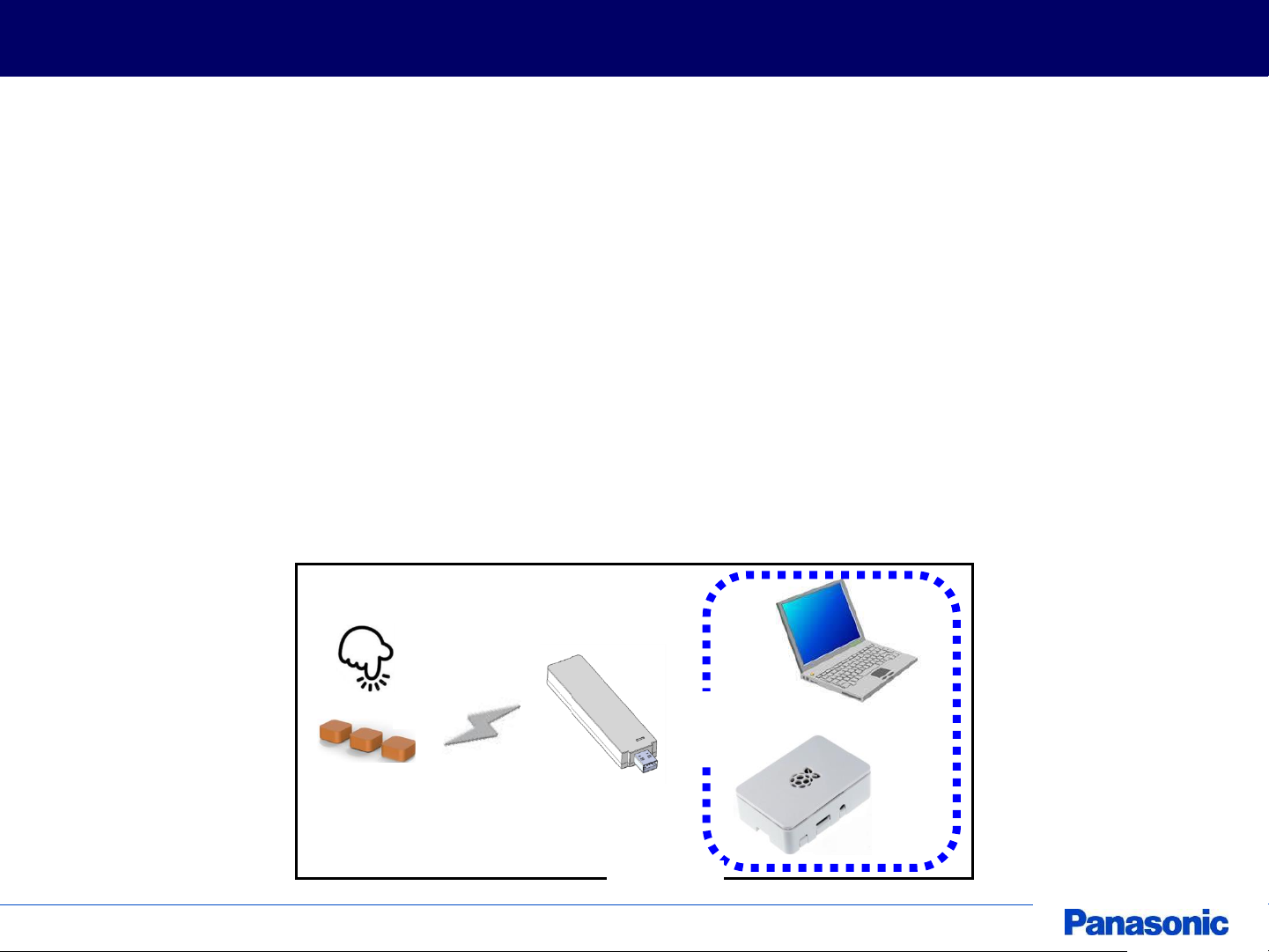
System Configuration
The configuration of “eny” system is shown in Figure 1.
Pressing the “eny button” generates electricity and become active for a while ( less than 5[ms] ).
During the active time the button can transmit and receive RF signal.
The “eny receiver” should be plugged into PC or other host computer via USB and recognized as Virtual
COM port (VCP).
The receiver can communicate with the “eny button” while the button is active.
The operation is done in ISM frequency (2.4GHz band) and the protocol is “eny” original.
“eny button” does not need the power supply, and “eny receiver” requires 5V via USB.
The ID of the connected “eny button” will be output on the terminal software (Putty, Teraterm etc.).
The application should be implemented in the host computer to be triggered by the signal from “eny
button”.
© Panasonic Corporation
eny button
2.4GHz
eny receiver
Figure 1
[2]
via
USB
PC
OR
RasberryPI
Page 4

Sequence Between Button And Receiver
The sequence between “eny button” and “eny receiver” is shown in Figure 2.
The button makes three sets of ID transmission at a maximum.
Each set contains two transmissions in different frequencies, Freq1 and Freq2.
This mechanism can improve the robustness of the communication.
There is no simultaneous radio frequency output of Freq1 and Freq2.
eny button eny receiver
Press button
Set 1
Set 2
Set 3
Send ID in Freq1 (seq=1)
Send ID in Freq2 (seq=2)
Return ACK signal
Send ID in Freq1 (seq=3)
Send ID in Freq2 (seq=4)
Return ACK signal
Send ID in Freq1 (seq=5)
Send ID in Freq2 (seq=6)
Return ACK signal
Figure 2
© Panasonic Corporation
[3]
Page 5

Communication I/F In Host Computer
pair view
Shows the content of the pair table.
-
[[Index]] : [ID]
[[Index]] : [ID]
...
where
Index : 0
ID : 8 digits, hexadecimal
pair add [ID]
Adds ID of the specified eny button to
the pair table.
ID : 8 digits, hexadecimal
[Result code] [Command code] ([Description])
where
Result code:
00 (Success)
02 (Too few arguments)
03 (Too many arguments)
05 (Parameter invalid)
07 (The pair table is full)
Command code: Internal code
ID will be r
unused index.
pair del [Index]
Deletes ID of the specified eny button
from the pair table.
Index : 0
pair reset
Clear all IDs in the pair table.
-
get_id
Shows the RX ID.
-
[RX_ID] (RX_ID(GET))
help Shows command list.
-
Command list
Command I/F between “eny receiver” and the host computer is shown in Figure 3.
The communication between “eny button” and “eny receiver” is established based on whitelist (*1).
Use “pair” command to handle the whitelist called “pair table”.
Command:
Command Description Parameter Response Note
- 31, decimal
- 31, decimal
egistered to the lowest
Note:
- Receiver outputs the button information in ASCII text via USB when it receives the signal successfully.
e.g. [Button ID] [Sequence No.] [Cumulated No.] [Channel No.]
*1 : A whitelist is a list or register of entities that are being provided a particular access. Entities on
© Panasonic Corporation
the list will be accepted, otherwise denied.
Figure 3
[4]
Page 6

Communication I/F In Host Computer
Serial port settings :
Speed :115200 [bps]
Data bits :8 [bits]
Stop bits :1 [bit]
Parity :None
Flow control :None
Setting example (PuTTY):
© Panasonic Corporation
Figure 4
[5]
Page 7

Communication I/F In Host Computer
Command execution examples :
© Panasonic Corporation
⇒
Help command
Figure 6
[6]
⇒
Pair table / ID information
Page 8

LED Status On “eny receiver”
LED status on “eny receiver” is shown in Figure 6.
1. Blue LED : Blinks when it receives ID information successfully
2. Green LED : Become ON when the power is supplied
3. Red LED : Become ON when the internal error detected
LED
OFF
LED
OFF
LED
Blink
- BLUE-
LED ON
-GREEN-
LED
eny receiver
© Panasonic Corporation
LED
OFF
LED ON
-RED-
Figure 6
[7]
Page 9

Disclaimer
Please note that the information or the program it in this document may be
changed or updated without notice. For any damages caused by these
changes and updates, we are not responsible.
© Panasonic Corporation
[8]
 Loading...