

Page 1

L Q
www.qprox.com
E1106
User Manual
The New Vision of TouchTM
Page 2

Contents
E1106 User Manual
1 E1106 Overview........................................................................................................................3
1.1 Introduction....................................................................................................................................................................................3
1.2 Contents of Kit...............................................................................................................................................................................3
2 Setting Up the E1106 ...............................................................................................................4
3 QT1106 Demo Software...........................................................................................................5
3.1 Introduction....................................................................................................................................................................................5
3.2 How to Use the E1106 QWheel/QSlide Assembly.........................................................................................................................6
3.3 QT1106 Demo Parameters............................................................................................................................................................6
3.4 Main Window.................................................................................................................................................................................6
3.5 Setup Dialog Box...........................................................................................................................................................................6
3.5.1 Wheel/Slider Area......................................................................................................................................................................................6
3.5.2 Keys Area...................................................................................................................................................................................................7
3.5.3 AKS Modes Area........................................................................................................................................................................................7
3.5.4 Operating Modes Area...............................................................................................................................................................................7
3.5.5 General Area..............................................................................................................................................................................................8
3.5.6 Low Power/Sync/Sleep Mode Area............................................................................................................................................................8
3.5.7 Other Options.............................................................................................................................................................................................8
4 E1106 Control Board Assembly Details.................................................................................9
4.1 Circuit Diagram..............................................................................................................................................................................9
4.2 E1106 Control Board Assembly Components.............................................................................................................................10
5 Troubleshooting.....................................................................................................................12
List of Figures
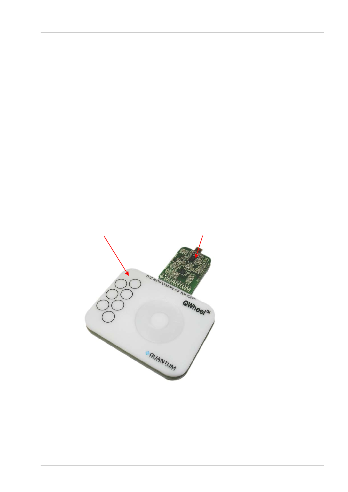
Figure 1: E1106 Evaluation Assemblies and Control Board............................................................................................................................................3
Figure 2: E1106 Connections...........................................................................................................................................................................................4
Figure 3: QT1106 Main Window.......................................................................................................................................................................................5
Figure 4: QT1106 Setup Dialog Box ................................................................................................................................................................................5
Figure 5: E1106 Circuit Diagram......................................................................................................................................................................................9
Figure 6: E1106 Control Board Assembly Details..........................................................................................................................................................10
Figure 7: QWheel Assembly Details Figure 8: QSlide Assembly Details..................................................................................................................10
List of Tables
Table 1: QT1106 IC, 32-QFN (U3).................................................................................................................................................................................11
2 of 14
Page 3
1 E1106 Overview
1.1 Introduction
This kit is designed for the evaluation and development of applications using the QT1106 IC. The
kit includes evaluation assemblies (E1106 – see Figure 1), cables and QT1106 Demo software.
Each E1106 assembly has a serial (USB) interface allowing connection to a computer fo r control
and data viewing via QT1106 Demo computer software.
This unique IC allows designers to create speed or volume controls, using a wheel/slide r and keys
as the interface on the panel of an appliance or personal electronic device.
Refer also to the QT1106 datasheet.
1.2 Contents of Kit
1 x E1106 control board
1 x E1106 QWheel assembly
1 x E1106 QSlide assembly
1 x USB-computer cable
2 x sample QT1106 ICs
E1106 User Manual
1 x CD-ROM containing information about the QT1106, including QT1106 Demo softwa re
(revision 7.2 or later) and documentation
E1106 QWheel
Assembly
E1106 Control Board
Figure 1: E1106 Evaluation Assemblies and Control Board
3 of 14
Page 4
2 Setting Up the E1106
r
A
To prepare the E1106 for use, proceed as follows:
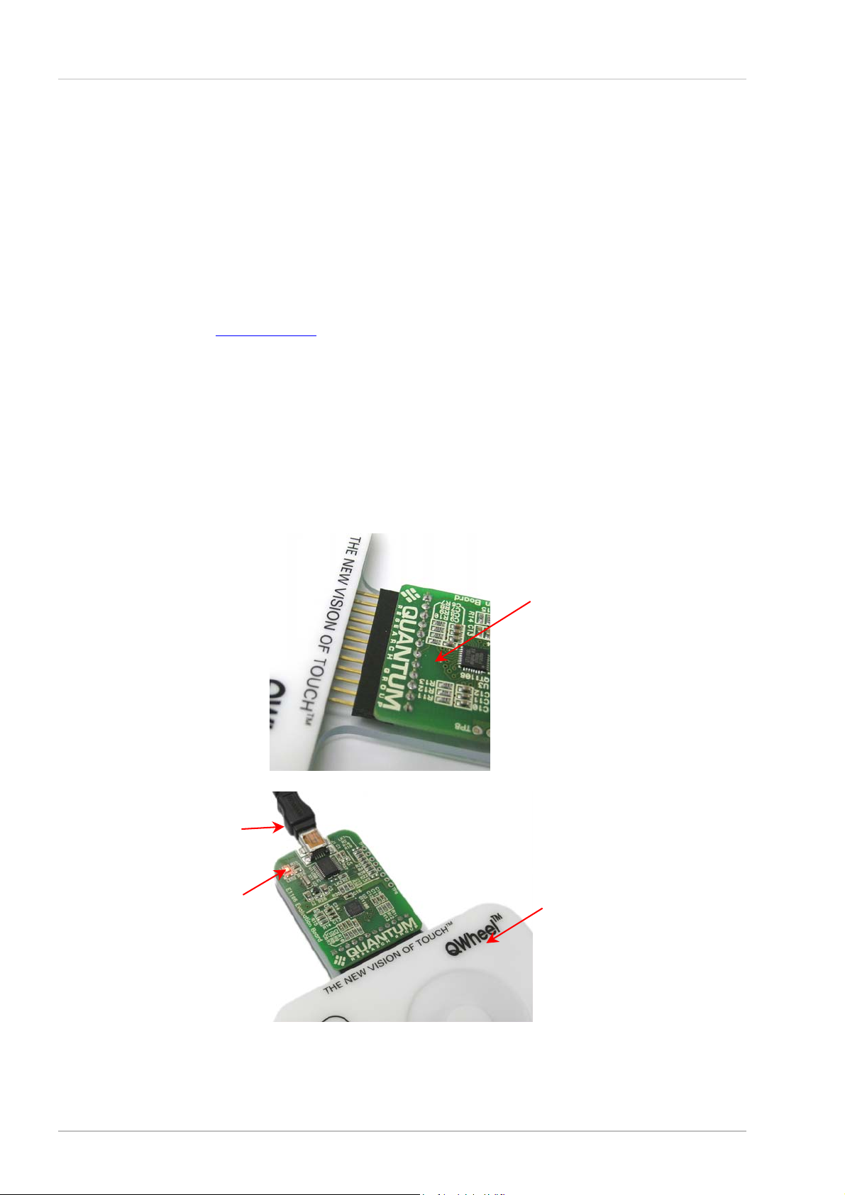
1. Connect the E1106 control board to the QWheel or QSlide evaluation assembly, ensuring
correct orientation of the connector (see Figure 2).
2. Using the USB cable provided, connect the E1106 control board to the computer (see
Figure 2). The LED on the E1106 is lit constantly to indicate that there is power to the board.
3. Install the QT1106 Demo software; either method is acceptable:
a. Put the supplied CD in the CD drive of the computer. Copy the contents of the CD to the
computer. Double-click the QT1106 Demo software to open it.
OR
E1106 User Manual
b. Go to www.qprox.com
, point to the Support tab and click Download Archive. Click
Software and then the QT1106 Demo link. A dialog box appears asking if you want to run
or save the file that you are about to download. Click Run. This automatically downloads
the software.
If a dialog box appears saying “The publisher could not be verified. Are you sure you want
to run this software?” click Run.
4. QT1106 Demo software is displayed on the computer monitor (see Figure 3, page 5).
Note: the E1106 QWheel and QSlide assemblies are supplied with a grounded transp arent
backplate that allows the assemblies to be operated while being handheld, without requiring
recalibration. The backplate can be removed if required.
Control board
should be
component
side up.
Connecting the E1106 Control Board to the E1106 QWheel or QSlide
USB cable to compute
LED
Connections between the E1106 Control Board and computer
Figure 2: E1106 Connections
4 of 14
QWheel
ssembly
Page 5
E1106 User Manual
r
r
y
(
)
r
A
3 QT1106 Demo Software
3.1 Introduction
QT1106 Demo software is used with the E1106 evaluation assembly. With QT1106 Demo software
you can send commands and see the effect that changing pa rameters has (see Section 3.2
onwards).
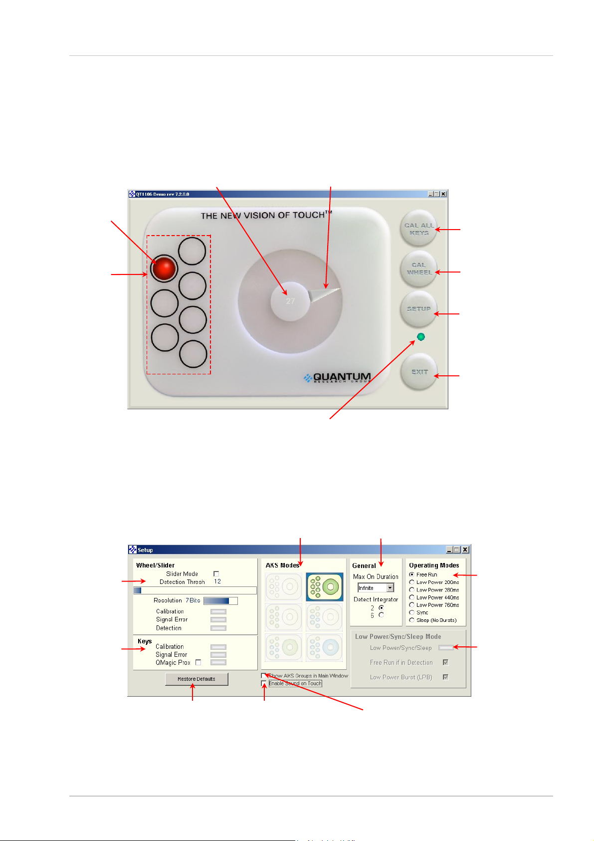
Numerical Indicator
Shows the numerical equivalent
of the last reported touch position
(see Page 6)
Wheel/Slider Indicator
Shows the last reported
touch position
see Page6
Key 6 is shown
being touched.
Keys Indicators:
Shows which key is
being touched and
also allows each
key to be calibrated
individuall
(see Page 6)
Figure 3: QT1106 Main Window
Connection indicator (green) is constant when
Connection:
the E1106 is connected to the computer,
flickering when it is not (see Page 6)
Cal All Keys:
Calibrates all the keys
simultaneously
(see Page 6)
Cal Wheel/Slider:
Calibrates the
wheel/slide
(see Page 6)
Setup:
ccesses the Setup
parameters
(see Page 6)
Exit:
Closes the QT1106
Demo software
(see Page 6)
Wheel/Slider:
Slider Mode
Detection Thresh
Resolution
Calibration
Signal Erro
Detection
(see Page 6)
Keys:
Calibration
Signal Erro
QMagic Prox
(see Page 7)
Restore Defaults:
Restores the default
parameters
(see Page 8)
when wheel/slider or keys
Figure 4: QT1106 Setup Dialog Box
AKS Modes:
(see Page 7)
Enable/disable sound
are touched
(see Page 8)
General:
Max On Duration Detect Integrator
(see Page 7)
Operating
Modes:
(see Page 7)
Low Power/Sync
/Sleep Mode:
Enables parameters for
these modes
(see Page 8)
Enable/disable to show the
AKS groups in the main
window
(see Page 8)
5 of 14
Page 6

E1106 User Manual
3.2 How to Use the E1106 QWheel/QSlide Assembly
1. Place the E1106 QWheel/QSlide on a level surface.
2. Keeping clear of the E1106, click Cal All Keys or Cal Wheel/Slider (as applicable) on the
QT1106 Demo software. Do this every time the E1106 is unplugged from the computer.
However, if the grounded transparent backplate has been removed from the E1106 then the
E1106 must also be recalibrated each time it is moved.
3. Depending upon whether the QWheel or QSlide is connected, move your finger about the
wheel/slider area of the E1106. As you do so the Wheel Indicator shows the last reported
touch position (see Figure 3, page 5) and the Numerical Indicator shows the numerical
equivalent (see Figure 3, page 5). When you remove your finger, the last position touched will
be locked on the display.
4. If the QT1106 Demo software is not detecting, or detection is sporadic, decrease the detection
threshold slightly (Detection Thresh).
5. Refer to Section 3.3, Page 6 onwards, for details of which parameters you can change.
3.3 QT1106 Demo Parameters
(refer to the QT1106 datasheet for more information)
The QT1106 Demo software comprises a main window and a setup dialog box. The different
parameter areas simulate the effect that changing options has on the device’s performance. Any
option which is not available appears dimmed. Refer to Figure 3 and Figure 4, Page 5 to see a
depiction of the QT1106 Demo software.
3.4 Main Window
The Wheel/Slider Indicator shows the position of touch on the E1106 and its numerical equivalent
is shown on the Numerical Indicator (from 0 to 255, depending on the resolution – see
Section 3.5.1). This changes in real time as the position of touch on the E1106 changes.
The Keys Indicators show when a key is being touched; the key turns red for the duration of the
touch.
Calibrate each key individually by clicking that particular key or calibrate them altogether by clicking
Cal All Keys.
Calibrate the wheel/slider by clicking Cal Wheel/Cal Slider.
Access the setup parameters by clicking Setup.
The connection indicator (green) is constant when the E1106 is connected to the computer,
flickering when it is not.
Click Exit to close the QT1106 Demo software.
3.5 Setup Dialog Box
3.5.1 Wheel/Slider Area
Slider Mode – the default setting for the software is the wheel. Select the check box to change the
setting to the slider. A slider representation will be shown in the main window.
Detection Thresh - sets the amount of signal change which will cause the E1106 to register touch
detection. The values are 0…255, default = 12. Move the cursor over the Detection Thresh bar
until the cursor turns into a double-headed arrow. Holding the left mouse button down, move the
slider left or right to select a new threshold. The actual value is shown above the bar and changes
in real time as the slider moves.
6 of 14
Page 7

Resolution – sets the resolution of the wheel/slider; default = 7 bits. Move the cursor over the
Resolution bar until the cursor turns into a double-headed arrow. Holding the left mouse button
down, move the slider left or right to select a new resolution. The number of bits is shown at the
side of the bar and changes in real time as the slider moves.
2 Bits: 4 positions (0...3)
3 Bits: 8 positions (0...7)
4 Bits: 16 positions (0...15)
5 Bits: 32 positions (0...31)
6 Bits: 64 positions (0...63)
7 Bits: 128 positions (0...127) (default)
8 Bits: 256 positions (0...255)
Calibration – this indicator lights to show when wheel/slider calibration is occurring.
Signal Error – this indicator lights to show that the signal has the wrong polarity, usually due to
E1106 assembly movement (when the transparent backplate is not fitted). Clicking Cal Wheel/Cal
Slider will resolve the error.
Detection – this indicator lights when a touch is detected on the wheel/slider.
3.5.2 Keys Area
Calibration – this indicator lights to show when key calibration is occurring.
Signal Error – this indicator lights to show that the signal has the wrong polarity, usually due to
E1106 assembly movement (when the transparent backplate is not fitted). Clicking Cal All Keys
will resolve the error.
E1106 User Manual
QMagic Prox – this enables proximity mode on key 7 (when the check box is selected), allowing
the product to auto power up or activate its display with hand approach.
Note: once activated it can only be deactivated by clearing the check box and resetting the chip.
This has to be done by physically unplugging the device. Clearing the check box is not enough.
3.5.3 AKS Modes Area
AKS Modes – Adjacent Key Suppression - this patented feature works to prevent multiple keys
from responding to a single touch. It suppresses touch from weaker responding keys and only
allows a dominant key (or group of keys) to detect. Click an AKS Modes icon to select a new AKS
mode. In the main window the keys and wheel/slider backgrounds change color to indicate the
grouping of the new mode (if the Show AKS Groups in Main Window check box is selected).
AKS disabled (no AKS)
AKS global (default) (all keys AKS’d together)
AKS K + W
AKS 4K
AKS 4K
AKS 1K + (6K
1
2
+ 3K3 + W1
2
+ (3K3 + W1)
4
+ W1)
3.5.4 Operating Modes Area
Operating Modes – select one of the Operating Modes options. If any option, apart from Free
Run (default), is selected then the corresponding options in the Low Power/Sync/Sleep Mode
area become available. The unavailable options appear dimmed.
1
Wheel or Slider.
2
keys 1-4 AKS’d together.
3
keys 5-7 AKS’d together.
4
keys 1-6 AKS’d together.
7 of 14
Page 8

E1106 User Manual
3.5.5 General Area
Max On Duration – the device can time out and recalibrate each key independently after a
continuous touch detection that lasts for the chosen ‘Maximum on-duration’ (MOD). This en sures
that a key can never become ‘stuck on’ due to foreign objects or other external influences. After
recalibration the key will continue to function normally. The nominal delay is selectable to be 10s,
20s, 60s, or infinite (default), though the actual delay may vary in some operating modes (see the
QT1106 datasheet for more information).
Detect Integrator – Detect Integrator (DI) filter confirmation reduces the effects of noise on key
states. The DI mechanism requires a specified number of measurements that qualify as detections
(and these must occur in a row) or the detection will not be reported. In a similar manner, the end
of a touch (loss of signal) also has to be confirmed over several measurements. The QT1106
provides a choice of either two or six DI measurements for confirming start of touch; end of touch
always uses two measurements. Select the appropriate check box.
3.5.6 Low Power/Sync/Sleep Mode Area
Low Power/Sync/Sleep – this indicator is lit when the QT1106 IC is in a Low Power/Sync/Sleep
mode. Although a Low Power/Sync/Sleep mode may be selected in the Operating Modes area,
when a key or the wheel/slider is touched the indicator goes out. This is because for the period of
detection/touch the mode automatically changes to Free Run and then back to the original mode
when detection/touch is finished.
Free Run if in Detection – select the Free Run if in Detection check box to automatically change
the mode to Free Run whenever a touch is selected. This makes the response quicker, otherwise
the device goes back to sleep for the allotted time between measurements.
Low Power Burst (LPB) – select the LPB check box to initiate a burst after each SPI transfer or
/SS Wake pulse, clear the check box to stop the LP bursts.
3.5.7 Other Options
Restore Defaults – click this button to restore the default settings.
Show AKS Groups in Main Window – select this check box to show the selected AKS group with
the keys and wheel/slider colored to show the grouping in the main window.
Enable Sound on Touch – select this check box to enable a sound to be heard when a key or the
wheel/slider is touched.
8 of 14
Page 9

E1106 User Manual
4 E1106 Control Board Assembly Details
4.1 Circuit Diagram
QT1106
Figure 5: E1106 Circuit Diagram
9 of 14
Page 10

E1106 User Manual
4.2 E1106 Control Board Assembly Components
LED
U3, QT1106 IC
J2, connection to
QSlide/QWheel
Figure 6: E1106 Control Board Assembly D etails
Figure 7: QWheel Assembly Details Figure 8: QSlide Assembly Details
Wheel element
Slider element
10 of 14
Page 11

E1106 User Manual
QT1106 (32-QFN) IC
Table 1: QT1106 IC, 32-QFN (U3)
Pin Name Pin Name
1 SPREAD 17 SNSB1
2 /RST 18 SNSB
3 Vdd 19 SNSB
4 OSC 20 SNSB
5 n/c 21 DRDY
6 CHANGE 22 Vss
7 SNSB7 23 SCLK
8 SNSB6 24 /SS
9 SNSB5 25 MOSI
10 SNSB 26 MISO
11 SNSB 27 SNSA
12 SNSB 28 SNSA
13 SNSB 29 SNSA
14 SNSB4 30 SNSA1
15 SNSB3 31 SNSA2
16 SNSB2 32 SNSA3
Power Supply
The QT1106 power supply should be locally regulated using a three-terminal device, to between
2.8V and 5.0V.
Wheel Element
The wheel element is resistorless and consists of etched copper electrodes.
Slider Element
The slider element is resistorless and consists of etched copper electrodes.
Sampling Capacitors
C5…C14 are the Cs sampling capacitors. Increasing their value will increase sensitivity and
resolution of measurement, but will also tend to make the response time slower.
LED
The LED will switch off momentarily when keys/wheel/slider are touched, and also when touch is
removed. When the touch moves around the wheel/slider the LED will flicker on and off for the
duration of the movement of the touch.
11 of 14
Page 12

5 Troubleshooting
Problem Potential Cause and Solution
E1106 User Manual
Software will not
communicate with the
computer
Software appears locked ` Incorrect detection threshold
Noisy or erratic signal ` Noisy power supply
` Bad SPI or USB connection
Check that the USB cables are connected properly
Check/replace cables
Ensure that the E1106 assembly is getting power and the LED is on
1
below
` See
Change the detection threshold to a lower setting
Try a different USB port or computer
` Cables or E1106 assembly too close to strong noise source1
(such as a power line or switching noise source)
Increase the distance between the E1106 assembly and the noise
source
Ensure that the grounded transparent backplate is in place on the
E1106 assembly
` E1106 assembly is not mechanically stable
Prevent E1106 assembly from moving around if the backplate is not
fitted
` Strong RFI from a transmitter or adjacent digital product
Remove the noise source or shield against it
` USB cable connected via a USB hub
Connect the USB cable directly to the computer
QMagic Prox feature will
not turn off
` Once activated it can only be deactivated by resetting the chip. This has
to be done by physically unplugging the device.
12 of 14
Page 13

NOTES:
E1106 User Manual
13 of 14
Page 14

L Q
www.qprox.com
Corporate Headquarters
1 Mitchell Point
Ensign Way, Hamble
Southampton SO31 4RF
United Kingdom
Tel +44 (0)23 8056 5600
Fax +44 (0)23 8045 3939
Copyright © 2006-2007 QRG Ltd
All rights reserved
Patented and patents pending
Development Team
Lim Wei Jiun, Martin Simmons, Alan
Bowens, Luben Hristov
North America
651 Holiday Drive Bldg. 5 / 300
Pittsburgh, PA 15220
USA
Tel 412-391-7367
Fax 412-291-1015
REV 204.0707
 Loading...