

Page 1
Dynamic Dolphin
Remote
Basic Operation Instructions
Page 2

2 Basic Operation Instructions Dolphin
IMPORTANT NOTICE
This manual describes basic operation for the Dynamic Dolphin Remote
only and must be read in conjunction with the owners manual supplied with
your power chair. Please read both manuals in their entirety before operating
the Dynamic Dolphin Remote or your power chair.
This manual is intended as a supplement to the in-service training provided
by your authorized provider. If you have any questions or problems regarding
the Dynamic Dolphin Remote, please contact your authorized provider.
Copyright © 2001
Pride Mobility Products Corporation
Page 3

Dolphin Basic Operation Instructions 3
TABLE OF CONTENTS
INTRODUCTION ................................................................................ 4
Dynamic Dolphin Remote ......................................................................... 4
MAGNETIC KEY LOCK SYSTEM ............................................... 6
JOYSTICK OONAPU ........................................................................ 6
DRIVE PROGRAM SELECTION................................................... 6
ACTUATOR CONTROL .................................................................... 7
Page 4

4 Basic Operation Instructions Dolphin
INTRODUCTION
Welcome to Quantum Rehab, a division of Pride Mobility Products
Corporation (Pride). Quantum Rehab is dedicated to the customization of
power chairs for users with advanced rehabilitation and mobility issues.
Quantum Rehab also expands possibilities for enhanced healthcare attendant
control over power chair functions to provide a secondary level of support
for our customers where necessary.
Dynamic Dolphin Remote
The Dynamic Dolphin Remote is a DX compatible control unit complete
with a joystick, fully functional keypad, and the capability to support up to
five different drive programs and several actuator functions.
This manual is designed to explain basic operation for the following functions
available with the Dolphin Remote:
1. Magnetic Key Lock System
- The user can lock the power chair to prevent unintended use of the
chair.
2. Joystick OONAPU
- OONAPU stands for Out Of Neutral At Power Up. This is a safety
measure designed to prevent unintended movement of the power chair.
3. Drive Program Selection
- The user can choose from one of five programs to control the movement
and speed of the power chair.
4. Actuator Control
- The user can control up to five actuators using the Dolphin Remote.
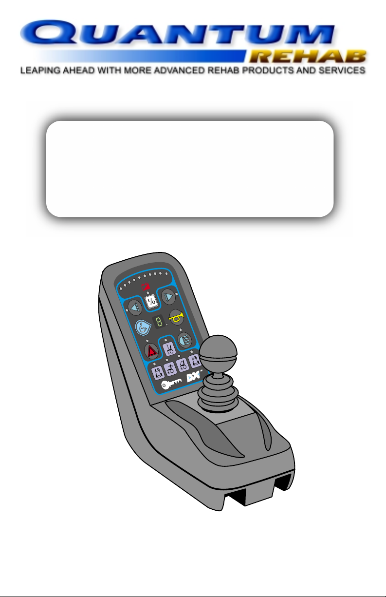
Figure 1 provides information on the Dynamic Dolphin Remote components
and connections. Use this diagram to familiarize yourself with the function
and location of each component before using the Dynamic Dolphin Remote.
Page 5

Dolphin Basic Operation Instructions 5
Status LED
Indicates On/Off Status, and
flashes to indicate system faults.
On/Off Switch
Toggles the system on or off.
Drive Program Display
A 7-segment display shows the
currently selected drive program.
Remote Status LED
Indicates status of Dolphin Remote.
Drive Program Select Switch
This switch will scan through and
select one of five drive programs.
Hazard Light Switch & LED
Press to make both indicators flash
simultaneously. Press again to turn off.
LED flashes when activated.
Left & Right
Battery Gauge
A series of ten LEDs, which
indicate charge level
Magnetic Key Lock & LED
Locks DX System to prevent unauthorized use. Upon reactivation of
unit, LED will flash until magnetic key is used to unlock system.
Indicator Switches & LEDs
Press the appropriate switch to activate
turn indicator. Press again to turn off.
LED flashes when activated.
Horn Switch
Press to activate warning horn.
Light Switch & LED
Toggles the head/tail/side lights on or
off. LED is lit when activated.
seat height leg rest adjust
Actuator Select Switches
5 switches for actuator selection. Not used for
actuator operation, only selection. LED above
switch lights up when activated.
(right & left)
Joystick
Controls the speed and direction of
power chair, as well as actuator
control when selected.
seat tiltback tilt
Magnetic Key
Used to lock and unlock
the DX System.
Battery Connection Socket
Connects to Battery Charger Plug.
DXBUS Sockets
Enables DXBUS cable to be used
to interconnect to the remainder of
the DX System.
Figure 1. Dolphin Components and Connections
BA CK VIEW
Page 6

6 Basic Operation Instructions Dolphin
MAGNETIC KEY LOCK SYSTEM
1. To arm the locking system, hold the magnetic key on or near the key
symbol on the Dolphin front panel. See figure 1. The system will beep
and automatically power itself down. No LEDs should be lit.
2. To turn the power chair back on, press the On/Off Switch. The system
will power on, but the locking system needs to be disarmed before normal
operation can occur. The key symbol will flash, indicating that the system
should be disarmed.
3. To disarm the lock, put the magnetic key on or near the key symbol. The
LED will stop flashing, and normal operation may resume. If the locking
system is not disarmed within one minute, the Dolphin will shut itself
off.
JOYSTICK OONAPU
If the power chair is powered up while the joystick is not in the neutral
position, the System Status LED will flash for as long as the condition persists
up to a maximum of five seconds. After five seconds, a Fault Flash Code is
signaled on the System Status LED, and the Remote Status LED will flash.
To clear the fault, power down, put the joystick in neutral, and power the
system back on.
DRIVE PROGRAM SELECTION
The Dolphin can control up to five drive programs. Drive Program 1 is
configured as the slowest, and Drive Program 5 is configured as the fastest.
To select the preferred drive program, press the Drive Program Select Switch.
The selected drive program will be displayed on the 7-segment display. See
figure 1. Each press of the Drive Program Select Switch will increase the
drive program to the next level until it cycles back to Drive Program 1.
Page 7

Dolphin Basic Operation Instructions 7
ACTUATOR CONTROL
The Dolphin can support the control of up to five actuators if a correctly
configured actuator control module is present.
NOTE: Once an actuator is selected, driving will be inhibited until the
actuator is deselected.
1. Press the Actuator Switch representing the seat function needing
adjustment. See figure 2.
2. Push the joystick full forward or full reverse to adjust the actuator. A
forward command with the joystick will extend the actuator; a reverse
command will retract the actuator.
NOTE: When using the Dolphin in conjunction with a TRx Seating System,
give a reverse command to extend the actuator, release the joystick, then
give another reverse command to retract the actuator. The reverse command
toggles between extend and retract only for TRx units.
3. Press the Actuator Switch again to deselect the actuator and resume normal
operation.
Figure 2. Actuator Control Selection
Page 8

8 Basic Operation Instructions Dolphin
INFMANU1756/A/MAY 2001
Exeter, PA
Quantum Hotline: 1-866-800-2002
Visit the Rehab Zone at:
www.quantumrehab.com
 Loading...