

Page 1

Quantum DX-Series
System Unpacking
and Installation Instructions
Introduction 3
Selecting an Installation Location 4
Rack Space Requirements.........................................................................................5
Environmental Conditions .......................................................................................6
Preparing for the Installation 7
Providing Necessary Tools and Equipment ..........................................................7
Taking ESD Precautions ...........................................................................................7
Unpacking the DX-Series System 7
Installing the DX-Series System 12
Locating the Mounting Position ............................................................................12
Installing the DX-Series Storage Array.................................................................15
Installing the Fibre Channel Switch (DX100 Only).............................................20
Installing the Ethernet Switch (DX100 Only).......................................................25
Installing the DX-Series Controller .......................................................................27
Installing the AC Power Sequencers (DX100 Only) ...........................................30
Installing Additional Storage Arrays 41
Cabling the DX-Series System 41
Installing the SFP Connectors ................................................................................41
Verifying Storage Array Dip Switches .................................................................43
Cabling a DX30.........................................................................................................44
Cabling a DX100.......................................................................................................46
Document 6513502-06 A01, October 2006 1
Page 2

Quantum DX-Series Series Unpacking and Installation Instructions
Document 6513502-06 A01
October 2006
Power Cabling..........................................................................................................54
Configuring the DX-Series System 54
Turning On the DX-Series System.........................................................................55
Initially Configuring the DX-Series System.........................................................57
Accessing the DX-Series Controller ......................................................................64
Adding a Partition ...................................................................................................68
Configuring the Network Information.................................................................70
Configuring the Date and Time.............................................................................71
Configuring the Security Options .........................................................................72
Configuring the Fibre Channel Settings...............................................................75
Configuring the Email Settings..............................................................................78
Configuring the SNMP Settings ............................................................................80
Enabling Fibre Channel Compression..................................................................84
Saving the DX-Series Configuration File..............................................................85
Restarting the System..............................................................................................86
Made in the USA.
Quantum Corporation provides this publication “as is” without warranty of any kind, either express or implied, including but not limited to
the implied warranties of merchantability or fitness for a particular purpose. Quantum Corporation may revise this publication from time to
time without notice.
COPYRIGHT STATEMENT
© Copyright 2006 by Quantum Corporation. All rights reserved.
Your right to copy this document is limited by copyright law. Making copies or adaptations without prior written authorization of Quantum
Corporation is prohibited by law and constitutes a punishable violation of the law.
TRADEMARK STATEMENT
Capacity on Demand (CoD), Crosslink Mechanism, DLT, DLTSage, DLTtape, Super DLTtape, Performance on Demand, (PoD), PRISM,
PRISM Storage Architecture logo, SiteCare, StackLink, StorageCare, SuperLoader, and ValueLoader are all trademarks of Quantum
Corporation. Quantum, the Quantum logo, and the DLTtape logo are all registered trademarks of Quantum Corporation.
Other trademarks may be mentioned herein which belong to other companies.
2
Page 3

Quantum DX-Series System Unpacking and Installation Instructions
Document 6513502-06 A01
October 2006
Introduction 0
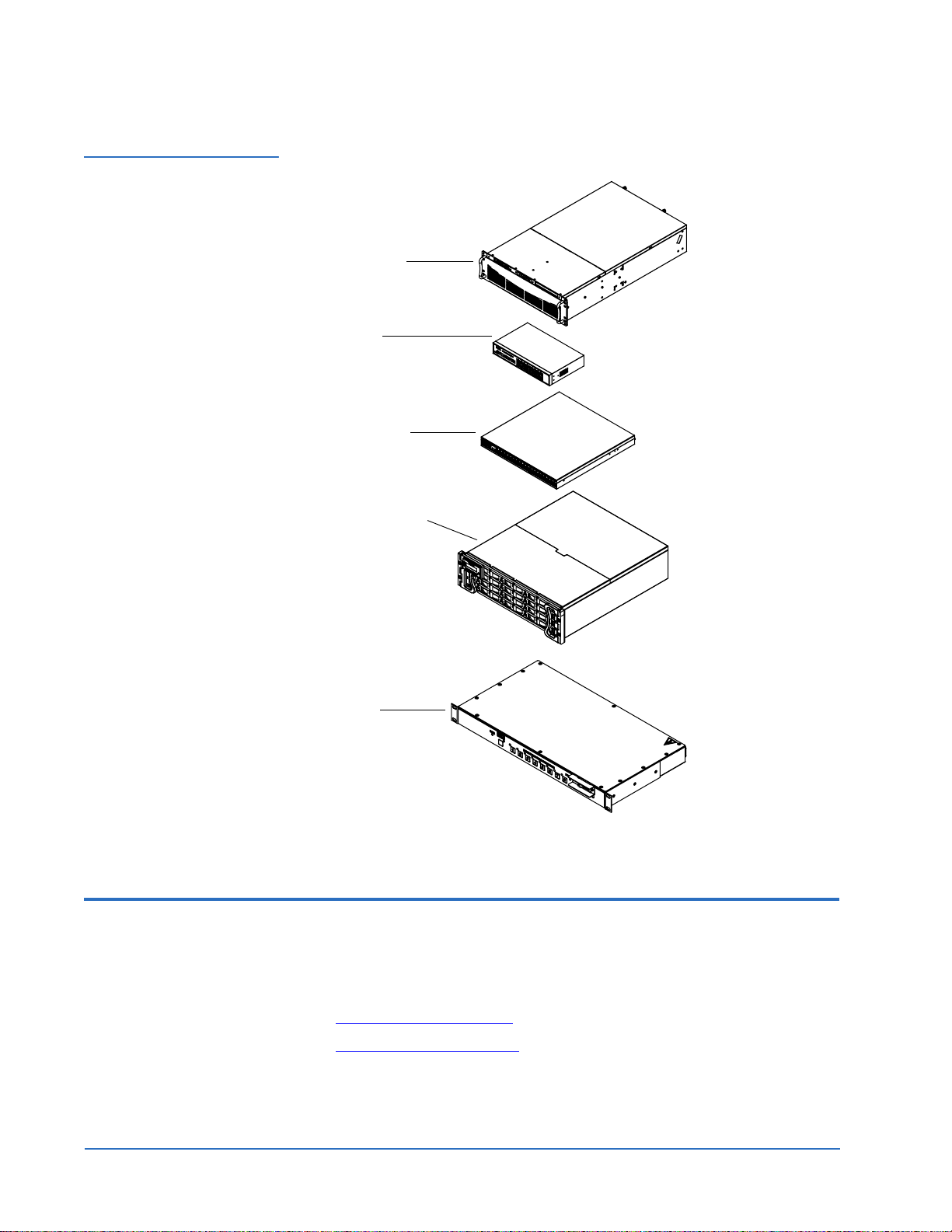
The Quantum DX-Series system consists of the DX30 and DX100 device. Both
are backup devices based upon high speed disk drives instead of tape drives.
The DX30 consists of:
• A single controller and 1 to 4 storage arrays.
The DX100 consists of:
• A single controller and 2 to 16 storage arrays
• One or two Fibre Channel switches
• An Ethernet switch
• Two or more AC power sequencers.
The system emulates an ATL P1000 library with up to 55 virtual digital linear
tape (DLT™) 7000 tape drives for DX100 and up to 30 DLT7000 tape drives
for DX30 (see figure 1
).
Note: The DX-Series storage array is shipped with the following RAID
configuration (refer to the Quantum DX-Series User’s Guide
PN6513501 for more information on RAID configurations):
• 1 logical drive configured in RAID 5 (7 data drives + 1 parity
drive)
• 1 logical drive configured in RAID 5 (6 data drives + 1 parity
drive)
• 1 global hot spare
To reconfigure the DX-Series storage array to either remove the hot
spare or add an additional hot spare (total of two hot spares), refer
to the Quantum DX-Series Field Service Manual PN6513503.
RAID configuration MUST be set prior to powering on the DX-Series
system.
Both the DX30 and the DX100 use the same system components (controller
and storage arrays). The DX100 storage arrays, however, contain dual RAID
controllers and the overall DX100 system can expand to sixteen storage
arrays. The DX100 controller also has a full compliment of Fibre Channel
HBAs (two quad port HBAs and four dual port HBAs) whereas the DX30 has
two Fibre Channel HBAs (one quad port HBA and one dual port HBA).
This document describes how to unpack and install both a DX30 and DX100
system into a customer-provided rack enclosure.
The
Introduction 3
Page 4
Quantum DX-Series System Unpacking and Installation Instructions
Document 6513502-06 A01
October 2006
Figure 1 DX-Series
Components
DX-Series controller
Ethernet switch
(DX100 only)
Fibre Channel switch
(DX100 only)
DX-Series storage array
AC power sequencer
(DX100 only)
Selecting an Installation Location 0
When choosing an installation site for the DX-Series system, consider the
following requirements:
• Rack Space Requirements
• Environmental Conditions
4 Selecting an Installation Location
Page 5

Quantum DX-Series System Unpacking and Installation Instructions
Document 6513502-06 A01
October 2006
Rack Space Requirements
Figure 2 shows the minimum rack space required by both the DX30 and
0
DX100.
• Depth - 30 in (76.2 cm)
• Width - 19 in (48.3 cm)
• Height - 10.5 in (27 cm) - 3U per additional array
• DX30 base unit - 6U (15U with a maximum of 4 storage arrays)
• DX100 base unit - 12U (58U for a maximum of 16 storage arrays, two
Fibre Channel switches, two or more AC power sequencers, and one
Ethernet switch)
• Weight - Storage array - 75 lbs (34 kg), controller - 52 lbs (24 kg)
• DX100 only - Fibre Channel switch 20 lbs (9 kg), Ethernet switch -
5 lbs (2.3 kg), and AC power sequencer - 10 lbs (4.5 kg)
• Clearance behind DX-Series system - 4 in (10 cm) for proper air flow
• Clearance above DX-Series controller module - 6 in (15 cm) for access to
the fan modules and Fibre Channel HBAs in the controller.
Selecting an Installation Location 5
Page 6
Quantum DX-Series System Unpacking and Installation Instructions
Document 6513502-06 A01
October 2006
Figure 2 Rack Space
Requirements
1
9
i
n
(
4
8
.
3
c
m
3
)
)
m
c
1
9
o
t
2
.
6
7
(
n
i
6
3
o
t
0
Environmental Conditions
0
The installation site must have the following environmental conditions:
• Humidity: 20%-80% non-condensing
• Temperature: 15°C-35°C (59°F-95°F)
• Altitude: -984 to 10,000 feet (-300 to 3048 meters)
These environmental conditions apply when the DX-Series system is in
operation.
Note: For additional DX-Series specifications (including environmental
requirements during shipping and storage), see the Quantum
DX-Series User’s Guide (PN 6513501).
6 Selecting an Installation Location
Page 7

Quantum DX-Series System Unpacking and Installation Instructions
Document 6513502-06 A01
October 2006
Preparing for the Installation 0
Before you begin the installation procedure in this section, make the
following preparations as described in this section:
• Providing Necessary Tools and Equipment
• Taking ESD Precautions
Providing Necessary T ools and Equipment
Taking ESD Precautions
Provide the following tools for unpacking the DX-Series system:
0
0
• #1 PHILLIPS® screwdriver
• #2 PHILLIPS screwdriver
• #1 Flat head screwdriver
• Antistatic wrist strap included in accessory kit
Some components within the DX-Series system contain static-sensitive parts.
To avoid damaging these parts while performing installation procedures,
always observe the following precautions:
• Keep the DX-Series system turned off during all installation procedures.
• Use an antistatic wrist strap (included in the accessory kit).
• Keep static-sensitive parts in their original shipping containers until
ready for installation.
• Do not place static-sensitive parts on a metal surface. Place them inside
their protective shipping bag or on an antistatic mat.
• Avoid touching connectors and other components.
Note: Dry climates and cold-weather heating environments have lower
relative humidity and are more likely to produce static electricity.
Unpacking the DX-Series System 0
This section explains how to unpack the DX-Series system components and
move them to their final installation location. The DX-Series system is
shipped in two configurations: DX30 and DX100 (see table 1
Preparing for the Installation 7
):
Page 8

Quantum DX-Series System Unpacking and Installation Instructions
Document 6513502-06 A01
October 2006
Table 1 DX-Series
Packaging Contents
Components DX30 Base System DX100 Base System
Controller 1 1
Storage array* 1-single RAID
controller (4 max)
2-dual RAID
controllers (16 max)
Fibre Channel Switch Not required 1
Ethernet switch Not required 1
AC power kit
containing 2 AC power
sequencers
Not required 1 kit for every 4
storage arrays
(ordered separately)
* Additional storage arrays can be added to increase system capacity
By following these instructions, you help ensure that the system will continue
to be safeguarded after it arrives at the installation site.
Unpack and remove the following components from the packing materials
(see figure 3
, figure 4, figure 5, and figure 6):
• DX-Series controller
• DX-Series storage array(s)
• DX-Series Fibre Channel switch (DX100 only)
• Ethernet switch (DX100 only)
• AC power sequencer (DX100 only)
8 Unpacking the DX-Series System
Page 9
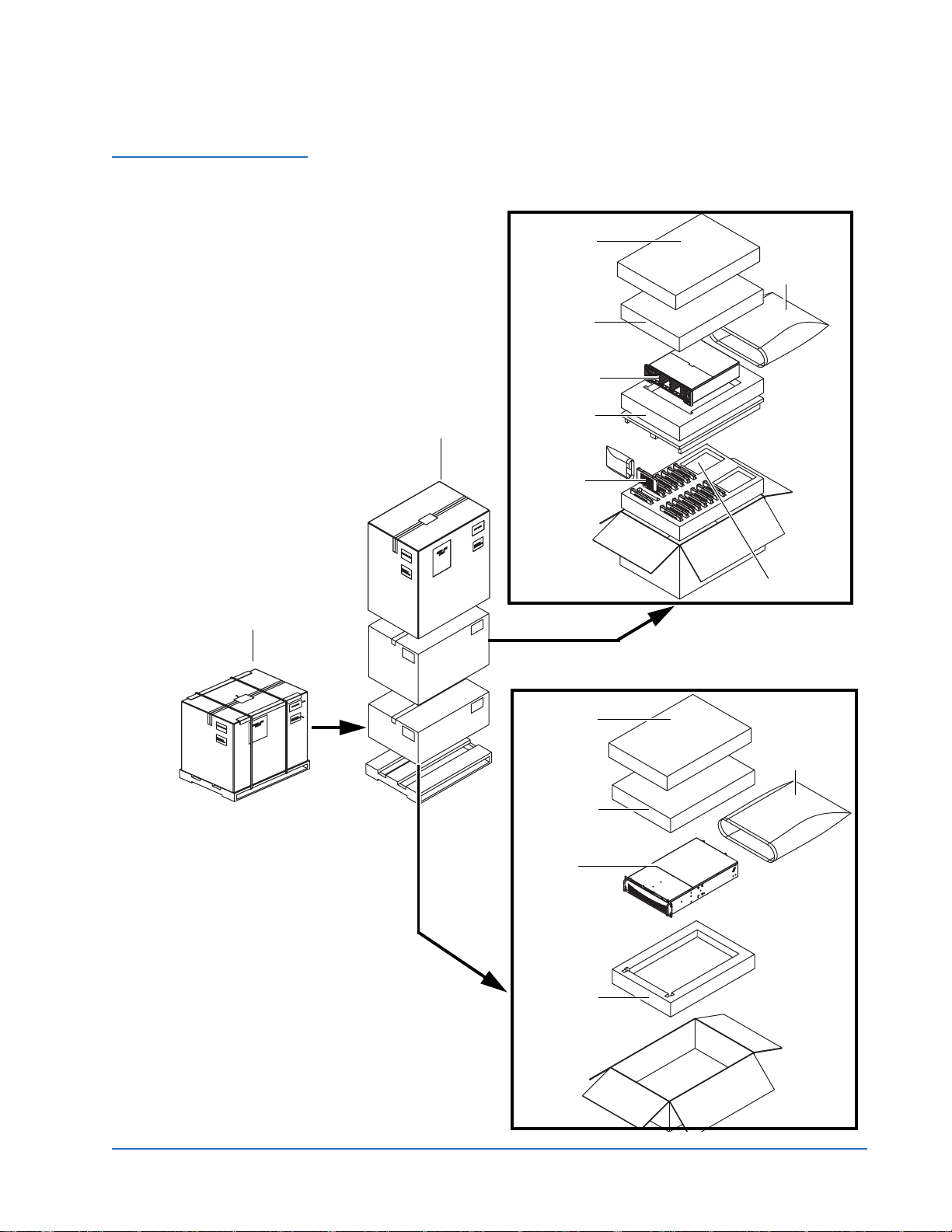
Figure 3 Unpacking the
DX30
Quantum DX-Series System Unpacking and Installation Instructions
Document 6513502-06 A01
October 2006
Storage array
accessory kit
Antistatic
bag
Top
packing foam
Storage array
Bottom
packing foam
Cover
Hard drive
sleds
DX30 packaging
RAID controller
Controller
accessory kit
Antistatic
bag
Top
packing foam
Controller
Bottom
packing foam
Unpacking the DX-Series System 9
Page 10
Quantum DX-Series System Unpacking and Installation Instructions
Document 6513502-06 A01
October 2006
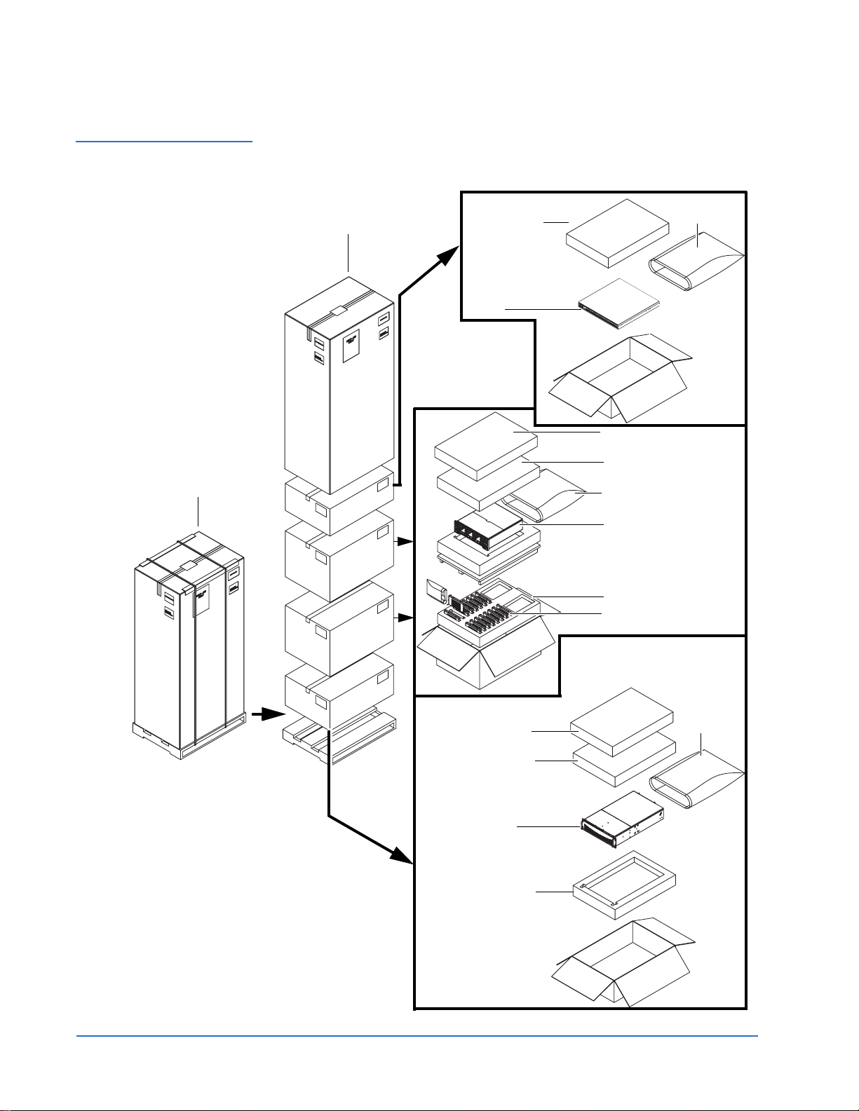
Figure 4 Unpacking the
DX100
DX100 packaging
Cover
Fibre Channel switch
accessory kit
Fibre Channel
switch
Antistatic
bag
Storage array
accessory kit
Top packing foam
Antistatic
bag
Storage array
RAID controller(s)
Hard drive
sleds
Controller
accessory kit
Top
packing foam
Controller
Top
packing foam
10 Unpacking the DX-Series System
Antistatic
bag
Page 11
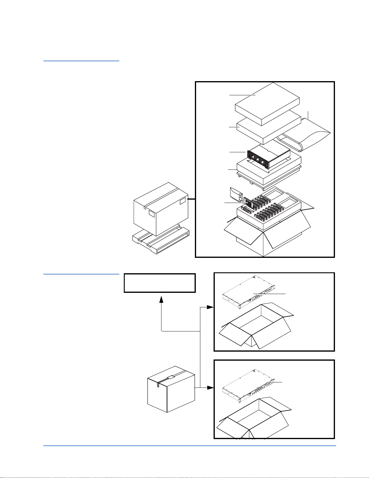
Figure 5 Unpacking
Additional Storage Array(s)
Quantum DX-Series System Unpacking and Installation Instructions
Document 6513502-06 A01
October 2006
Storage array
accessory kit
Antistatic
bag
Top
packing foam
Storage array
Bottom
packing foam
Hard drive
sleds
Figure 6 Unpacking the
Power Kit
Accessory kit: 2 power cords,
2 strain-relief brackets, and 2
Ethernet cables
AC power sequencer
AC power sequencer
Unpacking the DX-Series System 11
Page 12
Quantum DX-Series System Unpacking and Installation Instructions
Document 6513502-06 A01
October 2006
Installing the DX-Series System 0
Installing the DX-Series in a rack consists of the following steps:
• Locating the Mounting Position
• Installing the DX-Series Storage Array
• Installing the Fibre Channel Switch (DX100 Only)
• Installing the Ethernet Switch (DX100 Only)
• Installing the AC Power Sequencers (DX100 Only)
• Installing the DX-Series Controller
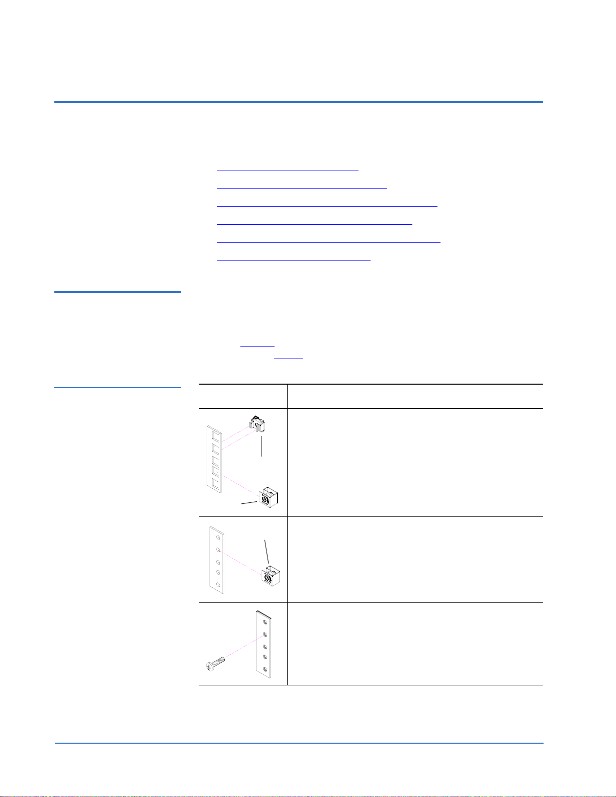
Locating the Mounting Position
Table 2 Rack Hole Types
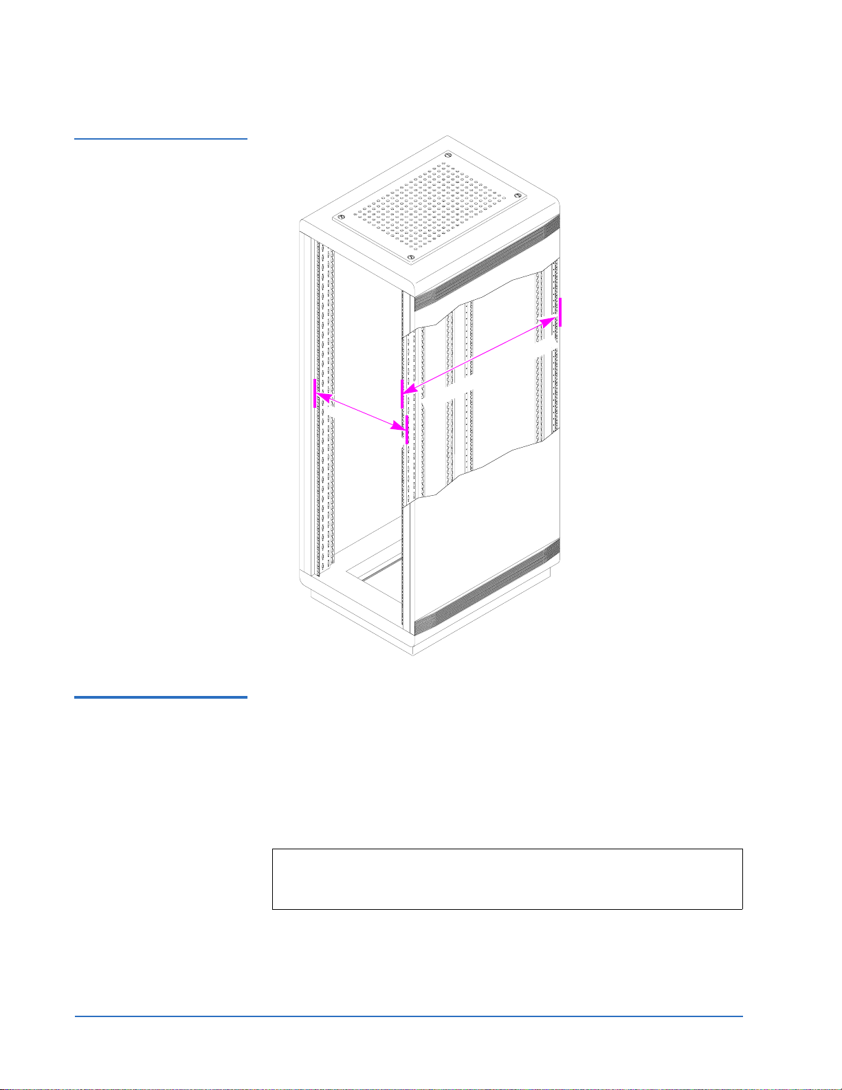
Both components of the DX-Series system are designed to fit in a standard 19
0
inch wide rack.
It is important to the chassis installation to locate the hole pattern in the rack
rails (see figure 7
pattern. Refer to table 2
). The chassis must be installed at the beginning of the hole
for information on common rack hole types.
Figure Description
Square rack holes are the most common type of rack
holes. They can accept either cage nuts which mount
from the back of the rail or clip nuts which clip on from
Cage nut
Clip nut
the side of the rack rail.
Through holes require clip nuts to accept mounting
Clip nut
hardware.
Threaded holes require neither cage or clip nuts to
accept mounting hardware.
12 Installing the DX-Series System
Page 13
Quantum DX-Series System Unpacking and Installation Instructions
Document 6513502-06 A01
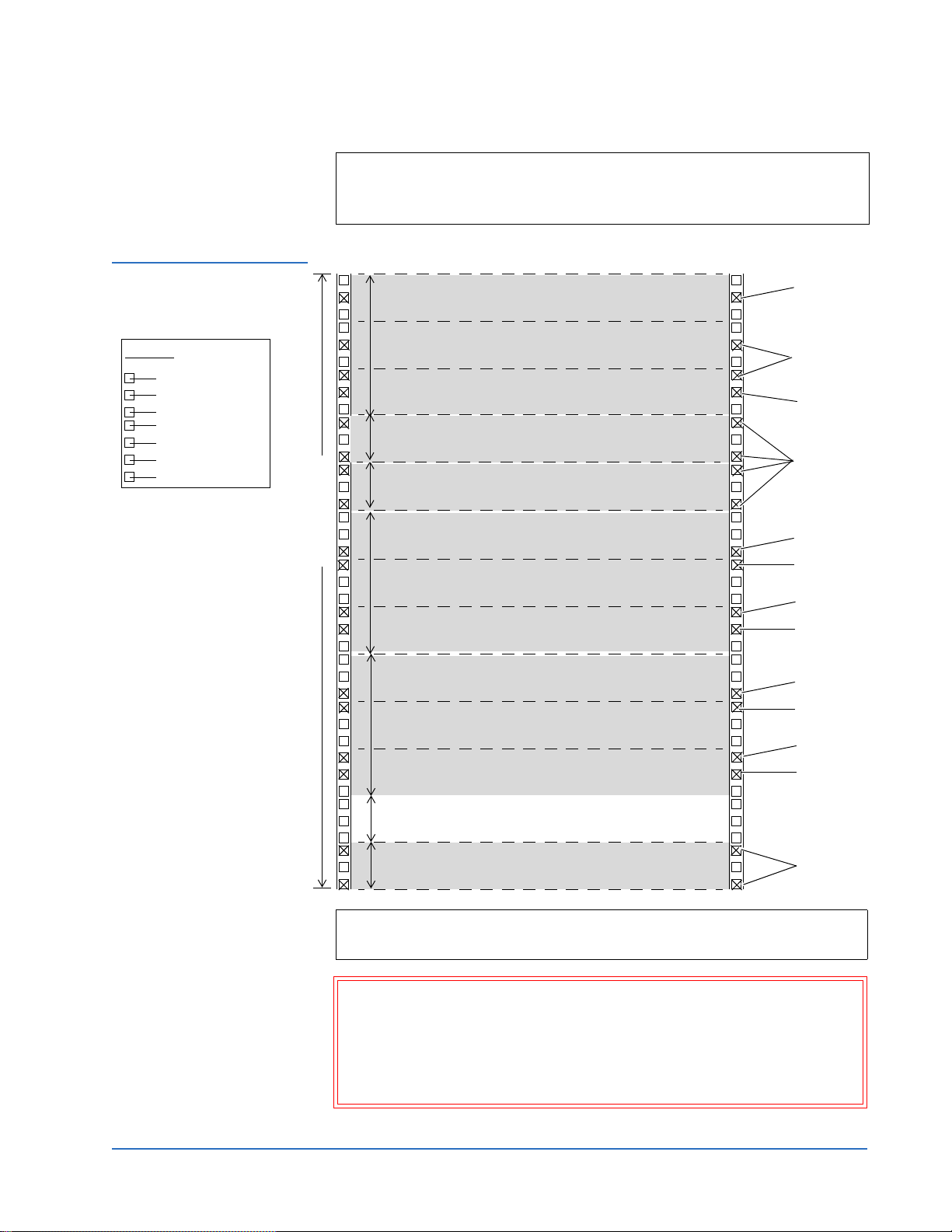
Note: The rails within the rack have a hole pattern that repeats
throughout the rail. X marks the screw positions. Install nut clips
(included in the accessory kit) on the rails if necessary.
October 2006
Figure 7 Rail Hole Pattern
Hole pattern
Top of rack
.312 in (7.92 mm)
.625 in (15.9 mm)
.625 in (15.9 mm)
.5 in (12.7 mm)
.625 in (15.9 mm)
.625 in (15.9 mm)
.5 in (12.7 mm)
*1U = 1.75 in (44.45 mm)
Front panel screws - used to
secure the controller and storage
arrays front panels to the rack
rails.
14U of rack space
3U
1U
1U
3U
3U
1U
1 DX-Series controller module (3U)
1U = 1.75 in
(44.45mm)
1 Ethernet switch (1U)
(DX100 only)
1 Fibre Channel switch (1U)
(DX100 only)
1 DX-Series array module (3U)
1U = 1.75 in
(44.45mm)
Additional DX-Series array module (3U)
1U = 1.75 in
(44.45mm)
1U space minimum between array module
and AC power sequencer (DX100 only)
Front panel
screw
Rail screws
Front panel
screw
Rail screws
Front panel
screw
Rail screw
Front panel
screw
Rail screw
Front panel
screw
Rail screw
Front panel
screw
Rail screw
Rail screws - used to secure the
system components to the rack
rails.
1U
2 or more AC power sequencers
(1U per pair) DX100 only
Rail screws
Note: Leave approximately 6 in. (15 cm) above the controller for access to
the fan modules and Fibre Channel HBAs in the controller.
Warning: If the rack is empty at the time of installation, do NOT install
the DX-Series components too high in the rack. The combined
weight of the components may cause the rack to become “top
heavy” and unstable if installed in the top of an empty rack.
Begin installing the DX-Series components from the bottom of
the rack.
Installing the DX-Series System 13
Page 14
Quantum DX-Series System Unpacking and Installation Instructions
Document 6513502-06 A01
October 2006
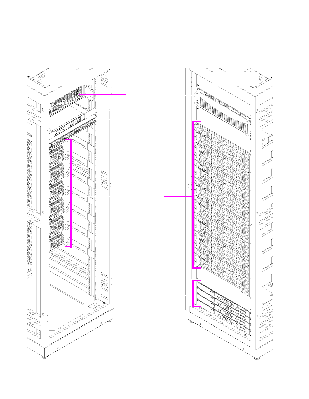
Figure 8 Mounting
Locations
Back View Front View
DX-Series controller (3U)
Ethernet switch
(1U DX100 only)
Fibre Channel Switch
(1U DX100 only)
Storage arrays
(8 shown, 3U each)
B
l
a
n
k
o
f
f
p
l
a
t
e
(
3
U
)
Power sequencers
(1U each, DX100 only)
14 Installing the DX-Series System
Page 15
Quantum DX-Series System Unpacking and Installation Instructions
Document 6513502-06 A01
October 2006
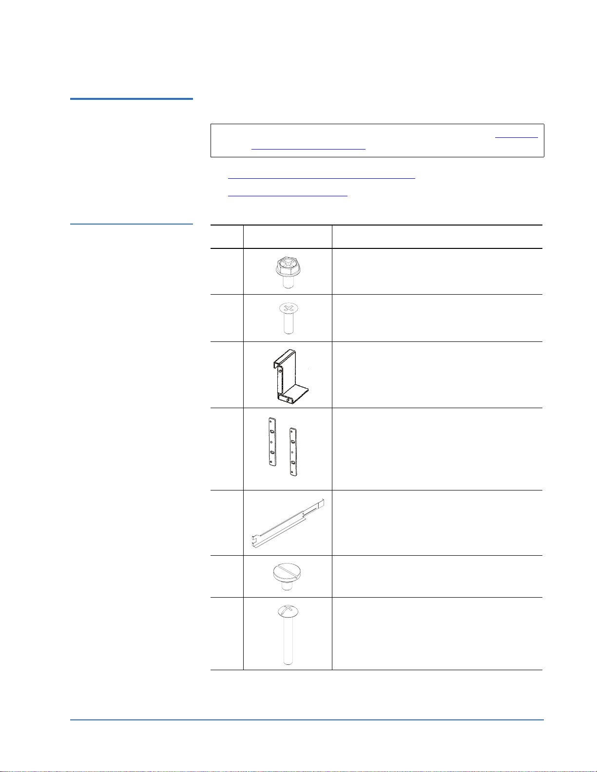
Installing the DX-Series Storage Array
Table 3 Storage Array
Mounting Hardware
Installing the DX-Series storage array consists of the following steps:
0
Note: If this is an upgrade to an existing DX-Series system, see Installing
Additional Storage Arrays on page 41.
• Preparing the Storage Array for installation
• Installing the Storage Array
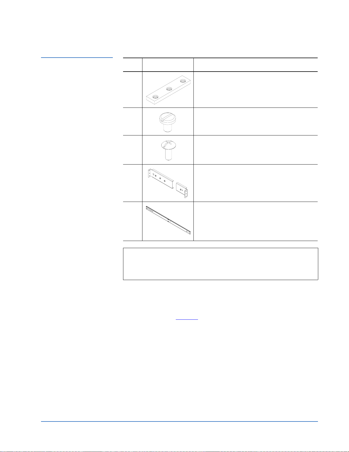
Qty Figure Description
6 32 x 10 pan head PHILLIPS screws
6 32 x 10 flat head PHILLIPS screws
2 Right and left mounting bracket (right shown)
2Right and left mounting spacer (left shown)
2 Right and left support bracket (left shown)
8 10-32 x .50 in. slotted screws
4 10-32 x 1.25 in. (M5 x 32 metric also provided)
black PHILLIPS screws
Installing the DX-Series System 15
Page 16
Quantum DX-Series System Unpacking and Installation Instructions
Document 6513502-06 A01
October 2006
Preparing the Storage Array for installation 0
1 Install a spacer on each side with 6-32 x 10 flat head PHILLIPS screws
provided in the storage array accessory kit (see figure 9
Figure 9 Installing the
Mounting Spacers
Mounting spacer
).
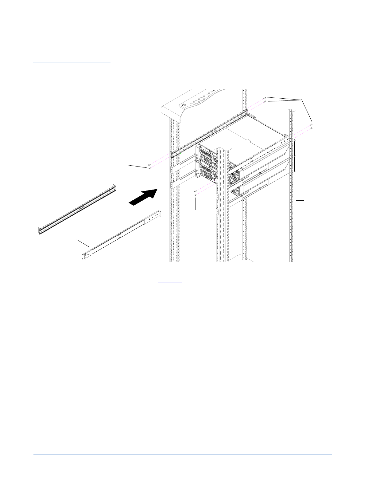
Installing the Storage Array 0
1 Install the left and right storage array support brackets at the beginning of
a hole pattern (see Locating the Mounting Position
on page 12) and
loosely install two 10-32 x .50 in. slotted screws on each rail at the front
and back of the rack (see figure 10
).
Note: The support brackets must be installed on the inside rack rails.
Note: The support brackets extend to accommodate rack depths of 30
to 36 in. (76.2 to 91 cm).
16 Installing the DX-Series System
Page 17
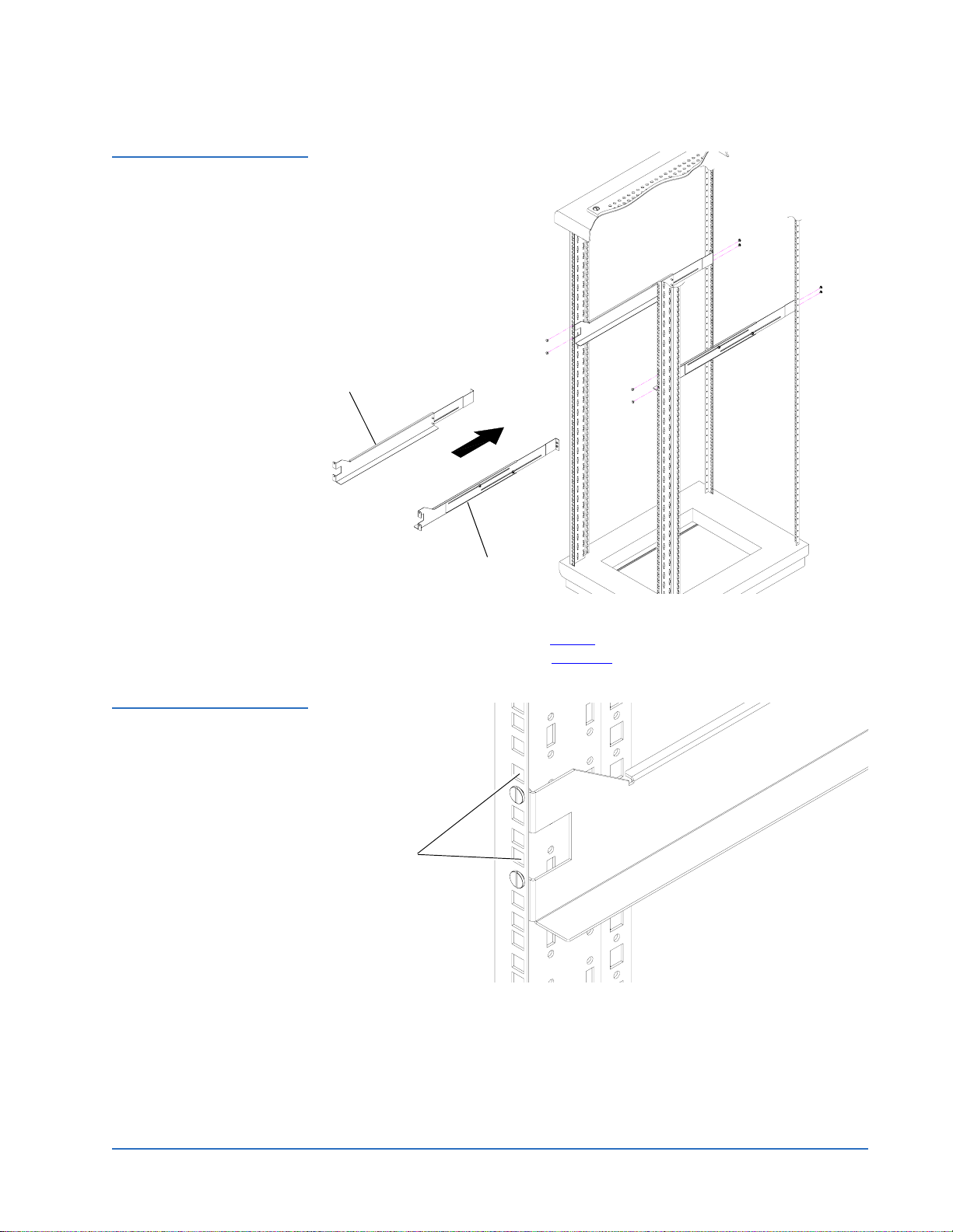
Figure 10 Installing the
Storage Array Support
Brackets
Quantum DX-Series System Unpacking and Installation Instructions
Document 6513502-06 A01
October 2006
Left support bracket
Figure 11 Storage Array
Mounting Holes
Right support bracket
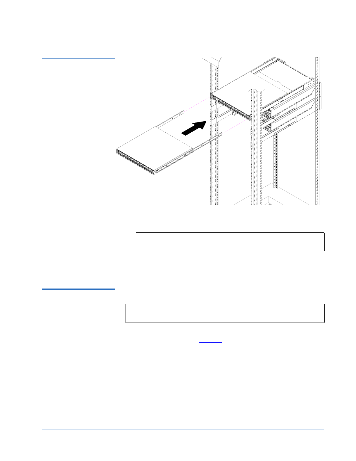
2 With the support brackets installed, prepare the storage array mounting
holes if necessary. Refer to table 2
required for your rack (see figure 11
Storage array
mounting holes
Left rail shown
to determine the type of hardware
for hole location).
3 Tighten the screws securing the front and back of the support brackets.
4 Tighten adjustment screws on each rail.
5 Carefully slide the storage array into the rack.
Installing the DX-Series System 17
Page 18
Quantum DX-Series System Unpacking and Installation Instructions
Document 6513502-06 A01
October 2006
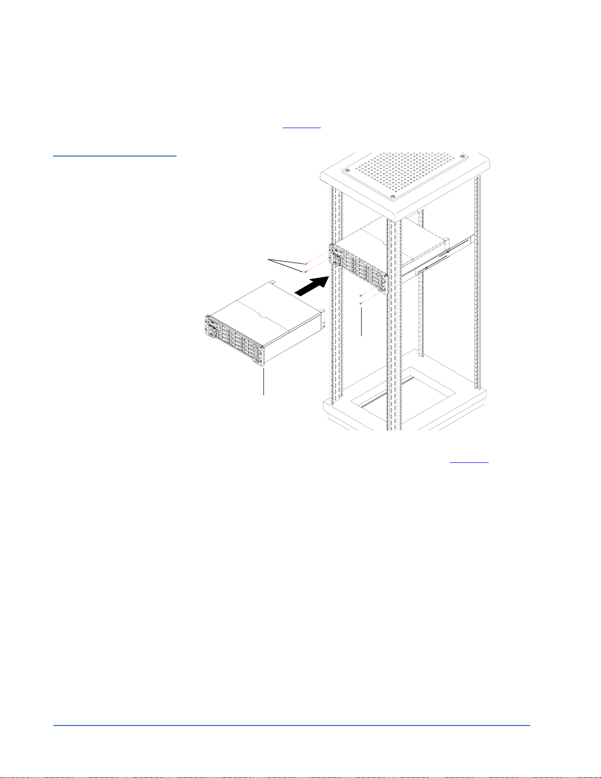
6 Secure the storage array to the rack with two 10-32 x 1.25 in. (M5 x 32
metric also provided) black PHILLIPS screws on each side of the front of
the chassis. (see figure 12
Figure 12 Securing the
Storage Array to the Rack
Screws
).
Screws
Storage array
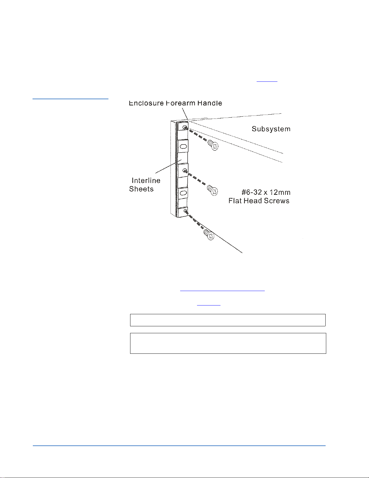
7 Install the right and left mounting brackets with 6-32 x 10 pan head
screws provided in the storage array accessory kit (see figure 13
).
18 Installing the DX-Series System
Page 19
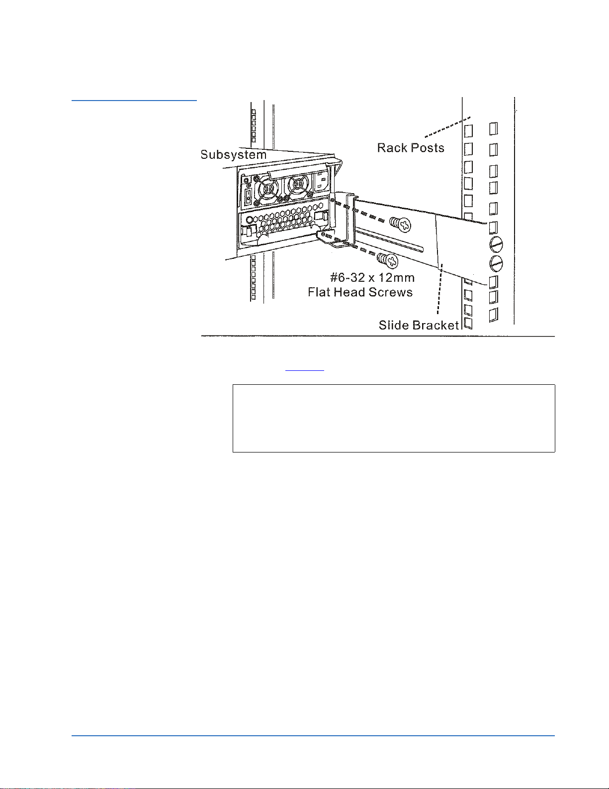
Figure 13 Installing the
Mounting Brackets
Quantum DX-Series System Unpacking and Installation Instructions
Document 6513502-06 A01
October 2006
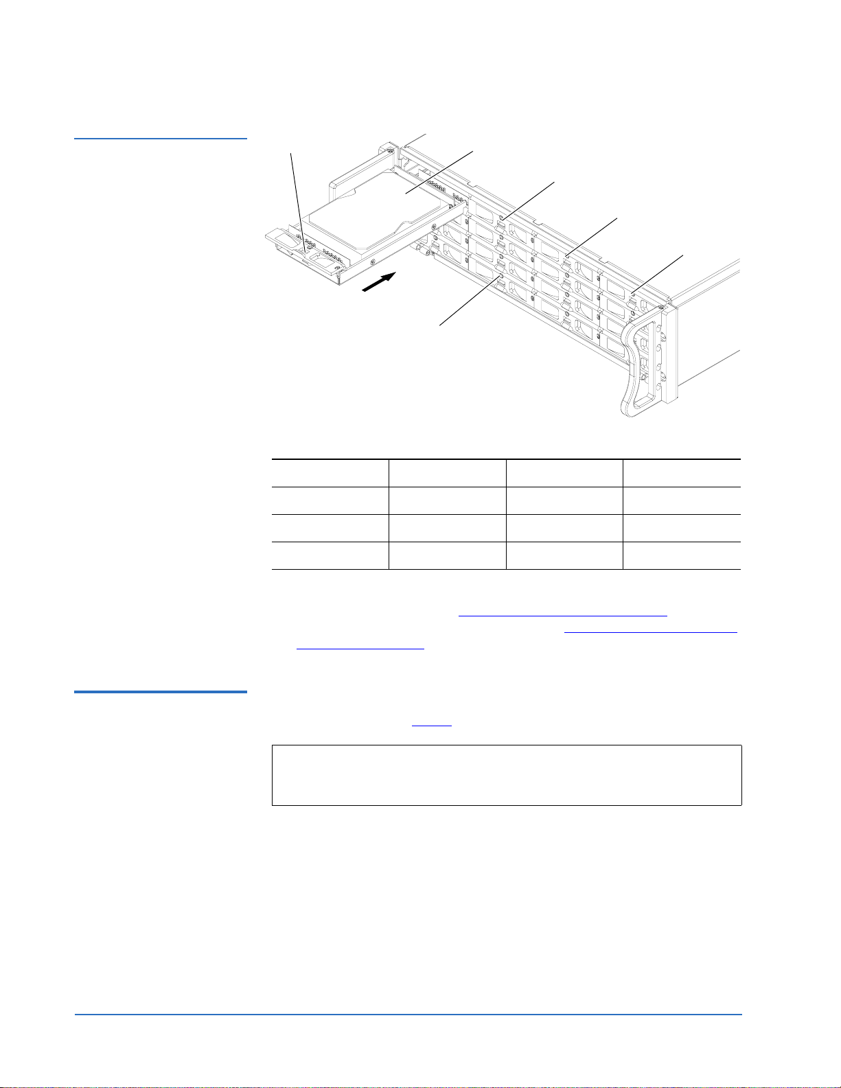
8 Install each of the hard drive sleds into the DX-Series storage array
chassis (see figure 14
).
Note: The hard drives must be installed in the proper sequence since
RAID sets have already been established at the factory. Refer
to the label on the bottom of the drive sled for the drive
number. The hard drives must also be installed in the array in
which it was configured.
Installing the DX-Series System 19
Page 20
Quantum DX-Series System Unpacking and Installation Instructions
Document 6513502-06 A01
October 2006
Figure 14 Installing the
Hard Drive Sleds
Door latch
Locking screw
Drive sled 1
Drive sled 2
Drive sled 3
Drive sled 4
Storage Array Drive Bay Numbering
1234
5678
9 101112
Installing the Fibre Channel Switch (DX100 Only)
13 14 15 16
The DX-Series storage array is now installed in the rack. If this is a DX30
installation, continue with Installing the DX-Series Controller
on page 27.
If this is a DX100 installation, continue with Installing the Fibre Channel
Switch (DX100 Only).
To install the Fibre Channel switch, refer to the Fiber Channel switch
hardware described in table 4
and the following instructions:
0
Note: The Fibre Channel switch may be slightly different from the switch
documented in this procedure. The installation procedure should
be similar.
20 Installing the DX-Series System
Page 21
Quantum DX-Series System Unpacking and Installation Instructions
Document 6513502-06 A01
October 2006
Table 4 Fibre Channel
Switch Mounting Hardware
Qty Figure Description
4 Mounting plates (used only with rack rails
with through holes or threaded holes)
14 Slotted screws
12 PHILLIPS screws (only 8 used for front and
back rack mounting)
4 Front and back mounting brackets (left
shown)
2 Right and left support bracket (left shown)
Note: To accommodate the Fibre Channel cabling connections, the Fibre
Channel switch must be installed with the Fibre Channel ports
facing the back of the rack. A 2U blank-off plate is provided to
cover the front portion of the rack.
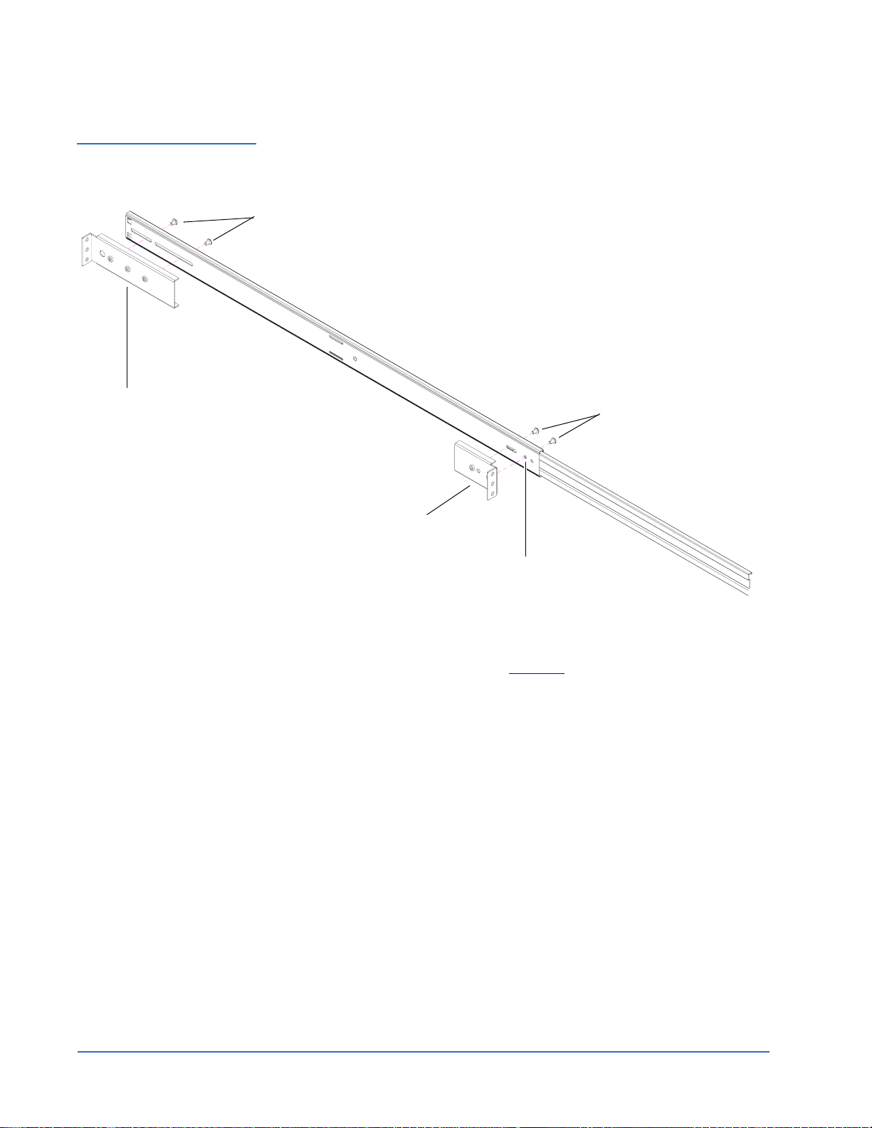
1 Loosely assemble the left and right support brackets with two slotted
screws on the front and the back of the bracket. DO NOT TIGHTEN. You
must pull the slide out of the support brackets to gain access to the
mounting holes. The back mounting bracket must be installed in the
second hole (see figure 15
).
Installing the DX-Series System 21
Page 22
Quantum DX-Series System Unpacking and Installation Instructions
Document 6513502-06 A01
October 2006
Figure 15 Assembling the
Right and Left Support
Brackets
slotted screws
Front mounting bracket
slotted screws
Left support bracket shown
back mounting bracket
Second mounting hole
2 Remove the right and left slide rails from the support brackets.
3 Install the right and left slide rails on the Fibre Channel switch with three
slotted screws on each side (see figure 16
).
22 Installing the DX-Series System
Page 23
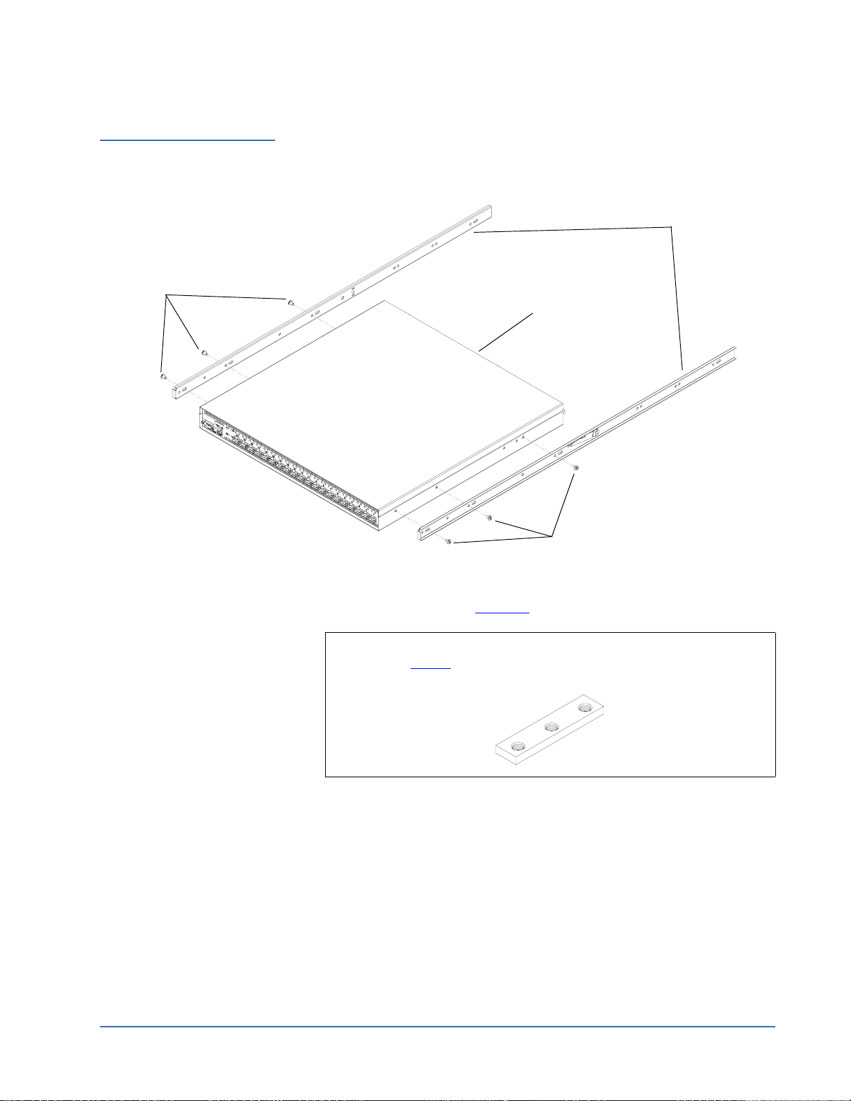
Figure 16 Installing the
Fibre Channel Switch Slide
Rails
Slotted screws
Quantum DX-Series System Unpacking and Installation Instructions
Document 6513502-06 A01
October 2006
Slide rails
Fibre Channel switch
Switch may be visually different
Slotted screws
4 From the back of the rack, install the Fibre Channel switch support
brackets with two PHILLIPS screws on each bracket in the front and in
the back of the rack (see figure 17
).
Note: To support bracket installation in racks with through holes
(see table 2
), mounting plates are provided with the switch
accessory kit for use behind the rail mounting positions.
Installing the DX-Series System 23
Page 24
Quantum DX-Series System Unpacking and Installation Instructions
Document 6513502-06 A01
October 2006
Figure 17 Installing the
Right and Left Support
Brackets in the Rack
Back of
rack
Screws
Screws
Screws
Front of
rack
Support brackets
5 Slide the Fibre Channel switch into the support brackets in the back of the
rack (see figure 18
).
24 Installing the DX-Series System
Page 25
Quantum DX-Series System Unpacking and Installation Instructions
Document 6513502-06 A01
October 2006
Figure 18 Sliding the Fibre
Channel Switch into the
Support Brackets
Switch may be visually different
Fibre Channel switch
6 Install 2U blank-off plate in front of rack covering the space taken by the
Fibre Channel switch and Ethernet switch.
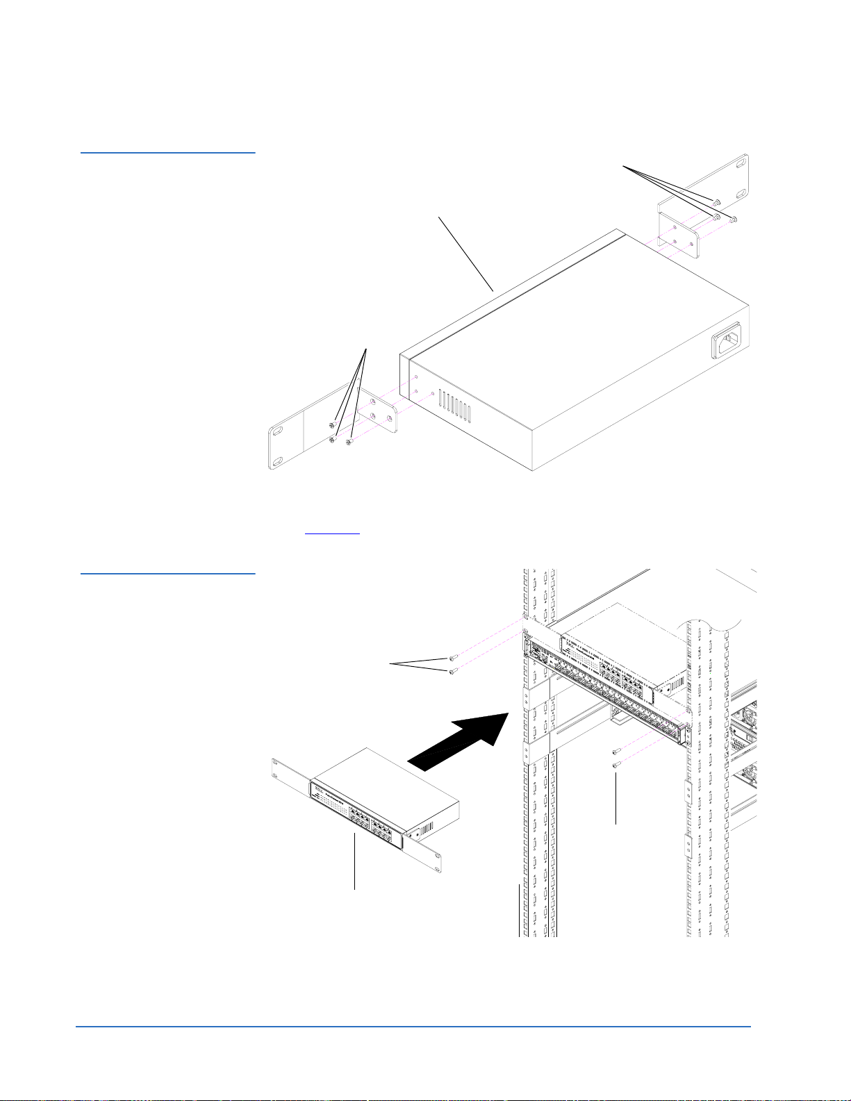
Installing the Ethernet Switch (DX100 Only)
Note: Install two 10-32 x .50 in. screws in the rack under the right
and left top corners of the 2U blank-off plate.
Repeat this procedure for an additional Fibre Channel switch in a second
rack to support more than 8 storage arrays.
To install the Ethernet switch:
0
Note: To accommodate the Ethernet cabling connections, the Ethernet
switch must be installed with the ports facing the back of the rack.
1 Install the mounting ears on to the Ethernet switch with three PHILLIPS
screws on each side (see figure 19
).
Installing the DX-Series System 25
Page 26
Quantum DX-Series System Unpacking and Installation Instructions
Document 6513502-06 A01
October 2006
Figure 19 Installing the
Ethernet Mounting Ears
PHILLIPS screws
Ethernet switch
PHILLIPS screws
2 Install the Ethernet switch into the back of the rack directly above the
Fibre Channel switch and secure with two screws on each side (see
figure 20
).
Figure 20 Installing the
Ethernet Switch into the
Rack
Screws
Screws
Ethernet switch
26 Installing the DX-Series System
Page 27
Quantum DX-Series System Unpacking and Installation Instructions
Document 6513502-06 A01
October 2006
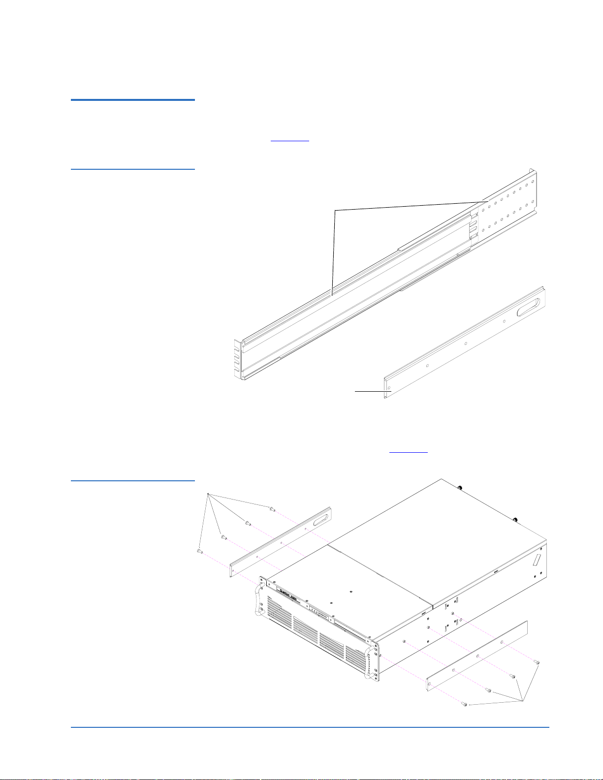
Installing the DX-Series Controller
Figure 21 DX-Series
Controller Rails
To install the DX-Series controller:
0
1 Each DX-Series controller rail is shipped in three pieces, six total for both
rails (see figure 21
Mounting brackets (2 pieces)
Controller chassis mounting plate
(one piece)
).
Figure 22 Installing the
Controller Chassis
Mounting Plates
2 Install the chassis mounting plate on each side of the controller with four
10-32 x .50 in. PHILLIPS screws (see figure 22
Screws
).
Screws
Installing the DX-Series System 27
Page 28

Quantum DX-Series System Unpacking and Installation Instructions
Document 6513502-06 A01
October 2006
3 Determine the depth of the rack (30 in, 76.2 cm minimum) and assemble
each DX-Series controller rail with two PHILLIPS screws and locking
plate at the appropriate depth (see figure 23
Figure 23 Assembling the
Controller Rails
Locking plate
).
Screws
Locking plate
4 Install the DX-Series controller rails into the rack with four 10-32 x .50 in.
PHILLIPS screws on each side (two in the front and two in the back) (see
figure 24
).
Note: To support bracket installation in racks with through holes
(see table 2
), mounting plates are provided with the switch
accessory kit for use behind the rail mounting positions.
28 Installing the DX-Series System
Page 29

Figure 24 Installing the
DX-Series Controller Rails
Quantum DX-Series System Unpacking and Installation Instructions
Document 6513502-06 A01
October 2006
Screws
Screws
Left controller rail
Screws
Right controller rail
5 Slide the DX-Series controller into the support brackets in the rack and
secure with two black 10-32 x .75 in. PHILLIPS screws on each side of the
controller (see figure 25
).
Installing the DX-Series System 29
Page 30

Quantum DX-Series System Unpacking and Installation Instructions
Document 6513502-06 A01
October 2006
Figure 25 Installing the
DX-Series Controller
Screws
Screws
Installing the AC Power Sequencers (DX100 Only)
Controller
The DX100 storage arrays must be powered on in the correct order to avoid
inrush current overflows. To achieve this, the power sequencers are installed
0
to automatically power on the storage arrays in the correct order.
Caution: Turn off the AC power sequencer circuit breakers prior to
installing.
Installing the AC power sequencers consists of the following steps:
• Configuring the AC Power Sequencer
• Cabling and Installing the AC Power Sequencer
Configuring the AC Power Sequencer 0
1 The AC power sequencers must have a specific strapping ID set prior to
operating. Use the up and down buttons located on the back of the AC
power sequencer to set the strapping ID to 0 for the first power sequencer,
1 for the second sequencer, 2 for the third power sequencer, and 3 for the
fourth power sequencer (see figure 26
).
30 Installing the DX-Series System
Page 31

Figure 26 Setting the
Power Sequencer
Strappin g ID s
Daisy chain strapping In
Quantum DX-Series System Unpacking and Installation Instructions
Document 6513502-06 A01
October 2006
Ethernet port to
Ethernet switch
Strapping ID
selector
Daisy chain strapping Out
Figure 27 Removing the
Mounting Brackets
2 Remove the three PHILLIPS screws securing the mounting brackets on
each side of the power sequencer (see figure 27
Screws
).
Screws
Installing the DX-Series System 31
Page 32

Quantum DX-Series System Unpacking and Installation Instructions
Document 6513502-06 A01
October 2006
3 Install the hold down mounting assembly with five PHILLIPS screws on
each side of the power sequencer (see figure 28
Figure 28 Installing the
Hold Down Bracket
Assembly
Left mounting bracket
).
Hold down bracket
Cabling and Installing the AC Power Sequencer 0
To simplify installation, the power cords for the AC power sequencer,
controller, Ethernet switch, Fibre Channel switch, and storage arrays must be
installed outside of the rack. After all cords have been connected, the power
sequencers are installed.
To cable and install the AC power sequencers:
1 Remove the two PHILLIPS screws securing the power connector to the
power sequencer (see figure 29
32 Installing the DX-Series System
Right mounting bracket
).
Page 33

Quantum DX-Series System Unpacking and Installation Instructions
Document 6513502-06 A01
October 2006
Figure 29 Removing the
AC Power Connector
Screws
Figure 30 Installing the
Cable Clamp and Power
Cable
AC power connector
Screws
2 Install the cable clamp on the power sequencer using two pan head
PHILLIPS screws provided in the accessory kit (see figure 30
).
Screws
Cable clamp
3 Install the AC power cable through the cable clamp and into the AC
power sequencer. Tighten the cable clamp with the tension screw to
secure the power cable (see figure 31
).
Note: A rubber shim is included with the cable clamp for power
cables smaller than the cable clamp.
Installing the DX-Series System 33
Page 34

Quantum DX-Series System Unpacking and Installation Instructions
Document 6513502-06 A01
October 2006
Figure 31 Installing the AC
Power Cable
Tension screw
AC power cable
Figure 32 Connecting the
First Power Connector
4 Connect the first power connector on the controller to outlet J1 on the first
AC power sequencer and secure with a tie wrap (see figure 32
Tie wrap
First power connector
).
5 Connect the second power connector on the controller to outlet J1 on the
second AC power sequencer and secure with a tie wrap.
34 Installing the DX-Series System
Page 35

Quantum DX-Series System Unpacking and Installation Instructions
6 Connect the following power cables for systems with two to sixteen
storage arrays (see table 5
Table 5 Storage Array
Power Cabling
Power Sequencer Ports
and figure 33 through figure 38):
Document 6513502-06 A01
October 2006
Sequencer 1
Sequencer 2
Sequencer 3
Sequencer 4
Sequencer 5
Sequencer 6
Sequencer 7
AC Input J1 J2 J3
Primary AC Controller FC
switch
#1
Secondary AC Controller FC
switch
#1
Primary AC
Secondary AC
Primary AC FC
switch
#2
Secondary AC FC
switch
#2
Primary AC
Eth.
switch
J4 J5 J6 J7 J8
Storage
array 1
(first
connector)
Storage
array 1
(second
connector)
Storage
array 5
(first
connector)
Storage
array 5
(second
connector)
Storage
array 9
(first
connector)
Storage
array 9
(second
connector)
Storage
array 13
(first
connector)
Storage
array 2
(first
connector)
Storage
array 2
(second
connector)
Storage
array 6
(first
connector)
Storage
array 6
(second
connector)
Storage
array 10
(first
connector)
Storage
array 10
(second
connector)
Storage
array 14
(first
connector)
Storage
array 3
(first
connector)
Storage
array 3
(second
connector)
Storage
array 7
(first
connector)
Storage
array 7
(second
connector)
Storage
array 11
(first
connector)
Storage
array 11
(second
connector)
Storage
array 15
(first
connector)
Storage
array 4
(first
connector)
Storage
array 4
(second
connector)
Storage
array 8
(first
connector)
Storage
array 8
(second
connector)
Storage
array 12
(first
connector)
Storage
array 12
(second
connector)
Storage
array 16
(first
connector)
Sequencer 8
Secondary AC
Storage
array 13
(second
connector)
Storage
array 14
(second
connector)
Storage
array 15
(second
connector)
Storage
array 16
(second
connector)
7 Connect strapping port Out on the first AC power sequencer to strapping
port
In on the second AC power sequencer.
8 If four AC power sequencers are present, connect strapping port
Out on
the second AC power sequencer to strapping port In on the third AC
power sequencer.
9 Connect strapping port
strapping port
In on the fourth AC power sequencer.
Out on the third AC power sequencer to
10 If AC power sequencers five through eight are present in a second rack:
a Connect strapping port
first rack) to strapping port
Installing the DX-Series System 35
Out on the fourth AC power sequencer (in the
In on the fifth AC power sequencer.
Page 36

Quantum DX-Series System Unpacking and Installation Instructions
Document 6513502-06 A01
October 2006
b Connect strapping port Out on the fifth AC power sequencer to
strapping port
In on the sixth AC power sequencer.
Figure 33 DX100 Power
Cabling (Controller, Ethernet
and Fibre Channel Switch)
Primary AC
power source (separate circuit)
c Connect strapping port
strapping port
In on the seventh AC power sequencer.
d Connect strapping
strapping port
In on the eight AC power sequencer.
Out on the sixth AC power sequencer to
Out on the seventh AC power sequencer to
Note: Odd and even numbered AC power sequencers should be on
separate circuits for redundancy.
Note: The storage arrays MUST be connected to the exact outlets
specified to allow the software discovery to function correctly.
Ethernet switch
First AC power sequencer
out
in
J8J7J6J5J4J3J2J1AC input
CAT5
cable
Controller
Secondary AC
power source (separate circuit)
Second AC power sequencer
Note: Connect AC inputs to an external AC power source on a
dedicated circuit. Ensure that the AC inputs are secured to the
power sequencers with cable retention clamps.
36 Installing the DX-Series System
Fibre Channel
Switch
in
J8J7J6J5J4J3J2J1AC input
out
CAT5
cable
Page 37

Figure 34 DX100 Power
Cabling (One to Four
Storage Arrays)
Primary AC
power source
(separate circuit)
First AC power sequencer
Quantum DX-Series System Unpacking and Installation Instructions
Document 6513502-06 A01
October 2006
out
in
J8J7J6J5J4J3J2J1AC input
Storage array 3Storage array 1
Secondary AC
power source
(separate circuit)
Second AC power sequencer
Figure 35 DX100 Power
Cabling (Five to Eight
Storage Arrays)
Primary AC
power source (separate circuit)
Third AC power sequencer
Storage array 2
Storage array 4
CAT5
cable
out
in
J8J7J6J5J4J3J2J1AC input
To the Out port of the
second power sequencer
out
in
J8J7J6J5J4J3J2J1AC input
Secondary AC
power source (separate circuit)
Fourth AC power sequencer
Storage array 7Storage array 5
Storage array 6
Storage array 8
CAT5
cable
in
J8J7J6J5J4J3J2J1AC input
out
Installing the DX-Series System 37
Page 38

Quantum DX-Series System Unpacking and Installation Instructions
Document 6513502-06 A01
October 2006
Figure 36 Cabling Second
Fibre Channel Switch
Primary AC
power source (separate circuit)
Secondary AC
power source (separate circuit)
Fifth AC power sequencer
Sixth AC power sequencer
To the Out port of the
fourth power sequencer
CAT5
cable
out
in
J8J7J6J5J4J3J2J1AC input
2nd Fibre
Channel Switch
CAT5
cable
out
in
J8J7J6J5J4J3J2J1AC input
Note: Connect AC inputs to an external AC power source on a
dedicated circuit. Ensure that the AC inputs are secured to the
power sequencers with cable retention clamps.
38 Installing the DX-Series System
Page 39

Quantum DX-Series System Unpacking and Installation Instructions
T
Document 6513502-06 A01
October 2006
Figure 37 DX100 Power
Cabling (Nine to Twelve
Storage Arrays)
Primary AC
power source
(separate circuit)
Secondary AC
power source
(separate circuit)
Fifth AC power sequencer
Sixth AC power sequencer
Storage array 11Storage array 9
Storage array 10
o the Out port of the
fourth power sequencer
out
in
J8J7J6J5J4J3J2J1AC input
Storage array 12
CAT5
cable
out
in
J8J7J6J5J4J3J2J1AC input
Figure 38 DX100 Power
Cabling (Thirteen to
Sixteen Storage Arrays)
Primary AC
power source (separate circuit)
Secondary AC
power source (separate circuit)
Seventh AC power sequencer
Storage array 15Storage array 13
Storage array 14
To the Out port of the
sixth power sequencer
out
in
J8J7J6J5J4J3J2J1AC input
Storage array 16
CAT5
cable
Eighth AC power sequencer
Installing the DX-Series System 39
out
in
J8J7J6J5J4J3J2J1AC input
Page 40

Quantum DX-Series System Unpacking and Installation Instructions
Document 6513502-06 A01
October 2006
11 Starting in the back of the rack, install the AC power sequencers with four
PHILLIPS screws (two power sequencers for up to four storage arrays,
four power sequencers for five to eight storage arrays, six power
sequencers for up to twelve storage arrays, and eight power sequencers
for thirteen to sixteen storage arrays). The first, third, fifth, and seventh
AC power sequencers are installed in the front of the rack and the second,
fourth, sixth, and eight AC power sequencers are installed in the back of
the rack (see figure 39
).
Note: If you have enough space in the rack, install all of the
sequencers in the front of the rack with sequencer 1 on top.
This allows easier access to the power connectors.
Figure 39 Installing the AC
Power Sequencers
AC power sequencer
Back of rack
Screws
2nd/6th AC power
sequencer
Screws
1st/5th AC power
sequencer
3rd/7th AC power
sequencer
4th/8th AC power
sequencer
40 Installing the DX-Series System
Page 41

Quantum DX-Series System Unpacking and Installation Instructions
Document 6513502-06 A01
October 2006
Installing Additional Storage Arrays 0
To install additional storage arrays:
Note: If this is an upgrade to an existing DX-Series system, the additional
storage arrays must be installed below the original DX-Series
system.
1 Refer to Installing the DX-Series Storage Array
Tech Tip: If more than two storage arrays are to be installed, start
the installation with the bottom storage array and work
up.
on page 15.
Cabling the DX-Series System 0
There are several possible cabling scenarios for the DX-Series system
depending on the installation. Refer to the following sections for cabling
examples:
• Installing the SFP Connectors
• Verifying Storage Array Dip Switches
• Cabling a DX30
• Cabling a DX100
• Power Cabling
Installing the SFP Connectors
Caution: Use extreme care when handling the LC-to-LC Fibre Channel
cables. Do not pinch the cables and keep the connector ends
free from debris.
Both the Fibre Channel switch and the storage array(s) need SFP (Small Form-
0
Factor Pluggable) connectors installed prior to connecting Fibre Channel
cables. The SFP connectors are located in both the Fibre Channel switch and
storage array accessory kits.
Install the following SFP connectors:
1 Fibre Channel switch ports (see figure 40
connections (DX100 requires four SFPs plus two for every installed
storage array).
Installing Additional Storage Arrays 41
) that have Fibre Channel cable
Page 42

Quantum DX-Series System Unpacking and Installation Instructions
Document 6513502-06 A01
October 2006
2 Storage array RAID controllers (see figure 41) that have Fibre Channel
cable connections (channel 0 on the top left of the storage array and
channel 1 on the upper right of the storage array).
Figure 40 Installing the SFPs
in the Fibre Channel Switch
(DX100 Only)
Required SFP for
controller connection
1st or 9th
storage array
28!#4 ,).+
3rd or 11th
storage array
Required SFP for
controller connection
Figure 41 Installing the
SFP(s) in the Connection
Modules
5th or 13th
storage array
7th or 15th
storage array
Required SFP for
controller connection
2nd or 10th
storage array
0/7%2 3934%-
4%-0
/.
&!5,4
&!5,4
Required SFP for
controller connection
6th or 14th
storage array
4th or 12th
storage array
8th or 16th
storage array
SFP
42 Cabling the DX-Series System
Page 43

Quantum DX-Series System Unpacking and Installation Instructions
Document 6513502-06 A01
October 2006
Verifying Storage Array Dip Switches
Figure 42 Verifying the
Storage Array Dip
Switches
Each storage array has a set of dip switches located on the back of the array in
0
the upper left-hand corner. The switches are set in manufacturing, but verify
the settings prior to cabling the system (see figure 42
).
All dip switches are enabled except for dip switch 4.
Cabling the DX-Series System 43
Page 44

Quantum DX-Series System Unpacking and Installation Instructions
Document 6513502-06 A01
October 2006
Cabling a DX30 0 To cable a DX30 with up to four storage arrays:
1 Connect the power cords, LC-to-LC Fibre Channel cables, and Ethernet
network connection as shown in table 6
and figure 43.
Table 6 DX30 Fibre
Channel and Ethernet
Cabling
Controller Connections (see figure 43) Storage Array/Network
FC port 1 Storage array 1, FC-CH0 (right-
hand port)
FC port 2 Storage array 2, FC-CH0 (right-
hand port)
FC port 3 Storage array 3, FC-CH0 (right-
hand port)
FC port 4 Storage array 4, FC-CH0 (right-
hand port)
FC port 5 Customer FC host
FC port 6 Additional FC host
Eth0 Customer network
Eth1 Not used
Note: An additional Fibre Channel cable can be connected to port 6
on the dual port Fibre Channel HBA to support multiple
customer hosts or to improve throughput capability.
Note: The medium changer (robot) and three virtual tape drives, by
default, are presented on port 5 and the remaining three
virtual tape drives are presented on port 6. Refer to
Configuring the Fibre Channel Settings
description of how to re-map the devices to Fibre Channel
ports.
44 Cabling the DX-Series System
on page 75 for a
Page 45

Figure 43 Connecting the
DX30 Cables (Four
Storage Arrays)
Quantum DX-Series System Unpacking and Installation Instructions
Document 6513502-06 A01
October 2006
Controller
AC Power
connectors
Storage array 1
Storage array 2
AC Power
connector
Ch0 Ch0
Ch0 Ch0
Customer network
Eth1
Eth0
Fibre Channel
connection
Fibre Channel
connection
Fibre Channel host(s)
5
6
Ch1 Ch1
Ch1 Ch1
Dual port Fibre
Channel HBA
Quad port Fibre
Channel HBA
1
2
3
4
AC Power
connectors
Storage array 3
AC Power
connectors
Storage array 4
Ch0 Ch0
Ch0 Ch0
Fibre Channel
connection
Fibre Channel
connection
Ch1 Ch1
Ch1 Ch1
AC Power
connectors
Cabling the DX-Series System 45
Page 46

Quantum DX-Series System Unpacking and Installation Instructions
Document 6513502-06 A01
October 2006
Cabling a DX100 0 To cable a DX100 system:
1 Connect the power cords, LC-to-LC Fibre Channel cables, and Ethernet
network connection for the controller and storage arrays as shown in
table 7
, table 8, table 9 and figure 44, figure 45, figure 46, and figure 47.
Refer to figure 34
and figure 35 for AC power connections.
Table 7 DX100 Fibre Channel
and Ethernet Cabling
(Controller to FC Switch)
Controller Connections
(see figure 44
) FC Switch/Network
FC port 1 FC Switch 1, port 1
FC port 2 FC Switch 2, port 1 (9 to 16 arrays only)
FC port 3 FC Switch 2, port 11 (9 to 16 arrays only)
FC port 4 FC Switch 1, port 11
FC port 5 Customer FC host
FC port 6
FC port 7
FC port 8
FC port 9
Additional FC hosts
FC port 10
FC port 11
FC port 12
FC port 13 FC Switch 1, port 6
FC port 14 FC Switch 2, port 6 (9 to 16 arrays only)
FC port 15 FC Switch 2, port 16 (9 to 16 arrays only)
FC port 16 FC Switch 1, port 16
Eth0 Customer network
Eth1 Ethernet switch
Note: Additional Fibre Channel cables can be connected to ports 6
through 12 on the dual port Fibre Channel HBAs to support
multiple customer hosts or to improve throughput capability.
46 Cabling the DX-Series System
Page 47

Quantum DX-Series System Unpacking and Installation Instructions
Document 6513502-06 A01
October 2006
Note: The medium changer (robot) and three virtual tape drives, by
default, are presented on port 5 and the remaining three
virtual tape drives are presented on port 6. Refer to
Configuring the Fibre Channel Settings
on page 75 for a
description of how to re-map the devices to Fibre Channel
ports.
Table 8 DX100 Fibre
Channel and Cabling
(Storage Arrays 1 through 8)
Connection From: To:
Storage array 1 Primary connection module
FC switch 1, port 2
FC- Ch0 (right-hand port)
Secondary connection module
FC switch 1, port 12
FC- Ch1 (left-hand port)
Storage array 2 Primary connection module
FC switch 1, port 7
FC- Ch0 (right-hand port)
Secondary connection module
FC switch 1, port 17
FC- Ch1 (left-hand port)
Storage array 3 Primary connection module
FC switch 1, port 3
FC- Ch0 (right-hand port)
Secondary connection module
FC switch 1, port 13
FC- Ch1 (left-hand port)
Storage array 4 Primary connection module
FC switch 1, port 8
FC- Ch0 (right-hand port)
Secondary connection module
FC switch 1, port 18
FC- Ch1 (left-hand port)
Storage array 5 Primary connection module
FC switch 1, port 4
FC- Ch0 (right-hand port)
Secondary connection module
FC- Ch1 (left-hand port)
Storage array 6 Primary connection module
FC- Ch0 (right-hand port)
Secondary connection module
FC- Ch1 (left-hand port)
Storage array 7 Primary connection module
FC- Ch0 (right-hand port)
Secondary connection module
FC- Ch1 (left-hand port)
Cabling the DX-Series System 47
FC switch 1, port 14
FC switch 1, port 9
FC switch 1, port 19
FC switch 1, port 5
FC switch 1, port 15
Page 48

Quantum DX-Series System Unpacking and Installation Instructions
Document 6513502-06 A01
October 2006
Connection From: To:
T able 9 DX100 Fibre Channel
and Cabling (Storage Arrays 9
through 16)
Storage array 8 Primary connection module
FC switch 1, port 10
FC- Ch0 (right-hand port)
Secondary connection module
FC switch 1, port 20
FC- Ch1 (left-hand port)
Connection From: To:
Storage array 9 Primary connection module
FC switch 2, port 2
FC- Ch0 (right-hand port)
Secondary connection module
FC switch 2, port 12
FC- Ch1 (left-hand port)
Storage array 10 Primary connection module
FC switch 2, port 7
FC- Ch0 (right-hand port)
Secondary connection module
FC switch 2, port 17
FC- Ch1 (left-hand port)
Storage array 11 Primary connection module
FC switch 2, port 3
FC- Ch0 (right-hand port)
Secondary connection module
FC switch 2, port 13
FC- Ch1 (left-hand port)
Storage array 12 Primary connection module
FC- Ch0 (right-hand port)
Secondary connection module
FC- Ch1 (left-hand port)
Storage array 13 Primary connection module
FC- Ch0 (right-hand port)
Secondary connection module
FC- Ch1 (left-hand port)
Storage array 14 Primary connection module
FC- Ch0 (right-hand port)
Secondary connection module
FC- Ch1 (left-hand port)
Storage array 15 Primary connection module
FC- Ch0 (right-hand port)
Secondary connection module
FC- Ch1 (left-hand port)
FC switch 2, port 8
FC switch 2, port 18
FC switch 2, port 4
FC switch 2, port 14
FC switch 2, port 9
FC switch 2, port 19
FC switch 2, port 5
FC switch 2, port 15
48 Cabling the DX-Series System
Page 49

Quantum DX-Series System Unpacking and Installation Instructions
Document 6513502-06 A01
Connection From: To:
October 2006
Storage array 16 Primary connection module
FC- Ch0 (right-hand port)
Secondary connection module
FC- Ch1 (left-hand port)
FC switch 2, port 10
FC switch 2, port 20
Cabling the DX-Series System 49
Page 50

Quantum DX-Series System Unpacking and Installation Instructions
Document 6513502-06 A01
October 2006
Figure 44 Connecting the
DX100 Cables (Eight
Storage Arrays 1-4 shown)
Controller
To primary power sequencer
Ethernet switch
First Fibre Channel
switch
Storage array 1
Customer network
Ch0 Ch0
Dual port Fibre
Channel HBAs
Eth1
Eth0
......
12 76543
1211
13 14 15 16 17 18 19 20
Fibre Channel host(s)
11
13
12
14
15
16
7
9
8
10
1098
5
6
Ch1 Ch1
Quad port Fibre
Channel HBAs
1
2
3
4
Storage array 2
Storage array 3
Storage array 4
Ch0 Ch0
Ch0 Ch0
Ch0 Ch0
Ch1 Ch1
Ch1 Ch1
Ch1 Ch1
50 Cabling the DX-Series System
Page 51

Quantum DX-Series System Unpacking and Installation Instructions
Fib
)
Cust
k
Dual
Fib
Quad
Fib
Document 6513502-06 A01
October 2006
Figure 45 Connecting the
DX100 Cables (Eight
Storage Arrays 5-8 shown)
Controller
To primary power sequencer
Ethernet switch
First Fibre Channel
switch
Storage array 5
Ch0 Ch0
omer networ
......
12 76543
1211
port
re
re Channel host(s
Channel HBAs
11
13
Eth1
Eth0
13 14 15 16 17 18 19 20
14
15
16
9
12
10
1098
7
8
5
6
Ch1 Ch1
Channel HBAs
1
2
3
4
port
re
Storage array 6
Storage array 7
Storage array 8
Ch0 Ch0
Ch0 Ch0
Ch0 Ch0
Ch1 Ch1
Ch1 Ch1
Ch1 Ch1
Cabling the DX-Series System 51
Page 52

Quantum DX-Series System Unpacking and Installation Instructions
Document 6513502-06 A01
October 2006
Figure 46 Connecting the
DX100 Cables (Sixteen
Storage Arrays 9-12 shown)
Controller
To primary power sequencer
Ethernet switch
Second Fibre Channel
switch
Storage array 9
Customer network
Ch0 Ch0
Dual port Fibre
Channel HBAs
Eth1
Eth0
......
12 76543
1211
13 14 15 16 17 18 19 20
Fibre Channel host(s)
11
13
12
14
15
16
7
9
8
10
1098
5
6
Ch1 Ch1
Quad port Fibre
Channel HBAs
1
2
3
4
Storage array 10
Storage array 11
Storage array 12
Ch0 Ch0
Ch0 Ch0
Ch0 Ch0
Ch1 Ch1
Ch1 Ch1
Ch1 Ch1
52 Cabling the DX-Series System
Page 53

Quantum DX-Series System Unpacking and Installation Instructions
Document 6513502-06 A01
October 2006
Figure 47 Connecting the
DX100 Cables (Sixteen
Storage Arrays 13-16 shown)
Controller
To primary power sequencer
Ethernet switch
Second Fibre Channel
switch
Storage array 13
Customer network
Ch0 Ch0
Dual port Fibre
Channel HBAs
Eth1
Eth0
......
12 76543
1211
13 14 15 16 17 18 19 20
Fibre Channel host(s)
11
13
12
14
15
16
7
9
8
10
1098
5
6
Ch1 Ch1
Quad port Fibre
Channel HBAs
1
2
3
4
Storage array 14
Storage array 15
Storage array 16
Ch0 Ch0
Ch0 Ch0
Ch0 Ch0
Ch1 Ch1
Ch1 Ch1
Ch1 Ch1
Cabling the DX-Series System 53
Page 54

Quantum DX-Series System Unpacking and Installation Instructions
Document 6513502-06 A01
October 2006
Power Cabling 0 The procedure for connecting the power cables differs depending on the
DX-Series system being installed. Refer to the following sections for your
particular installation:
• DX30 Power Cabling
• DX100 Power Cabling
DX30 Power Cabling 0
The DX30 system does not require any additional power supply equipment.
Simply connect the DX30 system AC power connectors (two for the controller
and two per storage array) to available grounded outlets using the power
cords supplied in the accessory kits.
DX100 Power Cabling
The DX100 system requires additional AC power sequencers to provide
power to the system.
• Two AC power sequencer are required for one to four storage arrays.
• Four AC power sequencers are required for five to eight storage arrays.
• Six AC power sequencers are required for nine to twelve storage arrays.
• Eight AC power sequencers are required for thirteen to sixteen storage
arrays.
See Cabling and Installing the AC Power Sequencer
information on DX100 power cabling.
on page 32 for
Configuring the DX-Series System 0
After all components of the DX-Series system are installed in the rack, the
controller must be configured with network information.
Configuring the DX-Series system consists of the following steps:
• Turning On the DX-Series System
• Initially Configuring the DX-Series System
0
• Accessing the DX-Series Controller
• Adding a Partition
• Configuring the Network Information
• Configuring the Date and Time
• Configuring the Security Options
• Configuring the Fibre Channel Settings
• Configuring the Email Settings
54 Configuring the DX-Series System
Page 55

Quantum DX-Series System Unpacking and Installation Instructions
• Configuring the SNMP Settings
• Enabling Fibre Channel Compression
• Saving the DX-Series Configuration File
• Restarting the System
Document 6513502-06 A01
October 2006
Turning On the DX-Series System
The power on procedure differs depending on the DX-Series system (DX30 or
DX100). Refer to the following section to turn on the DX-Series system:
0
Caution: If you need to reconfigure the RAID sets on the storage arrays,
refer to the Quantum DX-Series Field Service Manual
PN6513503. The RAID configuration MUST be set prior to
powering on the DX-Series system.
• Turning on the DX30
• Turning on the DX100
Turning on the DX30 0
The DX30 components must be turned on in the following order:
• DX-Series storage array(s)
• DX-Series controller
To turn on the DX-Series system:
1 Turn on both power switches on all DX-Series storage arrays (see
figure 48
).
Figure 48 DX-Series
Storage Array Power
Switches
Configuring the DX-Series System 55
Page 56

Quantum DX-Series System Unpacking and Installation Instructions
Document 6513502-06 A01
October 2006
During the DX-Series storage array power on sequence, the LCD screen
will indicate that the array is starting up. When all tests are completed,
the LCD will display
Figure 49 Storage Array
LCD Display
Quantum DX and Ready (see figure 49).
Quantum DX
Ready
Figure 50 Turning on the
DX-Series Controller
2 Turn the DX-Series controller on by pushing the power button located on
the front of the unit (see figure 50
Power button
).
CD-ROM drive
The controller boots. Continue with Configure Service Options on
page 58.
56 Configuring the DX-Series System
Page 57

Quantum DX-Series System Unpacking and Installation Instructions
Document 6513502-06 A01
October 2006
Turning on the DX100 0
The DX100 must be powered on in the following sequence:
• Turn on both power switches on the storage arrays and controller (they
will not power on yet, but will power on automatically)
• Turn on the circuit breakers of the AC power sequencers
• Wait for all of the storage arrays to become ready
Note: The system during the initial discovery process takes up to 3
minutes per storage array to become ready. Subsequent boots
during normal operation will take up to 10 seconds per array
to become ready. The system is ready when all connected
ports on the Fibre Channel switch show a green status.
Tech Tip: If you have already established a HyperTerminal
connection with the controller before powering on the
controller (see Connecting to the DX-Series Controller
),
the following text will display:
Initially Configuring the DX-Series System
• Checking FC Switch Configuration
• Checking Power Sequencer Configuration
• Setting Sequencer Configuration
• Configuration Updated, Rebooting
• Checking FC Switch Configuration
• Checking Power Sequencer Configuration
Before you can access the web management pages from the DX-Series
0
controller, you must initially configure the system with an IP address and
other network information as well as create cartridges on all connected
storage arrays.
Initially configuring the DX-Series consists of the following steps:
• Connecting to the DX-Series Controller
• Configure Service Options
• Configuring User Options
• Creating Cartridges
• Updating Device Firmware
• Running the Collect Script (Recommended)
Configuring the DX-Series System 57
Page 58

Quantum DX-Series System Unpacking and Installation Instructions
Document 6513502-06 A01
October 2006
Connecting to the DX-Series Controller 0
To initially configure the DX-Series system:
1 Connect a 9-pin RS-232 null modem cable to the COM port in the left-
most PCI slot the back of the DX-Series controller and to a COM port on
the service PC (see figure 51
Figure 51 Connecting the
Service PC to the
DX-Series Controller
).
Serial port
DX30 shown
2 Open a HyperTerminal window on the service PC and set the following
properties:
• Baud rate 115200
• Data bits 8
• Parity none
•Stop bits 1
• Flow control none
•Emulation ANSI
Configure Service Options
To configure the service options:
1 Press <Enter> to access the command prompt.
2 At the command prompt, type service and press <Enter>.
The system prompts you for a password.
3 Type the <service password> and press <Enter>.
The system displays the DX-Series Service Menu (see figure 52
).
0
58 Configuring the DX-Series System
Page 59

Figure 52 DX-Series
Service Menu
Quantum DX-Series System Unpacking and Installation Instructions
Document 6513502-06 A01
October 2006
4 Type 3 and press <Enter>.
The system prompts you to enter a serial number.
5 Enter the system serial number and press <Enter>.
Note: The serial number insert is in the Read Me First packet
attached to the outside of the box.
The system prompts you to enter the number of licensed storage arrays.
6 Enter the number of licensed storage arrays and press <Enter>.
The system prompts you to confirm the service options.
7 Type y and press <Enter> to accept the service options.
The service options are saved and will take effect after the next reboot.
Continue with Configuring User Options
.
Configuring User Options
To configure user options:
1 Type 4 (see figure 52
) and press <Enter> to configure the user options.
0
Configuring the DX-Series System 59
Page 60

Quantum DX-Series System Unpacking and Installation Instructions
Document 6513502-06 A01
October 2006
2 The system prompts you to enter the following information:
• System Hostname
• System IP Address
•Network Mask
• Network Gateway IP Address
•Network Domain Name
• Network DNS IP Address
• Network Link Speed and Duplex Mode
Note: All default values are shown in [].
Note: Do not use an IP address in the range of 192.168.xx since that
address is reserved for the internal control network among the
DX100 controller, Fibre Channel switch, and AC power
sequencers.
The system displays the information and asks for confirmation.
3 Type y and press <Enter>.
4 The system saves the user options. Press <Enter> to display the Service
Menu and continue with Creating Cartridges
.
Creating Cartridges
Before you can backup data to the DX-Series system, you must create tape
cartridges on the storage array(s).
Note: All of the storage arrays must be on before creating cartridges.
To create cartridges on the storage array(s):
Caution: Creating cartridges will destroy all data on existing storage
array cartridges.
1 Select 5 from the
Service Menu (see figure 52) to create cartridges.
2 The system warns you that creating cartridges will destroy any existing
cartridge data and prompts you to continue. Type y and the system
services are shut down.
0
The cartridge creation process asks you to make the following selection:
•Type 1 to create cartridges on ALL storage arrays.
60 Configuring the DX-Series System
Page 61

Quantum DX-Series System Unpacking and Installation Instructions
Document 6513502-06 A01
October 2006
•Type 2 to create cartridges on a SPECIFIED storage array.
Caution: If this is an upgrade to an existing system, create
cartridges ONLY on the new storage arrays.
•Type 3 to create cartridges on a specified RAID set.
•Type 4 to exit create cartridges.
3 The system confirms your choice and asks for verification. Type y to
continue.
4 Enter the starting cartridge barcode and press <Enter>.
Note: The barcode format must be AANNNN, where A is any
uppercase alpha-numeric character and N is any single digit
(0-9). Barcodes automatically increment.
The system indicates partitioning and formatting for each RAID set on
the storage arrays.
5 The system asks how you wish to create cartridges, by quantity or
capacity:
Note: Creating cartridges differs depending on the size of the hard
drives (250GB, 400GB, or 500GB).
For 250GB Drives:
a If you select By quantity, you can create between 1 and 80 cartridges
per RAID set. The capacity decreases the more tape cartridges you
create. For example, if you select 1 tape cartridge per RAID set, each
cartridge has approximately 1.7 TB (1.45 TB for the second RAID set)
in capacity. If you select 80 tape cartridges, each cartridge has 20 GB
capacity.
b If you select
By capacity, you choose between 20 and 1700 GB (43 and
1450 for second RAID set) capacity per cartridge. The number of
cartridges decreases with higher capacity per cartridge. For example,
if you select 20 GB per cartridge, the number of cartridges per RAID
set is 80. If you select 1700 GB per cartridge, the number of cartridges
per RAID set is 1.
Note: The capacity estimates mentioned in the examples above
assume a RAID 5 configuration on the storage array with
“global hot” spare. If a “global hot” spare is not used, the total
capacity is increased by 250GB. If two “global hot” spares are
used, the total capacity is decreased by 250GB.
0
Configuring the DX-Series System 61
Page 62

Quantum DX-Series System Unpacking and Installation Instructions
Document 6513502-06 A01
October 2006
For 400GB Drives: 0
a If you select By quantity, you can create between 1 and 80 cartridges
per RAID set. The capacity decreases the more tape cartridges you
create. For example, if you select 1 tape cartridge per RAID set, each
cartridge has approximately 1.7 TB (1.45 TB for the second RAID set)
in capacity. If you select 80 tape cartridges, each cartridge has 20 GB
capacity.
b If you select
By capacity, you choose between 20 and 1700 GB (43 and
1450 for second RAID set) capacity per cartridge. The number of
cartridges decreases with higher capacity per cartridge. For example,
if you select 20 GB per cartridge, the number of cartridges per RAID
set is 80. If you select 1700 GB per cartridge, the number of cartridges
per RAID set is 1.
Note: The capacity estimates mentioned in the examples above
assume a RAID 5 configuration on the storage array with
“global hot” spare. If a “global hot” spare is not used, the total
capacity is increased by 400GB. If two “global hot” spares are
used, the total capacity is decreased by 400GB.
For 500GB Drives:
a If you select By quantity, you can create between 1 and 80 cartridges
per RAID set. The capacity decreases the more tape cartridges you
create. For example, if you select 1 tape cartridge per RAID set, each
cartridge has approximately 1.7 TB (1.45 TB for the second RAID set)
in capacity. If you select 80 tape cartridges, each cartridge has 20 GB
capacity.
b If you select
By capacity, you choose between 20 and 1700 GB (43 and
1450 for second RAID set) capacity per cartridge. The number of
cartridges decreases with higher capacity per cartridge. For example,
if you select 20 GB per cartridge, the number of cartridges per RAID
set is 80. If you select 1700 GB per cartridge, the number of cartridges
per RAID set is 1.
0
Note: The capacity estimates mentioned in the examples above
assume a RAID 5 configuration on the storage array with
“global hot” spare. If a “global hot” spare is not used, the total
capacity is increased by 500GB. If two “global hot” spares are
used, the total capacity is decreased by 500GB.
6 The cartridges are created on the storage arrays. Press <Enter> to
continue.
The
Service Menu displays.
62 Configuring the DX-Series System
Page 63

Quantum DX-Series System Unpacking and Installation Instructions
Document 6513502-06 A01
7 Type 6 to restart DX software services.
Note: Restarting DX software services will NOT reboot the
DX-Series system.
October 2006
Updating Device Firmware
To ensure that the DX-Series storage array and hard drives contain the most
up-to-date firmware, the
Service Menu provides an option to update this
firmware.
To update the storage array and hard drive firmware:
1 Type 7 (see figure 52
) and press <Enter> to update the firmware.
Note: Ensure that the Setup CD is inserted in the DX-Series
controller CD-ROM drive.
The system prompts you if the storage arrays or hard drives require
firmware updates. You have the following options:
a If the storage arrays and hard drives contain the most up-to-date
firmware, no further action is required and the
Service Menu
displays.
b If any devices require firmware updates, you will be prompted as
follows:
• # storage array(s) require updates. Do you wish to update? (y/n)
Type
Y and press <Enter> to update the storage array firmware.
After the storage arrays are updated, the update process
continues:
0
• # hard drive(s) require updates. Do you wish to update? (y/n)
Type
Y and press <Enter> to update the hard drive firmware.
After all hard drives are updated, the
Service Menu displays.
Note: The entire update process can take up to 12 minutes
depending on the number of arrays and hard drives in the
system. If the system hangs during the update process,
manually power down the system and turn it back on. Repeat
the firmware update procedure.
Running the Collect Script
The collect script is included in the DX-Series controller software. It collects
status information from the controller and the array so it can be analyzed by
Quantum. It is recommended that you run a collect script prior to leaving the
customer site.
Configuring the DX-Series System 63
0
Page 64

Quantum DX-Series System Unpacking and Installation Instructions
Document 6513502-06 A01
October 2006
1 When prompted for a login, enter serviceshell and the <service
password> for the password.
Note: Passwords are case sensitive.
2 From the T ransfer menu at the top of Hyper Terminal, select the Capture
Text...
3 Enter a file name and click Start.
4 At the command prompt, type /hurricane/collect and press <Enter>.
5 After the command has executed, select Stop from the Capture Text
menu.
The DX-Series system is now initially configured and ready to be accessed
via the management web pages. Disconnect the cable from the DX-Series
controller serial port.
Accessing the DX-Series Controller
Accessing the DX-Series controller consists of the following steps:
0
• Setting Up the Service PC
• Connecting the Service PC to the Network
Setting Up the Service PC 0
To setup the service laptop to communicate with the DX-Series system:
1 From Windows desktop, right-click on
2 Under the
3 Click
Protocols tab, highlight the TCP/IP adapter.
Properties.
Network Neighborhood.
4 Set the IP address so that the last digit of the address is one number less
than the active IP address.
Example: If the active IP address is 192.168.54.45, set the TCP/IP properties IP
address to 192.168.54.44.
5 Set the network mask to 255.255.255.0
6 Set the Default Gateway (if necessary) so that the last digit of the active IP
address is 1.
Example: If the active IP address is 192.168.54.45, set the default gateway to
192.168.54.1. Click Apply.
Reboot the service laptop.
64 Configuring the DX-Series System
Page 65

Quantum DX-Series System Unpacking and Installation Instructions
Document 6513502-06 A01
October 2006
Connecting the Service PC to the Network 0
1 Connect the service PC to the network switch on the same subnet as the
DX-Series controller with an Ethernet cable.
Note: You can also directly connect the service PC to Eth0 on the
DX-Series controller using a cross-over cable.
2 On the service PC, open the Internet browser software.
Note: If Internet Explorer is the default browser on the client system:
• The latest security updates for Microsoft VM (virtual
machine) must be installed on the client system.
• The security settings must be set no higher than
“medium”. If the settings are set to “high security”, the
browser will not be able to login to the DX-Series system
since the system needs write access to the client.
• The “Play animations in web pages” item in the Internet
Options/Advanced/Multimedia menu must be enabled.
Figure 53 Log In Screen
3 In the
Address field, enter the DNS name or IP address configured in
Configuring User Options
The
Log In screen displays (see figure 53):
on page 59.
Configuring the DX-Series System 65
Page 66

Quantum DX-Series System Unpacking and Installation Instructions
Document 6513502-06 A01
October 2006
4 Select Administrator and type password as the default password.
Note: The passwords must be lower case and limited to 15
characters. Commas (,) and percent signs (%) are NOT valid
characters.
Figure 54 License Page
5 Click
Login.
The License page displays (see figure 54
).
6 After the customer has read and agreed to the license agreement, press I
Accept.
Note: If the customer does NOT accept the license agreement, the
DX-Series system will not function.
Registration page displays (see figure 55).
The
66 Configuring the DX-Series System
Page 67

Figure 55 Registration
Page
Quantum DX-Series System Unpacking and Installation Instructions
Document 6513502-06 A01
October 2006
The registration information is sent to Quantum to allow the DX-Series
system to be easily serviced and maintained. If you do not want to
register on-line, press
Skip, then fill out and mail the warranty card
included in the DX-Series accessory kit.
Figure 56 Home Screen
The
Home page displays (see figure 56)
Note: The number of storage arrays displayed in the Home screen
changes depending on the number of arrays configured
during Initially Configuring the DX-Series System
on page 57.
Configuring the DX-Series System 67
Page 68

Quantum DX-Series System Unpacking and Installation Instructions
Document 6513502-06 A01
October 2006
Adding a Partition 0 Partitioning provides the capability to divide the DX-Series virtual tape drives
and storage elements into separate partitions, usable by separate host
computers on the same network. The
Partitions page contains a list of
unassigned tape drives and cartridges as well as all user defined partitions
currently configured on the system. This page also contains the ability to add,
edit, and delete partitions.
At least one partition must be created on the DX-Series system. Up to eight
partitions can be added to a DX30 system and up to thirty two partitions can
be added to a DX100 system.
Caution: Ensure that your backup package is properly configured for
the correct number of tape drives emulated in the DX-Series
system partition. Failure to do so may cause your backup
application to malfunction or cease to operate.
To add a partition:
Figure 57 Configuration
Page
1 Turn the DX-Series system offline from the
partition.
2 lick
Configuration to add a partition to the system.
The
Configuration page displays (see figure 57).
Utilities page prior to adding a
3 Click Add to add a partition to the system.
Note: To add, edit, or delete a partition, the system must be offline.
Add Partition page displays (see figure 57).
The
68 Configuring the DX-Series System
Page 69

Figure 58 Adding a
Partition
Quantum DX-Series System Unpacking and Installation Instructions
Document 6513502-06 A01
October 2006
4 Enter a library name that identifies the partition so it can be distinguished
from other partitions on the DX-Series system.
Note: The partition name is independent of the host name in the
Network tab (see Configuring the Network Information on
page 70).
5 Select the inquiry identity to determines the inquiry string returned from
the DX-Series system. If you select
ATL P1000 to the host and backup application. If you select
DX30
or Quantum DX100, the host and backup application recognize the
device as a
Quantum DX30 or Quantum DX100 respectively.
ATL P1000, the DX-Series appears as an
Quantum
Note: Quantum recommends that the device configuration be set to
ATL P1000 unless your specific backup application supports
the DX-Series inquiry strings. If your backup application does
support DX30 and DX100, you should select that setting for
improved performance.
6 Select the number of tape drives (emulated DLT7000) available to the host
and backup application in this partition. The Default partition contains 6
tape drives at the time of installation, however, you can change the
number of drives (DX30 up to 30 tape drives; DX100 up to 55 tape drives).
Note: If all tape drives are assigned to other partitions, you must
unassign one or more tape drives to make them available for a
new partition. Be aware that in a DX30, all tape drives are
assigned to the Default partition at the time of installation.
Configuring the DX-Series System 69
Page 70

Quantum DX-Series System Unpacking and Installation Instructions
Document 6513502-06 A01
October 2006
7 Enter the number of empty bins available in addition to the number of
cartridges created in the partition. The default number of empty bins is 0
and up to 28 empty bins can be selected.
Configuring the Network Information
8 Select the number of tape cartridges from the
Available Tape Cartridge list
and click the right arrow button to move the cartridges into the partition.
Note: If all tape cartridges are assigned to other partitions, you must
unassign one or more tape cartridges to make them available
for a new partition. Be aware that all cartridges that were
created at the time of installation are assigned to the Default
partition.
9 Click
Apply to create the partition.
Map the Fibre Channel ports as described in Configuring the Fibre
Channel Settings on page 75.
10 Return the DX-Series system to the online state from the
Utilities page.
The partition is added to the partition list. To add another partition,
repeat this procedure.
Note: For more information on adding, editing, or deleting a
partition, see the DX-Series User’s Guide (PN 6513501).
If you have not configured the network information, configure the network
0
information via the following web pages:
1 To access the
click
Network.
Network Configuration page, from the Configuration page,
The management frame displays the
figure 59
).
Network Configuration page (see
70 Configuring the DX-Series System
Page 71

Figure 59 Network
Configuration Page
Quantum DX-Series System Unpacking and Installation Instructions
Document 6513502-06 A01
October 2006
Table 10 Network
Configuration Fields
2 Edit the configuration information as desired (see table 10 for a
description of the fields).
Field Description
Hostname View or set the hostname for the DX-Series system
(for example, the DNS name)
Domain Name View or set the DX-Series system domain name
IP Address View or set the IP address for the DX-Series
system
Network Mask View or set the network mask for the DX-Series
system
Default Gateway View or set the default gateway for the DX-Series
system
Link Speed &
Duplex
View and set the link speed and duplex mode for
the DX-Series system (10/100/half/full/auto)
3 Click Apply.
Configuring the Date and Time
The network information is now configured.
The date and time can be set from the DX-Series web pages. Setting the
0
correct date and time allows the DX-Series system to provide accurate reports
when events occur.
Configuring the DX-Series System 71
Page 72

Quantum DX-Series System Unpacking and Installation Instructions
Document 6513502-06 A01
October 2006
1 In the Configuration page, click Date & Time.
Figure 60 Date and Time
Configuration
The management frame displays the
figure 60
).
Date & Time Configuration page (see
2 There are two options for setting the system date and time:
Configuring the Security Options
a Select
Manual to manually set the system date and time using the
Change button for the system date and drop down boxes for the
system time.
b Select
Use NTP (Network Time Protocol) to synchronize the
DX-Series system clock to the U.S. Naval Observatory Master Clocks
in Washington, DC and Colorado Springs, Colorado. NTP sends
periodic time requests to the DX-Series system, obtaining time stamps
and using them to adjust the client's clock.
3 Select the appropriate time zone from the Timezone drop down box.
To access the Security page:
0
1 In the
Configuration page, click Security.
The management frame displays the
Security page (see figure 61).
72 Configuring the DX-Series System
Page 73

Figure 61 Security
Configuration
Quantum DX-Series System Unpacking and Installation Instructions
Document 6513502-06 A01
October 2006
The Security page is divided into two sections:
• Passwords
• SSL
Passwords 0
The DX-Series system has two levels of security built into the system: Monitor
and Administrator. The monitor user is allowed to view the DX-Series
system management pages, but not change them. The administrator user can
both view and change the management pages. This section allows you to
change the passwords for these accounts.
To set the monitor and administrator passwords:
1 Under
Password
Monitor Password, enter the desired password in the New
field and again in the Confirm New Password field.
Note: The passwords must be lowercase and limited to 15 characters.
Login Type Default Password New Password
Monitor password
Administrator password
2 Click
Apply.
A
Results page indicates the password has been changed.
Configuring the DX-Series System 73
Page 74

Quantum DX-Series System Unpacking and Installation Instructions
Document 6513502-06 A01
October 2006
3 Under Administrator Password, enter the desired password in the New
Password
field and again in the Confirm New Password field.
Note: The passwords must be lower case and limited to 15
characters.
4 Click
Apply.
A
Results page indicates the password has been changed.
SSL
SSL (Secure Sockets Layer) is a protocol that provides security and privacy
over the Internet by negotiating encryption keys before transmitting data
between a client and a server.
To establish a secure SSL connection, your DX-Series system must have an
encryption key assigned to it by a Certification Authority in the form of a
certificate file, private key file, and pass phrase. Once you install these
components, you can establish a secure connection using the SSL protocol.
The Quantum DX-Series system comes with a SSL certificate; however, you
can purchase other certificates and add them to the DX-Series SSL
configuration.
To access the
1 In the
The management frame displays the
Note: The default setting for SSL is
SSL page:
Security page, click SSL.
SSL page (see figure 62).
disabled.
0
Figure 62 SSL
Configuration
2 To enable SSL, select Enable and click Apply.
74 Configuring the DX-Series System
Page 75

Figure 63 Install SSL
Certificate Page
Quantum DX-Series System Unpacking and Installation Instructions
3 To add a SSL certificate, click New.
The
Install SSL Certificate page displays (see figure 63).
Document 6513502-06 A01
October 2006
Configuring the Fibre Channel Settings
4 Under Upload Your SSL certificate file, type the location and filename of
the new SSL certificate file.
Note: Use the
Browse button to browse the system and locate the
desired SSL certificate file. The SSL certificate file must be
named
5 Click
Upload to install the SSL certificate file.
6 Type your private key and press
7 Type your pass phrase and press
8 A
Successful Upload page displays indicating that the SSL certificate file
has been installed on the system. Click
server.crt.
Enter.
Enter.
Ok to continue.
The certificate displays in the certificate area on the SSL page.
The DX-Series system allows you to control and configure the Fibre Channel
0
HBAs that reside in the controller.
To configure the
1 In the
Fibre Channel page:
Configuration page, click Fibre Channel.
The management frame displays the
Fibre Channel page (see figure 64).
Configuring the DX-Series System 75
Page 76

Quantum DX-Series System Unpacking and Installation Instructions
Document 6513502-06 A01
October 2006
Figure 64 Fibre Channel
Configuration
Table 11 Port Settings
Note: The DX-Series system must be off-line to configure the Fibre
Channel options.
2 The Port Settings page (see table 11 for field descriptions) allows you to
set the AL_PA, Loop ID and speed for every Fibre Channel port
connecting the DX-Series system to the customer SAN (DX30 has two
ports and DX100 has eight ports).
Field Description
Make the Node
WWN
While the Port WWNs are always unique, the
Node WWNs can be set according to the
Node WWN
• Selecting
section as follows:
Globally Unique but same for all ports
Make the
makes the Node WWNs the same for all Fibre
Channel ports.
• Selecting
Equal to the Port WWNs for each port
makes the Node WWNs equal to the Port
WWNs.
AL_PA and
Loop ID
This field allows you to set either a soft or hard
AL_PA. Soft allows the customer SAN to
automatically assign a loop ID to the DX-Series
System. Hard allows you to manually assign the
loop ID. The Default setting is soft.
Speed This field allows you to select the maximum speed
of the Fibre Channel port (1GB/sec, 2GB/sec, or
Automatic). The default setting is Automatic.
76 Configuring the DX-Series System
Page 77

Figure 65 Device
Mappings Configuration
Quantum DX-Series System Unpacking and Installation Instructions
Document 6513502-06 A01
October 2006
3 To map specific devices to Fibre Channel ports, click Device Mappings.
The
Device Mappings page displays (see figure 65).
The Device Mapping page allows you to map or assign DX-Series virtual
devices (robot and tape drives) to specific Fibre Channel ports. The
default setting for both the DX30 and DX100:
• Port 5 is assigned the robot and tape drives 0 through 2.
• Port 6 is assigned tape drives 3 through 5.
4 There are two ways to assign virtual devices to a specific Fibre Channel
port:
a Click
Auto Populate to allow the DX-Series controller to automatically
assign virtual devices to a Fibre Channel port. The controller assigns
a robot and partition to each port.
Example: A system with 1 partition would have a robot assigned to
LUN 0 and all other devices within that partition assigned to
additional LUNs on that port.
b Use the drop down boxes located under the port number to select the
devices mapped to that port. Do NOT assign the same device to more
than one port unless your backup application can support multiple
mappings of the same device to more than one port.
Example: Assign the robot and tape drives 0 and 1 to port 5. From the
host, only the robot and tape drive 0 and 1 are visible from port 5.
Assign tape drive 2 and 3 to port 6. Only tape drive 2 and 3 are visible
from port 6.
Configuring the DX-Series System 77
Page 78

Quantum DX-Series System Unpacking and Installation Instructions
Document 6513502-06 A01
October 2006
5 When all of the virtual devices have been assigned to the appropriate
port, click
Apply to accept the port settings.
Note: Microsoft Windows has a known issue recognizing more than
eight LUNs on a single Fibre Channel port. See Microsoft
Knowledge Base Article 310072:
http://support.microsoft.com/default.aspx?scid=kb;en-us;310072 for
information on reconfiguring Windows to overcome this
limitation.
The settings will take effect after the next system reboot (see Restarting
the System on page 86).
Configuring the Email Settings
Figure 66 Email Tab
To configure the Email settings:
0
1 To access the
Email page, from the Remote Alerts page, click the Email tab.
2 The management frame displays the
Email tab (see figure 66).
3 Edit the Email server information as desired (see table 12 for a description
of the fields) and click
Apply.
4 After editing the Email server information, click the
the notification system. If the test is not successful, verify the email server
information and the administrative recipients list and try again.
The
Email tab details are shown in table 12 and table 13.
78 Configuring the DX-Series System
Send button to test
Page 79

Quantum DX-Series System Unpacking and Installation Instructions
Document 6513502-06 A01
October 2006
Table 12 Email
Notification
Field Description
Message Type:
Hardware Failure
When a hardware failure occurs on the DX-Series
system such as a transition to a degraded, limited
access, or failed system state, an email is sent to
everyone on the hardware failure recipient list.
Message Type:
Configuration
Changes
When a configuration change is made on the
DX-Series system such as changing a bar code
label or network configuration, an email is sent to
everyone on the configuration changes recipient
list.
Message Type:
Operator Access
When an operator access occurs on the DX-Series
system such as starting up or shutting down the
system, an email is sent to everyone on the
operator access recipient list.
Message Type:
Soft Error
When a soft error has occurred on the DX-Series
system such as an attention state (high
temperature warning), an email is sent to
everyone on the soft error recipient list.
Message Type:
Future enhancement
Administrative
New Recipient To add a new recipient to a specific list, type the
email address of the new recipient in the field
and click Add.
Recipients Each message type has a recipients list that is
viewed by clicking on the specific drop-down
box. To remove a recipient, select the individual
email address from the list and click Remove.
Send to
Quantum?
To send an email notification to Quantum
Corporation as well as the recipients list, select
the Send to Quantum check box for the specific
message type. The company and contact
information is sent to Quantum as an attachment
to this email.
Configuring the DX-Series System 79
Page 80

Quantum DX-Series System Unpacking and Installation Instructions
Document 6513502-06 A01
October 2006
Table 13 Email Server
Information
Configuring the SNMP Settings
Field Description
Outgoing Email
Server Host
Name
Domain Name
Server IP
View or set the outgoing SMTP-compliant email
server hostname for the DX-Series system (for
example, the DNS name).
View or set the domain name server IP address
for the DX-Series system.
Address
If the customer wishes to use the DX-Series system with a network framework
0
application such as HP OpenView or CA Unicenter, the SNMP configuration
must be defined. SNMP is short for Simple Network Management Protocol, a
set of protocols for managing complex networks. SNMP works by sending
messages, called protocol data units (PDUs), to different parts of a network.
SNMP-compliant devices, called agents, store data about themselves in
Management Information Bases (MIBs) and return this data to the SNMP
requesters.
1 To access the
SNMP page, from the Remote Alerts page, click the SNMP
tab.
Figure 67 SNMP Tab
2 The management frame displays the
SNMP tab (see figure 67).
3 Enable the trap selections to be reported (see table 14):
80 Configuring the DX-Series System
Page 81

Quantum DX-Series System Unpacking and Installation Instructions
Document 6513502-06 A01
October 2006
Table 14 SNMP Trap
Selections
Field Description
Informational If selected,
Warning If selected,
Failure If selected,
Informational Traps are enabled.
Warning Traps are enabled.
Failure Traps are enabled.
Available If selected, a trap is generated every time the
library transitions from an unavailable to an
available state.
Unavailable If selected, a trap is generated every time the
library transitions from an available to an
unavailable state.
4 Click Apply.
A
Results page displays indicating the configuration has been changed.
5 Click
New in the Trap Destination area (see figure 68), to set the IP
addresses that are to receive the traps generated by the
system,
for example, 12.34.56.78. Up to five trap destination addresses
DX-Series
may be set. If less than five trap destinations are required, leave unused
Trap Destination fields blank.
Figure 68 SNMP Trap
Destinations
6 Click Add to add the IP address to the trap destinations and return to the
SNMP tab.
7 Click
New in the Community Management area to edit the SNMP
communities (see figure 69
).
Configuring the DX-Series System 81
Page 82

Quantum DX-Series System Unpacking and Installation Instructions
Document 6513502-06 A01
October 2006
Figure 69 SNMP
Community Management
8 Under New Community, enter the new community information:
a A unique name in the
Name field, the field holds up to 20 characters
(a-z, A-Z), no special characters or blank spaces are allowed
Caution: If no communities are defined, the DX-Series system is
universally accessible through a “public” community
(read-only).
b IP address in the
IP Address field, if the value in the Network Mask
edit box ends in a zero, the value in the IP address edit box must also
end in a zero
c Subnet mask in the
Network Mask field
Note: A single community with an IP address or network mask set to
0.0.0.0, or left blank, indicates that IP-address-based access
control is disabled.
d Access rights for the new community:
•
Get allows SNMP get operations:
•
Get/Set allows both SNMP get and put operations
9 Click
Add.
A
Results page displays indicating the community has been added.
10 Click Send from the SNMP tab to send a test SNMP trap. Verify that the
SNMP trap was received by the specified destination system.
82 Configuring the DX-Series System
Page 83

Quantum DX-Series System Unpacking and Installation Instructions
Document 6513502-06 A01
October 2006
Contacts Page 0
1 To access the Contacts page, from the Remote Alerts page, click the
Contacts tab.
Figure 70 Contacts Tab
The management frame displays the
Contacts tab (see figure 70).
2 Edit the configuration information as desired and click Apply.
The Contacts tab details are shown in table 15
and table 16.
Table 15 Company
Information
Field Description
Company Name View or edit the company name where the
DX-Series system resides.
Street View or edit the street name where the company
is located.
City View or edit the city where the company is
located.
State View or edit the state where the company is
located.
Postal Code View or edit the postal code.
Country View or edit the country where the company is
located.
Configuring the DX-Series System 83
Page 84

Quantum DX-Series System Unpacking and Installation Instructions
Document 6513502-06 A01
October 2006
Field Description
Table 16 Primary/
Secondary Contact
Information
DX-Series
System Location
Support
View or edit the physical location of the
DX-Series system (example: data center).
View or edit the support contract number.
Contract
Field Description
Name View or edit the primary/secondary contact
name.
Email Address View or edit the primary/secondary contact
email address.
Phone View or edit the primary/secondary contact
phone number.
Fax View or edit the primary/secondary contact fax
number.
Pager View or edit the primary/secondary contact
pager number, if available.
Street View or edit the primary/secondary contact
street address.
Enabling Fibre Channel Compression
City View or edit the primary/secondary contact city
location.
State View or edit the primary/secondary contact state
location.
Postal Code View or edit the primary/secondary contact
postal code.
Country View or edit the primary/secondary contact
country location.
To activate the Fibre Channel compression card(s), you must enable the
0
feature by entering a license key.
Note: This license key is sent to the customer prior to installation.
To enter the licence key:
1 Access the
Licensing page, in the contents frame, click Licensing.
84 Configuring the DX-Series System
Page 85

Figure 71 Licensing Page
Quantum DX-Series System Unpacking and Installation Instructions
Document 6513502-06 A01
October 2006
The management frame displays the Licensing page (see figure 71).
Saving the DX-Series Configuration File
2 Enter the Fibre Channel compression license key in the New Key edit box
and click
Add.
The license key is added to the installed keys list.
This option allows the current configuration to be downloaded to the
0
administrator’s system as a single file. The system configuration file contains
all of the configuration information entered by the DX-Series system
administrator including:
• IP configuration
• All other configured features
Note: For disaster recovery purposes, download the configuration file
whenever there are major changes to the DX-Series system
configuration.
To download a system configuration file:
1 Access the
2 Click the
Utilities page.
Configuration tab (see figure 72).
Configuring the DX-Series System 85
Page 86

Quantum DX-Series System Unpacking and Installation Instructions
Document 6513502-06 A01
October 2006
Figure 72 Downloading
Configuration Files
3 Under Download System Configuration File, click Download.
A confirmation message will display, asking whether to open or save the
file.
4 Select
5 Click
Save this file to disk, and click OK.
A
Results page indicates the configuration file has been downloaded.
OK to return to the Utilities page.
Restarting the System 0 The DX-Series system must be restarted to activate the new configuration
information.
To restart the DX-Series system:
1 Click the
2 Click the
Utilities page.
Shutdown tab (see figure 73).
86 Configuring the DX-Series System
Page 87

Figure 73 Shutting Down
the DX-Series System
Quantum DX-Series System Unpacking and Installation Instructions
Document 6513502-06 A01
October 2006
3 Under System Shutdown, click Restart.
The DX-Series reboots.
The installation procedure is complete.
Configuring the DX-Series System 87
Page 88

Quantum DX-Series System Unpacking and Installation Instructions
Document 6513502-06 A01
October 2006
88 Configuring the DX-Series System
 Loading...