

Page 1
DXi3500 and DXi5500
Contents 0
DXi3500 and DXi5500
Quick Start Guide
This quick start guides provides basic installation and configuration
instructions for both the DXi3500 and DXi5500 systems (see figure 1
more information, see the
documentation CD provided with your DXi3500 or DXi5500 system.
This instruction uses the following conventions:
Note: Notes emphasize important information related to the main
topic.
Caution: Cautions indicate potential hazards to equipment and are
included to prevent damage to equipment.
Quantum DXi3500 and DXi5500 User’s Guide
). For
on the
Choosing a Location................................... 2
Rack Space Requirements ....................... 2
Environmental Conditions ...................... 3
Preparing for the Installation.................... 3
Providing Necessary Tools ...................... 3
Taking ESD Precautions........................... 3
Unpacking the DXi3500/DXi5500 ............... 4
Installing the DXi3500/DXi5500 System .... 7
Locating the Mounting Position............. 7
Installing the DXi3500/DXi5500 Chassis . 9
Cabling the DXi3500/DXi5500 .................. 18
Cabling a DXi3500 System ....................18
Cabling a DXi5500 System ....................18
Initial Configuration ................................19
Creating a Partition.................................. 29
Deleting the Default Partition ...............29
Creating a New Partition .......................32
Creating Device Mappings.....................33
Creating a NAS Share ...............................35
Warning: Warnings indicate potential hazards to personal safety and
are included to prevent injury.
Page 2
DXi3500 and DXi5500 Quick Start Guide
Figure 1 DXi3500 and DXi5500
Choosing a Location
The DXi3500/DXi5500 must be installed in a restricted access location per specification
EN69050-1. This system must only be installed by qualified IT service personnel. This is
required to prevent untrained personnel from allowing body parts or electrically
conductive items to penetrate into the interior of the system when replacing or installing
drives, fans, and power supplies.
When choosing an installation site for the DXi3500/DXi5500 system, consider the
following requirements:
• Rack Space Requirements
• Environmental Conditions
Rack Space Requirements 0
Table 1 Rack Requirements
Table 1 contains the rack requirements for both the DXi3500 and DXi5500.
Depth 27 in (68.6 cm) 25.4 in (64.5 cm)
Width 19 in (48.3 cm) 19 in (48.3 cm)
Height 3.5 in (8.9 cm), 2U 8.75 (22.2 cm), 5U
DXi3500 DXi5500
2 Choosing a Location
Page 3
DXi3500 and DXi5500
DXi3500 DXi5500
Weight 50 lbs (22.68 kg) 122 (55.34 kg)
Air Clearance Open 4 in (10.2 cm) behind unit for proper air flow
Environmental Conditions 0
The installation site must have the following environmental conditions:
• Humidity: 20%-80% non-condensing
• Temperature: 10°C-35°C (50°F-95°F)
• Altitude: 0 to 10,000 feet (0 to 3048 meters)
These environmental conditions apply when the DX-Series system is in operation.
Note: For additional specifications, refer to the Quantum DXi3500 and DXi5500 User’s
Guide (PN 81-81701)
Preparing for the Installation
Before you begin the installation procedure in this section, make the following
preparations as described in this section:
• Providing Necessary Tools
• Taking ESD Precautions
Providing Necessary
Tools 0
Taking ESD Precautions 0
Provide the following tools for unpacking and installing the DXi3500 and DXi5500
systems:
• #1 PHILLIPS® screwdriver
• #2 PHILLIPS screwdriver
• #1 Flat head screwdriver
• Antistatic wrist strap included in accessory kit
Some components within the DXi3500 and DXi5500 systems contain static-sensitive parts.
To avoid damaging these parts while performing installation procedures, always observe
the following precautions:
• Keep the DXi3500/DXi5500 system turned off during all installation procedures.
• Use an antistatic wrist strap (included in the accessory kit).
• Keep static-sensitive parts in their original shipping containers until ready for
installation.
Preparing for the Installation 3
Page 4

DXi3500 and DXi5500 Quick Start Guide
• Do not place static-sensitive parts on a metal surface. Place them inside their
protective shipping bag or on an antistatic mat.
• Avoid touching connectors and other components.
Note: Dry climates and cold-weather heating environments have lower relative
humidity and are more likely to produce static electricity.
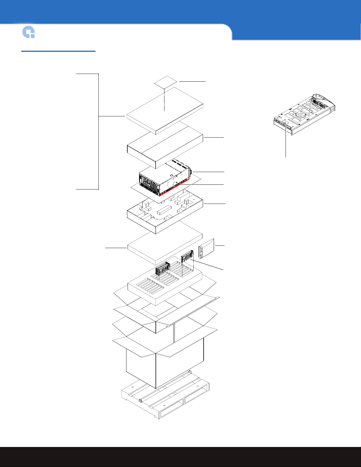
Unpacking the DXi3500/DXi5500
This section explains how to unpack both the DXi3500 and DXi5500 system components
and move them to their final installation location.
By following these instructions, you help ensure that the system will continue to be
safeguarded after it arrives at the installation site.
Unpack and remove the following components from the packing materials (see figure 2
and figure 3
Caution: Do NOT discard the packing materials after the system is unpacked. The
• DXi3500 or DXi5500 chassis
• Hard drive sleds
• Accessory kit
Warning: The DXi3500 weighs 38 lbs (17.24 kg) and the DXi5500 weights 85 lbs
):
packaging materials must be used if the system is relocated.
(38.56 kg) without hard drives. Two people are required to lift either unit.
4 Unpacking the DXi3500/DXi5500
Page 5
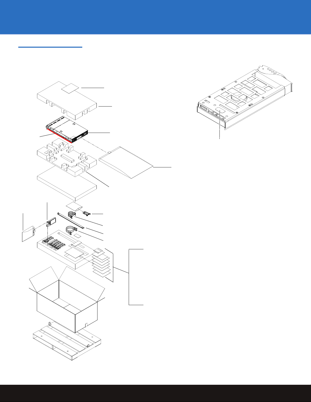
Figure 2 Unpacking the
Foam
Foam
DXi3500 chassis
Battery Backup
Unit (BBU)
Ethernet cables (2)
Hard drive
sleds
Rail kit (rails, screws, clip nuts)
Antistatic
bag
Lift point
Antistatic bag
Power cables (2)
• Documentation CD
• Serial number sheet
• StorageCare Guardian flyer
• New Customer Guide
• Drive Configuration
• China RoHS Component List
• User’s Guide Addendum
• ESD wrist strap
Hard drive
number label
Waste Electrical and Electronic
Equipment (WEEE) document
DXi3500
DXi3500 and DXi5500
Unpacking the DXi3500/DXi5500 5
Page 6
DXi3500 and DXi5500 Quick Start Guide
Corrugated cap
Foam
DXi5500 chassis
Hard drive sleds
Antistatic bag
Lift point
Accessory Kit Items:
• Documentation CD
• Serial number sheet
• StorageCare Guardian flyer
• New Customer Guide
• Drive Configuration
• China RoHS Component List
• User’s Guide Addendum
• Battery Backup Units (2)
• Registration card
• Rail kit (outer rails, screws,
clip nuts)
• Power cords (4)
• Ethernet cables (2)
• ESD wrist strap
Hard drive
number label
Foam
Waste Electrical and Electronic
Equipment (WEEE) document
Figure 3 Unpacking the
DXi5500
6 Unpacking the DXi3500/DXi5500
Page 7

Installing the DXi3500/DXi5500 System
Installing the DXi3500/5000 in a rack consists of the following steps:
• Locating the Mounting Position
• Installing the DXi3500/DXi5500 Chassis
DXi3500 and DXi5500
Locating the Mounting
Position 0
Both the DXi3500 and DXi5500 systems are designed to fit in a standard 19 inch wide rack.
It is important to the chassis installation to locate the hole pattern in the rack rails (see
figure 4
).
Installing the DXi3500/DXi5500 System 7
Page 8
DXi3500 and DXi5500 Quick Start Guide
7U of rack space
1 DXi3500 System (2U)
2U
1U = 1.75 in
(44.45mm)
1 DXi5500 System (5U)
1U = 1.75 in
(44.45mm)
5U
.625 in (15.9 mm)
.625 in (15.9 mm)
.5 in (12.7 mm)
.625 in (15.9 mm)
.625 in (15.9 mm)
Top of rack
.312 in (7.92 mm)
.5 in (12.7 mm)
Hole pattern
The marks above (X)
indicate the location of
mounting hardware on
the rack rails. Ensure that
any necessary mounting
hardware is installed on
the rack rails prior to
installing the chassis.
Figure 4 Rail Hole Pattern
Warning: If the rack is empty at the time of installation, do NOT install the DXi3500
or DXi5500 chassis too high in the rack. The weight of the chassis may
cause the rack to become “top heavy” and unstable if installed in the top of
an empty rack.
8 Installing the DXi3500/DXi5500 System
Page 9
DXi3500 and DXi5500
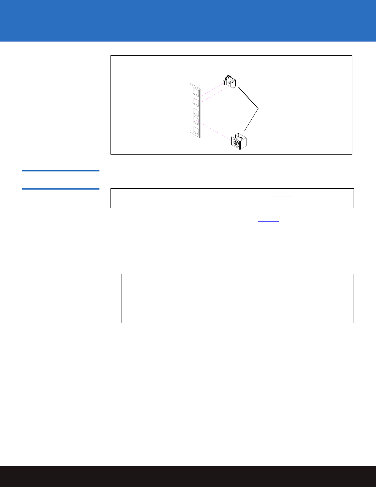
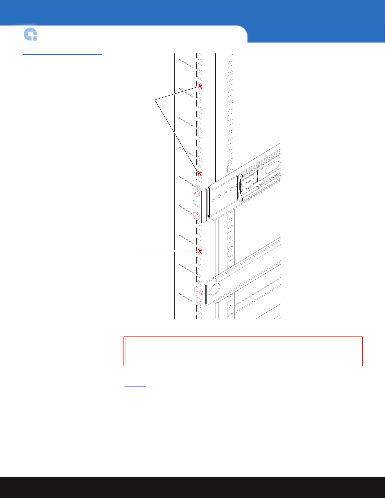
Clip nuts
Note: Quantum ships sufficient clip nuts to support mounting the DXi3500/DXi5500
rack rails and also to secure the front of the chassis to the rails.
Installing the DXi3500/ DXi5500 Chassis 0
To install the DXi3500/DXi5500 chassis:
Note: Ensure that clip nuts are installed on the rails (see figure 4
) prior to installing
the DXi5500 rails.
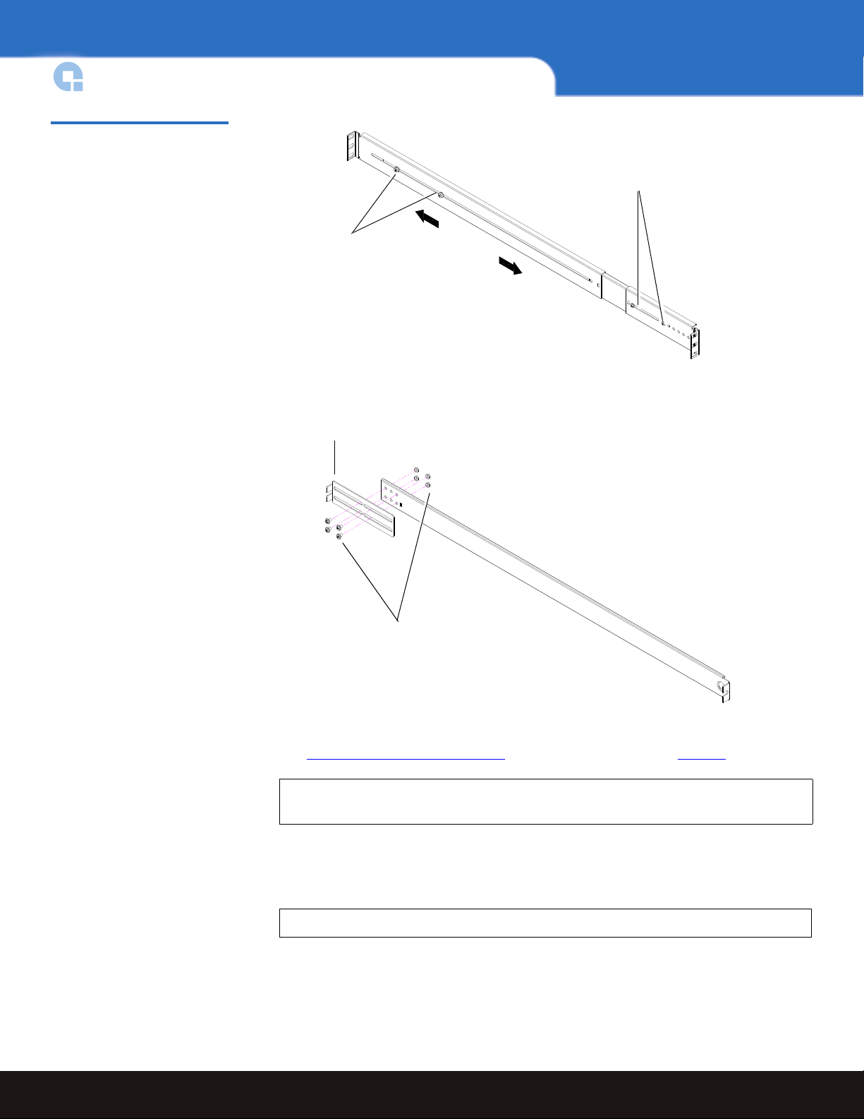
1 Assemble the DXi3500/DXi5500 support brackets figure 5
•
For the DXi5500 - The DXi5500 rails are preset for easy installation. Loosen the two
:
nuts securing the back portion of the rail so the rail can adjust to the depth of the
rack.
•
For the DXi3500 - The DXi3500 rails are preset for 28 in (71.1cm). Loosen the nuts
to adjust the rails to the depth of the rack.
Note: Two sizes of support brackets are included with the DXi3500 rails to
support various rack depths. Measure the depth of the rack to determine
the depth. The
to 31 in (71.1 to 78.7 cm). The
short brackets (5 in., 12.7cm) are used for rack depths of 28
long brackets (10 in., 25.4 cm) are used for
rack depths of 32 to 36 in (81.3 to 91.4 cm). Use the appropriate support
bracket for your rack.
Installing the DXi3500/DXi5500 System 9
Page 10
DXi3500 and DXi5500 Quick Start Guide
DXi3500: The brackets are
secured with four #8 PHILLIPS
screws and four nuts.
DXi3500: Bracket (short brackets
pre installed)
DXi5500:
Adjustment screws;
adjusts to the depth
of your rack
DXi5500: Front mounting
bracket preset. Ensure the
screws are in the correct
position.
D
X
i
5
5
0
0
r
a
c
k
r
a
i
l
s
D
X
i
3
5
0
0
r
a
c
k
r
a
i
l
s
Figure 5 Assembling the Rack
Rails
2 Install the left and right chassis support brackets at the beginning of a hole pattern
(see Locating the Mounting Position
) and secure as follows (see figure 6):
Note: The support brackets extend to accommodate rack depths of 30 to 36 in.
(76.2 to 91.4 cm).
•
DXi3500 - One 10-32 x .25 in. Slotted screw and a three hole nut plate on each rail
at the front and back of the rack. 10-32 x .25 in. PHILLIPS screws and nuts are also
provided for racks with threaded holes (M5 x 32 metric also provided).
Note: The DXi3500 support brackets must be installed on the inside rack rails.
•
DXi5500 - Two 10-32 x .50 in. PHILLIPS screws on each rail at the front and back of
the rack for the DXi5500 (M5 x 32 metric also provided).
10 Installing the DXi3500/DXi5500 System
Page 11
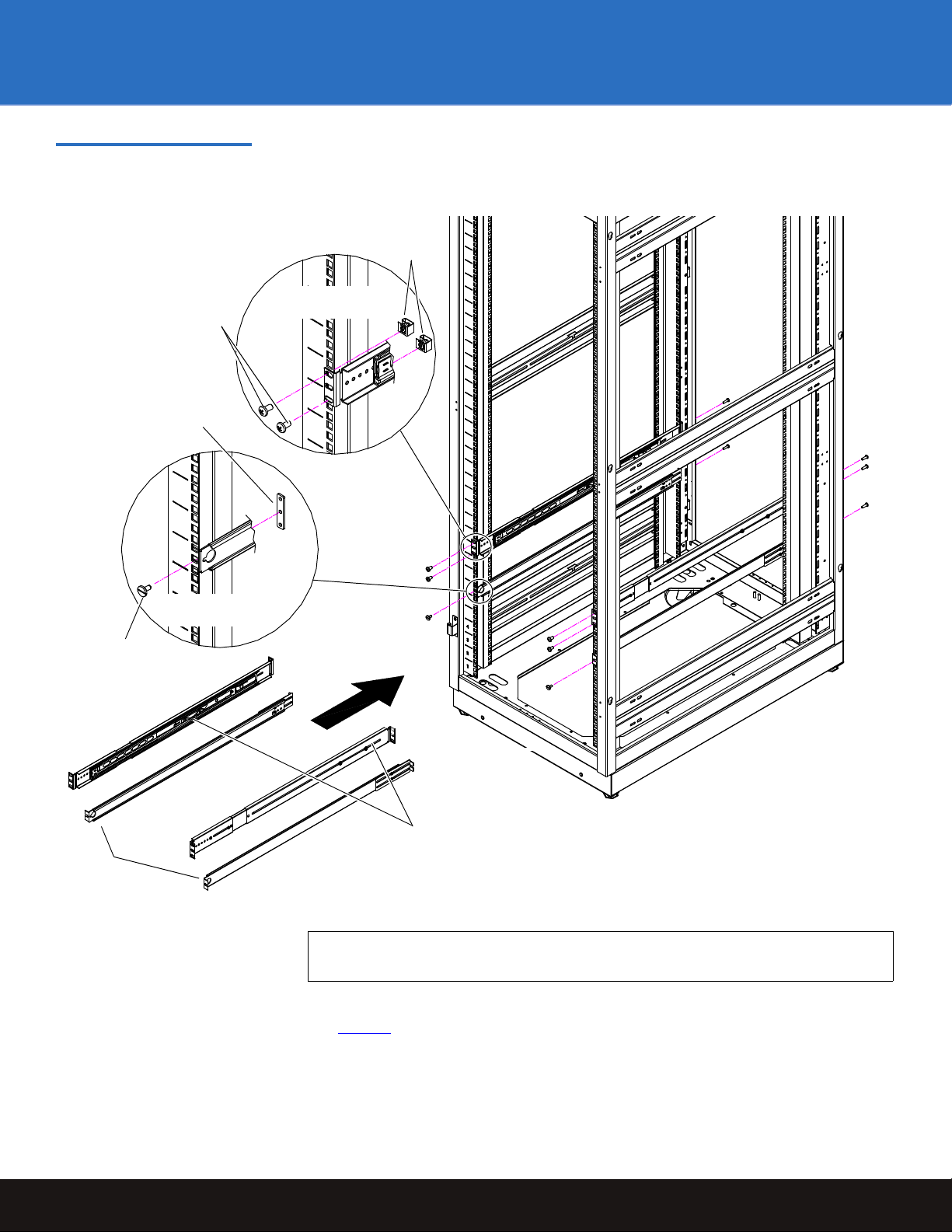
Figure 6 Installing the Chassis
DXi5500 support
brackets
DXi3500
support
brackets
10-32 x .50
PHILLIPS
screws
Clip nuts
Three hole nut plate,
use middle hole (two
types of threaded nut
plates are provided)
10-32 x .25
slotted screw
DXi5500 support
brackets
DXi3500 support
brackets
Support Brackets (DXi3500 and
DXi5500)
DXi3500 and DXi5500
3 Once the rails are secured to the rack, tighten the rail adjustment nuts on each rail.
Note: Ensure that the rails are level front to back and side to side when installed
4 With the support brackets installed, prepare the chassis mounting holes if necessary
(see figure 7
rack.
in the rack.
for hole location). These are the holes used to secure the chassis to the
Installing the DXi3500/DXi5500 System 11
Page 12
DXi3500 and DXi5500 Quick Start Guide
Chassis mounting
holes
Chassis mounting
holes
D
X
i
5
5
0
0
s
u
p
p
o
r
t
b
r
a
c
k
e
t
D
X
i
3
5
0
0
s
u
p
p
o
r
t
b
r
a
c
k
e
t
Figure 7 DXi3500/DXi5500
Chassis Mounting Holes
12 Installing the DXi3500/DXi5500 System
5 Carefully slide the chassis into the rack.
Warning: The DXi3500 weighs 38 lbs (17.24 kg) and the DXi5500 weights 85 lbs
(38.56 kg) without hard drives. Two people are required to lift either
unit.
6 Secure the DXi3500/DXi5500 chassis to the rack with the following hardware (see
figure 8
•
):
DXi3500 - two 10-32 x .5 in.black PHILLIPS screws on each side of the front of the
chassis. Tighten to 5 in/lbs.
•
DXi5500 - two 10-32 x .5 in. black PHILLIPS screws on each side of the front of the
chassis.
Page 13

Figure 8 Securing the
DXi3500 chassis
DXi5500 chassis
10-32 in. (M5) screws
Clip nut, installed
in step 4
DXi3500/DXi5500 Chassis to
the Rack
DXi3500 and DXi5500
7 Install each of the hard drive sleds into the DX-Series storage array chassis. Ensure
each drive is completely installed in the chassis with the drive handle in the closed
position (see figure 10
for DXi3500 and figure 11 for DXi5500).
Caution: Use ESD procedures when handling the hard drives sleds (see
“Taking ESD Precautions” on page 3). Place the ESD wrist strap on
your wrist and connect the other end of the strap to the DXi3500/
DXi5500 chassis.
Installing the DXi3500/DXi5500 System 13
Page 14

DXi3500 and DXi5500 Quick Start Guide
Drive 0 Drive 1 Drive 2 Drive 3
Drive 4 Drive 5 Drive 6 Drive 7
Array Controller 1
Drive 0
Array Controller 1
Drive 1
Array Controller 1
Drive 2
Array Controller 1
Drive 3
Array Controller 1
Drive 4
Array Controller 1
Drive 5
Array Controller 1
Drive 6
Array Controller 1
Drive 7
Array Controller 1
Drive 8
Array Controller 1
Drive 9
Array Controller 1
Drive 10
Array Controller 1
Drive 11
Array Controller 2
Drive 0
Array Controller 2
Drive 1
Array Controller 2
Drive 2
Array Controller 2
Drive 3
Array Controller 2
Drive 4
Array Controller 2
Drive 5
Array Controller 2
Drive 6
Array Controller 2
Drive 7
Array Controller 2
Drive 8
Array Controller 2
Drive 9
Array Controller 2
Drive 10
Array Controller 2
Drive 11
Caution: The hard drives must be installed in the proper sequence since RAID
Figure 9 Hard Drive Order
sets have already been established at the factory. Refer to the label on
the bottom of the drive sled for the drive number. The hard drive
numbering starts in the lower left-hand drive bay and then moves to
the right (see figure 9
).
14 Installing the DXi3500/DXi5500 System
Page 15

Figure 10 Installing the Disk
D
r
i
v
e
0
D
r
i
v
e
1
D
r
i
v
e
4
D
r
i
v
e
6
D
r
i
v
e
7
D
r
i
v
e
5
D
r
i
v
e
2
D
r
i
v
e
1
1
D
r
i
v
e
0
D
r
i
v
e
0
D
r
i
v
e
1
1
Array
controller 2
Array
controller 1
Drives in the DXi3500 Chassis
DXi3500 and DXi5500
Figure 11 Installing the Disk
Drives in the DXi5500 Chassis
Installing the DXi3500/DXi5500 System 15
Page 16

DXi3500 and DXi5500 Quick Start Guide
Removable BBU tray
Notch in upper left-hand
corner
8 Install the replacement BBU tray (included with the accessory kit) into the system
chassis and tighten the captive screws with a PHILLIPS screw driver (see figure 12
the DXi3500 and figure 13
Note: Ensure that the notch location on the removable BBU tray is in the correct
Figure 12 Installing the BBU
Tray (DXi3500)
for
for DXi5500).
position:
• Upper left-hand corner for the DXi3500
• Lower left-hand corner for the DXi5500
16 Installing the DXi3500/DXi5500 System
Page 17

Figure 13 Installing the BBU
Removable BBU tray
Notch in lower left-hand
corner
Tray (DXi5500)
DXi3500 and DXi5500
The DXi3500/DXi5500 chassis is now installed in the rack.
Installing the DXi3500/DXi5500 System 17
Page 18

DXi3500 and DXi5500 Quick Start Guide
Power supply cables
Ethernet ports
Fibre Channel ports (Optyon™ card)
12
FC1FC2
Cabling the DXi3500/DXi5500
The cabling instructions differ depending on the system installed. Refer to the following
sections for either the DXi3500 or DXi5500 system:
• Cabling a DXi3500 System
• Cabling a DXi5500 System
Cabling a DXi3500 System 0
Figure 14 DXi3500 System
Cabling
Connect the following cables to the back of the DXi3500 system (see figure 14):
• Connect a power cable to each power supply and to a power source
• Fibre Channel cable (optional) to Optyon card and storage area network (SAN) or
host.
Note: Do not connect the Ethernet cables to the local area network (LAN) at this
time.
Cabling a DXi5500 System 0
Connect the following cables to the back of the DXi5500 system (see figure 15):
• Connect a power cable to each power supply and to a power source
• Fibre Channel cable (optional) to Optyon card and storage area network (SAN) or
host.
Note: Do not connect the Ethernet cables to the local area network (LAN) at this
time.
18 Cabling the DXi3500/DXi5500
Page 19

Figure 15 DXi5500 System
Power supply cables
Ethernet ports Fibre Channel ports (Optyon cards)
12
Power supply cables
FC1
FC2
FC3
FC4
Cabling
DXi3500 and DXi5500
Initial Configuration
Before the DXi3500/DXi5500 is operational, you must configure the system by completing
the remote management setup screens.
Configuring the DXi3500/DXi5500 consists of the following major steps:
• Accept the License Agreement
• Complete the Network Configuration
• Complete the User Registration
• Set the Date and Time
• Create Cartridges on the DXi3500/DXi5500
Initial Configuration 19
Page 20

DXi3500 and DXi5500 Quick Start Guide
Power button
Power button
To configure the DXi3500/DXi5500:
Note: Ensure that all Fibre Channel hosts/switches or Ethernet switches are powered
on before turning on the DXi3500/DXi5500 system.
1 Turn on the DXi3500/DXi5500 system by pressing the power button located on the
front of the chassis (see figure 16
Note: Wait 10 minutes before continuing with the procedure.
Figure 16 Power Buttons
).
Note: The system BBU may take a number of hours to fully charge, during this
time the DXi3500/DXi5500 will run in a slower mode.
2 Connect an Ethernet cable to port ETH1 and to the local area network (LAN) (see
figure 14
for DXi3500 and figure 15 for DXi5500).
20 Initial Configuration
Page 21

DXi3500 and DXi5500
3 On a computer on the same subnet as the DXi3500/DXi5500, enter the IP address of
the system in the Address field of a web browser.
Figure 17 Log In Screen
Note: The default IP address is:
The
Log In screen displays (see figure 17).
10.1.1.1 for port 1 and 10.0.1.0 for port 2.
4 Select Administrator and enter password for the password.
The
License Agreement screen displays (see figure 18).
Initial Configuration 21
Page 22

DXi3500 and DXi5500 Quick Start Guide
Figure 18 License Agreement
5 Read the license agreement and press I Accept to continue.
Note: If you do not accept the license agreement, the DXi3500/DXi5500 will not
function.
The
Network Configuration screen displays (see figure 19).
22 Initial Configuration
Page 23

Figure 19 Network
Configuration
DXi3500 and DXi5500
The Network Configuration page contains links to individual Ethernet port information
as well as general network information.
6 Select the IP address type (
table 2
for IPv4 and table 3 for IPv6).
IPv4 and IPv6) and edit the information as desired (see
Note: When DHCP is disabled, the default IP address for port 1 is 10.1.1.1. with a
netmask of 255.255.255.0 The default IP address for port 2 is 10.0.1.0. with
a network mask of 255.255.0.0.
Initial Configuration 23
Page 24

DXi3500 and DXi5500 Quick Start Guide
Table 2 IPv4 Network
Configuration Fields
Field Description
IPv4 Enable
DHCP
IPv4 Address
Network Mask
Link Speed &
Duplex
Port Gateway
Enable or disable IPv4 on the specific DXi3500/DXi5500 port (Port 1 and Port 2).
Enable or disable DHCP on the specific DXi3500/DXi5500 port (Port 1 and Port 2).
Set the IPv4 address for the DXi3500/DXi5500 system.
Set the Network Mask for the DXi3500/DXi5500 system.
Set the Link Speed and Duplex for the DXi3500/DXi5500 system (10/100/half/full/auto).
The Port Gateway is a static route you can configure for this interface. It is optional. If you want to
configure a route, you must specify all three fields (
Network
Netmask
Gateway Set the Gateway for the IPv4 address for IPv4 route.
Table 3 IPv6 Network
Configuration Fields
Field Description
Network, Netmask, and Gateway).
Set the Network Address of this route. Usually, it is the subnet of the static IPv4
address.
Set the Network Mask for this route.
IPv6 Enable
Static
DHCP
Stateless
IPv6 Address
Network Mask
Current
Addresses
Enable or disable IPv6 on the specific DXi3500/DXi5500 port (Port 1 and Port 2).
Enable or disable Static on the specific DXi3500/DXi5500 port (Port 1 and Port 2).
Enable or disable DHCP on the specific DXi3500/DXi5500 port (Port 1 and Port 2).
Enable or disable Stateless on the specific DXi3500/DXi5500 port (Port 1 and Port 2).
Set the Static IP address for the DXi3500/DXi5500 system.
Set the Network Mask for the DXi3500/DXi5500 system.
View all the IPv6 addresses available to the corresponding port i.e., Static, DHCP, stateless, and link
local on the IPv6 route.
7 In the General area, select the port you wish to associate with the default gateway.
8 Set the default
IPv4 Gateway, Host, Domain information, and IPv6 Gateway
information.
24 Initial Configuration
Page 25

9 Click Apply.
DXi3500 and DXi5500
Note: In case of
IPv4 Configuration, if the system has DHCP enabled and cannot
receive an IPv4 address from the DHCP server, the system will reset back
to the default IPv4 address (
10.1.1.1 for port 1 and 10.0.1.0 for port 2). If the
port has DHCP enabled, the DHCP server provides the default gateway,
domain name, and DNS IP address even though the user has entered
values for these fields.
In case of
IPv6 Configuration, if the system has DHCP enabled and cannot
receive an IPv6 address from the DHCP server, the system will reset back
to the default IPv6 address (
2001:1:1:1 for port 1 and 2001:1:1:1 for port 2). If
the port has DHCP only enabled, the DHCP server provides the default
gateway, domain name, and DNS IP address, even though the user has
entered values for these fields.
If the network settings have been changed, the network services will restart. This may
take up to a minute to complete.
Note: Refer to the Quantum DXi3500 and DXi5500 User’s Guide (PN 81-81701) for
additional network configuration information.
The
User Registration screen displays (see figure 20).
Initial Configuration 25
Page 26

DXi3500 and DXi5500 Quick Start Guide
Figure 20 User Registration
10 The registration information is sent to Quantum to allow the system to be easily
serviced and maintained. If you do not want to register on-line, press
Skip, then fill
out and mail the warranty card included in the DXi3500/DXi5500 accessory kit. When
finished, click
The
Date and Time screen displays (see figure 21).
Register Now to continue.
26 Initial Configuration
Page 27

Figure 21 Date and Time
Configuration
DXi3500 and DXi5500
11 There are two options for setting the system date and time:
a Select
Manual to manually set the system date and time using the Edit button for
the system date and drop down boxes for the system time.
b Select
Use NTP (Network Time Protocol) to synchronize the DXi3500/DXi5500
system to an NTP server. The “Select a Server” selection makes a list of wellknown NTP servers such as the U.S. Naval Observatory Master Clocks in
Washington, DC and Colorado Springs, Colorado available. The “Specify server”
selection enables you to type the name or IP address of any desired NTP server.
NTP sends periodic time requests to the DXi3500/DXi5500 system, obtaining
time stamps and using them to adjust the system’s clock.
c Select the
d Click
Timezone.
Apply.
Note: Saving the new date and time settings may cause the login session to
expire. If necessary, log back into the system to continue the setup.
The
Cartridge Creation screen displays (see figure 22).
Initial Configuration 27
Page 28

DXi3500 and DXi5500 Quick Start Guide
Figure 22 Cartridge Creation
12 Enter the quantity of tape cartridges.
Note: The quantity should not exceed the maximum limit set for the number of
cartridges that can be created. The minimum value for the number of
cartridges is 1.
13 Enter the capacity required for each tape cartridge.
Note: The capacity should not exceed the maximum limit set for the capacity of
the cartridge. The minimum value for cartridge capacity is 5 GB.
14 Enter the starting cartridge barcode.
Note: The barcode format must be AANNNN, where A is any uppercase alpha-
numeric character and N is any single digit (0-9). Barcodes automatically
increment.
15 Click Apply.
The cartridges are created and are available on the DXi3500/DXi5500 system.The
Finish System Setup screen displays.
16 Click
OK to apply your settings.
28 Initial Configuration
Page 29

Creating a Partition
After you have initially configured your DXi system and created cartridges, you must
create a partition before backing up data to your system.
Creating a partition and a new system consists of the followings steps:
• Deleting the Default Partition
• Creating a New Partition
• Creating Device Mappings
DXi3500 and DXi5500
Deleting the Default
Partition 0
Figure 23 Logging into the
System
Every DXi3500/DXi5500 is shipped with a default partition that consists of six tape drives
and the number of tape cartridges created during the installation wizard setup. Before
you can create a new partition, you must first delete the original default partition.
To delete the default partition:
1 On a computer on the same subnet as the DXi3500/DXi5500, enter the IP address of
the system in the Address field of a web browser (see figure 23
Note: This IP address was set during the installation wizard setup (see
figure 19
).
).
2 Select Administrator from the Login Type list and enter the Administrator Password.
The default password is
The
Home screen displays (see figure 24).
password.
Creating a Partition 29
Page 30

DXi3500 and DXi5500 Quick Start Guide
Main menu
Figure 24 Home Screen
3 You must turn the system offline before you can delete the Default Partition. Click
Utilities from the Main menu to turn the system offline (see figure 25).
Figure 25 Utilities Screen
4 Click Offline to turn the system offline.
The system is offline.
5 Click
30 Creating a Partition
Configuration from the Main menu and select the VTL tab (see figure 26).
Page 31

Figure 26 VTL Tab Screen
Default partition
Delete
DXi3500 and DXi5500
6 Click the Default Partition link.
Figure 27 Default Partitioning
Screen
The
Default Partition screen displays (see figure 27).
7 Click Delete to delete the Default Partition.
You are prompted to confirm the partition deletion.
8 Click
Yes to continue.
You are prompted to confirm the tape cartridge erasure.
Creating a Partition 31
Page 32

DXi3500 and DXi5500
Partition information
Deduplication state
Available tape
cartridges
Move to selected
tape cartridges
9 Click Yes to continue.
You are warned that erasing the tape cartridges will destroy any data on the tape
cartridges.
Creating a New Partition 0
Figure 28 Add Partition Screen
10 Click
11 Click
Yes to continue.
The
Default Partition is deleted.
OK to continue.
Continue with Creating a New Partition
After the default partition has been deleted, you can now create a new partition.
To create a new partition:
1 Click
Add from the VTL tab on the Configuration screen.
The
Add Partition screen displays (see figure 28).
2 Enter the following Partition information:
a Enter the
b Select the
Partition Name.
Type of Library emulation, the default selection is Quantum DXi.
Note: Refer to your backup application documentation when choosing a library
type. Select a library presentation that is supported by your backup
application.
Creating a Partition 32
Page 33

DXi3500 and DXi5500
c Select the Type of Tape Drives, the default selection is Quantum DLT7000.
Note: Refer to your backup application documentation when choosing a tape
drive type. Select a tape drive presentation that is supported by your
backup application.
d Enter the Number of Tape Drives. The maximum number is 64.
Creating Device Mappings 0
e Enter the
f Select the
Number of Empty Bins.
Deduplication State. The default setting is Enabled. Once you have
created a partition, the deduplication setting cannot be changed.
g Select the tape cartridges from the
button to move the tape cartridges to the
3 Click
Apply to create the new partition.
Available Tape Cartridge list and click the Move
Selected Tape Cartridge list.
You are prompted to confirm the partition creation.
4 Click
Yes to continue.
The new partition is created.
5 Click
OK to continue.
Continue with Creating Device Mappings
.
After you have created the new partition, you must assign device mappings so it can be
available on the LAN or SAN network for backups.
To create device mappings:
1 Click
Hardware from the Configuration menu.
The
Device Mappings screen displays (see figure 29).
Creating a Partition 33
Page 34

Figure 29 Device Mappings
Auto Populate
Screen
DXi3500 and DXi5500
2 There are three ways to auto populate the device mappings:
a Click
Partitions Per Port to automatically assign the partition to the first available
port.
b Click
iSCSI Only to automatically assign the partition to the first available iSCSI
port.
c Click
Fibre channel Only to automatically assign the partition to the first available
Fibre Channel port.
3 You can manually assign the partition to a particular port by selecting the drop down
boxes under each port and assigning the robot and tape drives accordingly.
Caution: If you are manually assigning the robot and tape drives to your
Ethernet and Fibre Channel ports, you MUST assign the devices in
numeric order starting with L0 and continuing with L1, L2, L3 and so
forth. You MUST restart with L0 for each additional port. Do NOT
assign the devices out of order.
4 If additional LUNs are required, click
5 Click
Apply to create the device mappings.
Add LUN.
The device mappings are created.
6 Click
OK to continue.
The partition is available for backups.
7 From the
Utilities page, click Online to turn the system online.
The system is online.
Creating a Partition 34
Page 35

Creating a NAS Share
The DXi3500 and DXi5500 systems have the ability to serve as a NAS appliance for
backup purposes. The
Note: If this is a Windows NAS share, you must configure the Windows domain (see
DXi3500 and DXi5500
NAS page is used to configure the NAS portion of the system.
the Quantum DXi3500 and DXi5500 User’s Guide, PN 81-81701) prior to creating
your NAS share.
Figure 30 NAS Page
To access the
1 From the
The
NAS page displays (see figure 30).
NAS page:
Storage tab, click the NAS link.
2 Click Add to add a NAS share.
Note: To
Add NAS Share page displays (see figure 31).
The
Edit a share, click the Share Name link.
Creating a NAS Share 35
Page 36

Figure 31 Add NAS Share
Page
DXi3500 and DXi5500
3 Edit the NAS share information as desired (see table 4 for a description of the fields).
Table 4 NAS Share Fields
Note: If you are editing a share, only the Description and Enforce read-only
4 Click
access to this share
Apply.
options can be edited.
Field Description
Name
Description (optional)
Enforce Read Only
Access to this Share
Enable De-duplication
Enter a name for the NAS share.
Enter a desciption for this NAS share (optional).
Select this option to make this NAS share read only. Once
selected, you will not be able to write to this share.
Enable de-duplication to optimize disk usage. De-duplication
can only be enabled or disabled while a share is being created.
Export using CIFS
Export using NFS
Select CIFS protocol for use on a Windows network.
Select NFS protocol for use on a Linux network.
Creating a NAS Share 36
Page 37

DXi3500 and DXi5500
The DXi3500/DXi5500 is configured and ready for operation. Refer to the Quantum
DXi3500 and DXi5500 User’s Guide (PN 81-81701) for additional information on the
remote management screens. If you need to enable any licensed features such as data
replication, refer to the
Note: At the time of installation, your BBU may not be fully charged. Until the
system has completed a BBU recharge, it is possible your system
performance will be degraded. When the BBU is fully charged, the system
will return to a normal status. Recharging the BBU may take up to four
hours.
License Key section in the DXi3500 and DXi5500 User’s Guide.
Creating a NAS Share 37
Page 38

DXi3500 and DXi5500 Quick Start Guide
For assistance contact Quantum Technical Assistance center:
North America +1-800-284-5101
UK, France, and Germany 00800 4 QUANTUM
EMEA +44 1256 848 766
For worldwide support: www.quantum.com/contactsupport
Backup. Recovery. Archive. It’s What We Do.
©2008 Quantum Corporation. All rights reserved. Quantum, the Quantum logo, and all other
logos are registered trademarks of Quantum Corporation or their respective owners.
*81-81700-03*
81-81700-03 A01
Quantum Corp. (NYSE: QTM) is the leading global storage company
specializing in backup, recovery and archive. Combining focused
expertise, customer-driven innovation, and platform independence,
Quantum provides a comprehensive range of disk, tape, media, and
software solutions supported by a world-class sales and service
organization. As a long-standing and trusted partner, the company works
closely with a broad network of resellers, OEMs, and other suppliers to
meet customer’s evolving data protection needs.
81-81700-03 A01 November 2008
 Loading...