

Page 1
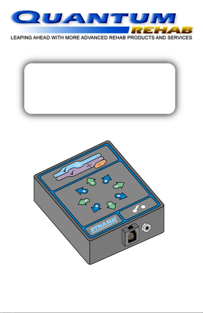
Dynamic DX
Scanner Control
M
T
Basic Operation Instructions
Page 2

2 Basic Operation Instructions DX Scanner
IMPORTANT NOTICE
This manual describes basic operation for the Dynamic DX Scanner Control
only and must be read in conjunction with the owners manual supplied with
your power chair. Please read both manuals in their entirety before operating
the Dynamic DX Scanner Control or your power chair.
This manual is intended as a supplement to the in-service training provided
by your authorized provider. If you have any questions or problems regarding
the Dynamic DX Scanner Control, please contact your authorized provider.
Copyright © 2001
Pride Mobility Products Corporation
Page 3

DX Scanner Basic Operation Instructions 3
TABLE OF CONTENTS
INTRODUCTION ................................................................................ 4
Dynamic DX Scanner Control................................................................... 4
SELECT MODE ................................................................................... 6
DRIVE MODE ....................................................................................... 6
SEAT MODE ......................................................................................... 7
ENVIRONMENTAL MODE .............................................................. 8
SCANNING SPEED ADJUSTMENT ........................................... 8
Page 4

4 Basic Operation Instructions DX Scanner
INTRODUCTION
Welcome to Quantum Rehab, a division of Pride Mobility Products
Corporation (Pride). Quantum Rehab is dedicated to the customization of
power chairs for users with advanced rehabilitation and mobility issues.
Quantum Rehab also expands possibilities for enhanced healthcare attendant
control over power chair functions to provide a secondary level of support
for our customers where necessary.
Dynamic DX Scanner Control
The Dynamic DX Scanner Control allows the power chair user to control
drive modes, actuators, and secondary remote controls.
This manual is designed to explain basic operation of the following functions
available with the Scanner:
1. Select Mode
- Allows the user to choose one of three different modesDrive, Seat, or
Environmental.
2. Drive Mode
- Allows the user to control the speed and direction of the power chair.
3. Seat Mode
- Allows the user to select and adjust one of four seat actuators.
4. Environmental Mode
- Allows the user to select and control the attached environmental control
or communication device.
5. Scanning Speed Adjustment
- The user can adjust the speed with which the Scanner cycles through
the available options.
Figure 1 provides information on the Scanner Control components and
connections. Use this diagram to familiarize yourself with the function and
location of each component before using the Dynamic DX Scanner Control.
Page 5

DX Scanner Basic Operation Instructions 5
Module Status LED
Indicates the status of the
Scanner; flashes when there
is a fault within the Scanner
(not the power chair).
Drive Mode LED
Indicates if the Drive
Mode is powered on
or off.
Seating Status LED
Indicates if actuator control
is powered on or off.
Seating Mode LED
Indicates if Seating Mode
is powered on or off.
Environmental Mode LED
Indicates if Environmental Mode
is powered on or off.
Direction LEDs
A set of 8 LEDs which
indicate drive direction
or function.
M
T
BACK OF MODULE
DXBUS Socket
Used as an interface to connect
the DX Scanner to other DX
compatible controls.
Environmental Socket
Used to connect an environmental
control or communication device
to the Scanner.
Figure 1. Scanner Control Components and Connections
Select Switch Socket
Used to connect a switch that
can control all functions of
the Scanner.
Page 6

6 Basic Operation Instructions DX Scanner
SELECT MODE
1. Press the On/Off Button on the DX compatible Master Remote used on
your power chair. The Module Status LED on the Scanner will light up,
indicating that it is in Standby Mode and ready for use.
2. Press the Select Switch once to activate the Scanner. All three Mode
LEDs will light up.
3. After power up, the Scanner will begin running through the three modes
Drive, Seat, and Environmental. Each Mode LED will light up in
sequence. To choose a mode, you must wait for its LED to light up, then
press the Select Switch.
NOTE: The Scanner will run through each Mode LED five (5) times
before returning to Standby Mode.
DRIVE MODE
1. Press the Select Switch when the Drive Mode LED is lit. Once selected,
the Scanner will cycle through the available drive directions.
2. To move in any direction, wait
until the desired Directional LED
is lit, then press and hold down
the Select Switch to move your
power chair in that direction. The
Scanner will automatically return
to the Forward Direction LED
after any power chair movement.
See figure 2.
Figure 2. Directional LEDs
NOTE: If the Select Switch is not pressed within three scanning cycles
of the Drive Mode, the Scanner will exit that mode.
Page 7

DX Scanner Basic Operation Instructions 7
SEAT MODE
1. Press the Select Switch when the Seat Mode LED is lit. Once selected,
the Scanner will cycle clockwise around the seating commands (Directional
LEDs).
2. There are four Seat Positioning
Actuators represented by two
each of the Directional LEDs.
For example, Actuator 1 is
represented by the Forward and
the Forward Right Directional
LEDs. See figure 3. To extend
Actuator 1, wait until the
Figure 3. Actuator Selections
Forward LED is lit, then press
and hold down the Select Switch. To retract Actuator 1, wait until the
Forward Right LED is lit, then press and hold down the Select Switch.
3. To operate a fifth actuator (if available), use the Environmental Mode
LED (see figure 1). Wait until the Environmental Mode LED is lit, then
press and hold down the Select Switch to extend the actuator. To retract
the actuator, press and hold down the Select Switch again. If you have
any questions regarding the use of the fifth actuator, please contact your
authorized provider.
NOTE: If the Select Switch is not pressed within three scanning cycles
of the Seat Mode, the Scanner will exit that mode.
Page 8

8 Basic Operation Instructions DX Scanner
ENVIRONMENTAL MODE
1. Press the Select Switch when the Environmental Mode LED is lit. Once
selected, the Scanner will cycle clockwise from the top (forward) LED.
See figure 2.
2. The first four LEDs are momentary selections, and the last four LEDs
are latching selections. Momentary selections will allow the Scanner to
continue its cycle immediately after the switch is released. Latching
selections will not allow the Scanner to continue its cycle until the Select
Switch has been pressed for a period of five seconds. The Scanner will
remain in the selected mode until the Select Switch is pressed for a period
of five seconds.
NOTE: If the Select Switch is not pressed within three scanning cycles
of the Environmental Mode, the Scanner will exit that mode.
SCANNING SPEED ADJUSTMENT
The Scanning Speed is indicated by the amount of time any one LED is lit
before the Scanner moves on to the next LED.
1. Press the Select Switch to power on the Scanner. Wait for the Mode
LEDs to light up.
2. When all three LEDs are lit, press the Select Switch and hold it down.
The Scanning Speed will reset itself to the amount of time you hold
down the Select Switch.
NOTE: The Scanning Speed will need to be adjusted every time the
Scanner is turned on. It cannot be permanently set.
Page 9

DX Scanner Basic Operation Instructions 9
NOTES
Page 10

10 Basic Operation Instructions DX Scanner
NOTES
Page 11

DX Scanner Basic Operation Instructions 11
NOTES
Page 12

12 Basic Operation Instructions DX Scanner
M
T
Quantum Hotline: 1-866-800-2002
INFMANU1747/A/JULY 2001
Exeter, PA
Visit the Rehab Zone at:
www.quantumrehab.com
 Loading...