

Page 1

6RIWZDUH,QWHUIDFH*XLGH6RIWZDUH,QWHUIDFH*XLGH6RIWZDUH,QWHUIDFH*XLGH
4XDQWXP';';';DQG';
4XDQWXP';';';DQG';
';6HULHV
$
Page 2

Quantum DX-Series Software Interface Guide, 81-81495-01 A01, November 2005, Made in USA.
Quantum Corporation provides this publication “as is” without warranty of any kind, either express or
implied, including but not limited to the implied warranties of merchantability or fitness for a particular
purpose. Quantum Corporation may revise this publication from time to time without notice.
COPYRIGHT STATEMENT
Copyright 2005 by Quantum Corporation. All rights reserved.
Your right to copy this manual is limited by copyright law. Making copies or adaptations without prior
written authorization of Quantum Corporation is prohibited by law and constitutes a punishable violation of
the law.
TRADEMARK STATEMENT
DLT, SDLT, DLTtape III, DLTtape IV and Super DLTtape I are all trademarks of Quantum Corporation.
Other trademarks may be mentioned herein which belong to other companies.
Page 3

Contents
Preface xxi
Chapter 1 Theory of Operation 1
Enhanced Data Protection Overview..............................................................1
SCSI-2 Implementation Philosophy ................................................................2
Medium Changer Elements.............................................................................. 2
Medium Transport Element...................................................................... 3
Storage Elements and Data Transfer ELements.....................................3
Events................................................................................................................... 5
Power Cycle................................................................................................. 5
DX-Series Unit On-Line Initialization Failure ........................................ 5
Operational Sequences......................................................................................6
Power-On ..................................................................................................... 6
On-Line Initialization................................................................................. 6
DX-Series Unit Inventory .......................................................................... 7
Off-Line ........................................................................................................8
Typical Application Enhancements ......................................................... 8
Chapter 2 Emulated Medium Changer SCSI Commands 9
Supported Operational Commands.............................................................. 11
Quantum DX-Series Software Interface Guide iii
Page 4

Initialize Element Status (07h)........................................................................13
Initialize Element Status with Range (E7h) ..................................................14
Inquiry (12h)......................................................................................................16
Inquiry Command Data Format .............................................................16
Standard Inquiry Data Format................................................................17
Supported Vital Product Data Page .......................................................20
Log Sense (4Dh)................................................................................................26
Mode Select (15h) .............................................................................................32
Mode Sense (1Ah) ............................................................................................39
Move Medium (A5h) .......................................................................................50
Position To Element (2Bh)...............................................................................52
Read Element Status (B8h)..............................................................................54
Release (17h)......................................................................................................71
Report LUNS (A0h)..........................................................................................73
Request Sense (03h)..........................................................................................75
Request Volume Element Address (B5h)......................................................79
Reserve (16h).....................................................................................................95
Rezero Unit (01h)..............................................................................................99
Send Diagnostic (1Dh) ...................................................................................100
Send Volume Tag (B6h).................................................................................102
Test Unit Ready (00h) ....................................................................................105
Chapter 3 Emulated DLT7000 SCSI Commands 107
Overview of Command and Status Processing .........................................108
SCSI Pointers............................................................................................109
Reset Sequence.........................................................................................110
Status/Error Reporting ..........................................................................113
DATA-Phase Command Components.................................................115
Unit Attention Condition.......................................................................118
Behavior at Power-On and SCSI Bus Reset.........................................118
Data Cache and Tape Write Interaction...............................................119
SCSI Command Descriptions .......................................................................120
Erase (19h) .......................................................................................................122
Inquiry (12h)....................................................................................................124
Standard Inquiry Data Page ..................................................................126
Vendor Unique Inquiry Data ................................................................129
Supported Vital Product Data Page .....................................................132
Load Unload (1Bh) .........................................................................................142
Locate (2Bh).....................................................................................................147
Log Select (4Ch)..............................................................................................149
iv Quantum DX-Series Software Interface Guide
Page 5

Log Detection Summary in LOG SELECT Command
Descriptor Block............................................................................... 152
Operation of LOG SELECT ................................................................... 152
Log Select Page Format..........................................................................153
Error Detection Summary in LOG SELECT Pages ............................157
Log Sense (4Dh).............................................................................................. 158
Error Detection Summary in LOG SENSE Command
Descriptor Block............................................................................... 161
Supported Pages Log Page (Page 00h) ................................................ 162
Read Error Counter Page (Page 03h) ................................................... 162
Last n Error Events Page (07h)..............................................................162
TapeAlert Page (2Eh) ............................................................................. 162
Read / Write Compression Page (32h)................................................ 166
Device Wellness Page (33h)................................................................... 171
Device Status Page (3Eh) ....................................................................... 171
Mode Select (6 /10) (15h / 55h) ................................................................... 172
Mode Parameter List .............................................................................. 174
READ / WRITE Error Recovery Page (01h) ....................................... 181
Disconnect/Reconnect Page (02h)........................................................ 183
Control Mode Page (0Ah)...................................................................... 185
Data Compression Page (0Fh)...............................................................188
Device Configuration Page (10h)..........................................................190
Medium Partition Page (11h)................................................................ 194
TapeAlert Page (1Ch) ............................................................................. 196
EEPROM Vendor Unique Page (3Eh).................................................. 200
Changeable Parameters within MODE SELECT................................ 200
Mode Sense (6/10) (1Ah / 5Ah) .................................................................. 202
MODE SENSE Data Headers ................................................................ 204
MODE SENSE Block Descriptor........................................................... 206
MODE SENSE Mode Pages................................................................... 209
Prevent / Allow Medium Removal (1Eh).................................................. 227
Read (08h) ....................................................................................................... 229
Read Block Limits (05h) ................................................................................ 232
Read Buffer (3Ch)........................................................................................... 234
Combined Header and Data Mode...................................................... 236
Data Mode................................................................................................237
Descriptor Mode ..................................................................................... 237
Read Position (34h)........................................................................................238
Receive Diagnostic Results (1Ch) ................................................................ 241
Release Unit (17h) .......................................................................................... 243
Media Changer Considerations............................................................ 244
Report LUNS (A0h) ....................................................................................... 245
Request Sense (03h) ....................................................................................... 247
Quantum DX-Series Software Interface Guide v
Page 6

Reserve Unit (16h)..........................................................................................254
Rewind (01h) ...................................................................................................257
Send Diagnostic (1Dh) ...................................................................................258
Space (11h).......................................................................................................265
Test Unit Ready (00h) ....................................................................................268
Verify (13h)......................................................................................................269
Write (0Ah)......................................................................................................271
Exception Conditions .............................................................................272
Write Buffer (3Bh) ..........................................................................................274
Write Combined Header and Data Mode (000b)................................275
Write Data Mode (010b) .........................................................................275
Download Microcode Mode (100b)......................................................276
Download Microcode and Save Mode (101b).....................................276
Write Filemarks (10h) ....................................................................................277
Appendix A Sense Key Values 279
Appendix B Media Changer Sense Code Values 281
Appendix C DLT7000 Sense Code Values 289
Appendix D Fibre Channel Topology 297
Fibre Channel Topology.........................................................................297
Fibre Channel Addressing.....................................................................298
Appendix E DX-Series Software Deviations 301
Media Changer SCSI Command Deviations.......................................301
DLT 7000 SCSI Command Deviations .................................................306
Glossary 313
vi Quantum DX-Series Software Interface Guide
Page 7

Index 317
Quantum DX-Series Software Interface Guide vii
Page 8

viii Quantum DX-Series Software Interface Guide
Page 9

Figures
Figure 1 Read Element Status Data General Structure......................... 57
Figure 2 Request Volume Element Address Data................................. 82
Figure 3 Fibre Channel Topologies ....................................................... 298
Quantum DX-Series Software Interface Guide ix
Page 10

Figures
x Quantum DX-Series Software Interface Guide
Page 11

Tables
Table 1 DX30 Storage Elements ...............................................................3
Table 2 DX100 Storage Elements .............................................................3
Table 3 DX3000 Storage Elements ........................................................... 4
Table 4 DX5000 Storage Elements ........................................................... 4
Table 5 SCSI-2 Terms.................................................................................9
Table 6 Supported Operational Commands ........................................ 11
Table 7 Initialize Element Status Command........................................ 13
Table 8 Initialize Element Status with Range Command................... 14
Table 9 Inquiry Command Data Format .............................................. 16
Table 10 Standard Inquiry Data............................................................... 17
Table 11 Supported Vital Product Data Page......................................... 20
Table 12 Unit Serial Number Page (Page 80h)....................................... 21
Table 13 Device Identification VPD Page 83h........................................ 22
Table 14 Identification Descriptor ...........................................................22
Table 15 Code Set....................................................................................... 23
Table 16 Association.................................................................................. 23
Table 17 Identifier Type ............................................................................ 24
Quantum DX-Series Software Interface Guide xi
Page 12

Tables
Table 18 Device Identification VPD Logical Unit..................................24
Table 19 Device Identification VPD World Wide Name ......................25
Table 20 Log Sense Command..................................................................26
Table 21 Supported Log Page...................................................................28
Table 22 Medium Changer Statistics Page..............................................28
Table 23 Log Parameter.............................................................................29
Table 24 Supported Log Parameter Codes for 30h Page ......................30
Table 25 Mode Select Command..............................................................32
Table 26 Mode Select Data - Vendor Unique Page 20h.........................33
Table 27 Mode Select Data - Vendor Unique Page 00h.........................34
Table 28 Mode Select Data - Element Address Assign. Page...............35
Table 29 Changeable Parameters within MODE SELECT....................37
Table 30 Mode Sense Command..............................................................40
Table 31 Mode Sense Data Header ..........................................................41
Table 32 Mode Sense Data - Vendor Unique Page 00h.........................42
Table 33 Mode Sense Data - Element Address Assign. Page...............43
Table 34 Mode Sense Data - Trans. Geometry Para. Page....................46
Table 35 Mode Sense Data - Device Capabilities Data..........................47
Table 36 Mode Sense Data - Vendor Unique Page 20h.........................48
Table 37 Move Medium Command.........................................................50
Table 38 Position To Element Command................................................52
Table 39 Read Element Status Command...............................................54
Table 40 Read Element Status Data .........................................................58
Table 41 Element Status Page ...................................................................59
Table 42 Medium Transport Element Descriptor ..................................60
Table 43 Primary Volume Tag Information............................................62
Table 44 Storage Element Descriptor.......................................................62
Table 45 Import/Export Element Descriptor.........................................64
Table 46 Data Transfer Element Descriptor............................................67
xii Quantum DX-Series Software Interface Guide
Page 13

Tables
Table 47 Alternate Volume Tag Information ......................................... 69
Table 48 Release Command...................................................................... 71
Table 49 Report LUNS Command........................................................... 73
Table 50 LUN Reporting Parameter List ................................................74
Table 51 Request Sense Command.......................................................... 75
Table 52 Request Sense Data .................................................................... 76
Table 53 Request Volume Element Address Command ...................... 79
Table 54 Volume Element Address Header ........................................... 83
Table 55 Element Status Page................................................................... 84
Table 56 Medium Transport Element Descriptor.................................. 85
Table 57 Primary Volume Tag Information ........................................... 87
Table 58 Alternate Volume Tag Information ......................................... 87
Table 59 Storage Element Descriptor ...................................................... 87
Table 60 Import/Export Element Descriptor......................................... 90
Table 61 Data Transfer Element Descriptor ........................................... 92
Table 62 Reserve Command.....................................................................96
Table 63 Element List Descriptor............................................................. 97
Table 64 Rezero Unit Command.............................................................. 99
Table 65 Send Diagnostic Command .................................................... 100
Table 66 Selftest Bit Definition............................................................... 101
Table 67 Send Volume Tag Command ................................................. 102
Table 68 Send Volume Tag Parameters ................................................ 103
Table 69 Test Unit Ready Command .................................................... 105
Table 70 Supported SCSI Commands...................................................108
Table 71 Command Descriptor Block Fields........................................ 110
Table 72 Command Descriptor Block - Field Descriptions................ 111
Table 73 Command Descriptor Block Control Field - Data Format . 112
Table 74 Command Descriptor Block Control Field -
Field Descriptions.....................................................................113
Quantum DX-Series Software Interface Guide xiii
Page 14

Tables
Table 75 Status Codes ..............................................................................114
Table 76 DATA-Phase Command Contents.........................................116
Table 77 ERASE COMMAND Descriptor Block - Data Format ........122
Table 78 INQUIRY Command Descriptor Block - Data Format........124
Table 79 INQUIRY Command Descriptor Block -
Field Descriptions .....................................................................125
Table 80 Vital Product Data - Page Codes............................................126
Table 81 Inquiry Command (12h)..........................................................126
Table 82 Standard Inquiry Data Page - Field Descriptions ................127
Table 83 INQUIRY Vendor Unique Bytes Definitions........................129
Table 84 Vendor Unique Inquiry Data Page - Field Descriptions.....131
Table 85 Supported Vital Product Data Pages Page - Data Format ..133
Table 86 Unit Serial Number Page (80h) - Data Format .....................133
Table 87 Unit Serial Number Page - Field Descriptions ....................134
Table 88 Device Identification VPD Page 83h......................................134
Table 89 Identification Descriptor..........................................................135
Table 90 Code Set......................................................................................135
Table 91 Association.................................................................................136
Table 92 Identifier Type...........................................................................136
Table 93 Device Identification VPD Logical Unit................................137
Table 94 Device Identification VPD World Wide Name ....................137
Table 95 Firmware Build Information Page (C0h) - Data Format.....138
Table 96 Firmware Build Information Page (C0h) -
Field Descriptions .....................................................................138
Table 97 Subsystem Components Revision Page (C1h) -
Data Format ...............................................................................138
Table 98 Subsystem Components Revision Page -
Field Descriptions .....................................................................140
Table 99 LOAD UNLOAD Command Descriptor Block -
Data Format ...............................................................................144
xiv Quantum DX-Series Software Interface Guide
Page 15

Tables
Table 100 LOAD UNLOAD Command Descriptor Block -
Field Descriptions.....................................................................144
Table 101 LOCATE Command Descriptor Block - Data Format......... 147
Table 102 LOCATE Command Descriptor Block -
Field Descriptions.....................................................................148
Table 103 LOG SELECT Command Descriptor Block - Data Format. 149
Table 104 LOG SELECT Command Descriptor Block -
Field Descriptions.....................................................................150
Table 105 LOG SELECT Log Page Header Format............................... 153
Table 106 LOG SELECT Log Page Header Field Descriptions............ 153
Table 107 LOG SELECT Log Parameters Format..................................154
Table 108 LOG SELECT Log Parameters Field Descriptions .............. 154
Table 109 LOG SENSE Command Descriptor Block - Data Format ... 158
Table 110 LOG SENSE Command Descriptor Block -
Field Descriptions.....................................................................159
Table 111 LOG SENSE Command Descriptor Block ............................ 160
Table 112 Supported Pages Page - Data Format.................................... 162
Table 113 TapeAlert LOG SENSE Header Format................................ 163
Table 114 TapeAlert LOG SENSE Header Field Descriptions............. 163
Table 115 TapeAlert Page Log Parameters Format...............................164
Table 116 TapeAlert Page Log Parameter Field Descriptions ............. 164
Table 117 TapeAlert Flags, Severity Levels, and Meanings................. 165
Table 118 Read / Write Compression Ratio LOG SENSE Header
Format........................................................................................ 166
Table 119 Read / Write Compression Ratio LOG SENSE Header
Field Descriptions.....................................................................167
Table 120 Log Parameters Format for Read / Write Compression Ratio
LOG SENSE Page (Parameter Codes 00h and 01h)............. 167
Table 121 Log Parameters for Read / Write Compression Ratio LOG
SENSE Page Field Descriptions (Parameter Codes 00h
and 01h) .....................................................................................168
Quantum DX-Series Software Interface Guide xv
Page 16

Tables
Table 122 Log Parameters Format for Read / Write Compression Ratio
LOG SENSE Page (Parameter Codes 02h through 09h)......169
Table 123 Log Parameters for Read / Write Compression Ratio LOG
SENSE Page Field Descriptions (Parameter Codes 02h
through 09h) ..............................................................................170
Table 124 Mode Select (6) Command Descriptor Block -
Data Format ...............................................................................173
Table 125 Mode Select (10) Command Descriptor Block -
Data Format ...............................................................................173
Table 126 MODE SELECT (6)/(10) Command Descriptor Block -
Field Descriptions .....................................................................174
Table 127 MODE SELECT (6) Mode Parameter List - Data Format....174
Table 128 MODE SELECT (10) Mode Parameter List - Data Format..174
Table 129 MODE SELECT Mode Parameter List -
Field Descriptions .....................................................................175
Table 130 MODE SELECT (6) Mode Parameter Header -
Data Format ...............................................................................175
Table 131 MODE SELECT (10) Mode Parameter Header -
Data Format ...............................................................................176
Table 132 MODE SELECT Mode Parameter Header -
Field Descriptions .....................................................................177
Table 133 MODE SELECT Mode Parameter Block Descriptor -
Data Format ...............................................................................178
Table 134 MODE SELECT Mode Parameter Block Descriptor -
Field Descriptions .....................................................................178
Table 135 MODE SELECT Page Descriptor - Data Format ..................180
Table 136 MODE SELECT Page Descriptor - Field Descriptions ........ 181
Table 137 Error Recovery Page - Data Format .......................................181
Table 138 Error Recovery Page - Field Descriptions .............................182
Table 139 Disconnect / Reconnect Page - Data Format........................183
Table 140 Disconnect / Reconnect Page - Field Descriptions ..............184
Table 141 Control Mode Page Format Descriptor - Data Format........186
Table 142 Control Mode Page Descriptor - Field Descriptions............186
xvi Quantum DX-Series Software Interface Guide
Page 17

Tables
Table 143 Data Compression Page Format Descriptor - Data Format188
Table 144 Data Compression Page Descriptor - Field Descriptions... 189
Table 145 Device Configuration Page - Data Format............................190
Table 146 Device Configuration Page - Field Descriptions..................192
Table 147 Medium Partition Page Format Descriptor - Data Format. 195
Table 148 Medium Partition Page Descriptor - Field Descriptions .... 195
Table 149 TapeAlert Page Format Descriptor - Data Format ..............196
Table 150 TapeAlert Page Format Descriptor - Field Descriptions .... 197
Table 151 Changeable Parameters within MODE SELECT .................200
Table 152 MODE SENSE (6) Command Descriptor Block -
Data Format...............................................................................202
Table 153 MODE SENSE (10) Command Descriptor Block -
Data Format...............................................................................203
Table 154 MODE SENSE Control Descriptor Block -
Field Descriptions.....................................................................203
Table 155 MODE SENSE (6) Data Header - Data Format ....................204
Table 156 MODE SENSE (10) Data Header - Data Format .................. 205
Table 157 MODE SENSE Data Header - Field Descriptions................ 205
Table 158 MODE SENSE Block Descriptor - Data Format................... 206
Table 159 MODE SENSE Block Descriptor - Field Descriptions......... 207
Table 160 MODE SENSE Page Descriptor - Data Format .................... 209
Table 161 MODE SENSE Page Descriptor - Field Descriptions .......... 210
Table 162 Read / Write Error Recovery Page - Data Format .............. 211
Table 163 Read / Write Error Recovery Page - Field Descriptions ....212
Table 164 Disconnect / Reconnect Page - Data Format........................ 213
Table 165 Disconnect / Reconnect Page - Field Descriptions.............. 214
Table 166 Control Mode Page - Data Format......................................... 215
Table 167 Control Mode Page - Field Descriptions............................... 216
Table 168 Data Compression Page - Data Format................................. 217
Table 169 Data Compression Page - Field Descriptions....................... 217
Quantum DX-Series Software Interface Guide xvii
Page 18

Tables
Table 170 Device Configuration Page - Data Format............................219
Table 171 Device Configuration Page - Field Descriptions..................220
Table 172 Medium Partition Page - Data Format ..................................222
Table 173 Medium Partition Page - Field Descriptions ........................223
Table 174 TapeAlert Page Format Descriptor - Data Format...............224
Table 175 TapeAlert Page Format Descriptor - Field Descriptions.....224
Table 176 PREVENT / ALLOW MEDIUM REMOVAL Command
Descriptor Block - Data Format ..............................................227
Table 177 PREVENT / ALLOW MEDIUM REMOVAL Command
Descriptor Block - Field Descriptions ....................................228
Table 178 READ Command Descriptor Block - Data Format..............229
Table 179 READ Command Descriptor Block - Field Descriptions....230
Table 180 READ BLOCK LIMITS Command Descriptor Block -
Data Format ...............................................................................232
Table 181 READ BLOCK LIMITS Data - Data Format..........................232
Table 182 READ BLOCK LIMITS Data - Field Descriptions................233
Table 183 READ BUFFER Command Descriptor Block -
Data Format ...............................................................................234
Table 184 READ BUFFER Command Descriptor Block -
Field Descriptions .....................................................................235
Table 185 READ BUFFER Header - Data Format. .................................236
Table 186 READ BUFFER Header - Field Descriptions ........................237
Table 187 READ BUFFER Descriptor - Data Format.............................237
Table 188 READ POSITION Command Descriptor Block -
Data Format ...............................................................................238
Table 189 READ POSITION Command Descriptor Block -
Field Descriptions .....................................................................238
Table 190 READ POSITION - Data Format ............................................239
Table 191 READ POSITION Data - Field Descriptions.........................240
Table 192 RECEIVE DIAGNOSTIC RESULTS Command Descriptor
Block - Data Format..................................................................241
xviii Quantum DX-Series Software Interface Guide
Page 19

Tables
Table 193 RECEIVE DIAGNOSTIC RESULTS Command Data -
Field Descriptions.....................................................................241
Table 194 RECEIVE DIAGNOSTIC RESULTS - Data Format............. 242
Table 195 RELEASE UNIT Command Descriptor Block -
Data Format...............................................................................243
Table 196 RELEASE UNIT Command Data - Field Descriptions ....... 243
Table 197 Report Luns Command ........................................................... 245
Table 198 LUN Reporting Parameter List .............................................. 246
Table 199 REQUEST SENSE Command Descriptor Block -
Data Format...............................................................................247
Table 200 REQUEST SENSE Command Data - Field Descriptions .... 247
Table 201 REQUEST SENSE - Data Format............................................ 248
Table 202 REQUEST SENSE Data - Field Descriptions........................ 249
Table 203 Supported Sense Keys ............................................................ 252
Table 204 RESERVE UNIT Command Descriptor Block -
Data Format...............................................................................254
Table 205 RESERVE UNIT Command Data - Field Descriptions ....... 254
Table 206 REWIND Command Descriptor Block - Data Format........ 257
Table 207 REWIND Command Data - Field Descriptions ................... 257
Table 208 SEND DIAGNOSTIC Command Descriptor Block -
Data Format...............................................................................258
Table 209 SEND DIAGNOSTIC Command Data -
Field Descriptions.....................................................................258
Table 210 SEND DIAGNOSTIC CDB Bits Selftst, DevOfl,
and UnitOfl................................................................................ 260
Table 211 SEND DIAGNOSTIC Parameter List - Data Format........... 261
Table 212 SEND DIAGNOSTIC Parameter List -
Field Descriptions.....................................................................262
Table 213 Sense Keys Used for SEND DIAGNOSTIC .......................... 264
Table 214 ASC / ASCQ for SEND DIAGNOSTIC ................................264
Table 215 SPACE Command Descriptor Block - Data Format............ 265
Table 216 SPACE Command Data - Field Descriptions ....................... 266
Quantum DX-Series Software Interface Guide xix
Page 20

Tables
Table 217 TEST UNIT READY Command Descriptor Block -
Data Format ...............................................................................268
Table 218 VERIFY Command Descriptor Block - Data Format ...........269
Table 219 VERIFY Command Data - Field Descriptions ......................269
Table 220 WRITE Command Descriptor Block - Data Format ............271
Table 221 WRITE Command Data - Field Descriptions........................272
Table 222 WRITE BUFFER Command Descriptor Block -
Data Format ...............................................................................274
Table 223 WRITE BUFFER Command Data - Field Descriptions .......275
Table 224 WRITE FILEMARKS Command Descriptor Block -
Data Format ...............................................................................277
Table 225 WRITE FILEMARKS Command Data - Field Descriptions277
Table 226 Sense Data Values (Hexadecimal)..........................................279
Table 227 Sense Data Values (Hexadecimal ...........................................282
Table 228 DLT7000 Tape Drive Sense Data Values (Hexadecimal)....290
xx Quantum DX-Series Software Interface Guide
Page 21

Preface
This guide describes the procedures and issues involved in the
development of hierarchical mass storage software applications and
utilities to communicate with the Quantum DX-Series enhanced data
protection system and this includes the following models:
•DX30
•DX100
•DX3000
•DX5000
Audience This guide is designed for use by software engineers who have a basic
understanding of SCSI principles and technology.
Purpose This document provides information about DX-Series software including:
• Theory of operation
• Software interfaces for both the DX-Series system and the virtual
DLT7000 tape drives
• Sense data values
Quantum DX-Series Software Interface Guide xxi
Page 22

Preface
Document
Organization
This guide is organized as follows:
• Chapter 1, “Theory of Operation,” explains medium changer
elements, events, operational sequences, configuration, error
recovery, system performance, and diagnostic support issues.
• Chapter 2, “Emulated Software Interfaces,” describes SCSI-2
terminology in relation to the DX-Series enhanced data protection
system. This includes required and optional SCSI-2 messages, and
operational commands.
• Chapter 3, “Emulated DLT7000 SCSI Commands,” describes SCSI
terminology in relation to the DLT7000 tape drive. This includes
required and optional SCSI-2 messages, and operational commands.
• Appendix A, Sense Key Values provides information on the
supported sense keys for request sense.
• Appendix B, Media Changer Sense Code Values provides sense code
values for the medium changer.
• Appendix C, DLT7000 Sense Code Values provides sense code values
for the DLT7000 tape drive.
• Appendix D, Fibre Channel Topology provides an overview of Fibre
Channel topology available with the DX30 and DX100 and as an
option with DX3000 and DX5000.
• Appendix E, DX-Series Software Deviations provides an overview of
the implemented changes to the DX-Series software.
• This guide concludes with a glossary and an index.
xxii Quantum DX-Series Software Interface Guide
Page 23

Preface
Notational
Conventions
This manual uses the following conventions:
0
Caution: Cautions indicate potential hazards to equipment and are
included to prevent damage to equipment. Cautions may
advise you that failure to take or avoid an action could
result in corrupt data or loss of data.
Note: Notes emphasize important information related to the main
topic.
Warning: Warnings indicate potential hazards to personal safety
and are included to prevent injury.
Tech Tip: Tech tips indicate an area that deviates from normal DLT
tape drive or changer behavior.
This manual uses the following:
• All binary numbers are succeeded by “b”
• All hexadecimal numbers are succeeded by “h”
• Error or attention conditions are represented in parenthesis that
translate as follows:
(SK=S ASC=AA ASCQ=QQ)
where:
S = hexadecimal sense key value
AA = hexadecimal additional sense code
QQ = hexadecimal additional sense code qualifier
Quantum DX-Series Software Interface Guide xxiii
Page 24

Preface
Related
Documents
Manuals associated with DX-Series system:
Document
Number Title Description
6513501 DX30/DX100 User’s
Guide
Contains sections on
installation, operation, and
diagnostic software.
6513503 DX30/DX100 Field
Service Manual
Provides removal and
replacement instructions for
all field replaceable units.
81-81493 DX3000/DX5000
User’s Guide
Contains sections on
installation, operation, and
diagnostic software.
SCSI-2 Specification 0
The SCSI-2 communications specification is the proposed American
National Standard for information systems, dated March 9, 1990. Copies
may be obtained from:
Global Engineering Documents
15 Inverness Way, East
Englewood, CO 80112
(800) 854-7179 or (303) 397-2740
Contacts Quantum Corporation company contacts are listed below.
Quantum Documentation 0
To order documentation on the DX-Series system or other products
contact:
Quantum
P. O. Box 57100
Irvine, CA 92619-7100
(949) 856-7800
(800) 284-5101
xxiv Quantum DX-Series Software Interface Guide
Page 25

Preface
Technical Publications 0
To comment on existing documentation send e-mail to:
doc-comments@quantum.com
Visit the Quantum home p age at: 0
http://www.quantum.com
Customer Support 0
The Quantum Customer Support Department provides a 24-hour help
desk that can be reached at:
North/South America: (949) 725-2100 or
(800) 284-5101
Asia/Pacific Rim: (International Code)
+61 7 3839 0988
Europe/Middle East/Africa: (International Code)
+44 (0) 1256 848748
Send faxes for the Customer Support Department to:
North/South America: (949) 725-2176
Asia/Pacific Rim: (International Code)
+61 7 3839 0955
Europe/Middle East/Africa: (International Code)
+44 (0) 1256 848777
Send e-mail for the Customer Support Department to:
North/South America: helpdesk@quantum.com
Asia/Pacific Rim: apachelp@quantum.com
Europe/Middle East/Africa: ukhelpdesk@quantum.com
Quantum DX-Series Software Interface Guide xxv
Page 26

Preface
xxvi Quantum DX-Series Software Interface Guide
Page 27

1Theory of Operation
This chapter discusses these topics:
• SCSI-2 Implementation Philosophy
• Medium Changer Elements
• Events
• Operational Sequences
Chapter 1
Enhanced Data Protection Overview 1
The Quantum DX-Series system takes advantage of high speed
hard drives to greatly reduce the time required for backup/restore
functions and also improve confidence in completing the backup
in the time allowed.
Quantum DX-Series Software Interface Guide 1
Page 28

Chapter 1 Theory of Operation
SCSI-2 Implementation Philosophy
SCSI-2 Implementation Philosophy 1
Using the SCSI-2 standard, the DX-Series system is designed so that the
host can adapt to changes in the configuration. For example, the host can
detect a change in the number of virtual tape drives configured in the DXSeries system.
The DX-Series system uses the SCSI-2 medium changer command set.
This command set is complete and includes all primitive (elemental)
commands required by a host to carry out any required complex
operation.
The DX-Series system relies on the host computer to perform complex
operations by issuing a sequence of elemental commands in the correct
order. The DX-Series system does not execute operations that could result
in damage to the device.
Medium Changer Elements 1
The medium changer command set accesses address space for the set of
physical locations and mechanisms within the DX-Series system. This
guide uses the SCSI-2 term element to refer to one member of the DXSeries system address space.
Each element is a discrete physical entity that can hold a single tape
cartridge and is represented by a unique 16-bit element address.
The DX-Series system consists of these medium changer elements:
• Medium transport element
• Storage elements
• Data transfer elements
Issue the Mode Sense command to determine:
• DX-Series system configuration
•First address
• Number of elements of each type (medium transport, storage, or data
transfer)
2 Quantum DX-Series Software Interface Guide
Page 29

Chapter 1 Theory of Operation
Medium Changer Elements
Medium Transport
Element
Storage Elements
and Data Transfer
ELements
Table 1 DX30
Storage Elements
The medium transport element consists of the following component:
1
• Virtual gripper
This mechanism can hold a single cartridge and is considered to be a
single medium transport element. It moves media between elements
within the DX-Series system.
The DX-Series system emulation is described in the following tables:
• DX30 Storage Elements
1
• DX100 Storage Elements
• DX3000 Storage Elements
• DX5000 Storage Elements
DX30 Storage Elements
Virtual tape drives 2 to 30
Virtual tape cartridges 2 to 160 per array (250GB drives),
320 per array(400 GB drives)
Table 2 DX100
Storage Elements
Number of arrays 1 to 4
Total number of virtual cartridges 640 (250GB drives), 1280 (400GB
drives)
DX100 Storage Elements
Virtual tape drives 2 to 55
Virtual tape cartridges 2 to 320 per array (250GB drives),
640 per array (400GB drives)
Quantum DX-Series Software Interface Guide 3
Page 30

Chapter 1 Theory of Operation
Medium Changer Elements
DX100 Storage Elements
Number of arrays 1 to 16
Total number of virtual cartridges 2560 (250GB drives), 5120 (400GB
drives)
Table 3 DX3000
Storage Elements
Table 4 DX5000
Storage Elements
DX3000 Storage Elements
Virtual tape drives 1 to 32
Virtual tape cartridges 1 to 80 per LUN
Number of RAID Sets 1 to 2
Total number of virtual cartridges 1 to 400 per LUN (800 max)
DX5000 Storage Elements
Virtual tape drives 1 to 64
Virtual tape cartridges 1 to 80 per LUN
Number of RAID Sets 1 to 4
Total number of virtual cartridges 1 to 400 per LUN (1600 max)
4 Quantum DX-Series Software Interface Guide
Page 31

Chapter 1 Theory of Operation
Events
Events 1
Events are system conditions created by failures or operator actions, such
as changing the DX-Series system state to offline. Some events appear as
states on the control panel.
Events are recorded in sense data. Depending on the interface, the host
can obtain the sense data either in response to a Request Sense
command or as an unsolicited message.
The DX-Series system does not support asynchronous event notification.
This simplifies the host/DX-Series interface and is acceptable because
events happen infrequently and do not require an immediate host
response.
DX-Series system events are queued. To check for DX-Series system
events, the SCSI host can issue a Request Sense command to the device.
This command causes the DX-Series system to return event sense data.
The host can issue a Request Sense command repeatedly to obtain
sense data for each queued event.
Power Cycle 1
DX-Series Unit OnLine Initialization
Failure
The most significant events are detailed in this section:
• Power Cycle
• DX-Series Unit On-Line Initialization Failure
When the DX-Series system is powered on, it generates a Power On/
Reset Occurred event (SK=6 ASC=29 ASCQ=00).
When a DX-Series system is placed on-line and initialization fails, the DXSeries system generates an event for the error condition that caused the
failure.
1
Quantum DX-Series Software Interface Guide 5
Page 32

Chapter 1 Theory of Operation
Operational Sequences
Operational Sequences 1
Operational sequences are listed in order of precedence. These
operational sequences are detailed in this section:
•Power On
• System Stopped
• On-Line Initialization
• DX-Series System Unit Inventory
• Off-Line
Power-On 1
On-Line
Initialization
When the DX-Series system is powered-on it goes through an
initialization sequence, during which:
• System goes through power sequencing and intitialization
• DX-Series system responds to these commands:
• Inquiry
• Request Sense
•Log Sense
• Mode Sense
• All other commands return a Logical Unit is Not Ready check
condition (SK=2 ASC=04 ASCQ=00)
When the power-on initialization is complete:
1 DX-Series system generates a Power On/Reset Occurred event
(SK=6 ASC=29 ASCQ=00).
2 System performs additional operational sequences, depending on the
condition of the system.
To start the on-line initialization sequence:
1
1 Power on the DX-Series system.
During the on-line initialization sequence:
6 Quantum DX-Series Software Interface Guide
Page 33

Chapter 1 Theory of Operation
Operational Sequences
• Browser indicates that the DX-Series system is performing the on-line
initialization sequence
• DX-Series system responds to these commands:
• Inquiry
• Request Sense
•Log Sense
• Mode Sense
• All other commands return a Logical Unit is Not Ready check
condition (SK=2 ASC=04 ASCQ=00)
• DX-Series system performs an inventory of its elements
• When initialization completes, the web based GUI changes to
System On-Line and the DX-Series system is fully operational
DX-Series Unit
Inventory
The DX-Series system inventories its storage elements after power up,
upon receipt of an Initialize Element Status command, or after the door
1
is closed and the DX-Series system is placed on-line.
• The local controller for the DX-Series system checks the state of the
medium transport element (gripper)
• If there is a virtual tape cartridge in the medium transport element,
the inventory cannot be performed
• If this is the case and the inventory was requested by the host,
then a check condition is set, and Transfer Full (SK=5 ASC=80
ASCQ=01) sense data is sent
• If the inventory was not requested by the host, the DX-Series
system generates a Transfer Full (SK=5 ASC=80 ASCQ=01) on-
line initialization failure event
• Each element of the DX-Series system is inventoried if it is the first
inventory made since power-on or issuing an Initialize Element
Status command
• An inventory is attempted for each virtual tape drive present
• The results of the inventory are returned with the Read Element
Status command.
Quantum DX-Series Software Interface Guide 7
Page 34

Chapter 1 Theory of Operation
Operational Sequences
Off-Line 1
Changing the DX-Series system status to Off-line through the web GUI
causes the DX-Series system to go off-line. When a DX-Series system is
placed off-line, this sequence is performed:
1 The local controller for the DX-Series system completes any currently
processing command.
2 When all commands are complete, the web GUI displays System
Off-Line.
3 The DX-Series system generates a Unit Standby Button Was
Pressed event (SK=6 ASC=80 ASCQ=09).
When the DX-Series system is off-line it responds to these commands:
• Inquiry
• Request Sense
•Log Sense
•Mode Sense
• Check condition is set for all other commands and Unit Is Turned
Off-Line (SK=2 ASC=80 ASCQ=09) is set in the sense data
The DX-Series system remains off-line until one of the other operational
sequences occur.
Typical
Application
Enhancements
For optimum system performance, please note:
• Direct the host to check for any attention or error conditions the tape
1
DX-Series system may have buffered by issuing Request Sense
commands until “no sense data available” exists.
• The internal software does not support command queueing. It is up
to the host application to queue commands to the unit. It may be
advantageous for the application to group queued commands to
require the least amount of actuator motion.
8 Quantum DX-Series Software Interface Guide
Page 35
Chapter 2
2Emulated Medium Changer
SCSI Commands
This chapter describes the specific Small Computer Systems Interface
(SCSI-2) terminology in relation to the DX-Series system.
SCSI-2 terms and their equivalent DX-Series terms.
Table 5 lists the
Table 5 SCSI-2
Terms
SCSI-2 Term Equivalent DX-Series Term
Logical Unit DX-Series system
Initiator Host computer
Data Transfer Element Virtual tape drive
Medium Transport Element Virtual gripper mechanism
Storage Element Storage bin
DX-Series system:
• Is a SCSI-2 medium changer devices - the host computer serves as the
SCSI initiator and issues commands to the DX-Series system and tape
drives, which act as SCSI targets
• SCSI target support - does not perform any initiator functions (each
DX-Series system has its own SCSI address separate from any other
SCSI devices, including the tape drives)
Quantum DX-Series Software Interface Guide 9
Page 36

Chapter 2 Emulated Medium Changer SCSI Commands
• Support asynchronous SCSI
• Is intended for use with:
• iSCSI 10, 100, 1000Mbit/sec. initiators for DX3000 and DX5000
• Fully support RFC 3720 with error handling level 0
• 1 or 2 Gb/s initiators for Fibre Channel initiators for DX30 and
DX100 (optional on DX3000 and DX5000)
• Does not support:
• SCSI queuing or linked commands - all element addresses must
be specified absolutely; no relative addressing is permitted
• Change Definition command
• Asynchronous event notification
• Extended contingent allegiance
• Overlapped command support - if this command is received
from the same host, the DX-Series system aborts the previous
command and returns a check condition with Overlapped
Commands Attempted sense data code (SK=5 ASC=54
ASCQ=00)
10 Quantum DX-Series Software Interface Guide
Page 37

Chapter 2 Emulated Medium Changer SCSI Commands
Supported Operational Commands
Supported Operational Commands 2
The DX-Series system supports all commands that the SCSI-2
specification indicates are required by all devices.
Table 6 Supported
Operational
Commands
Command Name OperCode Type
Initialize Element Status 07h Optional
Initialize Element Status with Range E7h Vendor
Inquiry 12h Mandatory
Log Sense 4Dh Optional
Mode Select 15h Optional
Mode Sense 1Ah Optional
Move Medium A5h Mandatory
Position to Element 2Bh Optional
Prevent/Allow Medium Removal 1Eh Optional
Read Element Status B8h Optional
Read Buffer 3Ch Optional
Release 17h Optional
Request Sense 03h Mandatory
Request Volume Element Address B5h Optional
Reserve 16h Optional
Rezero Unit 01h Optional
Send Diagnostic 1Dh Mandatory
Send Volume Tag B6h Optional
Quantum DX-Series Software Interface Guide 11
Page 38

Chapter 2 Emulated Medium Changer SCSI Commands
Supported Operational Commands
Command Name OperCode Type
Test Unit Ready 00h Mandatory
Write Buffer 3Bh Optional
12 Quantum DX-Series Software Interface Guide
Page 39

Chapter 2 Emulated Medium Changer SCSI Commands
Initialize Element Status (07h)
Initialize Element Status (07h) 2
This command allows the host to request an inventory of the tape
cartridges held in a DX-Series system. The inventory reads each tape’s bar
code. Inventory information is returned to the host, only if requested,
using the Read Element Status command.
The DX-Series system does not accept any other commands from the host
during the inventory process.
The host can issue an Abort of the inventory for the DX-Series system. If
another Initialize Element Status command is then issued, the inventory
process is restarted from the beginning.
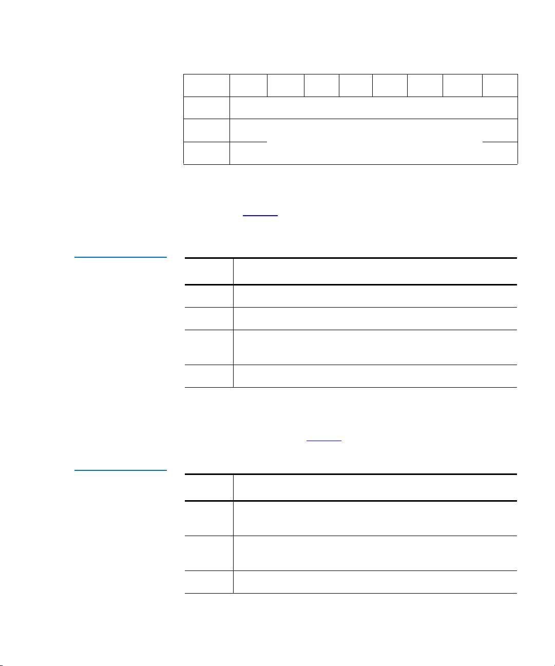
The format for this command data block is shown in table 3.
Table 7 Initialize
Element Status
Command
Bit/Byte 7 6 5 4 3 2 1 0
0
1
2
3
4
5
Logical Unit Number Reserved (00h)
NBL Reserved (00h)
Operation Code (07h)
Reserved (00h)
Reserved (00h)
Reserved (00h)
• Logical Unit Number
The Logical Unit Number must be set to 0. Field indicates the logical
unit to which the command is sent.
• NBL
•A No Bar Code Labels value of 1 specifies the inventory to not
scan the bar codes of the elements and set the corresponding
primary volume tags to empty
• A value of 0 specifies element bar code labels are to be scanned
and placed in the primary volume tags
Quantum DX-Series Software Interface Guide 13
Page 40

Chapter 2 Emulated Medium Changer SCSI Commands
Initialize Element Status with Range (E7h)
Initialize Element Status with Range (E7h) 2
The Initialize Element Status with Range command allows the host to
request an inventory of a range of elements in the DX-Series system. The
DX-Series system conducts the inventory and determines if each element
within the range contains a tape cartridge. The inventory reads each
tape’s bar code (unless commanded not to).
The DX-Series system does not accept any other commands from the host
during the inventory process.
The host can issue an Abort of the inventory for the DX-Series system. If
another Initialize Element Status command is then issued, the inventory
process is restarted from the beginning.
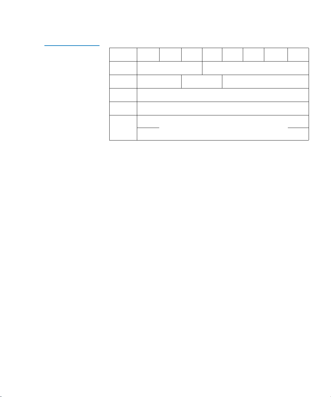
The format for this command data block is shown in table 8.
Table 8 Initialize
Element Status with
Range Command
Bit/Byte 7 6 5 4 3 2 1 0
0
1
2
3
4
5
6
7
8
9
Logical Unit Number Reserved (00h) Range
(MSB)
(MSB)
NBL Reserved (00h)
Operation Code (E7h)
Starting Element Address
Reserved (00h)
Reserved (00h)
Number of Elements
Reserved (00h)
• Logical Unit Number
The Logical Unit Number must be set to 0. Field indicates the logical
unit to which the command is sent.
(LSB)
(LSB)
14 Quantum DX-Series Software Interface Guide
Page 41

Chapter 2 Emulated Medium Changer SCSI Commands
Initialize Element Status with Range (E7h)
•Range
• Range value of 1 specifies performing the inventory over the
range specified by the Starting Element Address and Number
of Elements fields
• A value of 0 specifies performing the inventory on all elements in
the DX-Series system, ignoring the Starting Element Address
and Number of Elements fields
• Starting Element Address and Number of Elements
• These fields select the range of elements to be inventoried and are
only valid when Range value is 1
• The inventory range begins with the first element with an
address greater than or equal to the Starting Element Address,
and includes all defined elements until the indicated number of
elements have been inventoried or the last element is reached
• NBL
•A No Bar Code Labels value of 1 specifies the inventory to not
scan the bar codes of the elements and set the corresponding
primary volume tags to empty.
• A value of 0 specifies element bar code labels are to be scanned
and placed in the primary volume tags.
Quantum DX-Series Software Interface Guide 15
Page 42

Chapter 2 Emulated Medium Changer SCSI Commands
Inquiry (12h)
Inquiry (12h) 2
The host uses the Inquiry command to determine devices attached to the
SCSI bus and request a description from each device.
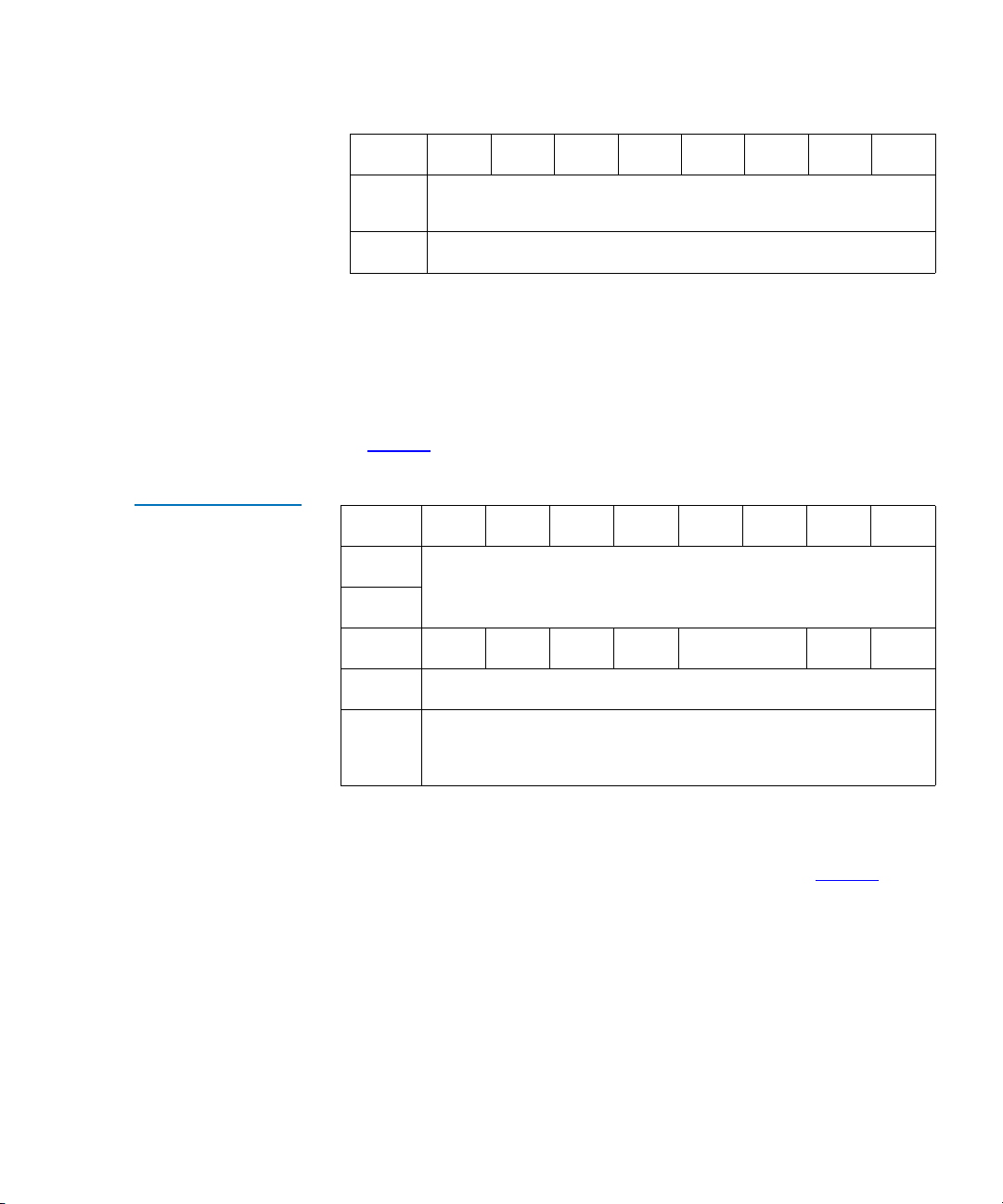
Inquiry Command Data Format
Table 9 Inquiry
Command Data
Format
The description provided by the DX-Series system identifies the device
type, manufacturer, and nature of the SCSI interface. The format for this
2
command data block is shown in
Bit/Byte 7 6 5 4 3 2 1 0
0
1
2
3
4
5
Logical Unit Number Reserved (0h) EVPD
table 9.
Operation Code (12h)
Page Code
Reserved (00h)
Allocation Length
Reserved (00h)
• Logical Unit Number
The Logical Unit Number must be set to 0. Field indicates the logical
unit to which the command is sent.
• EVPD
• When the Enable Vital Product Data (EVPD) bit is set to 0, only
Standard Inquiry Data is returned
• When the bit is set to 1, the target returns the optional vital
product data specified by Page Code field (see
• Allocation Length
Field contains the maximum data amount that the DX-Series system
may return.
16 Quantum DX-Series Software Interface Guide
table 11)
Page 43

Chapter 2 Emulated Medium Changer SCSI Commands
• Page Code
The Page Code (Byte 2 in table 9) specifies which page of vital
product data information the target shall return.
The supported Page Code is (80h) to return the Serial Number
Page (see
table 11).
Inquiry (12h)
Standard Inquiry Data Format
Table 10 Standard
Inquiry Data
The format for the Standard Inquiry Data block returned by the DX-Series
system to the initiator is shown in
2
Bit/Byte 7 6 5 4 3 2 1 0
0
1
2
3
Peripheral Qualifier (0) Peripheral Device Type (8)
RMB (1) Device-Type Modifier (00h)
ISO Version (0) ECMA Version (0)
AENC
(0)
TrmIOP
(0)
4
5
6
RelAdr
7
(MSB)
(0)
WBus32
(0)
WBus16
8 - 15
table 10.
ANSI-Approved Version
(2)
Reserved (0) Response Data Format (02h)
Additional Length (1Fh)
Reserved (0000h)
S y n c
(0)
Linked
(0)
Vendor ID
(0)
Rsvrd
(0)
CmdQue
(0)
SftRes
(0)
(LSB)
16 - 31
32 - 35
(MSB)
Product ID
(MSB)
Product Revision Level
Quantum DX-Series Software Interface Guide 17
(LSB)
(LSB)
Page 44

Chapter 2 Emulated Medium Changer SCSI Commands
Inquiry (12h)
• Peripheral Qualifier
• 0 indicates the specified DX-Series system is currently connected
• 3 indicates the specified DX-Series system cannot be supported
• Peripheral Device Type
• 08h indicates medium changer device
• 1Fh indicates unknown or no device type used in conjunction
with Peripheral Qualifier
•RMB
A Removable Medium Bit of 1 indicates medium is removable.
• Device-Type Modifier
This field is not supported and should return a value of 0.
• ISO and ECMA Version
0 code value indicates target does not claim compliance to ISO
version of SCSI (ISO IS 9316) or ECMA version of SCSI (ECMA-111).
• ANSI-Approved Version
3
2 indicates the device complies with the SCSI-2 specification.
•AENC
The asynchronous event notification capability bit of 0 indicates the
device does not support asynchronous event notification capability.
• TrmIOP
A terminate I/O process value of 0 indicates the device does not
support the TERMINATE I/O PROCESS message.
• Response Data Format
2 indicates data must be in format specified in SCSI-2 spec.
• Additional Length
The length (in bytes) of additional inquiry data available.
•RelAdr
A Relative Address of 0 indicates the device does not support
relative addressing for this DX-Series system.
•WBus32
0 bit value - DX-Series system does not support 32-bit wide transfers.
18 Quantum DX-Series Software Interface Guide
Page 45

Chapter 2 Emulated Medium Changer SCSI Commands
Inquiry (12h)
•WBus16
1 bit value indicates the DX-Series system supports 16-bit wide
transfers.
•Sync
Synchronous transfer value of 0 indicates the device does not support
synchronous data transfer.
•Linked
Linked command value of 0 indicates the device does not support
linked commands for this DX-Series system.
•CMDQue
Command queuing value of 0 indicates the device does not support
tagged command queuing for this DX-Series system.
•SftRes
• A soft reset bit of 0 indicates the device responds to the RESET
condition with a hard reset
• A soft reset bit of 1 indicates the device responds to the RESET
condition with a soft reset
• Vendor ID
The vendor ID string is selectable. The default inquiry string is P1000
and the alternate inquiry string is DX30 or DX100.
For the P1000 inquiry - this field contains the string ATLbbbbb.
For the DX30 inquiry - this field contains the string QUANTUMb
For the DX100 inquiry - this field contains the string QUANTUMb
For the DX3000 inquiry - this field contains the string QUANTUMb
For the DX5000 inquiry - this field contains the string QUANTUMb
Quantum DX-Series Software Interface Guide 19
Page 46

Chapter 2 Emulated Medium Changer SCSI Commands
Inquiry (12h)
•Product ID
The product ID is selectable. The default product ID is P1000 and the
alternate product ID are DX30 and DX100.
For the P1000 inquiry - P1000bbbb6220050
For the DX30 inquiry - DX30bbbbb6220050
For the DX100 inquiry - DX100bbbb6220050
For the DX3000 inquiry - DX3000bbb6532501
For the DX5000 inquiry - DX5000bbb6532502
Note: In the ASCII strings above, each b represents a space (20h)
and 6220050 represents the DX30 and DX100 system part
number. 6532501 represents the DX3000 system part
number. 6532502 represents the DX5000 system part
number.
• Product Revision Level
Both the P1000, DX30, DX100, DX3000, and DX5000 firmware
revision level are in the format xxxx.
Supported Vital Product Data Page
The supported vital product data pages page provides a directory of the
vital product data pages that are supported. The pages that are supported
2
are:
• Unit Serial Number Page (80h)
• Device Identification VPD page (Page 83h)
Table 11 Supported
Vital Product Data
Page
20 Quantum DX-Series Software Interface Guide
Bit/Byte 7 6 5 4 3 2 1 0
0
1
2
3
Peripheral Qualifier
Page Code (00h)
Reserved
Page length (3)
Peripheral device type
Page 47

Chapter 2 Emulated Medium Changer SCSI Commands
Inquiry (12h)
Bit/Byte76543210
Table 12 Unit Serial
Number Page (Page
80h)
4
5
6
83h - Device Identification Page
00h - (this page)
80h - Unit Serial Number Page
Unit Serial Number Page (80h) 2
The Unit Serial Number Page (Byte 2 in table 9) specifies which page of
vital product data information the target shall return.
The supported Page Code is (80h) to return the Serial Number Page
(see
table 12).
Bit/Byte 7 6 5 4 3 2 1 0
0
1
2
3
Peripheral Qualifier
Page Code (80h)
Reserved (00h)
Page length (n-3) (size of the product serial number)
Peripheral device type
4-n
Product serial number (up to 12 bytes)
Device Identification VPD page (Page 83h) 2
The device identification VPD page provides the means to retrieve
identification descriptors applying to the logical unit. Logical units may
have more than one identification descriptor (e.g. if several types of
associations of identifier are supported.
Device identifiers shall be assigned to the peripheral device and not to the
currently mounted media, in the case of removable media devices.
Quantum DX-Series Software Interface Guide 21
Page 48

Chapter 2 Emulated Medium Changer SCSI Commands
Inquiry (12h)
Table 13 Device
Identification VPD
Page 83h
Bit/Byte 7 6 5 4 3 2 1 0
0
1
2
3
4
Peripheral Qualifier (0) Peripheral Device Type (8)
Page Code (83h)
Reserved (00h)
Page Length (n-3)
Identification Descriptor list
Identification descriptor (first)
.
.
.
Identification descriptor (last)
n
• Identification Descriptor
Each identification descriptor (see table 14) contains information
identifying the logical unit, physical device, or access path used by
the command and returned parameter data. The association field
indicates the entity that the identification descriptor describes. If a
physical or logical device returns the identification descriptor with
the association field set to 0h, it shall return the same descriptor when
it is accessed through any other path.
Table 14 Identification
Descriptor
22 Quantum DX-Series Software Interface Guide
Bit/Byte 7 6 5 4 3 2 1 0
0
1
2
Reserved
Reserved
Association Identifier Type
Reserved
Code Set
Page 49
Chapter 2 Emulated Medium Changer SCSI Commands
Inquiry (12h)
Bit/Byte 7 6 5 4 3 2 1 0
Table 15 Code Set
3
4
n
(MSB)
Identifier length (n-3)
Identifier
(LSB)
•Code set
The code set field specifies the code set used for the identifier field, as
described in
table 15. This field is intended to be an aid to software that
displays the identifier field.
Value Description
0h Reserved
1h The identifier field shall contain binary values
2h The identifier field shall contain ASCII graphic codes (e.g.
code values 20h through 7Eh)
3h-Fh Reserved
Table 16 Association
• Association
The association field specifies the entity with which the identifier field is
associated, as described in
table 16.
Value Description
0h The identifier field is associated with the addressed
physical or logical device
1h The identifier field is associated with the port that received
the request
2h - 3h Reserved
Quantum DX-Series Software Interface Guide 23
Page 50

Chapter 2 Emulated Medium Changer SCSI Commands
Inquiry (12h)
• Identifier Type.
The identifier type is described in table 17
Table 17 Identifier
Type
Table 18 Device
Identification VPD
Logical Unit
Value Description
00h Reserved
1h Vendor ID followed by the product identification field from
the standard inquiry data and the serial number field from
the Serial Number Inquiry Page.
2h Canonical form of the IEEE Extended Unique Identifier, 64
bit (EIU-64)
3h FC-PH Name_Identifier
4h to fh Reserved
Bit/Byte 7 6 5 4 3 2 1 0
0
1
2
Protocol Identifier (0) Code Set (2)
Rsvd (0)
Association (0) Identifier Type (1)
Reserved (0)
3
4-n
24 Quantum DX-Series Software Interface Guide
MSB
Vendor and Product ID Serial Number
Identifier Length (n-3)
LSB
Page 51
Chapter 2 Emulated Medium Changer SCSI Commands
Inquiry (12h)
Table 19 Device
Identification VPD
World Wide Name
Bit/Byte 7 6 5 4 3 2 1 0
0
1
2
3
4-11
Protocol Identifier (0) Code Set (1)
Rsvd (0)
MSB
Association (0) Identifier Type (2)
Reserved (0)
Identifier Length (8)
IEEE extended Unique Identifier
LSB
Quantum DX-Series Software Interface Guide 25
Page 52

Chapter 2 Emulated Medium Changer SCSI Commands
Log Sense (4Dh)
Log Sense (4Dh) 2
The Log Sense command (see table 20) retrieves statistical information
maintained by the logical unit. Data is returned from the logical unit in
the Medium Changer Statistics Page (see
table 22).
Table 20 Log Sense
Command
Bit/Byte 7 6 5 4 3 2 1 0
0
1
2
3
4
5
6
7
8
9
Logical Unit Number Reserved (0) PPC(0) SP(0)
PC (1) Page Code
(MSB)
(MSB)
Operation Code (4Dh)
Reserved (0000h)
Parameter Pointer
(LSB)
Allocation Length
(LSB)
Reserved (00h)
26 Quantum DX-Series Software Interface Guide
Page 53

Chapter 2 Emulated Medium Changer SCSI Commands
Log Sense (4Dh)
• Logical Unit Number
Logical Unit Number must be set to 0. Field indicates the logical unit
to which the command is sent.
• PPC
Parameter Pointer Control field is not supported and must be set to
0.
•SP
Save Parameters field is not supported and must be set to 0.
•PC
Page Control field defines type of parameter values to be selected.
Only cumulative values are supported, therefore this field must be
set to 1.
• Page Codes
Currently, there are 3 supported page codes:
• 00h — Supported Log Page (see table 21).
• 30h — Medium Changer Statistic Page (see table 22).
• 3Fh — Return all supported pages. This is a composite of all
pages, returned sequentially. Order is Supported Log Page
followed by Medium Changer Statistic Page.
• Parameter Pointer
Field allows host to request parameter data beginning from a specific
parameter code to the maximum allocation length or the maximum
parameter code supported by the target, whichever is less. For
parameter codes, see
table 24.
• Allocation Length
Field specifies how much memory host has set aside to store log
sense information returned by the DX-Series system.
• Supported Log Page
Page returns the list of log pages supported (see table 21).
Quantum DX-Series Software Interface Guide 27
Page 54

Chapter 2 Emulated Medium Changer SCSI Commands
Log Sense (4Dh)
Table 21 Supported
Log Page
Bit/Byte 7 6 5 4 3 2 1 0
0
1
2
3
4
5
Reserved (0) Page Code (00h)
Reserved (00h)
(MSB)
Page Length (0002h)
SUPPORTED PAGE LIST
(00h)
(30h)
• Page Length
Field specifies length in bytes of the supported page list.
• Supported Page List
List of all log page codes supported. Currently, there are 2 pages
supported:
• Supported Log Page (00h)
• Medium Changer Statistics Page (30h)
(LSB)
• Medium Changer Statistics Page
Page returns medium changer statistical data (see table 22).
Table 22 Medium
Changer Statistics
Page
28 Quantum DX-Series Software Interface Guide
Bit/Byte 7 6 5 4 3 2 1 0
0
1
2
3
4 - 11
Reserved (0) Page Code (30h)
Reserved (00h)
(MSB)
Page Length
LOG PARAMETER LIST
Log Parameter (First)
(LSB)
Page 55
Chapter 2 Emulated Medium Changer SCSI Commands
Log Sense (4Dh)
Bit/Byte76543210
.
.
Table 23 Log
Parameter
x-7 - x
Log Parameter (Last)
• Page Length
Field specifies length in bytes of the log parameter list.
• Log Parameter
Each log parameter begins with a 4-byte parameter header followed
by 4 bytes of parameter value data. For the log parameter format, see
table 23.
Bit/Byte 7 6 5 4 3 2 1 0
0
(MSB)
Parameter Code
1
2
DU(0) DS(0) TSD(0) ETC(0) TMC(0) Rsv(0) LP(0)
3
(MSB)
4 - 7
Parameter Length (04h)
Parameter Value
(LSB)
(LSB)
• Parameter Code
Parameter Code field identifies which log parameter is being
transferred for that log page. For parameter codes, see
table 24.
•DU
Disable Update. Not supported, always 0.
•DS
Disable Save. Not supported, always 0.
•TSD
Target Save Disable. Not supported, always 0.
Quantum DX-Series Software Interface Guide 29
Page 56

Chapter 2 Emulated Medium Changer SCSI Commands
Log Sense (4Dh)
•ETC
Enable Threshold Comparison. Not supported, always 0.
•TMC
Threshold Met Criteria. Not supported, always 0.
•LP
List Parameter. Not supported, always 0.
• Parameter Length
All log parameter values supported in the Medium Changer
Statistics page have a length of 4 bytes.
• Parameter Value
The cumulative count of parameter as described in table 24.
Table 24 Supported
Log Parameter Codes
for 30h Page
Parameter
Code Description
8000 Number of seconds system has been
powered on
8001 Reserved 4
8010 Number of attempted moves from a bin 4
8011 Number of attempted moves to a bin 4
8012 Number of attempted moves from a drive 4
8013 Number of attempted moves to a drive 4
8014 Number of attempted moves from load port 4
8015 Number of attempted moves to load port 4
8020 Reserved 4
8021 Reserved 4
8022 Reserved 4
Size
(bytes)
4
30 Quantum DX-Series Software Interface Guide
Page 57

Chapter 2 Emulated Medium Changer SCSI Commands
Log Sense (4Dh)
Parameter
Code Description
8023 Reserved 4
8024 Reserved 4
8025 Reserved 4
8026 Reserved 4
8030 Reserved 4
8031 Reserved 4
8032 Reserved 4
8033 Reserved 4
8035 Reserved 4
8036 Reserved 4
8040 Reserved 4
8041 Reserved 4
Size
(bytes)
8042 Reserved 4
8043 Reserved 4
8044 Reserved 4
8045 Reserved 4
8050 Reserved 4
8051 Reserved 4
8052 Reserved 4
Quantum DX-Series Software Interface Guide 31
Page 58

Chapter 2 Emulated Medium Changer SCSI Commands
Mode Select (15h)
Mode Select (15h) 2
The Mode Select command provides a means for the host to specify
parameters to the DX-Series system. The DX-Series system supports:
• Element Address Assignment Page 1Dh
• Vendor Unique Page 20h
• Vendor Unique Page 00h
Table 25 Mode
Select Command
Bit/Byte 7 6 5 4 3 2 1 0
0
1
2
3
4
5
Logical Unit Number PF (1) Reserved (0)
Operation Code (15h)
Reserved (0000h)
Parameter List Length
Reserved (00h)
• Logical Unit Number
The Logical Unit Number field must be set to 0. This field indicates
the logical unit to which the command is sent.
• SP - Save Page
• When set to 0, the Save Page field performs mode select without
saving
• When set to 1, Save Page performs Mode Select and saves it in
nonvolatile memory
SP
•PF
When set to 1, the Page Format field indicates the Mode Select
Parameters are formatted as specified in the SCSI-2 specification.
• Parameter List Length
32 Quantum DX-Series Software Interface Guide
Page 59

Chapter 2 Emulated Medium Changer SCSI Commands
Mode Select (15h)
The PLL field indicates the length of the parameter list. The list
length should reflect the combined length of all data pages being sent
with the Mode Select command. Mode Select Data pages are
shown in
table 26, table 27, and table 28.
The format for Mode Select Vendor Unique Page 20h is shown in
table 26.
Table 26 Mode
Select Data - Vendor
Unique Page 20h
Bit/Byte 7 6 5 4 3 2 1 0
0
1
2
3
PS (0) Rsvd (0) Page Code (20h)
Page Length (02h)
Reserved (00h)
Reserved (00h) ADU EXB(0)
SER(1)
AC DLR
• PS - Parameters Savable
This bit is only used with the Mode Sense command. This bit is
reserved for Mode Select command and should be set to 0.
• DLR-Drive Load Retry
This bit is ignored. It can be set to 1 or 0 for compatibility with hosts.
• SER
This bit enables Drive Serialization, which enables the reporting of
drive serial numbers in the Alternative Volume Tag (AVoltag) field
of the drive Read Element Status. The default setting is Enabled
Note: This must always be set to 1. Any attempt to disable this
bit will result in a check condition (05 26 00).
.
• AC-Auto Clean
When this bit is set to 1, automatic drive cleaning feature is enabled
When set to 0, automatic drive cleaning is disabled. This bit is
ignored. It can be set to 0 or 1 for compatibility with hosts
Note: The normal state of automatic drive cleaning is
“disabled.”
Quantum DX-Series Software Interface Guide 33
Page 60

Chapter 2 Emulated Medium Changer SCSI Commands
Mode Select (15h)
• ADU-Auto Drive Unload
• When this bit is set to 1, the DX-Series system unloads a tape
drive as part of the Move Medium command (default condition)
• When set to 0, the auto drive unload feature is disabled
• EXB-Exabyte Emulation
• When this bit is set to 1, the DX-Series system emulates an
Exabyte EXB-120 - this setting changes the SCSI command set’s
behavior
• When set to 0, the DX-Series system SCSI interface operates in the
default manner as described in this document
The format for Mode Select Vendor Unique Page 00h is shown in
table 27.
Table 27 Mode
Select Data - Vendor
Unique Page 00h
Bit/Byte 7 6 5 4 3 2 1 0
0
1
2
3
4 - 63
PS
(0)
AInit UInit (0) Parity (0) NBL Rsrvd (0)
Rsrvd
(0)
Page Code (00h)
Page Length (3Eh)
NRDC
(0)
Maximum Parity Retries (00h)
Display Messages (00h)
• PS - Parameters Savable
This bit is only used with the Mode Sense command (see table 32).
This bit is reserved for Mode Select command and should be set to 0.
•AInit
• When set to 1 the DX-Series system ensures that all elements
have been inventoried before entering the On-line state
• If set to 0, the DX-Series system only inventories itself when
commanded to by the Init Element Status or Init Element
Status with Range command
MDC
(0)
34 Quantum DX-Series Software Interface Guide
Page 61

Chapter 2 Emulated Medium Changer SCSI Commands
Mode Select (15h)
•UInit
Not supported.
•Parity
Not supported.
• NBL - No bar code Labels
• Valid only if the AInit field value is 1 - when DX-Series system
performs an inventory due to going on-line, and the NBL field
value is 1, bar codes are not scanned and primary volume tags
are set to empty
•If NBL field is set to 0, when the DX-Series system performs an
inventory due to going on-line bar codes are scanned and their
value placed in the corresponding primary volume tag
• NRDC - Not Ready Display Control
Not supported.
• MDC - Message Display Control
Not supported.
Table 28 Mode
Select Data - Element
Address Assign. Page
• Maximum Parity Retries
Not supported.
• Display Message
Not supported.
The format for the Element Address Assignment Page is shown in
table 28.
Bit/Byte 7 6 5 4 3 2 1 0
0
1
2
3
Quantum DX-Series Software Interface Guide 35
PS (0)
(MSB)
Rsrvd
(0)
Parameter Length (12h)
First Medium Transport Element Address
Page Code (1Dh)
(LSB)
Page 62

Chapter 2 Emulated Medium Changer SCSI Commands
Mode Select (15h)
Bit/Byte76543210
4
5
6
7
8
9
10
11
12
13
14
15
16
17
(MSB)
Number of Medium Transport Elements (0001h)
(LSB)
(MSB)
First Storage Element Address
(LSB)
(MSB)
Number of Storage Elements
(LSB)
(MSB)
First Import Export Element Address
(LSB)
(MSB)
Number of Import Export Elements
(LSB)
(MSB)
First Data Transport Element Address
(LSB)
(MSB)
Number of Data Transport Elements
(LSB)
18
Reserved (0000h)
19
• PS - Parameters Savable
This bit is only used with the Mode Sense command (see table 32).
Reserved for Mode Select command and should be set to 0.
• First Medium Transport Element Address
Field specifies the first medium transport element contained in the
medium changer (other than default medium transport address of 0).
• Number of Medium Transport Elements
Field defines total number of medium transport elements contained
in the medium changer.
36 Quantum DX-Series Software Interface Guide
Page 63

Chapter 2 Emulated Medium Changer SCSI Commands
Mode Select (15h)
• First Storage Element Address
Field specifies the first storage element contained in the medium
changer.
• Number of Storage Elements
Field defines total number of storage elements contained in the
medium changer.
• First Import/Export Element Address
Field specifies the first import/export element contained in the
medium changer.
Tech Tip: The DX-Series system does not support First Import/
Export Element Address.
• Number of Import/Export Elements
Field defines the total number of import/export elements contained
in the medium changer.
Table 29 Changeable
Parameters within
MODE SELECT
Tech Tip: The DX-Series does not support Number of Import/
Export Elements.
• First Data Transport Element Address
The First Data Transfer Element Address field specifies the first
data transfer element contained in the medium changer.
• Number of Data Transport Elements
Field defines the total number of data transfer elements contained
within the medium changer and accessible to the medium transport
elements.
Parameter Default Minimum Maximum
AInit(00h)
10 1
NBL(00h) 0 0 1
AC(20h)
00 1
Quantum DX-Series Software Interface Guide 37
Page 64

Chapter 2 Emulated Medium Changer SCSI Commands
Mode Select (15h)
Parameter Default Minimum Maximum
DLR(20h) 0 0 1
ADU(20h) 1 0 1
38 Quantum DX-Series Software Interface Guide
Page 65

Chapter 2 Emulated Medium Changer SCSI Commands
Mode Sense (1Ah)
Mode Sense (1Ah) 2
The SCSI Mode Sense command provides a general method for a host to
obtain current parameter settings of a target device. The host selects the
set parameters to be returned by setting the Page Code field in the
command block. This code selects the page of parameter information to
be returned by the target.
The DX-Series system supports the three medium changer device
parameter pages defined in the SCSI-2 specification and two vendor
unique pages:
• Element Address Assignment Page
• Transport Geometry Parameters Page
• Device Capabilities Pag e
• Vendor Unique Page 20h
• Vendor Unique Page 00h
The host can request all pages with a single command using the Return
All Pages page code as described in the SCSI-2 specification.
The format for the Mode Sense command block is shown in table 30.
Quantum DX-Series Software Interface Guide 39
Page 66

Chapter 2 Emulated Medium Changer SCSI Commands
Mode Sense (1Ah)
Table 30 Mode
Sense Command
Bit/Byte 7 6 5 4 3 2 1 0
0
1
2
3
4
5
Logical Unit Number
PC Page Code
Operation Code (1Ah)
Rsrvd
(0)
Reserved (00h)
Allocation Length
Reserved (00h)
DBD Reserved (00)
• Logical Unit Number
The Logical Unit Number field must be set to 0. This field indicates
the logical unit to which the command is sent.
• DBD
• When the Disable Block Descriptors field is set to 0, the target
may return 0 or more block descriptors in the returned Mode
Sense data at the target’s discretion
•A DBD bit of 1 specifies the target does not return any block
descriptors in the returned Mode Sense data
•PC
The Page Control field defines parameter type values to return:
• 0 — requests current parameter values for the specified page
code for the DX-Series system - current values returned are the
default values
• 1 — requests the target to return the changeable parameter mask
for the page code specified - the page indicates which parameters
are changeable
• 2 — requests the target return the default values for the page
code specified
• 3 — requests the target return saved values for the page code
specified - only the Vendor Unique Page has changeable/
savable parameters
40 Quantum DX-Series Software Interface Guide
Page 67

Chapter 2 Emulated Medium Changer SCSI Commands
Mode Sense (1Ah)
• Otherwise, the current setting for each parameter is always the
same as the setting that parameter had when the DX-Series
system was turned on
• Page Codes
The valid page codes are:
• 00h — Vendor Unique Page, length 44h
• 1Dh — Element Address Assignment Page, length 18h
• 1Eh — Transport Geometry Parameters Page, length 08h
• 1Fh — Device Capabilities Page, length 18h
• 20h — Vendor Unique Page, length 08h
• 3Fh — Return All Pages, length 74h
The parameter data returned for each Mode Sense command is preceded
by a Mode Parameter header block. The header block is then followed by
either the requested parameter page or all pages if the Return All Pages
page code was used.
The format for the Mode Sense header block is shown in table 31.
Table 31 Mode
Sense Data Header
Bit/Byte 7 6 5 4 3 2 1 0
0
1
2
3
Mode Sense Data Length
Medium Type (00h)
Device-Specific Parameter (00h)
Block Descriptor Length (00h)
• Mode Data Length
Field is set to the data amount following the Data Length field in
bytes. This includes the last 3 bytes in the header block as well as all
bytes in the parameter page or pages.
• Medium Type Code
Field is reserved for medium changer devices.
Quantum DX-Series Software Interface Guide 41
Page 68

Chapter 2 Emulated Medium Changer SCSI Commands
Mode Sense (1Ah)
• Device-Specific Parameter
Field is reserved for medium changer devices.
• Block Descriptor Length
Field is reserved for medium changer devices.
The format for Mode Sense Vendor Unique Page 00h is shown in
table 32.
Table 32 Mode
Sense Data - Vendor
Unique Page 00h
Bit/Byte 7 6 5 4 3 2 1 0
0
1
2
3
4 - 63
PS (1)
AInit
Rsrvd
(0)
UInit
(0)
Page Code (00h)
Page Length (3Eh)
Parity
Maximum Parity Retries (00h)
NBL
(0)
Display Messages (00h)
Rsrvd
(0)
NRDC
(0)
MDC (0)
• PS-Parameters Savable
This bit is always set to 1 indicating this page can be saved to
nonvolatile memory.
•AInit
• When this value is set to 1, the DX-Series system insures all
elements have been inventoried before entering the on-line state
• If set to 0, the DX-Series system only inventories itself when
commanded by a Init Element Status or Init Element Status
with Range command
•UInit
Not supported.
•Parity
Not supported.
42 Quantum DX-Series Software Interface Guide
Page 69

Chapter 2 Emulated Medium Changer SCSI Commands
Mode Sense (1Ah)
• NBL - No Bar Code Labels
• Field is valid only if the AInit field value is 1-when the DX-Series
system performs an inventory due to going on-line, and NBL
field is 1, bar codes are not scanned and primary volume tags are
set to empty
• If this field is set to 0, when the DX-Series system performs an
inventory due to going on-line, bar codes are scanned and their
value placed in the corresponding primary volume tag
• NRDC - Not Ready Display Control
Not supported.
• MDC - Message Display Control
Not supported.
• Maximum Parity Retries
Not supported.
• Display Message
Not supported.
Table 33 Mode
Sense Data - Element
Address Assign. Page
The format for the Element Address Assignment Page is shown in
table 33.
Bit/Byte 7 6 5 4 3 2 1 0
0
1
2
3
4
5
6
7
Quantum DX-Series Software Interface Guide 43
PS (1)
(MSB)
(MSB)
(MSB)
Rsrvd
(0)
Parameter Length (12h)
First Medium Transport Element Address
Number of Medium Transport Elements (0001h)
First Storage Element Address
Page Code (1Dh)
(LSB)
(LSB)
(LSB)
Page 70

Chapter 2 Emulated Medium Changer SCSI Commands
Mode Sense (1Ah)
Bit/Byte76543210
8
(MSB)
9
Number of Storage Elements
(LSB)
10
11
12
13
14
15
16
17
18
19
(MSB)
First Import Export Element Address
(MSB)
Number of Import Export Elements
(MSB)
First Data Transport Element Address
(MSB)
Number of Data Transport Elements
Reserved (0000h)
• PS-Parameters Savable
This bit is always set to 1 indicating this page can be saved to
nonvolatile memory.
• First Medium Transport Element Address
(LSB)
(LSB)
(LSB)
(LSB)
Field identifies the first medium transport element contained in the
medium changer (other than the default medium transport address
of 0).
• Number of Medium Transport Elements
Field defines total number of medium transport elements contained
in the medium changer.
44 Quantum DX-Series Software Interface Guide
Page 71

Chapter 2 Emulated Medium Changer SCSI Commands
Mode Sense (1Ah)
• First Storage Element Address
Field identifies the first storage element contained in the medium
changer.
• Number of Storage Elements
Field defines total number of storage elements contained in the
medium changer.
• First Import/Export Element Address
Field identifies the first import/export element contained in the
medium changer.
Tech Tip: The DX-Series system does not support First Import/
Export Element Address.
• Number of Import/Export Elements
Field defines total number of import/export elements in the medium
changer.
Tech Tip: The DX-Series system does not support Number of
Import/Export Elements.
• First Data Transport Element Address
The First Data Transfer Element Address field identifies the first
data transfer element contained in the medium changer.
• Number of Data Transport Elements
Field defines total number of data transfer elements contained within
the medium changer and accessible to medium transport elements.
The format for the Trans port Geomet ry Parameters Page is shown
in
table 34.
Quantum DX-Series Software Interface Guide 45
Page 72

Chapter 2 Emulated Medium Changer SCSI Commands
Mode Sense (1Ah)
Table 34 Mode
Sense Data - Trans.
Geometry Para. Page
Bit/Byte 7 6 5 4 3 2 1 0
0
PS (0)
1
2
3
Rsrvd
(0)
Parameter Length (02h)
TRANSPORT GEOMETRY DESCRIPTOR
Reserved (00h)
Member Number In Transport Element Set (00h)
Page Code (1Eh)
• PS- Parameters Savable
This bit of 0 indicates the target is not capable of saving the page in a
nonvolatile vendor-specific location.
• Parameter Length
There are 2 bytes of parameter information.
• Transport Geometry Descriptor
The geometry of each medium transport element is defined using a
two-byte field.
Rotate
(0)
•Rotate
A rotate bit of 0 indicates the medium transport element does not
support media rotation.
• Member Number In Transport Element Set
The first element in a set has a member number of 0.
The format for the Device Capabilities Page is shown in table 35.
46 Quantum DX-Series Software Interface Guide
Page 73

Chapter 2 Emulated Medium Changer SCSI Commands
Mode Sense (1Ah)
Table 35 Mode
Sense Data - Device
Capabilities Data
Bit/Byte 7 6 5 4 3 2 1 0
0
1
2
3
4
5
6
7
8 - 11
12
13
PS (0)
Rsrvd
(0)
Reserved (0h)
Reserved (0h)
Reserved (0h)
Reserved (0h)
Reserved (0h)
Reserved (0h)
Reserved (0h)
Page Code (1Fh)
Parameter Length (12h)
a
StorDT
StorIEb
(1)
Reserved (0h)
MT→DT
(1)
ST→DT
IE→DT (0) IE→IE (0) IE→ST (0)
DT→DT
ST→IE (0) ST→ST (1)
(1)
DT→IE (0)
(1)
Reserved (00000000h)
MT↔DT
(0)
ST↔DT
ST↔IE (0) ST↔ST (0)
(0)
(0)
MT→IE
(0)
MT↔IE
(0)
StorSTc
(1)
MT→ST
(1)
DT→ST
(1)
MT↔ST
(0)
StorMTd
MT→MT
ST→MT
IE→MT
DT→MT
MT↔MT
ST↔MT
(1)
(0)
(1)
(0)
(1)
(0)
(0)
(0)
IE↔MT
(0)
DT↔MT
(0)
14
15
16 - 19
Reserved (0h)
Reserved (0h)
IE↔DT
(0)
DT↔DT
(0)
Reserved (00000000h)
IE↔IE (0) IE↔ST (0)
DT↔IE
(0)
DT↔ST
a.DT = Data Transfer Element (Tape Drive)
b.IE = Import/Export Element (load port)
c.ST = Storage Element (Bin)
d.MT = Medium Transport Element (Gripper Mechanism)
The StorDT, StorIE, StorST, and StorMT fields indicate if an element of
the indicated type (DT, IE, ST, or MT) is capable of storing a tape
cartridge.
Quantum DX-Series Software Interface Guide 47
Page 74

Chapter 2 Emulated Medium Changer SCSI Commands
Mode Sense (1Ah)
The XX→YY fields indicate if a transfer from an element of type XX is
possible to an element of type YY. A 1 in any of these fields indicates that
all Move Medium commands where the source element is type XX and
destination element is type YY are supported. A 0 in these fields indicates
the move may or may not be valid depending on the particular element
requested.
The DX-Series system does not support the Exchange Medium
command. Bytes 12 through 15 in this parameter page contain the
individual fields specifying the DX-Series system exchange capabilities.
Since the DX-Series system has no exchange capability, all of these fields
are 0.
The format for Mode Sense Vendor Unique Page 20h is shown in
table 36.
Table 36 Mode
Sense Data - Vendor
Unique Page 20h
Bit/Byte 7 6 5 4 3 2 1 0
0
1
2
3
PS (1) Rsvd (0) Page Code (20h)
Page Length (02h)
Reserved (00h)
Reserved (00h) ADU EXB
SER
AC DLR
• PS-Parameters Savable
This bit is always set to 1 indicating that this page can be saved to
nonvolatile memory.
• Page Code
The page code value of 20h is used to indicate a vendor unique page,
in page format.
• Page Length
The page length is fixed at a value of 2 bytes.
• SER
This bit enables Drive Serialization, which enables reporting the
drive serial numbers in the Alternative Volume Tag (AVoltag) field
of the drive Read Element Status. The default setting is Enabled.
48 Quantum DX-Series Software Interface Guide
Page 75

Chapter 2 Emulated Medium Changer SCSI Commands
Mode Sense (1Ah)
• AC-Auto Clean
• If this bit is set to 1 the current state of automatic drive cleaning is
“enabled”
• When it is set to 0, the feature is “disabled”
• DLR-Drive Load Retry
This bit is ignored. Can be set to 1 or 0 for compatibility.
• ADU-Auto Drive Unload
• When bit is set to 1, the DX-Series system unloads a tape drive as
part of the Move Medium command (default condition)
• When set to 0, the auto drive unload feature is disabled
Quantum DX-Series Software Interface Guide 49
Page 76

Chapter 2 Emulated Medium Changer SCSI Commands
Move Medium (A5h)
Move Medium (A5h) 2
The host uses the Move Medium command to move a tape cartridge from
one element to another within a DX-Series system. The host specifies the
source element and the destination element in the command block. The
DX-Series system then moves the tape cartridge contained in the source
element to the empty destination element.
If the Mode Select Data ADU (auto drive unload) bit is set to 1, and the
source element is a tape drive, the DX-Series system unloads the tape
drive as part of the Move Medium command.
The source and destination elements can be of any type: storage, medium
transport, import/export, or data transport element. The valid
combinations of source element type and destination element type are
summarized in the Mode Sense Device Capabilities Parameter Page
(see
table 35).
If a valid source element type and destination element type are specified,
the command is valid but the operation may still not be possible. In this
case the DX-Series system returns check condition status and sets the
sense key to Illegal Request.
The Additional Sense Code and Additional Sense Code Qualifier
indicate why an operation cannot be carried out. For example, this might
occur if the specified source element or destination element does not
contain a tape cartridge. For a summary of the conditions, sense key, and
additional sense encoding, see
table 226 on page 279.
The format for the Move Medium command block is shown in table 37.
Table 37 Move
Medium Command
50 Quantum DX-Series Software Interface Guide
Bit/Byte 7 6 5 4 3 2 1 0
0
1
2
3
Logical Unit Number Reserved (00h)
(MSB)
Operation Code (A5h)
Transport Element Address (0000h)
(LSB)
Page 77

Chapter 2 Emulated Medium Changer SCSI Commands
Move Medium (A5h)
Bit/Byte76543210
4
5
6
7
8
9
10
11
(MSB)
Source Element Address
(MSB)
Destination Element Address
Reserved (0000h)
Reserved (00h)
Reserved (00h)
• Logical Unit Number
The Logical Unit Number must be set to 0. This field indicates the
logical unit to which the command is sent.
• Transport Element Address
The default medium transport element address of 0 or the medium
transport element address specified by the Mode Sense Data can be
used.
(LSB)
(LSB)
Invert
(0)
• Source Element Address
The source element address specifies the location from which the
medium is taken.
• Destination Element Address
The destination address specifies the location to which the medium is
moved.
•Invert
The medium changer does not support medium rotation for handling
double-sided media. The Invert bit must be set to 0.
Quantum DX-Series Software Interface Guide 51
Page 78

Chapter 2 Emulated Medium Changer SCSI Commands
Position To Element (2Bh)
Position To Element (2Bh) 2
The Position To Element command is used by the host to position the
medium transport element in front of another element within a DX-Series
system. The host specifies the destination element in the command block.
The DX-Series system then moves the transport element in front of the
destination element.
The destination element can be one of these types:
•Storage
• Import/Export
Tech Tip: The DX-Series system does not support import/
export.
• Data Transfer
If the address is in error, the DX-Series system returns check condition
status and sets the sense key to Illegal Request.
The format of the Position To Element command block is shown
table 38.
Table 38 Position To
Element Command
52 Quantum DX-Series Software Interface Guide
Bit/Byte 7 6 5 4 3 2 1 0
0
1
2
3
4
5
Logical Unit Number Reserved (00h)
(MSB)
(MSB)
Operation Code (2Bh)
Transport Element Address (0000h)
Destination Element Address
(LSB)
(LSB)
Page 79

Chapter 2 Emulated Medium Changer SCSI Commands
Position To Element (2Bh)
Bit/Byte76543210
6
Reserved (00h)
7
8
9
Reserved (00h)
Reserved (00h)
• Logical Unit Number
The Logical Unit Number must be set to 0. This field indicates the
logical unit to which the command is sent.
• Transport Element Address
The default medium transport element address of 0 or the medium
transport element address specified by the mode sense data can be
used.
• Destination Element Address
The destination address specifies the location to which the medium
transport element is moved.
•Invert
The medium changer does not support medium rotation for handling
double-sided media. The invert bit must be set to 0.
Invert
(0)
Quantum DX-Series Software Interface Guide 53
Page 80

Chapter 2 Emulated Medium Changer SCSI Commands
Read Element Status (B8h)
Read Element Status (B8h) 2
The host can determine the status of any DX-Series system element by
issuing a Read Element St atus command. The command can specify the
element type:
• Medium Transfer
•Storage
• Import/Export
Tech Tip: The DX-Series system does not support import/
export.
• Data Transfer
• Starting Address
• Number of elements for which status information is to be returned
The DX-Series system automatically updates its internal element status
every time the status changes. The DX-Series system inventory initializes
the information and it is updated with each move. Because the
information is updated with each move, no action is required by the DXSeries system other than returning the information it has stored.
The format for the Read Element Status command block is shown in
table 39.
Table 39 Read
Element Status
Command
54 Quantum DX-Series Software Interface Guide
Bit/Byte 7 6 5 4 3 2 1 0
0
1
2
3
4
5
Logical Unit Number VolTag Element Type Code
(MSB)
(MSB)
Operation Code (B8h)
Starting Element Address
Number of Elements
(LSB)
(LSB)
Page 81
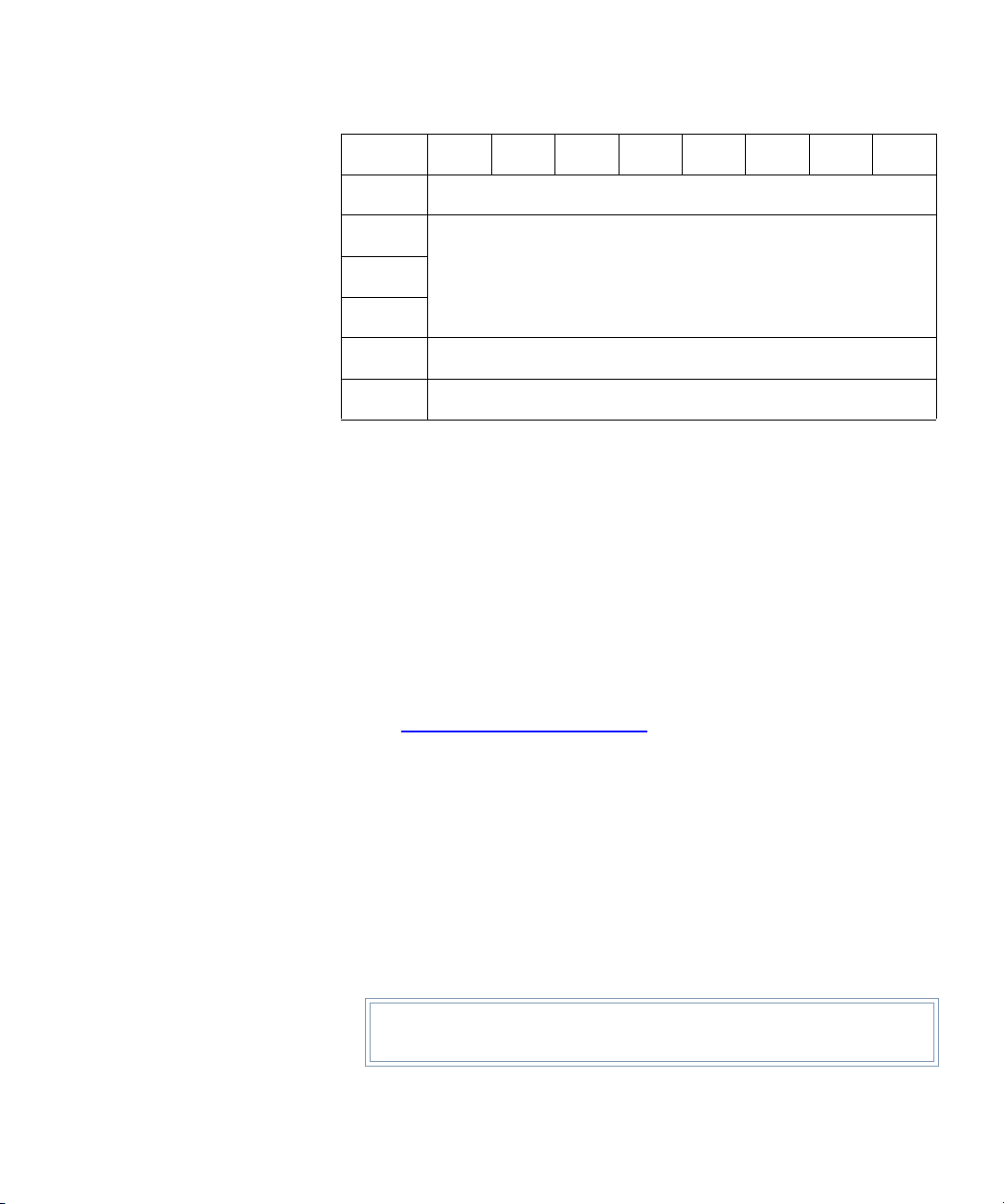
Chapter 2 Emulated Medium Changer SCSI Commands
Read Element Status (B8h)
Bit/Byte76543210
10
11
6
7
8
9
(MSB)
Reserved (00h)
Allocation Length
Reserved (00h)
Reserved (00h)
• Logical Unit Number
The Logical Unit Number is 0.
•VolTag
•The Volume Tag field (VolTa g) indicates whether the volume tag
information associated with each tape cartridge should be
returned as part of the status information.
• The volume tag (or bar code) is updated for each tape cartridge
whenever it is moved with a Move Medium command.
• The volume tag information for all tape cartridges can also be
updated using the Initialize Element Status command (see
Initialize Element Status (07h) on page 13). Since tape cartridges
are a single-sided media, only a single volume tag is supported
per tape cartridge.
(LSB)
• Element Type Code
This field indicates which element type is reported:
• 0 indicates all element types reported
• 1 indicates medium transport element
• 2 indicates storage element
• 3 indicates import/export element
Tech Tip: The DX-Series system does not support import export
elements.
Quantum DX-Series Software Interface Guide 55
Page 82

Chapter 2 Emulated Medium Changer SCSI Commands
Read Element Status (B8h)
• 4 indicates data transfer elements
• Starting Element Address and Number of Elements
These fields are used to select the range of elements to report. Within
this range, no status information is reported for an undefined
element address.
• Only elements matching the indicated type are returned
• No elements with an address smaller than the Starting Element
Address are reported
• Beginning with the first defined element with an address greater
than or equal to the Starting Element Address, all defined, type
matching elements are reported until reports for the indicated
number of elements have been returned
• Allocation Length
This field specifies how much memory the host has set aside to store
the status information returned by the DX-Series system.
• This field should be set to a number that is large enough to store
the status information for the requested number of elements
• If the field is not large enough, the DX-Series system only reports
the status information for the number of elements whose status
information fits within the allocated space
The returned Read Element Status Data has the general structure as
depicted in
56 Quantum DX-Series Software Interface Guide
figure 1.
Page 83

Chapter 2 Emulated Medium Changer SCSI Commands
Read Element Status (B8h)
Figure 1 Read
Element Status Data
General Structure
Read Element Status Data
Read Element Status Data Header
Element Status Data Page (first or only)
Element Status Data Page Header
Element Descriptor (first or only)
.
.
.
Other Element Descriptors (if any)
.
.
.
Other Status Data Pages (if any)
A single Read Element Status Data Header is returned along with one
or more element status pages. The Read Element Status Data Header
indicates the address of the first element reported, number of elements
reported, and the report size for all requested data.
The report size is given in bytes.
• The size is the total number of bytes that would be contained in the
report for all requested data minus 7
The Read Element Status command can be given with an Allocation
Length of 8 to determine how much space must be allocated to transfer
all status data requested by the command.
The format for the Read Element St atus Data is shown in table 40.
Quantum DX-Series Software Interface Guide 57
Page 84

Chapter 2 Emulated Medium Changer SCSI Commands
Read Element Status (B8h)
Table 40 Read
Element Status Data
Bit/Byte 7 6 5 4 3 2 1 0
0
1
2
3
4
5
6
7
8 - X
(MSB)
First Element Address Reported
(MSB)
Number of Elements Reported
Reserved (00h)
(MSB)
Byte Count of Report Available
One or More Element Status Page(s)
• First Element Address Reported
Indicates element address of element with smallest element address
found to meet the command description block request.
• Number of Elements Reported
• Indicates number of elements meeting the request in the
command descriptor block
(LSB)
(LSB)
(LSB)
• Element status is returned if sufficient allocation length was
specified
• Byte Count of Report Available
Indicates number of bytes of element status page data available for all
elements meeting the request in the command descriptor block.
From 1 to 4 Element Status Pages can be returned.
• One page is returned for each element type with status information
• Each page contains a header and 1 or more element descriptors
• Each element descriptor reports the status for a single DX-Series
system element
58 Quantum DX-Series Software Interface Guide
Page 85

Chapter 2 Emulated Medium Changer SCSI Commands
Read Element Status (B8h)
The page header (bytes 0-7) defines the contents of the element
descriptors for the elements of that type. The format of a status page is
shown in
table 41.
Table 41 Element
Status Page
Bit/Byte 7 6 5 4 3 2 1 0
0
1
2
3
4
5
6
7
8 - X
PVol
Tag
(MSB)
(MSB)
AVol
Tag
Byte Count of Descriptor Data Available
Element Type Code
Reserved (00h)
Element Descriptor Length
Reserved (00h)
One or More Element Descriptors
•PVolTag
•A Primary Volume Tag field value of 1 indicates the primary
volume tag information field is present in each of these element
descriptor blocks
(LSB)
(LSB)
• A value of 0 indicates these bytes are omitted from the element
descriptors that follow
•AVolTag
•An Alternate Volume Tag field value of 1 indicates the alternate
volume tag information field is present in each of these element
descriptor blocks
• A value of 0 indicates these bytes are omitted from the element
descriptors that follow
• Element Descriptor Length
Field indicates the number of bytes in each element descriptor.
Quantum DX-Series Software Interface Guide 59
Page 86

Chapter 2 Emulated Medium Changer SCSI Commands
Read Element Status (B8h)
• Byte Count of Descriptor Data Available
Byte Count of Descriptor Data Available indicates the number of
bytes (minus 7) of descriptor data (excluding this header) that are
returned for the descriptors of the specified type if an adequate
allocation length had been specified
There are 4 types of element descriptor blocks, 1 for each element type.
• There are several fields found in more than 1 element type descriptor,
as well as fields which are unique to an element descriptor
• Fields found in more than 1 type of element descriptor are indicated
by the same name in the following illustrations and descriptions
• The format of an descriptor for an element of the medium transport
element type is shown in
table 42.
Table 42 Medium
Transport Element
Descriptor
Bit/Byte 7 6 5 4 3 2 1 0
0
1
2
3
4
5
6
7
8
9
10
11
(MSB)
SValid
(0)
Element Address
Reserved (00h) Except
Reserved (00h)
Additional Sense Code
Additional Sense Code Qualifier
Reserved (000000h)
Invert
(0)
Source Storage Element Address (0000h)
Reserved (00h)
Rsrvd
(0)
(LSB)
Full
60 Quantum DX-Series Software Interface Guide
Page 87

Chapter 2 Emulated Medium Changer SCSI Commands
Read Element Status (B8h)
Bit/Byte76543210
12 - 47
48 - 51
52
53
Primary Volume Tag Information
(Field omitted if PVolTag = 0)
Reserved (00000000h)
Vendor Unique (0000h)
• Element Address
This field indicates the address of the element being reported by that
element descriptor.
• Except
• When the element is in a normal state, it is set to 0
• When the element is in an abnormal state, it is set to 1
• Information on the abnormal state is available in the Additional
Sense Code and Additional Sense Code Qualifier fields
•Full
•The Full field is set to 1 whenever the element contains a tape
cartridge
• It is set to 0 otherwise
• Additional Sense Code and Additional Sense Code Qualifier
These fields are only valid if the Exception field is set to one.
• SValid, Invert, and Source Storage Element Address
This field, and the invert bit information value of 0 indicates these
fields are not valid (
table 44).
• Primary Volume Tag Information
If the Volume Tag information was requested in the command block
(VolTag=1), the Primary Volume Tag Information field is included
in the element descriptor. This field contains the information read
from the tape cartridge bar code label; its format is shown in
Quantum DX-Series Software Interface Guide 61
table 43.
Page 88

Chapter 2 Emulated Medium Changer SCSI Commands
Read Element Status (B8h)
Table 43 Primary
Volume Tag
Information
Table 44 Storage
Element Descriptor
Bit/Byte 7 6 5 4 3 2 1 0
12 - 43
Volume Identification Field
44
Reserved (0000h)
45
46
Volume Sequence Number (0000h)
47
• Volume Identification Field
A left justified sequence of ASCII characters representing the bar
code scanned from the cartridge followed by blanks 20h.
• Volume Sequence Number
This field is reserved and set to 0.
Bit/Byte 7 6 5 4 3 2 1 0
0
1
(MSB)
Element Address
(LSB)
2
3
4
5
Reserved (0h) Access Except
Reserved (00h)
Additional Sense Code
Additional Sense Code Qualifier
6
7
Reserved (000000h)
8
9
SValid
Invert
(0)
62 Quantum DX-Series Software Interface Guide
Reserved (00h)
Rsrvd
(0)
Full
Page 89

Chapter 2 Emulated Medium Changer SCSI Commands
Read Element Status (B8h)
Bit/Byte76543210
10
Source Storage Element Address
11
12 - 47
48 - 51
52
53
Primary Volume Tag Information
(Field omitted if PVolTag = 0)
Reserved (00000000h)
Vendor Unique (0000h)
• Element Address
This field indicates the address of the element being reported by that
element descriptor.
• Access
• An access bit value of 1 indicates that access to the element by a
medium transport element is allowed
• The access bit may be set to 0 or 1 for the bins in the 2 removable
packs
• Access bit is always set to 1 for the other non-removable bins in
the system
• Except
• When the element is in a normal state, it is set to 0
• When the element is in an abnormal state, it is set to 1
• Information on the abnormal state is available in the Additional
Sense Code and Additional Sense Code Qualifier fields in the
element descriptor. For the meaning of the codes contained in the
two Sense Code fields, see
Request Sense (03h) on page 75.
•Full
•The Full field is set to 1 whenever the element contains a tape
cartridge
• It is set to 0 otherwise
• Additional Sense Code and Additional Sense Code Qualifier
Quantum DX-Series Software Interface Guide 63
Page 90

Chapter 2 Emulated Medium Changer SCSI Commands
Read Element Status (B8h)
These fields are only valid if the Exception field is set to 1. SValid
•The SValid bit is set to 1 if the information in the Source Storage
Element Address field is valid
• If information is unknown (due to a door open or power on
condition), the SValid bit is set to 0
•Invert
The Invert field is not supported and is set to 0.
• Source Storage Element Address
Source Storage Element Address represents the address of the last
storage element that held the cartridge. The SValid field indicates
whether this information is valid.
• Primary Volume Tag Information
If the Volume Tag information is requested in the command block
(VolTag=1), then the Primary Volume Tag Information field is
included in the element descriptor. For format, see
The layout of an element descriptor for an element of the import /export
element type is illustrated in
table 43.
table 45.
T able 45 Import/Export
Element Descriptor
64 Quantum DX-Series Software Interface Guide
Bit/Byte 7 6 5 4 3 2 1 0
0
1
2
3
4
5
6
7
8
(MSB)
Reserved (0)
Element Address
Import
Enable
Additional Sense Code Qualifier
Export
Enable
Reserved (00h)
Additional Sense Code
Reserved (000000h)
Access Except
Import
Export
(LSB)
Full
Page 91

Chapter 2 Emulated Medium Changer SCSI Commands
Read Element Status (B8h)
Bit/Byte76543210
9
10
11
12 - 47
48 - 51
52
53
SValid
Invert
(0)
Reserved (00h)
Source Storage Element Address
Primary Volume Tag Information
(Field omitted if PVolTag = 0)
Reserved (00000000h)
Vendor Unique (0000h)
• Import Element
The Import Enable field indicates if the element can import a tape
cartridge into the DX-Series system. This field is always set to 1
because imports are possible through that element.
• Import Enable
The Import Enable field indicates if the element can export a tape
cartridge from the DX-Series system. It is set to 1.
•Export Enable
The Export Enable field indicates whether the element can export a
tape cartridge from the DX-Series system. It is set to 1.
• Access
• An access bit value of 1 indicates access to the element by a
medium transport element is allowed
• This is set to 0 if the load port door is open, or if a load pack has
been removed
• Except
• When the element is in a normal state, it is set to 0
• When the element is in an abnormal state, it is set to 1
Quantum DX-Series Software Interface Guide 65
Page 92

Chapter 2 Emulated Medium Changer SCSI Commands
Read Element Status (B8h)
• Information on the abnormal state is available in the Additional
Sense Code and Additional Sense Code Qualifier fields in that
element descriptor.
meaning of the codes contained in the two Sense Code fields
• Import Export
•The Import/Export field is set to 0 if the tape cartridge contained
in the element was placed there by the transfer mechanism
• It is set to 1 if the tape was placed there by an operator or if its
source is unknown (e.g., after power cycle)
•Full
•The Full field is set to 1 whenever the element contains a tape
cartridge
• It is set to 0 when the element contains no tape or the load port
door is open
• Additional Sense Code and Additional Sense Code Qualifier
These fields are only valid if the Exception field is set to 1. Currently
the only valid values for these fields indicate:
Appendix A, Sense Key Values for the
• Element Contents Unknown condition (ASC=80 ASCQ=22)
• Cleaning Cartridge Installed (ASC=30 ASCQ=03)
• Operator Medium Removal Request (ASC=5A ASCQ=01)
• SValid
•The SValid bit is set to 1 if the information in the Source Storage
Element Address field is valid
• If the information is unknown, the SValid bit is set to 0
•Invert
The Invert field is not supported and is set to 0.
• Source Storage Element Address
The Source Storage Element Addres s represents the address of the
last storage element that held the cartridge. The SValid field indicates
if this information is valid.
The format of an element descriptor for an element of the data transfer
element type is shown in
66 Quantum DX-Series Software Interface Guide
table 46.
Page 93

Chapter 2 Emulated Medium Changer SCSI Commands
Read Element Status (B8h)
Table 46 Data
Transfer Element
Descriptor
Bit/Byte 7 6 5 4 3 2 1 0
0
1
2
3
4
5
6
7
8
9
(MSB)
Reserved (0h) Access Except
Additional Sense Code
Additional Sense Code Qualifier
Not Bus Rsrvd ID Valid
SValid
Invert
(0)
Element Address
Reserved (00)
LU
Valid
SCSI Bus Address
Reserved (00h)
Rsrvd Logical Unit Number
Reserved (00h)
Rrsvd
(0)
(LSB)
Full
10
Source Storage Element Address
11
12 - 47
48 - 83
84 - 87
Primary Volume Tag Information
(Field omitted if PVolTag = 0)
Alternate Volume Tag Information
(Field omitted if AVolTag = 0)
Reserved (00000000h)
88
Vendor Unique (0000h)
89
• Element Address
This field indicates the address of the element being reported by that
element descriptor.
Quantum DX-Series Software Interface Guide 67
Page 94

Chapter 2 Emulated Medium Changer SCSI Commands
Read Element Status (B8h)
• Access
An access bit value of 1 indicates access to the element by a medium
transport element is allowed.
• Except
• When the element is in a normal state, field is set to 0
• When the element is in an abnormal state, field is set to 1
• Information on the abnormal state is available in the Additional
Sense Code and Additional Sense Code Qualifier fields in that
element descriptor -
meaning of the codes contained in the two Sense Code fields
•Full
•The Full field is set to 1 whenever the element contains a tape
cartridge
• It is set to 0 otherwise
• Additional Sense Code and Additional Sense Code Qualifier
These fields are only valid if the Exception field is set to 1. Currently
the only valid values for these fields indicate:
Sense Key Values on page 295 for the
• Element Contents Unknown condition (ASC=80 ASCQ=22)
• Tape Drive Requires Cleaning (ASC=80 ASCQ=01)
• Cleaning Cartridge Installed (ASC=30 ASCQ=03)
• Any tape drive error (ASC=8D or ASC=F3)
•Not Bus
This field is sent as 0. The data transfer element is on the same bus as
the media changer device.
•ID Valid
When set to 1, it indicates that the SCSI BUS address field contains
valid information.
• LU Valid
When set to 1, it indicates that the Logical Unit Number field contains
valid information.
• SCSI Bus Address
If valid, it provides the SCSI address of the primary device served by
the media changer at this element address.
68 Quantum DX-Series Software Interface Guide
Page 95

Chapter 2 Emulated Medium Changer SCSI Commands
Read Element Status (B8h)
• SValid
• The SValid bit is set to 1 if information in the Source Storage
Element Address field is valid
• If information is unknown (due to a door open or power on
condition) the SValid bit is set to 0
•Invert
The invert field is not supported and is set to 0.
• Source Storage Element Address
The Source Stor age Element Address represents the address of the
last storage element that held the cartridge. The SValid field indicates
whether this information is valid.
• Primary Volume Tag Information
If Volume Tag information was requested in the command block
(VolTag = 1), the Primary Volume Tag Information field is included
in the element descriptor. This information is omitted if PVolTag = 0
in the element status page. For format, see
table 43.
• Alternate Volume Tag Information
If the Volume Tag information was requested in the command block
(VolTag=1) and Drive Serialization is enabled (mode page 20h,
SER=1), the Alternate Volume Tag Information field is included in
the element descriptor and includes the drive serial number in an
ASCII text string. The serial number is preceded by four null
characters. For format, see
table 47.
Table 47 Alternate
Volume Tag
Information
Note: For more information on enabling Drive Serialization, see the
Mode Select command Vendor Unique Page 20h, SER bit and
the Mode Sense command, SER bit.
Bit/Byte
0 - 3
Quantum DX-Series Software Interface Guide 69
7 6 5 4 3 2 1 0
Reserved
Page 96

Chapter 2 Emulated Medium Changer SCSI Commands
Read Element Status (B8h)
Bit/Byte
4 - 16
17 - 35
76543210
• Drive Serial Number
This field is 12 bytes.
Drive Serial Number
Reserved
70 Quantum DX-Series Software Interface Guide
Page 97
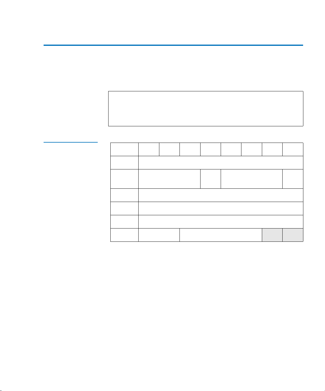
Chapter 2 Emulated Medium Changer SCSI Commands
Release (17h)
Release (17h) 2
The Release command releases the DX-Series system or elements that
match the specified release parameters.
Note: It is not an error to attempt to release the DX-Series system if it
is not currently reserved by the requesting initiator. However,
if the DX-Series system is reserved by another initiator, the
DX-Series system is not released.
Table 48 Release
Command
Bit/Byte 7 6 5 4 3 2 1 0
0
1
2
3
4
5
Logical Unit Number 3rdPty 3rd Party ID
Unused Reserved (00h)
Operation Code (17h)
Reservation ID
Reserved (00h)
Reserved (00h)
Flag (0) Link (0)
• Logical Unit Number
The Logical Unit Number is 0. This field indicates the logical unit to
which the command is sent.
• 3rdPty and 3rd Party ID
The 3rd party release option allows an initiator to release a logical
unit or elements that were previously reserved using the 3rd party
reservation option.
• If the 3rdPty bit is 0, then the 3rd party release option is not
requested and the command only releases a unit or elements that
were reserved without 3rd party reservation
Element
0
Quantum DX-Series Software Interface Guide 71
Page 98

Chapter 2 Emulated Medium Changer SCSI Commands
Release (17h)
• If the 3rdPty bit is 1, the unit or elements released were
originally reserved by the same initiator using the 3rd party
reservation option, and if the device is the same SCSI device that
was specified in the 3rd party device ID (3rd Party ID) field
• Element ID
The Element field specifies whether this command is a Unit Release.
• If the value is 0, the command releases a reservation placed on
this unit by the requesting initiator that meets 3rd party release
requirements, if applicable.
• Reservation ID
If the value is 1, the command releases all elements reserved by the
requesting initiator that were reserved with the same
value as this release attempt and that meet 3rd party release
requirements, if applicable.
•Flag Bit
The Flag bit is used in conjunction with the Link bit to notify the
initiator in an expedient manner that a command has been
completed.
Reservation ID
Flag bits are not supported by the DX-Series system.
•Link Bit
A Link bit set to 1 indicates that the initiator requests continuation of
a task (an I/O process) across two or more SCSI commands.
If the Link bit is 1 and the Flag bit is 0, and the task completes
successfully, the drive continues the task and returns a status of
INTERMEDIATE and a LINKED COMMAND COMPLETE message.
If the Link bit and the Flag bit within a Control word are both set to 1,
and the drive completes a command with a status of
INTERMEDIATE, the drive returns a LINKED COMMAND
COMPLETE message (with Flag).
Link bits are not supported by the DX-Series system.
72 Quantum DX-Series Software Interface Guide
Page 99

Chapter 2 Emulated Medium Changer SCSI Commands
Report LUNS (A0h)
Report LUNS (A0h) 2
The Report LUNS command requests that the peripheral device logical
unit numbers of known logical units in the target be sent to the
applications client. The command only returns information about the
logical units to which commands may be sent.
Table 49 Report
LUNS Command
Bit/Byte 7 6 5 4 3 2 1 0
0
1
2
3-5
(MSB)
6-9
10
11
Operation Code (A0h)
Reserved
Select Report
Reserved
Allocation Length
Reserved
Control
• Allocation Length
If the Allocation Length is not sufficient to contain the logical unit
number values for all configured logical units, the device server still
reports as many logical number values as will fit in the Allocation
Length.
The format of the report of configured logical units is shown in
table 50.
(LSB)
Quantum DX-Series Software Interface Guide 73
Page 100

Chapter 2 Emulated Medium Changer SCSI Commands
Report LUNS (A0h)
Table 50 LUN
Reporting Parameter
List
Bit/Byte 7 6 5 4 3 2 1 0
(MSB)
0-3
4-7
(MSB)
8-15
n-7 - n
LUN List Length (n-7)
(LSB)
Reserved
LUN (first LUN)
(LSB)
.
.
.
LUN (last LUN, if more than one)
The LUN List Length field contains the length in bytes of the LUN list
that can be transferred. The LUN list length equals the number of logical
unit numbers reported multiplied by eight. If the allocation length in the
CDB is too small to allow transfer of information about all of the logical
units configured, the LUN list length value is not adjusted to reflect the
truncation.
74 Quantum DX-Series Software Interface Guide
 Loading...