

Page 1
DPM5500
Quick Start Guide
TABLE OF CONTENTS
Choosing a Location ..........................1
Rack Space Requirements...............1
Environmental Conditions .............1
Preparing for the Installation ...........2
Providing Necessary Tools..............2
Taking ESD Precautions ..................2
Unpacking the DPM5500 ...................2
Installing the DPM5500 System ........2
Locating the Mounting Position ....3
Installing the DPM5500 Chassis .....3
Cabling the DPM5500 ........................5
DPM5500 Default Configuration.......6
DPM5500 Initial Configuration .........6
Microsoft® System Center Data
Protection Manager 2006 ................10
This quick start guides provides basic installation and configuration instructions for
the DPM5500 system. For more information on Microsoft DPM, see http://
www.microsoft.com/windowsserversystem/dpm/default.mspx.
Choosing a Location 0
When choosing an installation site for the DPM5500 system, consider the
following requirements:
• Rack Space Requirements
• Environmental Conditions
Rack Space Requirements 0
Tab l e 1 contains the rack requirements for the DPM5500.
Table 1 Rack Requirements
DPM5500
Depth 25.4 in (64.5 cm)
Width 19 in (48.3 cm)
Height 8.75 in (22.2 cm), 5U
Weight 122 lbs (55.33 kg)
Air Clearance Open 4.0 in (10.2 cm) behind unit for proper air
flow
Environmental Conditions 0
The installation site must have the following environmental conditions:
• Humidity: 20%-80% non-condensing
• Temperature: 10°C-35°C (50°F-95°F)
• Altitude: 0 to 10,000 feet (0 to 3048 meters)
These environmental conditions apply when the DPM5500 system is in operation.
Page 2
DPM5500 Quick Start Guide
Preparing for the Installation 0
Before you begin the installation procedure in this section,
make the following preparations as described in this
section:
• Providing Necessary Tools
• Taking ESD Precautions
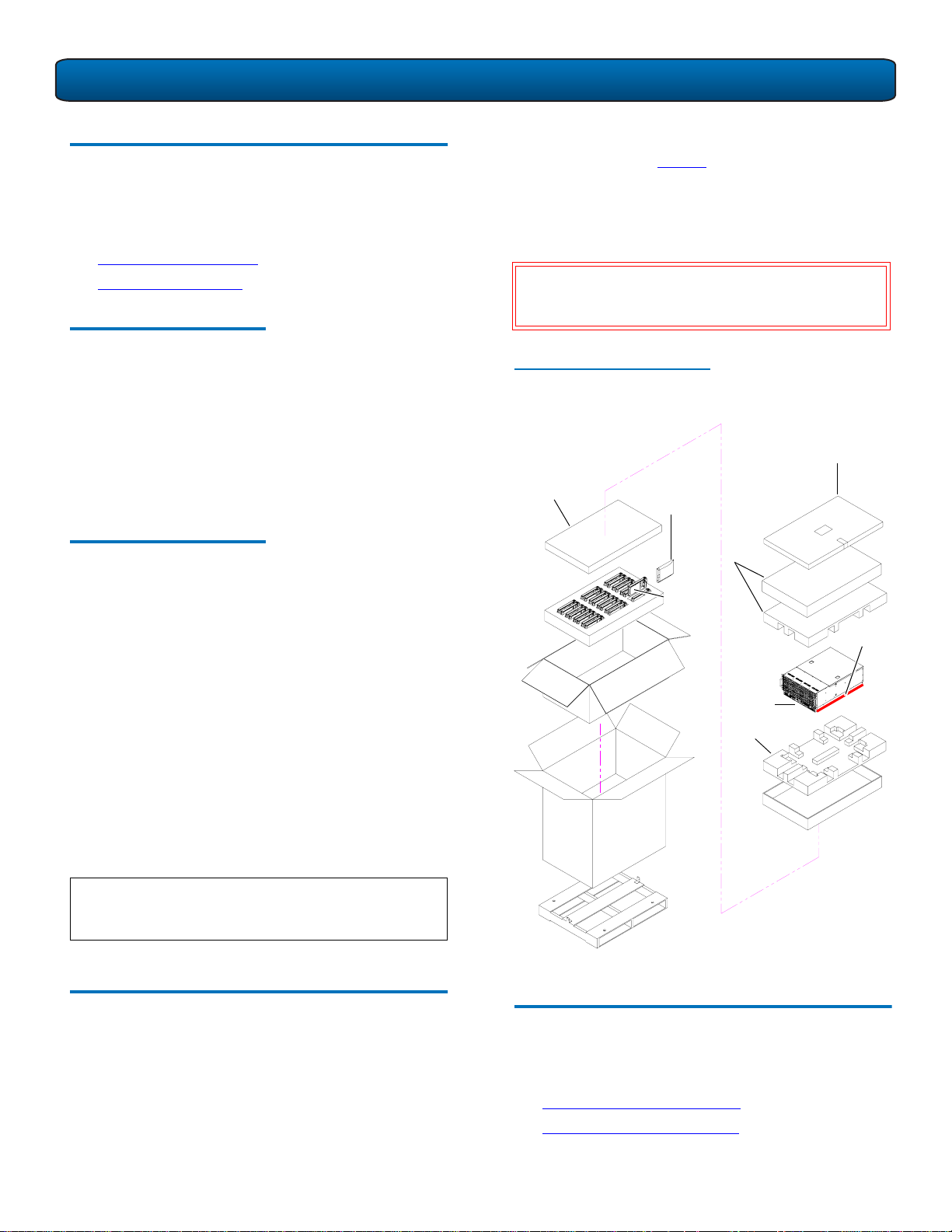
Providing Necessary Tools 0
Unpack and remove the following components from the
packing materials (see figure 1):
• DPM5500 chassis
• Hard drive sleds
• Accessory kit
WARNING: The DPM5500 weights 85 lbs (38.55 kg)
without hard drives. Two people are required
to lift either unit.
Provide the following tools for unpacking and installing the
DPM5500 system:
• #1 PHILLIPS® screwdriver
• #2 PHILLIPS screwdriver
• #1 Flat head screwdriver
• Antistatic wrist strap included in accessory kit
Taking ESD Precautions 0
Some components within the DPM5500 system contain
static-sensitive parts. To avoid damaging these parts while
performing installation procedures, always observe the
following precautions:
• Keep the DPM5500 system turned off during all
installation procedures.
• Use an antistatic wrist strap (included in the accessory
kit).
• Keep static-sensitive parts in their original shipping
containers until ready for installation.
• Do not place static-sensitive parts on a metal surface.
Place them inside their protective shipping bag or on an
antistatic mat.
• Avoid touching connectors and other components.
Figure 1 Unpacking the
DPM5500
Foam
Anti static
bag
Accessory kit
Foam
Hard drive
sleds
Lift point
DPM5500
chassis
Foam
NOTE: Dry climates and cold-weather heating
environments have lower relative humidity and
are more likely to produce static electricity.
Unpacking the DPM5500 0
This section explains how to unpack the DPM5500 system
components and move them to their final installation
location.
By following these instructions, you help ensure that the
system will continue to be safeguarded after it arrives at the
installation site.
Installing the DPM5500 System 0
Installing the DPM5500 in a rack consists of the following
steps:
• Locating the Mounting Position
• Installing the DPM5500 Chassis
2
Page 3
DPM5500 Quick Start Guide
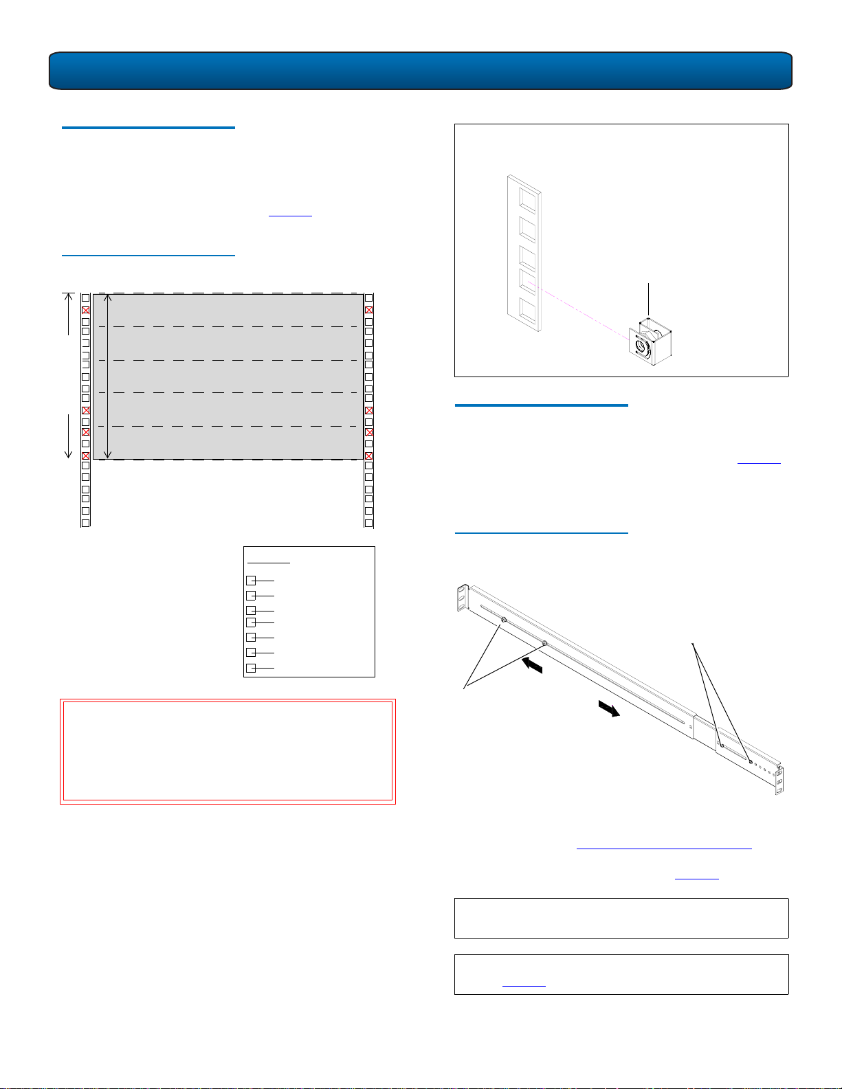
Locating the Mounting
Position 0
The DPM5500 system is designed to fit in a standard 19 inch
wide rack. It is important to the chassis installation to locate
the hole pattern in the rack rails (see figure 2
).
OTE: Quantum ships sufficient clip nuts to support
N
mounting the DPM5500 rack rails and also to
secure the front of the chassis to the rails.
Figure 2 Rail Hole Pattern
5U
5U of rack space
1 DPM5500 System (5U)
The marks above (X)
indicate the location of
mounting hardware on
the rack rails. Ensure that
any necessary mounting
hardware is installed on
the rack rails prior to
installing the chassis.
1U = 1.75 in
(44.45mm)
Hole pattern
Top of rack
.312 in (7.92 mm)
.625 in (15.9 mm)
.625 in (15.9 mm)
.5 in (12.7 mm)
.625 in (15.9 mm)
.625 in (15.9 mm)
.5 in (12.7 mm)
Clip nut
Installing the DPM5500 Chassis 0
1 Assemble the DPM5500 rack rails as shown in figure 3.
You must pull the slide out of the support brackets to
gain access to the mounting holes.
Figure 3 Assembling the Rack
Rails
DPM5500: Front mounting
bracket preset. Ensure the
screws are in the correct
position.
W
ARNING: If the rack is empty at the time of
installation, do NOT install the DPM5500
chassis too high in the rack. The weight of
the chassis may cause the rack to become
“top heavy” and unstable if installed in the
top of an empty rack.
DPM5500: Adjustment
screws; adjusts to the
depth of your rack
2 Install the left and right rack rails at the beginning of a
hole pattern (see Locating the Mounting Position
) and
install two 10-32 x .50 PHILLIPS screws on each rail at
the front and back of the rack (see figure 4
OTE: The support brackets extend to accommodate
N
).
rack depths or 30 to 36 in. (76.2 to 91 cm).
N
OTE: Ensure that clip nuts are installed on the rails (see
figure 2
) prior to installing the DX5000 rails.
3
Page 4

DPM5500 Quick Start Guide
Figure 4 Installing the Chassis
Support Brackets
10-32 x .50
PHILLIPS
screws
DX5000
support
brackets
Clip nuts
Figure 5 DPM5500 Chassis
Mounting Holes
Chassis mounting
holes
Chassis mounting
holes
3 Once the rails are secured to the rack, tighten the rail
adjustment nuts on each rail.
4 With the support brackets installed, prepare the chassis
mounting holes if necessary (see figure 5
for hole
location).
5 Carefully slide the storage array into the rack.
W
ARNING: The DPM5500 weights 85 lbs (38.55 kg).
Two people are required to lift the unit.
6 Secure the DPM5500 chassis to the rack with two 10-32
x 1.25 in. (M5 x 32 metric also provided) black PHILLIPS
screws on each side of the front of the chassis. Tighten
to 5 in/oz. (see figure 6).
4
Page 5
DPM5500 Quick Start Guide
Figure 6 Securing the DPM5500
Chassis to the Rack
DPM5500 chassis
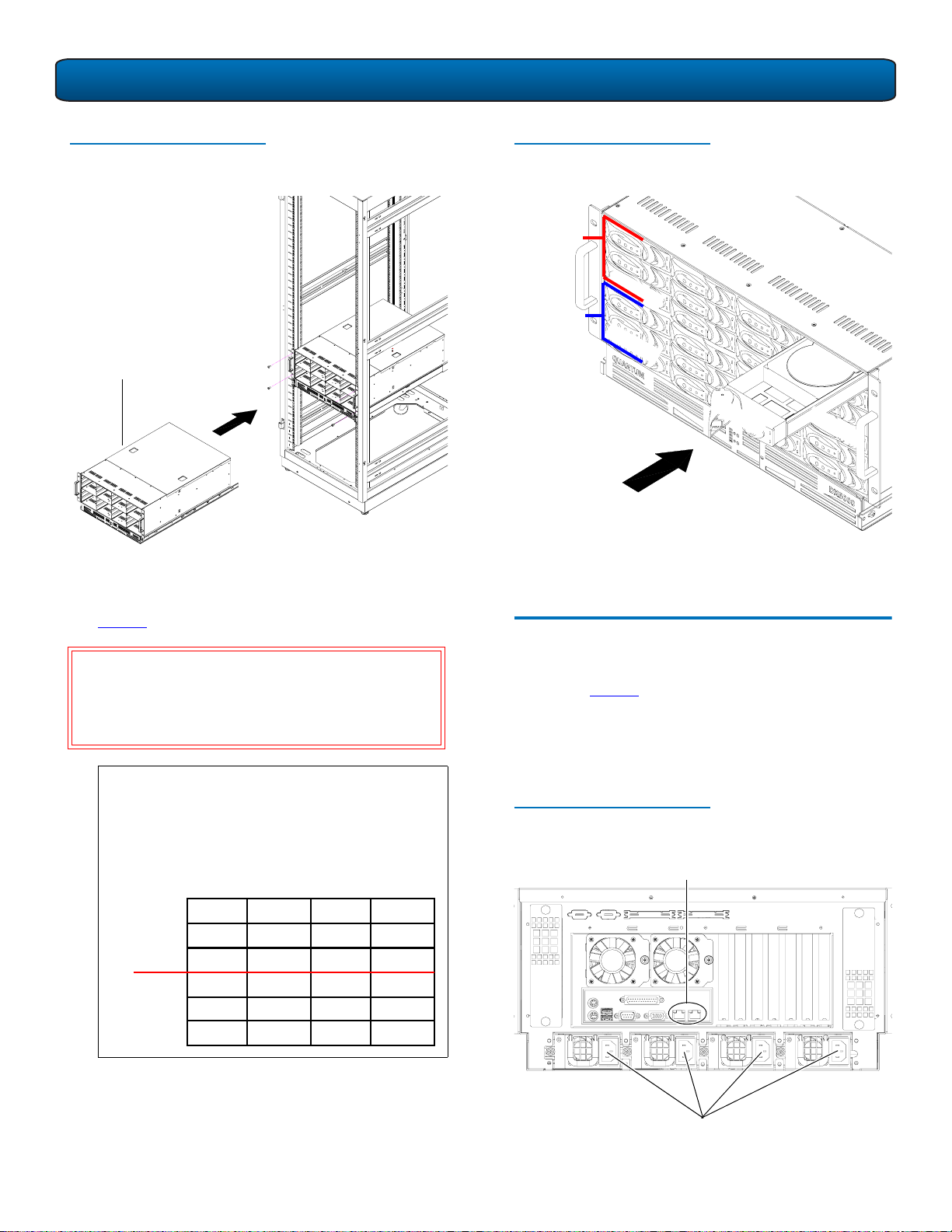
7 Install each of the hard drive sleds into the DPM5500
chassis. Ensure each drive is completely installed in the
chassis with the drive handle in the closed position (see
figure 7
).
Figure 7 Installing the Disk
Drives in the DPM5500 Chassis
Array
controller 2
D
r
i
v
e
Array
controller 1
0
D
r
i
v
e
0
D
r
i
v
e
1
1
D
r
i
v
e
1
1
The DPM5500 chassis is now installed in the rack.
Cabling the DPM5500 0
CAUTION: Use ESD procedures when handling the hard
drives sleds (see “Taking ESD Precautions” on
page 2). Place the ESD wrist strap on your
wrist and connect the other end of the strap
to the DPM5500 chassis.
OTE: The hard drives must be installed in the
N
proper sequence since RAID sets have already
been established at the factory. Refer to the
label on the bottom of the drive sled for the
drive number. The hard drives must also be
installed in the array in which it was
configured.
Array
controller 2
Array
controller 1
DPM5500
Drive 8 Drive 9 Drive 10 Drive 11
Drive 4 Drive 5 Drive 6 Drive 7
Drive 0 Drive 1 Drive 2 Drive 3
Drive 8 Drive 9 Drive 10 Drive 11
Drive 4 Drive 5 Drive 6 Drive 7
Drive 0 Drive 1 Drive 2 Drive 3
Connect the following cables to the back of the DPM5500
system (see figure 8):
• Connect a power cable to each power supply
• Connect an Ethernet cable to ports ETH1 to connect the
DPM5500 to the local area network (LAN).
Figure 8 DPM5500 System
Cabling
Ethernet cables (ports 1 and 2)
1 2
Power supply cables
5
Page 6

DPM5500 Quick Start Guide
DPM5500 Default Configuration 0
The DPM5500 is configured from Quantum with Microsoft
Windows Server 2003 and Data Protection Manager loaded
on the device. The DPM5500 contains a system
motherboard, processor, and a SCSI HBA. Refer to the
following username and password to access the system:
Username: administrator
Password: Quantum-DPM
OTE: The password is case sensitive.
N
N
OTE: It is recommended to join a test domain within
Windows
The storage array portion of the DPM5500 system contains
12, 18, or 24 hard drives and is used as the primary storage
area of the DPM5500. The DPM application, SQL DPM
database, and the Windows 2003 operating system are
located on 2 internal mirrored hard drives. The DPM5500 is
formatted from Quantum with the following partition:
• 37 GB Partitions
• Storage Area
37 GB Partitions
The operating system hard drives contain a single 37 GB
partition. This partition contains the Windows Server 2003
operating system which serves as the boot partition. This
partition also contains the DPM application software and
DPM application database.
DPM5500 Initial Configuration 0
To initially configure the DPM5500 and prepare for
operation:
N
OTE: A domain server must be setup and on the same
network as the DPM5500 before continuing with
this procedure.
0
NOTE: It is highly recommended that the system
administrator with access to the DHCP server be
0
0
available during this initial configuration of the
DPM5500. The IP address assigned to the
DPM5500 must available to access the system.
1 Turn on the DPM5500 system by pressing the power
button located on the front of the chassis.
2 The DPM5500 uses DHCP (Dynamic Host Configuration
Protocol) to receive an IP address from a local DHCP
server. You will need this IP address to access the
DPM5500. Write the IP address in the space provided
below:
DPM5500 IP Address:___________________________
Example: https://<ip address>:8098
OTE: This IP address uses https, not the common
N
http and there is also a special port (8098)
that must be used. This address must be used
every time the web pages are accessed.
3 Enter the IP address assigned to the DPM5500 into a
web browser to access the DPM5500 configuration
wizard.
The DPM5500 configuration wizard displays (see
figure 9
).
Storage Area
The storage area contains a 4.8 TB, 7.2 TB, or 9.6 TB
(approx.) partition for use as storage space for the DPM
software. This partition is only used by DPM and is not
accessible from the Windows Server 2003 operating system.
Microsoft® DPM 0
The Microsoft® DPM application software is installed on the
system, however, the software is not initially configured.
Refer to the Microsoft DPM documentation for information
on DPM configuration.
0
6
Page 7

DPM5500 Quick Start Guide
Figure 9 Accessing the DPM5500
Start
wizard link
4 Click the Start Wizard link to continue the configuration
wizard.
The Welcome screen displays (see figure 10
).
Figure 10 Welcome Screen
Figure 11 License Agreement
6 You must select I agree with the Terms specified in
the EULA for all three license agreements to continue
with the DPM5500 configuration. Click Next to
continue.
NOTE: If you click Cancel, the system will shutdown
and you will have to turn the DPM5500 on by
pressing the power button on the front of
the chassis.
Next
5 Click Next.
The License Agreement screen displays (see figure 11
The IP Address Configuration screen displays (see
figure 12
).
Figure 12 IP Address
Configuration
).
7
Page 8

DPM5500 Quick Start Guide
7 The DPM5500 system is configured by default to accept
IP addresses from a DHCP server. If you need to change
the IP Address, select Use the following IP settings
and enter the network information. One of the LAN
settings must be configured for the domain server.
OTE: Local Area Connection and Local Area
N
Connection 2 correspond to Ethernet ports 1
and 2 located on the back of the DPM5500
chassis.
When you have finished configuring the local area
connection settings, click Next to continue. The
DPM5500 reboots.
OTE: If the network settings were unchanged, the
N
DPM5500 will not reboot. Continue with the
next step.
The system takes several minutes to reboot.
8 Re-enter the DPM5500 IP address in the web browser
to access the configuration wizard.
9 Click the Start Wizard link to continue the
configuration wizard.
The Date and Time Configuration screen displays (see
figure 13
).
Figure 13 Date and Time
Configuration
Figure 14 Server Identity
Configuration
11 Enter the following server identity information:
• Server name or accept the system generated server
name. This name must be unique from any other
DPM5500 systems on the same network.
• Domain name, user, and password information.
This allows the DPM5500 to access the domain
server.
12 Click Next to continue. The DPM5500 reboots. The
system takes several minutes to reboot.
NOTE: If you receive a security warning from
Windows, click Yes to continue.
10 Enter the date and time information and click Next to
continue.
The Server Identity screen displays (see figure 14
).
13 Re-enter the DPM5500 IP address in the web browser
to access the configuration wizard.
The system prompts you to log in.
14 Enter Administrator for the user name and Quantum-
DPM for the password.
NOTE: The password is case sensitive.
The Server Setup Wizard displays.
15 Click the Start Wizard link to continue the
configuration wizard.
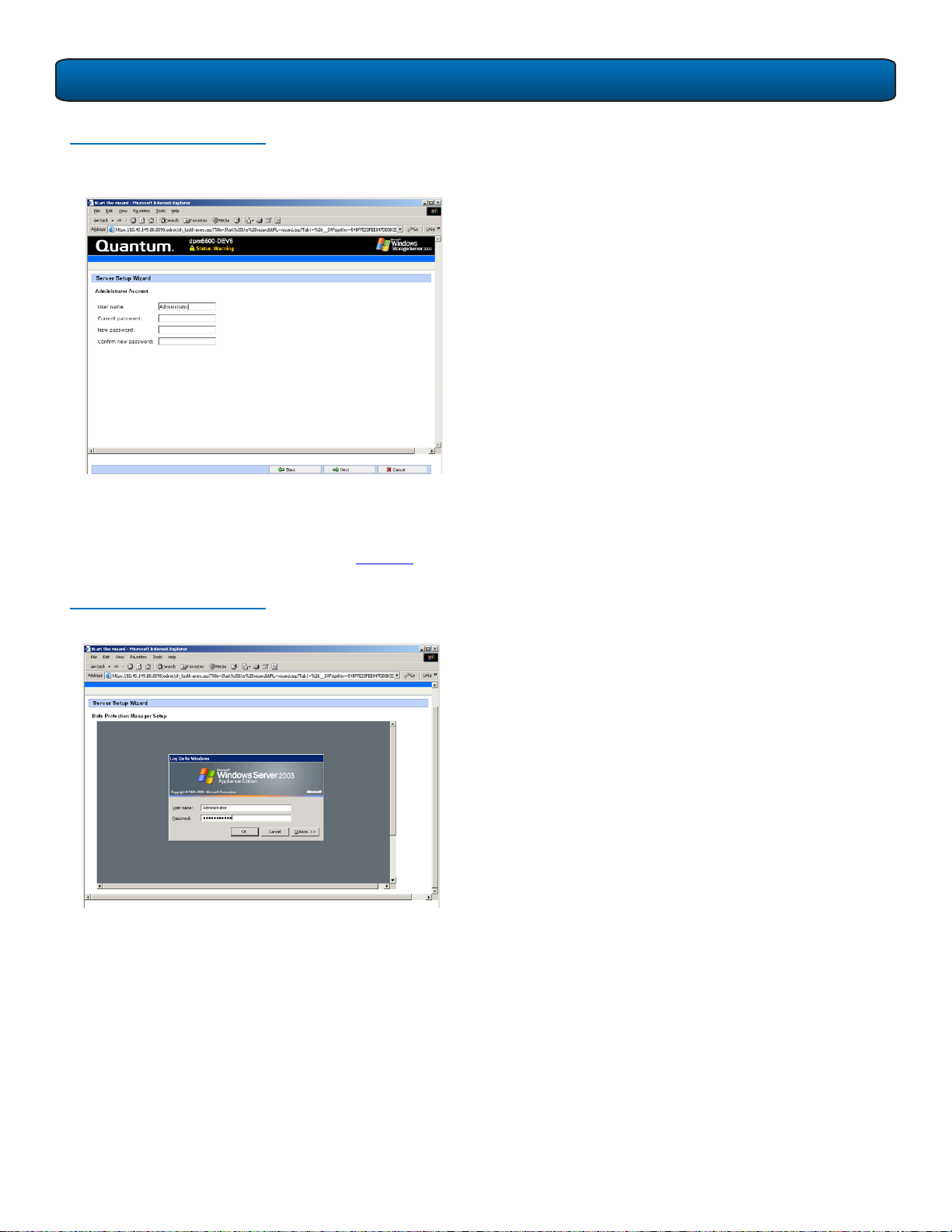
The Administrator Account screen displays (see
figure 15
).
8
Page 9
DPM5500 Quick Start Guide
Figure 15 Administrator Account
Configuration
16 Enter the administrator information and click Next to
continue. This information is used to log into the
DPM5500.
The DPM Remote Desktop displays (see figure 16
).
Figure 16 DPM Remote Desktop
17 Enter your username and password to login.
18 Configure DPM per the Microsoft® documentation.
When completed, click Next to continue.
The Finished Setup screen displays.
The DPM5500 is initially configured and ready for
operation. Refer to the Microsoft® documentation for
information on configuring the Microsoft® System
Center Data Protection Manager.
9
Page 10

DPM5500 Quick Start Guide
Microsoft® System Center Data Protection Manager 2006 0
Microsoft® System Center Data Protection Manager 2006
(DPM) is a server software application that enables diskbased data protection and recovery for file servers in an
Active Directory® domain. DPM performs replication,
synchronization, and shadow copy creation to provide
reliable protection and rapid recovery of data for both
system administrators and end-users.
For more information on Microsoft DPM, see http://
www.microsoft.com/windowsserversystem/dpm/
default.mspx.
United States of America
Quantum Corporation
141 Innovation Drive
Irvine, CA 92612
U.S.A.
phone 949.856.7800
fax 949.856.7799
©2006 Quantum Corporation. Quantum, the Quantum logo, and the DLTtape logo are all registered trademarks of Quantum Corporation. SDLT and Super DLTtape are trademarks of
Quantum Corporation. Other trademarks may be mentioned herein which belong to other companies.
European Headquarters
Quantum Corporaton
3 Bracknell Beeches
Old Bracknell Lane West
Bracknell
Berkshire RG12 7BW
United Kingdom
phone +44 1344 353500
fax +44 1344 353510
Asia Pacific
Quantum Corporaton
9 Temasek Boulevard, #08-03
Suntec Tower Two
Singapore 038989
Tel: +65 6334 0660
Fax: +65 6432 2830
Email: singapore.sales@quantum.com
81-81514-02 A01 February 2006
 Loading...