

Page 1

ATL StackLink™
Installation Instructions
6421009-07 A01
Page 2

Quantum ATL StackLink™ Installation Instructions, 6421009-07 A01, September 2003, Made in USA.
Quantum Corporation provides this publication “as is” without warranty of any kind, either express or
implied, including but not limited to the implied warranties of merchantability or fitness for a particular
purpose. Quantum Corporation may revise this publication from time to time without notice.
COPYRIGHT STATEMENT
Copyright 2003 by Quantum Corporation. All rights reserved.
Your right to copy this manual is limited by copyright law. Making copies or adaptations without prior
written authorization of Quantum Corporation is prohibited by law and constitutes a punishable violation of
the law.
TRADEMARK STATEMENT
Prism Library Architecture, IntelliGrip, StackLink, WebAdmin, and WebLibrarian are all trademarks of
Quantum Corporation.
Other trademarks may be mentioned herein which belong to other companies.
6207947-06cP 63
Page 3

Contents
Preface xiii
Chapter 1 Installing the StackLink 1
Preparing for the StackLink Installation......................................................... 1
StackLink Kit Contents .............................................................................. 2
Required Tools ............................................................................................ 3
Preparing the Rack ..................................................................................... 4
Installing the Top Mounting Tray Assembly................................................. 7
Installing the Bottom Mounting Tray Assembly........................................... 9
Installing the Carriage/Counterweight Assembly ..................................... 11
Installing the Motor Assembly....................................................................... 15
Attaching the Shuttle Assembly to the Mounting Tray Assemblies ........17
Chapter 2 Installing the Rack Mount Shelves 19
Determining the Position of the Shelves in the Rack..................................20
Installing the Shelves....................................................................................... 22
Installing the ATL M1500 Rack Mount Shelves ................................... 22
Installing the ATL M2500 Rack Mount Shelves ................................... 30
ATL StackLink™ Installation Instructions iii
Page 4

Contents
Chapter 3 Installing the Libraries 47
Installing the Libraries in the Rack ................................................................48
Installing Tape Drives in the Libraries..........................................................50
Installing Tape Drives in an ATL M1500...............................................51
Installing Tape Drives in an ATL M2500...............................................52
Installing the Safety Blanking Panels ............................................................54
Preparing and Inserting Tape Cartridges .....................................................55
Labeling Tape Cartridges.........................................................................56
Setting the Write-Protect Switch.............................................................57
Placing Cartridges in the Library............................................................59
Chapter 4 Cabling the Multiple Library Stack 65
Interlibrary (Control Bus) Cabling................................................................. 66
StackLink Motor Connection..........................................................................68
SCSI Bus Cabling..............................................................................................70
SCSI Cabling Guidelines ..........................................................................72
Terminator Power .....................................................................................72
Power Cabling...................................................................................................72
Connecting an ATL M1500 Library to AC Power ................................73
Connecting an ATL M2500 Library to AC Power ................................75
Chapter 5 Completing the Installation 79
Powering Up the Library ................................................................................79
Disabling Unused Drive Bays.........................................................................82
Configuring the Library ..................................................................................84
SCSI Import/Export Elements ................................................................85
Tape Drive SCSI IDs .................................................................................85
Library SCSI Settings................................................................................85
Testing the Library Robotics...........................................................................86
Appendix A Library Size 89
Library Size .......................................................................................................89
Library Size Calculation Examples................................................................90
Library Size in Mixed Stacks...........................................................................92
iv ATL StackLink™ Installation Instructions
Page 5

Contents
Appendix B SCSI Element Addressing 95
Overview........................................................................................................... 95
Option Settings and Their Effect on SCSI Element Addressing ............... 98
Auto-Clean Option ................................................................................... 98
Import/Export Option............................................................................. 98
SCSI Element Addressing in Multiple Library Stacks.............................. 103
ATL StackLink™ Installation Instructions v
Page 6

Contents
vi ATL StackLink™ Installation Instructions
Page 7

Figures
Figure 1 Inserting Caged Nuts into the Rack Rails................................. 5
Figure 2 Caged Nut Locations ...................................................................6
Figure 3 Adjusting the Depth of the Top Mounting Tray Assembly ... 7
Figure 4 Securing the Top Mounting Tray Assembly to the Rack........ 8
Figure 5 Adjusting the Depth of the Bottom Mounting Tray
Assembly ....................................................................................... 9
Figure 6 Securing the Bottom Mounting Tray Assembly to
the Rack........................................................................................ 10
Figure 7 Installing the Carriage/Counterweight Assembly ............... 12
Figure 8 Connecting the Umbilical Cable to the Bottom of the
Carriage........................................................................................ 14
Figure 9 Inserting the Motor Assembly into the Vertical
Shuttle Assembly........................................................................ 15
Figure 10 Securing the Motor Assembly to the Vertical
Shuttle Assembly........................................................................ 16
Figure 11 Routing the Belt .......................................................................... 16
Figure 12 Connecting the Ribbon Cable ................................................... 17
Figure 13 Installing the Shuttle Assembly................................................ 18
Figure 14 Example of Full and Half U Mounting Positions .................. 21
ATL StackLink™ Installation Instructions vii
Page 8

Figures
Figure 15 Identifying the Shelf Extender Slots.........................................25
Figure 16 Attaching the Shelves to the Extenders...................................26
Figure 17 Installing the Inserts in the Shelves..........................................27
Figure 18 Installing the Shelf in the Rack .................................................28
Figure 19 Securing the Shelf Clamp to the Rail .......................................29
Figure 20 Identifying the Shelf Extender Slots.........................................32
Figure 21 Attaching the Shelves to the Extenders...................................33
Figure 22 Installing Inserts at the Front of the Shelves...........................34
Figure 23 Installing Inserts at the Rear of the Shelves ............................35
Figure 24 Installing the Shelves..................................................................35
Figure 25 Installing the Front Shelf Clamps.............................................36
Figure 26 Installing the Rear Shelf Clamps ..............................................37
Figure 27 Installing the Clamp Strips........................................................39
Figure 28 Installing Inserts at the Front of the Shelves...........................41
Figure 29 Installing Inserts at the Rear of the Shelves ............................41
Figure 30 Installing the Shelves..................................................................42
Figure 31 Installing the Front Shelf Clamps.............................................43
Figure 32 Installing the Rear Shelf Clamps ..............................................44
Figure 33 Installing the Clamp Strips........................................................45
Figure 34 Rack Mount Clamp Screw Access Holes, ATL M1500.......... 49
Figure 35 Rack Mount Clamp Screw Access Holes, ATL M2500.......... 49
Figure 36 Installing a Tape Drive in an ATL M1500 Library.................51
Figure 37 Drive Bay Numbering, ATL M2500.........................................52
Figure 38 Installing a Tape Drive in an ATL M2500 Library.................53
Figure 39 Labeling Tape Cartridges ..........................................................57
Figure 40 Setting the Write-Protect Switch (DLT and
SDLT Cartridges) ........................................................................58
Figure 41 Setting the Write-Protect Switch (LTO Cartridges) ...............58
Figure 42 Magazine Release Button...........................................................59
Figure 43 Inserting DLT Cartridges into a Magazine .............................60
viii ATL StackLink™ Installation Instructions
Page 9

Figures
Figure 44 Removing the Level 2 Left Magazine......................................61
Figure 45 Release Latch............................................................................... 62
Figure 46 Removing the Level 1 Left Magazine......................................62
Figure 47 Library Control and StackLink Power Cabling ..................... 67
Figure 48 StackLink Motor Connection.................................................... 69
Figure 49 Typical SCSI Bus Connections.................................................. 71
Figure 50 Power Inlet .................................................................................. 73
Figure 51 Power Inlet .................................................................................. 76
Figure 52 Power Switch, ATL M1500........................................................ 80
Figure 53 Power Switches, ATL M2500....................................................80
Figure 54 Welcome Screen, ATL M2500................................................... 81
Figure 55 Main Screen, ATL M2500 .......................................................... 81
Figure 56 Using the GUI Buttons............................................................... 82
Figure 57 Menu Screen................................................................................ 83
Figure 58 Configuration Screen ................................................................. 83
Figure 59 Menu Screen................................................................................ 86
Figure 60 Demo Programs Screen .............................................................87
Figure 61 Main Screen................................................................................. 89
Figure 62 Library Size Calculation Examples.......................................... 91
Figure 63 Library Size Calculation, ATL M1500 Stack vs.
Mixed Stack .................................................................................93
ATL StackLink™ Installation Instructions ix
Page 10

Figures
x ATL StackLink™ Installation Instructions
Page 11

Tables
Table 1 Contents, StackLink Kit ............................................................... 2
Table 2 Contents, ATL M1500 Universal Rack Mount Kit................. 23
Table 3 Shelf Assembly Matrix............................................................... 25
Table 4 Contents, ATL M2500 Universal Rack Mount Kit................. 30
Table 5 Shelf Assembly Matrix............................................................... 32
Table 6 Bar Code Label Requirements .................................................. 56
Table 7 ATL M1500 AC Distribution Requirements........................... 74
Table 8 ATL M2500 AC Distribution Unit Requirements.................. 76
Table 9 SCSI Element Addressing, Stand-alone ATL M1500 ............ 96
Table 10 SCSI Element Addressing, Stand-alone ATL M2500 ............ 96
Table 11 ATL M1500, Import/Export Option Set to 1-Slot.................. 99
Table 15 Element Addressing, Multiple Library Stack....................... 103
Table 16 Element Addressing, Multiple Library Stack....................... 105
ATL StackLink™ Installation Instructions xi
Page 12

Tables
xii ATL StackLink™ Installation Instructions
Page 13

Preface
This document explains how to install the StackLink™ mechanism. The
StackLink provides the physical connection between library modules in a
multiple library stack, allowing each of the tape drives in the stack to
have access to all of the data cartridges.
Four heights of StackLink can be purchased for use with the
ATL M-Series libraries: 10U, 22U, 30U, and 42U.
Audience This document is written for installers of the StackLink mechanism.
Purpose This document explains how to install a multiple library stack, including:
• Installing the StackLink mechanism
• Installing the rack mount shelves
• Installing the library modules in the rack
• Installing tape drives in the library modules
• Installing safety blanking panels
• Preparing and inserting tape cartridges
• Cabling the multiple library stack
ATL StackLink™ Installation Instructions xiii
Page 14

Preface
Document
Organization
Notational
Conventions
This document is organized as follows:
• Chapter 1, Installing the StackLink
, explains how to install the
StackLink mechanism in the rack.
• Chapter 2, Installing the Rack Mount Shelves
, explains how to install
the rack mount shelves.
• Chapter 3, Installing the Libraries
, explains how to install the libraries
in the rack, install tape drives in the libraries, install the safety
blanking panels, and prepare and insert tape cartridges.
• Chapter 4, Cabling the Multiple Library Stack
, explains how to
connect the interlibrary (control bus), StackLink, SCSI bus, and power
cabling.
• Chapter 5, Completing the Installation
, explains how to power up the
multiple library stack, disable unused drive bays, configure the
library, and test the library robotics.
• Appendix A, Library Size
, explains how the library firmware
calculates and reports library size.
• Appendix B, SCSI Element Addressing
, explains how the library
firmware assigns SCSI element addresses.
This manual uses the following conventions:
Note: Notes emphasize important information related to the main
topic.
Caution: Cautions indicate potential hazards to equipment and are
included to prevent damage to equipment.
Warning: Warnings indicate potential hazards to personal safety and
are included to prevent injury.
xiv ATL StackLink™ Installation Instructions
Page 15

Preface
Related
Documents
Documents related to the ATL M-Series libraries are shown below.
ATL M-Series Documentation
Doc. No Title Description
6421001 ATL M1500 Field
Service Manual
This document explains how to
service the ATL M1500 library,
including:
• Understanding error codes
• Using built-in diagnostic checks
to troubleshoot library problems
• Replacing field replaceable
units (FRUs)
6421002 ATL M1500
Unpacking
Instructions
6421005 ATL M1500 Rack
Mount to Desktop
Conversion
Instructions
This document explains how to
remove the ATL M1500 library
from its shipping container.
This document explains how to
convert a rack mounted
ATL M1500 library to a desktop
unit.
0
6421007 ATL M1500 Desktop to
Rack Mount
Conversion
This document explains how to
convert a desktop ATL M1500
library to a rack mount unit.
Instructions
6421008 ATL M-Series Tape
Drive Installation
Instructions
6421010 ATL M-Series Software
Interface Guide
This document explains how to
install a tape drive in an ATL
M-Series library.
This document describes the
procedures and issues involved in
the development of hierarchical
mass storage software applications
and utilities to communicate with
the ATL M-Series libraries.
ATL StackLink™ Installation Instructions xv
Page 16

Preface
Doc. No Title Description
6421014 ATL M-Series Tape
Drive Removal and
Replacement
Instructions
6421015 ATL M1500 Chassis
Removal and
Replacement
Instructions
6421017 ATL M1500 Chassis
Unpacking
Instructions
6421026 ATL M1500 Spacer
Installation
Instructions
6421034 ATL M1500 Front
Bezel/GUI Assembly
Replacement
Instructions
This document explains how to
remove and replace a tape drive in
an ATL M-Series library.
This document explains how to
remove, package for shipment,
and replace an ATL M1500 library
chassis.
This document explains how to
unpack the ATL M1500 library
chassis FRU.
This document explains how to
install spacers on the rack before
installing an M1500 library. These
spacers are necessary if you are
installing a new M1500 library in a
rack with older M1500 libraries
and a StackLink mechanism.
This document describes the
procedure for replacing the front
bezel/graphical user interface
(GUI) assembly in an ATL M1500
library.
6423000 ATL M2500
Unpacking
Instructions
6423001 ATL M-Series
Installation Guide
6423002 ATL M-Series User’s
Guide
xvi ATL StackLink™ Installation Instructions
This document explains how to
remove the ATL M2500 library
from its shipping container.
This document explains how to
install an ATL M-Series library.
This document explains how to
operate an ATL M-Series library.
Page 17

Doc. No Title Description
Preface
6423003 ATL M2500 Field
Service Manual
6423006 ATL M-Series Library
Redundant Power
Supply Replacement
Instructions
6423007 ATL M-Series Library
Universal Power
Supply Replacement
Instructions
6423008 ATL M-Series Library
System Board PWA
Replacement
Instructions
This document explains how to
service the ATL M2500 library,
including:
• Understanding error codes
• Using built-in diagnostic checks
to troubleshoot library problems
• Replacing field replaceable
units (FRUs)
This document explains how to
remove and replace a redundant
power supply in an ATL M-Series
library
This document explains how to
remove and replace a universal
power supply in an ATL M-Series
library.
This document explains how to
remove and replace the system
board PWA in an ATL M-Series
library.
6423009 ATL M-Series Library
SCSI Servo Board and
SCSI Adapter
Replacement
This document explains how to
remove and replace the SCSI servo
board and SCSI adapter in an
ATL M-Series library.
Instructions
6423010 ATL M-Series Library
Robotic Hand Removal
and Replacement
This document explains how to
remove and replace the robotic
hand in an ATL M-Series library.
Instructions
6423012 ATL M2500 Library
GUI Assembly
Replacement
This document explains how to
remove and replace the GUI
assembly in an ATL M2500 library.
Instructions
ATL StackLink™ Installation Instructions xvii
Page 18

Preface
Doc. No Title Description
6423034 Quantum ATL
M-Series Power Supply
Upgrade Instructions
6423036 ATL M2500 Rack
Mount to Deskside
Conversion
Instructions
6423039 Quantum ATL
StackLink FRU
Removal and
Replacement
Instructions
6423062 Quantum ATL
M-Series Drive Brick
Replacement
Instructions
6423063 Quantum ATL M2500
Bezel/Doors/Winged
Window Replacement
Instructions
This document explains how to
upgrade the power supply in an
ATL M-Series library.
This document explains how to
convert a rack mounted ATL
M2500 to a deskside library.
This document explains how to
remove and replace the StackLink
motor assembly, carriage,
counterweight, and umbilical
chain.
This document explains how to
remove and replace an SDLT 320,
SDLT 600, or HP LTO Gen 2 tape
drive (without a canister) in an
ATL M-Series library.
This document explains how to
replace the bezel, doors, and
window in an ATL M2500 library.
Refer to the appropriate product manuals for information about your
tape drive and cartridges.
SCSI-2 Specification
The SCSI-2 communications specification is the proposed American
National Standard for information systems, dated March 9, 1990. Copies
may be obtained from:
Global Engineering Documents
15 Inverness Way, East
Englewood, CO 80112
(800) 854-7179 or (303) 397-2740
xviii ATL StackLink™ Installation Instructions
0
Page 19

Contacts Quantum company contacts are listed below.
Preface
Quantum Corporate Headquarters
To order documentation on the ATL M-Series libraries or other products
contact:
Quantum Corporation
P.O. Box 57100
Irvine, CA 92619-7100
(949) 856-7800
(800) 284-5101
Technical Publications
To comment on existing documentation send e-mail to:
doc-comments@quantum.com
Quantum Home Page 0
Visit the Quantum home page at:
http://www.quantum.com
0
0
Customer Support 0
The Quantum Customer Support Department provides a 24-hour help
desk that can be reached at:
North/South America: (949) 725-2100 or
(800) 284-5101
Asia/Pacific Rim: (International Code)
+61 7 3839 0988
Europe/Middle East/Africa: (International Code)
+44 (0) 1256 848748
ATL StackLink™ Installation Instructions xix
Page 20

Preface
Send faxes for the Customer Support Department to:
North/South America: (949) 725-2176
Asia/Pacific Rim: (International Code)
+61 7 3839 0955
Europe/Middle East/Africa: (International Code) +
+44 (0) 1256 848777
Send e-mail for the Customer Support Department to:
North/South America: Go to http://www.quantum.com/
askaquestion and enter your question
and e-mail address
Asia/Pacific Rim: apachelp@quantum.com
Europe/Middle East/Africa: ukhelpdesk@quantum.com
xx ATL StackLink™ Installation Instructions
Page 21

Chapter 1
1Installing the StackLink
The StackLink installation procedure consists of the following steps:
• Preparing for the StackLink Installation
• Installing the Top Mounting Tray Assembly
• Installing the Bottom Mounting Tray Assembly
• Installing the Carriage/Counterweight Assembly
• Installing the Motor Assembly
• Attaching the Shuttle Assembly to the Mounting Tray Assemblies
Preparing for the StackLink Installation 1
Before starting the StackLink installation procedure:
• Verify that the StackLink kit contains all of the necessary items (see
the following section, StackLink Kit Contents
• Make sure you have the necessary tools for the installation (see
Required Tools
• Prepare the rack for the installation (see Preparing the Rack
ATL StackLink™ Installation Instructions 1
).
).
).
Page 22
Chapter 1 Installing the StackLink
Preparing for the StackLink Installation
StackLink Kit Contents
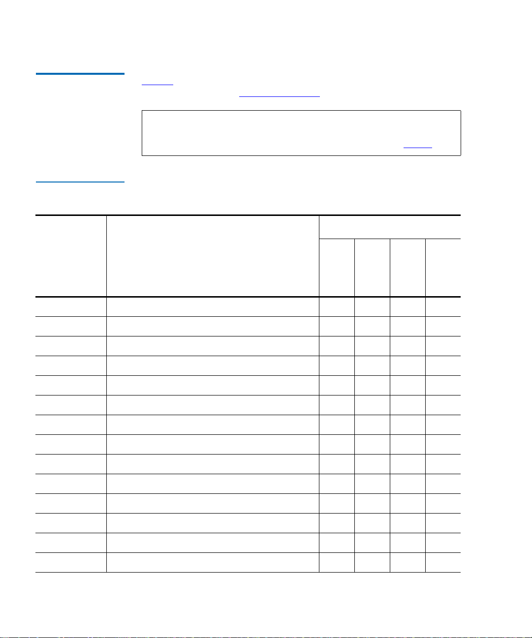
Table 1 lists the contents of the StackLink kit. If any items are missing,
contact Quantum (see Customer Support
1
on page xix).
Note: The StackLink kit is shipped in two boxes. Before starting the
installation procedure, verify that you received both boxes,
and that the boxes contain all of the items listed in table 1
Table 1 Contents,
StackLink Kit
Quantity Provided
Part No. Description
with 10U
StackLink
with 22U
StackLink
212406 Front safety blanking panel, 1U N/A 1 1 1
212407 Front safety blanking panel, 2U N/A 1 1 1
212502 Rear safety blanking panel, 4U N/A 3 5 8
212579 Front safety blanking panel, 4U N/A 3 5 8
with 30U
StackLink
.
with 42U
StackLink
214217 Rear safety blanking panel, .5U N/A 1 1 1
214218 Rear safety blanking panel, 1U N/A 2 2 2
215941 Front panel, .5U N/A 1 1 1
6421009 ATL StackLink Installation Instructions 1111
214070 StackLink motor cable (2 meter) N/A N/A 1 1
214080 StackLink motor cable (1 meter) N/A 1 N/A N/A
214090 StackLink motor cable (.6 meter) 1 N/A N/A N/A
214370 Top mounting tray assembly 1111
214380 Bottom mounting tray assembly 1111
214390 Vertical shuttle assembly (10U) 1 N/A N/A N/A
2 ATL StackLink™ Installation Instructions
Page 23

Chapter 1 Installing the StackLink
Preparing for the StackLink Installation
Quantity Provided
Part No. Description
with 10U
StackLink
with 22U
StackLink
with 30U
StackLink
with 42U
214400 Vertical shuttle assembly (22U) N/A 1 N/A N/A
214410 Vertical shuttle assembly (42U) N/A N/A N/A 1
214450 Shuttle motor mount assembly 1111
215180 Carriage/counterweight assembly 1111
217370 Vertical shuttle assembly (30U) N/A N/A 1 N/A
AS3642 Library control bus cable (.5 meter) 3 5 7 10
AS3643 Library control bus cable (2 meter) N/A 1 1 1
AS3667 Library control bus cable (1 meter) N/A 1 1 2
YS40402M4 plain washer 6666
YS40404 M6 plain washer 16 22 26 32
YS41731 Washer, large N/A 6 6 6
YS41952M4 x 12 socket head cap screw 6666
YS41964 M4 x 10 socket head cap screw 1 7 11 17
YS42008 M6 caged nut 16 22 26 32
StackLink
YS42011 M6 x 12 button head screw 16 22 26 32
YS42038M4 x 10 socket head countersink screw 2222
Required Tools 1
The following tools are required to install the StackLink:
• Flat blade screwdriver
•No. 2 POZIDRIV
•Metric Allen
ATL StackLink™ Installation Instructions 3
®
screwdriver
®
wrenches, sizes M4 and M6
Page 24

Chapter 1 Installing the StackLink
Preparing for the StackLink Installation
Preparing the Rack
To prepare the rack for the installation procedure:
1
1 Verify that the distance between the front and rear mounting strips is
between 19 inches and 36 inches (483 mm and 914 mm). If this is not
the case, adjusting the mounting strips referring to the instructions
provided by the rack manufacturer.
2 Determine the correct placement of the StackLink in the rack.
Caution: Take rack stability into account when determining
where to place the StackLink. If the multiple library
stack will be the only equipment in the rack, it is
recommended that you install the StackLink at the
bottom of the rack.
The bottom mounting tray assembly should be installed at the
bottom of the rack.
Note: The bottom mounting tray assembly occupies 1U of rack
space unless you are installing 3 ATL M2500 libraries in
the rack. In this configuration, the bottom mounting tray
assembly is modified to occupy .5U of rack space.
Note: 1U equals 1.75 inches, or 44 millimeters.
The top mounting tray assembly should be installed as follows:
• If you are installing an 10U StackLink, allow 8U of space between
the top and bottom mounting tray assemblies.
• If you are installing a 22U StackLink, allow 20U of space between
the top and bottom mounting tray assemblies.
• If you are installing a 30U StackLink, allow 28U of space between
the top and bottom mounting tray assemblies.
• If you are installing a 42U StackLink and:
• Fewer than 3 ATL M2500 library modules, allow 40U of
space between the top and bottom mounting tray assemblies.
• 3 ATL M2500 library modules, allow 40.5U of space between
the top and bottom mounting tray assemblies.
4 ATL StackLink™ Installation Instructions
Page 25
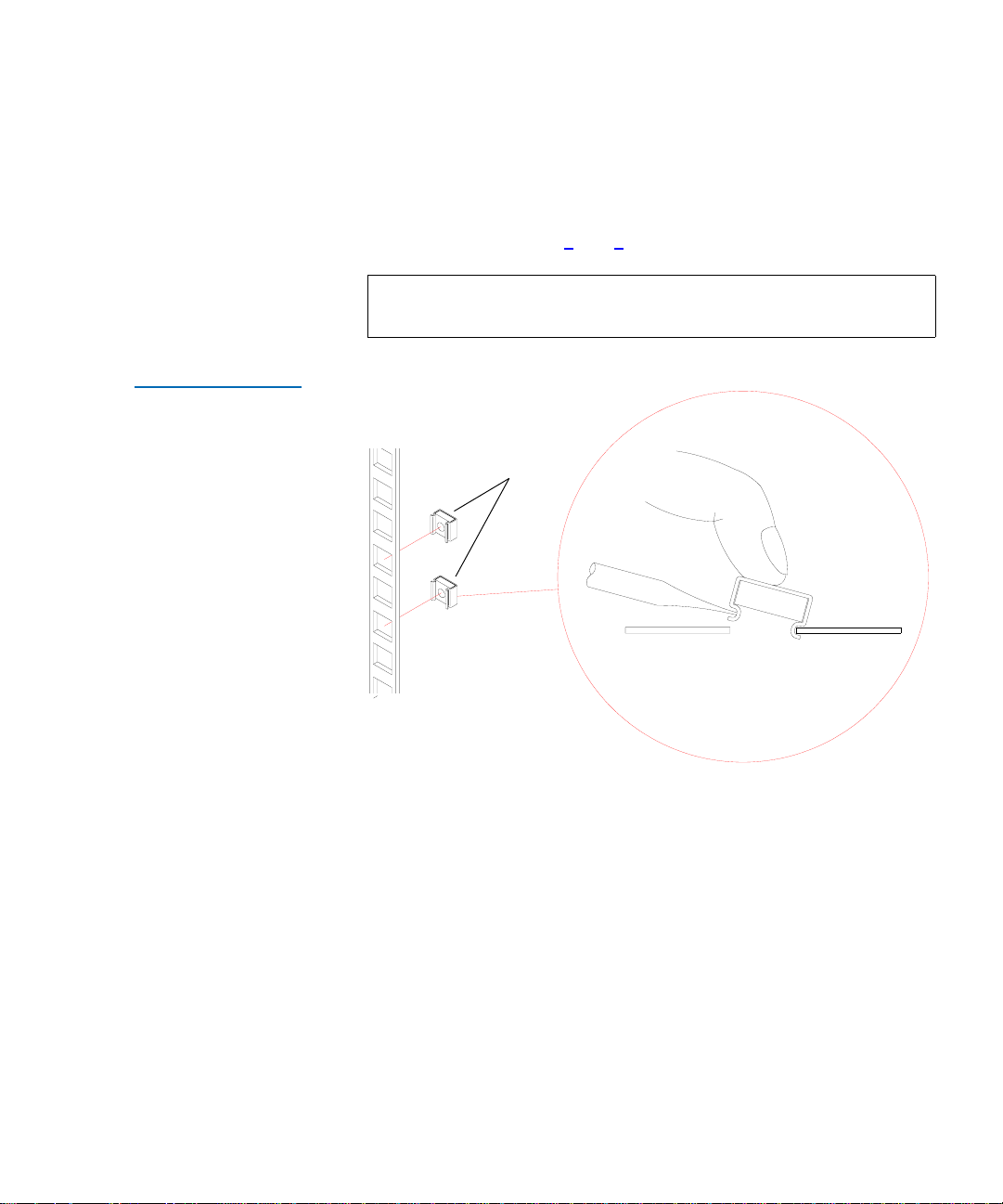
Figure 1 Inserting
Caged Nuts into the
Rack Rails
Chapter 1 Installing the StackLink
Preparing for the StackLink Installation
3 Use a pencil to mark the correct position of the mounting tray
assemblies on the rack rails.
4 If the holes in the rack rails are square (untapped), insert caged nuts
(PN YS42008) into the holes where the mounting tray assemblies will
be installed (see figures 1
and 2).
Note: Install the caged nuts on the back of the rack rails, facing
the interior of the rack.
Caged nuts
Flat blade
screwdriver
ATL StackLink™ Installation Instructions 5
Page 26
Chapter 1 Installing the StackLink
Preparing for the StackLink Installation
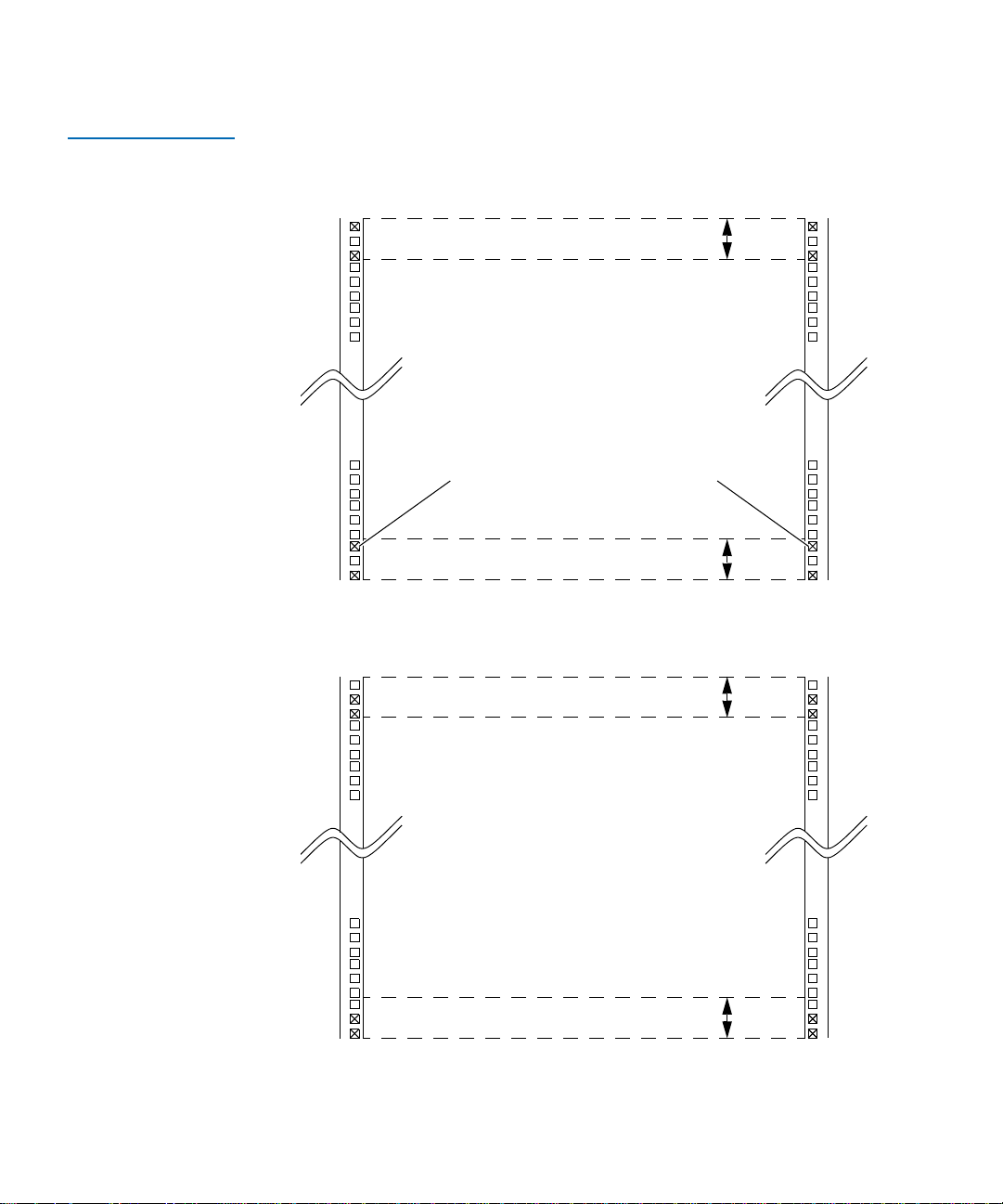
Figure 2 Caged Nut
Locations
Install caged nuts
in locations marked
by an “X”
If you are installing 3 ATL M2500 library modules
in the rack, do not put caged nuts in these locations
FRONT OF RACK
Top mounting tray position
Bottom mounting tray position
BACK OF RACK
1U
1U
Top mounting tray position
Bottom mounting tray position
6 ATL StackLink™ Installation Instructions
1U
1U
Page 27
Chapter 1 Installing the StackLink
Installing the Top Mounting Tray Assembly
Installing the Top Mounting Tray Assembly 1
To install the top mounting tray assembly in the rack:
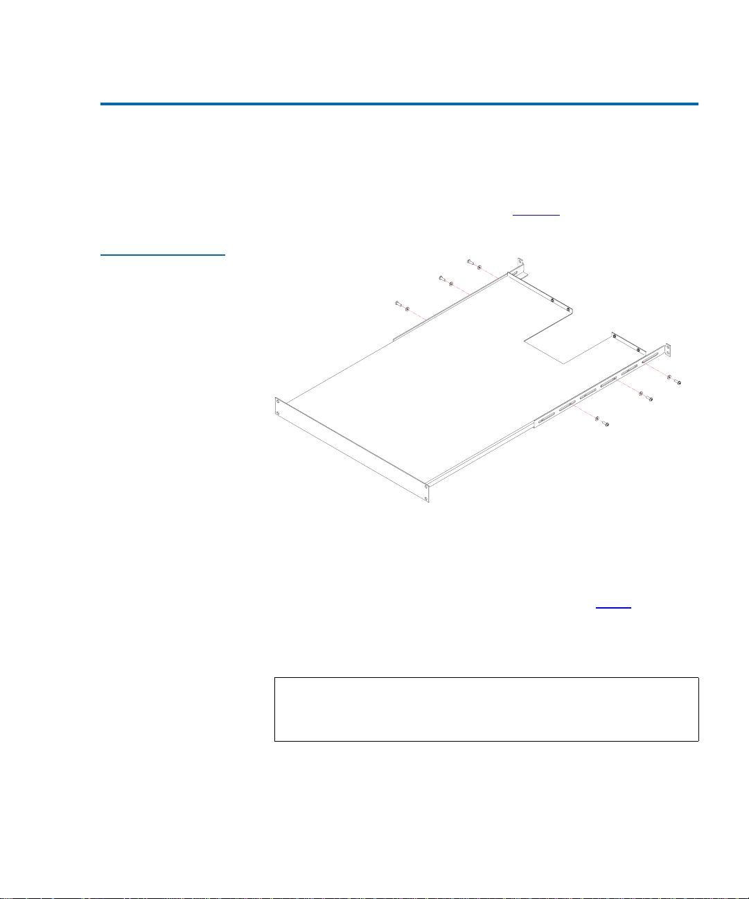
1 Remove the six screws and washers securing the rear support arms to
the sides of the top mounting tray (see figure 3
Figure 3 Adjusting the
Depth of the Top
Mounting Tray
Assembly
).
2 Adjust the position of the rear support arms on the top mounting tray
until the distance between the front and rear flanges is approximately
the same as the distance between the front and rear mounting strips
in the rack.
3 Replace the six screws and washers you removed in step 1
finger-tighten them. Position the front and rear screws as far apart as
the slots allow. Position the third screw approximately in the middle
slot.
Note: Do not over-tighten the screws. You need to be able to
extend or retract the rear support arms slightly as you
install the top mounting tray assembly.
ATL StackLink™ Installation Instructions 7
and
Page 28
Chapter 1 Installing the StackLink
Installing the Top Mounting Tray Assembly
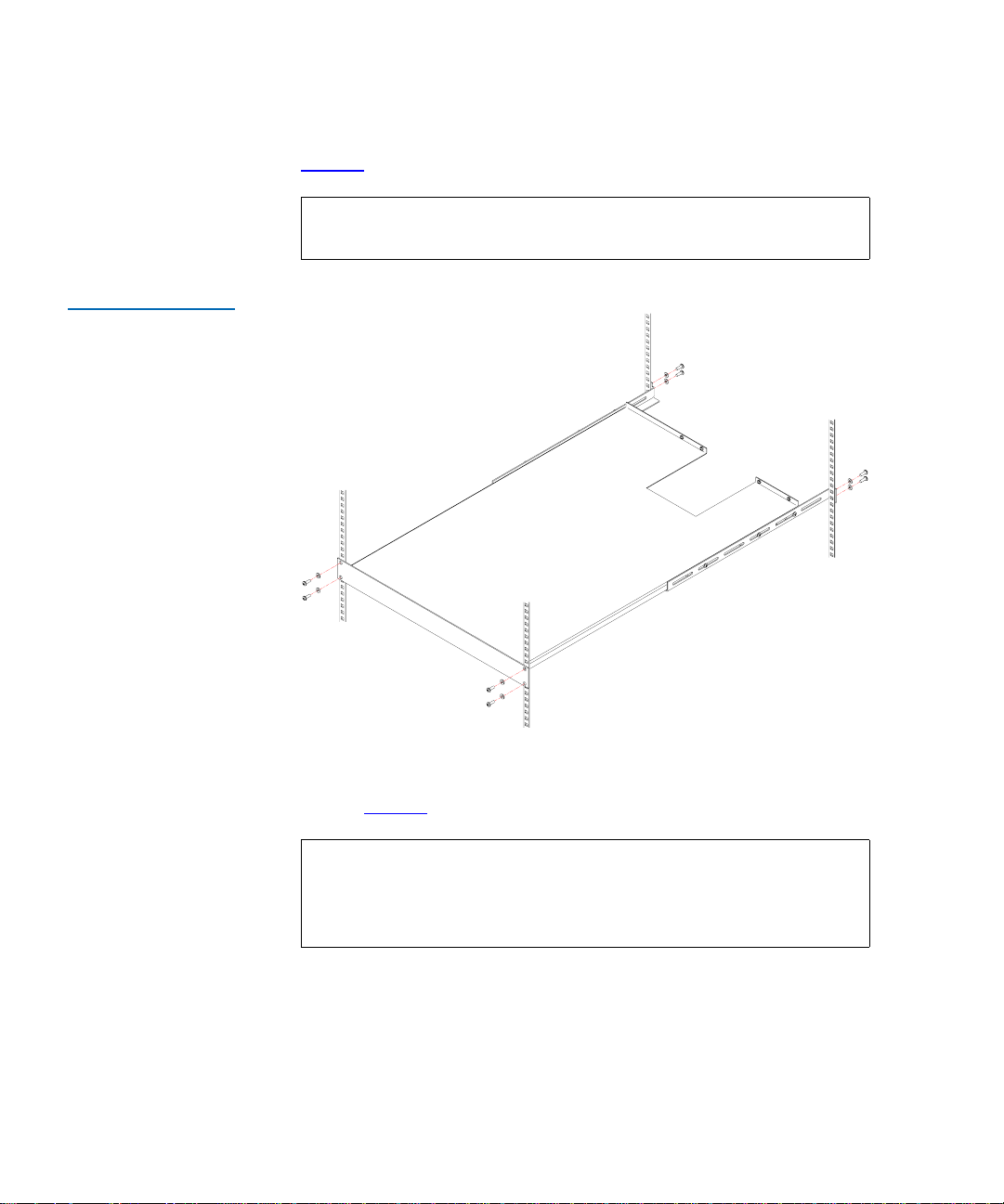
4 Position the top mounting tray assembly in the rack, referring to
figure 4
for the correct orientation.
Note: Position the front and rear flanges of the top mounting
Figure 4 Securing the
Top Mounting Tray
Assembly to the Rack
tray assembly outside of the rack rails.
REAR
FRONT
5 Secure the top mounting tray assembly to the rack, using eight screws
(PN YS42011) and washers (PN YS40404) provided in the StackLink
kit (see figure 4
).
Note: If the rack has widely spaced mounting holes, it may not
be possible to use all four screws to secure the rear flanges.
If this is the case, one screw per side at the rear is
acceptable.
6 Fully tighten the six screws and washers securing the rear support
arms to the sides of the top mounting tray.
8 ATL StackLink™ Installation Instructions
Page 29
Chapter 1 Installing the StackLink
Installing the Bottom Mounting Tray Assembly
Installing the Bottom Mounting Tray Assembly 1
To install the bottom mounting tray assembly in the rack:
1 If three ATL M2500 library modules will be installed in the rack,
remove the 1U panel from the front of the bottom mounting tray
assembly and replace it with the .5U panel provided in the StackLink
kit:
Caution: Do not remove this panel if fewer than three
ATL M2500 library modules will be installed in the
rack.
a Remove the five nuts securing the 1U panel to the front of the
bottom mounting tray assembly.
b Position the .5U panel (PN 215941) at the front of the bottom
mounting tray assembly and secure it using the five nuts you
removed in the previous step.
2 Remove the six screws and washers securing the rear support arms to
the sides of the bottom mounting tray (see figure 5
).
Figure 5 Adjusting the
Depth of the Bottom
Mounting Tray
Assembly
ATL StackLink™ Installation Instructions 9
Page 30
Chapter 1 Installing the StackLink
Installing the Bottom Mounting Tray Assembly
3 Adjust the position of the rear support arms on the bottom mounting
tray until the distance between the front and rear flanges is
approximately the same as the distance between the front and rear
mounting strips in the rack.
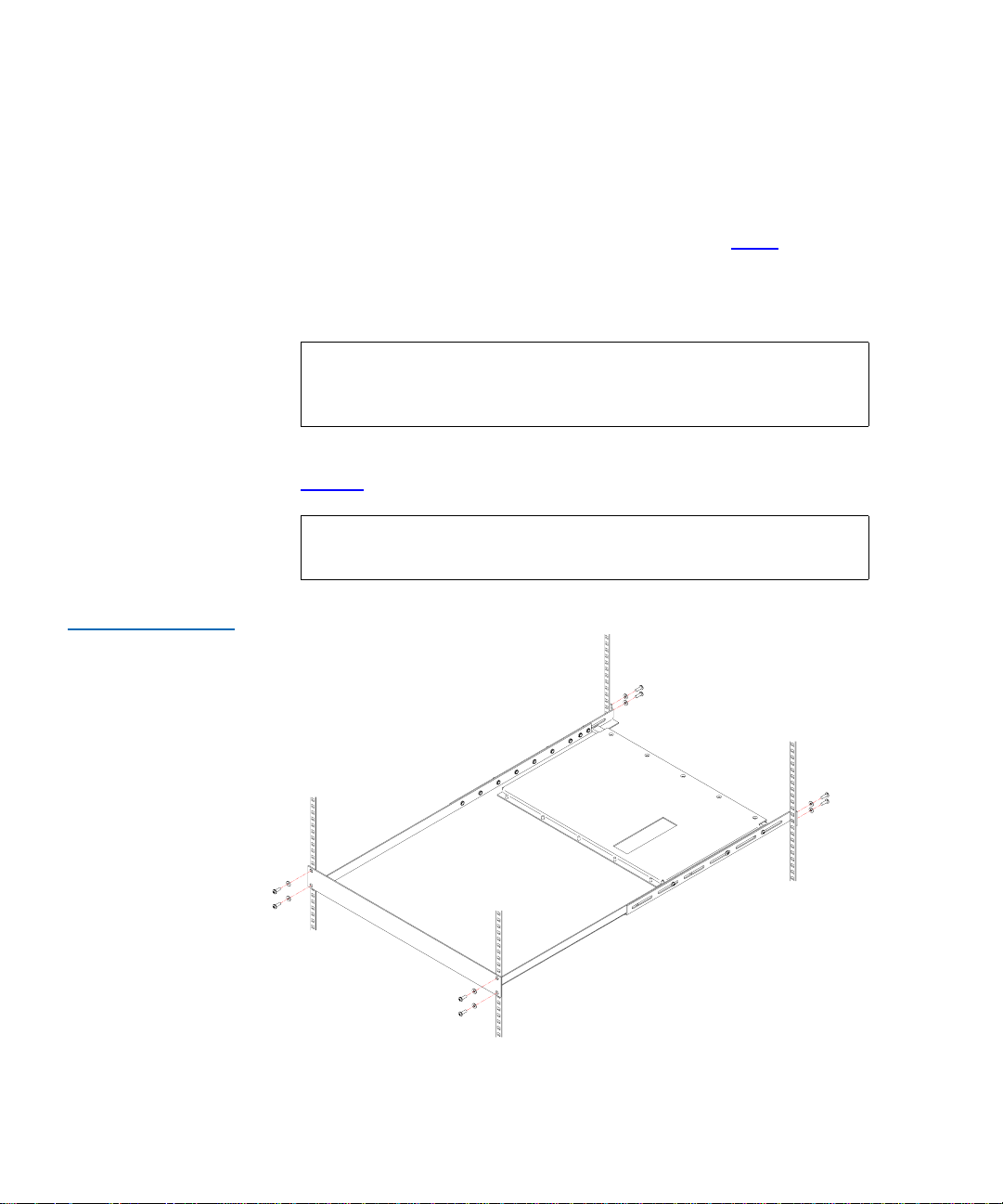
Figure 6 Securing the
Bottom Mounting Tray
Assembly to the Rack
4 Replace the six screws and washers you removed in step 2
and
finger-tighten them. Position the front and rear screws as far apart as
the slots allow. Position the third screw approximately in the middle
slot.
Note: Do not over-tighten the screws. You need to be able to
extend or retract the rear support arms slightly as you
install the bottom mounting tray assembly.
5 Position the bottom mounting tray assembly in the rack, referring to
figure 6
for the correct orientation.
Note: Position the front and rear flanges of the bottom mounting
tray assembly outside of the rack rails.
REAR
FRONT
10 ATL StackLink™ Installation Instructions
Page 31

Chapter 1 Installing the StackLink
Installing the Carriage/Counterweight Assembly
6 Secure the bottom mounting tray assembly to the rack, using the
screws (PN YS42011) and washers (PN YS40404) provided in the
StackLink kit (see figure 6
Note: If the rack has widely spaced mounting holes, it may not
be possible to use all four screws to secure the rear flanges.
If this is the case, one screw per side at the rear is
acceptable.
7 Fully tighten the six screws and washers securing the rear support
arms to the sides of the bottom mounting tray.
).
Installing the Carriage/Counterweight Assembly 1
Now that the top and bottom mounting trays are installed, install the
carriage/counterweight assembly on the vertical shuttle assembly (see
figure 7
):
1 Slide the counterweight onto the bottom of the vertical shuttle
assembly, engaging the guide wheels of the counterweight with the
vertical rails.
ATL StackLink™ Installation Instructions 11
Page 32

Chapter 1 Installing the StackLink
Installing the Carriage/Counterweight Assembly
Figure 7 Installing the
Carriage/
Counterweight
Assembly
Belt
Carriage
Shuttle extrusion
Counterweight
12 ATL StackLink™ Installation Instructions
Page 33

Chapter 1 Installing the StackLink
Installing the Carriage/Counterweight Assembly
2 Route the belt connecting the counterweight and carriage up and
over the top of the vertical shuttle assembly, making sure not to twist
the belt.
3 Slide the carriage onto the top of the vertical shuttle assembly,
engaging the guide wheels of the carriage with the vertical rails.
4 Secure the umbilical cable to the underside of the carriage (see
figure 8
):
a Locate the pin on the underside of the carriage.
b Slide the umbilical cable underneath the open end of the pin.
c Rotate the pin until the umbilical cable is held snugly.
d Tighten the screw to secure the pin.
Caution: Do not over-tighten the screw.
5 Snap the end of the umbilical chain onto the bottom of the carriage
(see figure 8
).
6 Connect the end of the umbilical cable to the socket on the carriage
connection board (see figure 8
).
ATL StackLink™ Installation Instructions 13
Page 34

Chapter 1 Installing the StackLink
Installing the Carriage/Counterweight Assembly
Figure 8 Connecting
the Umbilical Cable to
the Bottom of the
Carriage
Screw
Carriage
Umbilical cable
Pin
14 ATL StackLink™ Installation Instructions
Umbilical chain
Umbilical cable
Page 35

Chapter 1 Installing the StackLink
Installing the Motor Assembly
Installing the Motor Assembly 1
To secure the motor assembly to the vertical shuttle assembly:
1 Insert the bottom of the motor assembly into the top of the vertical
shuttle assembly, aligning the two holes in the vertical shuttle
assembly with those on the motor assembly (see figure 9
Figure 9 Inserting the
Motor Assembly into
the Vertical Shuttle
Assembly
).
hese two holes align with
les in the motor assembly
ATL StackLink™ Installation Instructions 15
Page 36

Chapter 1 Installing the StackLink
k
Installing the Motor Assembly
2 Secure the motor assembly to the vertical shuttle assembly, using two
countersink screws (PN YS42038) and one pan head screw
(PN YS41964) (see figure 10
).
Figure 10 Securing
the Motor Assembly to
the Vertical Shuttle
Assembly
Figure 11 Routing the
Belt
Countersin
screws
(YS42038)
Motor assembly
Pan head
screw
YS41964)
Vertical
rail assembly
3 Route the belt connecting the counterweight and the carriage over the
guide roller and past the motor/pulley belt retainer on the motor
assembly (see figure 11
).
16 ATL StackLink™ Installation Instructions
Page 37

Figure 12 Connecting
the Ribbon Cable
Chapter 1 Installing the StackLink
Attaching the Shuttle Assembly to the Mounting Tray Assemblies
4 Connect the ribbon cable from the vertical shuttle assembly to the
socket on the control board at the rear of the motor assembly as
shown in figure 12
a Route the ribbon cable behind the motor plate.
b Insert the ribbon cable connector through the rectangular hole at
the top of the motor plate.
c Connect the ribbon cable connector to the socket on the control
board.
:
Rectangular hole
Motor plate
Ribbon cable
Attaching the Shuttle Assembly to the Mounting Tray
Assemblies
To attach the shuttle assembly to the top and bottom mounting tray
assemblies:
1 At the rear of the rack, lift the shuttle assembly and position it so the
carriage faces forward into the rack.
2 Rest the lower end of the shuttle assembly on top of the bottom
mounting tray assembly.
ATL StackLink™ Installation Instructions 17
1
Page 38

Chapter 1 Installing the StackLink
Attaching the Shuttle Assembly to the Mounting Tray Assemblies
3 Ensure that the motor at the top of the shuttle assembly is aligned
with the cutout in the top mounting tray assembly.
4 Slide the shuttle assembly fully into the rack.
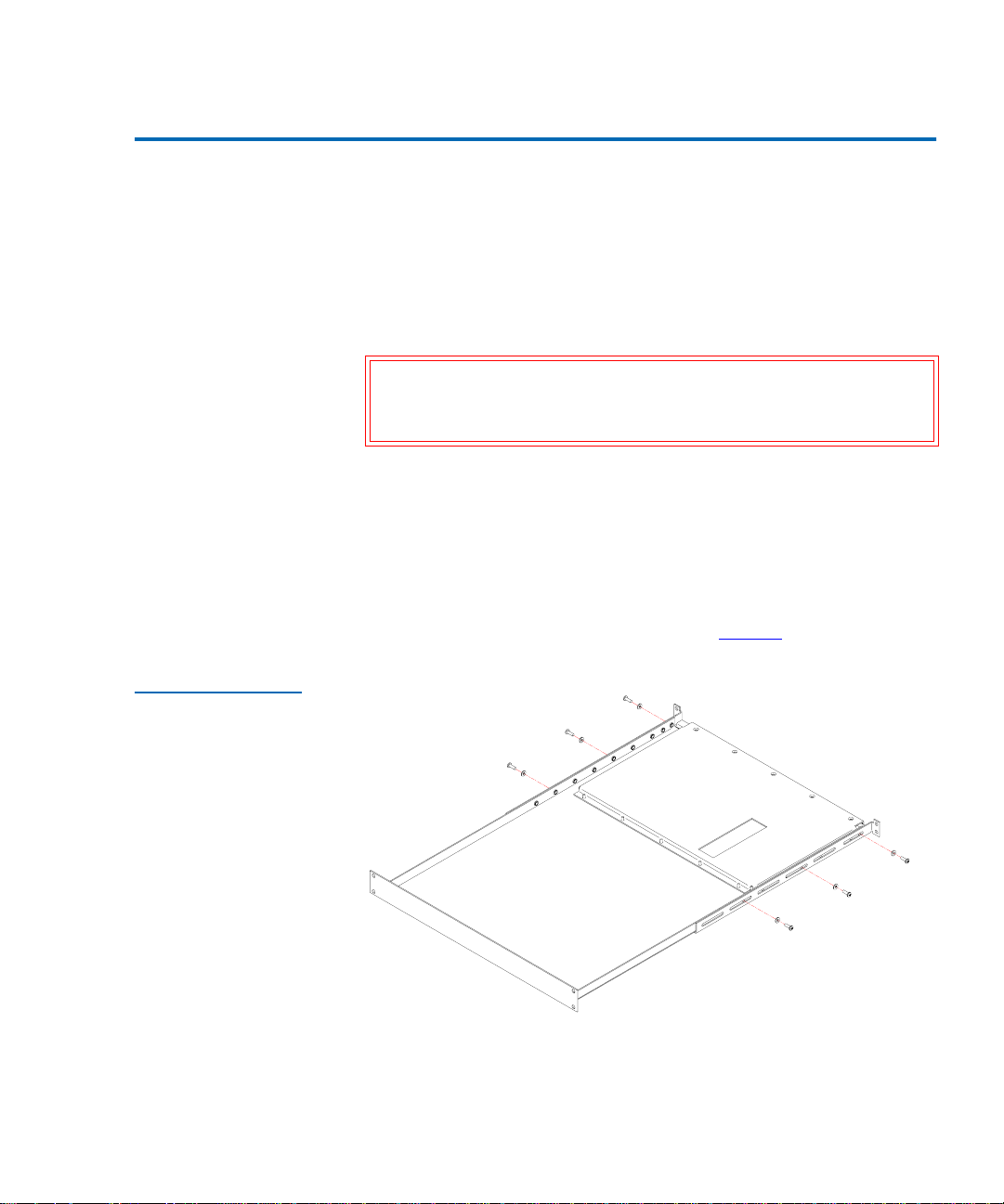
5 Secure the shuttle assembly to the upper and lower mounting trays
using six screws (PN YS41952) and washers (PN YS40402) provided
in the StackLink kit (see figure 13
Note: Tighten these screws to finger-tightness only. You will
finish securing the StackLink after you have installed
libraries in the rack.
).
Figure 13 Installing
the Shuttle Assembly
(SHOWN OUTSIDE OF RACK)
FRONT
REAR
Now that the StackLink is installed, proceed to the next chapter to
install the rack mount shelves.
18 ATL StackLink™ Installation Instructions
Page 39

Chapter 2
2Installing the
Rack Mount Shelves
This chapter explains how to install the ATL M1500 and ATL M2500 rack
mount shelves.
Caution: When installing the rack mount shelves, keep in mind that
the libraries must be installed contiguously, from the top
of the rack downward, with no space between the
libraries. Due to the way the library firmware calculates
the library size and assigns SCSI element addresses,
installing the libraries non-contiguously can cause
problems with the backup software.
For example, the top library in a multiple library stack
must be installed directly beneath the StackLink upper
mounting tray. Each subsequent library must be installed
directly beneath the previous library, with no space in
between.
For information about how the library firmware calculates
library size and assigns SCSI element addresses, see
appendix A, Library Size,
SCSI Element Addressing, on page 95.
ATL StackLink™ Installation Instructions 19
on page 89 and appendix B,
Page 40

Chapter 2 Installing the Rack Mount Shelves
Determining the Position of the Shelves in the Rack
Determining the Position of the Shelves in the Rack 2
Before starting to install the rack mount shelves:
1 Determine the proper position of the shelves in the rack (see
figure 14
• Racks are measured in rack mount units. Each unit is called a
• An ATL M1500 library uses 4U of vertical space. The ATL M1500
• An ATL M2500 library uses 13.5U of vertical space. The
):
“U,” and is equal to 1.75 inches (44.45 millimeters). When you
look at the rack rails, you will notice that the holes are divided
into groups of three, with each group separated by a slightly
smaller space. Each group of three equally spaced holes is one U
(see figure 14
rack mount shelves must be installed in a full U position (the
bottom of the rack mount shelf must be aligned with the bottom
of a U).
ATL M2500 rack mount shelves can be installed in either a full U
or a half U position (the bottom of the rack mount shelf may be
aligned with either the bottom or the middle of a U).
).
2 Mark the desired shelf position on the rack rails.
20 ATL StackLink™ Installation Instructions
Page 41

Figure 14 Example of
Full and Half U
Mounting Positions
In the half U position, the bottom of
the mounting bracket aligns with the
center of the middle hole in the
corresponding U. This position can be
used for ATL M2500 rack mount
shelves only.
Chapter 2 Installing the Rack Mount Shelves
Determining the Position of the Shelves in the Rack
3 equally
spaced holes
equals 1 U
1 U
In the full U position, the bottom of the
mounting bracket aligns with the
bottom of the corresponding U. This
position can be used for either
ATLM1500 or ATL M2500 rack
mount shelves
ATL StackLink™ Installation Instructions 21
Page 42

Chapter 2 Installing the Rack Mount Shelves
Installing the Shelves
Installing the Shelves 2
The rack mount shelves are intended to accommodate a variety of the
most commonly available rack rail configurations. The installation
instructions vary depending on the rail configuration you have. To install
the rack mount shelves for an:
• ATL M1500 library, refer to the following section, Installing the
ATL M1500 Rack Mount Shelves
• ATL M2500 library, refer to Installing the ATL M2500 Rack Mount
Shelves on page 30
Caution: Read the shelf installation instructions thoroughly. Failure
to use the designated inserts, screws, and clamps could
result in the library falling from the rack.
Installing the ATL M1500 Rack Mount Shelves
This section explains how to install the ATL M1500 rack mount shelves.
2
Checking the Contents of the Rack Mount Kit
Table 2 lists the contents of the ATL M1500 Universal Rack Mount Kit. If
any items are missing, contact Quantum (see Customer Support
page xix).
2
on
22 ATL StackLink™ Installation Instructions
Page 43

Chapter 2 Installing the Rack Mount Shelves
Installing the Shelves
Table 2 Contents,
ATLM1500 Universal
Rack Mount Kit
Part No. Description Qty.
213467 Shelf clamp 4
213468 Insert (9 sq) 8
213469 Insert (7 sq) 8
213471 Insert (M6) 8
213472 Insert (M5 or 12-24UNC) 8
213473 Insert (10-32UNF) 8
213474 Insert (1/4" dia) 8
213476 Universal shelf, right 1
213477 Universal shelf, left 1
213478 Shelf extender #1 1
213479 Shelf extender #2 1
YS40403 Plain washer M5 4
YS40403 Plain washer M5 2
YS41720 Button head socket screw 10-24 UNC x 0.5 ins 2
YS41998 Nut, M5 full 4
YS42008 M6 cage nut 2
YS42011 Button head socket screw M6 x 12 2
YS42038 Countersink hex socket screw M4 X 10 LG 4
YS42042 Button head socket screw M5 x 12 2
YS42043 Button head socket screw 10-32 UNC x 0.5 ins 2
YS42044 M5 spire nut 2
ATL StackLink™ Installation Instructions 23
Page 44

Chapter 2 Installing the Rack Mount Shelves
Installing the Shelves
Verif ying That You Have the Required Tools 2
The following tools are required to install the rack mount kit:
• 8 mm open end wrench
• 2.5 mm socket driver (preferably ball headed)
• Flat blade screwdriver
• Tape measure
Assembling the Rack Mount Shelves
Each rack mount shelf consist of a rack mount shelf and an extender. To
assemble the rack mount shelves:
1 Measure the distance between the inside surfaces of the front and
rear rack rails, then find the corresponding rack depth in table 3
.
2 Assemble the left shelf:
a Refer to the
Left Shelf/Shelf Extender column of table 3 to
determine which shelf extender to combine with the left
universal shelf.
b Insert the posts on the left universal shelf through the shelf
extender slots identified in the
Left Shelf/Slots column of table 3.
The slots in the shelf extenders are identified as shown in
figure 16
.
c Use the M5 nuts (PN YS41998) and M5 washers (PN YS40403)
provided in the rack mount kit to fasten the left shelf and shelf
extender together (see figure 16
).
Note: Tighten the nuts to finger-tightness only. You need to be
able to retract and extend the assembled shelves slightly.
2
3 Assemble the right shelf in the same manner, referring to the
Shelf
column of table 3.
24 ATL StackLink™ Installation Instructions
Right
Page 45

Chapter 2 Installing the Rack Mount Shelves
Installing the Shelves
Table 3 Shelf
Assembly Matrix
Figure 15 Identifying
the Shelf Extender
Slots
Rack Depth
(between flanges)
24.50 in. - 26.75 in.
(620 mm - 680 mm)
26.75 in. - 29.125 in.
(680 mm - 740 mm)
29.125 in. - 31.50 in.
(740 mm - 800 mm)
31.50 in. - 33.875 in
(800 mm - 860 mm)
33.875 in. - 36.25 in.
(860 mm - 920 mm)
Left Shelf Right Shelf
Shelf
Extender Slots
Shelf
Extender Slots
#2 A & B #1 A & B
#1 B & C #2 A & B
#2 B & C #1 B & C
#1 C & D #2 B & C
#2 C & D #1 C & D
A
B
C
D
ATL StackLink™ Installation Instructions 25
Page 46

Chapter 2 Installing the Rack Mount Shelves
Installing the Shelves
Figure 16 Attaching
the Shelves to the
Extenders
Extender
Shelf
Installing the Rack Mount Shelves 2
To install the rack mount shelves:
1 From the six sizes of inserts provided in the rack mount kit, select the
insert type that best fits the holes in your rack rails. The insert part
numbers are:
• 213468 (for rails with 9 mm square holes)
• 213469 (for rails with 7 mm diameter unthreaded holes)
• 213471 (for rails with M6 threaded holes)
• 213472 (for rails with 12-24 UNC or M5 threaded holes)
• 213473 (for rails with 10-32 UNF threaded holes)
• 213474 (for rails with 1/4 in. diameter unthreaded holes)
The heads of the inserts (not the threads) should fit into the rack rail
holes smoothly and with very little play.
2 Once you have selected the inserts you will use, set the remaining
inserts aside. You do not need them for this installation.
26 ATL StackLink™ Installation Instructions
Page 47

Figure 17 Installing
the Inserts in the
Shelves
Chapter 2 Installing the Rack Mount Shelves
Installing the Shelves
3 Screw the inserts into the two outer holes on each end of the
assembled shelves (see figure 17
).
Note: Some of the inserts have either no head or a head that has
a smaller diameter than the thread; these need to be left
protruding by about 1/8 in. (3 mm). The inserts with
heads should be tightened fully.
Inserts
ATL StackLink™ Installation Instructions 27
Page 48

Chapter 2 Installing the Rack Mount Shelves
Installing the Shelves
4 Install the left shelf (see figure 18):
a With the shelf slightly retracted, position the shelf in the rack at
the desired mounting height.
b Expand the shelf so that the inserts on each end of the shelf
protrude into the holes in the rack rails and hold the shelf in
place.
5 Repeat the above steps to install the right shelf.
Figure 18 Installing
the Shelf in the Rack
Inserts protrude
through the
holes in the rails
6 Secure the shelves (see figure 19):
a Position a shelf clamp (PN 213467) on the front left rack rail.
The bottom of the shelf clamp should be flush with the bottom of
the shelf.
b Secure the shelf clamp to the rack rail using an M4 countersink
screw (PN YS42038).
28 ATL StackLink™ Installation Instructions
Page 49

Figure 19 Securing
the Shelf Clamp to the
Rail
Chapter 2 Installing the Rack Mount Shelves
Installing the Shelves
c Repeat these steps to install shelf clamps at the front and back of
each shelf.
d Tighten the nuts securing the shelves to the shelf extenders.
Shelf clamp
Once you have installed all the rack mount shelves, proceed to the
next chapter, Installing the Libraries
.
Note: The universal rack mount kit contains screws and nuts for
many different types of rack. You will have many of these
screws and nuts left over after installing the rack mount
shelves and library.
ATL StackLink™ Installation Instructions 29
Page 50

Chapter 2 Installing the Rack Mount Shelves
Installing the Shelves
Installing the ATL M2500 Rack Mount Shelves
Table 4 Contents,
ATLM2500 Universal
Rack Mount Kit
This section explains how to install the ATL M2500 rack mount shelves.
2
Checking the Contents of the Rack Mount Kit
Table 4 lists the contents of the ATL M2500 Universal Rack Mount Kit. If
any items are missing, contact Quantum (see Customer Support
page xix).
Part No. Description Qty.
213468 Insert (9 sq) 12
213469 Insert (7 sq) 12
213471 Insert (M6) 12
213473 Insert (10-32 UNF, 12-24 UNC, or M5) 12
213474 Insert (1/4 inch diameter) 12
215812 Front shelf clamp 4
217405 Clamp strip 2
2
on
215197/02 Universal shelf, right 1
215198/02 Universal shelf, left 1
215199/01 Shelf extender, long #1 1
215200/01 Shelf extender, long #2 1
215201/01 Rear shelf clamp 2
YS40403 Plain washer M5 8
YS41998 Nut, M5 full 8
YS42064 Countersink hex socket screw M4 x 12 LG 12
30 ATL StackLink™ Installation Instructions
Page 51

Chapter 2 Installing the Rack Mount Shelves
Installing the Shelves
Verifying That You Have the Required Tools 2
The following tools are required to install the rack mount kit:
• 8 mm open end wrench
• 2.5 mm socket driver (preferably ball headed)
• Flat blade screwdriver
• Tape measure
Assembling the Rack Mount Shelves
To assemble the rack mount shelves:
1 Measure the distance between the inside surfaces of the front and
rear rack rails, then find the corresponding rack depth in table 5
2 Assemble the left shelf:
a Refer to the
Left Shelf/Shelf Extender column of table 5 to
determine which shelf extender to combine with the left
universal shelf.
b Insert the posts on the left universal shelf through the shelf
extender slots identified in the
Left Shelf/Slots column of table 5.
The slots in the shelf extenders are identified as shown in
figure 20
.
c Use the M5 nuts (PN 41998) and M5 washers (PN YS40403)
provided in the rack mount kit to fasten the left shelf and shelf
extender together (see figure 21
).
Note: Tighten the nuts to finger-tightness only; you need to be
able to retract and extend the assembled shelves slightly.
3 Assemble the right shelf in the same manner, referring to the
Shelf
column of table 5.
Right
2
.
ATL StackLink™ Installation Instructions 31
Page 52

Chapter 2 Installing the Rack Mount Shelves
Installing the Shelves
Table 5 Shelf
Assembly Matrix
Figure 20 Identifying
the Shelf Extender
Slots
Rack Depth
(between flanges)
24.25 in. to 26.75 in.
(617 mm to 680 mm)
26.75 in. to 29.125 in.
(680 mm to 740 mm)
29.125 in. to 31.5 in.
(740 mm to 800 mm)
31.5 in. to 33.875 in.
(800 mm to 860 mm)
33.875 in. to 36.25 in.
(860 mm to 920 mm)
C
D
C
D
Left Shelf Right Shelf
Shelf
Extender Slots
Shelf
Extender Slots
Long #2 A & B Long #1 A & B
Long #1 B & C Long #2 A & B
Long #2 B & C Long #1 B & C
Long #1 C & D Long #2 B & C
Long #2 C & D Long #1 C & D
A
B
A
B
B
C
C
D
D
B
A
A
32 ATL StackLink™ Installation Instructions
Page 53

Chapter 2 Installing the Rack Mount Shelves
Installing the Shelves
Figure 21 Attaching
the Shelves to the
Extenders
Shelf
Extender
Installing the Shelves in a Half U Positi on 2
To install the rack mount shelves in a half U position:
Note: The top and bottom libraries in a 3-high ATL M2500 stack are
mounted in a half U position.
1 From the six sizes of inserts provided in the rack mount kit, select the
insert type that best fits the holes in your rack rails. The insert part
numbers are:
• 213468 (for rails with 9 mm square holes)
• 213469 (for rails with 7 mm diameter unthreaded holes)
• 213471 (for rails with M6 threaded holes)
• 213473 (for rails with 10-32 UNF, 12-24 UNC, or M5 threaded
holes)
• 213474 (for rails with 1/4 inch diameter unthreaded holes)
The heads of the inserts (not the threads) should fit into the holes in
the rack rails smoothly and with very little play.
2 Once you have selected the inserts you will use, set the remaining
inserts aside. You do not need them for this installation.
ATL StackLink™ Installation Instructions 33
Page 54

Chapter 2 Installing the Rack Mount Shelves
Installing the Shelves
3 Screw three inserts into the front flange of each rack mount shelf in
positions 2, 6, and 10 (counting from the bottom up, with 1 being the
lowest hole) (see figure 22
Note: Some of the inserts have either no head or a head that has
a smaller diameter than the thread; these need to be left
protruding by about 1/8 in. (3 mm). The inserts with
heads should be tightened fully.
Figure 22 Installing
Inserts at the Front of
the Shelves
).
10
6
2
10
6
2
4 Screw three inserts into the rear flange of each rack mount shelf in the
positions shown in figure 23
. If the shelves are oriented so the group
of six holes is at the bottom and the group of four holes is at the top,
the inserts go into holes 2, 6, and 9 (counting from the bottom up,
with 1 being the lowest hole).
Note: Some of the inserts have either no head or a head that has
a smaller diameter than the thread; these need to be left
protruding by about 1/8 in. (3 mm). The inserts with
heads should be tightened fully.
34 ATL StackLink™ Installation Instructions
Page 55

Figure 23 Installing
Inserts at the Rear of
the Shelves
Chapter 2 Installing the Rack Mount Shelves
Installing the Shelves
Figure 24 Installing
the Shelves
Group of 6 holes
Group of 4 holes
Group of 4 holes
Group of 6 holes
2
6
9
9
6
2
5 Install the shelves (see figure 24):
a With the shelf slightly retracted, position the shelf in the rack at
the desired mounting height.
b Expand the shelf so that the inserts on each end of the shelf
protrude into the holes in the rack rails and hold the shelf in
place.
c Repeat these steps to install the remaining shelf.
Inserts protrude
through the
holes in the rails
ATL StackLink™ Installation Instructions 35
Page 56

Chapter 2 Installing the Rack Mount Shelves
Installing the Shelves
6 Install the front shelf clamps (see figure 25):
a Position a front shelf clamp (PN 215812) on the front left rack rail.
The square holes in the front shelf clamp should be aligned with
the upper two inserts in the front shelf flange.
b Secure the front shelf clamp to the rack rail using two M4
countersink screws (PN YS42064).
c Repeat these steps to install a front shelf clamp on the front right
rack rail.
Figure 25 Installing
the Front Shelf
Clamps
7 Install the rear shelf clamps (see figure 26):
a Position a rear shelf clamp (PN 215201/01) on the rear left rack
rail, aligning the square hole with the middle insert in the shelf
flange.
36 ATL StackLink™ Installation Instructions
Page 57

Figure 26 Installing
the Rear Shelf Clamps
Chapter 2 Installing the Rack Mount Shelves
Installing the Shelves
b Verify that two of the round holes line up with holes in the rack
mount shelf. If two of the holes do not line up, rotate the clamp
180 degrees.
c Secure the rear shelf clamp to the shelf using two M4 countersink
screws (PN YS42064).
d Repeat these steps to install a rear shelf clamp on the rear right
rack rail.
Note: The left and right rear shelf clamps will be oriented
differently from one another.
ATL StackLink™ Installation Instructions 37
Page 58

Chapter 2 Installing the Rack Mount Shelves
Installing the Shelves
8 Install the clamp strips (see figure 27):
a Position a front shelf clamp (PN 215812) at the front of the front
left rack rail, with the bottom of the clamp approximately 15.5
inches (394 millimeters) above the bottom of the rack mount
shelf.
Caution: The top of the front shelf clamp must be no more than
b Position a clamp strip (PN 217405) behind the front left rack rail,
aligning it with the front shelf clamp.
c Insert a screw (PN YS42064) through the upper hole in the front
shelf clamp, through the rack rail, and into the upper hole in the
clamp strip.
d Insert a screw (PN YS42064) through the bottom hole in the front
shelf clamp, through the rack rail, and into the bottom hole in the
clamp strip.
22.75 in. (580 mm) above the bottom of the rack mount
shelf.
e Repeat steps 8
a through 8d to install the front shelf clamp and
clamp strip on the right rack rail.
38 ATL StackLink™ Installation Instructions
Page 59

Chapter 2 Installing the Rack Mount Shelves
Installing the Shelves
Figure 27 Installing
the Clamp Strips
Clamp strip
Front shelf clamp
9 Tighten the nuts securing the shelves to the shelf extenders.
Once you have installed all the rack mount shelves, proceed to the
next chapter, Installing the Libraries
on page 47.
Note: The universal rack mount kit contains screws and nuts for
many different types of rack. You will have many of these
screws and nuts left over after installing the rack mount
shelves and library.
ATL StackLink™ Installation Instructions 39
Page 60

Chapter 2 Installing the Rack Mount Shelves
Installing the Shelves
Installing the Shelves in a Full U Position 2
To install the rack mount shelves in a full U position:
Note: The middle library in a 3-high ATL M2500 stack is mounted in
a full U position.
1 From the six sizes of inserts provided in the rack mount kit, select the
appropriate inserts for your rack. The insert part numbers are:
• 213468 (for rails with 9 mm square holes)
• 213469 (for rails with 7 mm diameter unthreaded holes)
• 213471 (for rails with M6 threaded holes)
• 213473 (for rails with 10-32 UNF, 12-24 UNC, or M5 threaded
holes)
• 213474 (for rails with 1/4 inch diameter unthreaded holes)
The heads of the inserts (not the threads) should fit into the holes in
the rack rails smoothly and with very little play.
2 Screw three inserts into the front flange of each rack mount shelf in
positions 1, 4, and 8 (counting from the bottom up, with 1 being the
lowest hole) (see figure 22
).
Note: Some of the inserts have either no head or a head that has
a smaller diameter than the thread; these need to be left
protruding by about 1/8 in. (3 mm). The inserts with
heads should be tightened fully.
40 ATL StackLink™ Installation Instructions
Page 61

Figure 28 Installing
Inserts at the Front of
the Shelves
Chapter 2 Installing the Rack Mount Shelves
Installing the Shelves
Figure 29 Installing
Inserts at the Rear of
the Shelves
8
4
1
8
4
1
3 Screw three inserts into the rear flange of each rack mount shelf in the
positions shown in figure 29
. If the shelves are oriented so the group
of six holes is at the bottom and the group of four holes is at the top,
the inserts go into holes 1, 5, and 10 (counting from the bottom up,
with 1 being the lowest hole).
Note: Some of the inserts have either no head or a head that has
a smaller diameter than the thread; these need to be left
protruding by about 1/8 in. (3 mm). The inserts with
heads should be tightened fully.
Group of 6 holes
Group of 4 holes
1
5
10
Group of 4 holes
10
Group of 6 holes
5
1
ATL StackLink™ Installation Instructions 41
Page 62

Chapter 2 Installing the Rack Mount Shelves
Installing the Shelves
4 Install the shelves (see figure 30):
a With the shelf slightly retracted, position the shelf in the rack at
the desired mounting height.
b Expand the shelf so that the inserts on each end of the shelf
protrude into the holes in the rack rails and hold the shelf in
place.
c Repeat these steps to install the remaining shelf.
Figure 30 Installing
the Shelves
Inserts protrude
through the
holes in the rails
5 Install the front shelf clamps (see figure 31):
a Position a front shelf clamp (PN 215812) on the front left rack rail.
The square holes in the front shelf clamp should be aligned with
the upper two inserts in the front shelf flange.
b Secure the front shelf clamp to the rack rail using two M4
countersink screws (PN YS42064).
c Repeat these steps to install a front shelf clamp on the front right
rack rail.
42 ATL StackLink™ Installation Instructions
Page 63

Figure 31 Installing
the Front Shelf
Clamps
Chapter 2 Installing the Rack Mount Shelves
Installing the Shelves
6 Install the rear shelf clamps (see figure 32):
a Position a rear shelf clamp (PN 215201/01) on the rear left rack
rail, aligning the square hole with the middle insert in the shelf
flange.
b Verify that two of the round holes line up with holes in the rack
mount shelf. If two of the holes do not line up, rotate the clamp
180 degrees.
c Secure the rear shelf clamp to the shelf using two M4 countersink
screws (PN YS42064).
d Repeat these steps to install a rear shelf clamp on the rear right
rack rail.
Note: The left and right rear shelf clamps will be oriented
differently from one another.
ATL StackLink™ Installation Instructions 43
Page 64

Chapter 2 Installing the Rack Mount Shelves
Installing the Shelves
Figure 32 Installing
the Rear Shelf Clamps
7 Install the clamp strips (see figure 33):
a Position a front shelf clamp (PN 215812) at the front of the front
left rack rail, with the bottom of the clamp approximately 15.5
inches (394 millimeters) above the bottom of the rack mount
shelf.
Caution: The top of the front shelf clamp must be no more than
22.75 in. (580 mm) above the bottom of the rack mount
shelf.
b Position a clamp strip (PN 217405) behind the front left rack rail,
aligning it with the shelf clamp.
c Insert a screw (PN YS42064) through the upper hole in the front
shelf clamp, through the rack rail, and into the upper hole in the
clamp strip.
d Insert a screw (PN YS42064) through the bottom hole in the front
shelf clamp, through the rack rail, and into the bottom hole in the
clamp strip.
44 ATL StackLink™ Installation Instructions
Page 65

Chapter 2 Installing the Rack Mount Shelves
Installing the Shelves
e Repeat steps 7a through 7d to install the front shelf clamp and
clamp strip on the right rack rail.
Figure 33 Installing
the Clamp Strips
Clamp strip
Front shelf clamp
8 Tighten the nuts securing the shelves to the shelf extenders.
Once you have installed all the rack mount shelves, proceed to the
next chapter, Installing the Libraries
.
Note: The universal rack mount kit contains screws and nuts for
many different types of rack. You will have many of these
screws and nuts left over after installing the rack mount
shelves and library.
ATL StackLink™ Installation Instructions 45
Page 66

Chapter 2 Installing the Rack Mount Shelves
Installing the Shelves
46 ATL StackLink™ Installation Instructions
Page 67

3Installing the Libraries
This chapter explains how to install the libraries, including:
• Installing the Libraries in the Rack
• Installing Tape Drives in the Libraries
• Installing the Safety Blanking Panels
• Preparing and Inserting Tape Cartridges
Chapter 3
ATL StackLink™ Installation Instructions 47
Page 68

Chapter 3 Installing the Libr a ri es
Installing the Libraries in the Rack
Installing the Libraries in the Rack 3
To install the libraries:
Warning: The ATL M1500 library weighs approximately 54 lbs (24.5
kg). The ATL M2500 library weighs approximately 152 lbs.
(69 kg). At least two people are required to lift and install
these libraries.
1 Unpack the library modules, referring to the ATL M1500 Library
Unpacking Instructions (PN 6421002) and the ATL M2500 Library
Unpacking Instructions (PN 6423000).
Caution: Make sure to remove the StackLink cover plate from
each library.
2 Verify that the rack mount shelves are level and securely fastened to
the rack.
3 With the help of another person, lift the library module onto the rack
mount shelves.
Caution: When sliding the library into the rack, be very careful
not to abrade or disconnect the ribbon cable that
connects the vertical shuttle assembly to the control
board on the motor assembly. See figure 12
location of this cable.
4 Slide the library all the way into the rack.
5 Press the buttons next to the magazine access doors and open the
doors.
6 Locate the access holes behind the left magazine access doors (see
figures 34
clamp screws.
48 ATL StackLink™ Installation Instructions
and 35). These holes provide access to the rack mount
for the
Page 69

Figure 34 Rack Mount
o
Clamp Screw Access
Holes, ATLM1500
agazine access door
Chapter 3 Installing the Libraries
Installing the Libraries in the Rack
Magazine access do
Access holes for rack
mount clamp screws
Figure 35 Rack Mount
Clamp Screw Access
Holes, ATLM2500
Magazine access doors
Access holes for rack mount clamp screws
ATL StackLink™ Installation Instructions 49
Page 70

Chapter 3 Installing the Libr a ri es
Installing Tape Drives in the Libraries
7 Insert a no. 2 POZIDRIV screwdriver into one of the holes and turn
the rack mount clamp screw clockwise to tighten it fully.
Caution: Do not overtighten the rack mount clamp screw.
As you tighten this screw, a lever protrudes from the side of the
library and presses against the back side of the rack rail.
8 Tighten the remaining rack mount clamp screw (or screws) in the
same manner.
9 Close the magazine access doors.
When the screw begins to feel tight, turn it an
additional quarter turn and then stop.
10 Repeat steps 3
11 After all the libraries are installed, fully tighten the StackLink vertical
shuttle assembly (see figure 13
through 9 to install any additional library modules.
).
Installing Tape Drives in the Libraries 3
This section explains how to install tape drives in the library. You will
need the following tools for this procedure:
•TORX
• TORX T-8 screwdriver (if you are installing a drive in drive bays 3
• Flat blade screwdriver
®
T-20 screwdriver
through 6 of an ATL M2500)
50 ATL StackLink™ Installation Instructions
Page 71

Chapter 3 Installing the Libraries
Installing Tape Drives in the Libraries
Installing Tape Drives in an ATL M1500
Figure 36 Installing a
Tape Drive in an
ATLM1500 Library
To install tape drives in an ATL M1500:
1 At the back of the library, use a TORX T-20 screwdriver to remove the
3
cover plate protecting the drive bay in which you will install the tape
drive.
2 Insert the tape drive into the drive bay slowly until the connectors are
seated (see figure 36
).
3 Tighten the tape drive thumbscrew using a flat blade screwdriver.
4 Repeat steps 1
Tape drive
Thumbscrew
through 3 to install another tape drive, if desired.
ATL StackLink™ Installation Instructions 51
Page 72

Chapter 3 Installing the Libr a ri es
Dri
1
Dri
2
Installing Tape Drives in the Libraries
Installing Tape Drives in an ATL M2500
Figure 37 Drive Bay
Numbering,
ATLM2500
To install tape drives in an ATL M2500:
1 At the back of the library, use a TORX T-20 screwdriver to remove the
3
cover plate protecting the drive bay in which you will install the tape
drive.
Note: The cover plates for drive bays 3 through 6 also have a
TORX T-8 screw that must be removed to access the drive
bay.
Note: Populate the drive bays in the following order: drive bay
1, drive bay 2, drive bay 4, drive bay 5, drive bay 6, drive
bay 3 (see figure 37
). Drive bay 3 is used only if six drives
are installed in the library.
ve bay
ve bay
Drive bay 6
52 ATL StackLink™ Installation Instructions
Drive bay 5
Drive bay 3 (this
drive bay is empty
unless a sixth drive
is installed)
Drive bay 4
Page 73

Figure 38 Installing a
Tape Drive in an
ATLM2500 Library
Chapter 3 Installing the Libraries
Installing Tape Drives in the Libraries
2 Insert the tape drive into the drive bay slowly until the connectors are
seated (see figure 38
Tape drive
Thumbscrew
).
3 Tighten the tape drive thumbscrew using a flat blade screwdriver.
4 Install the appropriate cover plate in the space above the drive.
Note: Two cover plates were provided with the tape drive. The
smaller plate (215982) is used with tape drives on the
middle level of the library; the larger plate (215981) is used
with tape drives on the bottom level of the library.
ATL StackLink™ Installation Instructions 53
Page 74

Chapter 3 Installing the Libr a ri es
Installing the Safety Blanking Panels
5 Repeat steps 1 through 3 to install any additional tape drives.
Caution: Do not install a drive in drive bay 3. This drive bay is
Caution: Do not attempt to install a sixth drive in the
used only if a sixth drive is installed.
ATL M2500. This procedure requires specialized
software tools available only to Quantum-authorized
field service personnel. If a sixth drive is desired,
please call one of the following numbers to arrange for
a professional installation.
North America: 800-284-5101 or 949-725-2100
Europe: +44 1256 848748
Asia/Pacific: +61 (7) 3839 0988
Installing the Safety Blanking Panels 3
Install safety blanking panels over all empty locations in the multiple
library stack:
Note: The safety blanking panels are designed to prevent personal
injury or damage to the StackLink mechanism.
1 If the holes in the rack rails are square (untapped), insert caged nuts
into the holes where the front safety blanking panels will be installed.
2 To cover a 4U gap:
a Install a 4U front safety blanking panel (PN 212579) at the front of
the rack, securing the panel with two screws (PN YS42011) and
washers (PN YS40404).
b Install a 4U rear safety blanking panel (PN 212502) at the back of
the rack, securing the panel with two screws (PN YS41964).
54 ATL StackLink™ Installation Instructions
Page 75

Chapter 3 Installing the Libraries
Preparing and Inserting Tape Cartridges
3 To cover a 2U gap:
a Install the 2U front safety blanking panel (PN 212407) at the front
of the rack, securing the panel with two screws (PN YS42011) and
washers (PN YS40404).
b Install the two 1U rear safety blanking panels (PN 214218) at the
back of the rack, securing each panel with two screws
(PN YS41964) and washers (PN YS41731). Overlap the panels to
cover the 2U gap.
4 To cover a 1U gap:
a Install the 1U front safety blanking panel (PN 212406) at the front
of the rack, securing the panel with two screws (PN YS42011) and
washers (PN YS40404).
b Install a 1U rear safety blanking panel (PN 214218) at the back of
the rack, securing the panel with two screws (PN YS41964) and
washers (PN YS41731).
5 To cover a .5U gap:
a Install the .5U front panel (PN 215941) at the front of the rack,
securing the panel with two screws (PN YS42011) and washers
(PN YS40404).
b Install the .5U rear safety blanking panel (PN 214217) at the back
of the rack, securing the panel with two screws (PN YS41964) and
washers (PN YS41731).
Preparing and Inserting Tape Cartridges 3
This section explains how to insert tape cartridges into the ATL M1500
and ATL M2500 libraries. This procedure consists of the following steps:
• Labeling the tape cartridges
• Setting the write-protect switch
• Placing cartridges in the library
ATL StackLink™ Installation Instructions 55
Page 76

Chapter 3 Installing the Libr a ri es
Preparing and Inserting Tape Cartridges
Labeling Tape Cartridges
Table 6 Bar Code
Label Requirements
Attaching a bar code label to each cartridge enables the library to identify
tape cartridges quickly, speeding the inventory process.
3
Note: The ATL M1500 and ATL M2500 libraries are capable of
reading most common bar code formats.
Bar Code Label Requirements
Bar code labels must meet the requirements of the latest revision of the
ANSI MH10.8M standard, and should use industry standard Code 39 (3
of 9 code).
The basic requirements are listed in table 6
Label size
Quiet zone
Character height
Bar code characters
2.2 x 0.82 inches (5.59 x 2.08 cm)
0.25 inches (6.4 mm) minimum
0.3 inches (7.6 mm)
one start character, one to six
.
alphanumeric characters, one stop
character
3
Ratio of wide to narrow
2.5:1 minimum
element
Applying the Labels 3
1 Label the tape cartridges (see figure 39):
• DLT and SDLT cartridges use non-adhesive labels that slide into
a slot at the front of the cartridge. Ensure that the label is fully
inserted into the cartridge label slot.
• LTO cartridges use adhesive labels that adhere to the front of the
cartridge.
56 ATL StackLink™ Installation Instructions
Page 77

Figure 39 Labeling
Tape Cartridges
Chapter 3 Installing the Libraries
Preparing and Inserting Tape Cartridges
ABC123L1
Labeling a DLT or SDLT cartridge
Labeling an LTO cartridge
2 Use the same method to apply a cleaning cartridge label to the
cleaning cartridge.
Cleaning cartridge labels are black and white, and their numbers start
with the letters CLN.
Setting the WriteProtect Switch
The write-protect switch (see figure 40) controls whether the tape
cartridge is write-protected or write-enabled:
3
• Write-protecting a cartridge protects the data it contains from being
erased or overwritten. Typically you use this setting when removing
the cartridges for storage outside the library.
• Write-enabling a cartridge allows new data to be written to the
cartridge or existing data to be modified or erased. This is the setting
that cartridges are typically set to when they are inside the library.
Setting the Write-Protect Switch (DLT and SDLT Cartridges)
To write-protect a DLT or SDLT cartridge, move the write-protect switch
to the left. An orange tab is visible behind the switch (see figure 40
To write-enable a DLT or SDLT cartridge, move the write-protect switch
to the right. The orange tab is not visible when the cartridge is writeenabled.
3
).
ATL StackLink™ Installation Instructions 57
Page 78

Chapter 3 Installing the Libr a ri es
Writ
h
Preparing and Inserting Tape Cartridges
Figure 40 Setting the
Write-Protect Switch
(DLT and SDLT
Cartridges)
Orange tab
Write-protect switch
Setting the Write-Protect Switch (LTO Cartridges) 3
To write-protect an LTO cartridge, move the write-protect switch to the
right (see figure 41
To write-enable an LTO cartridge, move the write-protect switch to the
left.
).
Figure 41 Setting the
e-protect switc
Write-Protect Switch
(LTO Cartridges)
Slide left
Writeenabled
Writeprotected
Slide right
58 ATL StackLink™ Installation Instructions
Page 79

Chapter 3 Installing the Libraries
Preparing and Inserting Tape Cartridges
Placing Cartridges in the Library
Figure 42 Magazine
Release Button
This section explains how to place tape cartridges in the library.
3
Placing Tape Cartridges in an ATL M1500 Library
To place tape cartridges in an ATL M1500 library:
1 Remove the left magazine:
a Press the button next the left magazine access door and open the
door.
b Grasping the handle at the front of the left magazine, pull it
forward until it stops.
c Using a slender object such as a pen, press and hold the magazine
release button (see figure 42
d Pull the left magazine the rest of the way out of the library.
Magazine
release
button
).
3
2 Remove the right magazine:
a Press the button next the right magazine access door and open
the door.
b Grasping the handle at the front of the right magazine, pull it
forward and out of the library.
ATL StackLink™ Installation Instructions 59
Page 80

Chapter 3 Installing the Libr a ri es
Preparing and Inserting Tape Cartridges
3 Insert the cleaning cartridge into the fixed slot behind the left
magazine, orienting it with the label facing outward and the writeprotect switch:
• Down, if it is a DLT or SDLT cartridge
• Up, if it is an LTO cartridge
4 Insert cartridges into each of the magazine slots:
Figure 43 Inserting
DLT Cartridges into a
Magazine
a Orient the cartridges as described in step 3
.
b Push each cartridge into a slot until the cartridge retaining latch
clicks to hold the cartridge in place.
Caution: The magazines are designed so that you cannot insert
cartridges incorrectly. Do not try to force the
cartridges into the slots.
Cartridge
retaining latch
Label Write-protect
switch
5 Insert the magazines into the library, sliding them back until they
click into place.
6 Close the magazine access doors.
60 ATL StackLink™ Installation Instructions
Page 81

Chapter 3 Installing the Libraries
Preparing and Inserting Tape Cartridges
Placing Tape Cartridges in an ATL M2500 Library 3
To place tape cartridges in an ATL M2500 library:
1 Press the buttons next to the magazine access doors.
The magazine access doors open.
2 Remove the level 1 left magazine:
a Grasping the handle at the front of the level 1 left magazine, pull
it forward until it stops.
Figure 44 Removing
the Level 2 Left
Magazine
b If the magazine stops after the first slot, perform steps 2
2
e to release it.
c Remove the level 2 left magazine (see figure 44
).
c through
d Reach into the library underneath the level 1 left magazine and
pull down on the release latch (see figure 45
).
ATL StackLink™ Installation Instructions 61
Page 82

Chapter 3 Installing the Libr a ri es
Preparing and Inserting Tape Cartridges
Figure 45 Release
Latch
Release latch
e While holding the release latch, pull the level 1 left magazine
forward and out of the library (see figure 46
Figure 46 Removing
the Level 1 Left
Magazine
62 ATL StackLink™ Installation Instructions
).
Page 83

Chapter 3 Installing the Libraries
Preparing and Inserting Tape Cartridges
3 Remove each remaining magazine by grasping the handle at the front
of the magazine and sliding it forward and out of the library.
4 Insert cleaning cartridges into the fixed slots.
Note: There is one fixed slot behind each left magazine.
Orient the cartridges with the label facing outward and the writeprotect switch:
• Down, if it is a DLT or SDLT cartridge
• Up, if it is an LTO cartridge
5 Insert cartridges into each of the magazine slots (see figure 43
a Orient the cartridges as described in step 4
.
):
b Push each cartridge into a slot until the cartridge retaining latch
clicks to hold the cartridge in place.
Caution: The magazines are designed so that you cannot insert
cartridges incorrectly. Do not force the cartridges into
the slots.
6 Insert the magazines into the library, sliding them back until they
click into place.
7 Close the magazine access doors.
ATL StackLink™ Installation Instructions 63
Page 84

Chapter 3 Installing the Libr a ri es
Preparing and Inserting Tape Cartridges
64 ATL StackLink™ Installation Instructions
Page 85

4Cabling the
Multiple Library Stack
The library cabling procedure consists of the following steps:
• Interlibrary (Control Bus) Cabling
• StackLink Motor Connection
• SCSI Bus Cabling
• Power Cabling
Chapter 4
ATL StackLink™ Installation Instructions 65
Page 86

Chapter 4 Cabling the Multiple Library Stack
Interlibrary (Control Bus) Cabling
Interlibrary (Control Bus) Cabling 4
The intelligent control bus allows the individual library modules in the
rack to communicate. To connect this bus:
1 Connect the top library module in the rack to the terminator on the
front of the motor assembly, using one of the library control bus
cables provided.
2 Daisy chain the control bus as shown in figure 47
control bus cables provided.
3 Connect the bottom library module in the rack to the I
board, using one of the library control bus cables provided.
, using the library
2
C terminator
66 ATL StackLink™ Installation Instructions
Page 87

Chapter 4 Cabling the Multiple Library Stack
s
Interlibrary (Control Bus) Cabling
Figure 47 Library
Control and StackLink
Power Cabling
Library control bus terminator
Library control bu
(daisy chained)
This cable
completes a loop
back to the I2C
terminator board
ATL StackLink™ Installation Instructions 67
Page 88

Chapter 4 Cabling the Multiple Library Stack
StackLink Motor Connection
StackLink Motor Connection 4
Once you have completed the interlibrary cabling, connect the StackLink
motor cable (PN 214090/01, PN 214080/01, or PN 214070/01) from the
StackLink motor to the StackLink motor drive on any of the library
modules (see figure 48
Note: The library module that is connected to the StackLink motor
becomes the GUI master.
).
68 ATL StackLink™ Installation Instructions
Page 89

Chapter 4 Cabling the Multiple Library Stack
StackLink Motor Connection
Figure 48 StackLink
Motor Connection
StackLink motor
StackLink motor drive
(Interlibrary cables
omitted for clarity)
ATL StackLink™ Installation Instructions 69
Page 90

Chapter 4 Cabling the Multiple Library Stack
SCSI Bus Cabling
SCSI Bus Cabling 4
Install the SCSI cabling, referring to figure 49, SCSI Cabling Guidelines,
and Terminator Power
Note: Notice that the host computer is connected to the robotics
connector on only one of the library modules. This library
module is called the SCSI master.
.
70 ATL StackLink™ Installation Instructions
Page 91

Chapter 4 Cabling the Multiple Library Stack
l
e
y
SCSI Bus Cabling
Figure 49 Typical
SCSI Bus
Connections
The number of drives per bus is determined by the
data transfer performance of the host and drives.
(Interlibrary and StackLink cab
omitted for clarity)
To host adapter (may b
connected to any librar
module)
Remaining library
connectors may be left
unterminated
To host adapter(s)
To host adapter(s)
To host adapter(s)
ATL StackLink™ Installation Instructions 71
Page 92

Chapter 4 Cabling the Multiple Library Stack
Power Cabling
SCSI Cabling Guidelines
Terminator Power
Refer to these SCSI cabling guidelines when completing the SCSI cabling:
4
• Each device on the SCSI bus must have a unique SCSI ID. The default
settings for an ATL M1500 library are: library robotics = 0, tape
drive 1 = 1, tape drive 2 = 2. The default settings for an ATL M2500
library are: library robotics = 0, tape drive 1 = 1, tape drive 2 = 2, tape
drive 3 = 3, tape drive 4 = 4, tape drive 5 = 15, tape drive 6 = 14.
• Terminator must be provided at each end of the SCSI bus (see
Terminator Power
• Do not mix low voltage differential (LVD) and high voltage
differential (HVD) SCSI devices on the same bus. Ensure that the host
adapters match the devices on the bus.
• All SCSI cables must be shielded or double shielded to meet EMI
specifications.
• The maximum total SCSI bus length for an LVD SCSI bus is 40 feet
(12 meters).
• The maximum total SCSI bus length for an HVD SCSI bus is 82 feet
(25 meters).
External terminators must be installed at the end of each SCSI bus. Power
for the terminator must be supplied by at least one device on the SCSI
4
bus.
).
In the factory default configuration, the library robotics supplies
terminator power. You can turn this terminator power off using the
Terminator Power option on the GUI Configuration screen.
Power Cabling 4
The library power cabling differs depending on whether the library
module is an ATL M1500 or ATL M2500:
• To connect an ATL M1500 library to AC power, see Connecting an
ATL M1500 Library to AC Power.
• To connect an ATL M2500 library to AC power, see Connecting an
ATL M1500 Library to AC Power.
72 ATL StackLink™ Installation Instructions
Page 93

Chapter 4 Cabling the Multiple Library Stack
P
t
Power Cabling
Connecting an A TL M1500 Library to AC Power
Figure 50 Power Inlet
To connect an ATL M1500 library to AC power:
1 Referring to table 7
4
your library configuration and input voltage.
, select appropriate AC distribution unit(s) for
Warning: AC distribution units (power strips) must be certified
for safety by an agency acceptable to the country of
use. For use in the United States and Canada,
distribution units must be UL listed and CSA certified.
For use in Europe, distribution units must be CE
marked. National certifications for other countries
depend on local requirements.
2 Connect the power cable (provided in the accessories kit) to the
power inlet on the back of the library (see figure 50
distribution unit.
ower inle
) and to the AC
ATL StackLink™ Installation Instructions 73
Page 94

Chapter 4 Cabling the Multiple Library Stack
Power Cabling
Table 7 ATL M1500
AC Distribution
Requirements
# of
Library
Modules
200-240V 50-60Hz supply voltage
(Europe & international, etc.)
Distribution Unit Requirements
100-120V 50-60Hz supply voltage
(USA, Canada, Japan, etc.)
1-5 Connect libraries to one AC
distribution unit rated minimum 10A,
minimum 1.00mm2 <HAR> cord with
minimum 10A plug. Must be 3 wire
grounding plug and wall outlet.
6-9 Select one of the following options:
• Connect no more than 5 libraries to
each of two AC distribution units
rated minimum 10A, minimum
1.00mm2 <HAR> cord with
minimum 10A plug. Must be 3 wire
grounding plug and wall outlet. The
AC distribution units must be
plugged into separate outlets served
by separate circuit breakers or fuses.
• Connect all libraries to one AC
distribution unit rated minimum
10A, minimum 1.00mm2 <HAR> 3
wire cord with 3 wire IEC60309 rated
16A. Must be 3 wire grounding plug
and wall outlet and have a ground
warning label.
• Connect all libraries to one AC
distribution unit rated minimum
10A, minimum 1.00 mm2 <HAR> 3
wire cord permanently wired to the
electrical supply. Must be connected
with a 3 wire cable and have a
ground warning label.
Connect libraries to one UL Listed AC
distribution unit rated 15A or 20A, with
a minimum 14AWG 3 wire cord, and a
15A or 20A plug. Must be 3 wire
grounding plug and wall outlet.
Select one of the following options:
• Connect no more than 5 libraries to
each of two AC distribution units
rated 15A or 20A, with a minimum
14AWG 3 wire cord, and a 15A or
20A plug. Must be 3 wire grounding
plug and wall outlet. The AC
distribution units must be plugged
into separate outlets served by
separate circuit breakers or fuses.
• Connect all libraries to one AC
distribution unit rated 20A, with a
minimum 14AWG 3 wire cord, with
a 20A plug. Must be 3 wire
grounding plug and wall outlet.
• Connect all libraries to one AC
distribution unit rated minimum
20A, with a minimum 14AWG 3
wire cord, permanently wired to the
electrical supply.
74 ATL StackLink™ Installation Instructions
Page 95

Chapter 4 Cabling the Multiple Library Stack
Distribution Unit Requirements
# of
Library
Modules
200-240V 50-60Hz supply voltage
(Europe & international, etc.)
100-120V 50-60Hz supply voltage
(USA, Canada, Japan, etc.)
10 Same requirements as 6-9 above. Same requirements as 6-9 above, but
the AC power distribution unit must
also have a ground warning label.
Power Cabling
Connecting an A TL M2500 Library to AC Power
To connect an ATL M2500 library to AC power:
1 Referring to table 8
4
your library configuration and input voltage.
, select appropriate AC distribution unit(s) for
Warning: AC distribution units (power strips) must be certified
for safety by an agency acceptable to the country of
use. For use in the United States and Canada,
distribution units must be UL listed and CSA certified.
For use in Europe, distribution units must be CE
marked. National certifications for other countries
depend on local requirements.
2 Using one of the short AC power cables provided in the accessory kit,
connect the top power supply to the AC distribution panel on the
back of the library (see figure 51
).
3 Using the remaining short AC power cable, connect the bottom
power supply to the AC distribution panel (see figure 51
4 Connect the power cable (provided in the accessories kit) to the
power inlet on the back of the library (see figure 51
) and to the wall
outlet or AC distribution unit.
).
ATL StackLink™ Installation Instructions 75
Page 96

Chapter 4 Cabling the Multiple Library Stack
Power Cabling
Figure 51 Power Inlet
Connect these
using a short
power cable
Connect this
inlet to the wall
outlet or AC
distribution unit
Connect these
using a short
power cable
Table 8 ATL M2500
AC Distribution Unit
Requirements
Distribution Unit Requirements
# of
Library
Modules
200-240V 50-60Hz supply voltage
(Europe & international, etc.)
1 Connect the library to an AC wall outlet
rated minimum 10A, minimum
1.00mm
2
<HAR> cord with minimum
10A plug. Must be three wire grounding
plug and wall outlet.
76 ATL StackLink™ Installation Instructions
100-120V 50-60Hz supply voltage
(USA, Canada, Japan, etc.)
Connect the library to one UL listed AC
distribution unit rated 15A or 20A, with
a minimum 14AWG 3 wire cord, and a
15A or 20A plug. Must be three wire
grounding plug and wall outlet.
Page 97

# of
Library
Modules
Distribution Unit Requirements
200-240V 50-60Hz supply voltage
(Europe & international, etc.)
Chapter 4 Cabling the Multiple Library Stack
Power Cabling
100-120V 50-60Hz supply voltage
(USA, Canada, Japan, etc.)
2 Connect both libraries to one AC
distribution unit rated minimum 10A,
minimum 1.00mm
2
<HAR> cord with
minimum 10A plug. Must be three wire
grounding plug and wall outlet.
3 Connect all libraries to one AC
distribution unit rated minimum 10A,
minimum 1.00mm2 <HAR> cord with
minimum 10A plug. Must be three wire
grounding plug and wall outlet.
Connect both libraries to one UL listed
AC distribution unit rated 15A or 20A,
with a minimum 14AWG 3 wire cord,
and a 15A or 20A plug. Must be three
wire grounding plug and wall outlet.
Connect all libraries to one UL listed AC
distribution unit rated 15A or 20A, with
a minimum 14AWG 3 wire cord, and a
15A or 20A plug. Must be three wire
grounding plug and wall outlet.
ATL StackLink™ Installation Instructions 77
Page 98

Chapter 4 Cabling the Multiple Library Stack
Power Cabling
78 ATL StackLink™ Installation Instructions
Page 99

5Completing the Installation
To complete the StackLink installation:
• Power up the multiple library stack
• Disable unused drive bays
• Configure the library
• Test the library robotics
Chapter 5
Powering Up the Library 5
To power up the multiple library stack, press the power switch (or
switches) on the back panel of each library module (see figure 52
figure 53
Caution: Power up all the library modules in reasonably quick
).
succession; a long delay in powering up the entire
multiple library stack could interfere with library
initialization.
ATL StackLink™ Installation Instructions 79
and
Page 100

Chapter 5 Completing the Installation
P
h
Powering Up the Library
Caution: To minimize the effects of inrush current, always turn on
the library modules using these library power switches
instead of using the power switches that may be on the AC
distribution unit.
Figure 52 Power
Switch, ATLM1500
Figure 53 Power
Switches, ATLM2500
ower switc
Power switches
80 ATL StackLink™ Installation Instructions
 Loading...