

Page 1

Quantum|ATL P3000 Series
Automated Tape Library
User’s Guide
6311601-05
Ver. 5, Rel. 0
Page 2

Quantum|ATL P3000 Series Automated Tape Library User’s Guide, 6311601-05, Ver. 5, Rel. 0, July 2001,
Made in USA.
ATL Products, Inc. provides this publication “as is” without warranty of any kind, either express or implied,
including but not limited to the implied warranties of merchantability or fitness for a particular purpose.
ATL Products, Inc. may revise this publication from time to time without notice.
COPYRIGHT STATEMENT
Copyright 2001 by ATL Products, Inc. All rights reserved.
Your right to copy this manual is limited by copyright law. Making copies or adaptations without prior
written authorization of ATL Products, Inc. is prohibited by law and constitutes a punishable violation of the
law.
ATL Products, Inc. provides this publication “as is” without warranty of any kind, either express or implied,
including but not limited to the implied warranties of merchantability or fitness for a particular purpose.
ATL Products, Inc. may revise this publication from time to time without notice.
TRADEMARK STATEMENT
Prism Library Architecture, IntelliGrip and WebAdmin are all trademarks of ATL Products, Inc.
DLT, SDLT, DLTtape III, DLTtape IV and Super DLTtape I are trademarks of Quantum, Inc.
IBM is a registered trademark. Linear Tape-Open, LTO and Ultrium are trademarks of IBM, HP, and Seagate
in the United States.
Other trademarks may be mentioned herein which belong to other companies.
6207947-06cP 73
Page 3
Contents
Chapter 1 Library Description 1
Overview .................................................................................................1
Library Models.................................................................................2
Shelf Bin Numbering Conventions ...............................................3
Features and Benefits.............................................................................5
Library Components..............................................................................6
Cabinet...............................................................................................6
GUI.....................................................................................................9
IntelliGripTM Mixed Media CHM..............................................10
Tape Drives.....................................................................................11
Load Port and Magazines.............................................................12
Chapter 2 Basic Library Operations 15
Installing Tape Cartridges...................................................................16
Taking ESD Precautions................................................................ 16
DLT/SDLT Cartridges ..................................................................17
LTO Cartridges...............................................................................19
Placing Tape Cartridges in the Library.......................................20
Quantum|ATL P3000 Series User’s Guide iii
Page 4

Contents
Preparing the Library for Operation..................................................20
Closing the Library Doors and Access Panels...........................21
Connecting Host Workstations....................................................21
Turning the Library On and Off.........................................................23
Turning On the Library.................................................................23
Placing the Library On-line or Off-line.......................................23
Turning Off the Library ................................................................23
Using the GUI .......................................................................................24
Opening a Screen ...........................................................................26
Library Status Information ...........................................................26
Exiting a Screen ..............................................................................27
Library Controls.............................................................................28
Obtaining Library Status .....................................................................29
Overview Screen ............................................................................29
Tapes Screen ...................................................................................32
Changing the GUI Security Levels.....................................................33
Securing the GUI............................................................................34
Operating the Load Port......................................................................36
Removing/Installing a Tape Cartridge Magazine....................36
Loading a Tape Cartridge Magazine ..........................................37
Inserting Tape Cartridges into the Load Port...................................37
Inserting DLT and SDLT Tape Cartridges .................................37
Inserting LTO Tape Cartridges....................................................39
Manually Ejecting a Tape Cartridge..................................................40
DLT Tape Drives............................................................................40
Quantum SDLT and IBM Ultrium LTO Tape Drives...............41
Chapter 3 Operator Commands 43
Opening the Operator Screen .............................................................44
Configuring the Library.......................................................................45
SCSI ID Assignment Guidelines..................................................47
Configuring Library Options..............................................................47
Configuring a Library Option......................................................48
Performing an Inventory.....................................................................49
Moving Cartridges ...............................................................................50
Unloading a Drive ................................................................................52
Unloading the Load Port.....................................................................53
iv Quantum|ATL P3000 Series User’s Guide
Page 5

Contents
Chapter 4 Service Commands 55
Opening the Service Screen.................................................................56
Changing Passwords ...........................................................................57
If You Lose a Password.................................................................58
Generating Reports ..............................................................................58
Generating Any Service Report ...................................................59
Testing the Library...............................................................................62
Performing a System Test.............................................................62
Initializing Non-Volatile Information ...............................................64
Executing Either Command .........................................................64
Chapter 5 Multi-Unit Commands 65
Opening the Multi-Unit Screen ..........................................................66
Configure Multi-Units (P2000/P3000) ..............................................67
Calibrating the Libraries in a Multi-Unit Configuration................68
Chapter 6 Troubleshooting 71
Common Problems and Solutions .....................................................71
Start-up Problems .......................................................................... 72
GUI Problems .................................................................................73
Robotics Problems..........................................................................73
Operating Problems.......................................................................75
Tape Drive Problems..................................................................... 76
Tape Drive LED Conditions.........................................................76
Appendix A Library Specifications 79
Physical Characteristics.......................................................................79
Performance and Reliability Characteristics ....................................81
Environmental Specifications.............................................................81
Quantum|ATL P3000 Series User’s Guide v
Page 6

Contents
Appendix B Relocating the Library 85
Checking the New Installation Site....................................................86
Preparing the Library for Relocation.................................................86
Removing Tape Cartridges...........................................................87
Installing Shipping Restraints and Packing...............................87
Load Port Shipping Plate..............................................................93
Disconnecting Library Cables ......................................................93
Crating the Library...............................................................................94
Preparing the Library for Operation..................................................98
Appendix C Automatic Drive Cleaning 99
Drive Cleaning Modes.........................................................................99
Host-Initiated Cleaning Mode .....................................................99
Automatic Drive Cleaning Mode ..............................................100
Selection of Cleaning Mode ..............................................................100
Diagnostic Software.....................................................................100
GUI.................................................................................................101
Mode Select Command ...............................................................101
Reporting of Cleaning Mode ............................................................101
Diagnostic Software.....................................................................101
Mode Sense Command ...............................................................102
Cleaning Cartridges ...........................................................................102
Capacity.........................................................................................102
Identification.................................................................................102
Storage and Tracking...................................................................103
Monitoring Usage ........................................................................103
Element Status Information........................................................104
Monitoring the Drives........................................................................105
Media Movement to the Drive .........................................................105
Supervising the Drive Cleaning Operation ....................................106
Media Movement from the Drive ....................................................107
Unloading Cleaning Cartridges .......................................................107
vi Quantum|ATL P3000 Series User’s Guide
Page 7

Contents
Appendix D Laser Regulations 109
Laser Regulation Labels.....................................................................109
Product Conformation Label......................................................109
Laser Warning Label ...................................................................110
Exposure Warning Label ............................................................110
Appendix E Regulatory Statements 111
Glossary 117
Quantum|ATL P3000 Series User’s Guide vii
Page 8

Contents
viii Quantum|ATL P3000 Series User’s Guide
Page 9

Figures
Figure 1 Bin Shelf Numbering Conventions ..................................4
Figure 2 Cabinet-Front View ............................................................7
Figure 3 Cabinet - Back Panels .........................................................8
Figure 4 GUI—Initial Screen.............................................................9
Figure 5 Advanced Robotics System.............................................10
Figure 6 DLT/SDLT Load Port ......................................................13
Figure 7 LTO Load Port...................................................................13
Figure 8 Inserting a Bar Code Label (DLT/SDLT)......................18
Figure 9 DLT and SDLT Cartridges...............................................19
Figure 10 LTO Cartridge ...................................................................20
Figure 11 Cabling Configuration 16 Drive .....................................22
Figure 12 GUI—Initial Screen...........................................................25
Figure 13 Library Status Indicators .................................................27
Figure 14 Library Controls................................................................28
Figure 15 Overview Screen...............................................................30
Figure 16 Tape Drive Status Screen.................................................31
Quantum|ATL P3000 Series User’s Guide ix
Page 10

Figures
Figure 17 Tapes Screen ......................................................................32
Figure 18 Password Screen ...............................................................35
Figure 19 Rotating the Load Port Drum..........................................38
Figure 20 LTO Tape Cartridge Load Port.......................................39
Figure 21 DLT Tape Drive Front Bezel (Example) ........................40
Figure 22 Password Screen ...............................................................44
Figure 23 Operator Screen.................................................................45
Figure 24 Configure: Library Screen................................................46
Figure 25 Configure: Library Settings Screen.................................46
Figure 26 Configure: Options Screen...............................................49
Figure 27 Control: Move Cartridges Screen ...................................51
Figure 28 Unload Drives Screen.......................................................53
Figure 29 Enter Password Screen.....................................................56
Figure 30 Service: Change Password Screen..................................57
Figure 31 Service Screen - Reports...................................................59
Figure 32 Report: Statistics Screen ...................................................60
Figure 33 Report: Actuator Status Screen .......................................60
Figure 34 Report: SysTest Library Results Screen .........................61
Figure 35 Report: AutoClean Status Screen....................................62
Figure 36 Test: Systest Library Screen.............................................63
Figure 37 Enter Password Screen.....................................................66
Figure 38 Multi-Unit Screen..............................................................67
Figure 39 Configure Multi-Unit .......................................................68
Figure 40 Multi-Unit Screen..............................................................69
Figure 41 Tape Drive LEDs...............................................................78
Figure 42 Extension Axis Restraints - Storage Location ...............88
Figure 43 Installing the Vertical Carriage Restraint......................89
x Quantum|ATL P3000 Series User’s Guide
Page 11

Figures
Figure 44 Installing the Horizontal Carriage Restraint.................90
Figure 45 Pivoting Gripper Restraint into Position.......................91
Figure 46 Gripper Restraint in Position ..........................................91
Figure 47 Installing the Gripper Restraint......................................92
Figure 48 Installing the Gripper Restraint Screw ..........................92
Figure 49 Inserting the Shipping Plate............................................94
Figure 50 Crating the Library...........................................................97
Figure 51 Product Conformation Label ........................................109
Figure 52 Laser Light Warning Label............................................110
Figure 53 Exposure Warning Label ...............................................110
Quantum|ATL P3000 Series User’s Guide xi
Page 12

Figures
xii Quantum|ATL P3000 Series User’s Guide
Page 13
Tables
Table 1 Performance Characteristics Using DLT 8000
Tape Drives ...................................................................2
Table 2 Performance Characteristics Using IBM LTO
Ultrium Tape Drives....................................................2
Table 3 Performance Characteristics Using Quantum
SDLT Tape Drives ........................................................3
Table 4 Tape Drive and Cartridge Specifications .....................11
Table 5 GUI Components ..............................................................26
Table 6 Security Levels (listed from highest to lowest) ............33
Table 7 Start-up Problems .............................................................72
Table 8 GUI Problems ....................................................................73
Table 9 Robotics Problems ............................................................73
Table 10 Problems During Library Operation..............................75
Table 11 Tape Drive Problems........................................................76
Table 12 Tape Drive LED Conditions (SDLT and LTO drives) .77
Table 13 Physical Characteristics ...................................................80
Table 14 Interfaces............................................................................80
Quantum|ATL P3000 Series User’s Guide xiii
Page 14

Ta bl e s
Table 15 Performance Characteristics............................................81
Table 16 Reliability Characteristics................................................81
Table 17 Environmental Specifications..........................................81
xiv Quantum|ATL P3000 Series User’s Guide
Page 15
Preface
This manual introduces the Quantum|ATL P3000 Series library
(P3000) and discusses:
• Library operations
• Configuration
•Calibration
•Servicing, and
• Basic troubleshooting
Audience
Purpose
This manual is written for library operators and field service
engineers.
This document provides information about the P3000 including:
•Description
• Basic library operations
• Operator commands
• Service commands
• Multi-unit commands
Quantum|ATL P3000 Series User’s Guide xv
Page 16

Document
Organization
Following is a brief description of chapter contents.
• Chapter 1, “
Library Description,” provides an overview of the
library and orients the operator or field service engineer to the
numbering conventions for bins and tape drives.
• Chapter 2, “
Basic Library Operations,” provides an overview
of the library GUI and introduces the operator to the basic
procedures for placing the library on line.
• Chapter 3, “
Operator Commands,” provides an overview of
the library GUI and introduces the operator to the basic
procedures for placing the library on line.
• Chapter 4, “
Service Commands,” discusses using the Service
screen for generating reports and testing the library.
• Chapter 5, “
Multi-Unit Commands,” discusses the commands
available through the Multi-Unit screen of the GUI. These
commands allow multi-unit configuration and calibration.
• The Appendixes provide library specifications, relocation and
repacking instructions, automatic drive cleaning instructions,
laser regulations, and regulatory statements.
Notational
Conventions
This manual uses the following conventions:
Caution:
Caution indicates potential hazards to equipment or
data.
Warning:
Warning indicates potential hazards to personal
safety.
Note:
Note emphasizes important information related to the
main topic.
xvi Quantum|ATL P3000 Series User’s Guide
Page 17

This manual uses the following conventions:
• Right side of the library — Refers to the right side as you face
the component being described.
• Left side of the library — Refers to the left side as you face the
component being described.
• b — All binary numbers are succeeded by “b.”
• h — All hexadecimal numbers are succeeded by “h.”
• Error or attention conditions are represented in parenthesis
that translate as follows:
(SK=S ASC=AA ASCQ=QQ)
where:
S — hexadecimal sense key value
AA — hexadecimal additional sense code
Related
Documents
QQ — hexadecimal additional sense code qualifier
er
The following Quantum|ATL documents are also available for the
P3000 Series library:
Document
Document No. Document Title
6311600 ATL P3000 Series
Library Unpacking
Instructions
6311602 ATL P2000/P3000
Series Library
Software Interface
Guide
6311615 ATL Pass Through
Mechanism
Installation
Instructions
Description
Describes unpacking
and moving a P3000
For programmers
writing P3000 control
software
Contains instructions
for interconnecting
up to five P2000 and/
or P3000 libraries
Quantum|ATL P3000 Series User’s Guide xvii
Page 18

Refer to the appropriate product manual(s) for information about
your tape drive and cartridges.
Contacts
SCSI-2 Specification
The SCSI-2 communications specification is the proposed
American National Standard for information systems, dated
March 9, 1990. Copies may be obtained from:
Global Engineering Documents
15 Inverness Way, East
Englewood, CO 80112
(800) 854-7179 or (303) 397-2740
Quantum|ATL company contacts are listed below.
Quantum|ATL Corporate Headquarters
Quantum|ATL
P.O. Box 57100
Irvine, CA 92619-7100
(949) 856-7800
(800) 284-5101
0
0
Technical Publications
To comment on existing documentation send e-mail to:
atl-docs@atlp.com
Visit the Quantum|ATL home page at:
http://www.atlp.com
xviii Quantum|ATL P3000 Series User’s Guide
0
0
Page 19

Customer Support
The Quantum|ATL Customer Support Department provides a
24-hour help desk that can be reached at:
North/South America: (949) 725-2100 or
(800) 284-5101
Asia/Pacific Rim: (International Code)
+61 7 3862 4834
Europe/Middle East/Africa: (International Code)
+44 (0) 1256 848748
Send faxes for the Customer Support Department to:
North/South America: (949) 725-2176
Asia/Pacific Rim: (International Code)
+61 7 3862 4677
Europe/Middle East/Africa: (International Code) +
+44 (0) 1256 848777
Send e-mail for the Customer Support Department to:
0
North/South America:
Asia/Pacific Rim:
Europe/Middle East/Africa:
Quantum|ATL P3000 Series User’s Guide xix
helpdesk@atlp.com
ATL-helpdesk-apac@atlp.com
ukhelpdesk@atlp.com
Page 20

xx Quantum|ATL P3000 Series User’s Guide
Page 21

Chapter 1
1
Library Description
This chapter describes the P3000 and its components. The chapter
consists of:
•Overview
• Features and benefits
• Library components
•Cabinet
•GUI
• IntelliGrip
(CHM)
TM
mixed media cartridge handling mechanism
Overview
• Tape drives
• Mixed media load port
1
The P3000 is an automated storage and retrieval library that may
consist of up to 16 tape drives and up to 326 cartridges.
Quantum|ATL P3000 Series User’s Guide 1
Page 22

Chapter 1 Library Description
Overview
Tape drive choices include the
• Quantum DLT 8000 (HVD and LVD)
• IBM LTO Ultrium T200 (LVD only), or
• Quantum SDLT (HVD and LVD)
Throughput capabilties for these drives are:
•6 MB/sec
•20 MB/sec
• 16 MB/sec, respectively.
The P3000 comprises four models that support a wide range of
Library Models
1
storage and performance requirements
The P3000 can be configured with up to 16 tape drives and up to
170 or 326 tape cartridge bins.
Table 1 Performance
Characteristics Using
DLT 8000 Tape Drives
Table 2 Performance
Characteristics Using
IBM LTO Ultrium Tape
Drives
2 Quantum|ATL P3000 Series User’s Guide
P3000 Model (drives/bins) 16/326
Capacity in Terabytes (TB) (40 GB per cartridge) 13.04
Throughput (GB/hr) based on 6 MB/sec transfer rate 346
P3000 Model (drives/bins) 16/326
Capacity in Terabytes (TB) (100 GB per cartridge) 32.60
Throughput (GB/hr) based on 15 MB/sec transfer rate 864
Page 23

Chapter 1 Library Description
Overview
Table 3 Performance
Characteristics Using
Quantum SDLT Tape
Drives
Shelf Bin Numbering Conventions
P3000 Model (drives/bins) 16/326
Capacity in Terabytes (TB) (110 GB per cartridge) 35.86
Throughput (GB/hr) based on 16 MB/sec transfer rate 922
The library stores tape cartridges in the following locations:
• 170 storage bins on back wall
1
• Up to 96 shelf bins on inside of left door
• Up to 60 shelf bins on inside of right door
•One load port
• 8 shelf bins - two stationary LTO load port shelf bin
modules (4 shelf bins each) are built into the load port
assembly
• 12 shelf bins - DLT and SDLT tape cartridges use two
removeable 6-cartridge magazines
• If the library is configured with both DLT and LTO tape
drives, stationary LTO load port shelf bin modules are used
• Up to 16 tape drives
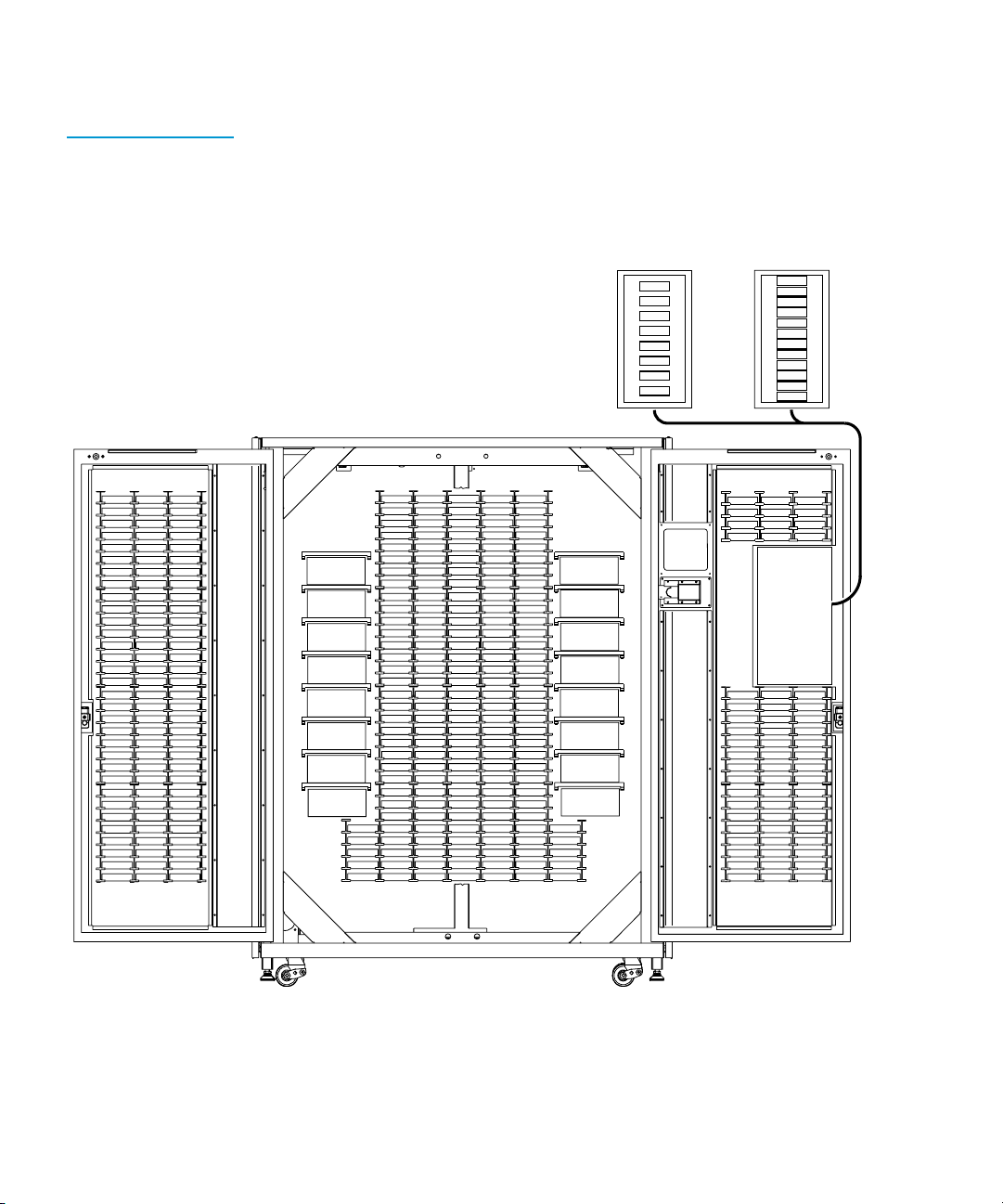
Figure 1
shows the storage bin, load port bin, and tape drive
numbering conventions. These conventions are used by the library
GUI and the diagnostic software program.
Quantum|ATL P3000 Series User’s Guide 3
Page 24
Chapter 1 Library Description
Overview
Figure 1 Bin Shelf
Numbering
Conventions
DLT and/or DLT and/or
LTO SD LT
0
1
2
3
4
5
6
Load Port Bin Numbers
7
0
1
2
3
4
5
6
7
8
9
Load Port Bin Numbers
10
11
294
262
230
263
231
232
233
234
235
236
237
238
239
240
241
242
243
244
245
246
247
248
249
250
251
252
253
254
255
256
257
258
259
260
261
295
296
264
297
265
298
266
299
267
300
268
301
269
302
270
303
271
304
272
305
273
306
274
307
275
308
276
309
277
310
278
311
279
312
280
313
281
314
282
315
283
284
316
285
317
318
286
319
287
320
288
321
289
322
290
323
291
324
292
325
293
Drive Bay 0
Drive Bay 1
Drive Bay 2
Drive Bay 3
Drive Bay 4
Drive Bay 5
Drive Bay 6
Drive Bay 7
005
006
007
008
009
010
011
012
013
014
015
016
017
018
019
020
021
022
023
024
025
026
027
028
029
030
031
032
000
001
033
002
034
003
035
004
036
069
037
070
038
071
039
072
040
073
041
074
042
075
043
076
044
077
045
078
046
079
047
080
048
049
081
050
082
051
083
052
084
053
085
054
086
055
087
088
056
057
089
090
058
091
059
092
060
061
093
062
094
095
063
064
096
097
065
098
066
067
099
100
068
133
101
134
102
103
135
136
104
137
105
138
106
107
108
109
110
111
112
113
114
115
116
117
118
119
120
121
122
123
124
125
126
127
128
129
130
131
132
Drive Bay 8
139
140
141
Drive Bay 9
142
143
144
Drive Bay 10
145
146
147
Drive Bay 11
148
149
Drive Bay 12
150
151
152
Drive Bay 13
153
154
155
Drive Bay 14
156
157
Drive Bay 15
158
159
160
165
161
166
162
167
168
163
169
164
170
171
172
173
174
175
176
177
178
179
180
181
182
183
184
185
186
187
188
189
190
191
192
193
Load
Port
194
195
196
197
198
199
200
201
202
203
204
205
206
207
208
209
210
211
212
213
214
215
216
217
218
219
220
221
222
223
224
225
226
227
228
229
4 Quantum|ATL P3000 Series User’s Guide
Page 25

Chapter 1 Library Description
Features and Benefits
Features and Benefits
The P3000 provides the following features and benefits:
• High-capacity, high-performance data storage and retrieval
• The library may house up to 326 tape cartridges in
configurations with up to 16 tape drives
• Expandable library configurations
• Up to five P2000 and/or P3000 libraries can be joined together
into one virtual library, which enables tape cartridge sharing
between libraries using Quantum|ATL’s Pass Through
Mechanism (PTM)
• Access to future expandability and technology upgrades
through Quantum|ATL’s Prism™ architecture
• Prism architecture employs standard PCI bus technology to
provide greater upgrade flexibility at reduced costs
• This technology ensures compatibility with future on-
board technologies such as tape drive controllers, highspeed host and network interfaces, as well as server and
tape RAID
1
• Reliable, versatile 120-240 volt AC auto-switching power
supplies
• Hot-swappable, redundant DC power supplies ensure library
operations against power supply failure
• An optional advanced cooling system is available to prevent
failures from overheating
• On-line cartridge exchanges: load port with two removable,
6-cartridge magazines for easy insertion of cartridges without
interrupting library operations
• Easy serviceability and manageability
• Hot-swappable drives, DC power supplies, and fans enable
field service engineers to make repairs without taking the
library off-line
Quantum|ATL P3000 Series User’s Guide 5
Page 26

Chapter 1 Library Description
Library Components
• Easy access and replacement of critical components
• A user-friendly GUI provides a wide range of
configuration and service-related functions
• WebAdmin™ provides library access through the Internet
Library Components
The P3000 consists of these major components:
•Cabinet
•GUI
• Intelligrip™ mixed-media CHM
• Mixed-media tape drives (DLT and SDLT, or DLT and LTO)
•Load port
The cabinet houses all library components including:
Cabinet
1
•CHM
•Storage bins
• Control electronics
• Power supply and distribution equipment
•Fan modules
1
• Tape drives
You can access these components to monitor and control library
operation through the front doors and back panels of the library
cabinet.
6 Quantum|ATL P3000 Series User’s Guide
Page 27
Chapter 1 Library Description
Library Components
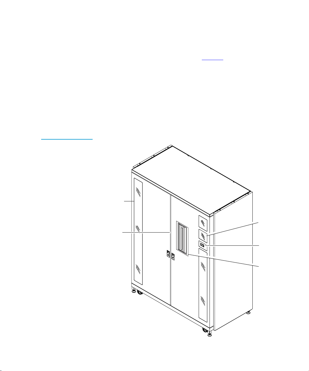
Figure 2 CabinetFront View
Front Panel
The front of the library cabinet (see figure 2
) provides the
following:
• Two front doors provide easy access to the CHM and the
storage array
• The viewing window makes it possible to visually monitor
library operations
• A GUI on the right side of the cabinet enables you to monitor
and control library operations
Viewing
window
1
Dual
doors
Quantum|ATL P3000 Series User’s Guide 7
GUI
Power
switch
Load
port
Page 28
Chapter 1 Library Description
Library Components
• A mixed media load port equipped with either two 8-cartridge
• The power switch for the library is located behind a sliding
stationary load packs for libraries configured with LTO tape
drives, or two 6-cartridge removable load pack magazines for
DLT and/or SDLT tape drives, provides easy insertion of
additional tape cartridges while the library is in operation.
panel on the right front door
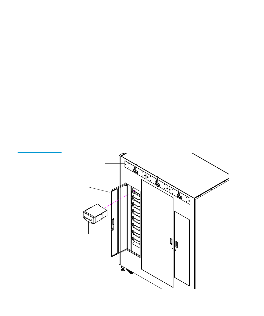
Figure 3 Cabinet Back Panels
Cabinet-Back
The back of the cabinet (see figure 3
) provides easy accessibility to:
• Cooling fans
• Power, control, and data interfaces
• Tape drives
Hot swap,
removable fans
Easy-access
panel
Hot-swappable
drives in
removeable
cannisters
1
8 Quantum|ATL P3000 Series User’s Guide
Page 29
GUI
Chapter 1 Library Description
Library Components
The GUI features a menu system for determining library status,
1
configuring the library, and performing certain diagnostic
functions.
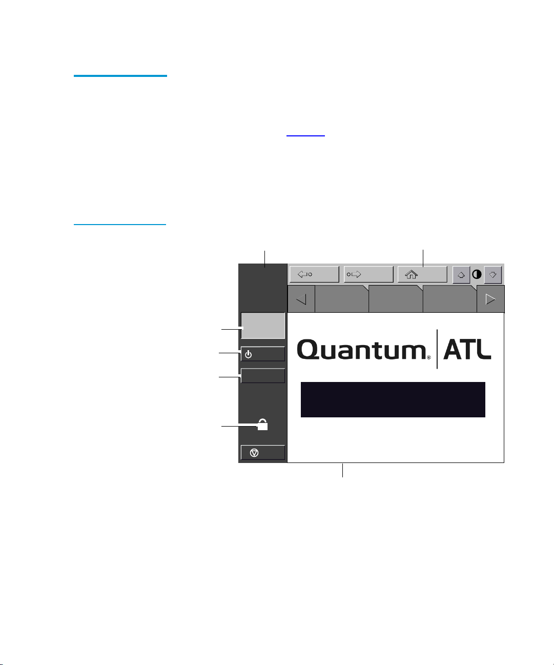
Figure 4 GUI—Initial
Screen
The GUI screen (see figure 4
) consists of:
• Horizontal taskbar (top row)
• Vertical taskbar (left column)
•Main display area
Vertical
task bar
Back Forward
About
System
state
display
Standby
Load
port
Security
indicator/
switch
Quantum|ATL
System
Off-line
Standby
Load Port
U
Overview Tapes Operator
P3000
Horizontal
task bar
Home
Stop
Main display area
The horizontal taskbar provides left and right arrow buttons to
scroll through the tabs for status, configuration, diagnostic, and
operating controls options.
The vertical taskbar provides various library controls:
• System state display - indicates current tasks and requests in
process
Quantum|ATL P3000 Series User’s Guide 9
Page 30
Chapter 1 Library Description
Library Components
• Standby - takes the library “off-line” or “on-line”
• Load port button - submits request to the library to open the
• Security level indicator - shows “locked” on start-up and
• Stop button - immediately removes power from the library
load port
initialization (default)
robotics.
IntelliGripTM Mixed Media CHM
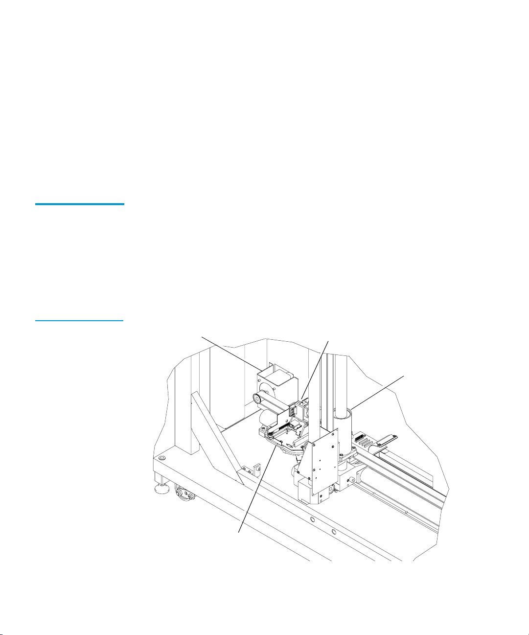
Figure 5 Advanced
Robotics System
The CHM of the library consists of the following components:
1
• Mixed media gripper assembly
• Vertical carriage assembly
• Horizontal drive motor
• Extension axis assembly
Horizontal drive
motor
Mixed media
gripper assembly
Vertical carriage
assembly
Extension access
assembly
10 Quantum|ATL P3000 Series User’s Guide
Page 31

Chapter 1 Library Description
Library Components
The vertical and horizontal actuators move the mixed media
gripper into position to pick and place tape cartridges. The rotary
actuator rotates the mixed media gripper 180 degrees, allowing the
mixed media gripper to pass cartridges between the front storage
bins and the back storage bins or tape drives. The extension
actuator extends the mixed media gripper forward to make contact
with the desired cartridge and then retracts the mixed media
gripper to remove the cartridge from a bin or drive.
The mixed media gripper includes a Class II aser bar code scanner
that reads standard six-character, 3 of 9 bar code labels. The
scanner is used to maintain an inventory of the tape cartridges
within the library. An inventory occurs automatically whenever
the library is turned on or after the bulk load door has been closed.
An inventory can also be initiated from the host computer.
Although the library does not require tape cartridges to have bar
code labels, properly labeled tape cartridges and full storage bins
speed up the inventory process.
Tape Drives
Table 4 Tape Drive
and Cartridge
Specifications
Tape
Cartridge
Quantum
DLT 8000
IBM LTO
Ultrium T200
Quantum
SDLT
The P3000 holds up to 16 tape drives, including combinations of
1
DLT and SDLT, or DLT and LTO.
Cartridge
Transfer
Rate
6 GB/sec 40 GB 80 GB 13.04 TB 26.08 TB
15 GB/sec 100 GB 200 GB 32.60 TB 65.20 TB
11 GB/sec 110 GB 220 GB 35.86 TB 71.72 TB
Cartridge
Capacity
Quantum|ATL P3000 Series User’s Guide 11
Capacity
(compressed)
Total Library
Capacity
(326 bins)
Library
Capacity
(compressed*)
Page 32

Chapter 1 Library Description
Library Components
Note:
* Compressed capacity assumes a 2:1 compression ratio.
When fewer than 16 tape drives are installed, the tape drives must
occupy consecutive drive bays, beginning with drive bay 0.
The drives used in the P3000 are more reliable than standard
drives due to the automated environment.
The P3000 can be populated simultaneously with DLT, SDLT, or
LTO tape drives.
If a drive experiences read/write errors when the AutoClean
function is enabled, the library issues an error message stating that
drive cleaning is required. Without user intervention, the
IntelliGrip CHM replaces the data cartridge with a cleaning
cartridge. When the cleaning procedure finishes, the CHM returns
the data cartridge to the drive.
Note:
When a DLT cleaning cartridge has completed its 20-use
limit, it is automatically exported from the library,
requiring a new one to be loaded through the load port.
Load Port and Magazines
The load port is a mechanical device in the front panel of the
1
library that enables you to import or export tape cartridges to and
from the library via two tape cartridge magazines without
interrupting library operations.
The DLT/SDLT load port uses two removeable 6-bin tape
cartridge magazines (see figure 6
).
The LTO load port uses two stationary 4-bin tape cartridge
magazines (see figure 7
12 Quantum|ATL P3000 Series User’s Guide
).
Page 33

Figure 6 DLT/SDLT
A
F
L 0 5 3
Load Port
Figure 7 LTO Load
Port
Metal
tab
Chapter 1 Library Description
Library Components
Metal tab
6-bin
magazine
DLT/SDLT
cartridge
Load port
assembly
LTO
cartridge
Stationary
4-bin
magazine
Load port
assembly
Quantum|ATL P3000 Series User’s Guide 13
Page 34

Chapter 1 Library Description
Library Components
14 Quantum|ATL P3000 Series User’s Guide
Page 35

Chapter 2
2
Basic Library Operations
This chapter provides an overview of the graphical user interface
(GUI) and describes the following basic library operating
procedures:
• Installing tape cartridges
• Preparing the library for operation
• Turning the library on and off
•Using the GUI
• Obtaining library status
• Changing the GUI security level
• Operating the load port
• Inserting tape cartridges
• Manually ejecting a cartridge
Quantum|ATL P3000 Series User’s Guide 15
Page 36

Chapter 2 Basic Library Operations
Installing Tape Cartridges
Installing Tape Cartridges
To install tape cartridges
Label each cartridge
1
Set the write-protect switch
2
Place cartridges in the fixed bins
3
Handle tape cartridges with care. Do not drop or
bang them, or place them near sources of
electromagnetic interference. Rough handling can
displace the tape leader, making the cartridge
unusable and potentially hazardous to the tape
drives.
Taking ESD Precautions
Caution:
Components within the P3000 contain static-sensitive parts. To
2
prevent damage to these parts while performing installation,
maintenance, or replacement procedures, observe the following
precautions:
2
• Keep the library turned off during all installation,
maintenance, and replacement procedures.
Note:
Hosts without a direct SCSI interface require external
communications bus converters.
• Keep the library power cord connected to a grounded power
outlet except when working with AC electrical components.
Warning:
Avoid contact with the power supplies, EMI
filter, and all other AC electrical components
while the library is connected to a power outlet.
16 Quantum|ATL P3000 Series User’s Guide
Page 37

Chapter 2 Basic Library Operations
Installing Tape Cartridges
• Use an antistatic wrist strap when touching internal library
components. To use the wrist strap properly, place the band
around your wrist and attach the clip to the library frame. Keep
the strap on until you are ready to close the library doors.
• Keep static-sensitive parts in their shipping containers until
ready for installation.
• Do not place static-sensitive parts on any metal surface. If you
need to put down a static-sensitive part, place it inside its
protective shipping bag or on a grounded antistatic mat.
• Avoid direct contact with static-sensitive parts. Avoid touching
connectors and discrete components.
• Close library door and access panel when not working on the
library.
• Be very careful when installing the library or handling
components in dry climates or environments where cold
weather heating is used. Environments such as these with
lower relative humidity have greater potential to produce
static electricity.
DLT/SDLT Cartridges
Note:
In environments with high potential for static
electricity, you may want to take additional
precautions such as the use of an antistatic smock or
a grounded antistatic mat.
The following shows you how to label DLT/SDLT tape cartridges,
2
as well as setting the write-protect switch and proper orientation.
Labeling
Attaching a bar code label to each tape cartridge enables the library
to identify the cartridge quickly, thereby speeding up inventory
time.
Place the label in the slide-in slot on the front of the cartridge (see
figure 8
).
Quantum|ATL P3000 Series User’s Guide 17
2
Page 38

Chapter 2 Basic Library Operations
Installing Tape Cartridges
Figure 8 Inserting a
Bar Code Label (DLT/
SDLT)
Slide-in slot
Note:
Only use bar code labels that have been designed
for cartridges. Do not adhere labels to a cartridge
anywhere except the slide-in slot.
Setting the Write-Protect Switch
Each tape cartridge has a write-protect switch similar to that
shown in figure 9
. This switch determines whether new data can
be written to the cartridge (write-enabled) or whether data on the
cartridge is protected from being erased or overwritten (write-
protected).
Proper Insertion Orientation
Refer to figure 9
for proper label placement, write protection
settings and insertion orientation.
2
2
18 Quantum|ATL P3000 Series User’s Guide
Page 39

Figure 9 DLT and
SDLT Cartridges
Chapter 2 Basic Library Operations
Installing Tape Cartridges
Insert this end into the bin
LTO Cartridges
A F L 0 5 3
Insertion arrow
DLTtape IV
Barcode label
Orange
window
LTO tape cartridges are different in size to the DLT/SDLT
2
Write
protect
Slide left Slide right (default)
Write
enable
(DLT cartridge shown)
cartridges as well as in the barcode labeling and write-protect
switch setting.
Adhesive-backed bar code labels are used on LTO tape cartridges.
Refer to figure 10
for proper label placement, write protection
settings and insertion orientation.
Quantum|ATL P3000 Series User’s Guide 19
Page 40

Chapter 2 Basic Library Operations
Preparing the Library for Operation
Figure 10 LTO
Cartridge
Write Protect
Switch
Slide left
(default)
Write
enable
Write
protect
Slide right
A B C 1 2 3 L 1
Caution:
Insert this end into the bin
Insertion arrow
Barcode label
LTO tape drive media cannot be degaussed due to
the fact that it uses "magnetic servos". Do not attempt
to degauss LTO tape drive media. If this media is
degaussed, it will no longer work.
Placing Tape Cartridges in the Library
Place a tape cartridge in each fixed storage bin on the back wall of
the library and on the inside of the front doors. Be sure all
2
cartridges are properly oriented with the barcode facing you and
that they are fully seated in the bins.
Preparing the Library for Operation
To prepare the library for operation:
• Close the library doors and access panels
• Connect the host workstations
20 Quantum|ATL P3000 Series User’s Guide
2
Page 41

Chapter 2 Basic Library Operations
Preparing the Library for Operation
Closing the Library Doors and Access Panels
Connecting Host Workstations
The library has two front doors and three back access panels.
Close and lock the front doors.
1
2
Close one door and then the other.
a
Turn the door latches to secure the doors to the library
b
frame.
Lower the latches over the door locks.
c
Using the key from the accessory kit, lock the latches in
d
place.
Close and lock the back access panels using a 5/32 hex wrench
2
(not provided).
Connect the SCSI cables and jumpers as shown in the applicable
2
figures.
Note:
Quantum|ATL ships sufficient SCSI cables and
terminators with this library to set up two-drives per
SCSI bus, as well as adequate SCSI jumper cables to
accommodate up to 4 drives per SCSI bus.
Figure 11
shows the recommended cabling configurations for the
16-drive library.
Quantum|ATL P3000 Series User’s Guide 21
Page 42

Chapter 2 Basic Library Operations
Preparing the Library for Operation
Figure 11 Cabling
Configuration 16 Drive
Drive Column 1
Tape drive
Drive position 8
SCSI ID 2
Tape drive
Drive position 9
SCSI ID 3
Tape drive
Drive position A
SCSI ID 4
Tape drive
Drive position B
SCSI ID 5
tape drive
Drive position C
SCSI ID 2
Tape drive
Drive position D
SCSI ID 3
Tape drive
Drive position E
SCSI ID 4
Tape drive
Drive position F
SCSI ID 5
6310777-01
Library electronics
SCSI ID 0
Drive Column 0
Tape drive
Drive position 0
SCSI ID 2
Tape drive
Drive position 1
SCSI ID 3
Tape drive
Drive position 2
SCSI ID 4
Tape drive
Drive position 3
SCSI ID 5
Tape drive
Drive position 4
SCSI ID 2
Tape drive
Drive position 5
SCSI ID 3
Tape drive
Drive position 6
SCSI ID 4
Tape drive
Drive position 7
SCSI ID 5
0415619
SCSI diff. terminators
8 PLS
6310772-01
8 PLS
SCSI Port Q
SCSI Port R
SCSI Port A
SCSI Port B
SCSI Port P
6310773-04
6310773-04
6310773-03
6310773-03
6310773-02
6310773-02
6310773-01
6310773-01
SCSI Port O
SCSI Port N
SCSI Port M
SCSI Port L
SCSI Port K
SCSI Port J
SCSI Port I
6310772-02
SCSI Port C
22 Quantum|ATL P3000 Series User’s Guide
SCSI Port H
SCSI Port G
SCSI Port F
SCSI Port E
SCSI Port D
6310773-04
6310773-04
6310773-03
6310773-03
6310773-02
6310773-02
6310773-01
6310773-01
Page 43

Chapter 2 Basic Library Operations
Turning the Library On and Off
Turning the Library On and Off
This section explains how to:
•Turn on the library
• Place the library on-line or off-line
• Turn off the library
• Test the installation
Turning On the Library
To turn on the library:
2
Verify that:
1
• Power cables are firmly in place
• All doors are closed
Turn on the power switch located behind the small sliding
2
door below the GUI.
After several seconds, verify that the current state of the library
3
(“System On-line” or “System Off-line”) appears in the System
State display on the GUI (see figure 12
2
).
Placing the Library On-line or Off-line
Turning Off the Library
With the library turned on, press the Standby button on the GUI.
2
Pressing the Standby button toggles the library between on-line
and off-line states.
To turn off the library:
2
Place the library off-line by pressing the Standby button.
1
The library robotics completes any current commands and then
stops.
Verify that the GUI display indicates “System Off-line.”
2
Quantum|ATL P3000 Series User’s Guide 23
Page 44

Chapter 2 Basic Library Operations
Using the GUI
Verify that the CHM is empty by checking the Overview screen
3
on the GUI (see chapter 3,
If there is a tape cartridge in the CHM, perform a Move
command to place the cartridge in an available bin.
Turn off the power switch located below the GUI.
4
Operator Commands).
Using the GUI
Note:
Wait ten seconds before turning on the power switch
again.
The GUI is activated by touching the screen, and is located on the
front of the library. The menus displayed on the GUI allow you to
obtain information about the library, execute library commands,
and test library functions (see figure 12
).
The GUI’s functions are grouped into the following four screens:
• Overview screen—displays current tape drive, CHM, and load
port content and activities.
• Tapes screen—displays tape drive, storage bin, load port, and
gripper inventories.
• Operator screen—contains library configuration and control
functions (password protected).
2
• Service screen—contains reporting functions, system tests, and
service commands (password protected).
• Multi-Unit screen—contains multi-unit configuration and
calibration.
24 Quantum|ATL P3000 Series User’s Guide
Page 45

Chapter 2 Basic Library Operations
Using the GUI
Figure 12 GUI—Initial
Screen
Back Forward
Home
About
Quantum|ATL
System
Off-line
Standby
Load Port
Overview Tapes Operator
P3000
U
Stop
Table 5 lays out the various functions of the GUI.
Quantum|ATL P3000 Series User’s Guide 25
Page 46

Chapter 2 Basic Library Operations
Using the GUI
Table 5 GUI
Components
Overview
Screen
Status display
• Tape drives
• Activity
• Load port
Tapes
Screen Operator Screen* Service Screen* Multi-Unit*
Inventory
display
• Tape
drives
• Storage
bins
• Load port
• Transport
(CHM)
Configure
• Configure Library
• Configure Options
• Control
• Move Cartridges
• Inventory Tapes
• Calibrate Library
• Unload Drive
• Unload Imp/Exp
(CHM)
Reports
• Statistics
• Actuator
• SysTest Results
• Auto Clean
• Tests
• SysTest Library
• Miscellaneous
• Initialize
Nonvol Stats
Configuration
Calibration
• Initialize
Nonvol Config
• Change
Password
*These screens are password protected.
Opening a Screen
To open one of the four main screens, touch the desired tab at the
2
top of the GUI. The Overview and Tapes screens are accessible to
any user. The Operator and Service screens require a password.
Once the desired screen appears on the GUI, you can view
information or press buttons to execute commands and open other
screens.
Library Status Information
26 Quantum|ATL P3000 Series User’s Guide
Some information about the library firmware version, security
2
status, and library status can be found on the left side of the GUI.
Page 47

Chapter 2 Basic Library Operations
Using the GUI
• Company logo—displays a company information screen when
pressed, as well as the application level and boot block level.
• System state display—shows the current state of the library
(system on-line, system off-line, system stopped, door open,
and so on).
• Lock icon—shows the current security level at the GUI. Five
security levels are available: service (S), operator (O), user (U),
import only (I), and locked (L). Table 6
describes the attributes
of each security level.
Figure 13 Library
Status Indicators
Exiting a Screen
Company logo
Back Forward
Home
About
System
state
display
Quantum|ATL
System
Off-line
Standby
Load Port
Overview Tapes Operator
P3000
Lock
icon
To exit any screen, press the Back or Home button.
2
While the command is executing, the GUI displays a Command In
Progress dialog box with an Abort button. Pressing Abort cancels
the command and stops the ongoing operation.
U
Stop
After pressing Abort, it is still necessary to press the Back button to
exit the screen associated with the aborted command.
Quantum|ATL P3000 Series User’s Guide 27
Page 48

Chapter 2 Basic Library Operations
Using the GUI
Library controls are located along the top and left side of the GUI
Library Controls
2
in the horizontal and vertical bars (see figure 14
).
Figure 14 Library
Controls
Back Forward Home
Back Forward
About
Standby
button
Load Port
button
Quantum|ATL
System
Off-line
Standby
Load Port
Overview Tapes Operator
P3000
U
Stop
button
These controls function as follows:
• Home button—returns to the home (initial) screen.
Stop
Contrast
Home
• Forward button—moves forward screen by screen through
previous selections.
• Back button—moves backward screen by screen through
previous selections.
• Contrast buttons—adjust the contrast of the GUI screen.
• Standby button—toggles the library between on-line and offline states.
• Load Port button—releases and locks the load port door. If the
load port is locked in the closed position, pressing this button
releases the load port and then locks the door. If the load port is
28 Quantum|ATL P3000 Series User’s Guide
Page 49

Chapter 2 Basic Library Operations
Obtaining Library Status
locked in the open position, pressing this button unlocks the
load port, allowing you to rotate the load port to the closed
position where it automatically locks.
• Stop button—halts library activity immediately by cutting
power to library robotics. Pressing the Stop button a second
time restores power to library robotics.
Note:
The default passwords are:
• Service “5678”
• Operator “1234”
• User “2222”
• Import Only “1111”
For more information on password and security levels, refer to
Changing the GUI Security Levels
Obtaining Library Status
The Overview and Tapes screens on the GUI provide library
status. The Overview screen displays a “snapshot” of the tape
drive, robot activity, and load port inventory (see figure 15
Tapes screen displays the inventory of all elements in the library
(see figure 17
).
on page 33.
2
). The
Overview Screen
To display the Overview or Tapes screen, press the appropriate tab
on the GUI.
The Overview screen provides information for the following items:
2
•Drives
•Activity
•Load port
Quantum|ATL P3000 Series User’s Guide 29
Page 50

Chapter 2 Basic Library Operations
Obtaining Library Status
Figure 15 Overview
Screen
About
Quantum|ATL
System
Off-line
Standby
Load Port
U
Stop
Back Forward
Overview Tapes Operator
Drives Activity Load Pack
D00
ANF 120
Ready
D01
???
Ready
D02
empty
Ready
D03
ANF 123
Ready
GRP
empty
Home
P00
ANF146
P01
ANF147
P02
ANF148
P03
ANF149
Cartridge
Element
present
number
Bar code
number
Write-
Element
status
D03
ANF 123
Ready
enabled
Compression
enabled
Drives
The Drives area reports whether:
• A tape drive contains a tape cartridge
• The tape cartridge is write-enabled or write-protected
• Compression is enabled
It also displays the bar code number of the cartridge.
For a more detailed screen showing an individual drive’s status,
press the screen anywhere in the Drives area to display the Tape
30 Quantum|ATL P3000 Series User’s Guide
2
Page 51

Chapter 2 Basic Library Operations
Obtaining Library Status
Drive Status screen (see figure 16). Use the arrow buttons at the
bottom of the screen to scroll to the desired drive.
Figure 16 Tape Drive
Status Screen
About
Quantum|ATL
System
Off-line
Standby
Load Port
U
Stop
Back Forward
TapesOverview Operator ServiceOverview
Tape Drive Status
D03
D00
ANF 123
ANF 120
Ready
DLT 8000 SCSI ID: 05
D02
CompacTape IV, 35/70 Gb
???
Drive Code Rev: 000037
Ready
Controller Code Rev: 96
S/N: JF71100038
Ready
D01
Compression ON
Write Protect OFF
EMPTY
Ready
D03
ANF 123
Ready
Home
Prevent: OFF
Cleaning Required: OFF
Cleaning Requested: OFF
Tape Remain: 033729 MB
Compr Ratio (R): N/A
Compr Ratio (W): N/A
Clean Cart Loads: 0000005
Hrs Since Cleaned: 00326
Clean Tape Used 000 times
To return to the Overview screen, press the screen anywhere in the
Tape Drive Status box.
Activity
2
The Activity area shows the source element, the transport medium,
and the destination element involved in the activity; the current
location of the tape cartridge; and the progress of the activity.
Load Port
The Load Port area identifies tape cartridges currently stored in
either magazine in the load port. Use the arrow button to view
contents not currently displayed.
Quantum|ATL P3000 Series User’s Guide 31
2
Page 52

Chapter 2 Basic Library Operations
Obtaining Library Status
The Tapes screen identifies the tape cartridges residing in the
Tapes Screen
2
following elements:
•Drives
• Storage (fixed storage bins)
•Load port
• Transport (gripper)
Figure 17 Tapes
Screen
Viewing Storage and Load Port Elements
The Drives, Storage, and Load Port categories may contain too
many elements to display at once. To scroll through these
elements, use the arrow buttons at the bottom of each category.
You can also expand the Drives, Storage, or Load Port list to fill the
screen by touching the desired category anywhere above the
scrolling arrows. To return to the start of the Tapes screen, press
the
Back
button.
32 Quantum|ATL P3000 Series User’s Guide
2
Page 53

Chapter 2 Basic Library Operations
Changing the GUI Security Levels
Changing the GUI Security Levels
There are five levels of security for the P3000 GUI (see table 6):
• Service (S)—provides access to both the Operator and Service
set of screens and all functions on the system bar.
• Operator (O)—provides access to the Operator set of screens
and all functions on the system bar.
• User (U)—provides access to screens that are not passwordprotected (Overview and Tapes screens) and all functions on
the status bar.
• Import Only (I)—provides access to Overview and Tapes
screens and the Load Port button on the system bar (no Stop or
Standby).
• Locked(L)—provides access to Overview and Tapes screens
only.
The security level indicator (lock icon) at the lower left corner of
the GUI indicates the current security level (S, O, U, I, or L).
2
Table 6 Security
Levels (listed from
highest to lowest)
.
Level
Lock Icon
Indicator
Password
Protected
Overview
Screen
Access
Tapes
Screen
Access
Operator
Screen
Access
Service
Screen
Access
Load
Port
Access
Service S Yes Yes Yes Yes Yes Yes Yes
Operator O Yes Yes Yes Yes No Yes Yes
User U Yes Yes Yes No No Yes Yes
Multi-
O Yes No No No No No No
Unit
Quantum|ATL P3000 Series User’s Guide 33
Stop and
Standby
Access
Page 54

Chapter 2 Basic Library Operations
Changing the GUI Security Levels
Level
Import
Lock Icon
Indicator
Password
Protected
Overview
Screen
Access
I Yes Yes Yes No No Yes No
Tapes
Screen
Access
Operator
Screen
Access
Service
Screen
Access
Load
Port
Access
Only
Locked L No Yes Yes No No No No
When the User security level is set, access is restricted to the
Securing the GUI
2
Operator and Service screens. Since these screens control library
configuration, testing, and initializing functions, the User security
level is appropriate default condition for routine library operation.
Changing Security Levels
To change security levels:
Press the Lock icon.
1
The Password screen appears (see figure 18
Press the desired security level button (Service, Operator, User,
2
).
Import Only, or Locked).
Stop and
Standby
Access
2
34 Quantum|ATL P3000 Series User’s Guide
Page 55

Chapter 2 Basic Library Operations
Changing the GUI Security Levels
Figure 18 Password
Screen
About
Quantum|ATL
System
Off-line
Standby
Load Port
O
Stop
Enter a password if necessary.
3
Back Forward
Operator
Enter Password
Enter Password: _
Tapes
Home
Service
1 2
3 4
5 6
7 8
9 0
Enter
A password is required to enter a higher security level than the
current level.
Press the Select button.
4
A screen appears indicating that the new security level has
been set successfully.
Press Okay.
5
The lock icon displays the new security level (S, O, U, I, or L).
Note:
This procedure is especially useful to change from
Operator or Service levels to the User level after
executing an Operator or Service level command.
Note:
If the GUI is accessed from the Service (S) or
Operator (O) level, and no activity has occurred for
15 minutes, the GUI will return to the initial screen
(see figure 12
Quantum|ATL P3000 Series User’s Guide 35
).
Page 56

Chapter 2 Basic Library Operations
Operating the Load Port
Operating the Load Port
After pressing the Load Port button on the GUI, the library will
release the lock on the load port (you will hear an audible ‘click’).
The GUI displays “Wait Open Load Port.” Pull on the load port’s
handle. The load port pulls outward about an inch to its unlocked
position which allows its interior drum to be rotated 180
magazine loading or unloading.
Warning:
After loading or unloading the magazines, rotate the load port
back 180
position.
Note:
Opening or closing the load port door presents
mechanical hazards. Use both hands to pull or push
the load port finger grip and use the top and bottom
surfaces of the load port drum to keep fingers out of
load port openings when rotating the load port drum
(see figure 19
o
and push the load port handle to lock the load port into
The mixed media load port used with LTO tape
cartidges has two stationary 4-cartridge magazines built
into the load port, unlike the two removable 6-cartridge
magazines used with DLT and SDLT tape cartridges. If
the library contains both DLT and LTO tape drives, the
stationary magazines are used in the load port.
).
o
for
2
Removing/ Installing a Tape Cartridge Magazine
36 Quantum|ATL P3000 Series User’s Guide
To remove a DLT/SDLT magazine from the load port, press up on
the metal tab at the upper right corner of the load port bay. Rotate
the magazine handle from the top of the magazine toward you and
2
pull the magazine from the loadport. Reverse this procedure to
install a magazine (see figure 6
on page 13).
Page 57

Chapter 2 Basic Library Operations
Inserting Tape Cartridges into the Load Port
Loading a Tape Cartridge Magazine
The magazine used with DLT/SDLT tape cartridges have keyed
bins to prevent improper cartridge insertions. They are equipped
2
with spring-loaded mechanisms to capture or release a tape
cartridge.
To insert a tape cartridge, push it into the magazine’s bin until you
here a click and the metal tab at the left side of the bin pops out.
To remove a tape cartridge, gently push the cartridge all the way
into the bin, then release. The cartridge will be partially ejected,
making it easy to remove.
Inserting Tape Cartridges into the Load Port
This section explains how to insert tape cartridges using the load
port mechanism.
Caution:
Do not use CompacTape I, CompacTape II, or
CompacTape IIIXT cartridges in this library.
2
Inserting DLT and SDLT Tape Cartridges
DLT/SDLT tape cartridges are inserted into two removeable 6cartridge magazines as shown in figure 6
2
cartridges may be loaded to or unloaded from a magazine with the
on page 13. Tape
magazine in or out of the library.
To insert a DLT tape cartridge into a magazine:
Note:
1
To move cartridges to the load port for removal, refer to
Moving Cartridges
on page 50.
Prepare the tape cartridges to be inserted by affixing a bar code
label and write-protecting or write-enabling each cartridge as
desired.
Quantum|ATL P3000 Series User’s Guide 37
Page 58

Chapter 2 Basic Library Operations
Inserting Tape Cartridges into the Load Port
For more information about these procedures, refer to
Installing Tape Cartridges
With the load port door open, place the tape cartridges in any
2
available load port magazine slot (see figure 20
If the magazine is out of the load port, load the tape cartridges
3
into the magazine, then load the magazine into the load port.
The proper orientation for tape cartridge insertion is shown in
DLT/SDLT Cartridges
page 19.
Rotate the load port drum 180o so that the load port handle
4
faces you (see figure 19
Figure 19 Rotating
the Load Port Drum
on page 16.
).
on page 17 and LTO Cartridges on
).
Load port
finger grip
Warning:
Take care to keep fingers out of load port
openings when opening or closing the load port
door or when rotating the load port drum.
Manually close the load port door by pushing the load port
5
assembly so that it is flush with the front surface of the library.
You will hear a “click” when it locks into position.
Load
port
drum
38 Quantum|ATL P3000 Series User’s Guide
Page 59

Chapter 2 Basic Library Operations
Inserting Tape Cartridges into the Load Port
If Auto Load is enabled, the library automatically moves the
cartridges to available bins.
Ins erting LTO Tape Cartridges
Figure 20 LTO Tape
Cartridge Load Port
To insert an LTO cartridge:
2
The two load port magazines used when LTO tape drives are
1
present in the library are stationary and built into the load port.
They accommodate up to 8 LTO or DLT tape cartridges. The
magazines employ no loading mechanism (unlike the DLT
removeable magazines) and tape cartridges are simply placed
into the bins with the barcodes facing out and the write-protect
switch on the left (see figure 20
).
Loadport
assembly
Barcode
Write-protect
switch
Stationary
magazine
Quantum|ATL P3000 Series User’s Guide 39
Page 60

Chapter 2 Basic Library Operations
Manually Ejecting a Tape Cartridge
Manually Ejecting a Tape Cartridge
To manually eject a tape cartridge from a DLT tape drives:
DLT Tape Drives
2
Open one or both of the library front doors:
1
Press the Standby button on the GUI. This places the library
a
off-line.
Verify that the display state display reads System Off-line
b
and that the robotics has stopped moving. The off-line state
does not take effect until current commands are completed.
Take electrostatic discharge precautions as explained in
c
Taking ESD Precautions
Using the key from the accessories kit, unlock each door.
d
Lift each door handle straight up and then turn the handle
e
on page 16.
counterclockwise to unlatch each door.
Gently pull on each door handle to open the door.
f
Press the Unload button on the drive (see figure 21).
2
When you press Unload, the tape cartridge rewinds. This may
take between 10 to 120 seconds. When the rewind process is
completed, the Operate Handle indicator comes on.
2
Figure 21 DLT Tape
Drive Front Bezel
(Example)
40 Quantum|ATL P3000 Series User’s Guide
Unload button
Insert/release
handle
(shown in up position)
Page 61

Chapter 2 Basic Library Operations
Manually Ejecting a Tape Cartridge
When the Operate Handle indicator comes on, raise the insert/
3
release handle to eject the tape cartridge.
Quantum SDLT and IBM Ultrium LTO Tape Drives
Note:
Place your finger approximately 1/4 of an inch in
front of the drive’s cartridge opening to ensure that
the cartridge does not drop when ejected.
Caution:
Pause for at least 3 seconds, then grasp the tape
cartridge and slowly pull it half way out of the
drive.
Caution:
If the tape cartridge leader failed to detach from
the take-up leader, push the tape cartridge all of
the way back into the drive, press down the
insert/release handle, and return to step 2.
Otherwise, continue to step 5.
Pull the tape cartridge completely out of the drive.
4
Close and lock the library doors.
5
To manually eject a tape cartridge from Quantum SDLT and IBM
Ultrium LTO T200 tape drives:
2
Refer to Steps 1a-1f under DLT Tape Drives on page 40.
1
Press the Unload button on the drive. The Unload button
2
works the same as a soft eject (VCR-style) button.
Quantum|ATL P3000 Series User’s Guide 41
Page 62

Chapter 2 Basic Library Operations
Manually Ejecting a Tape Cartridge
42 Quantum|ATL P3000 Series User’s Guide
Page 63

Chapter 3
3
Operator Commands
This chapter describes the commands found on the Operator
screen of the graphical user interface (GUI). The Operator screen
commands initiate the following actions:
• Opening the Operator screen
•Unloading the load port
• Configuring the library*
• Configuring library options*
•Performing an inventory*
• Moving cartridges*
• Unloading a drive*
*
The library must be off-line to perform these functions.
Caution:
Quantum|ATL P3000 Series User’s Guide 43
Library operator commands are to be used only by
qualified, Quantum|ATL-trained personnel. Serious
operational problems and data loss may occur if you
do not understand the consequences of these
commands.
Page 64

Chapter 3 Operator Commands
Opening the Operator Screen
Opening the Operator Screen
To open the Operator screen:
Press the Operator tab.
1
The GUI displays the password screen (see figure 22
Enter the correct operator or service password to gain access to
2
the Operator Screen (see figure 23
The default operator password is 1234.
Note:
Figure 22 Password
Screen
To change passwords, see Press Continue. A
“Command in Progress” dialog screen is displayed.
on page 64.
3
).
).
44 Quantum|ATL P3000 Series User’s Guide
Page 65

Chapter 3 Operator Commands
Configuring the Library
Figure 23 Operator
Screen
About
Quantum|ATL
System
Off-line
Standby
Load Port
O
Stop
Back Forward
Overview Tapes Operator
Config.
Configure
Library
Configure
Options
Control
Move
Cartridges
Inventory
Tapes
Home
Calibrate
Library
Unload
Drive
Unload
Imp/Exp
Configuring the Library
The Configure Library command allows you to assign the
following:
• Library model number
• Number of storage bins
• Number of drives
• Library SCSI ID
• Tape drive SCSI ID
To configure any of these attributes use the following procedure.
In the Operator screen, press the Configure Library button.
1
The Configure: Library screen is displayed (see figure 24
Quantum|ATL P3000 Series User’s Guide 45
3
).
Page 66

Chapter 3 Operator Commands
Configuring the Library
Figure 24 Configure:
Library Screen
About
Quantum|ATL
Back Forward
Home
Overview Tapes Operator
System
Off-line
Standby
Load Port
O
Stop
Press the Configure button.
2
Configure: Library
Inquiry: P7000 64xxxxx
Model: 64xxxxx
# Bins: 679
# Drives: 16
Serial Number:
IEEE ID:
Library SCSI ID: 0
Drive 0 SCSI ID: 2
Drive 1 SCSI ID: 3
Drive 2 SCSI ID: 4
Configure
The GUI dispays the Configure: Library Settings screen (see
figure 25
).
Figure 25 Configure:
Library Settings
Screen
About
Quantum|ATL
Back Forward
Overview Tapes
System
Off-line
Standby
Load Port
Configure: Library Settings
Model:
# Bins:
# Drives:
64xxxxx
679
8
Device: Library
O
Stop
SCSI ID: 0
46 Quantum|ATL P3000 Series User’s Guide
Home
Operator
Select
Change
Page 67

Chapter 3 Operator Commands
Configuring Library Options
Press the Select button until you highlight the setting you want
3
to change.
Using the arrow buttons, scroll through available values for the
4
setting.
Press the Change button to accept the new value.
5
Repeat steps 3 through 5 to make other changes.
6
Press the Back button to return to the Configure: Library
7
screen.
The options you selected are now part of the library configuration.
SCSI ID Assignment Guidelines
When selecting SCSI ID numbers, each SCSI device on the same
bus must have a unique number from 0 to 15. SCSI devices include
3
the library robotics, the host computer, the library tape drives,
internal and external hard disk drives, and so on.
If you set up the library with multiple SCSI buses, you can assign
the same number to two or more devices, provided each device is
on a different SCSI bus.
Note:
Power must be cycled for the new SCSI ID number to
become effective.
Configuring Library Options
The Configure Options command allows you to set the following:
• Power-On State—determines whether the library is on-line or in
standby mode when powered up. The default setting is Online.
3
• AutoClean—allows the library to perform drive cleaning tasks
automatically as needed. The default setting is Disabled.
Quantum|ATL P3000 Series User’s Guide 47
Page 68

Chapter 3 Operator Commands
Configuring Library Options
• Retries—causes the library to automatically retry a failed
• Bar Code Labels—turns bar code scanning on or off during
• Auto Inventory—causes the library to perform an inventory
• Auto Load—causes the library to automatically move cartridges
• Temp. Detection—enables or disables the over-temperature
• Power-On Security—determines the library security level when
command before issuing an error message. The default settting
is Enabled.
inventory. It should be disabled when the library contains
cartridges that are not labeled. The default setting is Disabled.
whenever the library is powered up. The default setting is
Disabled.
in the load port to empty storage bins as soon as the load port
door closes. The default setting is Disable.
detection warning and shutdown features of the library. The
default setting is Enabled.
powered up. The default setting is User.
• 4/52 Identity Mode—causes the library to return the same
inquiry string as the ATL 520 library (out of production).
Configuring a Library Option
To configure a library option:
3
In the Operator screen, press the Configure Options button.
1
The GUI displays the Configure: Options screen (see figure 26
Press the button with the desired option.
2
Using the arrow buttons, scroll through available values for the
3
selected option.
When the New Value box displays the desired value, press the
4
Execute button to apply the new value.
The Current Value box displays the new value.
Repeat steps 2 through 4 to change other configuration options.
5
48 Quantum|ATL P3000 Series User’s Guide
).
Page 69

Figure 26 Configure:
Options Screen
Chapter 3 Operator Commands
Performing an Inventory
When you have finished making changes to library options,
6
press the Back button until you return to the initial Operator
Screen.
About
Quantum|ATL
Back Forward
Overview Tapes Operator
Home
System
Off-line
Standby
Load Port
Configure: Options
O
Stop
Performing an Inventory
The Inventory Tapes command reads the bar code labels of the
cartridges in the tape drives, fixed storage bins, and the load port
bins. All elements that contain cartridges without labels are
marked as full with no label.
Power-On
Retries
Barcode
Labels
Auto
Load
Auto Drive
Unload
Auto
Clean
Auto
Inventory
Te mp .
Detection
Power-On
Security
Barcode
Retries
Current
Value:
Set
Storage
Works
Defaults
New Value:
Online
Execute
3
Press the Inventory Tapes button in the Operator screen.
1
The GUI displays a “Command In Progress” screen.
Quantum|ATL P3000 Series User’s Guide 49
Page 70

Chapter 3 Operator Commands
Moving Cartridges
2
Press the Abort button to stop continuous running of the
inventory process, otherwise, the process will continue until all
storage elements have been inventoried.
Note:
Moving Cartridges
The Move Cartridges command allows you to move any tape
cartridge in the library to the destination you specify. This
destination can be a storage bin, a tape drive, the load port, or the
gripper.
Note:
To move a cartridge:
In the Operator screen, press the Move Cartridges button.
1
The GUI displays the Control: Move Cartridges screen, with
the Source input field active (see figure 27
The inventory process is also stopped if an error is
detected. In this case, the GUI displays an error
message.
To move a cartridge from a tape drive, issue an Unload
Drive command as explained in “
Unloading a Drive.”
).
3
50 Quantum|ATL P3000 Series User’s Guide
Page 71

Chapter 3 Operator Commands
Moving Cartridges
Figure 27 Control:
Move Cartridges
Screen
Backspace button:
Use this button to erase a partial
entry - character by character
Back Forward
Home
About
Quantum|ATL
Overview Tape s Operator
System
Off-line
Standby
Load Port
O
Stop
Identify the source element of the cartridge to be moved.
2
Control: Move Cartridge
Source:
Destination:
Range:
_
Execute
Storage Bin
Drive
Load Port
Gripper
PTM
Proceed as follows:
1 2
3 4
5 6
7 8
9 0
Select
Press the appropriate source element button (Storage Bin,
a
Tape Drive, Load Port, or Gripper). When you press an
element type, the Range field (below the Destination field)
displays the range of addresses .
Using the keypad, enter the address of the source element
b
and then press the Destination input field. The Source
information is displayed in the Source field and the
Destination field becomes active.
Identify the destination for the cartridge:
3
Press the appropriate destination element button (Storage
a
Bin, Tape Drive, Load Port, or Gripper).
Quantum|ATL P3000 Series User’s Guide 51
Page 72

Chapter 3 Operator Commands
Unloading a Drive
Using the keypad, enter the address of the destination
b
element and then press the Execute button. The destination
information is displayed in the Destination text box and the
move is initiated.
The GUI displays a Command In Progress dialog box with an
Abort button.
The Move Cartridges command continues until completed
unless you press the Abort button to stop the operation.
Unloading a Drive
The Unload Drive command prepares a tape cartridge to be
removed from a drive by rewinding and ejecting the cartridge.
After unloading the drive, remove the tape cartridge using the
Move Cartridges command.
To unload a drive:
On the Operator screen, press the Unload Drive button.
1
The GUI displays the Control: Unload Drive screen (see
figure 28
3
).
52 Quantum|ATL P3000 Series User’s Guide
Page 73

Figure 28 Unload
Drives Screen
About
Quantum|ATL
Chapter 3 Operator Commands
Unloading the Load Port
Back Forward
Overview Tapes Operator
Home
System
Off-line
Standby
Load Port
O
Use the arrow buttons to highlight the desired drive and then
2
Control: Unload Drive
press Execute.
The GUI displays a Command In Progress dialog box.
The Unload Drive command continues until completed unless
you press the Abort button to stop the operation.
Unloading the Load Port
Drive 0
Execute
3
The Unload Imp/Exp command moves a tape cartridge from the
load port to an available storage bin. This option must be invoked
after inserting a tape into the load port whenever the library auto
load feature is disabled (see Configuring Library Options
on
page 47).
Quantum|ATL P3000 Series User’s Guide 53
Page 74

Chapter 3 Operator Commands
Unloading the Load Port
Note:
You can also use the Move Cartridge command to
unload the load port. The Move Cartridge command is
especially useful if the destination of the move is
important. For more information about the Move
Cartridge command, see Moving Cartridges
on page 50.”
To unload the load port:
On the Operator screen, press the Unload Imp/Exp button.
1
The GUI displays a Command In Progress dialog box is
displayed.
If it becomes necessary to stop the Unload command, press the
2
Abort button
Note:
The inventory process is also stopped if an error is
detected. In this case, the GUI displays an error
message.
54 Quantum|ATL P3000 Series User’s Guide
Page 75

Chapter 4
4
Service Commands
This chapter describes the Service screen commands of the library
graphical user interface (GUI). Topics covered are:
• Opening the service screen
• Changing passwords
• Generating reports
Warning:
Quantum|ATL P3000 Series User’s Guide 55
Serious operational problems and data loss may
occur if you do not fully understand the
consequences of these commands. The following
service tasks are shown here are for explanation only
and should not be carried out by anyone other than
Quantum|ATL-trained personnel:
•
Testing the library
• Initializing nonvolatile information
Page 76

Chapter 4 Service Commands
Opening the Service Screen
Opening the Service Screen
To open the Service screen:
Press the Service tab.
1
The Service screen is restricted to individuals with
Service-level access privileges.
For information about changing passwords, see
Executing Either Command
Back Forward
Figure 29 Enter
Password Screen
Note:
The GUI displays a password screen (see figure 29).
2
Enter the correct service password to gain access to the Service
screen (see figure 31
Note:
About
Quantum|ATL
). The default service password is “5678.”
on page 64.
Home
Tape s
Operator
Service
4
System
Off-line
Standby
Load Port
S
Stop
56 Quantum|ATL P3000 Series User’s Guide
Enter Password
Service
Password:
_
1 2
3 4
5 6
7 8
9 0
Enter
Page 77

Chapter 4 Service Commands
Changing Passwords
Changing Passwords
This command allows you to change the password. Valid
passwords consist of four to eight numeric characters entered
using the keypad in the Change Password screen.
To change a password:
On the Service screen, press the Change Password button.
1
The GUI displays the Service: Change Password screen (see
figure 30
Figure 30 Service:
Change Password
Screen
About
Quantum|ATL
System
Off-line
Standby
Load Port
).
Back Forward
Tapes
Service: Change Password
New Password:
Reenter:
Security Level:
_
_
Operator
Import
Home
User
4
Service
1 2
3 4
5 6
7 8
S
Stop
Press the security level button that corresponds to the
2
Operator
Reset
Passwords
Service
Select
9 0
Enter
password you want to change.
Using the keypad, enter a new password and press the Select
3
button.
Asterisks representing password characters appear in the New
Password field.
Reenter the password and press the Select button.
4
Quantum|ATL P3000 Series User’s Guide 57
Page 78

Chapter 4 Service Commands
Generating Reports
Asterisks representing the password appear in the Reenter text
box.
If You Lose a Password
If you lose the Operator, Import Only, or User password, you can
4
replace it by:
• Opening the Service screen and following the steps to change
the password (see page 64
• Pressing the Reset Passwords button on the Change Password
screen. This resets all passwords to their default values.
The default values are:
• Service “5678”
• Operator “1234”
• User “2222”
• Import Only “1111”
If you lose the Service password (and cannot access the Change
Password screen), contact the ATL Customer Support Department
for assistance (see the preface for contact information).
Generating Reports
)
4
The Service screen enables you to generate on-screen reports about
the following:
• Library operation statistics
• Actuator positions and status
• System test results
• Auto Clean status and tracking information
58 Quantum|ATL P3000 Series User’s Guide
Page 79
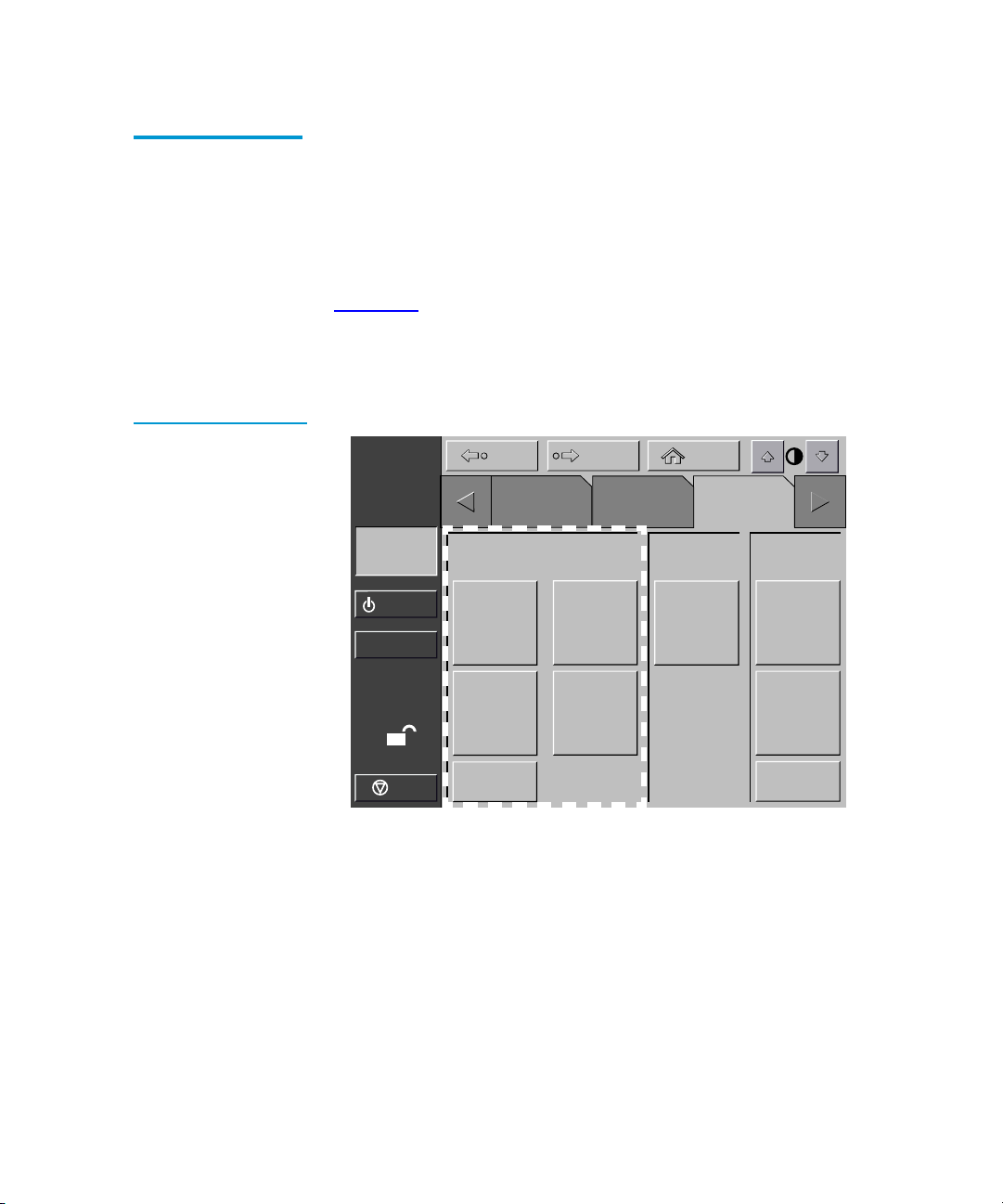
Chapter 4 Service Commands
Generating Reports
Generating Any Service Report
Figure 31 Service
Screen - Reports
Press the appropriate button in the Service screen.
4
Within a few seconds, the report is displayed on the screen.
Statistics Report
Figure 32
shows a sample Statistics report.
Press the Update button to update the report (otherwise the report
will update periodically).
About
Quantum|ATL
System
Off-line
Standby
Load Port
Back Forward
Tapes
Report
Statistics
SysTest
Library
Results
Operator
Home
Service
Test Misc.
SysTest
Library
Initialize
Nonvol
Statistics
4
Initialize
Nonvol
Config
Change
Password
S
Stop
Actuator
System
Monitor
Auto
Clean
Quantum|ATL P3000 Series User’s Guide 59
Page 80

Chapter 4 Service Commands
Generating Reports
Figure 32 Report:
Statistics Screen
Figure 33 Report:
Actuator Status
Screen
About
Quantum|ATL
System
Off-line
Standby
Load Port
S
Stop
Report: Statistics
Power On Time (Hr: Min: Sec): 360: 05: 56
Command Time (Hr: Min: Sec): 108: 08: 17
Pick Bin Count: 26501
Place Bin Count: 26435
Pick Drive Count: 11323
Place Drive Count: 10143
Pick Load Port Count: 873
Place Load Port Count: 877
Horizontal Move Count: 268831
Vertical Move Count: 152238
Actuator Report
Figure 33
About
Quantum|ATL
shows a sample Actuator Status report.
Back Forward
Tapes
Back Forward
Tapes
Operator
Operator
Home
Service
Update
4
Home
Service
System
Off-line
Standby
Load Port
S
Stop
Report: Actuator Status
Horizontal Position (in.): 8.752
Vertical Position (in.): 3.126
Extension Position (in.): 0.015
Gripper Position: Closed
Rotary Position: F ront
PTM Position: Inside
60 Quantum|ATL P3000 Series User’s Guide
Page 81

Chapter 4 Service Commands
Generating Reports
Figure 34 Report:
SysTest Library
Results Screen
SysTest Report
Figure 34
About
Quantum|ATL
System
Off-line
Standby
Load Port
shows a sample System Test report.
Back Forward
Report: SysTest Library Results
Pick and Place Total Count: 62466
System Test Status: B 80 0B
Total Test Time (Hr:Min:Sec): 61:42:35
Test Type: Random
Avg. Drive to Bin Move Time (Sec): 0.000
Avg. Bin to Drive Move Time (Sec): 0.000
Avg. Bin to Bin Move Time (Sec): 0.000
Longest Move Time (Sec): 0.000
S
Stop
Bad Barcode Reading Count: 0
Place to Drive Count: 2221
Place to Bin Count: 14202
Place to Load Port Count: 2
AutoClean Report
Tapes
Operator
4
Home
Service
4
Figure 35
shows a sample AutoClean report.
Quantum|ATL P3000 Series User’s Guide 61
Page 82

Chapter 4 Service Commands
Testing the Library
Figure 35 Report:
AutoClean Status
Screen
About
Quantum|ATL
System
Off-line
Standby
Load Port
S
Stop
When you have finished reviewing the report, press the Back
button to return to the Service screen.
Testing the Library
Back Forward
Tapes
Report: AutoClean Status
Auto Clean Enabled: FALSE
Auto-Clean State: Idle
Cleaning Operation Count: 0
Bad Operation Count: 0
Untracked Operation Count: 0
Last to Drive Error Status: 0 00 00
Last to Load Port Error Status: 0 00 00
Last to Home Error Status: 0 00 00
Operator
Home
Service
4
The Service screen provides a testing command:
• SysTest—this command tests library operation by swapping
tape cartridges between storage bins or drives.
Caution:
This screen is meant to be used only by qualified,
ATL-trained personnel. It is presented here for
explanation only. SysTest will alter inventory
information.
Performing a System Test
62 Quantum|ATL P3000 Series User’s Guide
To perform a system test:
4
From the Service screen, press the SysTest Library button.
1
Page 83

Chapter 4 Service Commands
Testing the Library
The Test: SysTest Library screen is displayed (see figure 36).
Figure 36 Test:
Systest Library Screen
About
Quantum|ATL
System
Off-line
Standby
Load Port
S
Stop
Select one of the following system test options:
2
Back Forward
Tapes
Test: Systest Library
Random
Swap
Bins
Swap
Drives
Use
Barcodes
Operator
Home
Service
# of Runs:
_
Continuous
Execute
1 2
3 4
5 6
7 8
9 0
• Swap Bins - test storage bins only
• Swap Drives - test drives only
Select all desired test options as follows:
3
• Random - swap cartridges at random
Select
• Use Barcodes - read barcode as cartridges are swapped
• Continuous - repeat test until aborted
Note:
The Continuous button must be de-selected to enter
“# of Runs”.
When you have selected the type of test and all test options,
4
press the Execute button.
A “Command In Progress” dialog box is displayed.
The system test continues until completed unless you press the
Abort button. If you pressed the Continuous button in step 3,
you must press the Abort button to stop the test.
Quantum|ATL P3000 Series User’s Guide 63
Page 84

Chapter 4 Service Commands
Initializing Non-Volatile Information
Initializing Non-Volatile Information
The Service screen contains two commands involving information
stored in nonvolatile memory:
Caution:
• Initialize nonvolatile memory configuration—returns the library
configuration to its factory-default condition, eliminating any
changes made using the Configure Library and Configure
Options commands in the Operator screen and invalidates the
calibration data.
• Initialize nonvolatile memory statistics—purges nonvolatile
memory of all statistical information about library operation.
This information is used to generate the statistical report
described on page 58
The following two commands are meant to be used
only by qualified, ATL-trained personnel. They are
presented here for explanation only. Serious
operational problems and data loss may occur if you
do not fully understand the consequences of these
commands.
.
4
Executing Either Command
To execute either command:
4
On the Service screen, press the button that corresponds to the
1
command you want to execute. The GUI displays a dialog box
prompting you to Continue or Cancel the command.
Press Continue. A “Command in Progress” dialog screen is
2
displayed.
Note:
If it becomes necessary to abort the command, press
Cancel.
64 Quantum|ATL P3000 Series User’s Guide
Page 85

Chapter 5
5
Multi-Unit Commands
This chapter describes the Multi-Unit screen commands of the
library Graphical User Interface (GUI). Topics covered are:
• Opening the multi-unit screen
• Configure multi-units (P2000/P3000)
• Calibrating the libraries in a multi-unit configuration
Note:
Caution:
Refer to the ATL Pass Through Mechanism Installation
Instructions, PN 6311615, for more information regarding
P2000/P3000 multi-unit configurations.
Multi-Unit Commands on the GUI are meant to be
used only by qualified, Quantum|ATL-trained
personnel. They are presented here strictly as
presentation only. Serious operational problems and
data loss may occur if you do not understand the
consequences of these commands.
Quantum|ATL P3000 Series User’s Guide 65
Page 86

Chapter 5 Multi-Unit Commands
Opening the Multi-Unit Screen
Opening the Multi-Unit Screen
To open the Multi-Unit screen:
Press the Multi-Unit tab.
1
The Multi-Unit screen is restricted to individuals
with Operator level access privileges.
For information about changing passwords, see
Executing Either Command
Back Forward
Operator
System
Off-line
Standby
Enter Password
Figure 37 Enter
Password Screen
Note:
The GUI displays a password screen (see figure 37
Enter the correct service password to gain access to the Multi-
2
Unit screen (see figure 38
The default multi-unit password is “1234.”
Note:
About
Quantum|ATL
5
).
).
on page 64.
Home
Service
Multi
Unit
1 2
3 4
Load Port
O
Stop
66 Quantum|ATL P3000 Series User’s Guide
Enter Password: _
5 6
7 8
9 0
Enter
Page 87

Chapter 5 Multi-Unit Commands
Configure Multi-Units (P2000/P3000)
Figure 38 Multi-Unit
Screen
Back Forward
Home
About
Quantum|ATL
System
Off-line
Standby
Load Port
O
Stop
Multi-Unit
Operator Service
Configure
Multi-Unit
Calibrate
All PTMs
Configure Multi-Units (P2000/P3000)
The Configure Multi-Unit command allows you to set the
following:
Multi
Unit
5
• Library Unit field—sets whether the library is single, slave, or
master in the multi-unit configuration
• Library Unit # field—sets the number assigned to a particular
library in the multi-unit configuration. Libraries are numbered
left to right beginning with 0 and ending with 4
• # of Libraries field—sets the total number of libraries in the
multi-unit configuration
• LUN Config field—this option will always be set to Single LUN
To configure a Multi-Unit Library option:
In the Multi-Unit screen, press the Configure Multi-Unit
1
button.
The GUI displays the Configure: Multi-Unit screen (see
figure 39
Quantum|ATL P3000 Series User’s Guide 67
).
Page 88

Chapter 5 Multi-Unit Commands
Calibrating the Libraries in a Multi-Unit Configuration
Figure 39 Configure
Multi-Unit
Back Forward
About
Quantum|ATL
System
Off-line
Standby
Load Port
O
Stop
Press the Select button to access the option to configure.
2
Using the arrow buttons, scroll through the available values for
3
Operator Service
Configure: Multi-Unit
Library Unit:
Library Unit #:
# of Libraries:
LUN Config: SINGLE LUN
SINGLE
Home
Multi
Unit
Select
Change
the selected option.
When the desired value is displayed, press the Select button to
4
advance to the next option.
When you have finished making changes to the multi-unit
5
configuration options, press the Change button to save the
options and complete the configuration.
Calibrating the Libraries in a Multi-Unit Configuration
The Calibrate All PTMs command enables you to calibrate all pass
through mechanisms in all of the libraries in the multi-unit
configuration. Calibrate the libraries during the initial installation
and after any maintenance procedure.
To calibrate all library elements:
From the Master library in the multi-unit configuration, press
1
the Multi-Unit tab.
68 Quantum|ATL P3000 Series User’s Guide
5
Page 89

Chapter 5 Multi-Unit Commands
Calibrating the Libraries in a Multi-Unit Configuration
The GUI displays the Multi-Unit screen (see figure 40).
Press the Calibrate All PTMs button.
2
The GUI displays a Command In Progress dialog box while the
calibration process is in progress.
Figure 40 Multi-Unit
Screen
Note:
About
Quantum|ATL
System
Off-line
Standby
Load Port
O
Stop
Multi-Unit calibration MUST be executed from the
master library designated during multi-unit
configuration.
Back Forward
Operator Service
Multi-Unit
Configure
Multi-Unit
Calibrate
All PTMs
Home
Multi
Unit
Quantum|ATL P3000 Series User’s Guide 69
Page 90

Chapter 5 Multi-Unit Commands
Calibrating the Libraries in a Multi-Unit Configuration
70 Quantum|ATL P3000 Series User’s Guide
Page 91

Chapter 6
6
Troubleshooting
This chapter describes problems you may encounter during the
setup and operation of the P3000. Corrective information is
provided to help you resolve the problems.
Several of these problems produce error messages on the graphical
user interface (GUI) called sense data values. Sense data value
messages consist of a number and a description of the error.
Common Problems and Solutions
The troubleshooting information in this section covers the
following topics:
• Start-up problems
•GUI problems
• Robotics problems
• Operating problems
• Tape drive problems
Quantum|ATL P3000 Series User’s Guide 71
6
Page 92

Chapter 6 Troubleshooting
Common Problems and Solutions
Start-up Problems
6
Table 7
describes corrective actions for problems which occur
during start-up.
Table 7 Start-up
Problems
Problem Corrective Action
The library does not power
on.
The library or tape drives do
not respond on the SCSI bus.
During initialization, the
library reports “Not Ready.”
One or more tape drives fail
to spin up during start-up.
The library starts up in
standby mode.
Make sure the power cord is connected to a dedicated,
grounded electrical outlet and the power switch behind the
slide panel just below the GUI is on.
Make sure each SCSI device on the same SCSI bus has a unique
address and the last device is properly terminated.
Determine the failure type by checking any previous error codes
returned to the host computer. Correct the cause of the error.
Check all SCSI cabling and termination behind the center back
access door. If necessary, contact your field service engineer
about replacing the drives.
Press the Standby button to verify that the library switches to
on-line mode. You can use the GUI to select either on-line or
standby mode at power up.
72 Quantum|ATL P3000 Series User’s Guide
Page 93

Chapter 6 Troubleshooting
Common Problems and Solutions
GUI Problems
Table 8 GUI
Problems
6
Table 8
describes corrective actions for GUI problems.
Problem Corrective Action
GUI is blank. Confirm that power is on, then contact an authorized field
service engineer.
The GUI does not respond to
Contact an authorized field service engineer.
touch.
An error message is
displayed.
Write down the details of the error message, including the SK,
ASC, and ASCQ numeric values.
Press Okay to clear the message.
Robotics Problems
Table 9 Robotics
Problems
Table 9
6
describes corrective actions for robotics problems.
Problem Corrective Action
The robot does not move at
power up.
Make sure that all internal packing materials and brackets have
been removed.
Check the Stop and Standby buttons; make sure the library is online and the Stop button is disabled.
The gripper partially grips
a tape cartridge.
The barcode reader on the
gripper fails.
Issue a Move Cartridge command to move the cartridge from the
gripper to an empty storage bin.
Verify that nothing obstructs the reader.
Then, restart the library. If the problem continues, contact a field
service engineer.
Quantum|ATL P3000 Series User’s Guide 73
Page 94

Chapter 6 Troubleshooting
Common Problems and Solutions
Problem Corrective Action
The robot times out or fails
during an operation.
Check that the tape cartridge involved in the operation is
properly positioned in the bin or drive and ready to be picked.
Check that the robot is not obstructed in any way.
Retry the operation. If it still fails, contact a field service engineer.
Misplaced cartridge. Open the doors.
Inspect the suspect tape cartridge for damage. Gently shake the
cartridge. If there are any sounds of loose pieces, do not put the
cartridge back in the library.
Retrieve the cartridge, orient it properly, and place the cartridge
in an empty storage bin. (Do not try to place the cartridge in the
gripper.)
Perform an inventory (see Performing an Inventory
If the operator manually places a cartridge in an empty bin, he
must then run an inventory so the library records the position of
the manually placed cartridge.
A cartridge is in the
gripper at start-up, when a
move command is
requested, or after a place
command is executed.
Open the front doors.
Manually remove the cartridge from the gripper and place it in
an empty bin.
Perform an inventory (see Performing an Inventory
on page 49).
on page 49).
If the operator manually places a cartridge in an empty bin, he
must then run an inventory so the library records the position of
the manually placed cartridge.
The gripper does not have
a cartridge after
completing a pick
command.
74 Quantum|ATL P3000 Series User’s Guide
Make sure a cartridge can be found in the source location.
Retry the command. If the pick operation fails again, contact a
field service engineer.
Page 95

Chapter 6 Troubleshooting
Common Problems and Solutions
Operating Problems
Table 10 Problems
During Library
Operation
Table 10
6
during library operation.
describes the corrective action for problems which occur
Problem Corrective Action
The host computer
cannot communicate
with the library.
This may be a SCSI bus time-out or a premature disconnect problem.
Check cable connections, cable length, SCSI addresses, and termination.
Restart the host and the library.
If the host and library still are not communicating, contact a field
service engineer.
A cable or
terminator is
disconnected from
Reconnect the cable or terminator according to the guidelines found in
the cabling section in Connecting Host Workstations
guide.
the SCSI bulkhead.
A tape cartridge
(tape medium) is
reported not present.
This indicates that the gripper could not sense a tape cartridge in a
particular storage bin even though the inventory reports that it is
present.
on page 21 of this
A move command
failed.
A flash memory
error is reported.
Check to see if the designated cartridge is present. If it is, make sure it is
properly seated. (For a tape drive, make sure the cartridge is completely
unloaded.) Then retry the command.
If the error persists, contact a field service engineer.
Check the source and destination bins. The source bin should hold the
cartridge to be moved; the destination bin should be empty.
Make sure the gripper is empty and all actuators are free of obstruction.
Also, make sure the library is on-line and the Stop button is released.
Retry the command.
Contact a field service engineer.
Quantum|ATL P3000 Series User’s Guide 75
Page 96

Chapter 6 Troubleshooting
Common Problems and Solutions
Problem Corrective Action
A maximum
temperature
exceeded warning is
displayed.
Tape Drive Problems
Table 11 Tape Drive
Problems
Problem Corrective Action
The library is
unable to
communicate
with a drive.
The tape drive
does not eject a
cartridge.
Turn off the library and allow it to cool down. Lower the room
temperature, if possible, and increase ventilation around the library.
(If the operating temperature is too high, the library will automatically
shut down until the temperature drops.)
Table 11
6
drives.
This is indicated by a Drive Communication Time-out error. Contact a
field service engineer.
Reset the library and retry the unload command.
If the tape still does not unload, stop the library, open the front door, and
manually unload and eject the cartridge (see Manually Ejecting a Tape
Cartridge on page 40).
describes the corrective action for problems with the tape
A drive handle
error occurs.
Tape Drive LED Conditions
Contact an ATL field service engineer.
These actions are to be performed based on the LED displays on
6
the backs of the drive canisters in mixed media P3000 tape
libraries. Table 12
and figure 41 show the diagnostic table of tape
drive conditions as indicated by the two LEDs at the back of the
tape drive canister.
76 Quantum|ATL P3000 Series User’s Guide
Page 97

Chapter 6 Troubleshooting
Common Problems and Solutions
Table 12 Tape Drive
LED Conditions (SDLT
and LTO drives)
Green
Red LED
LED Condition Action
ON ON Reserved Contact an ATL Field Service
Engineer
ON Flashing Reserved Contact an ATL Field Service
Engineer
ON OFF Drive power fail (detected by
firmware
Toggle the drive canister screw
cover switch to clear the drive
power fail condition. If the LED
reappears, contact an ATL Field
Service Engineer
OFF ON Good No action
OFF Flashing SCSI bus incompatible
(detected by firmware)
Indicates LVD/HVD
incompatibility. Ensure that the
SCSI cable and host bus adapter are
correct and replace if necessary.
OFF OFF No power to tape drive
interface board
Ensure that:
• Be sure that the library power is
ON.
• Drive canister screw cover switch
is in the position so that it covers
the screw.
• Check library configuration on
the GUI to see if the library is
configured with the correct
number of drives.
• If the condition persists, call an
ATL Field Service Engineer.
Quantum|ATL P3000 Series User’s Guide 77
Page 98

Chapter 6 Troubleshooting
Common Problems and Solutions
Green
Red LED
LED Condition Action
Flashing ON Drive unhealthy (detected by
firmware). Detects hardware
errors in DLT and SDLT drives.
It also detects the absence of a
tape cartridge; and in DLT and
SDLT drives, the drive is not
ready to accept a new cartridge.
In LTO drives, this condition is
a warning of a snapped tape.
Flashing Flashing Drive inserted (under hardware
control, upon the first firmware
command, the LEDs will turn
off and obey the firmware
command.
Flashing OFF Microbridge incompatibility
(under hardware control).
Figure 41 Tape Drive
LEDs
Contact an ATL Field Service
Engineer
This condition should terminate
shortly after the library is turned
ON. If the condition persists, call an
ATL Field Service Engineer.
Contact an ATL Field Service
Engineer
Red LED
Drive canister screw
cover switch
78 Quantum|ATL P3000 Series User’s Guide
Green LED
Drive canister screw
Page 99

Appendix A
A
Library Specifications
This appendix lists characteristics and specifications of the P3000.
These characteristics and specifications are categorized as follows:
• Physical characteristics
• Performance characteristics
• Environmental specifications
Note:
For tape drive specifications see the appropriate tape
drive product manual.
Physical Characteristics
Table 13 provides dimensions and other physical characteristics of
the library unit.
Quantum|ATL P3000 Series User’s Guide 79
1
Page 100

Appendix A Library Specifications
Physical Characteristics
Table 13 Physical
Characteristics
Table 14 Interfaces
Unit Dimensions and Weight
Width 57 in. (144 cm)
Depth 29 in. (74 cm)
Footprint 11.50 sq. feet (1.07 sq. meters)
Height 75 in. (191 cm)
Weight Library: 1300 lbs (591 Kg)
DLT Drives: 13.5 lbs. (6.12 kg) each
DLT Cartridges: 7.7 oz. (218 kg) each
Tape Drives and Cartridges
Tape Drives, Max. No. Up to 16 tape drives
Cartridges, Max. No. 0-326 tapes
Host to Library Interfaces
Software SCSI-2 medium changer command set
Power Input
Power cord 1 or 2 standard US, IEC 320 C19 male
connector rated at 125VAC (NEMA 5-20 P
connector included)
Host to Tape Drive Interface
Software SCSI-2
Library Diagnostics
Diagnostics RS-232C service port for connection to a field
service PC or Solaris Workstation running
diagnostic software.
80 Quantum|ATL P3000 Series User’s Guide
 Loading...