

Page 1

Quantum|ATL 7100 Series
Facilities Planning and
Inst allation Guide
6241101-02
Ver. 2 Rel. 2
Page 2

Quantum|ATL 7100 Series Facilities Planning and Installation Guide, 6241101-02, Ver. 2 Rel. 2, August
2001. Printed in the USA.
Quantum|ATL Products, Inc. provides this publication “as is” without warranty of any kind, either express
or implied, including but not limited to the implied warranties of merchantability or fitness for a particular
purpose. Quantum|ATL Products, Inc. may revise this publication from time to time without notice.
COPYRIGHT STATEMENT
Copyright 2001 by ATL Products, Inc. All rights reserved.
Your right to copy this manual is limited by copyright law. Making copies or adaptations without prior
written authorizati on of ATL Produ cts, Inc. is proh ibited by law an d constitu tes a punis hable v iolati on of the
law.
TRADEMARK STATEMENT
Prism Library Architect ur e, I nte lli Grip, Web A dm in, and We bLi br ari an ar e all t ra dema rks o f Quant u m|A TL
Products, Inc.
Other trademarks may be mentioned herein which belong to other companies.
6207947-06cP 34
Page 3
Contents
Preface xi
Chapter 1 Library Specifications and Site Requir ements 1
Library Description................................................................................1
Supported Tape Drives and Cartridges........................................3
Bin and Tape Drive Numbering Conventions.............................3
Library Specifications ............................................................................6
Site Requirements...................................................................................7
Floor Space................................................................................. .......7
Floor Leveling...................................................................................8
Floor Loading ...................................................................................8
Floor Clearance........................................................ ......... ......... .......8
Power.................................................................................................8
Grounding.........................................................................................9
Chapter 2 Unpacking and Moving the Library 11
Receiving the Library.................................................... ......... ......... .....11
Unpacking the Library.........................................................................13
Rolling the Library off of the Pallet ...................................................16
Quantum|ATL 7100 Series Facilities Planning and Installation Guide iii
Page 4

Contents
Moving the Library to the Final Installation Area...........................17
Removing the Protective Packaging Material..................................18
Storing the Packaging Material ....................................................20
Packaging the Library for Reshipment..............................................21
Chapter 3 Installing the Library 23
Required Tools......................................................................................23
Leveling the Library.............................................................................24
Operational Setup and Checkout.......................................................26
Applying Power to the Library....................................................26
Setting SCSI Addresses and Running the Library Self-Test...........28
Connecting the Library to the Host Controller................................28
Preparing the Library for Operation..................................................32
$SSHQGL[$ 6&6,&DEOLQJ2SWLRQV
SCSI Ports...............................................................................................34
Single-Wire Configuration..................................................................35
Two-Wire SCSI Configuration (Default)...........................................37
Four-Wire SCSI Configuration...........................................................3 9
$SSHQGL[% 5HJXODWRU\6WDWHPHQWV
FCC Statement ................................................................... ......... ..........41
Industry Canada (Digital Apparatus) ...............................................42
CISPR-22 WARNING!...................................................................42
ACHTUNG! ....................................................................................42
ATTENTION! .................................................................................42
Notice for USA and Canada Only......................................................43
Laser Statement.....................................................................................44
Class 1 Laser Product ....................................................................44
Laser Klasse 1..................................................................................44
Appareil à Laser de Classe 1 ........................................................44
Producto Láser de Clase 1.............................................................44
Luokan 1 Laserlaite........................................................................4 5
iv Quantum|ATL 7100 Series Facilities Planning and Installation Guide
Page 5

Contents
Battery Statement .................................................................................45
CAUTION.......................................................................................45
LET OP.............................................................................................45
VAROITUS......................................................................................45
ATTENTION ..................................................................................46
ACHTUNG.....................................................................................46
Attenzione.......................................................................................46
PRECAUCIÓN...............................................................................46
VARNING!......................................................................................46
Glossary 47
Index 51
Quantum|ATL 7100 Series Facilities Planning and Installation Guide v
Page 6

Contents
vi Quantum|ATL 7100 Series Facilities Planning and Installation Guide
Page 7
Figures
Figure 1 Left Panel Removed............................................................2
Figure 2 Library Numbering Conventions (100 cartridges..........4
Figure 3 Library Numbering Conventions (68 Cartridges) .........5
Figure 4 Library AC Power Receptacle...........................................9
Figure 5 Library Unloading Space Requirements .......................12
Figure 6 Removing the Box from the Pallet..................................14
Figure 7 Unpacking the Library.....................................................15
Figure 8 Extension Axis Tie-Wraps ...............................................19
Figure 9 Packing Block Locations ..................................................20
Figure 10 Power Receptacle and Power Switch Location ............27
Figure 11 Connecting the SCSI Cables (two-wire, four drives)...31
Figure 12 SCSI Cabling Block Diagram (2 drives, 1 wire)............36
Figure 13 SCSI Cabling Block Diagram (4 drives, 2 wires) ..........38
Figure 14 SCSI Cabling Block Diagram (7 drives, 4 wires) ..........40
Quantum|ATL 7100 Series Facilities Planning and Installation Guide vii
Page 8

Figures
viii Quantum|ATL 7100 Series Facilities Planning and Installation Guide
Page 9

Tables
Table 1 Library Mechanical Specification.....................................6
Table 2 Library Power Specification..............................................6
Table 3 Library Environmental Specification...............................6
Table 4 Library Floor Space Requirements...................................8
Table 5 7100 Series SCSI Cabling Configuration........................29
Table 6 Library SCSI Addresses (default)...................................34
Quantum|ATL 7100 Series Facilities Planning and Installation Guide ix
Page 10

Tables
x Quantum|ATL 7100 Series Facilities Planning and Installation Guide
Page 11
Preface
Audience
Purpose
'RFXPHQW
2UJDQL]DWLRQ
This document was written for Field Service Engineers (FSEs) of
the Quantum|ATL 7100 Series library (library) . It describes f acility
preparation and provides the procedures for first-time installation
of the library.
This document provides the following information:
• Library specifications
• Site requirements
• Unpacking and moving instructions
• Installing the library
Following is a brief description of chapter contents.
• Chapter 1, “
provides the specifications of the library and discusses site
flooring, environmental and electrical requirements.
Library Specifications and Site Requirements,”,
4XDQWXP_$7/6HULHV)DFLOLWLHV3ODQQLQJDQG,QVWDOODWLRQ*XLGH [L
Page 12

3UHIDFH
• Chapter 2, “Unpacking and Moving the Library,”, describes
how to unpack and move the library to its final installation
area.
1RWDWLRQDO
&RQYHQWLRQV
• Chapter 3, “
Installing the Library,”, lists the to ols required and
provides the procedures necessary for insta lling and testing the
library prior to operation.
• Appendix A, “
SCSI Cabling Options,” lists the SCSI cabling
options for the library
This manual uses the following conventions:
Caution: Cautions indicate potential hazards to equipment
and are included to prevent damage to equipment.
Note: Notes emphasize important information related to the
main topic.
Warning: Warnings indicate potential hazards to personal
safety and are included to prevent injury.
This manual uses the following:
• Right side of the library — Refers to the right side as you face
the component being described.
• Left side of the library — Refers to the left side as you face the
component being described.
• b — All binary numbers are succeeded by “b.”
• h — All hexadecimal numbers are succeeded by “h.”
• Error or attention conditions are represented in parenthesis
that translate as follows:
(SK=S ASC=AA ASCQ=QQ)
where:
[LL 4XDQWXP_$7/6HULHV)DFLOLWLHV3ODQQLQJDQG,QVWDOODWLRQ*XLGH
Page 13

S — hexadecimal sense key value
AA — hexadecimal additional sense code
QQ — hexadecimal additional sense code qualifier
3UHIDFH
5HODWHG
'RFXPHQWV
Document
Number Title Description
6241102 Quantum|ATL 7100
Series Tape Library
Operator’s Guide
6241104 Quantum|ATL 7100
Series Library Diagnostic
Software User’s Manual
6241105 Quantum|ATL 7100
Series Library Software
Interface Guide
Documents related to the library are shown below:
Describes the operator-accessible components of
the library and provides both operating and
troubleshooting procedures.
Provides procedures for installing and using the
Quantum|ATL 7100 Series Diagnostic Software.
For software engineers and programmers
developing applications to control the
Quantum|ATL 7100 Series library.
SCSI-2 Specification 0
The SCSI-2 communications specification is the proposed
American National Standard for information systems, dated
March 9, 1990. Copies may be obtained from:
Global Engineering Documents
15 Inverness Way, East
Englewood, CO 80112
(800) 854-7179 or (303) 397-2740
4XDQWXP_$7/6HULHV)DFLOLWLHV3ODQQLQJDQG,QVWDOODWLRQ*XLGH [LLL
Page 14

3UHIDFH
Contacts
Quantum|ATL company contacts are listed below.
Quantum|ATL Corporate Headquarters 0
To order documentation on the library or on other products
contact:
Quantum|ATL
P.O. Box 57100
Irvine, CA 92619-7100
(949) 856-7800
(800) 284-5101
Technical Publications 0
To comment on existing documentation send e-mail to:
atl-docs@atlp.com
Visit the Quantum|ATL home page at:
http://www.atlp.com
0
Customer Support
The Quantum|ATL Customer Support Department provides a
24-hour help desk that can be reached at:
North/South America: (949) 725-2100 or
(800) 284-5101
Asia/Pacific Rim: (Internat ional Code)
+61 7 3862 4834
Europe/Middle East/Africa: (International Code)
+44 (0) 1256 848748
[LY 4XDQWXP_$7/6HULHV)DFLOLWLHV3ODQQLQJDQG,QVWDOODWLRQ*XLGH
0
Page 15

Send faxes for the Customer Support Department to:
North/South America: (949) 725-2176
Asia/Pacific Rim: (International Code )
+61 7 3862 4677
Europe/Middle East/Africa: (International Code)
+44 (0) 1256 848777
Send e-mail for the Customer Support Department to:
3UHIDFH
North/South America:
helpdesk@atlp.com
Asia/Pacific Rim: ATL-helpdesk-apac@atlp.com
Europe/Middle East/Africa: ukhelpdesk@atlp.com
4XDQWXP_$7/6HULHV)DFLOLWLHV3ODQQLQJDQG,QVWDOODWLRQ*XLGH [Y
Page 16

3UHIDFH
[YL 4XDQWXP_$7/6HULHV)DFLOLWLHV3ODQQLQJDQG,QVWDOODWLRQ*XLGH
Page 17
Chapter 1
1Library Specifications and
Site Requirements
This section provides the library physical specifications and
addresses the floor and electrical requirements of the site.
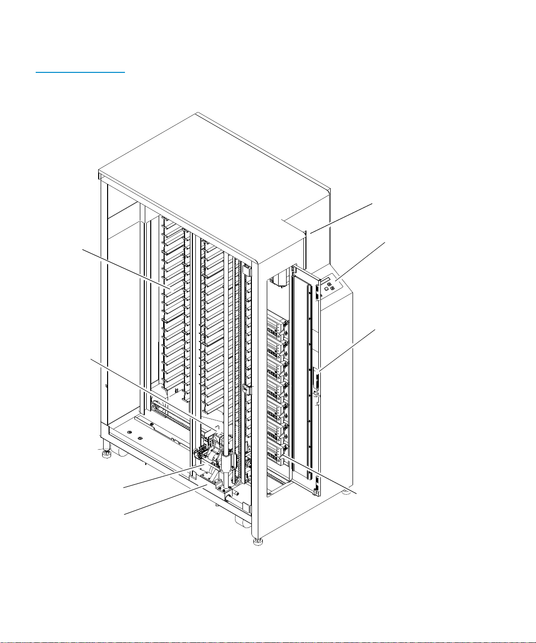
Library Description 1
The Quantum|ATL 7100 Series library (library) is the automated
storage and retrieval component of an automated tape library
system (see figure 1
capable of storing a maximum of 96 tape cartridges in a Fixed
Storage Array (FSA). An operator-accessible load port at the front
of the library can hold an additional four tape cartridges for a
maximum total of 100.
Quantum|ATL 7100 Series Facilities Planning and Installation Guide 1
). It contains up to seven tape drives and is
Page 18
Chapter 1 Library Specifications and Site Requirements
Library Description
Figure 1 Left Panel
Removed
Fixed Storage
Array (FSA)
(96 bins)
Load port (open)
(4 additional cartridges)
Control panel
Gripping
mechanism
Vertical carriage
Horizontal carriage
(Left-side cosmetic panel removed)
(Front)
Door handle
(door shown open)
Tape drives (7)
2 Quantum|ATL 7100 Series Facilities Planning and Installation Guide
Page 19

Chapter 1 Library Specifications and Site Requirements
Library Descriptio n
A host computer communicates with the library through a SCSI
interface using the SCSI-2 medium changer command set. In a
typical operation, the host commands the robotics to transfer tape
cartridges between storage bins (in the FSA), tape drives or the
load port. Each time a tape cartridge is transferred, a gripping
mechanism is moved to the tape cartridge location where it
“picks” the tape cartridge, moves it to the designated (new)
location and then “places” it.
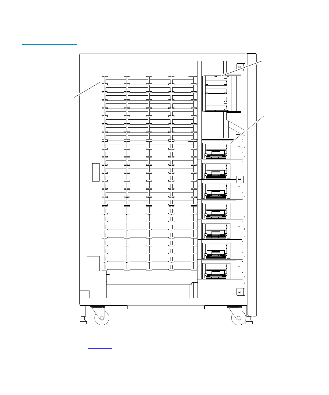
Supported Tape Drives and Cartridges
Bin and T ape Drive Numbering Conventions
The library is capable of supporting up to seven tape drives.
1
Figure 2 shows the numbering conventions for the 100 cartridge
library's
1
• FSA bins
• Load port bins
• Tape drives.
This num bering convention is used in the diagnostic soft ware and
the library menu mode, which is viewed in the status display area
of the control panel.
Quantum|ATL 7100 Series Facilities Planning and Installation Guide 3
Page 20
Chapter 1 Library Specifications and Site Requirements
Library Description
Figure 2 Library
Numbering
Conventions (100
cartridges
Fixed Storage
Array (FSA)
bins
Bin 0
Bin 1
Bin 2
Bin 3
Bin 4
Bin 5
Bin 6
Bin 7
Bin 8
Bin 9
Bin 10
Bin 11
Bin 12
Bin 13
Bin 14
Bin 15
Bin 16
Bin 17
Bin 18
Bin 19
Bin 20
Bin 21
Bin 22
Bin 23
Bin 24
Bin 25
Bin 26
Bin 27
Bin 28
Bin 29
Bin 30
Bin 31
Bin 32
Bin 33
Bin 34
Bin 35
Bin 36
Bin 37
Bin 38
Bin 39
Bin 40
Bin 41
Bin 42
Bin 43
Bin 44
Bin 45
Bin 46
Bin 47
Bin 48
Bin 49
Bin 50
Bin 51
Bin 52
Bin 53
Bin 54
Bin 55
Bin 56
Bin 57
Bin 58
Bin 59
Bin 60
Bin 61
Bin 62
Bin 63
Bin 64
Bin 65
Bin 66
Bin 67
Bin 68
Bin 69
Bin 70
Bin 71
Bin 72
Bin 73
Bin 74
Bin 75
Bin 76
Bin 77
Bin 78
Bin 79
Bin 80
Bin 81
Bin 82
Bin 83
Bin 84
Bin 85
Bin 86
Bin 87
Bin 88
Bin 89
Bin 90
Bin 91
Bin 92
Bin 93
Bin 94
Bin 95
Bin 0
Bin 1
Bin 2
Bin 3
Drive 0
Drive 1
Drive 2
Drive 3
Drive 4
Drive 5
Drive 6
Load port
bins
Tape
drives
Figure 3 shows the numbering convention for the 68 cartridge
library’s Fixed Storage Array bins, load port bins, and tape drives.
4 Quantum|ATL 7100 Series Facilities Planning and Installation Guide
Page 21
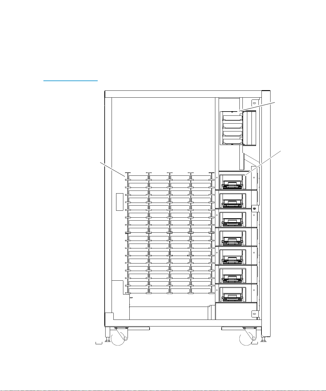
Figure 3 Library
Numbering
Conventions (68
Cartridges)
Fixed Storage
Array(FSA)
bins
Chapter 1 Library Specifications and Site Requirements
Library Descriptio n
This num bering convention is used in the diagnostic soft ware and
the library menu mode, which is viewed in the status display area
of the control panel.
Load port
bins
Bin 0
Bin 1
Bin 2
Bin 3
T ape drives
Bin 0
Bin 1
Bin 2
Bin 3
Bin 4
Bin 5
Bin 6
Bin 7
Bin 8
Bin 9
Bin 10
Bin 11
Bin 12
Bin 13
Bin 14
Bin 15
Bin 16
Bin 17
Bin 18
Bin 19
Bin 20
Bin 21
Bin 22
Bin 23
Bin 24
Bin 25
Bin 26
Bin 27
Bin 28
Bin 29
Bin 30
Bin 31
Bin 32
Bin 33
Bin 34
Bin 35
Bin 36
Bin 37
Bin 38
Bin 39
Bin 40
Bin 41
Bin 42
Bin 43
Bin 44
Bin 45
Bin 46
Bin 47
Bin 48
Bin 49
Bin 50
Bin 51
Bin 52
Bin 53
Bin 54
Bin 55
Bin 56
Bin 57
Bin 58
Bin 59
Bin 60
Bin 61
Bin 62
Bin 63
Drive 0
Drive 1
Drive 2
Drive 3
Drive 4
Drive 5
Drive 6
Quantum|ATL 7100 Series Facilities Planning and Installation Guide 5
Page 22

Chapter 1 Library Specifications and Site Requirements
Library Specificatio ns
Library Specifications 1
The following tables provide the specifications of the library.
Table 1 Library
Mechanical
Specification
Table 2 Library
Power Specification
Table 3 Library
Environmental
Specification
height 56.5 inches (143.5 cm)
width 23.5 inches (59.7 cm)
depth 36.5 inches (92.7 cm)
weight 550 lb. (250 kg) with 96 tape cartridges and 7 tape drives
installed
AC power rating 100-120V/200-240V, 7A/3.5A, 50/60 Hz
AC voltage range 90-132 VAC or 180-264 VAC
frequency range 47-63 Hz
temperature
storage — short-term (< 60 days)
storage — long-term (>60 days)
transport
operating
-40 to 151
41 to 122
-40 to 151
50 to 90
°
F (-40 to 66°C)
°
F (5 to 50°C)
°
F (-40 to 66°C)
°
F (10 to 32°C)
6 Quantum|ATL 7100 Series Facilities Planning and Installation Guide
Page 23

Chapter 1 Library Specifications and Site Requirements
Site Requirements
relative humidity
non-operating (storage)
non-operating (transport)
operating
altitude
short-term (<60 days storage)
operating
95% (Max. Wet Bulb Temp: 90
°
32
C)
95% (Max. Wet Bulb Temp:
°
115
F/46°C)
10-90% (Max. Wet Bulb Temp:
°
82
F/28°C)
42,000 ft. (12.8 km)
13,200 ft. (4.0 km, 471 mmHg) @
°
76
F/24.4°C Max.
°
F/
Site Requirements 1
Floor Space 1
The following paragraphs provide the floor space, leveling, floor
type, and loading requirements for the floor of the installation site.
Table 4
shows the floor space required by the library, including the
off-load and maintenance access areas.
Quantum|ATL 7100 Series Facilities Planning and Installation Guide 7
Page 24

Chapter 1 Library Specifications and Site Requirements
Site Requirements
Table 4 Library Floor
Space Requirements
(For maintenance only)
25”
36.5”
Ventilation and
cabling
157.5”
96”25”
74”
(Maintenance area)
Floor Leveling 1
Floor Loading 1
Floor Clearance 1
Power 1
24”
25”
Library
(For maintenance only)
(Ramp side/off-load area)
Front of library
The floor must be level to within 1/4” over a 6' x 6' area.
A standard raised computer floor rated a t 250 lb./f t
2
is sufficient to
support a fully loaded library.
The cabinet has a nominal floor clearance of 0.75" (1.9cm).
The library’s auto-ranging motor and logic power supplies will
accept single phase, 90-264VAC input power at 47-63 Hz.
8 Quantum|ATL 7100 Series Facilities Planning and Installation Guide
Page 25

Chapter 1 Library Specifications and Site Requirements
Site Requirements
The power inlet connector is a IEC-3 20 connector. For internati onal
applications you must replace the power cord set with a
harmonized 3x2.0mm
2
power cord set that is approved by the
country where used.
Figure 4 Library AC
Power Receptacle
Grounding 1
~100-120V / ~200 - 240V
3.5A / 7A 50/60 Hz
IEC-320 Type
Ground
Line
Neutral
The installation site must provide an earth ground cable for the
library.
Quantum|ATL 7100 Series Facilities Planning and Installation Guide 9
Page 26

Chapter 1 Library Specifications and Site Requirements
Site Requirements
10 Quantum|ATL 7100 Series Facilities Planning and Installation Guide
Page 27

Chapter 2
2Unpacking and Moving the
Library
This chapter describes how to unpack and move the library to the
final inst allation area.
Caution: The procedures in this chapter must be performed in
the order in which they appear in this chapter.
Receiving the Library 2
When you receive the crated library, unload it as close to the final
installation area as possible and allow approximately ten feet in
front of the off-load side of the pallet. This ensures that there is
enough space to lower the ramp before removing the library from
the pallet.
Also make sure that the room has a minimum ceiling height of
eight feet to provide clearance for removal of the box from the
pallet.
Quantum|ATL 7100 Series Facilities Planning and Installation Guide 11
Page 28

Chapter 2 Unpacking and Moving the Library
Receiving the Library
Inspect the crating material for any damage that may have
occurred during shipment. Report any damage found to the
shipper immediately.
Figure 5 Library
Unloading Space
Requirements
Pallet ramp
Library
Pallet
Unloading area
(minimum)
"
24"
36.5
40
"
10’
12 Quantum|ATL 7100 Series Facilities Planning and Installation Guide
Page 29

Chapter 2 Unpacking and Moving the Library
Unpacking the Library
Unpacking the Library 2
To unpack the library:
1 Cut the two steel bands that secure the library and packing
material to the pallet (see figure 6
Warning: Use care when cutting the steel bands that secure
the library to the pallet. These bands are under
tension and will snap away when cut.
2 Lift the cardboard box top cover straight up and off the pallet.
3 From the rear side of the container, pull the four cardboard box
retaining clips to their open position, and unwrap the
cardboard box from the library (see figure 6
).
).
Quantum|ATL 7100 Series Facilities Planning and Installation Guide 13
Page 30

Chapter 2 Unpacking and Moving the Library
Unpacking the Library
Figure 6 Removing
the Box from the Pallet
Steel bands
Top cover
R
A
M
P
S
I
D
E
(Front/off-load side)
Foam cap and
accessories tray
Pallet
Retaining
Cardboard box
clip (x4)
4 Remove the accessories tray from the top of the foam cap.
5 Remove the accessories tray from the top of the foam cap.
6 Remove the stop block (located underneath the library in front
of the casters).
7 Slide out the two pallet ramp sections located underneath the
library. Secure them to the pallet using the Velcro straps (see
figure 7
14 Quantum|ATL 7100 Series Facilities Planning and Installation Guide
).
Page 31

Figure 7 Unpacking
the Library
Chapter 2 Unpacking and Moving the Library
Unpacking the Library
8 Cut the shipping bag vertically along the heat-seal seam (see
figure 7
).
Accessories tray
Shipping bag
Stop block
Pallet ramp
Heat-seal seam
Quantum|ATL 7100 Series Facilities Planning and Installation Guide 15
Page 32

Chapter 2 Unpacking and Moving the Library
Rolling the Library off of the Pallet
9 Inspect the library for damage that may have occurred during
shipping.
Rolling the Library off of the Pallet 2
To remove the library from the pallet, use the procedure below and
refer to figure 6
Warning: The library weighs approximately 500 lb. It is
1 Verify that all leveling feet (located on the underside of the
library at the four corners) are in the up position. If not, rotate
each of the four feet clockwise until they are fully retracted.
.
recommended that two people perform the following
procedure.
2 With one person guiding the library at the off-load side of the
pallet, gently push the library down the ramp and onto the
floor.
3 Carefully fold and save the shipping bag. The bag is required if
you need to package the library for reshipment.
16 Quantum|ATL 7100 Series Facilities Planning and Installation Guide
Page 33

Chapter 2 Unpacking and Moving the Library
Moving the Library to the Final Installation Area
Moving the Library to the Final Installation Area 2
Warning: The library weighs approximately 500 lb. Use two
people to move the library.
Note: When moving the cabinet, one person should guide the
library from the rear while the other person pushes from
the front. Do not push the library up or down a ramp
with an incline greater than 10°.
Caution: The library has a nominal floor clearance of 0.75"
(1.9cm). Place stiff plastic or rubber mats on top of
carpeting that depresses more than the nominal
clearance and over floor cracks and door jambs prior
to rolling the library over them.
Caution: Any si de of the library can be used to push the li brary
to the final installation area. However, it is preferred
to push from the front of the library. When pushing
from the front, DO NOT push on the following nonstructural portions:
• Load port door
• Control panel
• Front door
• Front door handle
To move the library to the final installation area:
1 Based on the information above, prepare the path to the final
installation area.
2 Verify that all leveling feet are ful ly retracted. If the f eet are not
fully retracted, rotate each of the four feet counterclockwise
until they are fully retracted.
3 Roll the library to the final installation area.
Quantum|ATL 7100 Series Facilities Planning and Installation Guide 17
Page 34

Chapter 2 Unpacking and Moving the Library
Removing the Protective Packaging Material
Removing the Protective Packagin g Ma ter ia l 2
Refer to the figure 9
1 Locate the library door keys in the accessory kit and open the
throughout this procedure.
storage array door.
2 Remove the block securing the gripper.
3 Without cutting it, remove the tie-wrap securing the extension
axis platform to the horizontal axis carriage (see figure 8)
. The
tie-wrap is reusable.
4 Gently lift the extension axis up and pull the vertical axis block
out and away from the library.
5 Without cutting, remove the tie-wraps securing the horizontal
carriage assembly to the frame. The tie-wraps are reusable.
6 Gently push the carriage assembly forward.
7 Remove both the top and bottom horizontal axis blocks.
8 Slowly lower the extension axis to the bottom (resting)
position.
9 Close the storage array door.
18 Quantum|ATL 7100 Series Facilities Planning and Installation Guide
Page 35

Figure 8 Extension
Axis Tie-Wraps
Chapter 2 Unpacking and Moving the Library
Removing the Protective Packaging Material
Tie-wrap securing
extension axis
Quantum|ATL 7100 Series Facilities Planning and Installation Guide 19
Page 36

Chapter 2 Unpacking and Moving the Library
Removing the Protective Packaging Material
Figure 9 Packing
Block Locations
Top
horizontal
block
Gripper block
Bottom
horizontal
block
Vertical axis
block
Storing the Packaging Material
To store packaging material:
1 Slide the two pallet ramp sections into their shipping position
2
in the pallet.
2 Collapse the cardboard box.
3 Store the box, molded top, pallet and all other packing materia l
for possible later use.
20 Quantum|ATL 7100 Series Facilities Planning and Installation Guide
Page 37

Chapter 2 Unpacking and Moving the Library
Packaging the Library for Reship me nt
Packaging the Library for Reshipm ent 2
If it becomes necessary to crate the library for shipment, use the
procedure below and refer to the figures in this chapter.
Note: This procedure assumes that all cartridges have been
removed, power is off and cables are disconnected.
Caution: Observe proper ESD protective measures to prevent
damage to the library.
1 Open the storage array door.
2 Gently lift the extension axis up and place the vertical axis
block in position (see figure 9)
the bottom position.
, then lower the extension axis to
3 Install both the top and bottom horizontal axis blocks.
4 Gently slide the robotic mechanism towards the rear of the
library so that is up against the horizontal axis packing blocks.
5 Install the tie-wraps securing the extension axis for shipment
(see figure 8)
6 Close the storage array door.
7 Raise the leveling feet by rotating each foot counterclockwise
.
(as viewed from above) until they are fully retracted.
8 Move the library to the crating area observing all guidelines
described in Moving the Library to the Final Installation Are
a
on page 17.
9 Slide out the two pallet ramp sections (located underneath the
library) and secure them to the pallet using the Velcro straps
(see figure 7
10 Unfold the shipping bag and align the white tape to the pallet
on page 15).
bottom with respect to where the library casters will roll onto
the pallet.
Quantum|ATL 7100 Series Facilities Planning and Installation Guide 21
Page 38

Chapter 2 Unpacking and Moving the Library
Packaging the Library for Reshipment
11 Roll the library onto the pallet and into the shipping bag.
12 Seal the shipping bag by folding the seam over and taping the
edge.
13 Install the stop block in front of library front casters (see figure
7 on page 15).
14 Install the foam cap on the library and install accessory tray.
15 Wrap the box around the library and pallet and install the four
plastic re taining clips (refer to figure 6
Caution: It is recommended that the steel bands be
16 Install steel banding to secure the library and packing material
to the pallet.
on page 14).
tightened to approximately 200 lb. of tension
prior to shipment.
22 Quantum|ATL 7100 Series Facilities Planning and Installation Guide
Page 39

Chapter 3
3Installing the Library
This chapter describes the procedures necessary to install the
library.
Note: The customer’s System Administrator should be present
during these procedures.
Caution: The procedures in this chapter must be performed in
the order in which they appear in this chapter.
Required Tools 3
Use the following tools to install the library:
• #2 Phillips s crewdrive r
• Wire cutters
• Carpenter’s level
3
•
⁄4 inch open-ended wrench
Quantum|ATL 7100 Series Facilities Planning and Installation Guide 23
Page 40

Chapter 3 Installing the Library
Leveling the Library
• Digital voltmeter (DVM)
• ESD protection kit
Leveling the Library 3
To level the library:
Note: Completing this task involves leveling one side of the
library at a time, moving in a clockwis e direction sta rting
at the front and ending with the right-side of the library.
1 Move th e library onto its designated footprint in the final
installation area.
2 Lower each foot of the library until it makes contact with the
floor.
Caution: When adjusting the feet for leveling purposes,
DO NOT raise any foot so high that excess weight
is transferred to any single caster.
3 Moving in a clockwise direction from the library front, rotate
each foot clockwise so that each caster is raised approximately
1/4” off of the floor.
4 Center a carpenter’s level on the top front edge of the library.
5 Check the gauge on the level. If the front of the library is level,
proceed to step 6. If it is not level:
a Determine the tilt of the library and adjust the appropriate
front foot with the wrench, checking the gauge each time
that a foot is rotated ¼ turn.
b Repeat step 5 until the front is level, then continue to the
next step.
6 Center the carpenter’s level on the top left edge of the library.
24 Quantum|ATL 7100 Series Facilities Planning and Installation Guide
Page 41

Chapter 3 Installing the Library
Leveling the Library
7 Check the gauge on the level. If the left side of the library is
level, proceed to step 8. If it is not level:
a Determine the tilt of the library and adjust the appropriate
left side foot with the wrench, checking the gauge each
time that a foot is rotated ¼ turn.
b Repeat step 7 until the left side i s level, then con tinue to th e
next step.
8 Center the carpenter’s level on the top-rear edge of the library.
9 Check the gauge on the level. If the rear of the library is level,
proceed to step 10. If it is not level:
a Determine the tilt of the library and adjust the appropriate
rear foot with the wrench, checking the gauge each time
that a foot is rotated ¼ turn.
b Repeat step 9 until the rear is level, then continue to the
next step.
10 Center a carpenter’s level on the top right-side edge of the
library.
11 Check the gauge on the level. If the right side of the library is
level, proceed to step 12. If it is not level perform th e fol lowing:
a Determine the tilt of the library and adjust the appropriate
right-side foot with the wrench, checking the gauge each
time that a foot is rotated ¼ turn.
b Repeat step 11 until the right side is level, then continue to
the next step.
12 After individually leveling each side, return to the front of the
library. Center the level on the top-front edge and check the
gauge. Make any minor adjustments necessary to the feet and
then move in a clockwise fashion around the library, repeating
this step, until the library is level.
Quantum|ATL 7100 Series Facilities Planning and Installation Guide 25
Page 42

Chapter 3 Installing the Library
Operational Setup and Checkout
Operational Setup and Che cko ut 3
The purpose of the following procedures is to verify the proper
operation of the library before placing the library on-line.
Applying Power to the Library
To apply power to the library:
3
1 Verify the following:
• Actuators move freely in the horizontal and vertical
directions
• All doors are closed
• All cosmetic panels are attached
• Power switch in the
Caution: Using a digital voltmeter (DVM), verify that the
O (off) position
facility power is 90-132VAC or 180-264 VAC @
47-63Hz before connecting the AC power cord.
2 Connect the AC power cord to the rear panel and facility
power (see figure 4
3 On the rear panel, set the POWER switch to the “|” (on)
position (see figure 4
4 After several seconds, verify that the Status Display Area
(SDA) shows
).
).
System On-line.
Note: On-line is only displayed if the library power-up
state is c onfigured for
Off-line
is displayed in the SDA. See the Operator’s
On-Line. Otherwise, System
Guide for more information.
26 Quantum|ATL 7100 Series Facilities Planning and Installation Guide
Page 43

Figure 10 Power
Receptacle and Power
Switch Location
Chapter 3 Installing the Library
Operational Setup and Checkout
AC power receptacle
and power switch
Quantum|ATL 7100 Series Facilities Planning and Installation Guide 27
Page 44

Chapter 3 Installing the Library
Setting SCSI Addresses and Running the Library Self-Test
Setting SCSI Addresses and Running the Library SelfTest
After power is applied to the library, you need to do the following:
• Set the library SCSI address
• Set tape drive SCSI addresses
• Run a library self-test
Refer to the Quantum|ATL 7100 Series Tape Library Oper ator’s Guide
for a description of how to set SCSI addresses and run a library
self-test.
Connecting the Library to the Host Controller 3
This section explains how to connect the host cables to the library.
The library is shipped with the intern al ca bling con figured for four
separate host SCSI connections (four-wire) with all busses
terminating externally. Alternate host connection configurations
are discussed in Appendix A, “
guide.
SCSI Cabling Options,” of this
3
Note: Internal SCSI cabling changes are required to configure
the library for a configuration different than the default.
Any additional cables required for internal cabling
changes are provided in the library accessories kit. The
accessories kit does NOT include any additional cabling
or terminators for connection to the host computer.
28 Quantum|ATL 7100 Series Facilities Planning and Installation Guide
Page 45

Chapter 3 Installing the Library
Connecting the Library to the Host Controller
Table 5 7100 Series
SCSI Cabling
Configuration
Library Configuration Default SCSI Wiring Configuration
2/68 1-Wire
4/68 2-Wire
7/68 4-Wire
2/100 1-Wire
4/100 2-Wire
7/100 4-Wire
The following procedure describes how to connect a 4/100 library
to the host when using the default two-wire, four-drive
configuration:
1 Remove power from the library as follows:
a Press and release the control panel STANDBY button, and
verify that System Off-line is displayed in the SDA.
b At the rear panel, set the POWER button to the “0” (off)
position.
2 Power down all SCSI devices that will be connected on the
same bus as the library.
Caution:
The library uses differential (diff) SCSI
connections. If your host adapter is single-ended
(SE) SCSI, you must use a SE-to-diff converter for
proper communicat ions.
3 Connect the two library-to-host SCSI cables to the host
adapters.
Quantum|ATL 7100 Series Facilities Planning and Installation Guide 29
Page 46

Chapter 3 Installing the Library
Connecting the Library to the Host Con trol ler
4 Connect one library-to-host SCSI cable to the l ibrary rear panel
(see figure 11
Note: Figure 11 shows a two-wire, four drive configuration.
If you are using a different configuration, the cable
connections will be different. See Appendix A for
more information about different configurations.
5 Install the SCSI terminator (provided in the accessories kit) for
host SCSI cable 1 on the rear panel connector labeled
PORT 2
6 Connect the other library-to-host SCSI cable to the library rear
panel at
7 Install the SCSI terminator (provided in the accessories kit) for
.
SCSI PORT 3.
host SCSI cable 2 on the rear panel connector labelled
PORT 4
8 On the library rear panel, set the POWER button to the “|” (on)
. Refer to figure 11.
position.
) at SCSI PORT 1.
SCSI
SCSI
9 After several seconds, verify that the SDA shows System On-
line.
10 Apply power to all other SCSI targets connected.
11 Apply power to the host.
30 Quantum|ATL 7100 Series Facilities Planning and Installation Guide
Page 47

Figure 11 Connecting
the SCSI Cables (twowire, four drives)
Chapter 3 Installing the Library
Connecting the Library to the Host Controller
SCSI ports
(port 8 at top,
port 1 at bottom)
SCSI terminator #2
SCSI terminator #1
Host SCSI cable #2
(not provided)
Host SCSI cable #1
(not provided)
Quantum|ATL 7100 Series Facilities Planning and Installation Guide 31
Page 48

Chapter 3 Installing the Library
Preparing the Library for Operation
Preparing the Li b r ary fo r Oper a ti on 3
After the library is installed and connected to the host, you can
perform the procedures listed below as needed to prepare the
library for operation.
For a description of how to perform these procedures, refer to the
Quantum|ATL 7100 Series Tape Library Operator’s Guide.
• Defining the library power-up state
• Enabling/disabling the auto clean option
• Enabling/disabling the auto load option
• Setting the language used for the status display area
• Enabling/disabling 4/52 identity mode
• Loading the library with cartridges (either through the load
port or by bulk loading of cartridges through the storage array
door)
• Performing an inventory
• Turning the interior light on or off
32 Quantum|ATL 7100 Series Facilities Planning and Installation Guide
Page 49

Appendix A
ASCSI Cabling Options
The library is shipped with the internal cabling configured for two
separate host SCSI connections (two-wire) and four drives.
In this configuration, the library robotics controller a nd the top two
drives (drives 0 and 1) are on one SCSI bus (SCSI PORT 1) and the
other two drives (drives 2 and 3) are on a second bus (SCSI PORT
3).
The tape drives and the library can be reconfigured according to
your needs by using the cable (part no. 6210567) provided in the
accessories kit shipped with each unit.
Note: The accessories kit contains two SCSI differential
terminators. Some library configurations may require
additional terminators.
Quantum|ATL 7100 Series Facilities Planning and Installation Guide 33
Page 50

Appendix A SCSI Cabling Options
SCSI Ports
SCSI Ports 1
The library has eight 68-pin Micro-D SCSI connectors on the rear of
the unit labeled
Note: None of the host-to-library SCSI cabli ng is supplied with
the library.
SCSI PORT 1 through SCSI PORT 8 (see table 6).
Table 6 Library SCSI
Addresses (default)
SCSI Device SCSI Address
robotics controller 0
tape drive 0 (top) 1
tape drive 1 2
tape drive 2 3
tape drive 3 4
tape drive 4 5
tape drive 5 6
tape drive 6 (bottom) 1 (second bus)
tape drive 3 4
tape drive 4 5
Note:
SCSI address 7 is typically reserved for the host
computer.
34 Quantum|ATL 7100 Series Facilities Planning and Installation Guide
Page 51

Appendix A SCSI Cabling Options
Single-Wire Configuration
Single-Wire Configuration 1
This configuratio n of the library has all of the SCSI devices on a
single SCSI bus from the host controller. The host SCSI bus
connects to the rear panel connector labeled
externally terminated at the connector labeled
figure 12
).
SCSI PORT 1 and is
SCSI PORT 4 (see
The rear panel connectors labeled
are not used in this configuration.
Note: The spare SCSI cable from the accessories kit is required
to configure the library in a single-wire configuration.
SCSI PORT 2 and SCSI PORT 3
Quantum|ATL 7100 Series Facilities Planning and Installation Guide 35
Page 52

Appendix A SCSI Cabling Options
Single-Wire Configuration
Figure 12 SCSI
Cabling Block
Diagram (2 drives, 1
wire)
1
ATL
ROBOTIC
CONTROLLER
DRIVE 0
2
4
1
5
3
6
7
8
DRIVE 1
PORT 8
PORT 7
PORT 6
PORT 5
8
7
6
5
4
3
PORT 4
PORT 3
PORT 2
PORT 1
2
1
36 Quantum|ATL 7100 Series Facilities Planning and Installation Guide
Page 53

Appendix A SCSI Cabling Options
Two-Wire SCSI Configuration (Default)
Two-Wire SCSI Configurati o n (D efa u lt ) 1
This configuration connects the robotics controller, Drive 0, and
Drive 1 on one SCSI channel (interface). The second SCSI channel
is configured for drive 2 and drive 3 (s ee figure 13
The first channel from the host controller connects to the rear panel
connector labeled
externally terminates at the connection labeled
second SCSI channel from the host connects to the connector
labeled
connector labeled
Note: This is the default configuration of the library as shipped
SCSI PORT 3 and externally terminates at the rear panel
from the factory. The external SCSI terminators are
provided in the accessories kit, but they are not shipped
installed on the rear panel.
SCSI PORT 1 on the back of the unit and
SCSI PORT 4.
).
SCSI PORT 2. The
Quantum|ATL 7100 Series Facilities Planning and Installation Guide 37
Page 54

Appendix A SCSI Cabling Options
Two-Wire SCSI Configuration (Default)
Figure 13 SCSI
Cabling Block
Diagram (4 drives, 2
wires)
1
DRIVE 0
ATL
ROBOTIC
CONTROLLER
2
1
3
4
5
6
7
8
DRIVE 1
DRIVE 2
DRIVE 3
PORT 8
PORT 7
PORT 6
PORT 5
8
7
6
5
4
3
PORT 4
PORT 3
PORT 2
PORT 1
2
1
38 Quantum|ATL 7100 Series Facilities Planning and Installation Guide
Page 55

Appendix A SCSI Cabling Options
Four-Wire SCSI Configuration
Four-Wire SCSI Configuration 1
This configuration connects the robotics controller and drive 0 on
one SCSI channel from the host controller, and the remaining
drives in the system are individually connected to separate SCSI
channels to the host (see figure 14
The first channel from the host connects to the rear panel connector
labeled
interface PWA for Drive 0
controller connects to the rear panel connector la beled
and terminates internally at the drive interface PWA for Drive 1.
2
The third channel from the host controller connects to the
connector labeled
drive interface PWA for Drive 2. The fourth channel from the host
controller connects to the connector labeled
terminates internally at the drive interface PWA for Drive 3.
SCSI PORT 1 and terminates internally at the drive
. The second channel from host
SCSI PORT 3 and terminates internally at the
).
SCSI PORT
SCSI PORT 4 and
Note: This configuration of the library requires two additional
SCSI terminators. The accessories kit includes two
terminators that can be used internally or externally with
the library.
Quantum|ATL 7100 Series Facilities Planning and Installation Guide 39
Page 56

Appendix A SCSI Cabling Options
Four-Wire SCSI Configuration
Figure 14 SCSI
Cabling Block
Diagram (7 drives, 4
wires)
1
DRIVE 0
ATL
ROBOTIC
CONTROLLER
2
4
5
3
7
8
DRIVE 1
DRIVE 2
DRIVE 3
DRIVE 4
8
7
DRIVE 5
6
DRIVE 6
6
5
4
3
PORT 8
PORT 7
PORT 6
PORT 5
PORT 4
PORT 3
PORT 2
PORT 1
2
1
40 Quantum|ATL 7100 Series Facilities Planning and Installation Guide
Page 57

Appendix B
BRegulatory Statements
FCC Statement 2
This equipment has been tested and found to comply with the
limits for a Class A digital device, pursuant to Part 15 of the FCC
Rules. These limits are designed to provide reasonable protection
against harmful interference when the equipment is operated in a
commercial environment. This equipment generates, uses, and can
radiate radio frequency energy and, if not installed and used in
accordance with the instruction manual, may cause harmful
interference to radio communications.
Any changes or modifications made to this equipment may void
the user’s authority to operate this equipment.
Operation of this equipment in a residential area may cause
interference in which case the user at his own expense will be
required to take whatever measures may be required to correct the
interference.
This device complies with Part 15 of the FCC Rules. Operation is
subject to the following conditions:
1 This device may not cause harmful interference.
Quantum|ATL 7100 Series Facilities Planning and Installation Guide 41
Page 58

Appendix B Regulatory Statements
Industry Canada (Digital Apparatus)
2 This dev ice must accept any interference received, including
interference that may cause undesired operation.
Industry Canada (Digital Apparatus) 2
Reference: Interference-Causing Equipment Standard, ICES-003 Issue
2
This Class A digital apparatus meets all requirements of the
Canadian Interference-Causing Equipment Regulations.
Cet appareil numérique de la class e A respecte toutes l es exigences
du Reglément sur le matériel brouilleur du Canada.
CISPR-22 WARNING!
ACHTUNG! 2
ATTENTION! 2
This is a Class A product. In a domestic environment this product
2
may cause radio interference in which case the user may be
required to take adequate measures.
Dieses ist ein Gerät der Funkstörgrenzwertklasse A. In
Wohnbereichen können bei Betrieb dieses Gerätes
Rundfunkstörungen auftreten, in welchen Fällen der Benutzer für
entsprechende Gegenmassnahmen verantwortlich ist.
Ceci est un produit de classe A. Dans un environment
domestique, ce produit peut causer des interférences
radioélectriques. Il appartient alors à l'utilisateur de prendre les
mesures appropriées.
42 Quantum|ATL 7100 Series Facilities Planning and Installation Guide
Page 59

Appendix B Regulatory Statements
Notice for USA and Canada Only
Notice for USA and Canada Only 2
If shipped to USA, use the UL LISTED power cord specified below
for 100-120 V operation. If shipped to Canada, use the CSA
CERTIFIED power cord specified below for 100-120V operation.
Plug Cap Parallel blade with ground pin (NEMA 5-15P
configuration)
Cord Type: SJT, three 16 AWG (1.5 mm2) or
18 AWG (1.0 mm
2
) wires
Length Maximum 15 feet (4.5m)
Rating Minimum 10 A, 125 V
ATTENTION 2
LIRE LA REMARQUE DANS LE MODE D’EMPLOI.
REMAaRQUE
CETTE REMARQUE NE CONCERNE QUE LES ÉTATS-UNIS ET
LE CANADA.
En cas d'envoi aux États-Unis, utiliser le cordon d'alimentation
CERTIFIÉ UL et convenant pour 100-120 V.
En cas d'envoi au Canada, utiliser le cordon d'alimentation
CERTIFIÉ CSA et convenant pour 100-120 V.
Fiche Broches parallèles avec une broche de mise à la
terre (configuration NEMA 5-15P)
Cordon Type: SJT, trifilaire 16 AWG (1.5 mm2) ou
18 AWG (1.0 mm
2
)
Longeur Maximum 15 pieds (4.5m)
Capacité Minimum 10 A, 125 V
Quantum|ATL 7100 Series Facilities Planning and Installation Guide 43
Page 60

Appendix B Regulatory Statements
Laser Statement
Laser Statement 2
Class 1 Laser Product
Laser Klasse 1 2
Appareil à Laser de Classe 1
CAUTION: With all panels and enclosures in place, this product
2
is rated as a Class I laser product. The bar code scanner inside this
product, however, is a Class II laser. Avoid exposure to the laser
light emitted from the bar code scanner. Do not stare into the
beam.
CAUTION: Use of controls or adjustments or performance of
procedures other than those specified herein may result in
hazardous exposure.
VORSICHT: Dieses Produkt Enthdlt Einen Laser Der Kategorie II.
Laserstrahlen - Der Strichcode-scanner Gibt Laserstrahlen aus.
VERMEIDEN SIE jeden Blickkontakt und direkten kvrperlichen
Kontakt mit diesen Strahlen.
VORSICHT: Ein nicht ordnungsgemd_er (siehe hier enthaltene
Anweisungen) Einsatz bzw. Dnderungen der Betriebsleistung
kvnnen einen gesundheitsgefdhrdenden Kontakt zur Folge haben.
ATTENTION: Ce prod u i t émet de la classe laser II. Rayonnement
2
laser - NE PAS fixer des yeux le rayon. Éviter les expositions - Le
rayonnement laser est émis à partir du lecteur optique de code
barre.
ATTENTION: L’utilisation de contrôles ou d’ajustements de
performance des procédures autres que ceux indiqués ici peut
entraîner une exposition dangereuse.
Producto Láser de Clase 1
¡ATENCIÓN! Este producto contiene laser de clase II. Luz de laser
2
- NO mire el rayo. Evite el contacto con la luz: la luz de laser se
emite desde el explorador de código de barras.
44 Quantum|ATL 7100 Series Facilities Planning and Installation Guide
Page 61

Appendix B Regulatory Statements
Battery Statement
¡ATENCIÓN! El uso de los controles o ajustes para realizar
procedimientos que no son especificados puede provocar una
situación peligrosa.
Luokan 1 Laserlaite
ATTENZIONE: Questo prodotto emette una luce laser di Classe II.
2
NON guardare il facsio di luce ed evitare di esporsi alla fonte del
laser. Il fascio di luce laser h emesso dal dispositivo di scansione
del codice a barre.
ATTENZIONE: L’uso di comandi o regolazioni per eseguire le
procedure che non siano quelli specificati in questa
documentazione pur causare rischi all ‘incolumit’ delle persone.
Battery S tatement 2
CAUTION 2
LET OP 2
This product contains a Lithium battery. The Dallas
Semiconductor DS12B887 on the motherboard contains a Lithium
battery. Lithium may be considered a hazardous material. Dispose
of this battery in accordance with local, state, and federal laws.
Dit product bevat een lithiumbatterij. De DS12B887-chip van
Dallas Semiconductor op het moederbord bevat een
lithiumbatterij. Lithium kan als gevaarlijk materiaal worden
beschouwd. Werp de batterij weg in overeenstemming met de
plaatselijke en landelijke milieuwetgeving.
VAROITUS 2
Quantum|ATL 7100 Series Facilities Planning and Installation Guide 45
Tässä tuotteessa on litiumparisto. Emolevyllä oleva Dallas
Semiconductor DS12B887 sisältää litiumpariston. Litium saattaa
olla luokiteltu vaaralliseksi aineeksi. Hävitä tämä paristo
paikalli sten laki en ja määräysten mukaisesti.
Page 62

Appendix B Regulatory Statements
Battery Statement
ATTENTION 2
ACHTUNG 2
Attenzione 2
PRECAUCIÓN 2
Ce produit contient une batterie au lithium. Le composant Dallas
DS12B887 de la carte mère contient une batterie au lithium. Le
lithium peut être considéré comme un produit dangereux. Rejetez
cette batterie selon les règlements locaux, régionaux ou fédéraux.
Dieses Produkt enthält eine Lithium-Batterie. Der Dallas Halbleiter
DS12B887 auf der Hauptplatine enthält eine Lithium-Batterie.
Lithium gilt als speziell zu entsorgender Sondermüll. Bei der
Entsorgung dieser Batterie müssen die entsprechenden lokalen,
länder- und bundesweiten Gesetze und Regelungen betreffend
Sammel- und Rückgabestellen beachte t werden.
Questo prodotto contiene una batteria al litio. Il modulo Dallas
Semiconductor DS12B887 contiene una bat teria al liti o sulla sche da
madre. Il litio può essere considerato un materiale pericoloso.
Utilizzare questo tipo di batterie in accordo con le normative
vigenti.
Este producto contiene una batería de litio. El modelo Dallas
Semiconductor DS12B887 de la placa base contiene una batería de
litio. El litio puede ser considerado un material peligroso. Deseche
la batería conforme a la normativa vigente de aplicación.
VARNING! 2
Denna produkt innehåller ett litiumbatteri. Dallas Semiconductor
DS12B887 på moderkortet innehåller ett litiumbatteri. Litium kan
betraktas som ett miljöfarligt ämne. När batteriet förbrukats, ska
de lagar som gäller för miljöfarligt avfall respekteras.
46 Quantum|ATL 7100 Series Facilities Planning and Installation Guide
Page 63

Glossary
A actuators Robotic components that move inside the library to
manipulate cartridges. These include the gripper, extension axis,
vertical and horizontal axes.
automated tape library A robotic storage and retrieval system for
tape cartridges.
B bar code A printed pattern of vertical bars of varying widths used
for computerized inventory control.
bar code label An identification label on tape cartridges.
bar code scanner A device mounted on the extension axis that
reads the cartridge bar code labels.
C calibration Software measur ements and configuration required
for successful operation of the library.
control panel A panel on the front of the library that contains
indicators, controls, and a Status Display Area.
E EIA/TIA-574 A serial communications cabling and protocol
standard for 9-pin connectors, sometimes referred to as RS-232.
Quantum|ATL 7100 Series Facilities Planning and Installation Guide 47
Page 64

Glossary
The diagnostic port (DIAG), on the rear of the library, uses this
protocol.
extension axis assembly Mounted onto the vertical axis, the
extension axis assembly consists of the gripper assembly and the
horizontal axis on which the gripper assembly is mounted.
extension axis belt A drive belt connecting the extension motor/
gearbox to the gripper assembly.
F FCC Class A A standard established by the U.S. Federal
Communications Commission governing electromagnetic
emissions in a commercial environment.
FSA Fixed Storage Array. A 3- column b y 3 2-row f ixture mounted
inside the library. It hold up to 96 cartridges.
FSE Field Service Engineer
G gripper assembly An assembly that mounts on the extension axis
and grips cartridges; referred to as the gripper.
H horizontal belt A drive belt connecting the horizontal motor to the
horizontal axis assembly.
host or host computer A computer that issues SCSI commands to
control the library robotics.
L LCD Liquid Crystal Display.
load port An operator accessible component that imports or
exports cartridges from within the library.
M MTBF Mean Time Between Failures.
MTTR Mean Time To Repair.
N native mode The uncompressed storage capacity of a tape
subsystem. A TZ289N tape drive can store 35 GB in native mode
and 70 GB with 2:1 compression.
NVRAM Non-Volatile RAM.
48 Quantum|ATL 7100 Series Facilities Planning and Installation Guide
Page 65

Glossary
O o ff-line Ready for communication with a diagnostic computer.
on-line Ready for communications with a host.
PPC Personal computer.
pick The act of removing a cartridge from one location in
preparation for placing it in another location.
place The act of placing a cartridge in a location after it has been
picked from another location.
PROM Programmable Read-Only Memory.
Q Quantum|ATL 7100 Series Tape Library An automated storage and
retrieval component of an automated tape library system used for
storing and handling cartridges.
R RAM Random Access Memory.
rear panel The rear cosmetic panel of the library. It contai ns an AC
power switch, an AC power receptacle and various connectors for
attaching external cabling to the library.
RS-232 A serial communications cabling and protocol standard
for 9-pin connectors.
SSCSI Small Computer System Interface, a communications
standard for attaching peripheral equipment to computers.
SDA Status Display Area. This is a 16-character, 2-line LCD
display. It displays status messages that describe the operating
state of the library. It also displays menu options when the library
is in menu mode.
T tape drive The mechanism that reads and writes data from and to
a tape cartridge.
UUL Underwriters Laboratories.
Quantum|ATL 7100 Series Facilities Planning and Installation Guide 49
Page 66

Glossary
V vertical belt A drive belt connecting the vertical motor to the
vertical axis assembly.
vertical carriage assembly A crossbar and linear bearings
mounted on the vertical rails and all components mounted on the
crossbar.
Z ZIF connector Zero Insertion Force connector.
50 Quantum|ATL 7100 Series Facilities Planning and Installation Guide
Page 67

Index
C
Connections
library to host SCSI 28
E
Electrical requirements
grounding 9
F
Fixed Storage Array (FSA) 1
bin numbering 3, 4
Floor requirements 7
L
Library 24
moving to installation
location 17
removing from pallet 16
unloading from pallet 1 2
unpacking 13
Load port
bin numbering 3
M
Moving
library to installation location
17
P
Packaging
library for reshipment 21
Packaging material
locations 20
removal 18
storing 20
Power
Quantum|ATL 7100 Series Facilities Planning and Installation Guide 51
Page 68

Index
applying 26
Power connection 9
R
Removing
library from pallet 16
packaging material 18
S
SCSI
configurations 28
interface 3
SCSI addresses
four-wire configuration 39
setting lib rary 28
setting tape drives 28
two-wire configuration
(default) 37
SCSI II specification xiii
Single 35
Unpacking
library 13
T
Tape cartridges 1
compatibility 3
Tape drive
compatibility 3
numbering 3
U
Unloading
library from pallet 12
52 Quantum|ATL 7100 Series Facilities Planning and Installation Guide
 Loading...