

Page 1

AML Management Unit
Reference Guide
Version 3.12
Document Number: 6-00440-02
Page 2

Copyright Notice
© 2003 ADIC
The information contained in this document is subject to change without notice.
This document contains proprietary information which is protected by copyright. All rights are
reserved. No part of this document may be photocopied, reproduced, or translated to another
language without prior written consent of ADIC.
ADIC shall not be liable for errors contained herein or for incidental or consequential damages
(including lost profits) in connection with the furnishing, performance or use of this material whether
based on warranty, contract, or other legal theory.
All trademarks are the property of their respective owners.
Copyright Notice (Europe)
© 2003 ADIC Europe™
All rights reserved. No part of this document may be copied or reproduced in any form or by any
means, without prior written permission of ADIC Europe, ZAC des Basses Auges, 1, rue Alfred de
Vigny, 78112 - Fourqueux, FRANCE.
ADIC Europe assumes no responsibility for any errors that may appear in this document, and
retains the right to make changes to these specifications and descriptions at any time, without
notice.
This publication may describe designs for which patents are pending, or have been granted. By
publishing this information, ADIC Europe conveys no license under any patent or any other right.
ADIC Europe makes no representation or warranty with respect to the contents of this document
and specifically disclaims any implied warranties of merchantability or fitness for any particular
purpose. Further, ADIC Europe reserves the right to revise or change this publication without
obligation on the part of ADIC Europe to notify any person or organization of such revision of
change.
Every effort has been made to acknowledge trademarks and their owners. Trademarked names are
used solely for identification or exemplary purposes, any omission is unintentional.
ADIC is a registered trademark and ADIC Europe is a trademark of Advanced Digital Information
Corporation.
ADIC USA ADIC Europe ADIC Germany Beteiligungs GmbH, KG
Tel.: +1-303-705-3900 ZAC des Basses Auges Eschenstrasse 3
Fax: +1-303-792-2465 1, rue Alfred de Vigny D-89558 Boehmenkirch, Germany
ATAC: 1-800-827-3822 78112 Fourqueux, FranceTel:+00.800.9999.3822
www.adic.com Tel.: +33.1.3087.5300
Fax: +33.1.3087.5301
Document number: 6-00440-02
Published: 22 Jul 2003 Printed in the USA
ADIC CORPORATE • 11431 WILLOWS ROAD, NE • REDMOND, WASHINGTON, USA • 1-800-336-1233
ADIC • 8560 UPLAND DRIVE • ENGLEWOOD, COLORADO, USA • 1-800-827-3822
ADIC • 10 BROWN ROAD • ITHACA, NEW YORK, USA • 1-607-241-4800
Page 3

AMU
Contents
Introduction
Intended Audience . . . . . . . . . . . . . . . . . . . . . . . . . . . . . . . . . . . . . . . . 1-1
Organization . . . . . . . . . . . . . . . . . . . . . . . . . . . . . . . . . . . . . . . . . . . . . 1-1
Explanation of Symbols and Conventions . . . . . . . . . . . . . . . . . . . . . . . 1-1
Associated Documents . . . . . . . . . . . . . . . . . . . . . . . . . . . . . . . . . . . . 1-2
Customer Assistance . . . . . . . . . . . . . . . . . . . . . . . . . . . . . . . . . . . . . . 1-2
Technical Assistance . . . . . . . . . . . . . . . . . . . . . . . . . . . . . . . . . . . . . 1-2
Contacting Support . . . . . . . . . . . . . . . . . . . . . . . . . . . . . . . . . . . . . . . 1-2
Description
AMU Tasks . . . . . . . . . . . . . . . . . . . . . . . . . . . . . . . . . . . . . . . . . . . . . . 2-2
Command Management . . . . . . . . . . . . . . . . . . . . . . . . . . . . . . . . . . . 2-2
Dismount Management . . . . . . . . . . . . . . . . . . . . . . . . . . . . . . . . . . . 2-2
Supported drives and required DCI unit hardware . . . . . . . . . . . . . 2-2
Clean Management . . . . . . . . . . . . . . . . . . . . . . . . . . . . . . . . . . . . . . 2-3
Import/Export Management . . . . . . . . . . . . . . . . . . . . . . . . . . . . . . . . 2-4
Host-Controlled . . . . . . . . . . . . . . . . . . . . . . . . . . . . . . . . . . . . . . . . 2-4
AMU-Controlled . . . . . . . . . . . . . . . . . . . . . . . . . . . . . . . . . . . . . . . . 2-4
Foreign Mount . . . . . . . . . . . . . . . . . . . . . . . . . . . . . . . . . . . . . . . . . 2-4
Database . . . . . . . . . . . . . . . . . . . . . . . . . . . . . . . . . . . . . . . . . . . . . . 2-4
Archive Organization . . . . . . . . . . . . . . . . . . . . . . . . . . . . . . . . . . . . 2-5
Data Safety . . . . . . . . . . . . . . . . . . . . . . . . . . . . . . . . . . . . . . . . . . . . . 2-5
DUAL AMU . . . . . . . . . . . . . . . . . . . . . . . . . . . . . . . . . . . . . . . . . . . 2-5
Database Backup . . . . . . . . . . . . . . . . . . . . . . . . . . . . . . . . . . . . . . 2-6
Log Function . . . . . . . . . . . . . . . . . . . . . . . . . . . . . . . . . . . . . . . . . . . . 2-7
Disaster Recovery Support . . . . . . . . . . . . . . . . . . . . . . . . . . . . . . . . . 2-7
Host Connections . . . . . . . . . . . . . . . . . . . . . . . . . . . . . . . . . . . . . . . . 2-7
AMU as Server . . . . . . . . . . . . . . . . . . . . . . . . . . . . . . . . . . . . . . . . 2-7
Selection and Number of Connections . . . . . . . . . . . . . . . . . . . . . . 2-8
Connecting Options . . . . . . . . . . . . . . . . . . . . . . . . . . . . . . . . . . . . . 2-8
Access Rights . . . . . . . . . . . . . . . . . . . . . . . . . . . . . . . . . . . . . . . . . . . 2-9
Access to AMU Operating Console . . . . . . . . . . . . . . . . . . . . . . . . . 2-9
Database Access . . . . . . . . . . . . . . . . . . . . . . . . . . . . . . . . . . . . . . . 2-9
AMU Processes . . . . . . . . . . . . . . . . . . . . . . . . . . . . . . . . . . . . . . . . . 2-10
Page 4

Functions of Processes . . . . . . . . . . . . . . . . . . . . . . . . . . . . . . . . . . 2-10
Service Programs . . . . . . . . . . . . . . . . . . . . . . . . . . . . . . . . . . . . . . . 2-11
AMU System Requirements . . . . . . . . . . . . . . . . . . . . . . . . . . . . . . . . 2-12
Operating Console
Application . . . . . . . . . . . . . . . . . . . . . . . . . . . . . . . . . . . . . . . . . . . . . . 3-2
Design of the Menu Bar . . . . . . . . . . . . . . . . . . . . . . . . . . . . . . . . . . . 3-2
System menu field . . . . . . . . . . . . . . . . . . . . . . . . . . . . . . . . . . . . . . 3-2
Selecting a Command . . . . . . . . . . . . . . . . . . . . . . . . . . . . . . . . . . . . 3-2
Altering a Window´s Size . . . . . . . . . . . . . . . . . . . . . . . . . . . . . . . . . . 3-3
Moving a Window . . . . . . . . . . . . . . . . . . . . . . . . . . . . . . . . . . . . . . . . 3-3
Closing a Window . . . . . . . . . . . . . . . . . . . . . . . . . . . . . . . . . . . . . . . . 3-3
Overview of Menus . . . . . . . . . . . . . . . . . . . . . . . . . . . . . . . . . . . . . . . . 3-4
Menu Shutdown . . . . . . . . . . . . . . . . . . . . . . . . . . . . . . . . . . . . . . . . . 3-4
Menu Edit . . . . . . . . . . . . . . . . . . . . . . . . . . . . . . . . . . . . . . . . . . . . . . 3-5
Menu View . . . . . . . . . . . . . . . . . . . . . . . . . . . . . . . . . . . . . . . . . . . . . 3-5
Archive . . . . . . . . . . . . . . . . . . . . . . . . . . . . . . . . . . . . . . . . . . . . . . . 3-5
Trace . . . . . . . . . . . . . . . . . . . . . . . . . . . . . . . . . . . . . . . . . . . . . . . . 3-9
Log . . . . . . . . . . . . . . . . . . . . . . . . . . . . . . . . . . . . . . . . . . . . . . . . . 3-11
Menu Operations . . . . . . . . . . . . . . . . . . . . . . . . . . . . . . . . . . . . . . . 3-13
Login/Logoff (Operator) . . . . . . . . . . . . . . . . . . . . . . . . . . . . . . . . . 3-14
Manual Operation . . . . . . . . . . . . . . . . . . . . . . . . . . . . . . . . . . . . . 3-14
Disaster Recovery . . . . . . . . . . . . . . . . . . . . . . . . . . . . . . . . . . . . . 3-15
Insert Clean . . . . . . . . . . . . . . . . . . . . . . . . . . . . . . . . . . . . . . . . . . 3-16
Eject Clean . . . . . . . . . . . . . . . . . . . . . . . . . . . . . . . . . . . . . . . . . . 3-16
Clean Drive . . . . . . . . . . . . . . . . . . . . . . . . . . . . . . . . . . . . . . . . . . 3-17
Menu Admin . . . . . . . . . . . . . . . . . . . . . . . . . . . . . . . . . . . . . . . . . . . 3-18
Login (Administrator) . . . . . . . . . . . . . . . . . . . . . . . . . . . . . . . . . . . 3-18
Configuration . . . . . . . . . . . . . . . . . . . . . . . . . . . . . . . . . . . . . . . . . 3-18
Process Configuration . . . . . . . . . . . . . . . . . . . . . . . . . . . . . . . . . . 3-19
Clean Pool . . . . . . . . . . . . . . . . . . . . . . . . . . . . . . . . . . . . . . . . . . . 3-24
Scratch Pool . . . . . . . . . . . . . . . . . . . . . . . . . . . . . . . . . . . . . . . . . 3-26
Create Archive . . . . . . . . . . . . . . . . . . . . . . . . . . . . . . . . . . . . . . . . 3-28
Update Devices . . . . . . . . . . . . . . . . . . . . . . . . . . . . . . . . . . . . . . . 3-28
Edit Volser Ranges . . . . . . . . . . . . . . . . . . . . . . . . . . . . . . . . . . . . 3-28
Restore . . . . . . . . . . . . . . . . . . . . . . . . . . . . . . . . . . . . . . . . . . . . . 3-28
Menu Commands . . . . . . . . . . . . . . . . . . . . . . . . . . . . . . . . . . . . . . . 3-29
Login (Supervisor) . . . . . . . . . . . . . . . . . . . . . . . . . . . . . . . . . . . . . 3-29
Command String Conventions . . . . . . . . . . . . . . . . . . . . . . . . . . . . 3-30
AMU
iv 6-00440-02
Page 5

AMU
Command "Mount...” . . . . . . . . . . . . . . . . . . . . . . . . . . . . . . . . . . . 3-31
Command "Keep...” . . . . . . . . . . . . . . . . . . . . . . . . . . . . . . . . . . . . 3-31
Command "Move...” . . . . . . . . . . . . . . . . . . . . . . . . . . . . . . . . . . . . 3-32
Command "Inventory...” . . . . . . . . . . . . . . . . . . . . . . . . . . . . . . . . . 3-33
Command "Close Unit...” . . . . . . . . . . . . . . . . . . . . . . . . . . . . . . . . 3-35
Command "Unload Unit...” . . . . . . . . . . . . . . . . . . . . . . . . . . . . . . . 3-35
Command "Status...” . . . . . . . . . . . . . . . . . . . . . . . . . . . . . . . . . . . 3-36
Command "Purge...” . . . . . . . . . . . . . . . . . . . . . . . . . . . . . . . . . . . 3-38
Command "Homing...” . . . . . . . . . . . . . . . . . . . . . . . . . . . . . . . . . . 3-38
Command "Put...” . . . . . . . . . . . . . . . . . . . . . . . . . . . . . . . . . . . . . 3-39
Command "Get...” . . . . . . . . . . . . . . . . . . . . . . . . . . . . . . . . . . . . . 3-40
Command "Look...” . . . . . . . . . . . . . . . . . . . . . . . . . . . . . . . . . . . . 3-41
Command "Turn...” . . . . . . . . . . . . . . . . . . . . . . . . . . . . . . . . . . . . 3-42
Command "Insert Clean...” . . . . . . . . . . . . . . . . . . . . . . . . . . . . . . 3-43
Command "Eject Clean...” . . . . . . . . . . . . . . . . . . . . . . . . . . . . . . . 3-43
Command "Clean Drive...” . . . . . . . . . . . . . . . . . . . . . . . . . . . . . . . 3-43
Command "Switch” . . . . . . . . . . . . . . . . . . . . . . . . . . . . . . . . . . . . 3-43
Menu Service . . . . . . . . . . . . . . . . . . . . . . . . . . . . . . . . . . . . . . . . . . 3-44
Login (Supervisor) . . . . . . . . . . . . . . . . . . . . . . . . . . . . . . . . . . . . . 3-44
Command "Teach single command” . . . . . . . . . . . . . . . . . . . . . . . 3-44
Command "Teach MTCGDialog” . . . . . . . . . . . . . . . . . . . . . . . . . . 3-45
DUAL-AMU Service: File Transfer . . . . . . . . . . . . . . . . . . . . . . . . . 3-47
DUAL-AMU Service: Activate this AMU . . . . . . . . . . . . . . . . . . . . 3-50
Continuous Send . . . . . . . . . . . . . . . . . . . . . . . . . . . . . . . . . . . . . . 3-50
Start Testmode . . . . . . . . . . . . . . . . . . . . . . . . . . . . . . . . . . . . . . . 3-52
Stop Alerter . . . . . . . . . . . . . . . . . . . . . . . . . . . . . . . . . . . . . . . . . . 3-53
Rho File Manager . . . . . . . . . . . . . . . . . . . . . . . . . . . . . . . . . . . . . 3-53
Menu Window . . . . . . . . . . . . . . . . . . . . . . . . . . . . . . . . . . . . . . . . . . 3-53
Menu Help . . . . . . . . . . . . . . . . . . . . . . . . . . . . . . . . . . . . . . . . . . . . 3-54
Configuration
Window "Graphical Configuration” . . . . . . . . . . . . . . . . . . . . . . . . . . . . 4-1
The Configuration Procedure . . . . . . . . . . . . . . . . . . . . . . . . . . . . . . . 4-2
Configuring a component . . . . . . . . . . . . . . . . . . . . . . . . . . . . . . . . 4-3
Deleting a component . . . . . . . . . . . . . . . . . . . . . . . . . . . . . . . . . . . 4-3
Defining connections . . . . . . . . . . . . . . . . . . . . . . . . . . . . . . . . . . . . 4-3
Saving the configuration . . . . . . . . . . . . . . . . . . . . . . . . . . . . . . . . . 4-3
Configuration Windows of Components . . . . . . . . . . . . . . . . . . . . . . . 4-4
Host Computer . . . . . . . . . . . . . . . . . . . . . . . . . . . . . . . . . . . . . . . . . . 4-5
Contents v
Page 6

AMU
Command Look . . . . . . . . . . . . . . . . . . . . . . . . . . . . . . . . . . . . . . . . 4-6
AMU . . . . . . . . . . . . . . . . . . . . . . . . . . . . . . . . . . . . . . . . . . . . . . . . . . 4-8
Robot System . . . . . . . . . . . . . . . . . . . . . . . . . . . . . . . . . . . . . . . . . . . 4-9
Control . . . . . . . . . . . . . . . . . . . . . . . . . . . . . . . . . . . . . . . . . . . . . . . 4-10
Scanner (barcode reading system, for AML/J only) . . . . . . . . . . . . . 4-10
ADS (Automatic Data Switch) . . . . . . . . . . . . . . . . . . . . . . . . . . . . . . 4-11
Configuration of an AML System with DUAL AMU and Automatic Data Switch 4-11
Meaning of the file LOCAL.AMU . . . . . . . . . . . . . . . . . . . . . . . . . . 4-13
Drive Folder (Drive Container) . . . . . . . . . . . . . . . . . . . . . . . . . . . . . 4-13
Drive . . . . . . . . . . . . . . . . . . . . . . . . . . . . . . . . . . . . . . . . . . . . . . . . . 4-15
IBM 3590 drive parameters . . . . . . . . . . . . . . . . . . . . . . . . . . . . . . 4-17
IBM LTO drive parameters . . . . . . . . . . . . . . . . . . . . . . . . . . . . . . 4-18
DLT/SDLT drive parameters . . . . . . . . . . . . . . . . . . . . . . . . . . . . . 4-21
Sony AIT Drive Parameters . . . . . . . . . . . . . . . . . . . . . . . . . . . . . . 4-23
Storage Tower . . . . . . . . . . . . . . . . . . . . . . . . . . . . . . . . . . . . . . . . . 4-24
I/O Unit . . . . . . . . . . . . . . . . . . . . . . . . . . . . . . . . . . . . . . . . . . . . . . . 4-26
Linear shelf . . . . . . . . . . . . . . . . . . . . . . . . . . . . . . . . . . . . . . . . . . . . 4-28
Problem box . . . . . . . . . . . . . . . . . . . . . . . . . . . . . . . . . . . . . . . . . . . 4-30
Configuration Window for AMU Communication . . . . . . . . . . . . . . . 4-31
Interface Configuration . . . . . . . . . . . . . . . . . . . . . . . . . . . . . . . . . 4-31
Interface Types . . . . . . . . . . . . . . . . . . . . . . . . . . . . . . . . . . . . . . . 4-32
RS232 Interface . . . . . . . . . . . . . . . . . . . . . . . . . . . . . . . . . . . . . . . 4-33
I2 APPC (LU 6.2) . . . . . . . . . . . . . . . . . . . . . . . . . . . . . . . . . . . . . . 4-34
TCP/IP Connections . . . . . . . . . . . . . . . . . . . . . . . . . . . . . . . . . . . 4-36
I7 Internal PMAC Interface . . . . . . . . . . . . . . . . . . . . . . . . . . . . . . 4-37
I8 RS232 Scanner . . . . . . . . . . . . . . . . . . . . . . . . . . . . . . . . . . . . . 4-38
I9 RS232 Interface (SOTEC Multiport) . . . . . . . . . . . . . . . . . . . . . 4-39
IB Serial PMAC Interface . . . . . . . . . . . . . . . . . . . . . . . . . . . . . . . . 4-40
ID CAN-Interface (DCI) . . . . . . . . . . . . . . . . . . . . . . . . . . . . . . . . . 4-42
Configuration Of Volser Numbering . . . . . . . . . . . . . . . . . . . . . . . . . . 4-43
Terms . . . . . . . . . . . . . . . . . . . . . . . . . . . . . . . . . . . . . . . . . . . . . . . . 4-43
Overview . . . . . . . . . . . . . . . . . . . . . . . . . . . . . . . . . . . . . . . . . . . . . . 4-43
Window Edit Volser Ranges . . . . . . . . . . . . . . . . . . . . . . . . . . . . . . . 4-44
Inserting a new Volser range . . . . . . . . . . . . . . . . . . . . . . . . . . . . . . 4-45
Changing an existing Volser range . . . . . . . . . . . . . . . . . . . . . . . . . . 4-46
Defining a dynamic range . . . . . . . . . . . . . . . . . . . . . . . . . . . . . . . . . 4-46
Changing individual archive catalog entries . . . . . . . . . . . . . . . . . . . 4-46
Configuration of the Drive Control Interface . . . . . . . . . . . . . . . . . . . . 4-47
Configuration of Drive Cleaning . . . . . . . . . . . . . . . . . . . . . . . . . . . . . 4-49
vi 6-00440-02
Page 7

AMU
Configuration of Scratch Pools . . . . . . . . . . . . . . . . . . . . . . . . . . . . . . 4-50
Configuration of AMU Log . . . . . . . . . . . . . . . . . . . . . . . . . . . . . . . . . . 4-50
Configuration of AMU Start . . . . . . . . . . . . . . . . . . . . . . . . . . . . . . . . . 4-51
AMUSTART.CMD . . . . . . . . . . . . . . . . . . . . . . . . . . . . . . . . . . . . . . . 4-52
Symbols on the Operating Console . . . . . . . . . . . . . . . . . . . . . . . . . . 4-53
Archiving Function of the OS/2 Operating System . . . . . . . . . . . . . . . 4-54
Logic Coordinates . . . . . . . . . . . . . . . . . . . . . . . . . . . . . . . . . . . . . . . . 4-55
ABBA/1 Coordinates . . . . . . . . . . . . . . . . . . . . . . . . . . . . . . . . . . . . . 4-55
Comparison of AMU and ABBA/1 Coordinates . . . . . . . . . . . . . . . . 4-55
Structure . . . . . . . . . . . . . . . . . . . . . . . . . . . . . . . . . . . . . . . . . . . . . . 4-55
Storage segments . . . . . . . . . . . . . . . . . . . . . . . . . . . . . . . . . . . . . 4-56
Linear shelves . . . . . . . . . . . . . . . . . . . . . . . . . . . . . . . . . . . . . . . . 4-56
Archive Coordinates . . . . . . . . . . . . . . . . . . . . . . . . . . . . . . . . . . . 4-57
Special Coordinates . . . . . . . . . . . . . . . . . . . . . . . . . . . . . . . . . . . . . 4-57
I/O units . . . . . . . . . . . . . . . . . . . . . . . . . . . . . . . . . . . . . . . . . . . . . 4-57
Drives . . . . . . . . . . . . . . . . . . . . . . . . . . . . . . . . . . . . . . . . . . . . . . 4-58
Problem box . . . . . . . . . . . . . . . . . . . . . . . . . . . . . . . . . . . . . . . . . 4-59
Status of Coordinates . . . . . . . . . . . . . . . . . . . . . . . . . . . . . . . . . . . . 4-60
Utilities
Rho File Manager . . . . . . . . . . . . . . . . . . . . . . . . . . . . . . . . . . . . . . . . . 5-1
Starting the Rho File Manager . . . . . . . . . . . . . . . . . . . . . . . . . . . . . . 5-1
During operation . . . . . . . . . . . . . . . . . . . . . . . . . . . . . . . . . . . . . . . 5-1
After booting the control system . . . . . . . . . . . . . . . . . . . . . . . . . . . 5-1
Menu File . . . . . . . . . . . . . . . . . . . . . . . . . . . . . . . . . . . . . . . . . . . . . . 5-2
Menu Connection . . . . . . . . . . . . . . . . . . . . . . . . . . . . . . . . . . . . . . . . 5-2
JUSTUTIL.EXE . . . . . . . . . . . . . . . . . . . . . . . . . . . . . . . . . . . . . . . . . . 5-11
Start "JUSTUTIL.EXE” . . . . . . . . . . . . . . . . . . . . . . . . . . . . . . . . . . . 5-11
Commands . . . . . . . . . . . . . . . . . . . . . . . . . . . . . . . . . . . . . . . . . . . . 5-12
Activate changes in the list of teach points . . . . . . . . . . . . . . . . . . . . 5-14
PMMaint . . . . . . . . . . . . . . . . . . . . . . . . . . . . . . . . . . . . . . . . . . . . . . . 5-15
Starting PMMaint . . . . . . . . . . . . . . . . . . . . . . . . . . . . . . . . . . . . . . . 5-15
Starting from OS/2 desktop . . . . . . . . . . . . . . . . . . . . . . . . . . . . . . 5-15
Starting from OS/2 command line . . . . . . . . . . . . . . . . . . . . . . . . . 5-15
Menu File . . . . . . . . . . . . . . . . . . . . . . . . . . . . . . . . . . . . . . . . . . . . . 5-15
Start/Stop PMac Progs . . . . . . . . . . . . . . . . . . . . . . . . . . . . . . . . . 5-16
Query PMac status... . . . . . . . . . . . . . . . . . . . . . . . . . . . . . . . . . . . 5-16
Download File . . . . . . . . . . . . . . . . . . . . . . . . . . . . . . . . . . . . . . . . 5-16
Backup . . . . . . . . . . . . . . . . . . . . . . . . . . . . . . . . . . . . . . . . . . . . . . 5-17
Contents vii
Page 8

Exit . . . . . . . . . . . . . . . . . . . . . . . . . . . . . . . . . . . . . . . . . . . . . . . . 5-17
Menu Installation . . . . . . . . . . . . . . . . . . . . . . . . . . . . . . . . . . . . . . . 5-17
Motor Limits . . . . . . . . . . . . . . . . . . . . . . . . . . . . . . . . . . . . . . . . . . 5-18
Initial Teach . . . . . . . . . . . . . . . . . . . . . . . . . . . . . . . . . . . . . . . . . . 5-21
PMac Terminal . . . . . . . . . . . . . . . . . . . . . . . . . . . . . . . . . . . . . . . 5-23
Barcode Test . . . . . . . . . . . . . . . . . . . . . . . . . . . . . . . . . . . . . . . . . 5-25
Gripper test . . . . . . . . . . . . . . . . . . . . . . . . . . . . . . . . . . . . . . . . . . 5-27
Menu Teach . . . . . . . . . . . . . . . . . . . . . . . . . . . . . . . . . . . . . . . . . . . 5-28
Teach Devices . . . . . . . . . . . . . . . . . . . . . . . . . . . . . . . . . . . . . . . 5-28
Setup new Drives . . . . . . . . . . . . . . . . . . . . . . . . . . . . . . . . . . . . . 5-30
PMAC PVAR DIalog . . . . . . . . . . . . . . . . . . . . . . . . . . . . . . . . . . . 5-32
Adjust Handling . . . . . . . . . . . . . . . . . . . . . . . . . . . . . . . . . . . . . . 5-33
Menu Service . . . . . . . . . . . . . . . . . . . . . . . . . . . . . . . . . . . . . . . . . . 5-35
Counter . . . . . . . . . . . . . . . . . . . . . . . . . . . . . . . . . . . . . . . . . . . . . 5-36
Global status . . . . . . . . . . . . . . . . . . . . . . . . . . . . . . . . . . . . . . . . . 5-37
Handling units . . . . . . . . . . . . . . . . . . . . . . . . . . . . . . . . . . . . . . . . 5-39
Motor status . . . . . . . . . . . . . . . . . . . . . . . . . . . . . . . . . . . . . . . . . . 5-42
AMU
LOG2ASC . . . . . . . . . . . . . . . . . . . . . . . . . . . . . . . . . . . . . . . . . . . . . . 5-45
Syntax . . . . . . . . . . . . . . . . . . . . . . . . . . . . . . . . . . . . . . . . . . . . . . . . 5-45
Example . . . . . . . . . . . . . . . . . . . . . . . . . . . . . . . . . . . . . . . . . . . . . 5-45
Structure of Log-Filename: . . . . . . . . . . . . . . . . . . . . . . . . . . . . . . 5-45
SHOWINI . . . . . . . . . . . . . . . . . . . . . . . . . . . . . . . . . . . . . . . . . . . . . . 5-46
Syntax . . . . . . . . . . . . . . . . . . . . . . . . . . . . . . . . . . . . . . . . . . . . . . . . 5-46
Range in the file AMUCONF.INI . . . . . . . . . . . . . . . . . . . . . . . . . . . . 5-47
Ranges in file AMUCONST.INI . . . . . . . . . . . . . . . . . . . . . . . . . . . . . 5-48
PATINI . . . . . . . . . . . . . . . . . . . . . . . . . . . . . . . . . . . . . . . . . . . . . . . . 5-49
Syntax . . . . . . . . . . . . . . . . . . . . . . . . . . . . . . . . . . . . . . . . . . . . . . . . 5-49
Procedures
Switching the AMU Computer On . . . . . . . . . . . . . . . . . . . . . . . . . . . . . 6-1
Starting the AMU Operating Console . . . . . . . . . . . . . . . . . . . . . . . . . . 6-1
Terminating the AMU Operating Console . . . . . . . . . . . . . . . . . . . . . . . 6-2
Switching the AMU Computer Off . . . . . . . . . . . . . . . . . . . . . . . . . . . . 6-2
System Shutdown OS/2 4.0 . . . . . . . . . . . . . . . . . . . . . . . . . . . . . . 6-2
Remote Power ON/OFF . . . . . . . . . . . . . . . . . . . . . . . . . . . . . . . . . . . . 6-3
Switching Over between the DUAL-AMU Computers . . . . . . . . . . . . . . 6-3
Switch (Switch-Normal) . . . . . . . . . . . . . . . . . . . . . . . . . . . . . . . . . . . 6-3
Switch-Force . . . . . . . . . . . . . . . . . . . . . . . . . . . . . . . . . . . . . . . . . . . . 6-4
Preconditions . . . . . . . . . . . . . . . . . . . . . . . . . . . . . . . . . . . . . . . . . . 6-4
viii 6-00440-02
Page 9

AMU
Procedure . . . . . . . . . . . . . . . . . . . . . . . . . . . . . . . . . . . . . . . . . . . . 6-4
Disaster Recovery Support . . . . . . . . . . . . . . . . . . . . . . . . . . . . . . . . . . 6-4
Precondition . . . . . . . . . . . . . . . . . . . . . . . . . . . . . . . . . . . . . . . . . . . . 6-4
Preparing the Disaster Recovery Support . . . . . . . . . . . . . . . . . . . . . 6-5
Create a file listing the media to be ejected . . . . . . . . . . . . . . . . . . . 6-5
Structure of the file . . . . . . . . . . . . . . . . . . . . . . . . . . . . . . . . . . . . . 6-5
Example: . . . . . . . . . . . . . . . . . . . . . . . . . . . . . . . . . . . . . . . . . . . . . 6-5
Ejection Procedure for Disaster Recovery . . . . . . . . . . . . . . . . . . . . . 6-5
Installing the AML Management Software . . . . . . . . . . . . . . . . . . . . . . 6-6
Useful System Functions
Useful OS/2 Commands . . . . . . . . . . . . . . . . . . . . . . . . . . . . . . . . . . . . 7-1
Mode Command . . . . . . . . . . . . . . . . . . . . . . . . . . . . . . . . . . . . . . . . . 7-1
Syntax . . . . . . . . . . . . . . . . . . . . . . . . . . . . . . . . . . . . . . . . . . . . . . . 7-1
Example . . . . . . . . . . . . . . . . . . . . . . . . . . . . . . . . . . . . . . . . . . . . . . 7-1
Pstat Command . . . . . . . . . . . . . . . . . . . . . . . . . . . . . . . . . . . . . . . . . 7-1
Syntax . . . . . . . . . . . . . . . . . . . . . . . . . . . . . . . . . . . . . . . . . . . . . . . 7-1
Example . . . . . . . . . . . . . . . . . . . . . . . . . . . . . . . . . . . . . . . . . . . . . . 7-2
Syslevel Command . . . . . . . . . . . . . . . . . . . . . . . . . . . . . . . . . . . . . . . 7-2
Syntax . . . . . . . . . . . . . . . . . . . . . . . . . . . . . . . . . . . . . . . . . . . . . . . 7-2
Example . . . . . . . . . . . . . . . . . . . . . . . . . . . . . . . . . . . . . . . . . . . . . . 7-3
Restoring the OS/2 System . . . . . . . . . . . . . . . . . . . . . . . . . . . . . . . . 7-3
Saving Files . . . . . . . . . . . . . . . . . . . . . . . . . . . . . . . . . . . . . . . . . . . . 7-4
Compressing Files . . . . . . . . . . . . . . . . . . . . . . . . . . . . . . . . . . . . . . . 7-5
Decompressing Files . . . . . . . . . . . . . . . . . . . . . . . . . . . . . . . . . . . . . 7-5
TCP/IP Commands . . . . . . . . . . . . . . . . . . . . . . . . . . . . . . . . . . . . . . . . 7-6
"ping” Command . . . . . . . . . . . . . . . . . . . . . . . . . . . . . . . . . . . . . . . . . 7-6
Syntax . . . . . . . . . . . . . . . . . . . . . . . . . . . . . . . . . . . . . . . . . . . . . . . 7-6
Example . . . . . . . . . . . . . . . . . . . . . . . . . . . . . . . . . . . . . . . . . . . . . . 7-6
Netstat Command . . . . . . . . . . . . . . . . . . . . . . . . . . . . . . . . . . . . . . . . 7-6
Syntax . . . . . . . . . . . . . . . . . . . . . . . . . . . . . . . . . . . . . . . . . . . . . . . 7-7
rpcinfo Command . . . . . . . . . . . . . . . . . . . . . . . . . . . . . . . . . . . . . . . . 7-7
Syntax . . . . . . . . . . . . . . . . . . . . . . . . . . . . . . . . . . . . . . . . . . . . . . . 7-8
Example . . . . . . . . . . . . . . . . . . . . . . . . . . . . . . . . . . . . . . . . . . . . . . 7-8
Database Manager DB/2 . . . . . . . . . . . . . . . . . . . . . . . . . . . . . . . . . . . 7-9
Database Destroyed - What to do? . . . . . . . . . . . . . . . . . . . . . . . . . . 7-9
Special SQL error message . . . . . . . . . . . . . . . . . . . . . . . . . . . . . . 7-9
Backup of Database . . . . . . . . . . . . . . . . . . . . . . . . . . . . . . . . . . . . . 7-11
Restoring the Database . . . . . . . . . . . . . . . . . . . . . . . . . . . . . . . . . . 7-12
Contents ix
Page 10

Exporting Tables from the Database . . . . . . . . . . . . . . . . . . . . . . . . 7-13
Query Database . . . . . . . . . . . . . . . . . . . . . . . . . . . . . . . . . . . . . . . . 7-13
Example 1 (drive engagement of all drives) . . . . . . . . . . . . . . . . . 7-14
Example 2 (on which drive is Volser 000815?) . . . . . . . . . . . . . . . 7-14
Example 3 (are there several entries for Volser 000815?) . . . . . . 7-14
Assignment of Volsers to Compartments . . . . . . . . . . . . . . . . . . . . . 7-14
Messages
Error Codes (ABBA/1 Format) . . . . . . . . . . . . . . . . . . . . . . . . . . . . . . . 8-1
Messages in AML/2 Format (AMU) . . . . . . . . . . . . . . . . . . . . . . . . . . . . 8-3
Robot Control System Errors . . . . . . . . . . . . . . . . . . . . . . . . . . . . . . . 8-3
Logic Errors of the Application Program . . . . . . . . . . . . . . . . . . . . . . 8-17
Handling Errors . . . . . . . . . . . . . . . . . . . . . . . . . . . . . . . . . . . . . . . . . 8-18
Barcode and Teaching Errors . . . . . . . . . . . . . . . . . . . . . . . . . . . . . . 8-20
Hardware Errors . . . . . . . . . . . . . . . . . . . . . . . . . . . . . . . . . . . . . . . . 8-21
Robot Status Messages . . . . . . . . . . . . . . . . . . . . . . . . . . . . . . . . . . 8-22
Message Storage Tower . . . . . . . . . . . . . . . . . . . . . . . . . . . . . . . . . 8-22
I/O Unit Messages . . . . . . . . . . . . . . . . . . . . . . . . . . . . . . . . . . . . . . 8-24
Automatic Data Switch Messages . . . . . . . . . . . . . . . . . . . . . . . . . . 8-26
AMU Information and Error Messages . . . . . . . . . . . . . . . . . . . . . . . 8-27
AMU
Appendix
Terms Used . . . . . . . . . . . . . . . . . . . . . . . . . . . . . . . . . . . . . . . . . . . . . A-1
Trace Levels . . . . . . . . . . . . . . . . . . . . . . . . . . . . . . . . . . . . . . . . . . . . . A-3
HOC-Trace (Communication) . . . . . . . . . . . . . . . . . . . . . . . . . . . . . . . A-3
CON-Trace (Operating Console) . . . . . . . . . . . . . . . . . . . . . . . . . . . . A-3
KRN-Trace (Central Logic) . . . . . . . . . . . . . . . . . . . . . . . . . . . . . . . . . A-3
ART-Trace (Log- and Trace Functions) . . . . . . . . . . . . . . . . . . . . . . . A-4
ARC-Trace (Archive Catalog Management) . . . . . . . . . . . . . . . . . . . . A-4
BUD-Trace (Data Transfer to DUAL-AMU) . . . . . . . . . . . . . . . . . . . . A-5
DAS trace (diagnosis for DAS/2 Version 1.3) . . . . . . . . . . . . . . . . . . . A-5
DCM trace (Dismount and Clean Manager) . . . . . . . . . . . . . . . . . . . . A-5
Media Types . . . . . . . . . . . . . . . . . . . . . . . . . . . . . . . . . . . . . . . . . . . . . A-7
Component Types . . . . . . . . . . . . . . . . . . . . . . . . . . . . . . . . . . . . . . . . . A-9
Drives . . . . . . . . . . . . . . . . . . . . . . . . . . . . . . . . . . . . . . . . . . . . . . . . . A-9
I/O Unit . . . . . . . . . . . . . . . . . . . . . . . . . . . . . . . . . . . . . . . . . . . . . . . A-11
Host Computers . . . . . . . . . . . . . . . . . . . . . . . . . . . . . . . . . . . . . . . . A-12
Storage Units . . . . . . . . . . . . . . . . . . . . . . . . . . . . . . . . . . . . . . . . . . A-12
AML/J Linear Shelves . . . . . . . . . . . . . . . . . . . . . . . . . . . . . . . . . . A-12
x 6-00440-02
Page 11

AMU
Robots . . . . . . . . . . . . . . . . . . . . . . . . . . . . . . . . . . . . . . . . . . . . . . . A-12
AMU . . . . . . . . . . . . . . . . . . . . . . . . . . . . . . . . . . . . . . . . . . . . . . . . . A-13
Control Units . . . . . . . . . . . . . . . . . . . . . . . . . . . . . . . . . . . . . . . . . . . A-13
Important Configuration Files . . . . . . . . . . . . . . . . . . . . . . . . . . . . . . . A-14
Index
Contents xi
Page 12

AMU
xii 6-00440-02
Page 13
AMU
Introduction
This manual contains information and instructions required to set up and operate the AML
Management Unit (AMU).
Intended Audience
This guide is intended for use by system programmers and administrators working with the AMU
software. Familiarity with the operating system OS/2 is assumed.
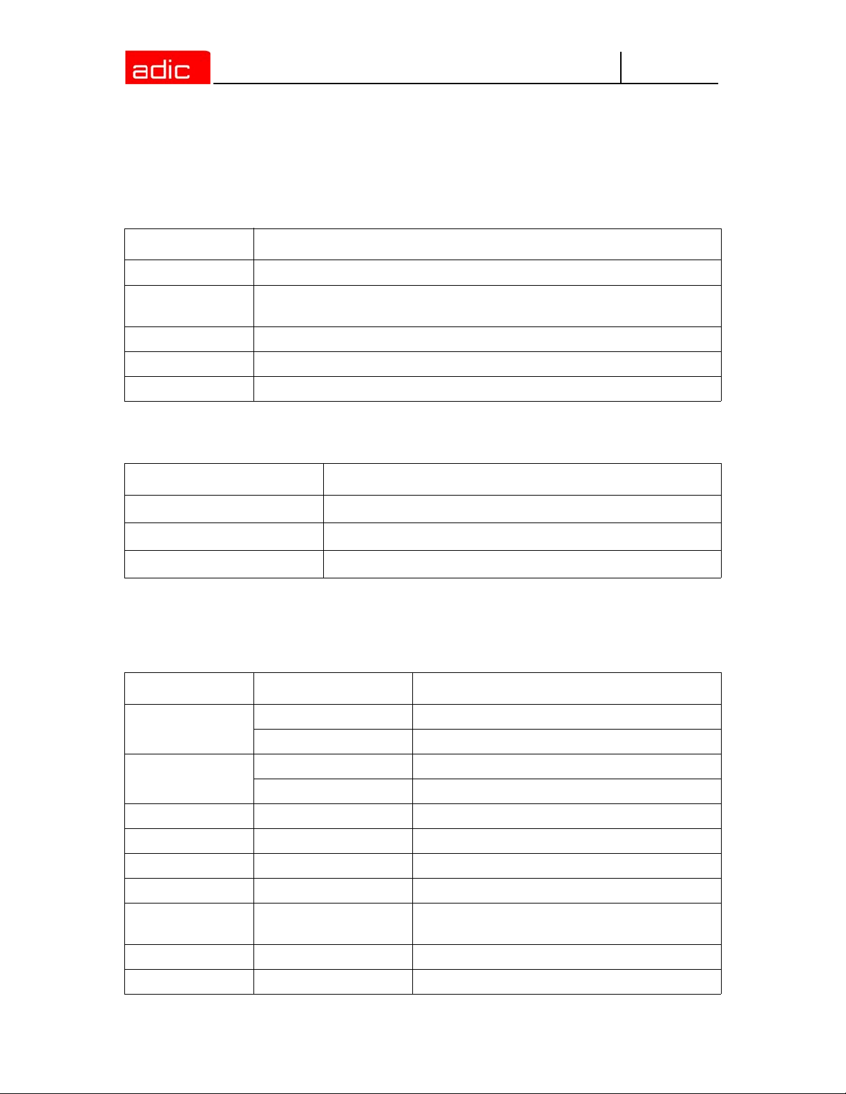
Organization
This publication contains the following chapters:
Chapter 1
Chapter 2 Description - Description of the functions of the AML Management Unit
Chapter 3
Chapter 4
Chapter 5 Utilities - Utility programs for diagnosis and installation of AML Systems
Chapter 6 Procedures - Description of important procedures (start, software update, etc.)
Chapter 7
Chapter 8 Messages - Log messages of AMU.
Appendix A Appendix - Glossary, trace level, media and device types.
Index
Introduction - Information concerning use of the manual as well as safety
instructions.
Operating Console - Explanation of functions of the AMU operating console
(CON)
Configuration - Explanation of the configuration features for AMU (AMU and
OS/2)
Useful System Functions - Information on OS/2 operating system, database
manager and TCP/IP functions in connection with AMU.
Explanation of Symbols and Conventions
The following symbols and highlighted passages note important information:
Symbol Damage to... Signal Word Definition Consequence
Person WARNING:
Material CAUTION:
NOTE:
Intended Audience 1-1
Imminent hazardous
electrical situation
Potential damaging
situation
Indicates important
information that helps
make better use of
the system
Death or serious injury
Possible damage to the
product, data, or
environment
No hazardous or
damaging
consequences
Page 14

The following is a list of formatting conventions used throughout this document:
• headline, for example, Chapter 2, Description
Italics
Helvetica term appearing on the operating console of AMU
Bold • Special Term, for example, Utilities
• filename, e.g. amuconf.ini
• variable, e.g. client_name
line or term appearing in an input window
AMU
Courier
[Courier] optional parameter
Param1 | Param2 alternative parameter
(dism) abbreviated command
• program message
• command
• parameter or file
Associated Documents
This manual contains references to following documents:
DOC E00 003 AMU Installation Guide
DOC E00 018 AMU Problem Determination Manual
DOC E00 014 AML-Controller User Guide
DOC F00 018 HACC/DAS Administration Guide
Customer Assistance
Advanced Digital Information Corporation (ADIC) provides the following types of customer
assistance for the AMU.
Technical Assistance
Telephone and e-mail support, as well as training for the AMU, is available through ADIC.
Contacting Support
Depending on how the technical support is purchased, telephone support is provided either through
your reseller or directly through ADIC.
The ADIC Technical Assistance Center (ATAC) provides world-wide service and support.
In the USA 800.827.3822
World-wide free call 00.800.9999.3822
In the Germany 49.07332.83458
Phone number 0033-(0) 130875300
Fax number 0033-(0) 130875301
Send email to support@adic.com
1-2 6-00440-02
Page 15
AMU
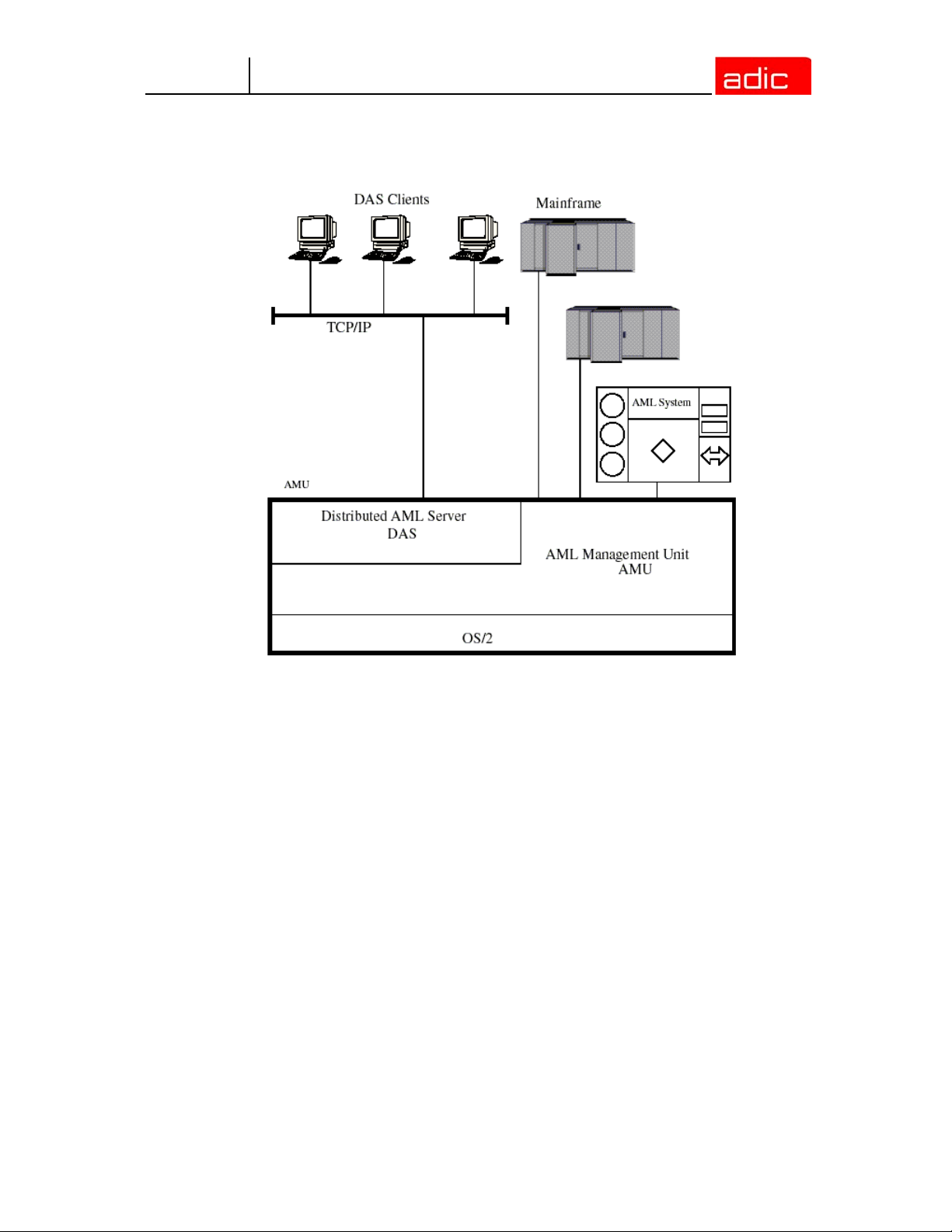
Description
Figure 2-1 AMU in a Multi-Host Environment
The AMU:
• is the main processor of the AML Mixed-Media Library (for each AML one AMU is required),
• is the central interface of the unmanned AML system,
• conducts the configuration service for hardware related AML functions,
• can be connected to several hosts,
• manages a database (SQL database DB/2 for OS/2) for;
• assignment of volsers to compartments,
• cleaning media,
• groups for rewritable media (scratch pools),
• is the hardware on which the following programs are running;
• AML Management Software (AMU),
• Distributed AML Server (DAS) (optional for connection of Distributed AML Clients),
• can be connected to a second AML to enhance the failure safety (DUAL AMU).
With the appropriate configuration, AMU can control various kinematics:
•AML/2
2-1
Page 16

•AML/E
•AML/J
AMU
NOTE:
The AML Management Unit (AMU) is described in the following chapters. The
information on DAS can be found in the following manuals:
• DAS Administration Guide
• DAS Interfacing Guide
AMU Tasks
The following section describes the various AMU tasks.
Command Management
AMU accepts commands from various interfaces:
• host interfaces
• graphic operating console on AMU processor (Refer to Operating Console on page 3-1)
The commands are either processed immediately and acknowledged (e.g. database queries) or
entered on a command queue according to priority. The software can enter up to 240 commands
on the command queue. All important events related to these commands are recorded in a log file.
AMU 3.12 accepts "foreign” cartridges from the I/O unit. You must, however, keep this compartment
empty for the dismount procedure.
Dismount Management
Dismounting includes:
• the unload command to the drive
• the process inside the drive preparing the unloading (e.g. rewinding tape drives)
• the dismounting (medium is moved to dismounting position)
• the robot command to move the medium from the drive to a new position (e.g. home
position)
These procedures can take different amounts of time depending on the drive type. With the aid of
the Dismount Manager these procedures can be adapted to the different drive types, and can be
controlled even if there are time differences for dismounting. (Refer to Drive on page 4-15)
AMU supports Drive Control Interface (DCI) for some types of drives.By means of this interface, the
AMU can get drive status, send unload commands and handle clean request from drive.
Supported drives and required DCI unit hardware
The following drives are supported in current release of the AMU software.
2-2 6-00440-02
Page 17

AMU
Drive DCI hardware version Notes
Quantum DLT ver. 4 or above
Quantum SDLT ver. 4 or above
IBM LTO ver. 4 or above
IMB LTO 2 FC ver. 4 or above
IBM 3590 ver. 4 or above
SONY AIT-1 ver. 4 or above
SONY AIT-2 ver. 4 or above
SONY AIT-3 ver. 4 or above
Require a special connection cable
(part no. 407000529)
Clean Management
In an AML some drives may require cleaning. The following modes are differentiated:
• drive is cyclically cleaned manually
• drive is cyclically cleaned automatically using a cleaning medium
• drive is cleaned manually as needed
• drive is cleaned automatically as needed
To determine the cleaning mode required for your drive refer to the drive´s documentation or ask
the drive´s manufacturer.
Clean Management supports cyclical automatic cleaning and automatic cleaning as needed.
Cyclical cleaning is based on a count of the mount procedures.
NOTE:
The cleaning cycle for the drive in the archive is individually adjusted for each drive. When cleaning
is required, the Clean Manager selects a cleaning medium from the clean pool.
The clean pool is the amount of cleaning media of a certain type, and each medium in the clean
pool has a barcode label. Required parameters are assigned by means of the clean pool, such as
maximum number of uses and minimum number of cleaning media required.
The clean pool is filled by special insert commands for cleaning media. The application receives a
message when the number of available cleaning media drops below the minimum amount. The
eject command for cleaning media is used to eject exhausted cleaning media.
In addition to this cyclical cleaning the application also offers a command for immediate cleaning of
a drive.
DCI-connected drives send the clean request via DCI interface to the AMU (except for the IBM 3590
drive, which does not support this). Thus Clean Manager cleans the drive only in the correct
procedure.
AMU Tasks 2-3
If your application should support cleaning of drives as needed or cleaning
based on the read and write procedures of the drive, use this version.
Page 18

AMU
Import/Export Management
In AML systems, ranges and units are defined for import and export of media. AMU differentiates
these according to the type of I/O unit:
• import and export without stopping the robot
• import and export while stopping the robot (I/O unit/D -HICAP AML/J);
As well as according to the type of host connection for import and export:
• host-controlled
• AMU-controlled.
Host-Controlled
When the operator presses a push-button to request the I/O unit, it then becomes unavailable for
the system (I/O unit cannot be used by the robot while operator is active).
After release by the system, the operator opens the I/O unit and removes the media from the I/O
unit as well as puts other media into the I/O unit.
When the I/O unit has been closed, it is automatically made available to the system.
Robot activities designed to check the changes made, are started by commands send by the HOST
software (HACC/MVS).
AMU-Controlled
When the operator presses a push-button to request the I/O unit, it then becomes unavailable for
the system (I/O unit cannot be used by the robot while operator is active).
After release by the system, the operator opens the I/O unit and removes the media from the I/O
unit as well as puts other media into the I/O unit.
When the I/O unit has been closed it is automatically made available to the system. AMU starts
checking the open ranges. Movement of media (filing in a storage area) is triggered by a host
command.
Foreign Mount
In the I/O unit a range for direct mount can be reserved (without insertion into archive shelves or
towers). The media stored there do not require a barcode label for identification. The assignment is
made via the compartments and virtual volsers (e. g.*FR001).
Database
The information on compartments in the archive and the media in the archive is saved in a relational
database. Such information includes:
• serial number of the medium represented by a barcode (VOLSER)
• kind of coordinate (CTYPE), e.g., whether a cleaning or data medium can be stored on this
coordinate
• qualities of the coordinate (CATTR)
• is it occupied or empty
• has the Volser just been mounted on a drive
2-4 6-00440-02
Page 19

AMU
• how often has it been used (USECOUNT)
• which robots have access right (COWNER)
• type of media that can be stored on this coordinate (MEDIA)
• backup status in case a DUAL-AMU is used (BUDSTATE)
• time of the last change (TIMESTMP)
• status of the medium, e.g. scratch (VTYPE)
• number of uses of the medium/drive for drive cleaning (COUNTER).
The AML database consists of three tables:
• COORDINATES (compartments in the archive)
• SCOORDINATES (drives and I/O unit)
• POOL (scratch media, cleaning media and data for Media Identifier convertion).
The database is automatically accessed with every host command.
Archive Organization
The table COORDINATES can be configured for various applications:
• Hierarchical Archive Organization
Volser are assigned to coordinates in increasing order. To allow for this, ranges (Volser
ranges) are defined when the database is set up, and the data records are preassigned.
A Volser can be stored in the system only if it is within a Volser range and therefore has a
home coordinate (home position). Identification is made automatically with the aid of the
barcode label on the storage medium.
• Dynamic Archive Organization
no fixed assignment of coordinates and Volsers upon setup of the database. Volser are filed
in random order in the archive (this type of organization is recommended if the Volsers in
the archive change frequently).
If a Volser as yet unknown to the system is inserted, it is automatically inserted at the first
vacant compartment in the dynamic range. This compartment remains the home position
of the Volser until it is ejected from the system with the "Eject Total” option.
• Dynamic Archive Organization with HACC/MVS
The host software HACC/MVS runs its own archive.When a new Volser is inserted into the
system, the target coordinate (new home position) is assigned by HACC/MVS.
This system also differentiates temporary and total ejection.
In one archive several organization principles may be used in combination (e.g. 1st range dynamic,
2nd range hierarchical).
Data Safety
The AMU plays a key roll in the connection between host systems and the robot system. An AMU
failure leads to a standstill of the entire robot system.
DUAL AMU
DUAL AMUs are two identical computers for control of ADIC archives (AML/2, AML/E, AML/J with
serial PMAC). The AMU computers are connected to the control units of the archives by means of
Automatic Data Switch (ADS) via an RS232C connection.
AMU Tasks 2-5
Page 20
AMU
The ADS is a remote-controlled switch creating the connection between AMU PC and control
components. If one AMU fails, a command shifts the switch and processing is resumed by the
second AMU.
The two AMU computers are linked by an RS232 interface or a LAN. This connection is used to
• synchronize the databases
• transfer commands (routing function)
• transfer configuration data (command controlled).
For the host systems the DUAL AMU is a single system (not two separate computers). The
information on which of the two AMU computers is currently holding the connection to the robot
control unit, is irrelevant for the function. Both AMU computers can receive host commands.
The commands are automatically sent to the active AMU and the robot control unit.
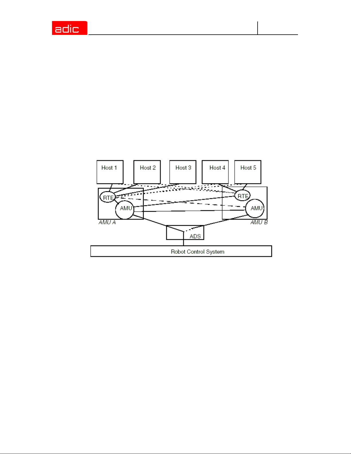
Figure 2-2 Functional Principle DUAL AMU
If the AMU (AML Management Unit) fails, the router (RTE) continues to run. In the example (shown
in Figure 2-2) there is no change in Host-AMU-communication when AMU fails on AMU A. Only the
ADS is switched by the switch command and the router of AMU A sends the host commands to the
AMU of AMU B. If AMU A fails entirely, the router is likewise no longer available. In this situation
the host-AMU-communication must be changed. Since host 3 in the above example is not
connected to AMU B, it would not be able to control the AML system if AMU A fails entirely.
Database Backup
Independent of the DUAL AMU, a constant, current backup of the database can be created: the
database backup (Refer to Process Configuration on page 3-19).
You can switch the database backup function on or off with an entry in the configuration file
AMUCONF.INI (Refer to Process Configuration on page 3-19).
By means of an entry in the configuration file you can determine where backup and journal files will
be saved.
You can write these files
• to a second physical hard disk in the AMU PC
• via the IBM-LAN-Requester to a LAN server (accessory). This would also provide
protection from possible disk crashes
2-6 6-00440-02
Page 21

AMU
NOTE:
The database backup starts once per day: when AMU is idling ("Idle Time”) at a programmable time.
The backup runs as an independent task in the background, that is, while the system operates. All
data records in the database are written to an ASCII file in their entirety (complete backup).
Additionally, all current changes are protocolled in separate files (journal files).
Since the database backup is created outside the database system, it will remain available for
restoration even if the database manager fails.
You can completely restore a database. You must have the following
• backup file
• corresponding journal file
on the AMU operating console in menu Service the command Restore (Refer to Restore on page
3-28). During the restoration, the backup and journal files are checked for integrity.
If a LAN server is used, the function of the network must be guaranteed. A
functional defect in the connection to the LAN server can cause a failure of AMU.
Also, after interruption of the connection to a LAN server (e.g. after shutdown of
the LAN server) manual intervention for sign-on to the LAN server is required.
Log Function
The activities of the archive software on the AMU computer (AMU, DAS) are recorded in the AMU
log.
For each day (beginning at 0.00 hours) a new log file is opened. The log file is written into a defined
directory (preset to: C:\AMU\LOGS-TRC). If the available storage capacity drops below a defined
value (preset to 40 MB), the oldest log files are deleted.
The log files are saved in ASCII format and can be read with any ASCII viewer.
Disaster Recovery Support
After a failure of the entire data processing center (host and disk storage), some media are
immediately required from the archive, to be able to continue operating with a spare data processing
center (Disaster Recovery). Since the host and therefore the software for control of the AML system
is not longer available in this case, the export is controlled by AMU. Refer to Ejection Procedure for
Disaster Recovery on page 6-5.
Host Connections
Host connection is made either
• directly by AMU (mainframes)
• or by DAS (Distributed AML Clients).
AMU as Server
In environments with several hosts, AMU operates as a server. It takes over the entire coordination,
since several host computers can access the AML system in parallel.
AMU Tasks 2-7
Page 22
AMU
To enhance fail safety of the system, two AMU computers can be connected to one AML system
(DUAL AMU).
The corresponding host software components communicate with AMU via various connections.
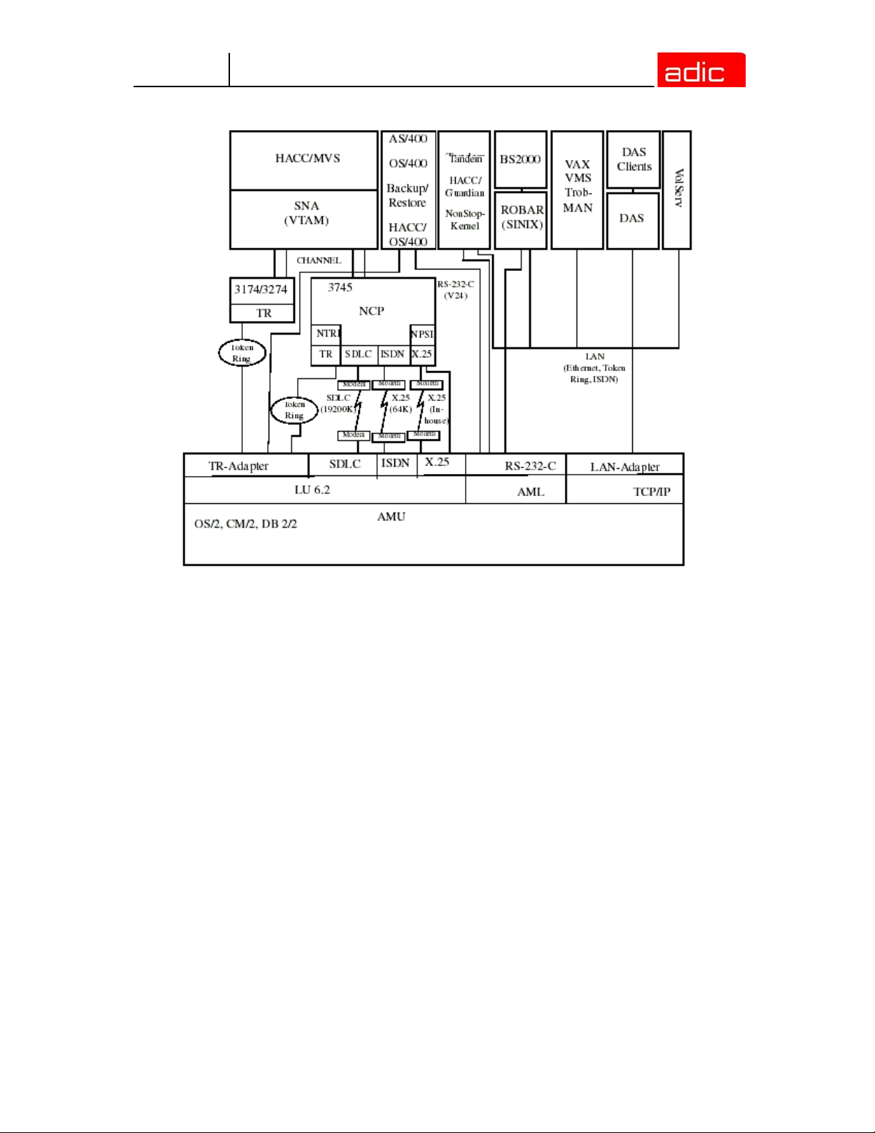
Selection and Number of Connections
The connection types available for the respective host type are described in the table below and the
diagram in this chapter.
The number of possible parallel host connections to AMU is limited only by the AMU hardware. If
the version does not provide what is required, select the next higher hardware version.
The AMU hardware currently employed can be used for systems with up to three physically differing
host connections (e.g. Token Ring, and Ethernet Connection).
Host Host Software
IBM - MVS HACC/MVS
IBM - VM/VSE HACC/VM/VSE
Siemens BS2000 ROBAR (BS2000)
IBM - AS400 LMS (M&T Consults)
Tandem TwinATL
UNIX HACC/DAS
DEC HACC/Open VMS
Limitations
In an environment with several hosts the following limitations apply
• one Token Ring connection with n x LU 6.2-connections in parallel
• simultaneous connection of HACC/MVS and HACC/VM:
• HACC/MVS via LU 6.2
• HACC/VM via LU 6.2
• as an option: TCP/IP via Ethernet
• as an option: AML via RS-232-C.
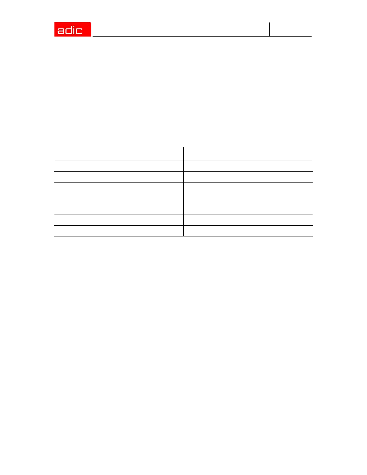
Connecting Options
The following chart provides an overview of the various connecting options.
2-8 6-00440-02
Page 23
AMU
Figure 2-3 AMU Connecting Options
Access Rights
Access rights to the functions of the AMU software are assigned to different levels.
Access to AMU Operating Console
Three user groups are differentiated:
• supervisor - system technician with full access rights to the system
• administrator - system administrator and task preparation has access to system
configuration
• operator - system operator, user of the system, without access to configuration.
Database Access
Authorization for database access is automatically made with the user identification "AMUADMIN.”
AMU Tasks 2-9
Page 24
AMU
AMU Processes
The software consists of individual programs (processes) running in parallel (multi-tasking). Each
process accomplishes a specific task. Additionally, there are various service utilities.
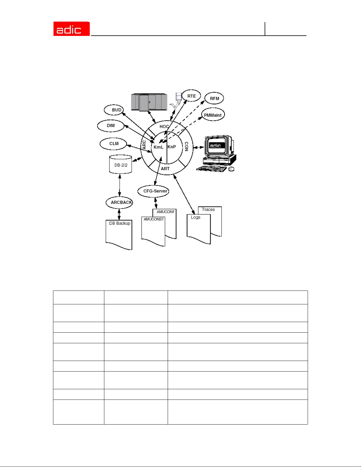
Figure 2-4 AMU Processes
Functions of Processes
The following table lists all functions and processes of AMU.
Abbreviation Name Explanation
Arc Archive
ArcBack Archive-Backup short-term, writes backup file
ART Alerter writes logs and traces
BUD Backup Daemon
Clm Clean Manager monitors cleaning of drives
Con
Dim Dismount Manager monitors drive cleaning
Hoc
2-10 6-00440-02
AMU Operator
Console
Host and other
Communication
manages and protocols (journaling) archive
catalog; SQL database
background process for control of data transfer
between DUAL AMUs
operator interface for application, installation and
maintenance
process controlling the communication to all
external systems (e.g. HACC/MVS, robot control
unit of AML/2)
Page 25
AMU
Abbreviation Name Explanation
KRN-L Kernel-logical
KNP Kernel-physical processing for robot (compute coordinates)
RTE Router
central logic, converts host commands to control
commands
set up routing table,
passes host commands from passive AMU
computer to active AMU computer and back
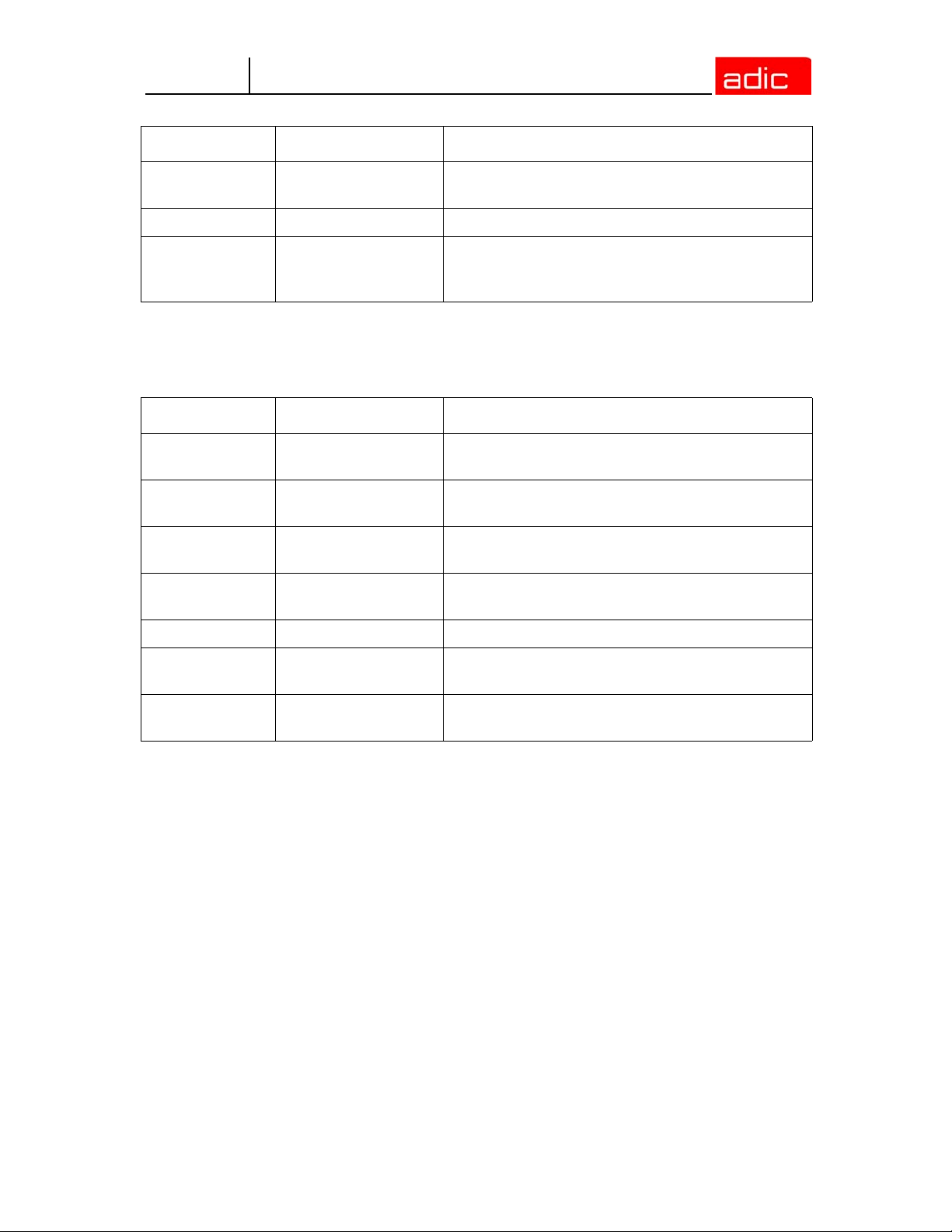
Service Programs
The following table lists all AMU service programs.
Abbreviation Name Explanation
INI2CONF AMUINI Converter
JustUtil JustUtility
Log2Asc Log to ASCII
PmMaint PMAC Maintenance
converts AMUINI.IN file in AMU version 2.00 to
AMUCONF.INI
editor for teach point files for AML/2, AML/J, and
AML/E
converts binary coded log file from AMU version
2.4 and earlier to ASCII file
microcode download and diagnosis program for
AML/J control unit (PMAC)
patini patini allows editing of binary configuration files
RFM Rho File manager
showini showini
file transfer to rho control when Kernel, HOC and
ARC (incl. DB 2/2) have been stopped
displays binary-coded configuration file in ASCII
format
AMU Processes 2-11
Page 26
AMU System Requirements
This section describes the AMU system requirements.
Hardware
Hardware Required level
Processor min. Intel Pentium 350 MHz
AMU
Memory
Hard disk min. one hard disk with 850 MB free space (2 hard disks recommended)
Graphic adapter min. XGA, 1024 x 768
Input device keyboard and mouse / trackball
min. 64 MB RAM (128 MB recommended, required for systems with two or
more hosts)
Software
Software Required level
Operating system
Database manager
Communication
OS/2 4.0 with fixpack 15, MPTS 6.0 and TCP/IP 4.31
IBM DATABASE 7.01
TCP/IP 4.31
Compatibility
This AMU version requires the following host and control software versions:
Software Version Comments
AML/2 control unit
AML/E control unit
AML/J control unit 2.40D or higher
DAS 3.12
ROBAR V2.5 or higher V3.02 recommended
HACC/OS400 V2.2 or higher
HACC/MVS 3.0 PTF ZY30015
TwinATL S0308D20 or higher
HACC/VM 1.4.2
2-12 6-00440-02
2.20D or higher Standard gripper
2.30D or higher Parallel gripper
2.20D or higher Standard gripper
2.30C or higher Parallel gripper
older version does not support the DUAL- and
CLEAN function
Page 27
AMU
Operating Console
System operation is identical whether you input commands at the operating console of the AMU or
at the host. Each has the same access priority to the system.
CAUTION:
NOTE:
Especially when using the commands Put, Get, Look, and Teach, be
sure to prevent conflicts with host commands. If in doubt, restart the
AMU after using any of these commands.
After any change of the configuration, you must restart the AMU (AMU
and DAS).
Input at the AMU must be restricted to the following situations:
• host communication failure
• robot failure (manual update of the archive catalog after manual
interventions (Refer to Operator Guide)
• during installation
• during maintenance
All non-executable commands or options are displayed with a shadow.
3-1
Page 28
Application
Design and application conforms to the SAA standard.
It it operated with
• the keyboard
• the mouse
Further information can be found in the OS/2 manuals.
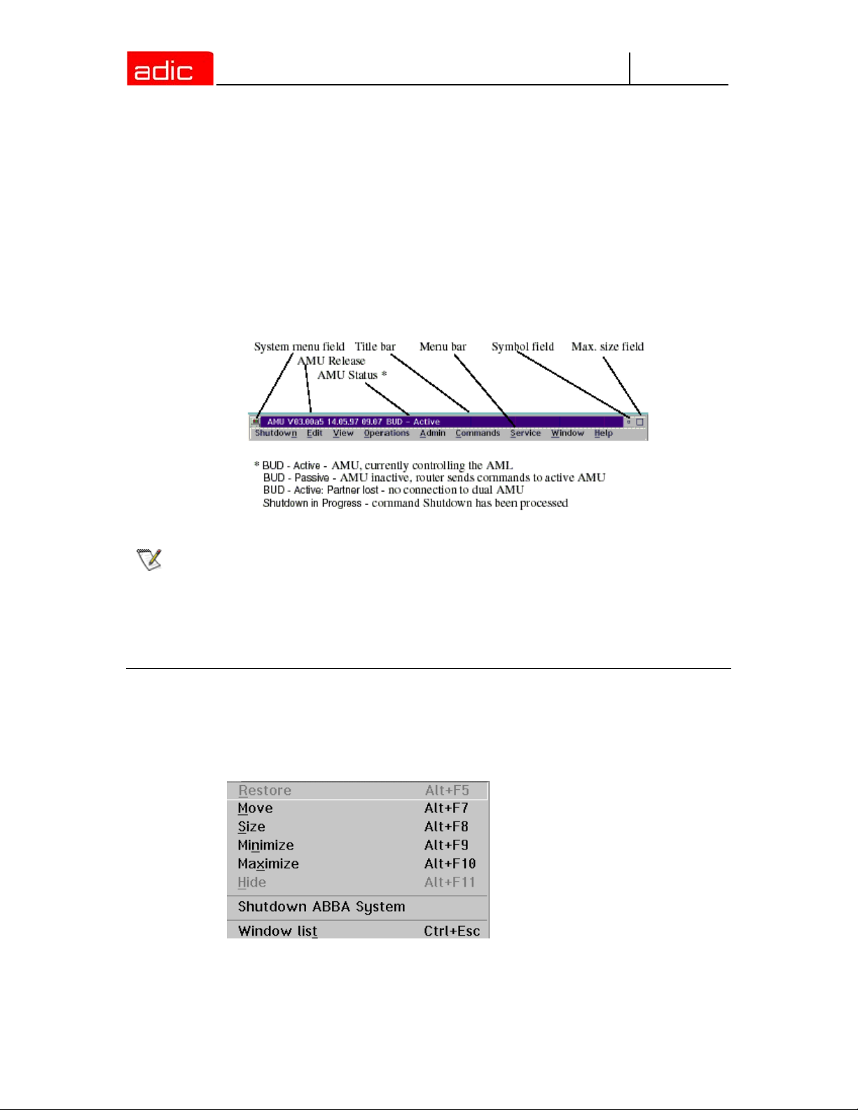
Design of the Menu Bar
Figure 3-1 AMU Menu Bar
AMU
NOTE:
The following functions are the same in all windows:
Button Function
Cancel Cancels the current function and closes the window.
Help Opens online help.
In the active window the title bar background is dark; in inactive windows the title
bar´s background is light.
System menu field
Figure 3-2 System Menu Field of AMU
Selecting a Command
With the mouse
3-2 6-00440-02
Page 29

AMU
1. Move the mouse pointer to the desired menu in the menu bar.
2. Click on the menu; the menu opens.
3. Click on the command in the menu; the command window opens.
With the keyboard
1. Press the <ALT> key and the underlined letter in the menu bar. The menu opens.
2. Now press the underlined letter in the menu to select the command.
With a command code
1. If a key or a combination of keys is specified following the command you can directly select the
command with it.
Altering a Window´s Size
Resizeable windows have a frame all around (e.g. Trace window).
1. Move the mouse to any corner of the active window. The mouse pointer changes into a double
arrow.
2. Press the mouse button and pull the window to the desired size while keeping the mouse button
pressed.
Moving a Window
1. Move the mouse pointer onto the title bar.
2. Move the window while keeping the mouse button pressed.
Closing a Window
1. Close the window by a double click on the system menu field.
Application 3-3
Page 30
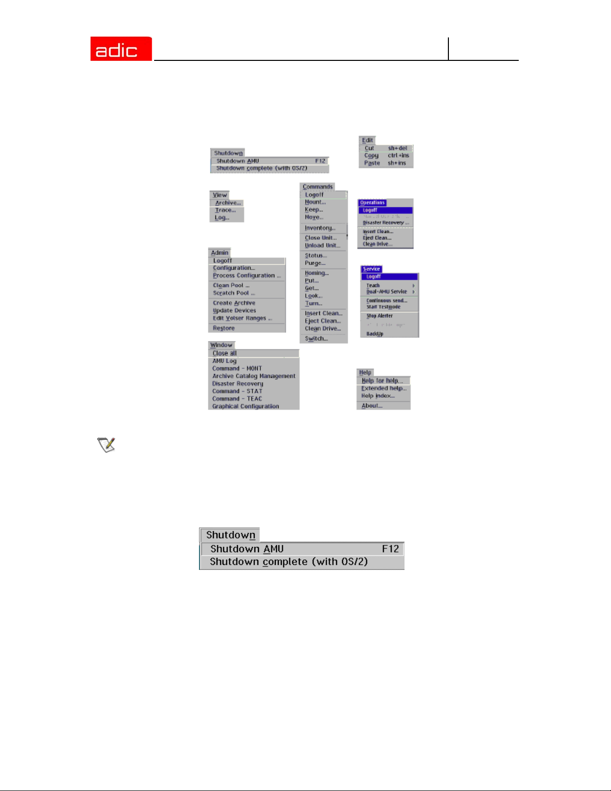
Overview of Menus
All commands of the AMU operating console are explained here:
Figure 3-3 Overview of Menus of AMU
AMU
NOTE:
When DUAL AMU is used, only the command Switch can be processed by the
passive AMU (even the command View Archive Catalog Management is not
allowed for the passive AMU). Enter all commands at the active AMU.
Menu Shutdown
Figure 3-4 Menu "Shutdown”
3-4 6-00440-02
Page 31

AMU
Command Field Explanation
Shutdown AMU Prepare shutdown of the AML system.
Before shutting down, interrupt the communication with the host computer
(e.g. with HOLD 1,1).
Short-cut: function key F12
Yes The current command will still be processed.
After that, all modules of the AMU will be terminated and
the database will be closed. Refer to the Operator Guide.
No Return to the program, no shut-down.
Shutdown
complete
(with OS/2)
Prepare to the shutdown of the AML system (like Shutdown only AMLSystem), thereafter terminate all processes running under OS/2 and
perform OS/2 system shutdown.
Before shutting down, interrupt the communication with the host computer
(e.g. with HOLD 1,1).
Menu Edit
Figure 3-5 Menu "Edit”
Command Explanation
Cut Cut the marked object and file it in the intermediate storage (computer main
storage).
Short-cut: press keys <Shift>+<Del>
Copy Copy marked object to the intermediate storage.
Short-cut: press keys <Control>+<Ins>
Paste Insert object from intermediate storage at the current cursor position.
Short-cut: press keys <Shift>+<Ins>
Menu View
Figure 3-6 Menu "View”
Calls up information in various windows.
Archive
Allows you to check and to change archive catalog entries for compartments.
Overview of Menus 3-5
Page 32

AMU
After input of a Volser or selection of a coordinate, all corresponding information in the database is
displayed. If a Volser occurs more than once, only the first entry in the database is shown.
Figure 3-7 Window "Archive Catalog Management”.
Field Explanation
Coordinate Logic coordinates of the medium in the archive. (One optical disk occupies two
logic coordinates, one for each side.)
The digits of the coordinates represent the following:
TT
NNSSRR
P
P
Compartment
Row
Segment
Device No.
Device Type
For the list of device types refer to Component Types on page A-9.
With the aid of the four selection windows, select the desired coordinate for
display of the data record of a coordinate.
3-6 6-00440-02
Page 33

AMU
Field Explanation
Volser Serial number of the medium, represented by a barcode, also referred to as
VSN.
Volsers are alphanumeric and between 1 and max. 16 characters long.
The following Volsers are not allowed:
• 0000000000000000
•CLEAN
Enter the Volser on the field to search the medium in the database.
MI Media Identifier for this volser.
The field will show only for systems which have active Media Identifier settings.
This field will not be shown for standard systems.
Also this field allowed for editing only for AIT, DLT, LTO media.
This new feature has been added for ADIC common barcode label support.
Medium Type of medium for monitoring of assignment of archive - drive.
Medium cannot be changed in the Archive Catalog Management.
Not all media types are generally differentiated even if they have the same kind
of housing.
Attribute Status of medium (the characters in brackets are the variables for the database)
Occupied (O) Compartment occupied by medium
Ejected (E) Compartment is empty, medium has been ejected
Mounted (M) Compartment is empty, medium is mounted in drive
Initial (I) Not used
In Jukebox (J) Compartment is empty,
Optical Disk is in the jukebox
Reverse Side
Mounted (R)
Empty (Y) Compartment is empty
Undefined (U) Undefined (special attribute for HACC/MVS)
Temp Away (T) On AML/2 twin-robot system the compartment in the storage
Temp Here (A) Occupied compartment in the problem box
Compartment is empty,
Optical Disk is mounted in drive (reverse side)
tower is temporarily occupied for transfer to the other robot
Overview of Menus 3-7
Page 34

Field Explanation
Type Type of compartment in the archive
Storage (S) Archive compartment for
• hierarchically-defined Volser ranges
• dynamically-defined Volser ranges, on HACC/MVS only
• no cleaning medium compartment
Clean (N) Cleaning media compartment
AMU
AMUDynamic (A)
Type of compartment in the I/O unit
Foreign (F) Foreign media compartment
Problem (P) Compartment in the problem box (I/O unit)
HACC-
Dynamic (D)
AMU-
Dynamic (A)
VType Volser type of storage media
• Undefined (U): Undefined (neither scratch medium nor scratch media
management on AMU)
• Scratch (S): Scratch medium
VType cannot be changed in the Archive Catalog Management. The value of this
field can be changed in the menu Admin with Scratch Pool or with a host
command.
Use Count Number of accesses to compartment.
Use Count cannot be changed in the Archive Catalog Management.
(not on HACC/MVS) archive compartment for dynamic insert
and transit
not used
Archive compartment for dynamic use of the I/O unit
Crash
Count
Robot
Access
Status
Message
3-8 6-00440-02
Not used
Access right of robot to compartment
AMU reply containing message number (refer to Useful System Functions on
page 7-1) after execution of a command has failed (e.g. Not found: RC = 1032)
Page 35

AMU
Commands
Command Explanation
View
Coordinate
View Next Display the archive catalog entry of the next coordinate of the component.
View Prev Display the archive catalog entry for the previous coordinate of the component.
View Volser Display the archive catalog entry for the volser entered.
Update Update the archive catalog entry for the archive coordinate. This command can
Display the archive catalog entry for the logic archive coordinate entered.
When the last coordinate has been reached no scrolling occurs.
When the first coordinate has been reached no scrolling occurs.
only be used after log on as administrator or supervisor.
The existing entry in the archive catalog will be overwritten. Wrong entries can
lead to discrepancies between the archive and the HACC/MVS archive catalog.
Trace
Online or offline protocol of internal processes of the AMU software (AMU and DAS). The records
can be selected by levels (AMU processes).
NOTE:
The selection of trace can slow down the processing! Change the selection only
after consulting ADIC Technical Support.
Standard selection: no traces.
CAUTION:
Figure 3-8 Window "Trace”
The memory for the current trace is limited. When failures occur you
must file the trace as soon as possible.
Field/Command Explanation
List of TraceIDs Trace levels can be selected with the <SPACE> bar or the mouse. For
the list of all trace IDs refer to Trace Levels on page A-3.
Overview of Menus 3-9
Page 36

Trace: Online The running trace is displayed on-screen with
•time
• trace ID (e.g. 03100 means trace KRN 1)
• trace entry (depending on type of trace)
Figure 3-9 Window "Trace” (Online)
AMU
OFF Switch trace off.
ON Write current traces into the main storage (1 MB reserved). When the
storage is full the oldest entry is overwritten.
Select All /
Unselect All
Filename Path and filename of trace in binary format, after processing the
Save Save protocolled traces in a file with the binary code name preset in field
All entries in the Online trace window are marked or the mark is removed
command Save
Filename.
Select this command immediately after a problem has occurred to
ensure the trace information is not lost. After formatting, this file can be
printed (refer to Format) with the OS/2 Print command.
3-10 6-00440-02
Page 37

AMU
Format Converts a trace file stored with Save into a printable format (ASCII).
Figure 3-10 Window "Format Trace Files”
Target filename (e.g. a:\name or c:\amu\logs-trc\name). Start formatting.
The execution will be confirmed by display of the message "formatted
100%”.
Infile Path and name of binary-coded trace file for conversion
to ASCII format (default: C:\AMU\LOGS-TRC)
Outfile Path and name of ASCII trace file after conversion to
ASCII Format
Start
Formatting
formatted Status display for formatting; when its shows 100%,
Start formatting process. Select this command after
your have entered the filenames in the fields Infile and
Outfile.
formatting is complete
Log
The alerter sets protocols for all messages (even when the window AMU-Log Control Center is not
open). Examples:
• host computer commands
• execution of host commands
• messages to the host computer
• user interventions
• error messages
Log files begin daily at 0.00 hours. If the available storage on the hard disk drops below the value
set in the configuration file ARTCFG.DAT (default 40 MB), the oldest log files are deleted (refer to
Configuration of AMU Log on page 4-50).
NOTE:
Log files cannot cover several days! There is only one log file for each day.
The first line in each log file contains the version number of the current AMU and, if DAS is installed,
the DAS version that is running.
Overview of Menus 3-11
Page 38

AMU
Figure 3-11 Window "AMU Log”
Field/command Explanation
Log archive Open a window for selection of stored log files with automatic display in
the OS/2 editor EPM. The log filename contains
lo <Day><Month>.001
Figure 3-12 Window "View Log Files”
View Copy the selected file into a temporary file (logview.txt).
This file is displayed in the OS/2 editor EPM and can be
processed as desired.
3-12 6-00440-02
Page 39

AMU
Fontsize Select font type, size and style for the contents in window AMU Log.
Figure 3-13 Window "Log Font Dialog”
Name Selection window for all installed font types
Size Selection window for font size in points
Style Selection window for font styles (available for some font
types only)
Display Selection of display fonts, does not change settings
Printer Not used
Outline Contour font
Underline Underlined font
Strikeout Strikeout font
Sample Display sample of selected font
Ok Activate selection for currently running AMU Log. When the
Menu Operations
Figure 3-14 Menu "Operations”
AMU Log window is opened again, the default font is again
displayed (System VIO).
Overview of Menus 3-13
Page 40

Login/Logoff (Operator)
Command Field Explanation
AMU
Login
(Operator) /
Logoff
If you wish to use the locked function in the Operator menu, you must log on
as operator, administrator or supervisor. To protect the system from
unauthorized use, logoff when you have completed operations
Password Field for input of the operator password. Request this
password from your system administrator
Ok Perform login.
Manual Operation
Precondition: ”MANUAL” operating mode
Manual execution of the host commands Mount (mount medium) and Eject (eject medium) by the
operator. This operating mode is designed exclusively for AML/2 with active Quadro towers.
NOTE:
AML/2 twin systems cannot run automatically and manually at the same time
AML/2 only
Step 1 On AML/2 switch the key switch on the operating panel to "MANUAL.”
Step 2 On AML/2 close all guard doors of Quadro towers. The quadro tower rotates but the
robot does not move.
Step 3 On AML/2 open the guard door to a Quadro tower and remove the medium.
Step 4 If a Mount command has been received, mount the medium on the drive indicated.
Step 5 Select OK to confirm the execution of the command.
Execution of the instruction is acknowledged to the host computer, and the latter
displays the next command.
The subsequent Keep is automatically acknowledged by AMU (database changed), but is not
displayed.
Step 6 If a Mount command for the same drive follows, remove the medium and put it into the
I/O unit.
Step 7 When resuming automatic operation, first insert all media used during MANUAL
operation.
3-14 6-00440-02
Page 41

AMU
Figure 3-15 Window "Manual Operation”
Command/field Explanation
Command Command from host to be executed by the Operator
Volser Search the Location according to the Volser or VSN, to be able to
execute the command.
Location Indicates the coordinate in the archive, where the Volser for the
command is currently located
Unit Number of storage tower or shelf
Segm. Number of segment in storage towers
Row Row in the segment (counted from bottom to top)
AML/2 only
Drive Mount the medium with the Volser in the drive given in this field. For
OK Select OK when the command has been executed by the operator,
Reject Select Reject when the command will not be executed by the operator.
Pos. Compartment (counted from left to right)
Name Designation (comment) defined in the configuration for the
component.
EJECT commands (eject medium) this field remains vacant.
Name Designation (comment) defined in the configuration for the
drive.
database update is performed, host receives positive confirmation.
Database update is not performed, host receives negative confirmation.
Disaster Recovery
Dialog window that starts ejection of preselected media in event of an emergency (Disaster
Recovery). This window has two areas for independent ejection of media in AML/2 twin-robot
systems.
Overview of Menus 3-15
Page 42

AMU
Figure 3-16 Window "Disaster Recovery"
Command/field Explanation
File Window for selection of prepared files listing Volsers to be ejected.
Display all files in the directory C:\AMU\RECOVERY\ with the filename
*.DSR (refer to Structure of the file on page 6-5).
Start Start the ejection of media listed in the selected file.
Stop Stop ejection
Status Display the current eject status
Insert Clean
Insert cleaning media.
Figure 3-17 Window "Insert Clean Media”
CAUTION:
Field Explanation
Pool Select the clean pool to which the cleaning media are to be added.
All media in the range are treated as cleaning media. Be sure there
are no data media in the insert range while this command is executed.
Logical Range Select the range into which you have put the cleaning media.
Eject Clean
Eject used cleaning media
3-16 6-00440-02
Page 43

AMU
Figure 3-18 Window "Eject Clean Media”
CAUTION:
Do not reinsert used cleaning media. If they are used beyond the
maximum Use Count, drive failure may result.
Field Explanation
Pool Select the pool from which to eject used cleaning media.
Logical Range Select the eject range into which the used cleaning media are to be put.
Clean Drive
Clean drive outside automatic cleaning process.
Figure 3-19 Window "Mount Clean Media / Clean Drive”
CAUTION:
The service life of some drive types is drastically shortened by
frequent cleaning. Clean drives only if it is definitely necessary.
Field Explanation
Drive Select drive to be selected
Overview of Menus 3-17
Page 44

Menu Admin
Figure 3-20 Menu "Admin”
Login (Administrator)
Command Field Explanation
AMU
Login
(Administrator) /
Logoff
If you wish to use the locked function in the Admin menu, you must log on
as operator, administrator or supervisor.
To protect the system from unauthorized use, log off when you have
completed operations
Password Field for input of administrator password. Request this
password from ADIC Technical Service.
Ok Perform Login.
Configuration
The Graphical Configuration window is used to enter all settings for system components. The
settings are saved in the file AMUCONF.INI.
3-18 6-00440-02
Page 45

AMU
Figure 3-21 Window "Graphical Configuration” example AML/J with DCI
Process Configuration
This screen provides an overview of system settings within the AMU and the abilty to set the
parameters for the database backup. All these parameters are saved in the file AMUCONF.INI.
Overview of Menus 3-19
Page 46

Figure 3-22 Window "Process Configuration”
AMU
Range Field Explanation
General Version Display current software release (parameter PROC VERSION).
FillSign Display which sign is used to complete the variables (e.g. Volser
to 16 characters) in the command string (default: <.>,
corresponds to ASCII 0x2E) (parameter PROC FILLSIGN).
MI Mode This button activate Media Identifier mode dialog. The button is
available for supervisor only. Refer to Media Identifier Mode on
page 3-22.
Kernel Load Display all processes started by the Kernel (parameter PROC
KRNLOAD).
• KNP: Physical Kernel Module
• UPM: User Profile Manager
• ARC: Archive Handler
• HOC: Host- and Other-Communication
• BUD: Backup Daemon
• RTE: Router
• DIM: Dismount Manager
• CLM: Clean Manager
Change This button activates the Change setting dialog. The button is
available for supervisor only. Refer to Change Settings on page
3-24.
3-20 6-00440-02
Page 47

AMU
Range Field Explanation
Database Parameter set used to create the SQL database upon execution of the command
Create Archive. Change these parameters only when you have been specifically
asked to do so by ADIC.
Database Name: Name of SQL database (parameter PROC DBNAME default:
ABBA)
Comment Comment on name in SQL database (parameter PROC
DBCOMMENT, default: ABBA/2 Management Unit Archive)
CodePage Information on codepage of SQL database (parameter PROC
DBCODEPAGE, default: 850)
Drive Drive on which the SQL database is stored (parameter PROC
DBDRIVE, default: C)
DatabaseBackup
File Backup Identifies the script used to execute the backup.
Path Directory and drive storing the backup and journal files.
C:\AMU\DBBACKUP is the standard directory. To have access
to the backup even when the AMU computer hardware is
damaged (e.g. hard disk failure), an additional hard disk can be
installed or files may be saved via LAN to another drive
(parameter PROC DBBACKUPPATH).
Active Switch on/off backup system (parameter PROC
DBBACKUPACTIVE).
FreeSpace Information on the storage management of the backup system.
If the vacant space drops below the set value in the directory
defined with Path, the oldest backup and journal files are
deleted (until the value for FreeSpace is again reached).
Information.
If the same drive is used for AMU and DBBACKUP, the value of
10 MB cannot be altered!
Start Start time for database backup. When the time is reached, the
system waits until the processor idles, the command execution
is then halted until the backup is complete (parameter PROC
DBBACKUPSTARTHOUR).
Script Path and Name of the backup script
Notification
Retry
Interval
Overview of Menus 3-21
Set the amount of time for the communication retries.
DUAL AMU
link lost
Insert clean
cartridges
Time in minutes (1... 120 minutes) default is blank
Time in minutes (1... 120) default is 5 minutes
Page 48

Range Field Explanation
Passwords Assignment of passwords for various AMU areas
Operator Password for call-up of functions in the Operations menu
(display is coded)
Administrator Password for call-up of functions in the Admin and Operations
menus (display is coded)
Supervisor Password for call-up of functions in the Service, Commands,
Admin and Operations menus (display is coded)
AMU
Disaster
Recovery
Cfg Log Write Switch selecting log write for configuration activities (parameter
HOC Recovery
Time
Barcode for
Service
Barcode OFF Allows you to operate the system (Mount, Keep, Eject) without
When scanner or vision system do not function, select this function until they are
repaired. As long as barcode reading is inoperative, media cannot be inserted
into the archive.
Password for call-up of the disaster recovery procedure (display
is coded). When the entry on this field is erased, the function
Disaster Recovery can be called up without a password.
PROC CFGLOG).
Time interval after which the communication module checks all
configured communication connections (parameter PROC
HOCRECOVERYTIME).
reading barcodes. For insertion and inventory barcode reading
is always active (parameter PROC BARCODEOFF).
Media Identifier Mode
Figure 3-23 Window "Media Identifier mode"
Field Explanation
Current setting Show current MI mode.
New setting This list box can be used for change MI mode
3-22 6-00440-02
Page 49

AMU
Field Explanation
Change The button can be used for apply MI mode changes. The user
has an additional opportunity to cancel changes through an
additional Media Identifier Mode confirmation dialog.
AMU supports media identifier (MI) for the following medias:
•LTO
•DLT
•AIT
AMU has the following states for MI processing:
• NORMAL. In this state AMU ignores MI information from the robot and show to the clients
the real barcode from the robot. In turn, the robot (on AML/2, AML/J, and AML/E, at least)
can be tuned in such way that it will strip MI information by itself, for example.
• REMOVE. In this case AMU detects MI information in volser , storse it in the separate table
and hides it from the clients. For example, LTO cartridge with volser 123456L2 will be
shown to the clients as 123456. When the client asks for mount volser 123456, AMU looks
in the table to find a volser with MI. When AMU finds it, the full name of this volser
(123456L2) is sent to the robot in the command with the full volser name.
• IN FRONT. In this case the MI information would be put in the front of the volser. For
example, LTO volser 123456L2 will be shown to the clients as L2123456. This mode was
implemented for compatibility with Scalar libraries.
Here are short rules to recognize MI:
• for LTO cartridges, if barcode has 8 chars and last 2 characters are "Lx" (where 'x' can be
'1','2','3' etc.) then this cartridge has MI information and 'x' stands for LTO media types (like
LTO-1, LTO-2, cleaning LTO etc.).
• for DLT cartridges, if barcode is 7 chars then the last chararacter is MI char.
• for AIT cartridges, if barcode is 7 chars then the last character is checksum.
Changes will applied immediately and can lead to change of volser
CAUTION:
representation for AMU and client programs! Change Media Identifier
mode ONLY if you need that.
NOTE:
This dialog is enabled for supervisor only.
Overview of Menus 3-23
Page 50

Change Settings
Figure 3-24 Window "Change settings"
This dialog change default (after restart) loading mode for DIM and CLM modules.
AMU
NOTE:
This dialog is enabled for supervisor only.
Clean Pool
Calls up a window for assignment of cleaning media to various groups (pools). A clean pool is a
group of cleaning media with the same qualities:
• Maximum number of cleaning cycles per medium
• Media type (e.g. 3480, 3590, DLT)
• Minimum number of cleaning media in the system
• Each individual drive can be assigned to such a pool
3-24 6-00440-02
Page 51

AMU
Figure 3-25 Window "Clean Pool Management”
Range Field Explanation
Clean Pool
Data
CAUTION:
Pools Display and selection field for all groups of cleaning media defined
in the AMU database. The standard names for these pools for
hosts that do not use clean pool names are Paa, aa being the
clean pool identifier.
Volser Display Volser in selected clean pool. The display only indicates
that the Volser has been assigned to the pool, but does not
indicate that the cleaning medium is actually present in the
archive.
The standard names for these Volsers for host that do not use
clean pool names are
identifier and
The volser with the standard names for cleaning media must
not be used as Volsers for data (CL0000 - CL9999). If the prefix
CL is used for data media, the parameter
CLMVOLSERHEADER in PROC in the file AMUCONF.INI can
be adapted after consulting ADIC.
bb the cartridge identifier.
CLaabb, aa being the clean pool
Overview of Menus 3-25
Page 52

Range Field Explanation
Pool Data Display data for clean pool marked in Pools
Pool Display selected clean pool. Enter the pool name on the field, to
set up a new clean pool
Watermark Display minimum number of cleaning media in the archive. As a
guiding value, take the number of drives to be cleaned from this
pool.
Media Cleaning media type; select media type used
Max Use Maximum number of cleaning cycles per cleaning medium. When
it has been depleted, the medium must be ejected. Enter the
value communicated by the drive manufacturer or cleaning
medium supplier.
Number Display media currently assigned to the pool
Available Display cleaning media inserted in the archive for the pool
AMU
Update
Pool Data
Delete Pool Delete pool with all corresponding data from the AMU database
Add Pool Add new pool with selected data to the AMU database
Volser Data Data for the cleaning medium selected in Volser
Volser Volser (VSN) of cleaning medium. Enter the Volser (barcode
Use Count Number of cleaning cycles performed with this medium
Update Use
Count
Delete
Volser
Add Volser Add Volser with preset Use Count to the pool
Refresh
Pool Data
Ok Terminates the dialog in Clean Pool Management
Information concerning the pool is updated in the window
Enters the changes made in the AMU database
number) for a new cleaning medium on this field.
Change the number of cleaning cycles saved in the database for
the selected Volser
Remove the Volser from the pool (not from the archive)
Scratch Pool
Calls up a window for assignment of storage media to different groups (pools). A scratch pool is a
group of storage media reserved by certain host applications.
3-26 6-00440-02
Page 53

AMU
Figure 3-26 Window "Scratch Pool Management"
Range Field Explanation
Scratch
Pool Data
Pool Data Display data of scratch pool marked in Pools
Pools Display and selection field for all defined groups of scratch media
in the AMU database
Volser Display Volsers in selected scratch pool. The display only
indicates that the Volser has been assigned to the pool, but does
not mean the storage medium is actually in the archive.
Pool Display selected pool. Enter the pool name on the field, to set-up
a new pool.
High Wate Display minimum number of scratch media in the archive
Media Storage media type, select media type used.
Number Display media currently assigned to selected pool
Available Display storage media available in the archive that bear the
attribute scratch and belong to the pool
Update
Pool Data
Delete Pool Delete pool with all corresponding data from the AMU database
Enters changes made in the AMU database
Add Pool Add new pool with selected data to the AMU database
Overview of Menus 3-27
Page 54

Range Field Explanation
Volser Data Data of the storage medium selected with Volser
Volser Volser (VSN) of the storage medium. Enter the Volser (barcode
number) for a new storage medium on this field. The medium is
assigned to the marked pool.
Scratch Display medium attribute scratch (Read Only field).
AMU
Delete
Volser
Add Volser Add Volser to the pool
Refresh
Pool Data
Ok Completes the dialog in Scratch Pool Management
Pool data is refreshed in the window
Delete Volser from the pool (not from the archive)
Create Archive
CAUTION:
The new archive catalog is created on the basis of the configuration data.
Confirm the warning and follow the process in the AMU log. The process is complete when the
message "Database AML now ready for use” appears.
This command creates a new archive catalog. The existing archive
catalog is irrevocably deleted!
Update Devices
Function for adaptation of the archive catalog to the graphical configuration. It must be used when
the kind and number of components has been changed.
Confirm the warning and follow the process in the AMU log. The process is complete when the
message "Database AML now ready for use” appears.
If a DUAL AMU is installed, the process must also run on the DUAL AMU after the configuration has
been transferred to it.
Edit Volser Ranges
Function for reassignment of compartments. The archive catalog is internally restructured rather
than recreated (refer to Configuration Of Volser Numbering on page 4-43).
Restore
Restore the archive catalog when the database backup system is on
NOTE:
3-28 6-00440-02
The database backup system saves the entire archive catalog daily at the time
entered in Process Configuration and protocols all changes occurring thereafter.
Changes by Edit Volser Range or SQL commands are not listed in the journal
file.
Page 55

AMU
Menu Commands
Figure 3-27 Menu "Commands”
Login (Supervisor)
All commands in this menu open the command window.
NOTE:
Command Field Explanation
Login
(Supervisor) /
Logoff
Information not required for execution of a specific command appears shaded
in the command window.
You can open several command windows at the same time.
If you wish to use the locked functions in the Command menu, you must log on
as operator, administrator or supervisor.
To protect the system from unauthorized use, log off when you have completed
operations
Password Field for input of the supervisor password. Request this
password from ADIC.
Ok Perform login.
Overview of Menus 3-29
Page 56

AMU
CAUTION:
The following functions are identical in all command windows:
All AMU commands in the commands menu are designed for test and
initial operation. Automatic operation is controlled by the host
computer.
In HACC/MVS systems, the archive catalog of the host computer
remains unchanged when these AMU commands are used. Improper
use can result in discrepancies in the archive catalogs.
Field Explanation
String: Display command string (refer to Command String Conventions).
Status Display messages, e.g. Cmd sent, rc 0 rc = Return Code:
• 0 = COMMAND in execution
• KRN response OK: command execution successfully completed
• error number, e.g. error from KRN 1033 (Refer to Messages in AML/2 Format
(AMU) on page 8-3)
Execute Execute command
Reset Prepare window for new command, no consequence for current command
execution
Command String Conventions
NOTE:
Figure 3-28 Command String Convention Part 1
The command string may contain fill characters ”.” (Default).
3-30 6-00440-02
Page 57

AMU
Figure 3-29 Command String Convention Part 2
Command "Mount...”
Mount the medium with the Volser indicated on the drive specified.
Figure 3-30 Window "Command - MONT”
Field Explanation
Command Selected command: MONT
Volser • Volser of the medium (e. . 123456)
• CLEAN (for mounting of first defined medium of type Clean)
• symbolic Volser (e.g. *FR001 or *11001) for foreign medium
Target Enter the target coordinates of the drive or the drive name (e.g. D01).
Command "Keep...”
Empty drive selected and return medium to its home position or a selected compartment, or turn
Optical Disk inside drive.
Overview of Menus 3-31
Page 58

Figure 3-31 Window "Command - KEEP””
Field Explanation
AMU
Command Selected command: KEEP
Source Enter the source coordinates of the drive or the drive name (e.g. D01).
Target
(optional)
Option
(optional)
Enter target coordinates only when
• you do not want to return the medium to its home position
• you want to assign a new home position to the medium
• you want to perform a drive swap
Only for KEEP of media type "Optical Disk”:
• FL: (Flip) The optical disk is removed from the drive, turned by 180° and then
remounted on the drive.
Command "Move...”
Move a medium from one compartment to another (new home position).
3-32 6-00440-02
Page 59

AMU
Figure 3-32 Window "Command - MOVE”
Field Explanation
Command Selected command: MOVE
Volser Volser only (read barcode and compare to database entry)
Source The coordinate of the Volser to be moved (if volser is omitted the medium is
moved without reading the barcode)
Target Enter the target coordinate or enter the logical eject range in the I/O unit (e.g.
E03). It will become the new medium home position. (For OD only coordinates
not resulting in turning of the OD are allowed)
Option Only for MOVE to the I/O unit
• JN: (Eject Normal) eject medium, but reserve compartment for the medium
(default, also used without option)
• JT: (Eject Total) eject medium and release compartment for a new medium
(Volser is set to zero-Volser).
Command "Inventory...”
Command for archive management:
• Read barcode of a compartment or several compartments and check the archive-catalog
entry
• Insert media (MOVE from I/O unit to archive)
Overview of Menus 3-33
Page 60

Figure 3-33 Window "Command - INVT”
Field Explanation
AMU
Command Selected command: INVT
Volser Enter the Volser if you want to check only one medium.
Source • the source coordinates if you want to check only one medium or one drive
• the start coordinate if you want to check an entire range
• a logic input range (e.g. I01)
Target Enter the end coordinates if you want to check an entire range.
Source and target coordinate must be on one "Device” (e.g. linear shelf, storage
tower). An inventory across several components is not possible with one
command. To perform such functions you can list commands with Continuous
send.
Option AI: (Automatic Insert) only for archive coordinates defined in AMU as "AMU-
Dynamic”. The Volser found (= read by the robot) is inserted if it has a home
position in the archive.
When you select option "AI”, enter only source coordinates of the type
"AMU-Dynamic.”
An Optical Disk in the I/O unit, with undetermined side A and B will not be inserted
if it does not have a home position in the archive.
When you select option "AU”, only the AMU archive catalog is altered. This
can result in differences between it and the archive catalog in the host. If the
scanner is failing, the real Volsers in the database are replaced by symbolic
Volsers (e.g. *I0001).
AU: (Automatic Update) only for archive coordinates of the archive. The Volser
found (= read by the robot) is automatically entered into the archive catalog. (The
existing entry is overwritten.) Empty compartments with the attributes "Mounted”
or "Ejected” are not altered. Only inconsistencies are protocolled in the LOG
Control Center.
3-34 6-00440-02
Page 61

AMU
Command "Close Unit...”
Close the drive cover of the specified 3X80 drive.
Figure 3-34 Window "Command - CLOU”
Drives supported:
• IBM 3480/3490 with cover
• Siemens 3590 with cover
Select this command if the robot has not closed the cover of the drive or if the cover has reopened.
Field Explanation
Command Selected command: CLOU
Source Enter the source coordinates of the drive.
Command "Unload Unit...”
Buttons on the selected drive are actuated by the robot (dismounting).
Overview of Menus 3-35
Page 62

Figure 3-35 Window "Command - UNLO”
Select this command to actuate the eject button on the drive.
Drives supported:
AMU
• all drives with eject button
NOTE:
(only for 3X90) After this command, the robot first grips the medium in the
"Mount” position during execution of the subsequent "Keep” command, to
unload a medium that may not have been drawn in by the drive. If this is not
successful, it then grips the "Keep” position.
Field Explanation
Command Selected command: UNLO
Source Enter the source coordinates of the drive or the drive name (e.g. D01).
Command "Status...”
Query and set the status of the robot or storage tower, as well as switch-over of the Automatic Data
Switch (if provided for).
NOTE:
Sign the robot back on with the option R1 (R2), if the robot reports "not ready.”
3-36 6-00440-02
Page 63

AMU
Figure 3-36 Window "Command - STAT”
Field Explanation
Command Selected command: STAT
Source Enter the source coordinates of the storage tower.
The source coordinate is always required for sign-on (ready) of a storage tower.
Option Enter the option:
• 10: robot 1 ready
• 20: robot 2 ready
• 11: robot 1 not ready
• 21: robot 2 not ready
• 0: tower ready
• 1: tower not ready
• A.: query versions
• Volser: AMU version
• Source: robot 1 version
• Target: robot 2 version (displayed in trace KRN1 only)
• R1: query robot and, if positive confirmation results, set robot 1 ready (ADS
switches connection over to control unit)
• R2: query robot and, if positive confirmation results, set robot 2 ready (ADS
switches connection over to control unit)
• QQ: Write all running commands from the AMU command queue in the AMU-
Log.
Please use this function in case of the message ***Kernel state mismatch*** or
if there are a problem with the command processing. The information is very
important for the problem analysis.
Overview of Menus 3-37
Page 64

Command "Purge...”
Purge a command not yet executed from the AMU command queue.
AMU
CAUTION:
Figure 3-37 Window "Command - PRGE”
Use this command only in exceptional cases. It can lead to
inconsistencies in the database.
Field Explanation
Command Selected command: PRGE
Data Select the command to be purged in the pop-up menu and purge the command
with Execute (e.g. CONKRN0332...):
• sender (CON)
• requester (KRN)
• sequence number (0332)
Command "Homing...”
Move robot to initial position (shut-off position).
NOTE:
When the robot has moved to its initial position, it reports "not ready.” The status
command can be used to set the robot to ready.
3-38 6-00440-02
Page 65

AMU
Figure 3-38 Window "Command - HOME”
Field Explanation
Command Selected command: HOME
Option Enter the robot number (1 or 2).
CAUTION:
Home is a low-level command. This command might lead to conflicts
with other host commands.
Before executing it, stop the host communication or perform Shutdown
AMU and startup before restarting production with the system (refer to
Switching the AMU Computer On on page 6-1).
Command "Put...”
Subcommand: put medium in position.
CAUTION:
The archive catalog is not accessed.
Overview of Menus 3-39
Page 66

Figure 3-39 Window "Command - PUT”
Field Explanation
AMU
Command Selected command: PUT
Target Enter target coordinates.
Option Enter:
• 1st digit (required parameter): the robot number (1 or 2)
• 2nd digit (optional parameter):
M: medium type D2 medium
S: medium type D2 small
Command "Get...”
Subcommand: get medium from position.
CAUTION:
The archive catalog is not accessed.
3-40 6-00440-02
Page 67

AMU
Figure 3-40 Window "Command - GET”
Field Explanation
Command Selected command: GET
Target Enter target coordinates.
Option Enter:
• 1st digit (required parameter): the robot number (1 or 2)
• 2nd digit (optional parameter):
M: medium type D2 medium
S: medium type D2 small
Command "Look...”
Subcommand: read barcode and check attribute.
Figure 3-41 Window "Command - LOOK”
Overview of Menus 3-41
Page 68

AMU
CAUTION:
The result is not compared to the archive catalog entry.
Field Explanation
Command Selected command: LOOK
Source Enter the source coordinates.
Option Enter:
• 1st digit (required parameter): the robot number (1 or 2)
• 2nd digit (optional parameter):
M: medium type D2 medium
S: medium type D2 small
Command "Turn...”
Subcommand: turn storage tower to segment. This command is only supported by AML/2 and AML/
E with storage towers.
Figure 3-42 Window "Command - TURN”
CAUTION:
The result is not compared to the archive catalog entry.
Field Explanation
Command Selected command: TURN
Source Enter the source coordinates.
Option Enter the robot number (1 or 2).
3-42 6-00440-02
Page 69

AMU
Command "Insert Clean...”
Insert cleaning media. Refer to Insert Clean on page 3-16.
Command "Eject Clean...”
Eject used cleaning media. Refer to Eject Clean on page 3-16.
Command "Clean Drive...”
Clean drive outside automatic cleaning process. Refer to Clean Drive on page 3-17.
Command "Switch”
When DUAL AMU is used, this command switches over from active to passive AMU.
Figure 3-43 Window "Switch”
CAUTION:
This command is reserved for test and service applications. Use the
command exclusively to check the switch-over function, or when there
is no other possibility to switch over (outdated host software without
switch command).
Field Explanation
Switch
(soft)
Switch force Upon execute, switch-over to the passive AMU occurs immediately regardless of
Upon execute, all running commands are completely processed, the databases
are synchronized; then only switch-over occurs.
possible data loss. Use this option only if AMU cannot be switched over any
other way.
Overview of Menus 3-43
Page 70

Menu Service
Figure 3-44 Menu "Service”
Login (Supervisor)
Command Field Explanation
AMU
Login
(Supervisor) /
Logoff
If you wish to use the locked functions in the Service menu, you must log on as
operator, administrator or supervisor. To protect the system from unauthorized
use, log off when you have completed operations.
Password Field for input of the supervisor password. Request this
password from ADIC.
Ok Perform log in.
Command "Teach single command”
Teach a single object, e.g. a tower segment or a drive.
CAUTION:
NOTE:
Transfer the changed teach-point file to the backup or DUAL-AMU
after teaching (only when available) (refer to DUAL-AMU Service: File
Transfer on page 3-47) and save the file on diskette
This is a complicated method of teaching. It is too cumbersome for initial
teaching of the entire system .
Use this command when teaching individual components.
.
3-44 6-00440-02
Page 71

AMU
Figure 3-45 Window "Command - TEAC”
Field Explanation
Command Selected command: TEAC
Source Enter the logic coordinate of the component to be taught.
Option Enter the parameter for closer specification:
• on AML/J only 1, 1N
• on AML/E only 1, 1N
• on AML/2
for robot 1 1, 1N
for robot 2 on twin systems also 2, 2N
• 1N or 2N: new-teach (All data of the component in KRNREFPT.R01 or
KRNREFPT.R02 or KRNREFPT.R00 are deleted. The target coordinates are
retrieved from the configuration. The entire component must be retaught.)
• 1 or 2: correction of the coordinates (the data from KRNREFPT.R01 or
KRNREFPT.R02 or KRNREFPT.R00 are corrected).
Command "Teach MTCGDialog”
Select this command from the menu Service - Teach. Graphically supported teaching, e.g. of a
Quadro tower, several drives or the entire system.
CAUTION:
Transfer the changed teach-point file to the backup or DUAL-AMU
after teaching (only when available) (refer to DUAL-AMU Service: File
Transfer on page 3-47) and save the file on diskette
.
Overview of Menus 3-45
Page 72

Figure 3-46 Window "Graphical Teaching”
AMU
Command Explanation
Connection Switch allowing you to display or to hide the connections
• Communication: data connection
• Access: mechanic access
Auto Update Deactivates update of connecting lines
Select All Select all components.
Unselect All Unselect all components.
3-46 6-00440-02
Page 73

AMU
Command Explanation
Teach Selecting a single component:
• teach (1): click once with the left mouse button - the component is shown
in red
• re-teach (1N): click twice with the left mouse button - the component is
shown in dark blue
To select several components keep <CTRL> pressed.
To define which robot teaches the component, mark the robot, the
component and the connection. If you teach drives, the system prompts you
for the teach rule.
robot 1 begins with the first tower in ascending order
robot 2 begins with the last tower in descending order
After teaching:
• component appears green: no errors
• component appears dark brown: error message and prompt
• Retry: teach once more
• Ignore: ignore failure and teach next component
• Abort: abort the teaching (all components)
Start Teach Start the teach routine for the selected components.
Stop Teach
(during teaching
only)
Stop the teach routine.
DUAL-AMU Service: File Transfer
Dialog for the transfer of any files (e.g. configurations data and database) to the DUAL-AMU or a
other computer in the TCP/IP network.
NOTE:
Precondition for the function is a TCP/IP connection.
Overview of Menus 3-47
Page 74

Figure 3-47 Window "File - Transfer"
AMU
Command/Field Description
Center this window moves the window to the center of the screen
Send mode opens the dialog for the file transfer from the local AMU to any other
computer
Receive mode not supported (Dialog for file transfer of any source computer to the local
AMU)
Exit ends the program File-Transfer
3-48 6-00440-02
Page 75

AMU
Figure 3-48 Window "File - Transfer Send mode"
Command/Field Description
Center this window moves the window to the center of the screen
Send mode selected
- Press here to reset
Reception directory
on target machine
Check target
machine directory
Open file dialog for
adding files
Clear listbox All files will be removed from the selection
Clear selected Only the marked files will be removed from the selection
Clear unselected Only the not marked files will be removed from the selection
Transfer All All files will be transferred to the target computer
Transfer Selected Only the marked files will be transferred to the target computer
stopps the dialog for the File-Transfer from the local AMU to any target
computer
Identifies the directory on the target computer, where the files should be
copied
checked, if the defined directory exist on the target system (New
directories will be not created)
May be used to configure one or more files for the transfer to the target
system. The files may be located in a different directory on the source
computer, but only in one target directory (during one file transfer).
The selection will be saved at the end of the program.
Transfer
Unselected
Overview of Menus 3-49
Only the unmarked files will be transferred to the target computer
Page 76

Command/Field Description
AMU
TCP/IP-addr.
(target)
User-ID Username for the FTP-support on the target computer
Password To the user ID-related password
Save&Activate
settings
Load&Activate
settings
Exit End the program.
TCP/IP-Address of the target computer
Settings will be prepared for the save in the file FILETR.DAT and for the
usage activated.
Settings will be loaded for the usage activated.
DUAL-AMU Service: Activate this AMU
This function changes the status of the local AMU from passive to the active Status, if the AMU is
currently passive.
Please use this command in case of a ADS malfunction or in case of problems with the status of a
not DUAL-AMU.
The function is available from AMU version 3.10C (refer to Release Notes).
Continuous Send
System test tool used without host: execute a single command or several commands in continuous
sequence. The commands are stored in the file "CONCONT.INI.”
NOTE:
The file CONCONT.INI from version 2.0 must not be used in version 2.2 or
higher (wrong format results in AMU software crash).
3-50 6-00440-02
Page 77

AMU
Figure 3-49 Window "Send multiple records continuous”
Command/field Explanation
Select and ... Commands executed with the marked command sequences in the range
List of Commands
Send one Execute the selected commands once (command
sequence).
Start Cnt Execute the selected commands continuously in a loop.
The item changes to Stop Cnt as the commands are
executed.
Stop Cnt Displayed only while a loop is being executed. Stops the
"Continuous send” after execution of the last command in
the loop.
Break Breaks the "Continuous send” after execution of the
current command.
Select All All commands in the field List of Commands are marked
and will be started when Start Cnt is confirmed.
Edit Process first marked command (command is entered on
the line for processing.
Delete Delete all selected commands.
Exit Quit the window "Continuous send” (the commands are
saved with Save to list and Save to list (before)
Overview of Menus 3-51
Page 78

AMU
Command/field Explanation
List of Commands Range for selection and change of individual command sequences
Save to list Add the command edited with Edit at the end of the list.
The commands are saved in the file CONCONT.INI.
Save to list
(before)
Results This window contains a log of commands executed. At the end of the
process, a statistic is displayed.
• Command processed - number of commands executed
• processing time (MIN, MAX,AVG) - time required per command
(maximum, minimum and average)
Add the command edited with Edit before the selected
command. The commands are saved in the file
CONCONT.INI.
Procedure illustrated with a "Move” command.
Step 1 Select Continuous send... (Service menu)
Step 2 Select Move... (Commands menu)
Step 3 Enter the parameters
• Volser
• source coordinates
• target coordinates
Step 4 Copy the command string (from the command window)
• select the command string (put the cursor at the beginning of the string and mark the
entire string keeping the left mouse button pressed)
•select Copy (menu Edit)
Step 5 Put the command string into the window Continuous send
• put the cursor on "List of Commands”
•select Paste (menu Edit)
Step 6 Select the command Save to list or Save to list before
Step 7 Select all commands to be executed
Step 8 Select Start Cnt or Send one. All selected commands are executed
Start Testmode
Switch for simulation mode: No processing of commands outside AMU. AMU processes the
commands as far as possible and confirms their execution to the host (positive acknowledgement).
3-52 6-00440-02
Page 79

AMU
CAUTION:
Command execution alters the archive catalog although no medium is
actually moved. Use only for test and training systems.
Stop Alerter
The alerter (program ART.EXE) writes logs and traces. Terminate the alerter, e.g. if you want to
copy an active log file to disk:
Step 1 stop the host communication (e.g. hold on HACC)
Step 2 select Stop Alerter
Step 3 copy the log file
Step 4 restart the alerter (open AMU log)
CAUTION:
When the alerter has been stopped no logs and traces are written.
Restart the alerter as soon as possible.
Rho File Manager
The Rho File Manager transfers files between the AMU and the rho control in both directions (refer
to Rho File Manager on page 5-1).
CAUTION:
After a safety query, the robot moves to its initial position and the AMU function stops (kernel is
terminated).
Stop the communication between host and AMU before calling up the
Rho File Manager.
Menu Window
Figure 3-50 Menu "Window"
Command Explanation
Close all Close all open windows.
Window (List of all open windows) Call up the respective window.
Overview of Menus 3-53
Page 80

Menu Help
Figure 3-51 Menu "Help”
Command Explanation
AMU
Help for
help...
Information on the use of the start page for help functions.
Figure 3-52 Window "Using the Help Facility”
3-54 6-00440-02
Page 81

AMU
Command Explanation
Extended
help...
Start page for AMU online help
Figure 3-53 Window "Help for AMU - (AML Management Unit)”
Help index... Help index
Figure 3-54 Window "Help Index”
Overview of Menus 3-55
Page 82

Command Explanation
About... Display copyright information and AMU version number.
Figure 3-55 Window About AMU”
AMU
3-56 6-00440-02
Page 83

AMU
Configuration
This chapter describes all configuration options within AMU.
Window "Graphical Configuration”
This window is used to configure all AML components.
In DUAL AMU systems, changes of the configuration must be made at the active AMU. Only
changes for dismount management, Clean Management and Logical Ranges for Insert/Eject will be
activated on a running system. For all other changes, you must be restart the AMU. AMU and DAS
must be down for direct changes on the configuration files (refer to PATINI on page 5-49).
Figure 4-1 Window "Graphical Configuration” (Example AML/E)
Window "Graphical Configuration” 4-1
Page 84

Field Explanation
Device Container Switch allowing to show/hide the window Device Container.
AMU
Communication Switch allowing you to show/hide the connections. Communication (black):
hardware connection
Access Switch allowing you to show/hide the connections. Access (green):
responsible = logic connection
DriveCount in Hex
Auto Update Automatic update of display contents after each change.
Save Save the configuration in AMUCONF.INI and save the old file to
Delete Delete the selected (marked in red) component from the layout.
Select All Select all elements (icons).
Exit Exit the graphic configuration without saving.
Switch for count mode of drive names (hexadecimal or decimal). Select
hexadecimal if more than 100 drives are involved (on HACC/MVS
HACCPARM parameter UNITNUM=HEX)
To switch over, click on the switch with the right mouse button.
CONFAMU.INI.
After saving the configuration file, transfer it to the backup or DUAL-AMU
(only if available) (refer to DUAL-AMU Service: File Transfer on page 3-47)
and save the file on a diskette.
The Configuration Procedure
This section describes the AMU configuration procedure.
4-2 6-00440-02
Page 85

AMU
Configuring a component
Step 1 Pull the desired component into the configuration window. Position the icon in the
configuration window by clicking the right mouse button and moving the mouse.
Step 2 Double click on the item to open the configuration window.
NOTE:
Only one configuration window at a time can be opened.
Deleting a component
Step 1 Mark the icon or connecting line you wish to erase by clicking on it (symbol is marked
red). Mark several symbols by keeping the <CTRL> button pressed.
Step 2 To delete all selected symbols, click Delete.
Defining connections
Step 1 Click on the first icon with the left mouse button, keep the mouse button pressed and
pull the mouse to the second symbol.
On AMU communication connections an icon is shown on the connecting line
(communication parameters).
Required connections
From To
HOST AMU
Drive
AMU Control units
ADS
Scanner (AML/J)
DUAL AMU
Drive container (Drive Control Interface)
Control unit Robot
Storage tower
I/O unit
Robot Drive
Storage tower
Linear shelves
I/O unit
Problem box
Saving the configuration
Step 1 After configuring, click Save.
Window "Graphical Configuration” 4-3
Page 86

Configuration Windows of Components
AMU
NOTE:
NOTE:
1. Click on Media Container. The window Media Container appears.
2. Pull the selected medium onto the desired segment or handling box with the right mouse button
pressed.
Figure 4-2 Window Media Container
The coordinates contain the name and the type of the respective component.
• name: 1st, 3rd + 4th digit of the coordinate
• type: 1st + 2nd digit of the coordinate
Example:
drive coordinate: D902010101 - name: D02 type: D9
For storage tower, linear shelf and I/O units the various media types can be
selected in the Media Container.
4-4 6-00440-02
Page 87

AMU
Host Computer
Figure 4-3 Window "Host Configuration”
Field Explanation
Name: Name of the component (H01, H02 …).
Description: Description of the component in the log strings.
Type: Component type (refer to Drives on page A-9)
AMU: List of connected AMUs.
Drive: List of connected drives.
Command
Look
Log. Ranges
Robot
Host is able to
set time
NOTE:
Window "Graphical Configuration” 4-5
Opens a window allowing you to lock selected commands for this host.
Insert Default area in the insert/eject unit, which will be used by this host for
insert if the host does not use the insert commant to specify another
area.
Eject Default area in the insert/eject unit, which will be used by this host for
eject if the host does not use the eject commant to specify another area.
With the ROSA or STATUS command, the system time of the AMU computer is
set to the value in the command string.
DAS/2 as host beginning with version 1.3 is no longer configured in the AMU.
Page 88

Command Look
Figure 4-4 Window "Host Commands Configuration”
AMU
Field Explanation
Actual Host Selection box for all host configured; for command configuration it does not matter
which icon you select to open the Host Configuration.
Possible
Commands
List of all commands that can be locked for individual hosts, in AML/2 and ABBA/1
format
Automatic
Mode
Cleaning HACC/MVS command for query and change of CLM parameters
Robot start Command setting the robot ready
Robot stop Command setting the robot offline and moving it to its home
Barcode off Switch off barcode reader for Mount and Eject
Barcode on Switch on barcode reader
Eject clean
media
Insert clean
media
Insert normal Insert storage media
Manual mode Switch to manual mode (operation without robot)
Terminate the manual mode (intermediate operation without
robot)
position
Eject cleaning media
Insert cleaning media
4-6 6-00440-02
Page 89

AMU
Field Explanation
Test mode Switch on AMU diagnosis operation (diagnosis without AML
system)
Mount clean
media
Eject normal Eject medium while keeping its home coordinate. Switch this
Eject total Eject medium and delete its Volser completely from the archive.
NTFY HICAP
request
NTFY Robot
is home
NTFY Robot
ready
NTFY Volser
available now
NTFY Volser
removed
NTFY Autom.
invent. ended
NTFY Start of
cleaning
NTFY Clean
successfully
NTFY Clean
failed
NTFY Clean
media required
Shutdown Shutdown AMU
Switch normal Switch-over to DUAL AMU without failure
Switch force Switch-over to DUAL AMU in case of failure
Download AMU database changed by host
Selection Change the selection only after consulting ADIC Technical Service.
Uncoordinated changes can lead to system failures.
Add Lock selected command for this host
Delete Unlock selected command for this host
Locked
Commands
Save Quit window after change of configuration. Save changes in window Graphical
Display locked commands
Configuration with Save to the file AMUCONF.INI.
Immediate drive cleaning
command off if this host operates exclusively with dynamic
archiving, or if you do not wish this host to perform ejects.
Switch this command off if this host operates exclusively with
hierarchical archiving, or if you do not with this host to perform
ejects.
Asynchronous information for request of I/O unit/D
Asynchronous information for shutdown of the robot (ROBS-OFFmessage)
Asynchronous information for power-up of the robot (ROBS-ONmessage)
Asynchronous information on inserted media
Asynchronous information on ejected media
Asynchronous information on end of inventory of I/O unit
Asynchronous information on cleaning of drive
Asynchronous information on cleaning of drive
Asynchronous error message on automatic cleaning of drive
Asynchronous information on missing cleaning media in AML
system
Window "Graphical Configuration” 4-7
Page 90

AMU
Figure 4-5 Window "AMU Configuration”
AMU
Field Explanation
Name: Name of component (A01, A02 …).
Externname: Name for the telegrams to the connected hosts (actually operates all hosts with
the name A01
Description: Description of the component in the log strings.
Type: Component type (refer to AMU on page A-13)
Local AMU Configuration of local AMU hardware.
Other AMU Configuration of AMU connected to local AMU.
Partner: List of connected communication partners.
4-8 6-00440-02
Page 91

AMU
Robot System
Figure 4-6 Window "Robot Configuration”
Field Explanation
Name: Name of the component (R01, R02). AML/E and AML/J always have only one
robot, AML/2 can have one or two robots.
Description: Description of the component in the log strings.
Type: Component type (refer to Robots on page A-12).
Controller: Connection to controller.
Access: List of units connected that can be accessed by the robot (green lines).
Window "Graphical Configuration” 4-9
Page 92

Control
Figure 4-7 Window "Controller Configuration”
AMU
Field Explanation
Name: Name of component (O01, O02 …).
Description: Description of the component in the log strings.
Type: Component type: refer to Control Units on page A-13.
AMU: List of connected AMUs (default A01).
Partner: List of connected units.
Scanner (barcode reading system, for AML/J only)
Figure 4-8 Window "Scanner-Configuration”
Field Explanation
Name: Name of component (S01)
Description: Description of the component in the log strings.
4-10 6-00440-02
Page 93

AMU
Field Explanation
Type: Reaction of scanner when problems occur
• S0 - scanner read error leads to termination of command with negative
acknowledgement
• S1 - scanner read error is ignored, command will be executed and
acknowledged positively
AMU: Indicates connected AMU
ADS (Automatic Data Switch)
• automatic switch-over between the DUAL-AMUs
• switch-over is prompted by a host command
Figure 4-9 Window "ADS Configuration”
Field Explanation
Name: Name of component (W01)
Description: Description of the component in the log strings.
Type: Component type
• W0 - ADS (SOTEC)
Partner: List of connected AMUs
Configuration of an AML System with DUAL AMU and Automatic Data Switch
Step 1 Insert a second icon "AMU” in the configuration.
Step 2 Insert the icon "ADS.”
Step 3 Create a connection from AMU(A) to AMU(B).
Step 4 Create a connection from AMU(B) to AMU(A).
Window "Graphical Configuration” 4-11
Page 94

AMU
NOTE:
Step 5 Create connections from AMU(A) to each Host.
Step 6 Create connections from AMU(B) to each Host.
Step 7 Create connections from AMU(A) and AMU(B) to each controller (Control Tower,
Step 8 Create connections from AMU(A) and AMU(B) to the ADS.
Figure 4-10 Window "Graphical Configuration” with DUAL-AMU and ADS
Check that one of the connections is from A01 to A02 and the other connection
from A02 to A01. This are necessary for display the actual connections of the
AMU. If nothing or both connections marked, create the configurations of the
connections anew.
Control Robot, Control I/O Unit/A).
Step 9 Set up the following values in the window AMU configuration
Field Parameter AMU(A) Parameter AMU(B)
Name: A01 A02
Externname: A01 A01
Description: AML Management Unit1 AML Management Unit2
4-12 6-00440-02
Page 95

AMU
Field Parameter AMU(A) Parameter AMU(B)
Type: A1-AMU with DUAL-AMU A1-AMU with DUAL-AMU
Other AMU
Local AMU
Step 10 On the PC AMU(A) create the file LOCAL.AMU in directory C:\AMU with the entry A01.
Step 11 On the PC AMU(B) create the file LOCAL.AMU in directory C:\AMU with the entry A02.
NOTE:
Step 12 Configure communication paths between
Step 13 Save the new adjustments with Save.
Step 14 Restart AMU.
✔
Use the same interfaces for AMU(A) and AMU(B).
•the AMUs
• AMU and Host
• AMU and Controller
✔
Meaning of the file LOCAL.AMU
The configuration parameters are saved on both AMUs. The assignment of the active
communication parameters is made using the AMU names (A01 or A02). This name appears in the
ASCII-file LOCAL.AMU in the directory C:\AMU.
Drive Folder (Drive Container)
Folder that allows you to arrange new or existing drives in a group.
Drives can be added to the folder by dragging with the mouse or with the command Generate.
NOTE:
Window "Graphical Configuration” 4-13
The connecting line from drive folder to robot must be drawn before the drives
are added to the folder. Otherwise the teach point data will be lost.
Page 96

Figure 4-11 Window "Container Drive"
Field Explanation
Description: Description of the component in the log strings.
Table with all drives defined in the container drive:
AMU
•drive type
• drive address (AMU)
• description (name for HACC/DAS clients)
When you double-click one line, the window Drive Configuration opens (see
Figure 4-13 on page 4-15).
Generate Call up the dialog window for generation of drive configurations from the container
drive (see Figure 4-12).
Close Close the window Container Drive.
Figure 4-12 Window "Generate Drive"
4-14 6-00440-02
Page 97

AMU
Field Explanation
Type: Select the drive type of all drive configurations to be generated in the container
drive (refer to Drives on page A-9).
Start Drive
Name:
Count: Number of all drives generated in the container drive (recommended maximum
Generate Generate drive configurations with the selected parameters
Enter name of first drive in the container drive. Depending on the inputs made in
the window Graphical Configuration the names are counted in decimal or
hexadecimal.
Generation of drive configurations is successful only when no other drives
are configured for the selected range of names.
number: 16)
Drive
Definition of drives in the archive with assignment of parameters for position in the archive, drive
type and further options for drive cleaning and error handling during dismounting.
Figure 4-13 Window "Drive Configuration”
Range Field Explanation
Name: Name of component (D01, D02 …, DZZ).
Window "Graphical Configuration” 4-15
Page 98

AMU
Range Field Explanation
Description: Description of the component in the log strings. For practical reasons, the drive
address of the host should be entered here (for drives in a DAS environment
max nine alphanumeric characters can be entered). See DAS Administration
Guide.
Type Drive type (refer to Drives on page A-9).
Media Type Automatic assignment of media type to drive
Teach
coordinates for
segment 1
Unload
Parameters
Dismount
Management
Clean
Management
Drive’s serial
number
HW info This button works only for DCI-connected drives and it opens the drive hardware
Arrangement Arrangement of drives in the system
R01 (R02)
X Y Z
General
automatic
unload
Unload after
cleaning
Rewind Time
(sec)
Eject Time
(sec)
Dismount
Management
Automatic
Dismount
Wait Time
(sec)
Number of
Retries
Automatic
Cleaning
Number of
Cycles
Clean Time
(sec)
Clean Pool Name of clean pool from which media are extracted for drive
Field "Drive's serial number" is available for reading/changing and it can be used
to assign any sequence up to 50 characters.
information dialog box. The description of all available DCI drives follows.
Basic teach coordinate (for first teaching - New teach)
Robot actuates the eject button (Get on drive) of the drive
(Unload)
Robot actuates the eject button of the drive prior to every Keep
of a cleaning medium (Unload)
Average time required from the command to eject the medium
from the drive until the medium is actually ready to unload.
Time required to eject medium.
Problem handling if irregularities with the drive occur (wait and
repeat the Keep command)
not used
Time between two attempts at unloading the medium from the
drive
Maximum number of attempts to unload the medium from the
drive. If the last attempt ends negatively, also, the command will
be acknowledged negatively.
Drive cleaning is controlled by the AMU. After each clean
command the AMU generate a KEEP of the cleaning cartridge.
(Cyclic or DCI controlled)
Number of Mount commands after automatic start of a cleaning
mount. Request this value from your drive manufacturer. For
DLT-Low Profile must the value "0" for DCI controlled cleaning
Average time during which cleaning medium will remain in the
drive.
cleaning.
NOTE:
4-16 6-00440-02
If a large number of drives is involved, use the symbol "Container Drive” for
drives connected to the same host and operated by the same robot. Refer to
Drive Folder (Drive Container) on page 4-13.
Page 99

AMU
The following figure illustrates the function of the Dismount Manager and the effect of the individual
parameters.
Figure 4-14 Dismount Manager Function Scheme
IBM 3590 drive parameters
Figure 4-15 Window "IBM 3590 drive hardware information"
Window "Graphical Configuration” 4-17
Page 100

AMU
Field Explanation
Drive name The drive name, as known to AMU
DCI addr. The DCI unit address
DCI port The DCI unit communication port number
Drive status The current drive status. Can be "ready", "cartridge in transit", "cartridge in
feeder slot", "load error" etc.
Cleaning status The drive cleaning status. Can be "ok" or "required"
IBM LTO drive parameters
Figure 4-16 Window "IBM LTO drive hardware information"
Field/Button Explanation
Drive name The drive's name, as known to AMU
DCI addr The DCI unit address
Communication
type
Firmware revision This field shows the firmware revision of the tape drive
SCSI ID The SCSI address of the drive (for IBM LTO SCSI drives only). The
AL_PA Arbitrated Loop Physical Address (for IBM LTO Fibre Channel drives only).
Host bus connection
srarus
4-18 6-00440-02
Drive host interface type. Can be "Fibre Channel" or "SCSI". This field also
can contain the value "DCI is not operational" or "The drive is powered off"
under corresponding conditions.
possible values range from 0 till 15.
The value will be shown in hexadecimal representation (with prefix 0x).
This field shows the status of the connection to the host bus. The possible
values include "online" and "offline."
 Loading...