

Page 1

REFERENCE GUIDE
AMU 3.10
AML
MANAGEMENT
UNIT
Order No.DOC E00 024-B
Page 2

Copyright Notice
© Copyright ADIC 2002
The information contained in this document is subject to change without notice.
This document contains proprietary information which is protected by copyright. All rights are
reserved. No part of this document may be photocopied, reproduced, or translated to another language
without prior written consent of ADIC.
ADIC shall not be liable for errors contained herein or for incidental or consequential damages
(including lost profits) in connection with the furnishing, performance or use of this material whether
based on warranty, contract, or other legal theory.
All trademarks within this document are the property of their respective owners.
Copyright Notice (Europe)
© Copyright ADIC Europe 2002
All rig hts reserved. No part of th is document may be copied or repro duced in any form or by any mea ns,
without prior written permission of ADIC Europe, ZAC des Basses Auges, 1 rue Alfred de Vigny, 78112
Fourqueux, FRANCE.
ADIC Europe assumes no responsibility for any errors that may appear in this document, and retains
the right to make changes to these specifications and descriptions at any time, without notice.
This publication may describe designs for which patents are pending, or have been granted. By
publishing this information, ADIC Europe conveys no license under any patent or any other right.
ADIC Europe makes no representation or warranty with respect to the contents of this document and
specifically disclaims any implied warranties of merchantability or fitness for any particular purpose.
Further, ADIC Europe reserves the right to revise or change this publication without obligation on the
part of ADIC Europe to notify any person or organization of such revision of change.
Every effort has been made to acknowledge trademarks and their owners. Trademarked names are used
solely for identification or exemplary purposes, any omission is unintentional.
ADIC and ADIC Europe are trademarks of Advanced Digital Information Corporation.
ADIC ADIC Europe ADIC Germany Beteiligungs GmbH, KG
Tel.: +1 303-705-3900 ZAC des Basses Auges Eschenstraße 3
Fax: +1-303-792-2465 1, rue Alfred de Vigny D-89558 Böhmenkirch, Germany
ATAC: 1-800-827-3822 78112 Fourqueux, France Tel:+00.800.9999.3822
www.adic.com Tel.: +33.1.3087.5300
Fax: +33.1.3087.5301
Published: Jan, 2002
ADIC CORPORATE • 11431 WILLOWS ROAD, NE • REDMOND, WASHINGTON, USA • 1-800-336-1233
ADIC • 8560 UPLAND DRIVE • ENGLEWOOD, COLORADO, USA • 1-800-827-3822
ADIC • 10 BROWN ROAD • ITHACA, NEW YORK, USA • 1-607-266-4000
Page 3

Table of Content
1 Introduction
1.1 Contents ............................................................................... 1-1
1.2 Target Audience ................................................................... 1-1
1.3 Further Documentation ......................................................... 1-2
1.4 Explanation of Symbols and Notes ....................................... 1-2
1.5 Technical Support ................................................................. 1-3
1.6 Product Observation ............................................................. 1-4
2 Overview of AMU
1.2.1 Structure of the Manual .............................................. 1-1
2.1 Tasks of AMU ....................................................................... 2-3
2.1.1 Command Management ............................................. 2-3
2.1.2 Dismount Management ............................................... 2-3
2.1.3 Clean Management .................................................... 2-4
2.1.4 Import/Export Management ........................................ 2-5
2.1.5 Database .................................................................... 2-6
2.1.6 Data Safety ................................................................. 2-8
2.1.7 Log Function ............................................................. 2-10
2.1.8 Disaster Recovery Support ....................................... 2-10
2.1.9 Host Connections ..................................................... 2-11
2.1.10 Access Rights ......................................................... 2-14
2.2 AMU Processes .................................................................. 2-15
2.3 AMU System Requirements ............................................... 2-17
2.3.1 Hardware .................................................................. 2-17
2.3.2 Software .................................................................... 2-17
2.3.3 Compatibility ............................................................. 2-18
3 For Your Safety
102 DOC E00 024-B Reference Guide Page iii
Page 4

Table of Content
3.1 Hazard Alert Messages ........................................................ 3-2
3.2 Further Symbols ................................................................... 3-3
3.3 Scope of Application ............................................................. 3-4
4 Operating Console
4.1 Application ............................................................................ 4-1
4.1.1 Design of the Menu Bar ............................................. 4-2
4.1.2 Selecting a Command ................................................ 4-3
4.1.3 Altering a Window´s Size ........................................... 4-4
4.1.4 Moving a Window ....................................................... 4-4
4.1.5 Closing a Window ....................................................... 4-4
4.2 Overview of Menus ............................................................... 4-5
4.3 Menu Shutdown .................................................................... 4-6
4.4 Menu Edit ............................................................................. 4-8
4.5 Menu View ............................................................................ 4-9
4.5.1 Archive ........................................................................ 4-9
4.5.2 Trace ........................................................................ 4-14
4.5.3 Log ........................................................................... 4-17
4.6 Menu Operations ................................................................ 4-20
4.6.1 Login/Logoff (Operator) ............................................ 4-20
4.6.2 Manual Operation ..................................................... 4-21
4.6.3 Disaster Recovery .................................................... 4-24
4.6.4 Insert Clean .............................................................. 4-25
4.6.5 Eject Clean ............................................................... 4-26
4.6.6 Clean Drive .............................................................. 4-27
4.7 Menu Admin ....................................................................... 4-28
4.7.1 Login (Administrator) ................................................ 4-28
4.7.2 Configuration ............................................................ 4-29
4.7.3 Process Configuration .............................................. 4-30
4.7.4 Clean Pool ................................................................ 4-35
4.7.5 Scratch Pool ............................................................. 4-38
Page iv Reference Guide 102 DOC E00 024-B
Page 5

Table of Content
4.8 Menu Commands ............................................................... 4-42
4.7.6 Create Archive .......................................................... 4-40
4.7.7 Update Devices ........................................................ 4-40
4.7.8 Edit Volser Ranges ................................................... 4-41
4.7.9 Restore ..................................................................... 4-41
4.8.1 Login (Supervisor) .................................................... 4-43
4.8.2 Command String Conventions ................................. 4-45
4.8.3 Command “Mount...” ................................................ 4-46
4.8.4 Command “Keep...” .................................................. 4-47
4.8.5 Command “Move...” .................................................. 4-48
4.8.6 Command “Inventory...” ............................................ 4-50
4.8.7 Command “Close Unit...” .......................................... 4-52
4.8.8 Command “Unload Unit...” ........................................ 4-53
4.8.9 Command “Status...” ................................................ 4-54
4.8.10 Command “Purge...” ............................................... 4-56
4.8.11 Command “Homing...” ............................................ 4-57
4.8.12 Command “Put...” ................................................... 4-58
4.8.13 Command “Get...” ................................................... 4-59
4.8.14 Command “Look...” ................................................. 4-60
4.8.15 Command “Turn...” ................................................. 4-61
4.8.16 Command “Insert Clean...” ..................................... 4-62
4.8.17 Command “Eject Clean...” ...................................... 4-63
4.8.18 Command “Clean Drive...” ...................................... 4-64
4.8.19 Command “Switch” ................................................. 4-65
4.9 Menu Service ...................................................................... 4-66
4.9.1 Login (Supervisor) .................................................... 4-66
4.9.2 Command “Teach singlecommand” ......................... 4-67
4.9.3 Command “Teach MTCGDialog” .............................. 4-69
4.9.4 Dual-AMU Service: File Transfer .............................. 4-71
4.9.5 Dual-AMU Service: Activate this AMU ...................... 4-73
4.9.6 Continuous Send ...................................................... 4-74
4.9.7 Start Testmode ......................................................... 4-77
102 DOC E00 024-B Reference Guide Page v
Page 6

Table of Content
4.9.8 Stop Alerter .............................................................. 4-78
4.9.9 Rho File Manager ..................................................... 4-78
4.10 Menu Window ..................................................................... 4-79
4.11 Menu Help .......................................................................... 4-80
5 Configuration
5.1 Window “Graphical Configuration” ........................................ 5-1
5.1.1 The Configuration Procedure ..................................... 5-4
5.1.2 Configuration Windows of Components ..................... 5-6
5.2 Configuration Of Volser Numbering .................................... 5-51
5.2.1 Terms ....................................................................... 5-51
5.2.2 Overview ................................................................... 5-51
5.2.3 Window Edit Volser Ranges ..................................... 5-52
5.2.4 Inserting a new volser range .................................... 5-55
5.2.5 Changing an existing volser range ........................... 5-55
5.2.6 Defining a dynamic range ........................................ 5-56
5.2.7 Changing individual archive catalog entries ............. 5-56
5.3 Configuration of the Drive Control Interface ....................... 5-57
5.4 Configuration of Drive Cleaning .......................................... 5-60
5.5 Configuration of Scratch Pools ........................................... 5-61
5.6 Configuration of AMU Log .................................................. 5-62
5.7 Configuration of AMU Start ................................................. 5-63
5.7.1 AMUSTART.CMD .................................................... 5-65
5.8 Symbols on the Operating Console .................................... 5-66
5.9 Archiving Function of the Operating System OS/2 ............. 5-68
5.10 Logic Coordinates ............................................................... 5-69
5.10.1 ABBA/1 Coordinates ............................................... 5-69
5.10.2 Comparison of AMU and ABBA/1 Coordinates ...... 5-69
5.10.3 Structure ................................................................. 5-70
5.10.4 Archive Coordinates ............................................... 5-72
5.10.5 Special Coordinates ............................................... 5-73
Page vi Reference Guide 102 DOC E00 024-B
Page 7

Table of Content
6 Utilities
6.1 Rho File Manager ................................................................. 6-1
6.2 “JUSTUTIL.EXE” ................................................................ 6-17
6.3 PMMaint .............................................................................. 6-22
6.4 Starting PMMaint ................................................................ 6-22
5.10.6 Status of Coordinates ............................................. 5-76
5.10.7 Coordinates for Scalar 1000 ................................... 5-77
6.1.1 Starting the Rho File Manager ................................... 6-2
6.1.2 Menu File .................................................................... 6-3
6.1.3 Menu Connection ....................................................... 6-4
6.4.1 Menu File .................................................................. 6-23
6.4.2 Menu Installation ....................................................... 6-27
6.4.3 Menu Teach .............................................................. 6-42
6.4.4 Menu Service ............................................................ 6-55
6.5 SCSIUtil .............................................................................. 6-67
6.5.1 Start SCSIUTIL ......................................................... 6-67
6.5.2 Scalar 1000 SCSI Diagnostic Window ..................... 6-69
6.5.3 Menu Commands ..................................................... 6-71
6.6 LOG2ASC ........................................................................... 6-77
6.7 SHOWINI ............................................................................ 6-78
6.8 PATINI ................................................................................ 6-82
7 Procedures
7.1 Switching the AMU Computer On ......................................... 7-1
7.2 Starting the AMU Operating Console ................................... 7-2
7.3 Terminating the AMU Operating Console ............................. 7-3
7.3.1 Switching the AMU Computer Off ............................... 7-3
7.4 Remote Power ON/OFF ....................................................... 7-5
102 DOC E00 024-B Reference Guide Page vii
Page 8

Table of Content
7.5 Switching Over between the Dual-AMU Computers ............. 7-6
7.5.1 Switch (Switch-Normal) .............................................. 7-6
7.5.2 Switch-Force ............................................................... 7-6
7.6 Disaster Recovery Support ................................................... 7-8
7.6.1 Precondition ................................................................ 7-8
7.6.2 Preparing the Disaster Recovery Support .................. 7-8
7.6.3 Ejection Procedure for Disaster Recovery .................. 7-9
7.7 Installing the AML Management Software .......................... 7-10
8 Useful System Functions
8.1 Useful OS/2 Commands ....................................................... 8-1
8.1.1 Mode Command ......................................................... 8-1
8.1.2 Pstat Command ......................................................... 8-2
8.1.3 Syslevel Command .................................................... 8-3
8.1.4 Restoring the OS/2 System ........................................ 8-4
8.1.5 Saving Files ................................................................ 8-5
8.1.6 Compressing Files ..................................................... 8-6
8.1.7 Decompressing Files .................................................. 8-6
8.2 TCP/IP Commands ............................................................... 8-7
8.2.1 “ping” Command ......................................................... 8-7
8.2.2 Netstat Command ...................................................... 8-8
8.2.3 rpcinfo Command ..................................................... 8-10
8.3 Database Manager DB/2 .................................................... 8-11
8.3.1 Database Destroyed - What to do? .......................... 8-11
8.3.2 Backup of Database ................................................. 8-15
8.3.3 Restoring the Database ............................................ 8-16
8.3.4 Exporting Tables from the Database ........................ 8-17
8.3.5 Query Database ....................................................... 8-18
8.3.6 Assignment of Volsers to Compartments ................. 8-19
Page viii Reference Guide 102 DOC E00 024-B
Page 9

Table of Content
9Messages
9.1 General Information .............................................................. 9-1
9.2 Error Codes (ABBA/1 Format) .............................................. 9-2
9.3 Messages in AML/2 Format (AMU) ...................................... 9-5
9.3.1 Robot Control System Errors ...................................... 9-5
9.3.2 Logic Errors of the Application Program .................. 9-22
9.3.3 Handling Errors ........................................................ 9-23
9.3.4 Barcode and Teaching Errors .................................. 9-26
9.3.5 Hardware Errorss ..................................................... 9-28
9.3.6 Robot Status Messages ............................................ 9-28
9.3.7 Message Storage Tower .......................................... 9-30
9.3.8 I/O Unit Messages .................................................... 9-33
9.3.9 Automatic Data Switch Messages ............................ 9-36
9.3.10 AMU Information and Error Messages ................... 9-37
10 Appendix
10.1 Terms Used ........................................................................ 10-1
10.2 Trace Levels ....................................................................... 10-4
10.3 Media Types ....................................................................... 10-8
10.4 Component Types ............................................................ 10-10
10.4.1 Drives .................................................................... 10-10
10.4.2 I/O Unit .................................................................. 10-12
10.4.3 Host Computers .................................................... 10-13
10.4.4 Storage Units ........................................................ 10-13
10.4.5 Robots .................................................................. 10-14
10.4.6 AMU ...................................................................... 10-14
10.4.7 Control Units ......................................................... 10-14
10.5 Important Configuration Files ............................................ 10-15
102 DOC E00 024-B Reference Guide Page ix
Page 10

11 Index
Table of Content
Page x Reference Guide 102 DOC E00 024-B
Page 11

Introduction
1 Introduction
1.1 Contents
This manual contains information and instructions required to set up and operate
the AML Management Unit (AMU).
1.2 Target Audience
The manual is designed for system administrators; service technicians and users
operating the AMU. Familiarity with the operating system OS/2 is assumed.
1.2.1 Structure of the Manual
The manual contains the following chapters:
Chapter 1
Chapter 2
Chapter 3
Chapter 4
Chapter 5
Chapter 6
Introduction Information concerning use of the manual as well as safety instructions
Overview of AMU Description of the functions of the
AML Management Unit
For Your safety Information concerning safe operation of AMU
Operating Console Explanation of functions of the
AMU operating console (CON)
Configuration Explanation of the configuration features for AMU (AMU and OS/2)
Utilities Utility programmes for diagnosis and installation of AML Systems
102 DOC E00 024-B Reference Guide Page 1 - 1
Page 12
Further Documentation
Chapter 7
Procedures Description of important procedures
(start, software update etc.)
Chapter 8
Useful System Functions Information on OS/2 operating system, database manager and TCP/IP functions in connection with AMU
Chapter 9
Appendix
Messages Log messages of AMU
glossary, trace levels, media and device types
1.3 Further Documentation
DOC E00 003 AMU Installation Guide
DOC E00 018 AMU Problem Determination Manual
DOC E00 014 AML-Controller User Guide
DOC F00 018 HACC/DAS Administration Guide
1.4 Explanation of Symbols and Notes
The following symbols and notes call attention to important information.
A detailed explanation of these symbols is found in QVW.
<1>+<2> press keys simultaneously
italic headline, e.g. chapter 3, Safety
filename, e.g. amuconf.ini
variable, e.g.client_name
Chicago
bold special term, e. g. Scratch-Pool
courier
term appearing on the operating console of AMU
line or term appearing in an input window
- programme message
- command
- parameter or file
Page 1 - 2 Reference Guide 102
DOC E00 024-B
Page 13

Technical Support
[courier]
Param1 | Param2
(dism)
☞
optional parameter
alternative parameter
abbreviated command
cross reference
1.5 Technical Support
If you cannot solve a problem with the aid of this document or if you are interested in a recommendation regarding training, please contact your contract
partner or the ADIC Technical Assistance Center (ATAC).
ADIC Germany Beteiligungs GmbH, KG ADIC
Eschenstrasse 3 8560 Upland Drive
89558 Boehmenkirch Parker, CO 80134
Germany U.S.A.
We would be pleased to help you further.
Telefax: +49 (0) 6196-59 08 69
Email: techsup@adic.com
Telephone: 1 800 827 3822 North America
+49 6142 992364 Germany
00800 9999 3822 (the rest of the world)
102 DOC E00 024-B Reference Guide Page 1 - 3
Page 14

1.6 Product Observation
We are obliged by law to monitor our products even after delivery to the customer.Therefore please communicate every point of interest.
• modified set-up data
• experience with the product
• repetitive faults
• difficulties with this manual
Product Observation
ADIC Germany Beteiligungs GmbH, KG ADIC
Eschenstrasse 3 8560 Upland Drive
89558 Boehmenkirch Englewood, CO 80112
Germany U.S.A.
Telefax: +49 (0) 6196-59 08 69
Email: techsup@adic.com
Telephone: 1 800 827 3822 North America
+49 6142 992364 Germany
00800 9999 3822 (the rest of the world)
Page 1 - 4 Reference Guide 102
DOC E00 024-B
Page 15
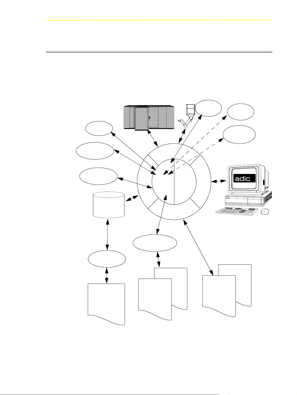
Overview of AMU
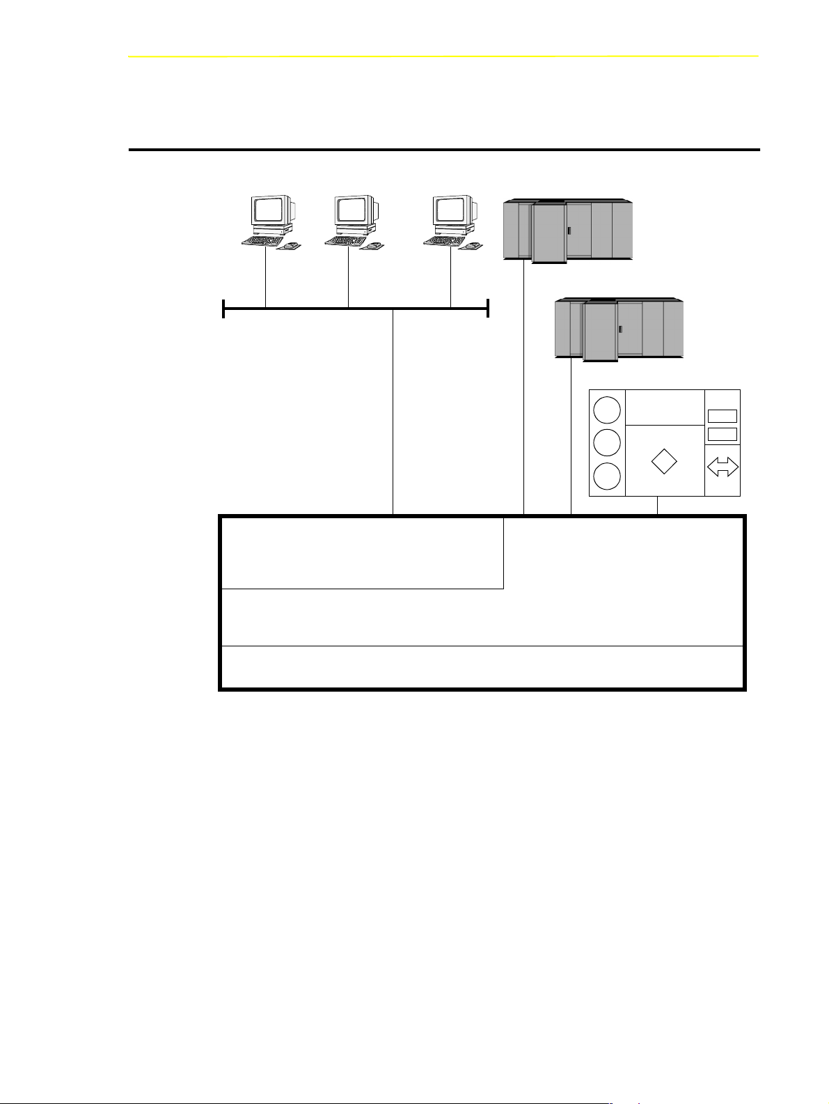
2 Overview of AMU
AMU
DAS Clients
TCP/IP
Distributed AML Server
DAS
Mainframe
AML System
AML Management Unit
AMU
OS/2
Fig. 2-1: AMU in a Multi-Host Environment
102 DOC E00 024-B Reference Guide Page 2 - 1
Page 16

The AMU
• is the main processor of the AML Mixed-Media Library
• (for each AML one AMU is required)
• is the central interface of the unmanned AML system
• conducts the configuration service for hardware related AML functions
• can be connected to several hosts
• manages a database (SQL database DB/2 for OS/2) for
- assignment of volsers to compartments
- cleaning media
- groups for rewritable media (scratch pools)
• is the hardware on which the following programmes are running
- AML Management Software (AMU) and
- Distributed AML Server (DAS) (optional for connection of Distributed
AML Clients)
• can be connected to a second AML to enhance the failure safety (dual AMU)
With the appropriate configuration, AMU can control various kinematics:
•AML/2
•AML/E
•AML/J
• Scalar 1000
Information
In den following chapters the AML Management Unit (AMU) described.
Information on DAS is found in following manuals:
• DAS Administration Guide
• DAS Interfacing Guide
Page 2 - 2 Reference Guide 102
DOC E00 024-B
Page 17

Tasks of AMU
2.1 Tasks of AMU
2.1.1 Command Management
AMU accepts commands incoming via various interfaces:
• host interfaces
• graphic operating console on AMU processor (☞ Page 4-1)
The commands are either processed immediately and acknowledged (e.g. database
querries) or entered on a command queue according to priority. The software can
enter up to 50 commands on the command queue. All important events related to
these commands are recorded in a log file.
With AMU 3.00 can be mounted also not "Foreign Cartridges" from the I/O unit.
But the user make sure, that this compartment are still empty for the Keep
(Dismount)
2.1.2 Dismount Management
Dismounting includes:
• the unload command to the drive
• the process inside the drive preparing the unloading (e. g. rewinding on tape
drives)
• the dismounting (medium is moved to dismounting position)
• the robot command to move the medium from the drive to a new position (e.g.
home position)
These procedures take up a differing amount of time depending on the type of
drive. With the aid of the Dismount Manager these procedures can be adapted to
the different drive types, and be controlled even if there are time differences for
dismounting by the robots.(☞ “Drive” on page 5 - 22)
For DLT-Low-Profile-drives operation is precondition the Drive Control Interface
(DCI). This direct drive interface to the AMU prevent not necessary dismount
actions and a drive controlled cleaning.
102 DOC E00 024-B Reference Guide Page 2 - 3
Page 18

2.1.3 Clean Management
In an AML some drives may require cleaning. The following modes are
differentiated:
• drive is cyclically cleansed manually
• drive is cyclically cleansed automatically using a cleaning medium
• drive is cleansed manually as needed
• drive is cleansed automatically as needed
To determine the cleaning mode required for your drive turn to the drive´s
documentation or ask the drive´s manufacturer.
Clean Management supports cyclical automatic cleaning and automatic cleaning as
needed.
Cyclical cleaning is based on a count of the mount procedures.
Tasks of AMU
Information
If your application should support cleaning of drives as needed or cleaning
based on the read and write procedures of the drive, use this version
preferrably.
The cleaning cycle for the drive in the archive is individually adjusted for each
drive. When cleaning is required, the Clean Manager selects a cleaning medium
from the cleanpool.
The cleanpool is the amount of cleaning media of a certain type, and each medium
in the cleanpool has a barcode label. Parameters required are assigned the
cleanpool, such as maximum number of uses of the medium and minimum number
of cleaning media required.
The cleanpool is filled by special insert commands for cleaning media. The
application receives a message when the number of available cleaning media drops
below the minium amount. The eject command for cleaning media is used to eject
exhausted cleaning media.
In addition to this cyclical cleaning the application also offers a command for
immediate cleaning of a drive.
DLT-LowProfile drives sends the clean request via DCI to the AMU, so that the
Clean Manager clean the drive only in the right situation.
Page 2 - 4 Reference Guide 102
DOC E00 024-B
Page 19

Tasks of AMU
2.1.4 Import/Export Management
In AML systems ranges and units are defined for import and export of media.
AMU differentiates these according to the type of I/O unit:
• import and export without stopping the robot
• import and export with stopping the robot (I/O unit/D -HICAP AML/J)
and according to the type of host connection for import and export:
• host-controlled
• AMU-controlled
Host-Controlled
The operator request the I/O unit by pressing a push-button and thereby makes it
unavailable for the system (I/O unit cannot be used by the robot while operator is
active).
After release by the system, the operator opens the I/O unit and removes the media
from the I/O unit as well as puts other media into the I/O unit.
When the I/O unit has been closed it is automatically made available to the system.
Robot activities designed to check the changes made, are started by commands
send by the HOST software (HACC/MVS).
AMU-Controlled
The operator request the I/O unit by pressing a push-button and thereby makes it
unavailable for the system (I/O unit cannot be used by the robot while operator is
active).
After release by the system, the operator opens the I/O unit and removes the media
from the I/O unit as well as puts other media into the I/O unit.
When the I/O unit has been closed it is automatically made available to the system.
AMU starts checking the open ranges. Movement of media (filing in a storage
area) is triggered by a host command.
102 DOC E00 024-B Reference Guide Page 2 - 5
Page 20

Foreign Mount
In the I/O unit a range for direct mount can be reserved (without insertion into
archive shelves or towers). The media stored therein do not require a barcode label
for identification. The assignment is made via the compartments and virtual volsers
(e.g.*FR001).
2.1.5 Database
The information on compartments in the archive and the media in the archive is
save in a relational database. Such information includes
• serial number of the medium represented by a barcode (VOLSER),
• kind of coordinate (CTYPE), e.g., can a cleaning or data medium be stored on
this coordinate,
• qualities of the coordinate (CATTR),
- is it occupied or empty,
- has the Volser just been mounted on a drive,
• how often has it been used (USECOUNT),
• which robots have access right (COWNER),
• type of media that can be stored on this coordinate (MEDIA),
• backup status in case a Dual-AMU is used (BUDSTATE),
• time of the last change (TIMESTMP),
• status of the medium, e.e. scratch (VTYPE),
• number of uses of the medium/drive for drive cleaning (COUNTER).
Tasks of AMU
The AML database consists of three tables:
• COORDINATES (compartments in the archive),
• SCOORDINATES (drives and I/O unit) and
• POOL (scratch and cleaning media).
The database is automatically accessed with every host command.
Page 2 - 6 Reference Guide 102
DOC E00 024-B
Page 21

Tasks of AMU
Archive Organization
The table COORDINATES can be configurated for various applications:
• Hierarchical Archive Organization
Volser are assigned to coordinates in rising order. To allow for this, ranges
(Volser ranges) are defined when the database is set up, and the data records are
preassigned to these.
A Volser can be stored in the system only if it is within a Volser range and
therefore has a home coordinate (home position).
Identification is made automatically with the aid of the barcode label on the
storage medium.
• Dynamic Archive Organization
no fixed assignment of coordinates and Volsers upon setup of the database.
Volser are filed in random order in the archive (this type of organization is
recommended if the Vosers in the archive change frequently).
If a Volser as yet unknown to the system is to be inserted, it is automatically
inserted at the first vacant compartment in the dynamic range. This
compartment remains the home position of the Volser until it is ejected from the
system with the “Eject Total” option.
• Dynamic Archive Organization with HACC/MVS
The host software HACC/MVS runs its own archive.When a new Volser is
inserted into the system, the target coordinate (new home position) is assigned
by HACC/MVS.
This system also differentiates temporary and total ejection.
In one archive several organization principles may be used in combination (e.g. 1st
range dynamic, 2nd range hierarchical).
102 DOC E00 024-B Reference Guide Page 2 - 7
Page 22
2.1.6 Data Safety
The AMU plays a key roll in the connection of host systems and robot system.
An AMU failure leads to a standstill of the entire robot system.
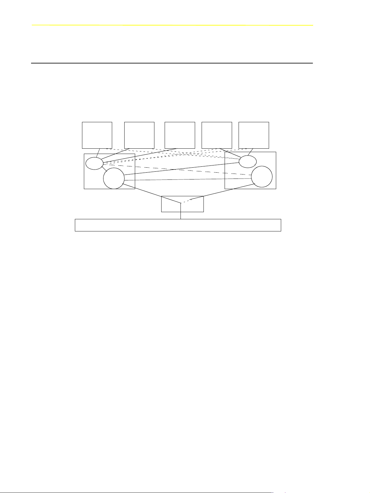
Dual AMU
Tasks of AMU
Host 1 Host 4Host 3Host 2
RTE
AMU
AMU A AMU B
ADS
Robot Control System
Fig. 2-2: Functional Principle Dual AMU
Host 5
RTE
AMU
Dual AMUs are two identical computers for control of ADIC archives (AML/2 and
AML/E). The AMU computers are connected to the control units of the archives by
means of Automatic Data Switch (ADS) via an RS232C connection.
The ADS is a remote-controlled switch creating the connection between AMU PC
and control components. If one AMU fails, a command shifts the switch and
processing is resumed by the second AMU.
The two AMU computers are linked by an RS232 interface or a LAN. This
connection is used to
• synchronize the databases,
• transfer commands (routing function),
• transfer configuration data (command controlled).
For the host systems the Dual AMU is a single system (not two separate
computers). The information on which of the two AMU computers is currently
holding the connection to the robot control unit, is irrelevant for the function. Both
AMU computers can receive host commands.
The commands are automatically sent to the active AMU and the robot control
unit.
Page 2 - 8 Reference Guide 102
DOC E00 024-B
Page 23

Tasks of AMU
If the AMU (AML Management Unit) fails, the router (RTE) continues to run. In
the example shown in figure 2-2 there is no change in Host-AMU-communication
when AMU fails on AMU A. Only the ADS is switched by the switch command
and the router of AMU A sends the host commands to the AMU of AMU B. If
AMU A fails entirely, the router is likewise no longer available. In this situation the
host-AMU-communication must be changed. Since host 3 in the above example is
not connected to AMU B, it would not be able to control the AML system if AMU
A fails entirely.
Database Backup
Independent of the Dual AMU, a constant, current backup of the database can be
created: the database backup
(☞
You can switch the database backup function on or off with an entry in the
configuration file AMUCONF.INI (☞ “Process Configuration” from page 4-30).
Process Configuration
Database Backup
or
).
By means of an entry in the configuration file you can determine where backup and
journal files will be saved.☞
You can write these files
• to a second physical harddisk in the AMU PC,
• via the IBM-LAN-Requester to a LAN server (accessory). This would also
provide protection from possible disk crashes.
Information
If a LAN server is used, the function of the network must be guaranteed. A
functional defect in the connection to the LAN server can cause a failure of
AMU.
Also, after interruption of the connection to a LAN server (e.g. after
shutdown of the LAN server) manual intervention for sign-on to the LAN
server is required.
The database backup starts once per day: when AMU is idling (“Idle Time”) at a
programmable time.
The backup runs as an independent task in the background, that is while the system
operates.All data records in the database are written to an ASCII file in their
entirity (complete backup). Additionally, all current changes are protocolled in
separate files (journal files).
102 DOC E00 024-B Reference Guide Page 2 - 9
Page 24

Tasks of AMU
Since the database backup is created outside the database system, it will remain
available for restoration even if the database manager fails.
You can completely restore a database. To do that the following is required
• backup file,
• corresponding journal file and
on the AMU operating console in menu
(
☞Page 4-41).
During the restoration, the backup and journal files are checked for integrity.
2.1.7 Log Function
The activities of the archive software on the AMU computer (AMU, DAS) are
recorded in the AMU log.
For each day (beginning at 0.00 hours) a new log file is opened. The log file is
written into a defined directory (preset to: C:\AMU\LOGS-TRC). If the available
storage capacity drops below a defined value
(preset to:40 MB), the oldest log files are deleted.
The log files are saved in ASCII format and can be read with any ASCII viewer.
Information
Log files up to version 2.40J are saved in binary format and must be converted
for reading. You can detect this on the 3 letters LOG in the filename for
binary, instead of LO for the ASCII-File.
Service
the command
Restore
2.1.8 Disaster Recovery Support
After a failure of the entire data processing center (host and disk storage), some
media are immediately required from the archive, to be able to continue operating
with a spare data processing center (Disaster Recovery). Since the host and
therefore the software for control of the AML system is not longer available in this
case, the export is controlled by AMU
(☞ “Ejection Procedure for Disaster Recovery” from page 7-9).
Page 2 - 10 Reference Guide 102
DOC E00 024-B
Page 25

Tasks of AMU
2.1.9 Host Connections
Host connection is made either
• directly by AMU (mainframes) or
• by DAS (Distributed AML Clients).
AMU as Server
In environments with several hosts, AMU operates as a server.
It takes over the entire coordination, since several host computers can access the
AML system in parallel.
To enhance fail safety of the system, two AMU computers can be connected to one
AML system (dual AMU).
The corresponding host software components communicate with AMU via various
connections.
Selection and Number of Connections
The connection types available for the respective host type can be extracted from
the table below and the diagram in this chapter.
The number of possible parallel host connections to AMU is limited only by the
AMU hardware. If the version does not provide what is required, select the next
higher hardware version.
The AMU hardware currently employed can be used for systems with up to three
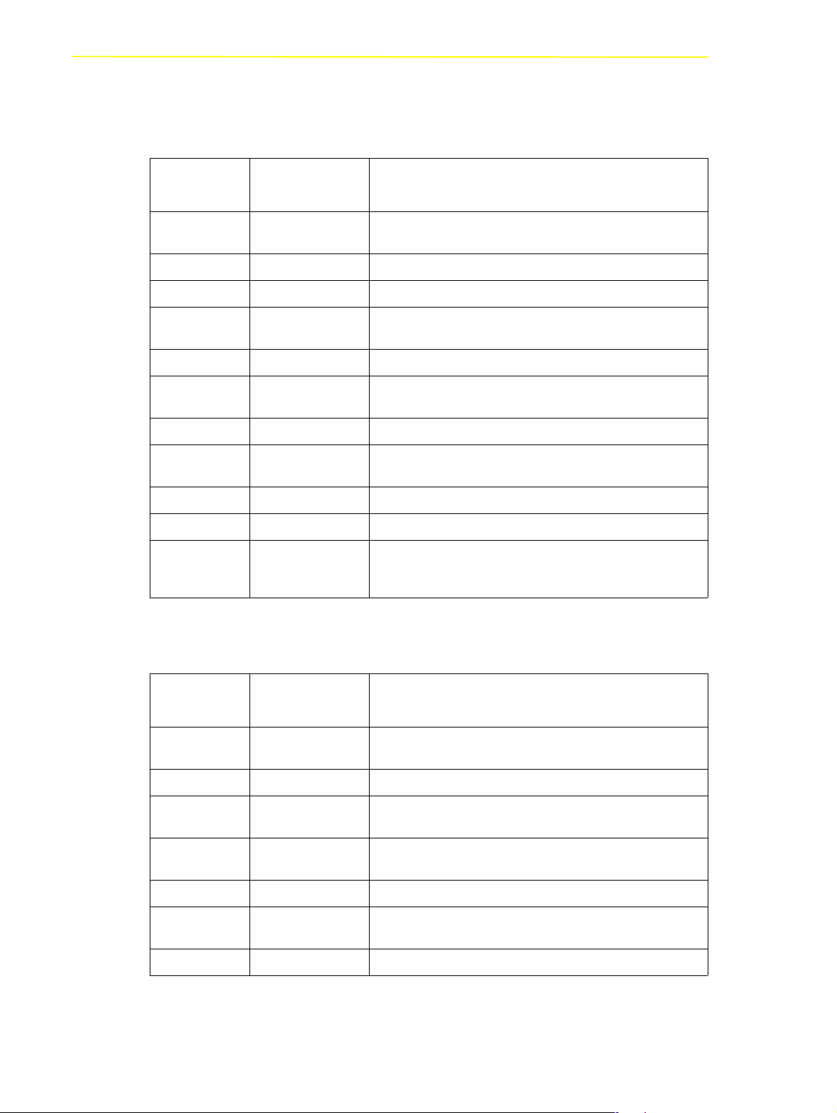
physically differing host connections (e.g. Token Ring, Ethernet and 3270Connection).
Host Host Software
IBM - MVS HACC/MVS
IBM - VM/VSE HACC/VM/VSE
Siemens BS2000 ROBAR (BS2000)
IBM - AS400 LMS (M&T Consults)
Tandem TwinATL
UNIX HACC/DAS
DEC HACC/Open VMS
102 DOC E00 024-B Reference Guide Page 2 - 11
Page 26

Tasks of AMU
Limitations
In an environment with several hosts the following limitations apply
• 1 coaxial connection (EXCP / LU 2) per AMU,
• 1 Token Ring connection with n x LU 6.2- and 1 coaxial connection in parallel,
• simultaneous connection of HACC/MVS and HACC/VM:
- HACC/MVS via LU 6.2,
- HACC/VM via EXCP/LU 2,
• always additionally possible is: TCP/IP via Ethernet,
• always additionally possible is: AML via RS-232-C.
Connecting Options
The following chart provides an overview of the various connecting options.
Page 2 - 12 Reference Guide 102
DOC E00 024-B
Page 27
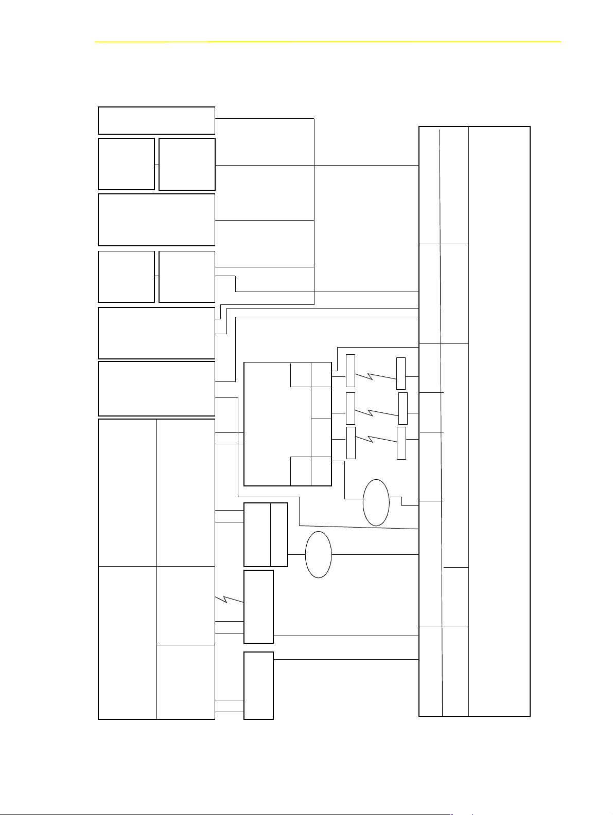
Tasks of AMU
Vo l S e r v
DAS
Clients
VA X
BS2000
Tande m
Tandem
AS/400
OS/400
HACC/MVS
VMS
Trob-
HACC/
HACC/
Guardian
Guardia
Restore
Backup/
DAS
MAN
(SINIX)
ROBAR
n
Kernel
NonStop-
HACC/
SNA
(VTAM)
OS/400
CHANNELCHANNEL
(V24)
RS-232-C
3745
LAN
Ring, ISDN)
(Ethernet, Token
LAN-Adapter
AML TCP/IP
RS-232-C
(In-
X.25
X.25
SDLC
house)
Modem
X.25
(64K)
Modem
(19200K)
ISDN
Modem
SDLC
AMU
LU 6.2
Ring
Toke n
NPSI
Modem
X.25
ISDN
Modem
NCP
SDLC
Modem
TR
NTRI
TR
3174/3274
REMOTE
Ring
Tok en
TR-Adapter
LU 2
SNA
(VTAM)
3174/3274
Koax
(LU 2)
HACC/MVS
HACC/VM/VSE
Non-SNA
102 DOC E00 024-B Reference Guide Page 2 - 13
3174/3274
Koax
(EXCP)
OS/2, CM/2, DB 2/2
EHLLAPI
3270 Connection
Page 28

2.1.10 Access Rights
Access rights to the functions of the AMU software are assigned to different levels.
Access to AMU Operating Console
Three user groups are differentiated:
Tasks of AMU
supervisor
system technician with full access right to the
system,
administrator
system administrator and task preparation have
access to configuration of the system,
operator
system operator, user of the system, without access to
configuration.
Database Access
Authorization for database access is automatically made with the user
identification “AMUADMIN”.
Page 2 - 14 Reference Guide 102
DOC E00 024-B
Page 29
AMU Processes
2.2 AMU Processes
The software consists of individual programs (processes) running in parallel
(multi-tasking). Each process accomplishes a specific task. Additionally, there are
various service utilities.
DIM
CLM
BUD
DB 2/2
HOC
KrnL
ARC
ART
CFG-Server
KnP
RTE
CON
RFM
PMMaint
ARCBACK
AMUCONF
AMUCONST
Logs
Traces
DB Backup
Fig. 2-3: AMU Processes
102 DOC E00 024-B Reference Guide Page 2 - 15
Page 30
Functions of Processes
AMU Processes
Abbrevia-
tion
Arc Archive manages and protocols (journaling) archive catalog; SQL
ArcBack Archive-Backup short-term, writes backup file
ART Alerter wirtes logs and traces
BUD Backup Daemon background process for control of data transfer between dual
Clm Clean Manager monitors cleaning of drives
Con AMU Operator
Dim Dismount Manager monitors drive cleaning
Hoc Host and other
KRN-L (Kernel-logical central logic, converts host commands to control commands
KNP Kernel-physical processing for robot (compute coordinates)
RTE Router set up routing table,
Name Explanation
database
AMUs
operator surface for application, installation and maintenance
Console
process controlling the communication to all external systems
Communication
(e.g. HACC/MVS, robot control unit of AML/2)
passes on host commands from passive AMU computer to
active AMU computer and back
Service Programs
Abbrevia-
tion
INI2CONF AMUINI Converter converts AMUINI.IN file in AMU version 2.00 to
JustUtil JustUtility editor for teach point files for AML/2 and AML/E
Log2Asc Log to ASCII converts binary coded log file from AMU version 2.4 and
PmMaint PMAC
patini patini allows to edit binary configuration files
RFM Rho File manager file transer to rho control when Kernel, HOC and ARC (incl.
showini showini displays binary-coded configuration file in ASCII format
Page 2 - 16 Reference Guide 102
Name Explanation
AMUCONF.INI
earlier to ASCII file
microcode download and diagnosys program for AML/J control
Maintenance
unit (PMAC)
DB 2/2) have been stopped
DOC E00 024-B
Page 31

AMU System Requirements
2.3 AMU System Requirements
2.3.1 Hardware
Processor
Main storare
Harddisk
Graphics adapter
Input device
2.3.2 Software
Operating system
Data Base Manager
min. Intel Pentium 120 MHz
min. 32 MB RAM (64 MB recommended, required
for systems with 2 or more hosts)
min. one harddisk with 850 MB (2 harddisks
recommended)
XGA min. resolution 1024 x 768
keyboard and mouse or trackball
OS/2 3.0 (Warp)
MPTS Fixpack WR08610
IBM DATABASE 2 (Single User) (Version 2.1 or
higher)
Communication
102 DOC E00 024-B Reference Guide Page 2 - 17
optional, depending on host connection
IBM Communications Manager CM/2 2.1 or higher
IBM TCP/IP 3.0 (part of Warp Connect)
Page 32

2.3.3 Compatibility
This AMU version requires the following host and control software versions:
AMU System Requirements
Software Version Comments
AML/2 control unit 2.20D or higher Standard gripper
2.30D or higher Parallel gripper
AML/E control unit 2.20D or higher Standard gripper
2.30C or higher Parallel gripper
AML/J control unit 2.40D or higher
Scalar 1000 control unit Microcode 1.01 or
higher
DAS 1.2 UNIX
3.01 or higher OS/2
ROBAR V2.5 or higher V3.02
HACC/OS400 V2.2 or higher
HACC/MVS 3.0 PTF ZY30015 older version does
TwinATL S0308D20 or higher
HACC/VM 1.4.2
Driver SCSI-Util
(version 1.02 or
higher) required for
it
recommended
not support the
DUAL- and
CLEAN function
Page 2 - 18 Reference Guide 102
DOC E00 024-B
Page 33

For Your Safety
3 For Your Safety
Information
In addition to the safety instructions in this chapter, local and special safety
instructions relating to this kind of product apply.
Avoid hazard during maintenance and operation of the system by
• safety-conscious behaviour,
• careful action.
ATTENTION!
Knowledge of and adherence to these instructions are indispensible preconditions for safe maintenance of the AML system.
102 DOC E00 024-B Reference Guide Page 3 - 1
Page 34

3.1 Hazard Alert Messages
We classify the hazards in several categories. The following table shows the relation of symbols, signal words, the actual hazard, and its possible consequences.
Hazard Alert Messages
Symbol
Damage
to...
People
Property
Signal Word Definition Consequences
DANGER!
imminently hazardous
death or serious
injury (maiming)
situation
WA R NI N G !
potentially
hazardous
possibly death or
serious injury
situation
CAUTION!
ATTEN-
TION!
less hazardous
situation
potentially damaging
situation
possibly minor or
moderate injury
possibly damaging
to:
• the product
• its environment
Information
tips for users and
other important/
useful information and notes
No hazardous or
damaging consequences for people
or property
Page 3 - 2 Reference Guide 102
DOC E00 024-B
Page 35

Further Symbols
3.2 Further Symbols
The table below lists all symbols used in this manual and explains their meanings.
Symbol
Damage
to...
People
People
Signal Word Definition Consequences
WA R NI N G !
Hazardous volt-
age!
CAUTION!
Laser -
radiation!
Do not look
into the laser
beam!
Potentially
hazardous
situation
Replaces the
pictorial
when the source
of hazard is
electric energy.
Less hazardous
situation.
Laser radiation
Possibly death or
serious injury.
After an EMERGENCY STOP
and also after
power-down of the
main switch, voltage may still be
present at locations identified by
this pictorial.
Hazard of fatal
electric shock!
Possibly minor or
moderate injury.
Laser radiation is
emitted upon
opening.
Calls attention
to the address of
-
102 DOC E00 024-B Reference Guide Page 3 - 3
your service
contact.
No hazardous or
damaging
consequences for
people or
property
Page 36

3.3 Scope of Application
These instructions apply to the AML system.
Further safety regulations for the components used in the system are not invalidated by the present instructions.
Information
The documents of component suppliers are part of this AML documentation.
Scope of Application
Page 3 - 4 Reference Guide 102
DOC E00 024-B
Page 37

Operating Console
4 Operating Console
Input at the operating console of the AMU have the same access priority to the system as host commands.
ATTENTION!
Especially when using the commands
conflicts with host commands.
If in doubt, restart the AMU after using any of these commands.
After change of the configuration restart of AMU (AMU and DAS) is mandatory.
Input at the AMU must be restricted to the following situations:
• host communication failure
• robot failure (manual update of the archive catalog after manual interventions
(☞ Operator Guide)
• during installation
• during maintenance
Information
All non-executable commands or options are displayed with a shadow.
Put, Get, Look
, and
Teach
, be sure to prevent
4.1 Application
Design and application conform to the SAA standard.
It it operated with
• the keyboard
• the mouse
Further information is found in the OS/2 manuals.
102 DOC E00 024-B Reference Guide Page 4 - 1
Page 38

4.1.1 Design of the Menu Bar
System menu field Title bar Menu bar Symbol field Max. size field
AMU Release
AMU Status *
BUD - Active
*
BUD - Passive
BUD - Active: Partner lost
Shutdown in Progress
Fig. 4-1: Design of the AMU Menu Bar
- AMU, currently controlling the AML
- AMU inactive, router sends commands to active AMU
- no connection to dual AMU
- command Shutdown has been processed
Application
Information
In the active window the title bar´s background is dark; in inactive windows
the title bar´s background is light.
The following functions are the same in all windows:
Button Function
Cancels the current function and closes the window.
Opens online help.
System menu field
Fig. 4-2: System Menu Field of AMU
Page 4 - 2 Reference Guide 102
DOC E00 024-B
Page 39

Application
4.1.2 Selecting a Command
With the mouse
a) Move the mouse pointer to the desired menu in the menu bar.
b) Click on the menu; the menu opens.
c) Click on the command in the menu; the command window opens.
With the keyboard
a) Press the <ALT> key and the underlined letter in the menu bar. The menu
opens.
b) Now press the underlined letter in the menu to select the command.
With a command code
If a key or a combination of keys is specified following the command you can
directly select the command with it.
102 DOC E00 024-B Reference Guide Page 4 - 3
Page 40

4.1.3 Altering a Window´s Size
Resizable windows have a frame all around (e. g. Trace window).
a) Move the mouse to any corner of the active window.
The mouse pointer changes into a double arrow.
b) Press the mouse button and pull the window to the desired size while keeping
the mouse button pressed.
4.1.4 Moving a Window
a) Move the mouse pointer onto the title bar.
b) Move the window while keeping the mouse button pressed.
Application
4.1.5 Closing a Window
a) Close the window by a double click on the system menu field.
Page 4 - 4 Reference Guide 102
DOC E00 024-B
Page 41

Overview of Menus
4.2 Overview of Menus
All commands of the AMU operating console are explained here:
Fig. 4-3: Overview of Menus of AMU
Information
When dual AMU is used, only the command Switch can be processed by the passive AMU (even the command View Archive Catalog Management is not allowed
for the passive AMU). Enter all commands at the active AMU.
102 DOC E00 024-B Reference Guide Page 4 - 5
Page 42

4.3 Menu Shutdown
Fig. 4-4: Menu “Shutdown”
Command Field Explanation
Menu Shutdown
Shutdown AMU
Prepare shutdown of the AML system.
Fig. 4-5: Window “SHUTDOWN OF AMU”
ATTENTION!
Before shutting down, interrupt the communication with the host computer (e. g. with HOLD
1,1).
Short-cut: function key F12
Yes
The current command will still be processed.
After that, all modules of the AMU will be
terminated and the database will be closed.
Information
Shutting down of the system
☞ Operator Guide.
No
Page 4 - 6 Reference Guide 102
Return to the program, no shut-down.
DOC E00 024-B
Page 43

Menu Shutdown
Command Field Explanation
Shutdown complete (with OS/
2)
Prepare shutdown of the AML system (like
AML-System
), thereafter terminate all processes running under
Shutdown only
OS/2 and perform OS/2 system shutdown.
Fig. 4-6: Window “TOTAL SYSTEM SHUTDOWN”
ATTENT I ON!
Before shutting down, interrupt the communication with the host computer
(e.g. with HOLD 1,1).
102 DOC E00 024-B Reference Guide Page 4 - 7
Page 44

4.4 Menu Edit
Fig. 4-7: Menu “Edit”
Command Explanation
Menu Edit
Cut
Copy
Paste
Cut the marked object and file it in the intermediate storage
(computer main storage).
Short-cut: press keys <Shift>+<Del>
Copy marked object to the intermediate storage.
Short-cut: press keys <Control>+<Ins>
Insert object from intermediate storage at the current cursor
position.
Short-cut: press keys <Shift>+<Ins>
Page 4 - 8 Reference Guide 102
DOC E00 024-B
Page 45

Menu View
4.5 Menu View
Fig. 4-8: Menu “View”
Calls up information in various windows.
4.5.1 Archive
Allows to check and change archive catalog entries for compartments.
After input of a Volser or selection of a coordinate, all corresponding information
in the database is displayed. If a Volser occurs more than once, only the first entry
in the database is shown.
Fig. 4-9: Window “Archive Catalog Management”
102 DOC E00 024-B Reference Guide Page 4 - 9
Page 46

.
Field Explanation
Menu View
Coordinate
Volser
Logic coordinates of the medium in the archive.
Information
One optical disk occupies 2 logic coordinates,
one for each side.
The digits of the coordinates indicate the following:
TT
NNSSRR
P
P
Compartment
Row
Segment
Device No.
Device Type
List of device types (☞Page 10-10)
With the aid of the four selection windows, select the desired
coordinate for display of the data record of a coordinate.
Serial number of the medium, represented by a barcode, also
referred to as VSN.
Volsers are alphanumeric and between 1 and max. 16 characters long.
Following Volsers are not allowed:
• 0000000000000000
• CLEAN
Enter the Volser on the field to search the medium in the database.
Page 4 - 10 Reference Guide 102
DOC E00 024-B
Page 47

Menu View
Field Explanation
Medium
Attribute
Type of medium for monitoring of assignment of archive drive.
Medium cannot be changed in the Archive Catalog Management.
Information
Not all media types are generally differentiated
even if they have the same kind of housing.
List of media types (QVW)
Status of medium (the characters in brackets are the variables
for the database)
Occupied
Ejected
(O) Compartment occupied by medium
(E) Compartment is empty, medium has been
ejected
Mounted
(M) Compartment is empty, medium is mounted
in drive
Initial
(I) Not used
In Jukebox
Reverse Side
Mounted
Empty
Undefined
Temp Away
Temp Here
(J) Compartment is empty,
(R)
(Y) Campartment is empty
(U) Undefined (special attribute for HACC/
(T) On AML/2 twin-robot system the compart-
(A) Occupied compartment in the problem box
Optical Disk is in the jukebox
Compartment is empty,
Optical Disk is mounted in drive (reverse
side)
MVS)
ment in the storage tower is temporarily
occupied for transfer to the other robot
102 DOC E00 024-B Reference Guide Page 4 - 11
Page 48

Field Explanation
Menu View
Type
Type of compartment in the archive
Storage
(S)
• Archive compartment for
- hierarchically defined Volser ranges
- dynamically defined Volser ranges, on
HACC/MVS only
- no cleaning medium compartment
Clean
(N) Cleaning media compartment
AMUDynamic
(A)
(not on HACC/MVS) archive compartment
for dynamic insert and transit
Type of compartment in the I/O unit
Foreign
Problem
(F) Foreign media compartment
(P) Compartment in the problem box
(I/O unit)
HACCDynamic
AMUDynamic
(D)
(A)
not used
Archive compartment for dynamic use of the
I/O unit
VType
Use Count
Crash Count
Volser type of storage media
Undefined
•
(U): Undefined (neither scratch medium nor
scratch media management on AMU)
Scratch
•
(S): Scratch medium
VType cannot be changed in the Archive Catalog Management.
Information
The value of this filed can be changed in the
menu Admin with Scratch Pool or with a host
command.
Number of accesses to compartment.
Use Count cannot be changed in the Archive Catalog Management.
Not used
Page 4 - 12 Reference Guide 102
DOC E00 024-B
Page 49

Menu View
Field Explanation
Robot Access
Status
Message
Access right of robot to compartment
Reply of AMU with message number (☞Page 8-1)
after execution of a command has failed
(e.g. Not found: RC = 1032)
Commands
Command Explanation
View
Coordinate
View Next
Display the archive catalog entry for the logic archive coordinate entered.
Display the archive catalog entry of the next coordinate of the
component. When the last coordinate has been reached no
scrolling occurs.
View Prev
Display the archive catalog entry for the previous coordinate
of the component. When the first coordinate has been reached
no scrolling occurs.
View Volser
Display the archive catalog entry for the volser entered.
Update
Information
This command can only be used after logon as
administrator or supervisor.
Update the archive catalog entry for the archive coordinate.
ATTENT I ON!
The existing entry in the archive catalog will be
overwritten. Wrong entries can lead to discrepancies between the archive and the HACC/
MVS archive catalog.
102 DOC E00 024-B Reference Guide Page 4 - 13
Page 50

4.5.2 Trace
Online or offline protocol of internal processes of the AMU Software (AMU and
DAS). The records can be selected by levels (AMU processes).
Information
The selection of trace can slow down the processing!
Change the selection only after consulting ADIC Technical Support.
Standard selection: no traces.
ATTENTION!
The memory for the current trace is limited. When failures occur file the trace
as soon as possible.
Menu View
Fig. 4-10: Window “Trace”
Field/Com-
mand
List of
TraceID’s
Page 4 - 14 Reference Guide 102
Trace levels can be selected with the <SPACE> bar or the
mouse. List of all trace ID’s (☞Page 10-4)
Explanation
DOC E00 024-B
Page 51

Menu View
Trace:
Online
✔
The running trace is additionally displayed on-screen with
•time
• trace ID (e.g. 03100 means trace KRN 1)
• trace entry (depending on type of trace)
Time
Trace ID Trace Text
OFF
ON
Select All
Unselect All
Filename
Save
/
Fig. 4-11: Window “Trace” (Online)
Switch trace off.
Write current traces into the main storage (1 MB reserved).
When the storage is full the oldest entry is overwritten.
All entries in the Online trace window are marked or the mark
is removed
Path and filename of trace in binary format, after processing of
the command
Save
Save protocolled traces in a file with the binary code name
preset in field Filename
Select this command immediately after a problem has
occurred to ensure the trace information is not lost.
After formatting, this file can be printed (☞
Format
) with the
OS/2 Print command.
102 DOC E00 024-B Reference Guide Page 4 - 15
Page 52

Menu View
Format
Converts a trace file stored with
Save
into a printable format
(ASCII).
Fig. 4-12: Window “Format Trace Files”
Target filename with path
(e.g.
a:\name
c:\amu\logs-trc\name
or
).
Start formatting.
The execution will be confirmed by display of the message
formatted 100%
“
”.
Infile
Outfile
Start
Formatting
ormatted
f
Path and name of binary-coded trace file for
conversion to ASCII format
(default: C:\AMU\LOGS-TRC)
Path and name of ASCII trace file after conversion to ASCII Format
Start formatting process
Select this command after your have entered
the filenames in the fields
Infile
and
Outfile
.
Status display for formatting; when its
shows
100%
, formatting is complete
Page 4 - 16 Reference Guide 102
DOC E00 024-B
Page 53

Menu View
4.5.3 Log
The alerter protocols all messages (even when the window AMU-Log Control
Center is not open).
Examples:
• host computer commands
• execution of host commmands
• messages to the host computer
• user interventions
• error messages
Log files begin daily at 0.00 hours. If the available storage on the harddisk drops
below the value set in the configuration file ARTCFG.DAT (default 40 MB), the
oldest log files are deleted (☞ Page 5-62).
Information
Log files cannot cover several days! There is only one log file for each day.
Information
The first line in each log file contains the version number of the current AMU.
Date
Fig. 4-13: Window “AMU Log”
102 DOC E00 024-B Reference Guide Page 4 - 17
Time
Message number
Command sequence Number
Message text
Page 54

Menu View
Field/com-
mand
Log archive
Explanation
Open a window for selection of stored log files with automatic
display in the OS/2 editor EPM
The log filename comprises
lo <Day><Month>.001
List of all files saved in the
defined log directory
Status information
(e.g. number or log files
or selection)
Status information
(e.g. pathname or
instruction to open file)
Fig. 4-14: Window “View Log Files”
View
Copy the selected file into a temporary file
(logview.txt). This file is displayed in the
OS/2 editor EPM and can be processed as
desired.
Page 4 - 18 Reference Guide 102
DOC E00 024-B
Page 55

Menu View
Fontsize
Select font type, size and style for the contents in window
Log
Fig. 4-15: Window “Log Font Dialog”
Name
Size
Style
Selection window for all installed font types
Selection window for font size in pt
Selection window for font styles (available
for some font types only)
AMU
Display
Printer
Outline
Underline
Strikeout
Sample
Ok
Selection of display fonts, do not change settings
Not used
Contour font
Underlined font
Strikeout font
Display sample of selected font
Activate slection for currently running AMU
Log. When the AMU Log window is opened
again, the default font is again displayed
(System VIO).
102 DOC E00 024-B Reference Guide Page 4 - 19
Page 56

4.6 Menu Operations
Fig. 4-16: Menu “Operations”
4.6.1 Login/Logoff (Operator)
Menu Operations
Command Field Explanation
Login
(Operator) /
Logoff
If you wish to use the locked function in menu Operator, you
must log on as operator, administrator or supervisor
To protect the system from unauthorized use, logoff when you
have completed operations
Fig. 4-17: Window “Operator Login”
Password Field for input of the operator password. Request this
password from your system administrator
Ok Perform login.
Page 4 - 20 Reference Guide 102
DOC E00 024-B
Page 57

Menu Operations
4.6.2 Manual Operation
Precondition: ”MANUAL” operating mode
Manual execution of the host commands
Mount
(mount medium) and
Eject
(eject
medium) by the operator. This operating mode is designed exclusively for AML/2
with active Quadro towers.
Information
AML/2 twin systems cannot run automatically and manually at the same
time.
Step 1 On AML/2 switch the key switch on the operating panel to “MANUAL”.
Step 2 On AML/2 close all guard doors of Quadro towers. The quadro tower
rotates, the robot does not move.
Step 3 On AML/2 open the guard door to a Quadro tower and remove the
medium.
Step 4 If a
Mount
command has been received, mount the medium on the drive
indicated.
Step 5 Confirm the execution of the command displayed with
OK.
Execution of the instruction is acknockledged to the host computer, and
the latter displays the next command.
The subsequent Keep is automatically acknowledged by AMU (database changed),
but is not displayed.
AML/2 only
Step 6 If a Mount command for the same drive follows, remove the medium and
put it into the I/O unit.
102 DOC E00 024-B Reference Guide Page 4 - 21
Page 58

Menu Operations
Step 7 When resuming automatic operation, first insert all media used during
MANUAL operation.
Fig. 4-18: Window “Manual Operation”
Command/
field
Command
Volser
Location
Drive
Explanation
Command from host to be executed by the Operator
Search the
Location
according to the Volser or VSN, to be able
to execute the command.
Indicates the coordinate in the archive, where the
Volser
for the
command is currently located
Unit
Segm.
Row
Number of storage tower or shelf
Number of segment in storage towers
Row in the segment (counted from bottom to
top)
Pos.
Name
Compartment (counted from left to right)
Designation (comment) defined in the configuration for the component.
Mount the medium with the
Volser
in the drive given in this
field. For EJECT commands (eject medium) this field remains
vacant.
Name
Designation (comment) defined in the configuration for the drive.
Page 4 - 22 Reference Guide 102
DOC E00 024-B
Page 59

Menu Operations
Command/
field
OK
Reject
Explanation
Select OK when the command has been executed by the operator, database update is performed, host receives positive confirmation.
Select Reject when the command will not be executed by the
operator. Database update is not performed, host receives negative confirmation.
102 DOC E00 024-B Reference Guide Page 4 - 23
Page 60

4.6.3 Disaster Recovery
Dialog window starting ejection of preselected media in case of emergency (Disaster Recovery). Thes window has two areas for independent ejection of media in
AML/2 twin-robot systems.
Menu Operations
Fig. 4-19: Window “Disaster Recovery
Command/
field
File
Window for selection of prepared files listing Volsers to be
ejected
Display all files in the directory C:\AMU\RECOVERY\ with
the filename *.DSR
(☞ “Structure of the file” from page 7-8)
Start
Stop
Status
Start the ejection of media listed in the selected file.
Stop ejection
Display the current eject status
Explanation
Page 4 - 24 Reference Guide 102
DOC E00 024-B
Page 61

Menu Operations
4.6.4 Insert Clean
Insert cleaning media.
Fig. 4-20: Window “Insert Clean Media”
ATTENTION!
All media in the insert range are treated as cleaning media. Be sure there are
not data media in the insert range while this command is executed.
Field Explanation
Pool
First select the clean pool to which the cleaning media are to be
added.
Logical
Range
Select the insert range into which you have put the cleaning
media.
102 DOC E00 024-B Reference Guide Page 4 - 25
Page 62

4.6.5 Eject Clean
Eject used cleaning media
Fig. 4-21: Window “Eject Clean Media”
ATTENTION!
Menu Operations
Do not reinsert used cleaning media. If they are used beyond the maximum
Use Count, drive failure may result.
Field Explanation
Pool
Logical
Range
Select the pool from which to eject used cleaning media.
Select the eject range into which the used cleaning media are to
be put.
Page 4 - 26 Reference Guide 102
DOC E00 024-B
Page 63

Menu Operations
4.6.6 Clean Drive
Clean drive outside automatic cleaning process.
Fig. 4-22: Window “Mount Clean Media / Clean Drive”
ATTENTION!
The servicelife of some drive types is drastically shortened by frequent cleaning. Clean drives only if it is definitely necessary.
Field Explanation
Drive
Select drive to be selected
102 DOC E00 024-B Reference Guide Page 4 - 27
Page 64

4.7 Menu Admin
Fig. 4-23: Menu “Admin”
4.7.1 Login (Administrator)
Menu Admin
Command Field Explanation
Login
(Administrator) /
Logoff
If you wish to use the locked function in menu
must log on as operator, administrator or supervisor
To protect the system from unauthorized use, logoff when you
have completed operations
Fig. 4-24: Window “Administrator Login”
Password Field for input of administrator password. Request
this password from ADIC Technical Service.
Ok Perform Login.
Admin
, you
Page 4 - 28 Reference Guide 102
DOC E00 024-B
Page 65

Menu Admin
4.7.2 Configuration
The window Graphical Configuration is used to enter all settings for system components. The settings are saved in the file AMUCONF.INI.
Fig. 4-25: Window “Graphical Configuration” example AML/J with DCI
102 DOC E00 024-B Reference Guide Page 4 - 29
Page 66

4.7.3 Process Configuration
Overview of system settings within the AMU and possibility to set the parameters
for the database backup. All these parameters are save in the file AMUCONF.INI.
Menu Admin
Fig. 4-26: Window “Process Configuration”
Range Field Explanation
General Version
Display current software release (parameter
PROC VERSION).
FillSign
Display which sign is used to complete the
variables (e.g. Volser to 16 characters) in the
command string (default: <.>, corresponds
to ASCII 0x2E)
(parameter PROC FILLSIGN).
Page 4 - 30 Reference Guide 102
DOC E00 024-B
Page 67

Menu Admin
Range Field Explanation
Kernel Load
Database
Parameter set used to create the SQL database upon execution
of the command Create Archive. Change these parameters
only if you have been specifically asked to by ADIC.
Database
Name
Display all processes started by the Kernel
(parameter PROC KRNLOAD).
KNP:
•
•
•
•
•
•
•
•
Physical Kernel Module
UPM
: User Profile Manager
ARC
: Archive Handler
HOC
: Host- und Other-Communication
BUD
: Backup Daemon
RTE
: Router
DIM
: Dismount Manager
CLM
: Clean Manager
From AMU 3.10 BUD and RTE should no
longer started with this function. Please use
therefore the batch c:\amu\AmuStart.cmd
: Name of SQL database
(parameter PROC DBNAME,
(default:
ABBA
)
Comment
CodePage
Drive
Comment on name in SQL database
(parameter PROC DBCOMMENT,
default:
ABBA/2 Management Unit Archive
)
Information on codepage of SQL database
(parameter PROC DBCODEPAGE,
default:
850
)
Drive on which the SQL database is stored
(parameter PROC DBDRIVE,
default: C)
102 DOC E00 024-B Reference Guide Page 4 - 31
Page 68

Range Field Explanation
DatabaseBackup
Path
Directory and drive storing the backup and
journal files. C:\AMU\DBBACKUP is the
standard directory. To have access to the
backup even when the AMU computer hardware is damaged (e.g. harddisk), an additional harddisk can be installed or files may
be saved via LAN to another drive
(parameter PROC DBBACKUPPATH).
ATTENTION!
Activated only after restart of
AMU!
Menu Admin
Active
FreeSpace
Start
Switch on/off backup system (parameter
PROC DBBACKUPACTIVE).
• Information on the storage management
of the backup system. If the vacant space
drops bewlo the set value in the directory
defined with
Path
, the oldest backup and
journal files are deleted (until the value
FreeSpace
for
is again reached).
Information
If the same drive is used for
AMU and DBBACKUP,the
value of 10 MB cannot be
altered!
Start time for database backup. When the
time is reached, the system waits until the
processor idles, the command execution is
then halted until the backup is complete
(parameter PROC DBBACKUPSTARTHOUR).
File Backup
Identifies the script used to execute the backup.
Script Path and Name of the backup script
Page 4 - 32 Reference Guide 102
DOC E00 024-B
Page 69

Menu Admin
Range Field Explanation
Notification’s
Retry Interval
Passwords
Set the length of time that communication retries will be
attempted between Dual AMUs.
Dual AMU
link lost
Insert clean
cartridges
Time in minutes (1 ... 120 minutes)
default is blank
Time in minutes (1 ... 120)
default is 5 minutes
Assignment of passwords for various AMU areas
Operator
Password for call-up of functions in menu
Operations (display is coded)
Administrator
Password for call-up of functions in the
menus Admin ad Operations (display is
coded)
Supervisor
Password for call-up of functions in the
menus Service, Commands, Admin and
Operations (display is coded)
Disaster Recovery
Password for call-up of the disaster recovery
procedure (display is coded). When the entry
on this field is erased, the function
Recovery
can be called up without password.
Disaster
Cfg Log Write
Switch selecting log write for configuration
activities
(parameter PROC CFGLOG).
HOC Recovery Time
Time interval after which the communication module checks all configured communication connections
(parameter PROC HOCRECOVERYTIME).
Barcode for Service
Barcode OFF
Allows to operate the system (Mount, Keep,
Eject) without reading of barcodes. For
insertion and inventory barcode reading is
always active
(parameter PROC BARCODEOFF).
102 DOC E00 024-B Reference Guide Page 4 - 33
Page 70

Range Field Explanation
Information
Select this function when scanner or vision system do not function, until they are repaired. As
long as barcode reading is inoperative, media
cannot be inserted into the archive.
Menu Admin
Page 4 - 34 Reference Guide 102
DOC E00 024-B
Page 71

Menu Admin
4.7.4 Clean Pool
Call up window for assignment of cleaning media to various groups (pools).
A clean pool is a group of cleaning media with the same qualities:
• Maximum number of cleaning cycles per medium
• Media type (e.g. 3480, 3590, DLT)
• Minimum number of cleaning media in the system
• Each individual drive can be assigned to such a pool
Fig. 4-27: Clean Pool Management
102 DOC E00 024-B Reference Guide Page 4 - 35
Page 72

Range Field Explanation
Menu Admin
Clean Pool Data Pools
Volser
Display and selection field for all groups of
cleaning media defined in the AMU database. The standard names for these pools for
hosts that do not use clean pool names are
Paa, aa being the clean pool identifier.
Display Volser in selected clean pool. The
display only indicates that the Volser has
been assigned to the pool, but does not indicate that the cleaning medium is actually
present in the archive.
The standard names for these Volsers for
host that do not use clean pool names are
CLaabb, aa being the clean pool identifier
and bb the cartridge identifier.
ATTENTION!
The volser with the standard names for cleaning media must not be used as Volsers for data
(CL0000 - CL9999). If the prefix CL is used for
data media, the parameter CLMVOLSERHEADER in PROC in the file AMUCONF.INI
can be adapted after consulting ADIC.
Pool Data
Display data for clean pool marked in Pools
Pool
Display selected clean pool
Enter the pool name on the field, to set-up a
new clean pool
Watermark
Display minimum number of cleaning media
in the archive. As guiding value take the
number of drives to be cleansed from this
pool.
Media
Page 4 - 36 Reference Guide 102
Cleaning media type; select media type used
DOC E00 024-B
Page 73

Menu Admin
Range Field Explanation
Volser Data
Max Use
Maximum number of cleaning cycles per
cleaning medium. When it has been
depleted, the medium must be ejected.
Enter the value communicated by the drive
manufacturer or cleaning medium supplier.
Number
Available
Display media currently assigned to the pool
Display cleaning media inserted in the
archive for the pool
Update Pool
Data
Delete Pool
Enters the changes made in the AMU database
Delete pool with all corresponding data from
the AMU database
Add Pool
Add new pool with selected data to the
AMU database
Data for the cleaning medium selected in Volser
Volser
Volser (VSN) of cleaning medium.
Enter the Volser (barcode number) for a new
cleaning medium on this field.
Use Count
Number of cleaning cycles sofar performed
with this medium
Update Use
Count
Delete Volser
Change the number of cleaning cylces saved
in the database for the selected Volser
Remove the Volser from the Pool (not from
the archive)
Add Volser
Refresh Pool
Data
Ok
102 DOC E00 024-B Reference Guide Page 4 - 37
Information concerning the pool are updated in the window
Terminates the dialog in Clean Pool Management
Add Volser with preset
Use Count
to the pool
Page 74

4.7.5 Scratch Pool
Call up window for assignment of storage media to different groups (pools).
A scratch pool is a group of storage media reserved by certain host applications.
Menu Admin
Fig. 4-28: Window Scratch Pool Management
Range Field Explanation
Scratch Pool
Data
Pools
Display and selection field for all defined
groups of scratch media in the AMU database
Volser
Display Volsers in selected scratch pool. The
display only indicates tha the Volser has
been assigned to the pool, but does not mean
the storage medium is actually in the
archive.
Pool Data
Page 4 - 38 Reference Guide 102
Display data of scratch pool marked in Pools
DOC E00 024-B
Page 75

Menu Admin
Range Field Explanation
Pool
High Wate
Media
Number
Available
Update Pool
Data
Delete Pool
Add Pool
Display selected pool.
Enter the pool name on the field, to set-up a
new pool.
Display minimum number of scratch media
in the archive
Storage media type, select media type used.
Display media currently assigned to selected
pool
Display storage media available in the
archive that bear the attribute scratch and
belong to the pool
Enters changes made in the AMU database
Delete pool with all corresponding data from
the AMU database
Add new pool with selected data to the
AMU database
Volser Data
Refresh Pool
Data
Ok
Data of the storage medium selected with Volser
Volser
Volser (VSN) of the storage medium.
Enter the Volser (barcode number) for a new
storage medium on this field. The medium is
assigned to the marked pool.
Scratch
Display medium attribute scratch.
Information
This is a Read Only field.
Delete Volser
Delete Volser from the pool (not from the
archive)
Add Volser
Add Volser to the pool
Pool data is refreshed in the window
Completes the dialog in Scratch Pool Management
102 DOC E00 024-B Reference Guide Page 4 - 39
Page 76

4.7.6 Create Archive
ATTENTION!
This command creates a new archive catalog.
The existing archive catalog is deleted irrevocably!
The new archive catalog is created on the basis of the configuration data.
Fig. 4-29: Window “Create a New Archive”
Menu Admin
Confirm the warning and follow the process in the AMU log. The process is complete, when the message “Database AML now ready for use” appears.
4.7.7 Update Devices
Function for adaption of the archive catalog to the graphical configuration.
It must be used when the kind and number of components has been changed.
Fig. 4-30: Window “Update Devices of Archive”
Confirm the warning and follow the process in the AMU log. The process is complete, when the message “Database AML now ready for use” appears.
If a dual AMU is installed, the process must also run on the dual AMU after the
configuration has been transferred to it.
Page 4 - 40 Reference Guide 102
DOC E00 024-B
Page 77

Menu Admin
4.7.8 Edit Volser Ranges
Function for reassignment of compartments. The archive catalog is internally
restructured and not created afresh (☞ Page 5-51).
4.7.9 Restore
Restore the archive catalog when the database backup system is on
Information
The database backup system saves the entire archive catalog daily at the time
entered in
Process Configuration
and protocols all changes occurring thereafter.
Changes by
Edit Volser Range
or SQL commands are not listed in the journal
file.
Fig. 4-31: Window “Restore Database”
102 DOC E00 024-B Reference Guide Page 4 - 41
Page 78

4.8 Menu Commands
Menu Commands
Fig. 4-32: Menu “Commands”
Page 4 - 42 Reference Guide 102
DOC E00 024-B
Page 79

Menu Commands
4.8.1 Login (Supervisor)
Command Field Explanation
Login
(Supervisor) /
Logoff
If you wish to use the locked functions in menu Command,
you must log on as operator, administrator or supervisor
To protect the system from unauthorized use, logoff when you
have completed operations
Fig. 4-33: Window “Supervisor Login”
Password
Field for input of the supervisor password.
Request this password from ADIC.
Ok
Perform login.
All commands in this menu open the command window.
Information
Information not required for execution of a specific command appears shaded
in the command window.
You can open several command windows at the same time.
ATTENTION!
All AMU commands in the commands menu are designed for test and initial
operation. Automatic operation is controlled by the host computer.
In HACC/MVS systems the archive catalog of the host computer remains
unchanged when these AMU commands are used. Improper use can result in
descrepancies in the archive catalogs.
102 DOC E00 024-B Reference Guide Page 4 - 43
Page 80

Menu Commands
The following functions are identical in all command windows:
Fig. 4-34: Window “Command”
Field Explanation
String:
Status
Execute
Reset
Display command string (☞ command string convention see
below)
Display messages, e.g.
Cmd sent, rc 0 rc =
Return Code:
•0= COMMAND in execution
KRN response OK
•
• otherwise error number, e.g.
: command execution successfully completed
error from KRN 1033
(☞Page 9-5)
Execute command
Prepare window for new command, no consequence for current
command execution
Page 4 - 44 Reference Guide 102
DOC E00 024-B
Page 81

Menu Commands
4.8.2 Command String Conventions
Information
The command string may contain fill characters ”.” (Default).
Requester (requests something ), 3 characters
Responder (is to execute something), 3 characters
Sequence number, 4 characters
Command: Q, Answer: S, Information: I
Priority: I= idle, N=normal, H=high
Reserved for host, 8 characters
Command
Fig. 4-35: Composition of Command String Part 1
AAAAAAAAAA123456 . . . . . . . . . . D902010101 . . 00000000
Volser: 16 characters
First coordinate (Source Coordinate), 10 characters
Second coordinate (Target Coordinate), 10 characters
CON KRN 0001 Q N . . . . . . . . MONT
.
Option, 2 characters
Length of data, 8 characters
Data
Fig. 4-36: Command String Convention Part 2
102 DOC E00 024-B Reference Guide Page 4 - 45
Page 82

4.8.3 Command “Mount...”
Mount the medium with the Volser indicated on the drive specified.
Menu Commands
Fig. 4-37: Window “Command - MONT”
Field Explanation
Command
Volser
Selected command:
Enter:
MONT
• Volser of the medium (e.g.
CLEAN
Target
•
• symbolic Volser (e.g.
Enter the target coordinates of the drive or the drive name
(e.g.
(for mounting of first defined medium of type Clean)
*FR001
D01
).
123456
*11001
or
)
) for foreign medium
Page 4 - 46 Reference Guide 102
DOC E00 024-B
Page 83

Menu Commands
4.8.4 Command “Keep...”
Empty drive selected and return medium to its home position or a selected compartment, or turn Optical Disk inside drive.
Fig. 4-38: Window “Command - KEEP”
Field Explanation
Command
Source
Target
Selected command:
Enter the source coordinates of the drive or the drive name
D01
(e.g.
).
Enter target coordinates only when
KEEP
(optional)
• you do not want to return the medium to its home position
• you want to assign a new home position to the medium
• you want to perform a drive swap
Option
(optional)
Only for
FL
: (Flip) The optical disk is removed from the drive, turned by
KEEP
of media type “Optical Disk”:
180° and then remounted on the drive.
102 DOC E00 024-B Reference Guide Page 4 - 47
Page 84

4.8.5 Command “Move...”
Move a medium from one compartment to another (new home position).
Menu Commands
Fig. 4-39: Window “Command - MOVE”
Field Explanation
Command
Volser
Selected command:
- enter the Volser only (read barcode and compare to database
MOVE
entry) or
- enter the Volser and
Source
the coordinates of the Volser to be moved (read barcode and compare to database entry and Volser in the command) or
-enter only the coordinate of the Volser to be moved (medium is
moved without barcode reading)
Target
Enter the target coordinate or
enter the logical eject range in the I/O unit (e.g.
It will become the new home position of the medium.
(For OD only coordinates not resulting in turning of the OD are
allowed)
E03
).
Page 4 - 48 Reference Guide 102
DOC E00 024-B
Page 85

Menu Commands
Field Explanation
Option
Only for
JN
: (Eject Normal) eject medium, but reserve compartment for
MOVE
to the I/O unit
the medium (default, also used without option)
JT
: (Eject Total) eject medium and release compartment for a new
medium (Volser is set to zero-Volser).
102 DOC E00 024-B Reference Guide Page 4 - 49
Page 86

4.8.6 Command “Inventory...”
Command for archive management:
• Read barcode of a compartment or several compartments and check the archivecatalog entry
• Insert media (MOVE from I/O unit to archive)
• Scalar 1000: database upload from control unit to AMU
Menu Commands
Fig. 4-40: Window “Command - INVT”
Field Explanation
Command
Volser
Source
Selected command:
Enter the Volser if you want to check only one medium.
Enter
INVT
• the source coordinates if you want to check only one medium
or one drive
• the start coordinate if you want to check an entire range
• a logic input range (e.g.
Page 4 - 50 Reference Guide 102
I01
)
DOC E00 024-B
Page 87

Menu Commands
Field Explanation
Target
Option
Source- and target coordinate must be on one
“Device” (e.g. linear shelf, storage tower). An
inventory across several component is not possible
with one command. To perform such functions
you can list commands with Continous send.
Enter the end coordinates if you want to check an entire range.
ATTENTION!
When you select option “AI”, enter only source
coordinates of the type “AMU-Dynamic”.
An Optical Disk in the I/O unit, with confused side
A and B will not be inserted if it does not have a
home position in the archive.
AI
: (Automatic Insert) only for archive coordinates defined in
AMU as “AMU-Dynamic”
The Volser found (= read by the robot) is inserted if it has a home
positon in the archive.
ATTENTION!
When you select option “AU”, only the AMU
archive catalog is altered.
Differences between it and the archive catalog in
the host may be the consequence! If the scanner is
failing, the real Volsers in the database are
replaced by symbolic Volsers (e.g. *I0001).
AU
: (Automatic Update) only for archive coordinates of the
archive. The Volser found (= read by the robot) is automatically
entered into the archive catalog. (The existing entry is overwritten!)
• Empty compartments with the attributes “Mounted” or
“Ejected” are not altered.
• Only inconsistencies are protocolled in the LOG Control Cen-
ter.
102 DOC E00 024-B Reference Guide Page 4 - 51
Page 88

4.8.7 Command “Close Unit...”
Close the drive cover of the specified 3X80 drive.
(this command is not supported by Scalar 1000)
Menu Commands
Fig. 4-41: Window “Command - CLOU”
Drives supported:
• IBM 3480/3490 with cover
• Siemens 3590 with cover
Select this command if the robot has not closed the cover of the drive or if the
cover has reopened.
Field Explanation
Command
Source
Selected command:
Enter the source coordinates of the drive.
CLOU
Page 4 - 52 Reference Guide 102
DOC E00 024-B
Page 89

Menu Commands
4.8.8 Command “Unload Unit...”
Buttons on the selected drive are actuated by the robot (dismounting)
This command is not supported by Scalar 1000.
Fig. 4-42: Window “Command - UNLO”
Select this command to actuate the eject button on the drive.
Drives supported:
• all drives with eject button
Information (only for 3X90)
After this command, the robot first grabs for the medium in the “Mount”
position during execution of the subsequent “Keep” command, to unload a
medium that may not have been drawn in by the drive. If this is not successful, it then grabs at the “Keep” position.
Field Explanation
Command
Source
Selected command:
Enter the source coordinates of the drive or the drive name
D01
(e.g.
).
UNLO
102 DOC E00 024-B Reference Guide Page 4 - 53
Page 90

4.8.9 Command “Status...”
Query and set the status of the robot or storage tower, as well as switch-over of the
Automatic Data Switch (if provided for)
Menu Commands
Fig. 4-43: Window “Command - STAT”
Field Explanation
Command
Source
Selected command:
Information
STAT
The source coordinate is always required for sign-
on (ready) of a storage tower.
Enter the source coordinates of the storage tower.
Page 4 - 54 Reference Guide 102
DOC E00 024-B
Page 91

Menu Commands
Field Explanation
Option
Enter the option:
10
•
: robot 1 ready
20
•
: robot 2 ready
11
•
: robot 1 not ready
21
•
: robot 2 not ready
•.0: tower ready
•.1: tower not ready
•A.: query versions
- Volser: AMU version
- Source: robot 1 version
- Target: robot 2 version (diplayed in trace KRN1 only)
R1
•
: query robot and, if positive confirmation results, set robot
1 ready (ADS switches connection over to control unit)
R2
•
: query robot and, if positive confirmation results, set robot
2 ready (ADS switches connection over to control unit)
QQ
•
:Write all running commands from the AMU command
queue in the AMU-Log.
Please use this function in case of the message ***Kernel state
mismatch*** or if there are a problem with the command processing. The information is very important for the problem
analysis.
Information
Sign the robot back on with the option R1 (R2), if the robot reports “not
ready”.
102 DOC E00 024-B Reference Guide Page 4 - 55
Page 92

4.8.10 Command “Purge...”
Purge a command not yet executed from the AMU command queue.
Menu Commands
Fig. 4-44: Window “Command - PRGE”
ATTENTION!
Use this command only in exceptional cases! It can lead to inconsistencies in
the database.
Field Explanation
Command
Data
Selected command:
Select the command to be purged in the pop-up menu and purge
the command with
CONKRN0332
(e.g.
• sender (
• requester (
CON
KRN
• sequence number (
)
PRGE
Execute
...)
)
0332
:
)
Page 4 - 56 Reference Guide 102
DOC E00 024-B
Page 93

Menu Commands
4.8.11 Command “Homing...”
Move robot to initial position (shut-off position).
Fig. 4-45: Window “Command - HOME”
Information
When the robot has moved to its initial position, it reports “not ready”. The
status command can be used to set the robot to ready.
Field Explanation
Command
Option
Selected command:
Enter the robot number (1 or 2).
HOME
ATTENTION!
Home is low-level command. This command might lead to conflicts with other
host commands.
• Before executing it, stop the host communication or
• perform
Shutdown AMU
and startup, before restarting production with
the system (☞ Page 7-1).
102 DOC E00 024-B Reference Guide Page 4 - 57
Page 94

4.8.12 Command “Put...”
Subcommand: put medium in position.
This command is not supported by Scalar 1000.
Menu Commands
Fig. 4-46: Window “Command - PUT”
ATTENTION!
The archive catalog is not accessed.
Field Explanation
Command
Target
Option
Selected command:
Enter target coordinates.
Enter:
PUT
• 1st digit (required parameter):
the robot number (1 or 2)
• 2nd digit (otional parameter):
M
: medium type D2 medium
S
: medium type D2 small
Page 4 - 58 Reference Guide 102
DOC E00 024-B
Page 95

Menu Commands
4.8.13 Command “Get...”
Subcommand: get medium from position.
This command is not supported by Scalar 1000.
Fig. 4-47: Window “Command - GET”
ATTENTION!
The archive catalog is not accessed.
Field Explanation
Command
Source
Option
Selected command:
Enter the source coordinates.
Enter:
GET
• 1st digit (required parameter):
the robot number (1 or 2)
• 2nd digit (optional parameter):
M
: medium type D2 medium
S
: medium type D2 small
102 DOC E00 024-B Reference Guide Page 4 - 59
Page 96

4.8.14 Command “Look...”
Subcommand: read barcode and check attribute.
This command is not supported by Scalar 1000.
Menu Commands
Fig. 4-48: Window “Command - LOOK”
ATTENTION!
The result is not compared to the archive catalog entry.
Field Explanation
Command
Source
Option
Selected command:
Enter the source coordinates.
Enter:
LOOK
• 1st digit (required parameter):
the robot number (1 or 2)
• 2nd digit (otional parameter):
M
: medium type D2 medium
S
: medium type D2 small
Page 4 - 60 Reference Guide 102
DOC E00 024-B
Page 97

Menu Commands
4.8.15 Command “Turn...”
Subcommand: turn storage tower to segment.
This command is only supported by AML/2 and AML/E with storage towers.
Fig. 4-49: Window “Command - TURN”
ATTENTION!
The result is not compared to the archive catalog entry.
Field Explanation
Command
Source
Option
Selected command:
Enter the source coordinates.
Enter the robot number (1 or 2).
TURN
102 DOC E00 024-B Reference Guide Page 4 - 61
Page 98

4.8.16 Command “Insert Clean...”
Insert cleaning media.
Fig. 4-50: Window “Insert Clean Media”
Menu Commands
ATTENTION!
All media in the insert range are treated as cleaning media. Be sure there are
not data media in the insert range while this command is executed.
Field Explanation
Pool
First select the clean pool to which the cleaning media are to be
added.
Logical
Range
Select the insert range into which you have put the cleaning
media.
Page 4 - 62 Reference Guide 102
DOC E00 024-B
Page 99

Menu Commands
4.8.17 Command “Eject Clean...”
Eject used cleaning media
Fig. 4-51: Window “Eject Clean Media”
ATTENTION!
Do not reinsert used cleaning media. If they are used beyond the maximum
Use Count, drive failure may result.
Field Explanation
Pool
Logical
Range
Select the pool from which to eject used cleaning media.
Select the eject range into which the used cleaning media are to
be put.
102 DOC E00 024-B Reference Guide Page 4 - 63
Page 100

4.8.18 Command “Clean Drive...”
Clean drive outside automatic cleaning process.
Fig. 4-52: Window “Mount Clean Media / Clean Drive”
Menu Commands
ATTENTION!
The servicelife of some drive types is drastically shortened by frequent cleaning. Clean drives only if it is definitely necessary.
Field Explanation
Drive
Select drive to be selected
Page 4 - 64 Reference Guide 102
DOC E00 024-B
 Loading...