

Page 1

Integrated Storage Solutions
A Raytheon E-Systems Company
THE AML/J Library
Planning Guide
Page 2

Copyright © 1996 EMASS, Inc.
All rights reserved.
No part of this work may be reproduced or transmitted in any form or by any means, electronic or
mechanical, including photocopying and recording, or by any information storage or retrieval
system, except as may be expressly permitted by the 17 U.S.C. §101, et. seq., or in writing by
EMASS, Inc.
This document contains subject matter in which EMASS, Inc. has proprietary rights. Use,
duplication, or disclosure by the Government is subject to restrictions as set forth in the definition
of limited rights in (a) (15) of the “Rights in Technical Data and Computer Software” clause in
DFARS 52.227-703 and/or similar or successor clauses in the FAR, DoD , or NASA FAR
Supplement. Contractor is EMASS, Inc., 10949 East Peakview Avenue, Englewood, Colorado
80111.
Although the material contained herein has been carefully reviewed, EMAS S, Inc. does not warrant
it to be free of errors or omissions. EMASS, Inc. reserves the right to make corrections, updates,
revisions or changes to the information contained herein.
EMASS is a registered trademark of EMASS, Inc.
AML/J is a trademark of EMASS, Inc.
Other trademarks are property of their respective owners.
Document number: 600338-B
Published: 10 Oct 1996
EMASS• 10949 EAST PEAKVIEW AVENUE • ENGLEWOOD, COLORADO • 1-800-TAP-ETAC
Page 3

Contents
1
Introduction
Overview . . . . . . . . . . . . . . . . . . . . . . . . . . . . . . . . . . . . . . . . . . . . . . . . . . . . . . . . . . . . . . .1-3
Intended Audience . . . . . . . . . . . . . . . . . . . . . . . . . . . . . . . . . . . . . . . . . . . . . . . . . . . . . . .1-3
Organization . . . . . . . . . . . . . . . . . . . . . . . . . . . . . . . . . . . . . . . . . . . . . . . . . . . . . . . . . . . .1-3
Associated Documents . . . . . . . . . . . . . . . . . . . . . . . . . . . . . . . . . . . . . . . . . . . . . . . . . . . .1-4
Assistance . . . . . . . . . . . . . . . . . . . . . . . . . . . . . . . . . . . . . . . . . . . . . . . . . . . . . . . . . . . . . . .1-4
2
System Description
Overview . . . . . . . . . . . . . . . . . . . . . . . . . . . . . . . . . . . . . . . . . . . . . . . . . . . . . . . . . . . . . . .2-3
System Operational Flow . . . . . . . . . . . . . . . . . . . . . . . . . . . . . . . . . . . . . . . . . . . . . . . . . .2-3
Hardware Components . . . . . . . . . . . . . . . . . . . . . . . . . . . . . . . . . . . . . . . . . . . . . . . . . . .2-4
AMU . . . . . . . . . . . . . . . . . . . . . . . . . . . . . . . . . . . . . . . . . . . . . . . . . . . . . . . . . . . . . . . .2-4
Hardware Component . . . . . . . . . . . . . . . . . . . . . . . . . . . . . . . . . . . . . . . . . . . . .2-5
Software Component . . . . . . . . . . . . . . . . . . . . . . . . . . . . . . . . . . . . . . . . . . . . . .2-5
Handling Unit . . . . . . . . . . . . . . . . . . . . . . . . . . . . . . . . . . . . . . . . . . . . . . . . . . . . . . . .2-6
Page 4

Robot . . . . . . . . . . . . . . . . . . . . . . . . . . . . . . . . . . . . . . . . . . . . . . . . . . . . . . . . . . . .2-7
Storage Segment . . . . . . . . . . . . . . . . . . . . . . . . . . . . . . . . . . . . . . . . . . . . . . . . . . . . . .2-8
Linear Racks . . . . . . . . . . . . . . . . . . . . . . . . . . . . . . . . . . . . . . . . . . . . . . . . . . . . . .2-8
Drive/Control Cabinet . . . . . . . . . . . . . . . . . . . . . . . . . . . . . . . . . . . . . . . . . . . . . . . .2-9
Insert/Eject Unit . . . . . . . . . . . . . . . . . . . . . . . . . . . . . . . . . . . . . . . . . . . . . . . . . . . . .2-10
Expansion Unit . . . . . . . . . . . . . . . . . . . . . . . . . . . . . . . . . . . . . . . . . . . . . . . . . . . . . .2 -12
Drive Unit . . . . . . . . . . . . . . . . . . . . . . . . . . . . . . . . . . . . . . . . . . . . . . . . . . . . . . . . . .2-12
Software Components . . . . . . . . . . . . . . . . . . . . . . . . . . . . . . . . . . . . . . . . . . . . . . . . . . .2-13
MVS Support . . . . . . . . . . . . . . . . . . . . . . . . . . . . . . . . . . . . . . . . . . . . . . . . . . . . . . . .2-13
Host Control Component (HCC) software . . . . . . . . . . . . . . . . . . . . . . . . . . .2-13
UNIX Support . . . . . . . . . . . . . . . . . . . . . . . . . . . . . . . . . . . . . . . . . . . . . . . . . . . . . . .2-14
AMASS software . . . . . . . . . . . . . . . . . . . . . . . . . . . . . . . . . . . . . . . . . . . . . . . . .2-14
DataMgr software. . . . . . . . . . . . . . . . . . . . . . . . . . . . . . . . . . . . . . . . . . . . .2-14
FileServ software . . . . . . . . . . . . . . . . . . . . . . . . . . . . . . . . . . . . . . . . . . . . . . . . .2-15
VolServ software . . . . . . . . . . . . . . . . . . . . . . . . . . . . . . . . . . . . . . . . . . . . . . . . .2-16
DAS software . . . . . . . . . . . . . . . . . . . . . . . . . . . . . . . . . . . . . . . . . . . . . . . . . . . .2 -16
Archive Management Software Support . . . . . . . . . . . . . . . . . . . . . . . . . . . . . . . .2-17
3
System Specification
Overview . . . . . . . . . . . . . . . . . . . . . . . . . . . . . . . . . . . . . . . . . . . . . . . . . . . . . . . . . . . . . . .3-3
Physical Specifications . . . . . . . . . . . . . . . . . . . . . . . . . . . . . . . . . . . . . . . . . . . . . . . . . . . .3-3
Electrical Specifications . . . . . . . . . . . . . . . . . . . . . . . . . . . . . . . . . . . . . . . . . . . . . . . . . . .3-4
Performance Specifications . . . . . . . . . . . . . . . . . . . . . . . . . . . . . . . . . . . . . . . . . . . . . . . .3-5
Environmental Specifications . . . . . . . . . . . . . . . . . . . . . . . . . . . . . . . . . . . . . . . . . . . . . .3-5
Regulatory Specifications . . . . . . . . . . . . . . . . . . . . . . . . . . . . . . . . . . . . . . . . . . . . . . . . . .3-5
Media Quantity Specification . . . . . . . . . . . . . . . . . . . . . . . . . . . . . . . . . . . . . . . . . . . . . .3-6
Flooring Requirements . . . . . . . . . . . . . . . . . . . . . . . . . . . . . . . . . . . . . . . . . . . . . . . . . . . .3-8
Barcode Requirements . . . . . . . . . . . . . . . . . . . . . . . . . . . . . . . . . . . . . . . . . . . . . . . . . . . .3-8
iv Contents
600338-B
Page 5

4
System Configuration
Overview . . . . . . . . . . . . . . . . . . . . . . . . . . . . . . . . . . . . . . . . . . . . . . . . . . . . . . . . . . . . . . .4-3
Base Level . . . . . . . . . . . . . . . . . . . . . . . . . . . . . . . . . . . . . . . . . . . . . . . . . . . . . . . . . . . . . . .4-3
Media Types . . . . . . . . . . . . . . . . . . . . . . . . . . . . . . . . . . . . . . . . . . . . . . . . . . . . . . . . . . . . .4-4
Drive Types . . . . . . . . . . . . . . . . . . . . . . . . . . . . . . . . . . . . . . . . . . . . . . . . . . . . . . . . . . . . .4-5
Insert/Eject Media Boxes . . . . . . . . . . . . . . . . . . . . . . . . . . . . . . . . . . . . . . . . . . . . . . . . . .4-6
Control Cabinet Drive Shelves . . . . . . . . . . . . . . . . . . . . . . . . . . . . . . . . . . . . . . . . . . . . .4-6
Drive Cabinet Drive Shelves . . . . . . . . . . . . . . . . . . . . . . . . . . . . . . . . . . . . . . . . . . . . . . .4-7
Base Unit Media Type Segments . . . . . . . . . . . . . . . . . . . . . . . . . . . . . . . . . . . . . . . . . . . .4-8
Expansion Unit Media Type Segments . . . . . . . . . . . . . . . . . . . . . . . . . . . . . . . . . . . . . .4-9
Modem . . . . . . . . . . . . . . . . . . . . . . . . . . . . . . . . . . . . . . . . . . . . . . . . . . . . . . . . . . . . . . . . 4-10
Software Types . . . . . . . . . . . . . . . . . . . . . . . . . . . . . . . . . . . . . . . . . . . . . . . . . . . . . . . . .4-11
Host Connection . . . . . . . . . . . . . . . . . . . . . . . . . . . . . . . . . . . . . . . . . . . . . . . . . . . . . . . .4-11
Communication Software . . . . . . . . . . . . . . . . . . . . . . . . . . . . . . . . . . . . . . . . . . . . . . . .4-11
Special Engineering Request . . . . . . . . . . . . . . . . . . . . . . . . . . . . . . . . . . . . . . . . . . . . . .4-11
Customer System Layout . . . . . . . . . . . . . . . . . . . . . . . . . . . . . . . . . . . . . . . . . . . . . . . . .4-12
5
Survey Data
Overview . . . . . . . . . . . . . . . . . . . . . . . . . . . . . . . . . . . . . . . . . . . . . . . . . . . . . . . . . . . . . . .5-3
General Information . . . . . . . . . . . . . . . . . . . . . . . . . . . . . . . . . . . . . . . . . . . . . . . . . . . . . .5-3
Physical Environment . . . . . . . . . . . . . . . . . . . . . . . . . . . . . . . . . . . . . . . . . . . . . . . . . . . . .5-4
Customer Room Layout . . . . . . . . . . . . . . . . . . . . . . . . . . . . . . . . . . . . . . . . . . . . . . . . . . .5-6
Site Preparation . . . . . . . . . . . . . . . . . . . . . . . . . . . . . . . . . . . . . . . . . . . . . . . . . . . . . . . . . .5-7
10 Oct 1996
Contents v
Page 6

Power Circuits . . . . . . . . . . . . . . . . . . . . . . . . . . . . . . . . . . . . . . . . . . . . . . . . . . . . . . .5-7
Telephone Connection . . . . . . . . . . . . . . . . . . . . . . . . . . . . . . . . . . . . . . . . . . . . . . . . .5-7
Customer Building Layout . . . . . . . . . . . . . . . . . . . . . . . . . . . . . . . . . . . . . . . . .5-8
Access Conditions . . . . . . . . . . . . . . . . . . . . . . . . . . . . . . . . . . . . . . . . . . . . . . . . .5-9
Additional Comments . . . . . . . . . . . . . . . . . . . . . . . . . . . . . . . . . . . . . . . . . . . . . . . .5 -12
vi Contents
600338-B
Page 7

Figures
Figure 2-1 AML/J Example Configuration . . . . . . . . . . . . . . . . . . . . . . . . . . . . . .2-3
Figure 2-2 Handling Unit . . . . . . . . . . . . . . . . . . . . . . . . . . . . . . . . . . . . . . . . . . . . .2-6
Figure 2-3 Robot with Storage Bins . . . . . . . . . . . . . . . . . . . . . . . . . . . . . . . . . . . . .2-7
Figure 2-4 Linear racks . . . . . . . . . . . . . . . . . . . . . . . . . . . . . . . . . . . . . . . . . . . . . . .2-8
Figure 2-5 Drive/Control Cabinet. . . . . . . . . . . . . . . . . . . . . . . . . . . . . . . . . . . . . .2-9
Figure 2-6 Insert/Eject Unit . . . . . . . . . . . . . . . . . . . . . . . . . . . . . . . . . . . . . . . . . .2-10
Figure 2-7 Insert/Eject Unit (IE/F-D) . . . . . . . . . . . . . . . . . . . . . . . . . . . . . . . . . .2-11
Figure 2-8 Expansion Unit. . . . . . . . . . . . . . . . . . . . . . . . . . . . . . . . . . . . . . . . . . . .2-12
Figure 4-1 Customer AML/J Configuration Layout. . . . . . . . . . . . . . . . . . . . . .4-12
Figure 4-2 Example AML/J ConfigurationConfiguration. . . . . . . . . . . . . . . . .4 -13
Figure 4-3 Cutout Examples . . . . . . . . . . . . . . . . . . . . . . . . . . . . . . . . . . . . . . . . . .4-13
Figure 5-1 Room Layout . . . . . . . . . . . . . . . . . . . . . . . . . . . . . . . . . . . . . . . . . . . . . .5-6
Figure 5-2 Building Scale. . . . . . . . . . . . . . . . . . . . . . . . . . . . . . . . . . . . . . . . . . . . . .5-8
Page 8

viii Figures
600338-B
Page 9

Tables
Table 3-1 AML/J Component Physical Dimensions . . . . . . . . . . . . . . . . . . . . 3-3
Table 3-2 AML/J Component Electrical Specifications . . . . . . . . . . . . . . . . . . 3-4
Table 3-3 AML/J Drive Component Electrical Specification . . . . . . . . . . . . . 3-4
Table 3-4 AML/J Performance Specifications . . . . . . . . . . . . . . . . . . . . . . . . . . 3-5
Table 3-5 AML/J Environmental Specifications . . . . . . . . . . . . . . . . . . . . . . . . 3-5
Table 3-6 AML/J Regulatory Specifications . . . . . . . . . . . . . . . . . . . . . . . . . . . 3-5
Table 3-7 AML/J Media Segment Quantity . . . . . . . . . . . . . . . . . . . . . . . . . . . 3-6
Page 10

xTables
600338-B
Page 11

1
Introduction
Overview . . . . . . . . . . . . . . . . . . . . . . . . . . . . . . . . . . . . . . . . . . . . . . . . . . . . . . . . . . . . . . .1-3
Intended Audience . . . . . . . . . . . . . . . . . . . . . . . . . . . . . . . . . . . . . . . . . . . . . . . . . . . . . . .1-3
Organization . . . . . . . . . . . . . . . . . . . . . . . . . . . . . . . . . . . . . . . . . . . . . . . . . . . . . . . . . . . .1-3
Associated Documents . . . . . . . . . . . . . . . . . . . . . . . . . . . . . . . . . . . . . . . . . . . . . . . . . . . .1-4
Assistance . . . . . . . . . . . . . . . . . . . . . . . . . . . . . . . . . . . . . . . . . . . . . . . . . . . . . . . . . . . . . . .1-4
Page 12

1-2 Introduction
600338-B
Page 13

Overview
1-
This manual contains information that outlines the AML/J
library
are:
• Overview
• Intended Audience
• Organization
• Associated Documents
• Assistance
1
. The topics discussed in this section of the manual
Intended Audience
This manual is prepared for salespersons and perspective
purchasers of the AML/J library.
Organization
This manual contains chapters detailing the AML/J library.
The chapters include:
Chapter 1 Introduction - Describes the overview,
intended audience, organization,
associated documents, and where to
acquire additional assistance.
10 Oct 1996
Chapter 2 System Description - Describes general
information about the AML/J library
components.
Chapter 3 System Specifications - Describes the
physical and electrical specifications of the
AML/J library c om po nents.
Chapter 4 System Configuration - Describes the
structure of the basic AML/J library and
optional components availa ble for AML/J
library.
Chapter 5 Survey Data - Provides space for planning
physical, electrical, and environmental
requirements. This information is required
by the installation team.
1. AML/J is a trademark of EMASS, Inc. Throughout the remainder of this document, we refer to
AML/J library as AML/J
Overview 1-3
Page 14

Associated Documents
600337 AML/J Maintenance Guide
600303 AML/J Operator Guide
600304 AML/J Installation Guide
600300 AML Hardware Configuration
Information
600302 Product Order Information
600307 AMASS Documentation Set
600308-01 VolServ Documentation Set (for SGI)
600308-02 VolServ Documentation Set (for SUN)
600309 FileServ Documentation Set (for SGI)
600255-01 FileServ Documentation Set (for Convex)
600333 HCC-MVS Documentation Set
600336 DataMgr Documentation Set
Assistance
If questions cannot be solved with the aid of this document or
the immediate salesperson, contact the EMASS Technical
Assistance Center (ETAC).
1-4 Introduction
• United States 1-800-827-3822 (1-800-TAP-ETAC)
• Germany 0-130-817-021
• United Kingdom 0-800-893-179
600338-B
Page 15

2
System
Description
Overview . . . . . . . . . . . . . . . . . . . . . . . . . . . . . . . . . . . . . . . . . . . . . . . . . . . . . . . . . . . . . . .2-3
System Operational Flow . . . . . . . . . . . . . . . . . . . . . . . . . . . . . . . . . . . . . . . . . . . . . . . . . .2-3
Hardware Components . . . . . . . . . . . . . . . . . . . . . . . . . . . . . . . . . . . . . . . . . . . . . . . . . . .2-4
AMU . . . . . . . . . . . . . . . . . . . . . . . . . . . . . . . . . . . . . . . . . . . . . . . . . . . . . . . . . . . . . . . .2-4
Hardware Component . . . . . . . . . . . . . . . . . . . . . . . . . . . . . . . . . . . . . . . . . . . . .2-5
Software Component . . . . . . . . . . . . . . . . . . . . . . . . . . . . . . . . . . . . . . . . . . . . . .2-5
Handling Unit . . . . . . . . . . . . . . . . . . . . . . . . . . . . . . . . . . . . . . . . . . . . . . . . . . . . . . . .2-6
Robot . . . . . . . . . . . . . . . . . . . . . . . . . . . . . . . . . . . . . . . . . . . . . . . . . . . . . . . . . . . .2-7
Storage Segment . . . . . . . . . . . . . . . . . . . . . . . . . . . . . . . . . . . . . . . . . . . . . . . . . . . . . .2-8
Linear Racks . . . . . . . . . . . . . . . . . . . . . . . . . . . . . . . . . . . . . . . . . . . . . . . . . . . . . .2-8
Drive/Control Cabinet . . . . . . . . . . . . . . . . . . . . . . . . . . . . . . . . . . . . . . . . . . . . . . . .2-9
Insert/Eject Unit . . . . . . . . . . . . . . . . . . . . . . . . . . . . . . . . . . . . . . . . . . . . . . . . . . . . .2-10
Expansion Unit . . . . . . . . . . . . . . . . . . . . . . . . . . . . . . . . . . . . . . . . . . . . . . . . . . . . . .2 -12
Drive Unit . . . . . . . . . . . . . . . . . . . . . . . . . . . . . . . . . . . . . . . . . . . . . . . . . . . . . . . . . .2-12
Software Components . . . . . . . . . . . . . . . . . . . . . . . . . . . . . . . . . . . . . . . . . . . . . . . . . . .2-13
MVS Support . . . . . . . . . . . . . . . . . . . . . . . . . . . . . . . . . . . . . . . . . . . . . . . . . . . . . . . .2-13
Host Control Component (HCC) software . . . . . . . . . . . . . . . . . . . . . . . . . . .2-13
UNIX Support . . . . . . . . . . . . . . . . . . . . . . . . . . . . . . . . . . . . . . . . . . . . . . . . . . . . . . .2-14
AMASS software . . . . . . . . . . . . . . . . . . . . . . . . . . . . . . . . . . . . . . . . . . . . . . . . .2-14
DataMgr software. . . . . . . . . . . . . . . . . . . . . . . . . . . . . . . . . . . . . . . . . . . . .2-14
FileServ software . . . . . . . . . . . . . . . . . . . . . . . . . . . . . . . . . . . . . . . . . . . . . . . . .2-15
VolServ software . . . . . . . . . . . . . . . . . . . . . . . . . . . . . . . . . . . . . . . . . . . . . . . . .2-16
DAS software . . . . . . . . . . . . . . . . . . . . . . . . . . . . . . . . . . . . . . . . . . . . . . . . . . . .2 -16
Archive Management Software Support . . . . . . . . . . . . . . . . . . . . . . . . . . . . . . . .2-17
Page 16

2-2 System Description
600338-B
Page 17
Overview
2-
The EMASS Automated Media Library (AML) is a fully
automated, robotic media library that offers an enterprise
solution to data management and backup. An example of an
AML/J configuration is shown in Figure 2-1.
Drive/Con trol Cabi ne t
Media Shelves
Robot
Insert/Eject
Facility
Figure 2-1 AML/J Example Configuration
Insert/Eject
Facility
System Operational Flow
Major system operational components include the following:
• Host
•AMU
• Programmable Multi-Axis Controller (PMAC)
The basic operational philosophy of the AML/J is that the host
system is always the master. During normal processing, all
commands originate from the host sys tem.
10 Oct 1996
Overview 2-3
Page 18

When the host software determines that a media library
action is necessary, it creates the appropriate command string
and sends it to the AMU for processing. The AMU receives
and interprets the host command then issues appropriate
commands to the PMAC Controller hardware.
The PMAC Controller hardware provides the movement
signals for the Robot. After completing the actions, the PMAC
Controller hardware returns status to the AMU. When all
PMAC Controller status is returned, the AMU reports an
overall result to the host system.
Hardware Components
The main hardware components of the AML/J library are the:
• Handling Unit
• Storage Segment
• Control Cabinet
•I/E unit
• Add-on Modules (optional)
• Modem (optional)
AMU
The AMU is the central interface of the AML/J library. The
AMU maintains a copy of the library drives and media
information in a relational database. During normal
operations, the host computer directs the AML/J library. The
AMU hardware and software components operate
transparently.
2-4 System Description
600338-B
Page 19

Hardware Component
AMU hardware consists of:
• a com puter with a color monitor, a m ouse, and a keyboa rd
• Ethernet Adapter
— and/or —
• a Token Ring with or without a 3270 emulation card
• PMAC Controller
Software Component
The AMU software components are:
• OS/2 Operating System
• Communication Manager/2, TCP/IP
• Database Manager/2
• AMU Archive Management Software (AMS). For
additional information, refer to
Software Support
on page 2-17.
Archive Management
10 Oct 1996
Hardware Components 2-5
Page 20
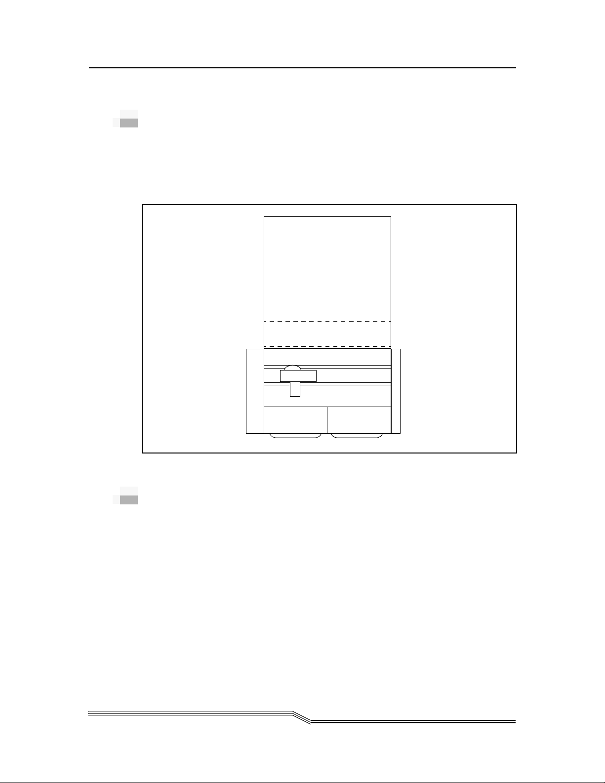
Handling Unit
The Handling Unit accomplishes the mechanical access to the
physical library storage and the drives via a robot. See Figure
2-2. The Handling Unit executes the PMAC commands and
returns status messages.
Figure 2-2 Handling Unit
2-6 System Description
600338-B
Page 21

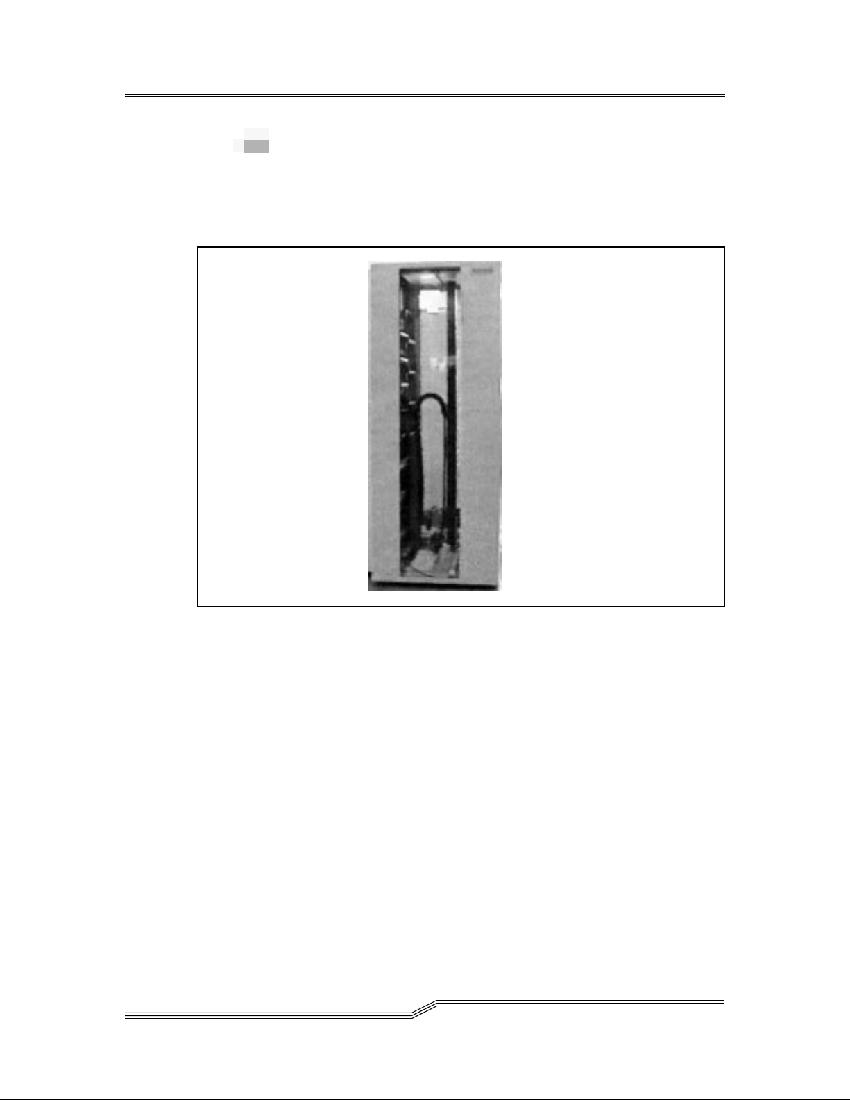
Robot
Media movements are performed by a robot. The robot is
equipped with a multimedia gripper and a laser barcode
scanner, see Figure 2-3. Typical movements include movin g
media into and out of the library, storing and retrieving media
within the library, mounting and di smounting media from
drive units, and scanning media barcode labels.
Components of the robot system include:
• Multimedia gripper.
• Laser barcode scanner
• Robot X Axis platform
• Robot Y Axis column
10 Oct 1996
Figure 2-3 Robot with Storage Bins
Hardware Components 2-7
Page 22
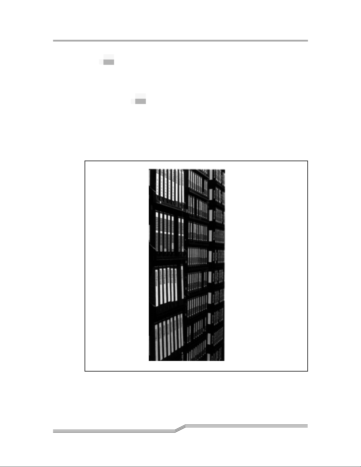
Storage Segment
The AML/J product line consists of a family of Linear Racks
for storage. Two Linear racks are maximum per base or
expansion unit.
Linear Racks
See Figure 2-4. Each Linear Rack contains two segments. The
segments consists of:
• rows which are media type dependent
• the number of positions per row (columns) also depends
on the media type
Figure 2-4 Linear racks
2-8 System Description
600338-B
Page 23
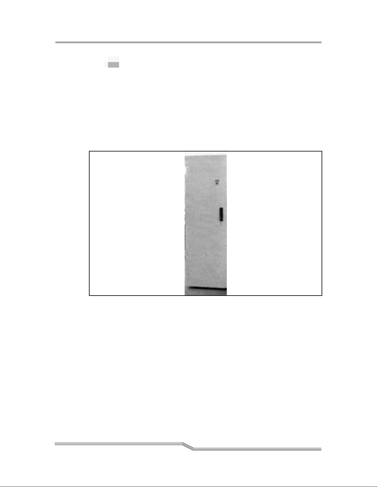
Drive/Control Cabinet
Movement control signals are provided by the PMAC which
resides in the Drive/Control Cabinet. See Figure 2-5. The
control cabinet contains:
•AMU
•PMAC
• Power supply
•Drives
• Drive Controller (optional for some drives)
10 Oct 1996
Figure 2-5 Drive/Control Cabinet
Hardware Components 2-9
Page 24
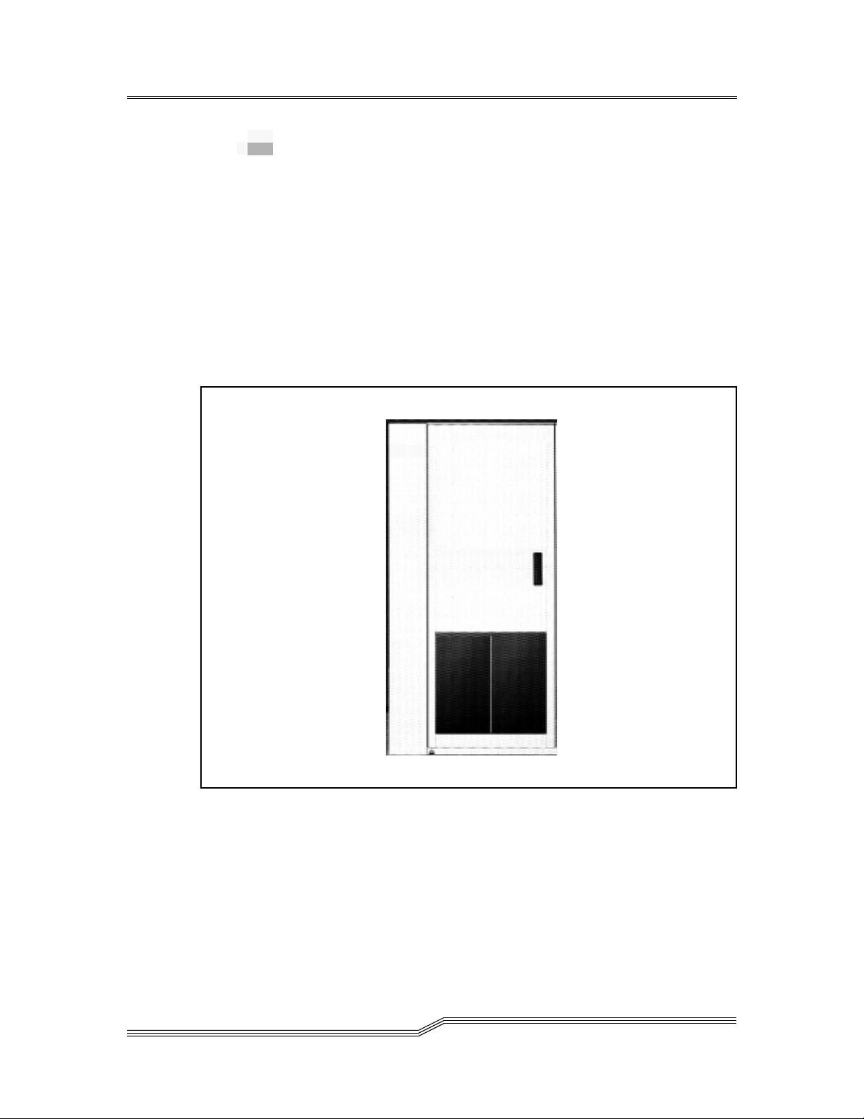
Insert/Eject Unit
Media are inserted into and ej ected from th e AML/ J through
the I/EF. The media are loaded by an operator into bins.
Two types of IE/F are offered. With the base AML/J
Insert/Eject Unit, the media is entered or retrieved through
the door. See Figure 2-6. With the IE/F-D, the door must be
opened to insert or retrieve media. Refer to Figure 2-7 on page
2-11. The capacity and number of bins are determined by the
type of IE/F and media.
The I/EF incorporates a media depository that stores
unidentified volumes, defective media, and used cleaning
devices.
Figure 2-6 Insert/Eject Unit
2-10 System Description
600338-B
Page 25
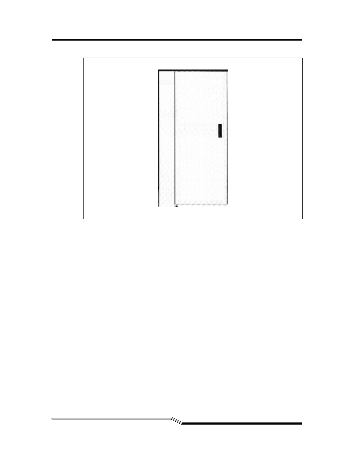
Figure 2-7 Insert/Eject Unit (IE/F-D)
10 Oct 1996
Hardware Components 2-11
Page 26

Expansion Unit
Note
The media
Expansion Unit
does not require a
corresponding
Drive Expansion
Unit.
The Expansion Unit was designed to increase the capacity of
the AML/J. Additional Insert/Eject units and additional
media are available through the Expansion Unit. See
Figure 2-8.
Figure 2-8 Expansion Unit
Note
For each
additional Drive
Expansion Unit, a
corresponding
media Expansion
Unit is required.
2-12 System Description
Drive Unit
The Drive Expansion Unit was designed to increase the
number of available tape drives in the AML/J.
600338-B
Page 27

Software Components
EMASS software organizes and manages the AML/J. This
software makes automated data manipulation possible
without interfering with the performance of host system.
EMASS software automatically receives messages,
coordinates tasks, manages and updates the library database,
and provides recovery from media errors.
EMASS software can be tailored for many different library
configurations. In addition, it can be reconfigured to
accommodate an expanding library.
MVS Support
Unlimited MVS system images support is provided by Host
Control Component (HCC-MVS) software. This software
integrates transparently with MVS S/370, S/390, and Sysplex
environments.
Host Control Component (HCC) software
Media functions are routed from the host computer to the
AMU AMS software. Media functions supported by HCC
software include the following:
• Mount/Keep oper ations
• Volume insertion/ejection
• Administration of media transport cleaning
• Media label initialization and verification
• Automatic reply to outstanding Write to Operator with
Reply (WTOR)
• Scratch media management
Communications functions between the host and AMU AMS
software are provided by the following means:
• Local or remote VTAM LU2 (standard 3270 support)
• EXCP standard console communication (local NON-SNA
3x74 control unit)
• LU6.2 (APPC via Token-Ring or Ethernet adapter)
10 Oct 1996
Software Components 2-13
Page 28

Minimum software requirements to support EMASS software
in the MVS environment include the following:
• MVS-SP1.3.6 for JES2
• MVS-SP2.2 for JES3
•SMP/E
• Assembler H
• Standard MVS utilities
UNIX Support
Software solutions to accessing a media libraries are
implemented through the UNIX virtual file system layer.
AMASS software
AMASS software presents the AML/J library as o n-line direct
access mass storage. The AMASS software provides the
following features:
• The AML/J library appears a single device
• The AML/J library utilizes a single mount point
• The data on the media appears as a standard UNIX
directory with files
• Write or read to media utilizes the same approach as
magnetic disk
• Raw cache partitioning provide high performance
2-14 System Description
Files are accessible across the network through standard
communication protocol. The protocols include:
•NFS
•TCP/IP
•RFS
•FTP
•Telnet
• HYPERchannel
Requirements to support AMASS software are platform
dependent. Additional detailed information is provided in
the part number
600307 AMASS Documentation Set
manuals.
DataMgr software
DataMgr is an integrated, layered, file migration application
that requires and operates with AMASS software. DataMgr
provides the following features:
600338-B
Page 29

• Fully distributed architecture
• File migration from expensive magnetic disk space to
inexpensive storage media
• Transparent access to the migrated files
• Convenient access to migrated data during reloads
• Flexible migration policies determine the criteria for file
relocation
• File replication across distributed servers
• Multi-tier migration
Additional detailed information is provided in the part
number
600336 DataMgr Documentation Set
manuals.
FileServ software
FileServ software balances on-line media with stored library
media fro quick access to data. The FileServ software provides
the following features:
• The data on the media is accessed via standard UNIX
operations using filesystem(s) as tracking points
• Tracks multiple users of the same file to prevent multiple
mount actions
• File migration from expensive magnetic disk space to
inexpensive storage media
• Transparent access to the migrated files
• Flexible migration policies determine the criteria for file
relocation
• Media error are retained as a means to identify suspect
defective media
Files are accessible across the centralized or distributed
environments through:
• Ethernet
•FDDI
• HYPERchannel
• UltraNet
®
Requirements to support FileServ software are platform
dependent. Additional detailed information is provided in the
part number
600309 FileServ Documentation Set (for SGI)
manuals and the part number
Documentation Set (for Convex)
600255-01 FileServ
manuals.
10 Oct 1996
Software Components 2-15
Page 30

VolServ software
VolServ software handles volume manipulation by class of
data and media migration. The Volserv software provid es the
following features:
• Provides a robotic independent interface to a variety of
robotic systems
• Determines on-line or stored media volume location
• Issues manual or robotic commands to retrieve and
mount media
• Allows multiple clients to sha r e a single media library
• User defined classes of media share a media library
• Supports multiple media types
• Pools drives to allow drives to be shared among clients
• User defined migration policy allows media to be
migrated between on-line and off-line storage
Once a media volume is mounted, the files are accessible
across the centralized or distributed environments through:
• Ethernet
•FDDI
• HYPERchannel
• UltraNet
®
Requirements to support VolServ software are platform
dependent. Additional detailed information is provided in
the part number
and the part number
manuals.
SUN)
600308-01 VolServ Documentation Set (for SGI)
600308-02 VolServ Documen tation Set (f or
DAS software
The distributed AML Server (DAS) is a software product with
both client and server components. The server software
modules support the OS/2 operating system platform and the
client software modules support UNIX/AIX operating
system platforms. They communicate from the UNIX/A IX
clients to the OS/2 DAS server (AMU controller PC) across a
TCP/IP connected network.
2-16 System Description
600338-B
Page 31

DAS allows client systems to request actions on selected
media within the AML system. DAS performs the following
requested actions:
• mounts media in a drive
• dismounts media from a drive
• inserts media into the library
• ejects media from the library
Requirements to support DAS software are platform
dependent.
Archive Management Software Support
Operating in the OS/2 environment, AMU software consists
of five proprietary operational processes and two proprietary
utility processes. The task of each of the seven processes are
listed below:
• Communication with host computer, robot control,
Quadro Tower control, and Hexa Tower control
• Management of the library catalog using Source Query
Language (SQL) database
• Kernel logic converts host commands into control
commands
• User interface for operator requests
• Log and trace connection
• Database backup facility
• Remote file transfer
10 Oct 1996
In normal (Automatic) operating mode, the host computer
directs the AML/J and the AMU software operates
transparently. Usually, commands are only input at the AMU
console through the Graphical User Interface (GUI) for direct
operator intervention.
Software Components 2-17
Page 32

2-18 System Description
600338-B
Page 33

3
System
Specification
Overview . . . . . . . . . . . . . . . . . . . . . . . . . . . . . . . . . . . . . . . . . . . . . . . . . . . . . . . . . . . . . . .3-3
Physical Specifications . . . . . . . . . . . . . . . . . . . . . . . . . . . . . . . . . . . . . . . . . . . . . . . . . . . .3-3
Electrical Specifications . . . . . . . . . . . . . . . . . . . . . . . . . . . . . . . . . . . . . . . . . . . . . . . . . . .3-4
Performance Specifications . . . . . . . . . . . . . . . . . . . . . . . . . . . . . . . . . . . . . . . . . . . . . . . .3-5
Environmental Specifications . . . . . . . . . . . . . . . . . . . . . . . . . . . . . . . . . . . . . . . . . . . . . .3-5
Regulatory Specifications . . . . . . . . . . . . . . . . . . . . . . . . . . . . . . . . . . . . . . . . . . . . . . . . . .3-5
Media Quantity Specification . . . . . . . . . . . . . . . . . . . . . . . . . . . . . . . . . . . . . . . . . . . . . .3-6
Flooring Requirements . . . . . . . . . . . . . . . . . . . . . . . . . . . . . . . . . . . . . . . . . . . . . . . . . . . .3-8
Barcode Requirements . . . . . . . . . . . . . . . . . . . . . . . . . . . . . . . . . . . . . . . . . . . . . . . . . . . .3-8
Page 34

3-2 System Specification
600338-B
Page 35

Overview
This section contains the following information for the
AML/J library:
• Physical Specification
• Electrical Specification
• Performance Specification
• Environmental Specification
• Regulatory Specifications
• Media Quantity Specification
• Flooring Requirement
• Barcode Requirement
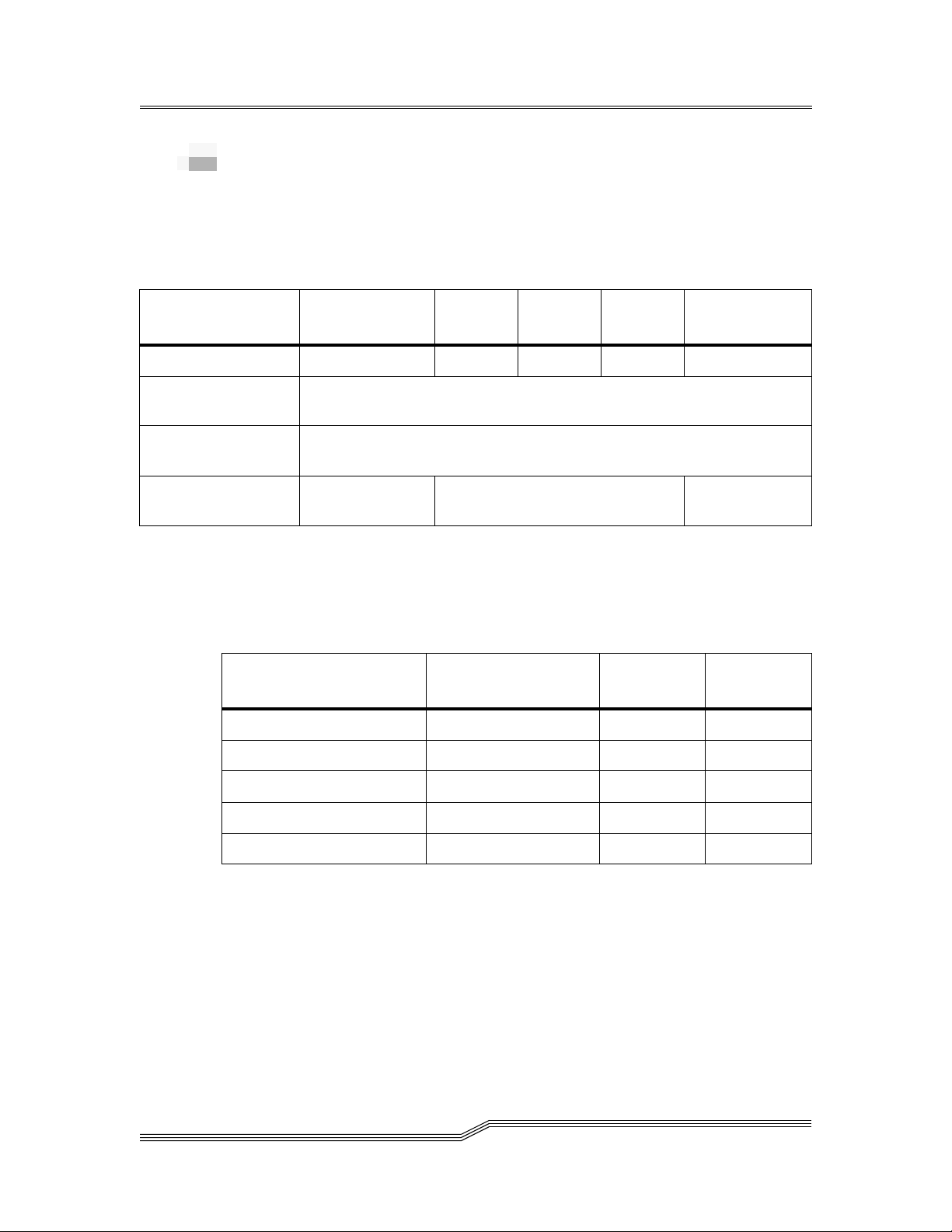
Physical Specifications
Table 3-1 lists the key physical information for the
components of the AML/J library.
3-
Table 3-1
AML/J Component Physical Dimensions
Device Height Width Depth
1
Control Cabinet 78 inches 29
Model J Base
Module
b
Model J Expansion
78 inches 42
78 inches 29
/8 inches 29 1/4 inches 524 lbs
3
/4 inches 32 1/2 inches 720 lbs 75 lbs/sq ft
1
/8 inches 31 1/4 inches 690 lbs 110 lbs/sq ft
Module
1
Drive Expansion
78 inches 29
/8 inches 29 1/4 inches 850
Cabinet
a. Includes the weight of the heaviest available drive.
b. Cabinet width includes 8 3/4 inch left side non-movable panel and
7
4
/8 inch right side movable panel as viewed from the front.
c. See Footnote a.
Maximum
Weight
a
c
Load
88 lbs/sq ft
144 lbs/sq ft
10 Oct 1996
Overview 3-3
Page 36
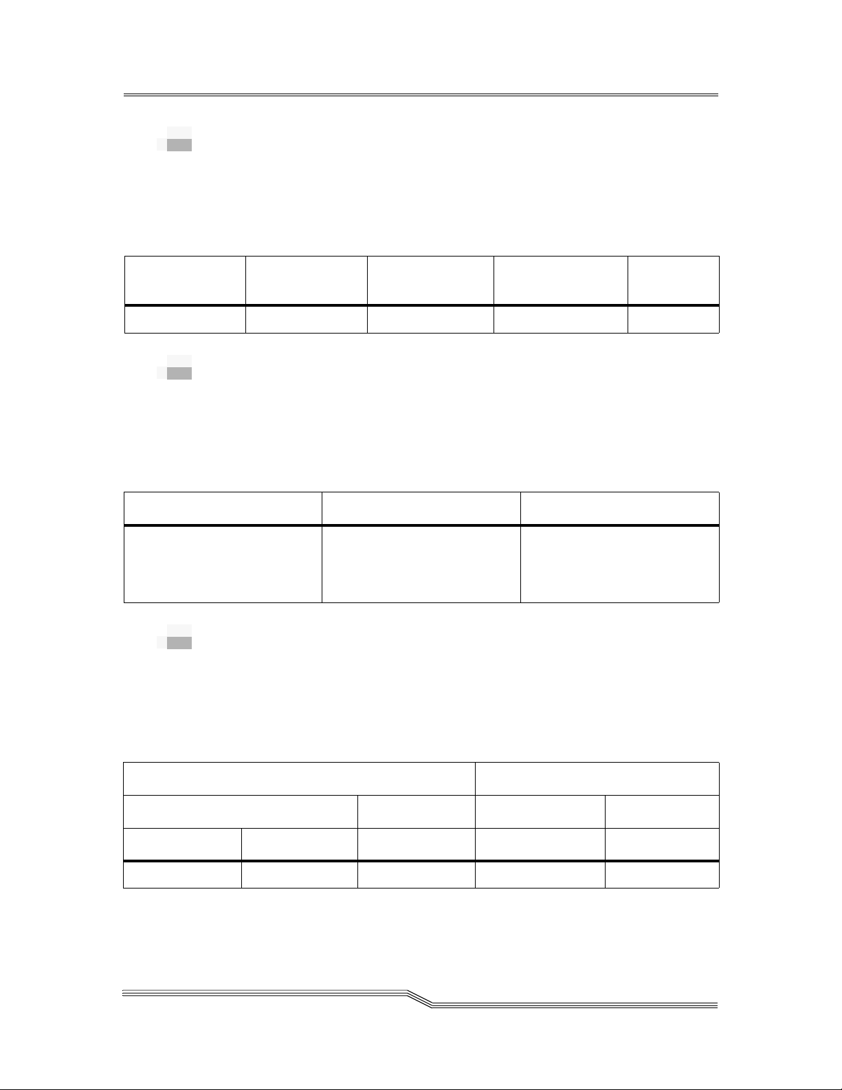
Electrical Specifications
Table 3-2 lists the key electrical information for the
components of the AML/J library.
Table 3-2
Device
Control Cabinet 120 VAC 0.7 6 2135 L5-15R
Model J Base
Module
Model J Expansion
Module
Drive Expansion
Cabinet
Table 3-3
AML/J Component Electrical Specifications
Voltage
(Single Phase)
120 VAC Tape Drive Dependent L5-15R
Table 3-3 lists the key electrical specifications of the EMASS
drive components for the AML/J.
AML/J Drive Component Electrical Specification
Device
kVA AMP BTU Receptacle
Not Applicable
Not Applicable
Voltage
(Single Phase)
AMP BTU
EMASS 8490 120 VAC 5 225
EMASS 8590 120 VAC 3 1024
EMASS DLT4002 120 VAC 2 340
EMASS DTF1242 120 VAC 3 598
EMASS ER90 120 VAC 2 1706
3-4 System Specification
600338-B
Page 37
Performance Specifications
Table 3-4 lists the key performance information for the
AML/J library.
Table 3-4
Avg Actions
per Hour
300 400 2.5 seconds 6 seconds 3 seconds
AML/J Performance Specifications
Peak Actions
per Hour
Avg Time to
Present Media
Max Time to
Present Media
Pick Time
Environmental Specifications
Table 3-5 lists the key environmental information for the
AML/J library.
Table 3-5
Temperature Humidity Altitude
Minimum to Maximum:
60° - 90° F (16° - 32° C)
Recommended:
70° - 75° F (21° - 24° C)
AML/J Environmental Specifications
Minimum to Maximum:
15 - 75 percent
Recommended:
45 - 65 percent
No limit
Regulatory Specifications
Table 3-6 lists the key safety and electromagnetic regulatory
information for the AML/J library.
Table 3-6
North America Europe North America Europe
UL CSA TUV Rhineland FCC, Part 15 CE Mark
UL1950 - ITE C22.2 #950 EN60950 Class A Class A
10 Oct 1996
AML/J Regulatory Specifications
Safety EMC - EMI
Performance Specifications 3-5
Page 38
3-6 System Specification
Media Quantity Specification
Table 3-7 lists the quantity of media contained in a single storage segment for the AML/J library.
Refer to the document number
configuration requirements.
Table 3-7 AML/J Media Segment Quantity
600300 AML Hardware Configuration Information
for capacity
Media J1
Half-Inch
a
110 90 60 40 20 100 70 40 130 30 90 30 260
J2
b
J3
c
J4
d
J5
e
J6fJ7
g
J8
h
J10
i
J11
j
J12
k
IE/F-ElIE/F-D
m
Cartridge
D-2 small
36 24 24 12 12 36 24 12 48 06 30 06 96
Cartridge
St-120 Cassette 48 40 32 16 08 40 32 08 56 08 40 08 112
DLT Cartridge 80 64 48 32 16 64 48 16 96 16 64 16 192
8-MM
99 81 63 36 18 81 63 18 117 27 81 27 224
Cartridge
4-MM
154 121 88 55 22 121 88 22 176 33 121 33 352
Cartridge
600338-B
Page 39

10 Oct 1996
Table 3-7 AML/J Media Segment Quantity (Continued)
Media J1
Optical Disk
a
88 66 55 33 11 66 55 11 99 22 66 22 189
J2
b
J3
c
J4
d
J5
e
J6fJ7
g
J8
h
J10
i
J11
j
J12
k
IE/F-ElIE/F-D
m
512
Optical Disk
96 72 60 36 12 72 60 12 108 24 72 24 216
Reflection
DTF small
56 48 32 24 8 48 32 8 72 16 48 16 144
Cartridge
a. Storage segment above 1 of 6 drive shelves
b. Storage segment above 2 of 6 drive shelves
c. Storage segment above 3 of 6 drive shelves
d. Storage segment above 4 of 6 drive shelves
e. Storage segment above 5 of 6 drive shelves
f. Storage segment above 1 of 4 drive shelves
g. Storage segment above 2 of 4 drive shelves
h. Storage segment above 3 of 4 drive shelves
i. Storage segment for a full height
Media Quantity Specification 3-7
j. Storage segment next to 1 IE/F-E
k. Storage segment ab ove IE/F - E
l. Storage segment IE/F-E
m. Storage segment IE/F -D
Page 40

Flooring Requirements
In addition to being dust-free, physically, chemically, and
acoustically appropriate, the flooring must meet the
insulation resistance specifications. The insulation resistance
between the floor surface and earth ground must be 1 x 10
8
1 x 10
ohms to prevent system failure or electrical shock.
Sufficient resistance is achieved by using antistatic,
nonconducting floor tile with a resistance of 1 x 10
ohms. Provide an appropriate connection to the m etal portion
of the ground plate as necessary to ensure the insulation
resistance.
Barcode Requirements
Barcode scanning of individual media labels is accurate if the
labels meets the ANSI MH10.8M-1983 standard and other
additional requirements. The requirements are:
• ANSI MH10.8M-1983 Standard
• Number of digits: 6
• Background reflection: at least 25 percent
• Print contrast: at least 75 percent
• Ratio: at least 2.2
• Module: 250 mm
• Print tolerance: ± 57 mm
5
6
to 1 x 10⁹
to
• Additional Requirements
• Length of the rest zones: 5.25 mm ± 0.25 mm
• No black marks can be present in the intermediate
spaces or rest zones
• No white areas may be present on the bars
• Bars should read in a uniform direction. Nonunifor m
reading directions are feasible in principle, but have a
detrimental effect on performance
• Each label should be applied in the upper right corner
of the tape cartridge recess (when oriented vertically)
• Quality Testing
Compliance with these specifications can be checked and
documented with the Ergilaser 3000 High Density bar code
measuring device that is manufactured by the Laetus
Company.
3-8 System Specification
600338-B
Page 41

4
System
Configuration
Overview . . . . . . . . . . . . . . . . . . . . . . . . . . . . . . . . . . . . . . . . . . . . . . . . . . . . . . . . . . . . . . .4-3
Base Level . . . . . . . . . . . . . . . . . . . . . . . . . . . . . . . . . . . . . . . . . . . . . . . . . . . . . . . . . . . . . . .4-3
Media Types . . . . . . . . . . . . . . . . . . . . . . . . . . . . . . . . . . . . . . . . . . . . . . . . . . . . . . . . . . . . .4-4
Drive Types . . . . . . . . . . . . . . . . . . . . . . . . . . . . . . . . . . . . . . . . . . . . . . . . . . . . . . . . . . . . .4-5
Insert/Eject Media Boxes . . . . . . . . . . . . . . . . . . . . . . . . . . . . . . . . . . . . . . . . . . . . . . . . . .4-6
Control Cabinet Drive Shelves . . . . . . . . . . . . . . . . . . . . . . . . . . . . . . . . . . . . . . . . . . . . .4-6
Drive Cabinet Drive Shelves . . . . . . . . . . . . . . . . . . . . . . . . . . . . . . . . . . . . . . . . . . . . . . .4-7
Base Unit Media Type Segments . . . . . . . . . . . . . . . . . . . . . . . . . . . . . . . . . . . . . . . . . . . .4-8
Expansion Unit Media Type Segments . . . . . . . . . . . . . . . . . . . . . . . . . . . . . . . . . . . . . .4-9
Modem . . . . . . . . . . . . . . . . . . . . . . . . . . . . . . . . . . . . . . . . . . . . . . . . . . . . . . . . . . . . . . . .4-10
Software Types . . . . . . . . . . . . . . . . . . . . . . . . . . . . . . . . . . . . . . . . . . . . . . . . . . . . . . . . .4-11
Host Connection . . . . . . . . . . . . . . . . . . . . . . . . . . . . . . . . . . . . . . . . . . . . . . . . . . . . . . . .4-11
Communication Software . . . . . . . . . . . . . . . . . . . . . . . . . . . . . . . . . . . . . . . . . . . . . . . .4-11
Special Engineering Request . . . . . . . . . . . . . . . . . . . . . . . . . . . . . . . . . . . . . . . . . . . . . .4-11
Customer System Layout . . . . . . . . . . . . . . . . . . . . . . . . . . . . . . . . . . . . . . . . . . . . . . . . .4-12
Page 42

4-2 System Configuration
600338-B
Page 43

Overview
Base Level
This section of the manual solicits the information necessary
to configure an AML/J library. Detailed information about
drive, media, and storage support for the AML/J is located in
the part number
Information
components is located in the path number
Order Information
Check (✔) the desired base level configuration.
Entry Level (2 drive shelves, 1 I/E unit)
Base Module
Base Model + 1 Expansion Unit
Base Model + 2 Expansion Units
600300 AML Hardware Configuration
manual. Order information for the AML/J
600302 Product
manual.
4-
Base Model + 3 Expansion Units
Base Model + 4 Expansion Units
Base Model + 5 Expansion Units
Base Model + 6 Expansion Units
Base Model + 7 Expansion Units
Base Model + 8 Expansion Units
Base Model + 9 Expansion Units
10 Oct 1996
Overview 4-3
Page 44

Media Types
Enter the quantity of the desired media type (maximum 4).
3480/3490E
EMASS 8490
EMASS 8590
OD512
OD-R
D2S
VHS
DLT
8mm
4mm
DTF small
DTF medium
other
4-4 System Configuration
600338-B
Page 45

Drive Types
Enter the quantity of the desired drive types (maximum 4) and
if the drive requires a rack mount.
Quantity Type Supported
(Yes or No)
Fujitsu 3490E Yes
EMASS 8490 Yes
IBM 3490 C1A Yes
IBM 3490 C2A Yes
EMASS 8590 Yes
MountainGate 2150 Yes
ER90 HiPPI Yes
ER90 IPI Yes
Exabyte 8mm Yes
Exabyte 4mm Yes
HP OD Yes
EMASS 4002 Yes
OTR Yes
DTF 1242 Yes
non-EMASS drive
Rack Mount
(Yes or No)
10 Oct 1996
Drive Types 4-5
Page 46

3480/3490E
EMASS 8490
EMASS 8590
OD512
OD-R
D2S
VHS
DLT
8mm
4mm
other
Insert/Eject Media Boxes
Enter the quantity of the requested media type handing
boxes.
I/E 1I/E 2I/E 3I/E 4I/E 5I/E 6
Drive
Shelves
Control
Cabinet
Control Cabinet Drive Shelves
Enter the quantity of the Control Cabinet Drive Shelves.
Check (✔) if any shelves are for EMASS 8490 (max 3),
EMASS 8590 (max 2), ER90 (max 2), DTF 1242 (max 2), or DLT
4002 (max 3).
Qty EMASS
8490
Yes No Yes No Yes No Yes No Yes No
EMASS
8590
ER90 DTF 1242 DLT 4002
4-6 System Configuration
600338-B
Page 47

Drive Cabinet Drive Shelves
Enter the quantity of Drive Shelves (maximum 6) for the desired
number of Drive Cabinet. Check (✔) if any shelves are for
EMASS 8490 (max 6), EMASS 8590(max 4), EMASS ER90 (max
4), DTF 1242 (max 4), or DLT 4002 (max 6) type drives.
Drive
Shelves
Drive
Cabinet 1
Drive
Cabinet 2
Drive
Cabinet 3
Drive
Cabinet 4
Drive
Cabinet 5
Drive
Cabinet 6
Qty EMASS
8490
Yes No Yes No Yes No Yes No Yes No
Yes No Yes No Yes No Yes No Yes No
Yes No Yes No Yes No Yes No Yes No
Yes No Yes No Yes No Yes No Yes No
Yes No Yes No Yes No Yes No Yes No
Yes No Yes No Yes No Yes No Yes No
EMASS
8590
ER90 DTF 1242 DLT 4002
10 Oct 1996
Drive Cabinet Drive Shelves 4-7
Page 48

Base Unit Media Type Segments
Note
There are two
segments in each
Insert/Eject
Facilities. A
Segment 5 is
available only if
one of two IE/F
segments is used
as a storage
segment.
Check (✔) the media type for each segment
Base Unit
Seg 1Seg 2Seg 3Seg 4
3480/3490E
EMASS 8490
EMASS 8590
OD512
OD-R
D2S
VHS
DLT
8mm
4mm
other
4-8 System Configuration
600338-B
Page 49
Expansion Unit Media Type Segments
Note
There are two
segments in each
Insert/Eject
Facilities. A
Segment 5 is
available only if
one of two IE/F
segments is used
as a storage
segment.
3480/3490E
EMASS 8490
EMASS 8590
OD512
OD-R
D2S
VHS
DLT
8mm
4mm
other
Check (✔) the media type for each segment
Expansion Unit 1 Expansion Unit 2
Seg 1 Seg 2 Seg 3 Seg 4 Seg 1 Seg 2 Seg 3 Seg 4
10 Oct 1996
Expansion Unit 3 Expansion Unit 4
Seg 1 Seg 2 Seg 3 Seg 4 Seg 1 Seg 2 Seg 3 Seg 4
3480/3490E
EMASS 8490
EMASS 8590
OD512
OD-R
D2S
VHS
DLT
8mm
4mm
other
Expansion Unit Media Type Segments 4-9
Page 50

3480/3490E
EMASS 8490
EMASS 8590
OD512
OD-R
D2S
VHS
DLT
8mm
4mm
other
3480/3490E
Expansion Unit 5 Expansion Unit 6
Seg 1 Seg 2 Seg 3 Seg 4 Seg 1 Seg 2 Seg 3 Seg 4
Expansion Unit 7 Expansion Unit 8
Seg 1 Seg 2 Seg 3 Seg 4 Seg 1 Seg 2 Seg 3 Seg 4
EMASS 8490
EMASS 8590
OD512
OD-R
D2S
VHS
DLT
8mm
4mm
other
Modem
Check (✔) if modem is desired.
Yes No
4-10 System Configuration
600338-B
Page 51
Software Types
Check (✔) the requested type of software.
HCC-MVS
AMASS
AMASS with DataMgr
FileServ
VolServ
DAS
Other
Host Connection
Check (✔) the requested type of connection.
Ethernet
Token Ring
Coax
Special
Communic ation Software
Check (✔) if Remote Access communication software is
desired (CM/2 and TCP/IP are included with the system).
Remote Access
Special Engineering Request
Check (✔) any desired special engineering requirements.
None
Hardware
Software
10 Oct 1996
Software Types 4-11
Page 52

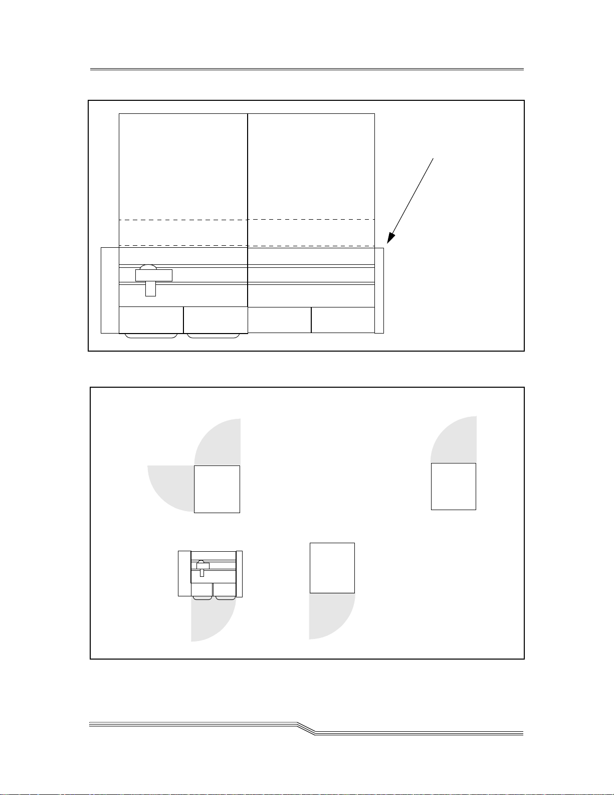
Customer System Layout
Sketch the customer’s system layout or cut and paste from the
examples in Figure 4-3 on page 4-13. Figure 4-2 on page 4-13
represents a configuration example.
Figure 4-1 Customer AML/J Configuration Layout
4-12 System Configuration
Scale: 1/4" = 1’
600338-B
Page 53
Drive/Control Cabinet
Media Shelves
This panel moves from the
end of the Base Cabinet
to the end of the last
Expansion Cabinet
Drive Expansion Cabinet
Robot
Insert/Eject
Facility
Insert/Eject
Facility
Expansion Cabine t
Media Shelves
Media Shelves
Figure 4-2 Example AML/J ConfigurationConfiguration
Drive/Control Cabinet
front
Base Expansion Cabinet
Base Cabinet
Drive Expansion Cabinet
front
10 Oct 1996
Figure 4-3 Cutout Examples
front
Service Area is gray
Scale: 1/4" = 1’
Customer System Layout 4-13
Page 54

4-14 System Configuration
600338-B
Page 55

5
Survey Data
Overview . . . . . . . . . . . . . . . . . . . . . . . . . . . . . . . . . . . . . . . . . . . . . . . . . . . . . . . . . . . . . . .5-3
General Information . . . . . . . . . . . . . . . . . . . . . . . . . . . . . . . . . . . . . . . . . . . . . . . . . . . . . .5-3
Physical Environment . . . . . . . . . . . . . . . . . . . . . . . . . . . . . . . . . . . . . . . . . . . . . . . . . . . . .5-4
Customer Room Layout . . . . . . . . . . . . . . . . . . . . . . . . . . . . . . . . . . . . . . . . . . . . . . . . . . .5-6
Site Preparation . . . . . . . . . . . . . . . . . . . . . . . . . . . . . . . . . . . . . . . . . . . . . . . . . . . . . . . . . .5-7
Power Circuits . . . . . . . . . . . . . . . . . . . . . . . . . . . . . . . . . . . . . . . . . . . . . . . . . . . . . . .5-7
Telephone Connection . . . . . . . . . . . . . . . . . . . . . . . . . . . . . . . . . . . . . . . . . . . . . . . . .5-7
Customer Building Layout . . . . . . . . . . . . . . . . . . . . . . . . . . . . . . . . . . . . . . . . .5-8
Access Conditions . . . . . . . . . . . . . . . . . . . . . . . . . . . . . . . . . . . . . . . . . . . . . . . . .5-9
Additional Comments . . . . . . . . . . . . . . . . . . . . . . . . . . . . . . . . . . . . . . . . . . . . . . . .5 -12
Page 56

5-2 Survey Data
600338-B
Page 57

Overview
This section solicits pertinent informa tion about the delivery
site. Record all requested general information.
General Information
5-
Place any additional info rmation in
page 5-12.
Customer Name:
Mailing Address:
Sales Contact:
Telephone:
Additional Comments
on
10 Oct 1996
EMASS Sales Rep:
EMASS Account Mgr:
Shipping Address:
Overview 5-3
Page 58

Installation Contact:
Telephone:
Target Installation Date:
Target Operational Date:
Physical Environment
Place any additional info rmation in
page 5-12.
Room Dimension:
Ceiling Height
Ceiling Projection
Additional Comments
on
5-4 Survey Data
Floor Type
600338-B
Page 59

Floor Load Capacity
Fire Protection
10 Oct 1996
Physical Environment 5- 5
Page 60

Customer Room Layout
Sketch the approximate measurements of the AML/J library
room and any obstructions.
Figure 5-1 Room Layout
5-6 Survey Data
Scale: 1/4" = 1’
600338-B
Page 61

Site Preparation
The following customer supplied circuits are necessary for the
proper installation and operation of the AML/J library.
Power Circuits
Note
This information
must be conveyed
to the customer to
enable site
preparation before
installation.
Note
This information
must be conveyed
to the customer to
enable site
preparation before
installation.
Refer to
Electrical Specifications
120 VAC, single phase, 15A, circuit terminated in a
NEMA L5-15R receptacle.
Telephone Connection
Refer to
Modem
Standard B1 analog telephone line terminating in an
RJ-11 connector. Each AMU requires a separate line for
the diagnostic modem.
on page 4-10.
on page 3-4
10 Oct 1996
Site Preparation 5-7
Page 62

Customer Building Layout
Sketch the building layout that indicates the route from the
loading dock to equipment final destination. Indicate
obstructions.
Figure 5-2 Building Scale
5-8 Survey Data
Grid = 1/4", No Scale
600338-B
Page 63

Access Conditions
Access to AML/J library room (elevator, stairs, door widths,
etc.):
Dimensions and Location of Smallest Door or Opening:
Loading Dock Specifications (dock height, type of ramps,
weather protection, etc.):
10 Oct 1996
Semitrailer Accessibility (Y or N): ________
Preferred/Required Local Carrier Company:
Site Preparation 5-9
Page 64

Where Can Trailer Be Left for Staging?
Availability of Material Ha ndling Equipment:
Location for Uncrating:
5-10 Survey Data
Preferred Time of Day for Unloading and Moving Materials:
Off Hours/Weekends Accessibilit y for Installation Team:
600338-B
Page 65

Procedure for Obtaining Building Passes:
Procedure for Scheduling the Elevator, Loading Dock, etc.:
Waste Disposal Considerations:
10 Oct 1996
Bargaining Unit Considerations:
Other Considerations:
Site Preparation 5-11
Page 66

Additional Comments
Record any additional information from other pages. For
reference purposes, note the page number with the
information. Add and number additional sheets as necessary.
5-12 Survey Data
600338-B
 Loading...