

Page 1

SOFTWARE BACKUP
AML/2
AUTOMATED
MIXED-MEDIA
LIBRARY
/JUNIOR
for Release 2.3.0
Order no. DOC E00 017-C
Page 2

Table of Contents
1 Description
2 KONFIG.DAT from version 2.3.0 (robot)
Robot 1 2 -1
Robot 2 2 -12
3 Parameter Files for Handling
PLW34907.DAT , PLW34909.DAT 3 -1
PLWDAT?.DAT 3 -2
4 Parameters of the Robot Amplifier
5 Machine Parameters RHO3 (robot)
6 Configuration File for Tower Control AML/2
7 Machine Parameter RHO3 (tower)
8 Parameters of the Tower Amplifier
599 DOC E00 017-C Software Backup AML/2 Page I
Page 3

Table of Contents
Page II Software Backup AML/2 599 DOC E00 017-C
Page 4

Description
1 Description
A software backup is necessary after each change on the AML system.
Change means also the reteaching of a drive or another unit.
After a small change or correction only the changed file must be saved.
The service technician is responsible for the actual backup.
The backup diskettes and the System Logbook are located under the keyboard of
the AMU PC.
Information
Please don’t change any values in the grey fields!
Backup diskettes
Diskette 1 - Robot & Tower software
In error situation, please check the files (size, creation date)
Directory Filename
ROBOT1\MOOG\
and
ROBOT2\MOOG\
140HLP.DEF
BA1G100.PRS
BA1G131.PRS
BA2G100.PRS
BA3G60.PRS
BA4G29.PRS
BA5G8.PRS
BA6G9.PRS
BOSCHTRM.CFG
BOSCHTRM.EXE
BIQ140-.001
599 DOC E00 017-C Software Backup AML/2 Seite 1 - 1
Page 5

Directory Filename
BIQ140E.002
BIQ140E.003
BIQ140E.004
A1G100.PRS
A1G131.PRS
A2G100.PRS
A3G60.PRS
A4G29.PRS
A5G8.PRS
A6G9.PRS
Description
ROBOT1\
and
ROBOT2\
MPRHO3.BIN
KONFIG.DAT
PLW3480.DAT
PLW34907.DAT
PLW34909.DAT
PLWDATx.DAT
VERSION.DAT
Seite 1 - 2 Software Backup AML/2 599 DOC E00 017-C
Page 6

Description
Directory Filename
ROBOT\ IQ_ROBO.P2X
AMULESES.IRD
AMUSCHRS.IRD
EXPROG.DAT
INIT.IRD
KOPPLUNG.DAT
PERMAN.IRD
SBARCODE.IRD
PLW3480.IRD
PLW3490.IRD
PL WMULTI.IRD
SNEWGRIP.IRD
SRACK.IRD
STEACH.IRD
STEST.DAT
STEST.IRD
TOWER\ AMULESE.IRD
AMUSCHR.IRD
EXPROG.DAT
INIT.IRD
KOPPLUNG.DAT
PERMAN.IRD
QTURM1.IRD
QTURM2.IRD
QTURM3.IRD
TEST.DAT
TEST.GER
TEST.IRD
IQ_TURM.P2X
599 DOC E00 017-C Software Backup AML/2 Seite 1 - 3
Page 7

Directory Filename
Description
TOWER1-3\
and
TOWER4-6\
TOWER1-3\MOOG\
and
TOWER4-6\MOOG\
MPRHO3.BIN
KONFIG.DAT
140HLP.DEF
BIQ140-.001
BIQ140E.002
BIQ140E.003
BIQ140E.004
BHTURM.PRS
BNTURM.PRS
BOSCHTRM.CFG
BOSCHTRM.EXE
HTURM.PRS
NTURM.PRS
Seite 1 - 4 Software Backup AML/2 599 DOC E00 017-C
Page 8

Description
Diskette 2 - AMU Installation Diskette
Diskette 3 - actual updates from AMU software
- AMU*.ZIP
-INSTALL.CMD
- PKUNZIP2.EXE
- Directory \SYSTEM\
- AMUCONF.INI
- AMUCONST.INI
- CONFIG.SYS
- (CONCONT.INI)
- KRNREFPT.R01
- (KRNREFPT.R02)
-STARTUP.CMD
- Directory \CM\
Directory Filename Communication Type
C:\CMLIB\ AMU3270.* EXCP
AMU62S.* LU 6.2 Single Session
AMU62SC.* LU 6.2 Single Session
with additional Coax
AMU62P.* LU 6.2 Parallel Session
AMU62PC.* LU 6.2 Parallel Session
with additional Coax
BOCA.* only DCAF connection
C:\IBMCOM PROTOCOL.INI LANAdapter and Protocol
Support
C:\TCPIP\BIN TCP-
TCP/IP
START.CMD
C:\MPTN\ETC SETUP.CMD
TCP/IP
HOSTS
Diskette 4 - Backup of the database
599 DOC E00 017-C Software Backup AML/2 Seite 1 - 5
Page 9

Description
Seite 1 - 6 Software Backup AML/2 599 DOC E00 017-C
Page 10

KONFIG.DAT from version 2.3.0 (robot)
2 KONFIG.DAT from version 2.3.0 (robot)
Customer:
Installed:
Changes:
actual Version:
2.1 Robot 1
Pos. Line Parameter Default Actual Information
Addresses
1 12 T_ADR_RHO O01 Logical address of the control unit
(samesyntaxas AMU configuration:
O01).
2 13 T_EA1_TYP E0 Type of the first I/O unit ( same syn-
tax as AMU: E0, E1, ...).
The I/O unit/B control runs on the
robot control.
3 14 T_EA2_TYP -- Type of the second I/O unit.
4 15 G_EA1_Nr 1 Logical number of the first
I/O unit.
E001... means value 1
5 16 G_EA2_Nr 0 Logical number of the second
I/O unit.
6 17 G_ROBOTNR 1 Logical number of the robot.
1 = robot 1
2 = robot 2
Configuration of cartridge types
C0 - 1/2″ cartridge 34x0 + 3590
C1 - cartridge DLT
C2 - reseved
O0 - optical disk Reflection
O1 - optical disk 512
V0 - VHS cartridges V5 - Travan
V1-cartridge8mm V6-DTFsmall
V2-cartridge4mm V7-DTFlarge
V3 - D2 small cartridges V8 - BetaCAM small
V4 - D2 medium cartridges V9 - BetaCAM large
Use for each mediatype always the affiliated values,
eg media type 1 -> Offset media type 1, barcoderecognition media type 1 etc.
7 21 Z_Cart_Type1 -- media type 1
8 22 Z_Cart_Type2 -- media type 2
9 23 Z_Cart_Type3 -- media type 3
10 24 Z_Cart_Type4 -- media type 4
599 DOC E00 017-C Software Backup AML/2 Seite 2 - 1
Page 11

Robot 1
Pos. Line Parameter Default Actual Information
11 25 Z_Cart_Type5 -- media type 5
Calibration point coordinates (right arm) of media type 1 (NewGrip)
The NewGrip position is located on the robot console.
The controller needs for the media handling the arm values:
Positions 12 - 14 -> coordinates for right arm (media type 1)
Positions27 - 29 -> coordinatesf or left arm (media type 1)
12 29 FP_NewGripR[1].X_K 386.0 scanner: x-coordinate (in mm)
vision systemdefault: 395.0
13 30 FP_NewGripR[1].Y_K -230.0 scanner: y-coordinate (in mm)
vision systemdefault: 0.0
14 31 FP_NewGripR[1].Z_K 90.0 scanner: z-coordinate (in mm)
vision systemdefault: 80.0
Calibration point coordinates of media type 2 (NewGrip)
15 35 FP_NewGripR[2].X_K 386.0 x-coordinate (in mm)
16 36 FP_NewGripR[2].Y_K -230.0 y-coordinate (in mm)
17 37 FP_NewGripR[2].Z_K 90.0 z-coordinate (in mm)
Calibration point coordinates of media type 3 (NewGrip)
18 41 FP_NewGripR[3].X_K 386.0 x-coordinate (in mm)
19 42 FP_NewGripR[3].Y_K -230.0 y-coordinate (in mm)
20 43 FP_NewGripR[3].Z_K 90.0 z-coordinate (in mm)
Calibration point coordinates of media type 4 (NewGrip)
21 47 FP_NewGripR[4].X_K 386.0 x-coordinate (in mm)
22 48 FP_NewGripR[4].Y_K -230.0 y-coordinate (in mm)
23 49 FP_NewGripR[4].Z_K 90.0 z-coordinate (in mm)
Calibration point coordinates of media type 5 (NewGrip)
24 53 FP_NewGripR[5].X_K 386.0 x-coordinate (in mm)
25 54 FP_NewGripR[5].Y_K -230.0 y-coordinate (in mm)
26 55 FP_NewGripR[5].Z_K 90.0 z-coordinate (in mm)
Calibration point coordinates (left arm) of media type 1
The calibration point coordinates (left arm) of the other media types resultfrom
the following parameters.
27 59 FP_NewGripL[1].X_K 375.0 x-coordinate (in mm)
28 60 FP_NewGripL[1].Y_K 224.0 y-coordinate (in mm)
29 61 FP_NewGripL[1].Z_K 90.0 z-coordinate (in mm)
Seite 2 - 2 Software Backup AML/2 599 DOC E00 017-C
Page 12

Robot 1
Pos. Line Parameter Default Actual Information
Offset barcode recognition for rack (tower or linear shelf) media type 1 [1/100 mm]
30 65 FG_X_BC_Rack[1] 0 positivex-val.= gripper forward
31 66 FG_Y_BC_Rack[1] 0 positivey-value= gripper left
32 67 FG_Z_BC_Rack[1] 0 positive z-value = gripper up
Offset barcode recognition for rack (tower or linear shelf) media type 2 [1/100 mm]
33 71 FG_Y_BC_Rack[2] 0 positivey-value= gripper left
34 72 FG_Z_BC_Rack[2] 0 positive z-value = gripper up
Offset barcode recognition for rack (tower or linear shelf) media type 3 [1/100 mm]
35 76 FG_Y_BC_Rack[3] 0 positivey-value= gripper left
36 77 FG_Z_BC_Rack[3] 0 positive z-value = gripper up
Offset barcode recognition for rack (tower or linear shelf) media type 4 [1/100 mm]
37 81 FG_Y_BC_Rack[4] 0 positivey-value= gripper left
38 82 FG_Z_BC_Rack[4] 0 positive z-value = gripper up
Offset barcode recognition for rack (tower or linear shelf) media type 5 [1/100 mm]
39 86 FG_Y_BC_Rack[5] 0 positivey-value= gripper left
40 87 FG_Z_BC_Rack[5] 0 positive z-value = gripper up
Offset barcode recognition for I/O unit media type 1 [1/100 mm]
41 91 FG_X_BC_EA[1] 0 positive x-val. = gripper forward
42 92 FG_Y_BC_EA[1] 0 positive y-value = gripper left
43 93 FG_Z_BC_EA[1] 0 positive z-value = gripper up
Offset barcode recognition for I/O unit media type 2 [1/100 mm]
44 97 FG_Y_BC_EA[2] 0 positive y-value = gripper left
45 98 FG_Z_BC_EA[2] 0 positive z-value = gripper up
Offset barcode recognition for I/O unit media type 3 [1/100 mm]
46 102 FG_Y_BC_EA[3] 0 positive y-value = gripper left
47 103 FG_Z_BC_EA[3] 0 positive z-value = gripper up
Offset barcode recognition for I/O unit media type 4 [1/100 mm]
48 107 FG_Y_BC_EA[4] 0 positive y-value = gripper left
49 108 FG_Z_BC_EA[4] 0 positive z-value = gripper up
Offset barcode recognition for I/O unit media type 5 [1/100 mm]
50 112 FG_Y_BC_EA[5] 0 positive y-value = gripper left
51 113 FG_Z_BC_EA[5] 0 positive z-value = gripper up
599 DOC E00 017-C Software Backup AML/2 Seite 2 - 3
Page 13

Robot 1
Pos. Line Parameter Default Actual Information
Offset gripper handling for rack (tower or linear shelf) media type 1 [1/100 mm]
52 117 FG_X_DelRack[1] 0 positive x-val. = gripper forward
53 118 FG_Y_DelRack[1] 0 positive y-value = gripper left
54 119 FG_Z_DelRack[1] 0 positive z-value = gripper up
Offset gripper handling for rack (tower or linear shelf) media type 2 [1/100 mm]
55 123 FG_X_DelRack[2] 0 positive x-val. = gripper forward
56 124 FG_Y_DelRack[2] 0 positive y-value = gripper left
57 125 FG_Z_DelRack[2] 0 positive z-value = gripper up
Offset gripper handling for rack (tower or linear shelf) media type 3 [1/100 mm]
58 129 FG_X_DelRack[3] 0 positive x-val. = gripper forward
59 130 FG_Y_DelRack[3] 0 positive y-value = gripper left
60 131 FG_Z_DelRack[3] 0 positive z-value = gripper up
Offset gripper handling for rack (tower or linear shelf) media type 4 [1/100 mm]
61 135 FG_X_DelRack[4] 0 positive x-val. = gripper forward
62 136 FG_Y_DelRack[4] 0 positive y-value = gripper left
63 137 FG_Z_DelRack[4] 0 positive z-value = gripper up
Offset gripper handling for rack (tower or linear shelf) media type 5 [1/100 mm]
64 141 FG_X_DelRack[5] 0 positive x-val. = gripper forward
65 142 FG_Y_DelRack[5] 0 positive y-value = gripper left
66 143 FG_Z_DelRack[5] 0 positive z-value = gripper up
Offset gripper handling for I/O unit media type 1 [1/100 mm]
67 147 FG_X_DelEA[1] 0 positive x-val. = gripper forward
68 148 FG_Y_DelEA[1] 0 positive y-value = gripper left
69 149 FG_Z_DelEA[1] 0 positive z-value = gripper up
Offset gripper handling for I/O unit media type 2 [1/100 mm]
70 153 FG_X_DelEA[2] 0 positive x-val. = gripper forward
71 154 FG_Y_DelEA[2] 0 positive y-value = gripper left
72 155 FG_Z_DelEA[2] 0 Positive z-value = gripper up
Offset gripper handling for I/O unit media type 3 [1/100 mm]
73 159 FG_X_DelEA[3] 0 positive x-val. = gripper forward
74 160 FG_Y_DelEA[3] 0 positive y-value = gripper left
75 161 FG_Z_DelEA[3] 0 positive z-value = gripper up
Offset gripper handling for I/O unit media type 4 [1/100 mm]
76 165 FG_X_DelEA[4] 0 positive x-val. = gripper forward
Seite 2 - 4 Software Backup AML/2 599 DOC E00 017-C
Page 14
Robot 1
Pos. Line Parameter Default Actual Information
77 166 FG_Y_DelEA[4] 0 positive y-value = gripper left
78 167 FG_Z_DelEA[4] 0 Positive z-value = gripper up
Offset gripper handling for I/O unit media type 5 [1/100 mm]
79 171 FG_X_DelEA[5] 0 positive x-val. = gripper forward
80 172 FG_Y_DelEA[5] 0 positive y-value = gripper left
81 173 FG_Z_DelEA[5] 0 Positive z-value = gripper up
Assignment of the drive types
Same syntax as AMU configuration: eg D3, D8, D9, DO...
Use for each drive type always the affiliated offsets.
Not used drive types you have to fill up with „-“.
82 177 LW1 -- drive type 1
83 178 LW2 -- drive type 2
84 179 LW3 -- drive type 3
85 180 LW4 -- drive type 4
86 181 LW5 -- drive type 5
87 182 LW6 -- drive type 6
88 183 LW7 -- drive type 7
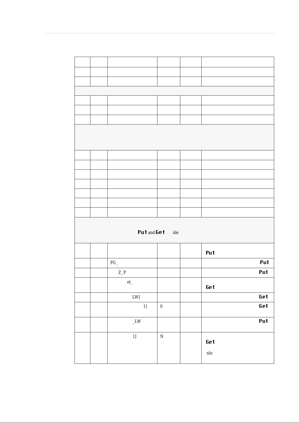
Parameters 63 - 98:
All parametersFG_Z_O... are only for OD drives.
They specify the offset for
Offset gripper handling and barcode recognition for drive type 1 [1/100 mm]
89 187 FG_X_Put_LW[1] 0 positive x-val. = gripperforward
90 188 FG_Y_Put_LW[1] 0 positive y-value= gripper left (
91 189 FG_Z_Put_LW[1] 0 positive z-value = gripper up (
92 190 FG_X_Get_LW[1] 0 positive x-val. = gripper forward
93 191 FG_Z_Get_LW[1] 0 positive z-value = gripperup (
94 192 FG_Z_ODB_LW[1] 0 positive z-value = gripper up (
95 193 FG_Z_ODP_LW[1] 0 positive z-value = gripper up (
Put
and
Get
of side B.
(
Put
)
(
Get
)
OD side B)
OD B-side)
Put
Get
Get
Put
Put
)
)
)
96 194 FZ_Unload[1] N Y = gripperpresses unload button
(
Get
),
N = gripperdoes not press the
unload button
599 DOC E00 017-C Software Backup AML/2 Seite 2 - 5
Page 15
Robot 1
Pos. Line Parameter Default Actual Information
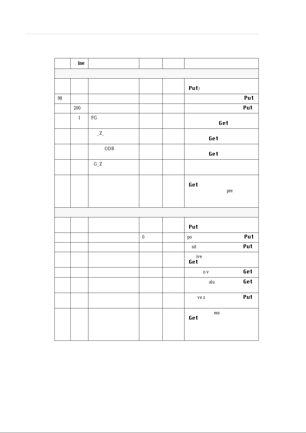
Offset gripper handling and barcode recognition for drive type 2 [1/100 mm]
97 198 FG_X_Put_LW[2] 0 positive x-val. = gripper forward
(
Put
)
98 199 FG_Y_Put_LW[2] 0 positive y-value= gripperleft (
99 200 FG_Z_Put_LW [2] 0 positive z-value = gripper up (
100 201 FG_X_Get_LW[2] 0 positive x-value (in 1/100 mm) =
gripperf orward (
101 202 FG_Z_Get_LW[2] 0 positive z-value (in 1/100 mm) =
gripperup (
102 203 FG_Z_ODB_LW[2] 0 positivez-value (in 1/100 mm) =
gripperup (
103 204 FG_Z_ODP_LW[2] 0 positive z-value (in 1/100 mm) =
gripperup (put OD side B)
104 205 FZ_Unload[2] N Y = gripperpresses unload button
(
Get
),
N = gripper does not press the
unloadbutton
Offset gripper handling and barcode recognition for drive unit type 3 [1/100 mm]
105 209 FG_X_Put_LW[3] 0 positive x-val. = gripper forward
(
Put
)
106 210 FG_Y_Put_LW[3] 0 positive y-value= gripperleft (
107 211 FG_Z_Put_LW[3] 0 positive z-value = gripper up (
Get
Get
Get
)
)
OD side B)
Put
Put
Put
Put
)
)
)
)
108 212 FG_X_Get_LW[3] 0 positive x-val. = gripper forward
(
Get
)
109 213 FG_Z_Get_LW[3] 0 positive z-value = gripper up (
110 214 FG_Z_ODB_LW[3] 0 positive z-value= gripper up (
OD B-side)
111 215 FG_Z_ODP_LW[3] 0 positive z-value = gripper up (
OD B-side)
112 216 FZ_Unload[3] N Y = gripperpresses unload button
Get
)
(
N = gripper does not press the
unloadbutton
Get
Get
Put
)
Seite 2 - 6 Software Backup AML/2 599 DOC E00 017-C
Page 16
Robot 1
Pos. Line Parameter Default Actual Information
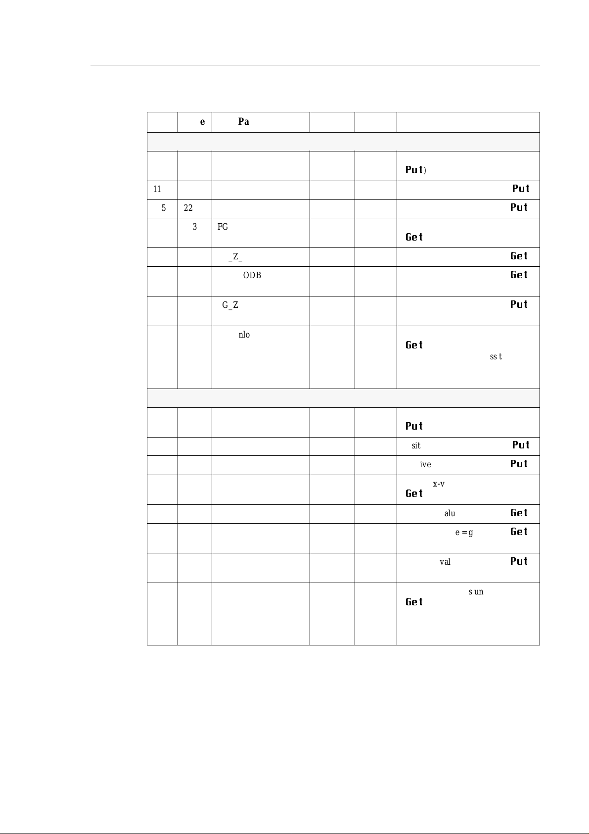
Offset gripper handling and barcode recognition for drive type 4 [1/100 mm]
113 220 FG_X_Put_LW[4] 0 positive x-val. = gripperforward
(
Put
)
114 221 FG_Y_Put_LW[4] 0 positive y-value= gripperleft (
115 222 FG_Z_Put_LW[4] 0 positive z-value = gripper up (
116 223 FG_X_Get_LW[4] 0 positive x-val. = gripper forward
(
Get
)
117 224 FG_Z_Get_LW[4] 0 positive z-value = gripper up (
118 225 FG_Z_ODB_LW[4] 0 positive z-value = gripper up (
OD side B)
119 226 FG_Z_ODP_LW[4] 0 positive z-value = gripper up (
OD side B)
120 227 FZ_Unload[4] N Y = gripper pressesunloadbutton
(
Get
),
N = gripperdoes not press the
unload button
Offset gripper handling and barcode recognition for drive type 5 [1/100 mm]
121 231 FG_X_Put_LW[5] 0 positive x-val. = gripper forward
(
Put
)
122 232 FG_Y_Put_LW[5] 0 positive y-value= gripperleft (
123 233 FG_Z_Put_LW[5] 0 positive z-value = gripper up (
Put
Put
Get
Get
Put
Put
Put
)
)
)
)
)
124 234 FG_X_Get_LW[5] 0 positive x-val. = gripper forward
Get
)
(
125 235 FG_Z_Get_LW[5] 0 positive z-value = gripper up (
126 236 FG_Z_ODB_LW[5] 0 positive z-value = gripper up (
OD side B)
127 237 FG_Z_ODP_LW[5] 0 positive z-value = gripper up (
OD side B)
128 238 FZ_Unload[5] N Y = gripper pressesunloadbutton
(
Get
),
N = gripperdoes not press the
unload button
Get
Get
Put
)
599 DOC E00 017-C Software Backup AML/2 Seite 2 - 7
Page 17
Robot 1
Pos. Line Parameter Default Actual Information
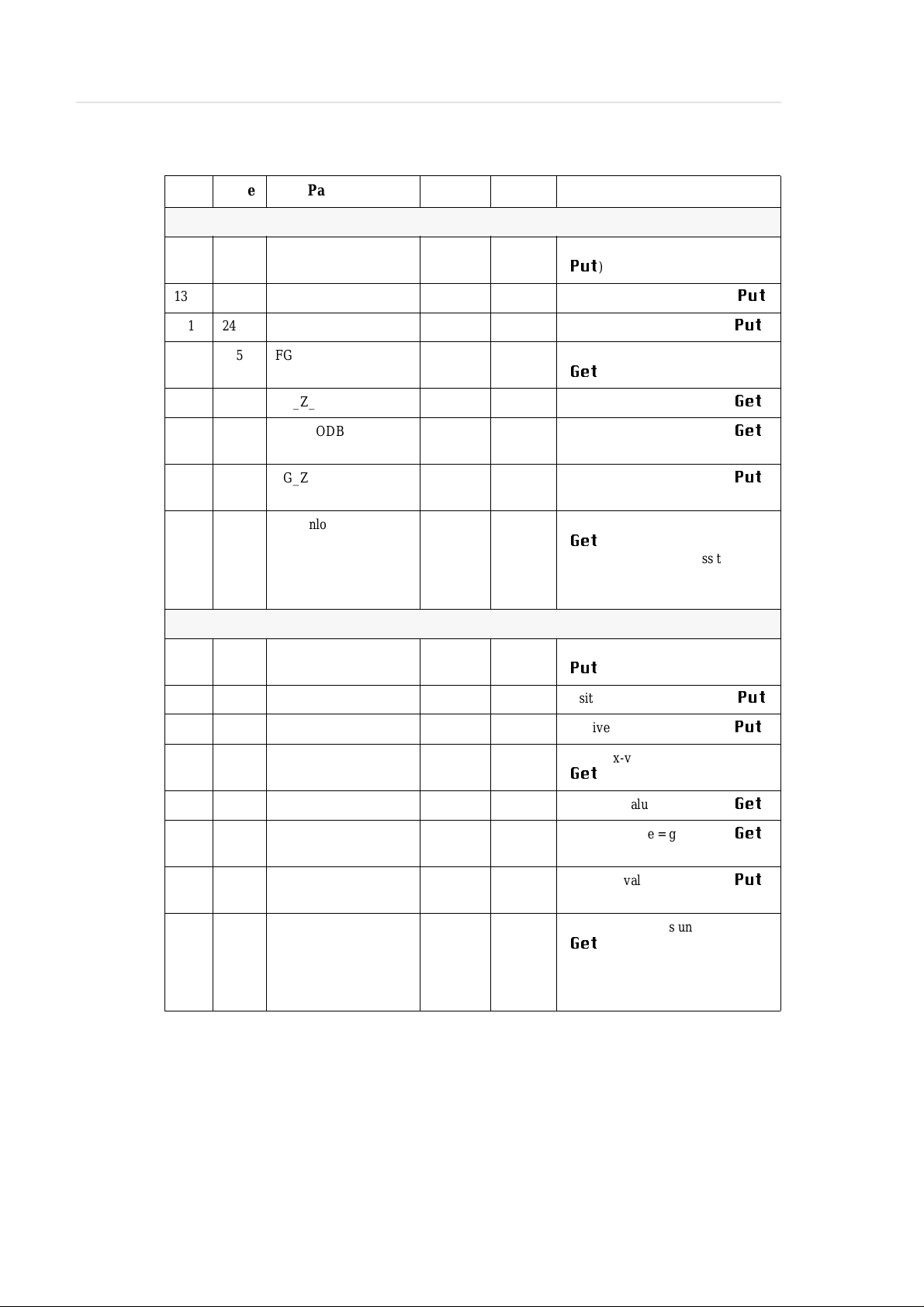
Offset gripper handling and barcode recognition for drive type 6 [1/100 mm]
129 242 FG_X_Put_LW[6] 0 positive x-val. = gripper forward
(
Put
)
130 243 FG_Y_Put_LW[6] 0 positive y-value= gripperleft (
131 244 FG_Z_Put_LW[6] 0 positive z-value = gripper up (
132 245 FG_X_Get_LW[6] 0 positive x-val. = gripper forward
(
Get
)
133 246 FG_Z_Get_LW[6] 0 positive z-value = gripper up (
134 247 FG_Z_ODB_LW[6] 0 positive z-value = gripper up (
OD side B)
135 248 FG_Z_ODP_LW[6] 0 positivez-value = gripper up (
OD side B)
136 249 FZ_Unload[6] N Y = gripperpresses unload button
(
Get
),
N = gripper does not press the
unloadbutton
Offset gripper handling and barcode recognition for drive type 7 [1/100 mm]
137 253 FG_X_Put_LW[7] 0 positive x-val. = gripper forward
(
Put
)
138 254 FG_Y_Put_LW[7] 0 positive y-value= gripperleft (
139 255 FG_Z_Put_LW[7] 0 positive z-value = gripper up (
Put
Put
Get
Get
Put
Put
Put
)
)
)
)
)
140 256 FG_X_Get_LW[7] 0 positive x-val. = gripper forward
Get
)
(
141 257 FG_Z_Get_LW[7] 0 positive z-value = gripper up (
142 258 FG_Z_ODB_LW[7] 0 positive z-value = gripper up (
OD side B)
143 259 FG_Z_ODP_LW[7] 0 positivez-value = gripper up (
OD side B)
144 260 FZ_Unload[7] N Y = gripperpresses unload button
(
Get
),
N = gripper does not press the
unloadbutton
Get
Get
Put
)
Seite 2 - 8 Software Backup AML/2 599 DOC E00 017-C
Page 18

Robot 1
Pos. Line Parameter Default Actual Information
Software limits (depending on your system)
145 264 G_X_MAXLIMIT 290000 Dependson the length ofthesystem.
Handlingat the end of the system (I/
O unit) must be possible. You get
this value with the test program on
the PHG. value = x-axis + h-axis
146 265 G_X_MINLIMIT 25000 minimal x-coordinateof AMU
147 266 G_Z_MAXLIMIT 142000 maximal z-coordinate of AMU
G_Z_MAXLIMIT = V_max + Z _max
„MPRHO3.BIN“ P204
3. axis (v), 6. axis (z)
148 267 G_Z_MINLIMIT -4500 -4500 minimal z-coordinate of AMU
149 268 G_H_SAVEELBO 100 Maximal h-coordinatefor a secure
arm change. You get this value with
the test program on the PHG: media
in gripper, arm in straight position,
drive to the first obstacle (eg the I/O
unit).
Speed and Acceleration
150 272 D_V_HANDL 250.0 Slow speed for linear interpolation
(during handling):
min. 10 / max. 250
Diagnosis
151 276 G_PHGECHO 1 0 = PHG not connected,
normal working conditions,
1 = PHG necessary,
tests possible,
2 = PHG connected,
only test mode,
stand-alone
3 = PHG connected,
only test mode,
stand-alone without gripper
Gripper offset (☞ gripper data sheet)
152 280 G_Y_BC 0 y-offset Scanner
153 282 G_X_TEACH 0 x-offset
154 283 G_Y_TEACH 0 y-offset
155 284 G_Z_TEACH 0 z-offset
Teach
Teach
Teach
156 286 G_X_OFFSET 0 gripper offset x-coordinate
(in 1/100 mm)
157 287 G_Y_OFFSET 0 gripper offset y-coordinate
(in 1/100 mm)
158 288 G_Z_OFFSET 0 gripper offset z-coordinate
(in 1/100 mm)
599 DOC E00 017-C Software Backup AML/2 Seite 2 - 9
Page 19

Robot 1
Pos. Line Parameter Default Actual Information
159 292 G_PARALLEL 1 Grippertype:
0=forsmallmedias
(401 004 930)
1 = for large medias
(401 004 920)
2 = Universal Gripper
(401 002 235)
160 293 G_BCErrIgn 1 Reaction on barcode-reading error.
0 = cancelon error
1 = ignore error and continue
161 295 G_Z_BCOff_V 0 Vertical offset (difference between
label for side A and side B) for the
barcodelabel on optical disks
162 296 G_WarnAus 0 Messages from type „Warning“will
not displayed in AMU-log when
G_WarnAus = 1
Timeout
163 300 D_TIME1 140 140 time-out Quadro tower(in sec)
164 301 D_TIME2 140 time-out I/O unit (in sec)
10 = I/O unit/B
165 302 D_WARTE_KEEP 60 time-out
166 306 D_Z_TO_V 0.27164 Relation between z- and v-axis.
Enter all values in mm and with 5
digits aftert he point.
Formulas:
max. z-axis = Z_max
(„MPRH3.BIN“P204,3. axis)
max. v-axis = V_max
(„MPRHO3.BIN“ P204, 6. axis)
D_Z_TO_V =
for D2 medium handling:
D_Z_TO_V =
167 307 D_Y_Elb 0 only for scanner gripper:
positive y-coordinate(in mm) in
world coordinates
for drive gripper with medium
use for touchless movement on track
(eg tower covering)
0 = normal processing
Keep
from drive
Z_max - 12
(Z_max - 12) + V_max
Z_max - 30
(Z_max - 30) + V_max
Coordinates (in mm) for special handling of drives on the start of track (only scanner gripper)
168 308 D_X_Col 0 x-coordinatefor begin handling area
(only for special handling in the
back area)
169 309 D_Y_Col 0 y-coordinate handling area (onlyfor
special handling in the back area)
Seite 2 - 10 Software Backup AML/2 599 DOC E00 017-C
Page 20

Robot 1
Pos. Line Parameter Default Actual Information
170 311 G_UMSCHLAG 1 Definition of the robotarm for front
handling:
0 = arm not defined
1=leftarm
2=rightarm
171 312 G_FIRSTOWER 1 Numberof first connected Quadro
tower
Additional offset value for
172 316 FG_Y_PRaOff[1] 0 media 1 on rack
173 317 FG_Y_PIEOff[1] 0 media 1 on I/O unit
174 318 FG_Y_PRaOff[2] 0 media 2 on rack
175 319 FG_Y_PIEOff[2] 0 media 2 on I/O unit
176 320 FG_Y_PRaOff[3] 0 media 3 on rack
177 321 FG_Y_PIEOff[3] 0 media 3 on I/O unit
178 322 FG_Y_PRaOff[4] 0 media 4 on rack
179 323 FG_Y_PIEOff[4] 0 media 4 on I/O unit
180 324 FG_Y_PRaOff[5] 0 media 5 on rack
181 325 FG_Y_PIEOff[5] 0 media 5 on I/O unit
182 329 0 0 reserve
183 330 0 0 reserve
184 331 0 0 reserve
185 332 0 0 reserve
186 333 0 0 reserve
PUT
(positive y-value (1/100mm) = gripper left)
Check sum
187 337 G_SUMME 187 187 number of positions in this file
599 DOC E00 017-C Software Backup AML/2 Seite 2 - 11
Page 21

2.2 Robot 2
Pos. Line Parameter Default Actual Information
Addresses
1 12 T_ADR_RHO O01 Logical address of the controlunit
2 13 T_EA1_TYP E0 Type of the first I/O unit (same syn-
3 14 T_EA2_TYP -- Type of the second I/O unit.
4 15 G_EA1_Nr 1 Logical number of the first
Robot 2
(samesyntaxasAMU configuration:
O01).
tax as AMU: E0, E1, ...).
The I/O unit/B control runs on the
robot control.
I/O unit.
E001... means value 1
5 16 G_EA2_Nr 0 Logical number of the second
I/O unit.
6 17 G_ROBOTNR 1 Logical number of the robot.
1=robot1
2=robot2
Configuration of cartridgetypes
C0 - 1/2″ cartridge 34x0 + 3590
C1 - cartridge DLT
C2 - reseved
O0 - optical disk Reflection
O1 - optical disk 512
Use for each media type alwaysthe affiliated values,
eg media type 1 -> Offset media type 1, barcoderecognition media type 1 etc.
7 21 Z_Cart_Type1 -- media type 1
8 22 Z_Cart_Type2 -- media type 2
9 23 Z_Cart_Type3 -- media type 3
10 24 Z_Cart_Type4 -- media type 4
11 25 Z_Cart_Type5 -- media type 5
V0 - VHS cartridges V5 - Travan
V1 - cartridge 8 mm V6 - DTF small
V2 - cartridge 4 mm V7 - DTF large
V3 - D2 small cartridges V8 - BetaCAM small
V4 - D2 medium cartridges V9 - BetaCAM large
Seite 2 - 12 Software Backup AML/2 599 DOC E00 017-C
Page 22

Robot 2
Pos. Line Parameter Default Actual Information
Calibration point coordinates(right arm) of media type 1 (NewGrip)
The NewGrip position is located on the robot console.
The controller needs for the media handling the arm values:
Positions 11 - 13 -> coordinates for right arm (media type 1)
Positions27 - 29 -> coordinates for left arm (media type 1)
12 29 FP_NewGripR[1].X_K 386.0 scanner: x-coordinate (in mm)
vision systemdefault: 395.0
13 30 FP_NewGripR[1].Y_K -230.0 scanner: y-coordinate (in mm)
vision systemdefault: 0.0
14 31 FP_NewGripR[1].Z_K 90.0 scanner: z-coordinate (in mm)
vision systemdefault: 80.0
Calibration point coordinates of media type 2 (NewGrip)
15 35 FP_NewGripR[2].X_K 386.0 x-coordinate (in mm)
16 36 FP_NewGripR[2].Y_K -230.0 y-coordinate (in mm)
17 37 FP_NewGripR[2].Z_K 90.0 z-coordinate(in mm)
Calibration point coordinates of media type 3 (NewGrip)
18 41 FP_NewGripR[3].X_K 386.0 x-coordinate (in mm)
19 42 FP_NewGripR[3].Y_K -230.0 y-coordinate (in mm)
20 43 FP_NewGripR[3].Z_K 90.0 z-coordinate(in mm)
Calibration point coordinates of media type 4 (NewGrip)
21 47 FP_NewGripR[4].X_K 386.0 x-coordinate (in mm)
22 48 FP_NewGripR[4].Y_K -230.0 y-coordinate (in mm)
23 49 FP_NewGripR[4].Z_K 90.0 z-coordinate(in mm)
Calibration point coordinates of media type 5 (NewGrip)
24 53 FP_NewGripR[5].X_K 386.0 x-coordinate (in mm)
25 54 FP_NewGripR[5].Y_K -230.0 y-coordinate (in mm)
26 55 FP_NewGripR[5].Z_K 90.0 z-coordinate(in mm)
Calibration point coordinates(left arm) of media type 1
The calibration point coordinates (left arm) of the other media types result from
the following parameters.
27 59 FP_NewGripL[1].X_K 375.0 x-coordinate (in mm)
28 60 FP_NewGripL[1].Y_K 224.0 y-coordinate (in mm)
29 61 FP_NewGripL[1].Z_K 90.0 z-coordinate (in mm)
599 DOC E00 017-C Software Backup AML/2 Seite 2 - 13
Page 23

Robot 2
Pos. Line Parameter Default Actual Information
Offset barcode recognition for rack (tower or linear shelf) media type 1 [1/100 mm]
30 65 FG_X_BC_Rack[1] 0 positive x-val. = gripper forward
31 66 FG_Y_BC_Rack[1] 0 positive y-value = gripper left
32 67 FG_Z_BC_Rack[1] 0 positive z-value= gripper up
Offset barcode recognition for rack (tower or linear shelf) media type 2 [1/100 mm]
33 71 FG_Y_BC_Rack[2] 0 positive y-value = gripper left
34 72 FG_Z_BC_Rack[2] 0 positive z-value= gripper up
Offset barcode recognition for rack (tower or linear shelf) media type 3 [1/100 mm]
35 76 FG_Y_BC_Rack[3] 0 positive y-value = gripper left
36 77 FG_Z_BC_Rack[3] 0 positive z-value= gripper up
Offset barcode recognition for rack (tower or linear shelf) media type 4 [1/100 mm]
37 81 FG_Y_BC_Rack[4] 0 positive y-value = gripper left
38 82 FG_Z_BC_Rack[4] 0 positive z-value= gripper up
Offset barcode recognition for rack (tower or linear shelf) media type 5 [1/100 mm]
39 86 FG_Y_BC_Rack[5] 0 positive y-value = gripper left
40 87 FG_Z_BC_Rack[5] 0 positive z-value= gripper up
Offset barcode recognition for I/O unit media type 1 [1/100 mm]
41 91 FG_X_BC_EA[1] 0 positive x-val. = gripper forward
42 92 FG_Y_BC_EA[1] 0 positive y-value = gripper left
43 93 FG_Z_BC_EA[1] 0 positive z-value= gripper up
Offset barcode recognition for I/O unit media type 2 [1/100 mm]
44 97 FG_Y_BC_EA[2] 0 positive y-value = gripper left
45 98 FG_Z_BC_EA[2] 0 positive z-value= gripper up
Offset barcode recognition for I/O unit media type 3 [1/100 mm]
46 102 FG_Y_BC_EA[3] 0 positive y-value = gripper left
47 103 FG_Z_BC_EA[3] 0 positive z-value = gripper up
Offset barcode recognition for I/O unit media type 4 [1/100 mm]
48 107 FG_Y_BC_EA[4] 0 positive y-value = gripper left
49 108 FG_Z_BC_EA[4] 0 positive z-value = gripper up
Offset barcode recognition for I/O unit media type 5 [1/100 mm]
50 112 FG_Y_BC_EA[5] 0 positive y-value = gripper left
51 113 FG_Z_BC_EA[5] 0 positive z-value = gripper up
Seite 2 - 14 Software Backup AML/2 599 DOC E00 017-C
Page 24

Robot 2
Pos. Line Parameter Default Actual Information
Offset gripper handlingfor rack (tower or linear shelf) media type 1 [1/100 mm]
52 117 FG_X_DelRack[1] 0 positivex-val. = gripper forward
53 118 FG_Y_DelRack[1] 0 positivey-value = gripper left
54 119 FG_Z_DelRack[1] 0 positive z-value = gripper up
Offset gripper handling for rack (tower or linear shelf) media type 2 [1/100 mm]
55 123 FG_X_DelRack[2] 0 positivex-val. = gripper forward
56 124 FG_Y_DelRack[2] 0 positivey-value = gripper left
57 125 FG_Z_DelRack[2] 0 positive z-value = gripper up
Offset gripper handling for rack (tower or linear shelf) media type 3 [1/100 mm]
58 129 FG_X_DelRack[3] 0 positivex-val. = gripper forward
59 130 FG_Y_DelRack[3] 0 positivey-value = gripper left
60 131 FG_Z_DelRack[3] 0 positive z-value = gripper up
Offset gripper handling for rack (tower or linear shelf) media type 4 [1/100 mm]
61 135 FG_X_DelRack[4] 0 positivex-val. = gripper forward
62 136 FG_Y_DelRack[4] 0 positivey-value = gripper left
63 137 FG_Z_DelRack[4] 0 positive z-value = gripper up
Offset gripper handling for rack (tower or linear shelf) media type 5 [1/100 mm]
64 141 FG_X_DelRack[5] 0 positivex-val. = gripper forward
65 142 FG_Y_DelRack[5] 0 positivey-value = gripper left
66 143 FG_Z_DelRack[5] 0 positive z-value = gripper up
Offset gripper handling for I/O unit media type 1 [1/100 mm]
67 147 FG_X_DelEA[1] 0 positive x-val. = gripper forward
68 148 FG_Y_DelEA[1] 0 positive y-value = gripper left
69 149 FG_Z_DelEA[1] 0 positive z-value = gripper up
Offset gripper handling for I/O unit media type 2 [1/100 mm]
70 153 FG_X_DelEA[2] 0 positive x-val. = gripper forward
71 154 FG_Y_DelEA[2] 0 positive y-value = gripper left
72 155 FG_Z_DelEA[2] 0 Positive z-value = gripper up
Offset gripper handling for I/O unit media type 3 [1/100 mm]
73 159 FG_X_DelEA[3] 0 positive x-val. = gripper forward
74 160 FG_Y_DelEA[3] 0 positive y-value = gripper left
75 161 FG_Z_DelEA[3] 0 positive z-value = gripper up
Offset gripper handling for I/O unit media type 4 [1/100 mm]
76 165 FG_X_DelEA[4] 0 positive x-val. = gripper forward
599 DOC E00 017-C Software Backup AML/2 Seite 2 - 15
Page 25

Robot 2
Pos. Line Parameter Default Actual Information
77 166 FG_Y_DelEA[4] 0 positive y-value = gripper left
78 167 FG_Z_DelEA[4] 0 Positive z-value = gripper up
Offset gripper handling for I/O unit media type 5 [1/100 mm]
79 171 FG_X_DelEA[5] 0 positive x-val. = gripper forward
80 172 FG_Y_DelEA[5] 0 positive y-value = gripper left
81 173 FG_Z_DelEA[5] 0 Positive z-value = gripper up
Assignment of the drive types
Same syntax as AMU configuration: eg D3, D8, D9, DO...
Use for each drivetype always the affiliated offsets.
Not used drive types you have to fill up with „-“.
82 177 LW1 -- drive type 1
83 178 LW2 -- drive type 2
84 179 LW3 -- drive type 3
85 180 LW4 -- drive type 4
86 181 LW5 -- drive type 5
87 182 LW6 -- drive type 6
88 183 LW7 -- drive type 7
Parameters 63 - 98:
All parameters FG_Z_O... are only for OD drives.
They specify the offset for
Offset gripper handling and barcode recognition for drive type 1 [1/100 mm]
89 187 FG_X_Put_LW[1] 0 positive x-val. = gripper forward
90 188 FG_Y_Put_LW[1] 0 positive y-value= gripper left (
91 189 FG_Z_Put_LW [1] 0 positivez-value = gripperup (
92 190 FG_X_Get_LW[1] 0 positive x-val. = gripper forward
93 191 FG_Z_Get_LW [1] 0 positive z-value = gripper up (
94 192 FG_Z_ODB_LW[1] 0 positive z-value = gripper up (
95 193 FG_Z_ODP_LW[1] 0 positive z-value = gripper up (
Put
and
Get
of side B.
(
Put
)
(
Get
)
OD side B)
OD B-side)
Put
Get
Get
Put
Put
)
)
)
96 194 FZ_Unload[1] N Y = gripper presses unload button
(
Get
),
N = gripper does not press the
unloadbutton
Seite 2 - 16 Software Backup AML/2 599 DOC E00 017-C
Page 26

Robot 2
Pos. Line Parameter Default Actual Information
Offset gripper handling and barcode recognition for drive type 2 [1/100 mm]
97 198 FG_X_Put_LW[2] 0 positive x-val. = gripper forward
(
Put
)
98 199 FG_Y_Put_LW[2] 0 positive y-value= gripper left(
99 200 FG_Z_Put_LW[2] 0 positive z-value = gripper up (
100 201 FG_X_Get_LW[2] 0 positive x-value (in 1/100 mm) =
gripper forward (
101 202 FG_Z_Get_LW[2] 0 positive z-value (in 1/100 mm) =
gripper up (
102 203 FG_Z_ODB_LW[2] 0 positive z-value (in 1/100 mm) =
gripper up (
103 204 FG_Z_ODP_LW [2] 0 positive z-value (in 1/100 mm) =
gripper up (put OD sideB)
104 205 FZ_Unload[2] N Y = gripper pressesunloadbutton
(
Get
),
N = gripperdoes not press the
unload button
Offset gripper handling and barcode recognition for drive unit type 3 [1/100 mm]
105 209 FG_X_Put_LW[3] 0 positive x-val. = gripper forward
(
Put
)
106 210 FG_Y_Put_LW[3] 0 positive y-value= gripper left (
107 211 FG_Z_Put_LW[3] 0 positivez-value = gripper up (
Get
Get
Get
)
)
OD side B)
Put
Put
Put
Put
)
)
)
)
108 212 FG_X_Get_LW[3] 0 positive x-val. = gripper forward
(
Get
)
109 213 FG_Z_Get_LW[3] 0 positive z-value = gripper up (
110 214 FG_Z_ODB_LW[3] 0 positive z-value = gripper up (
OD B-side)
111 215 FG_Z_ODP_LW[3] 0 positive z-value = gripper up (
OD B-side)
112 216 FZ_Unload[3] N Y = gripper pressesunloadbutton
Get
)
(
N = gripperdoes not press the
unload button
Get
Get
Put
)
599 DOC E00 017-C Software Backup AML/2 Seite 2 - 17
Page 27

Robot 2
Pos. Line Parameter Default Actual Information
Offset gripper handling and barcode recognition for drive type 4 [1/100 mm]
113 220 FG_X_Put_LW[4] 0 positive x-val. = gripper forward
(
Put
)
114 221 FG_Y_Put_LW[4] 0 positive y-value = gripper left (
115 222 FG_Z_Put_LW[4] 0 positive z-value = gripper up (
116 223 FG_X_Get_LW[4] 0 positive x-val. = gripper forward
(
Get
)
117 224 FG_Z_Get_LW[4] 0 positive z-value = gripper up (
118 225 FG_Z_ODB_LW[4] 0 positive z-value= gripper up (
OD side B)
119 226 FG_Z_ODP_LW[4] 0 positive z-value = gripperup (
OD side B)
120 227 FZ_Unload[4] N Y = gripperpresses unload button
(
Get
),
N = gripper does not press the
unloadbutton
Offset gripper handling and barcode recognition for drive type 5 [1/100 mm]
121 231 FG_X_Put_LW[5] 0 positive x-val. = gripper forward
(
Put
)
122 232 FG_Y_Put_LW[5] 0 positive y-value = gripper left (
123 233 FG_Z_Put_LW[5] 0 positive z-value = gripper up (
Put
Put
Get
Get
Put
Put
Put
)
)
)
)
)
124 234 FG_X_Get_LW[5] 0 positive x-val. = gripper forward
Get
)
(
125 235 FG_Z_Get_LW[5] 0 positive z-value = gripper up (
126 236 FG_Z_ODB_LW[5] 0 positive z-value = gripper up (
OD side B)
127 237 FG_Z_ODP_LW[5] 0 positive z-value = gripperup (
OD side B)
128 238 FZ_Unload[5] N Y = gripperpresses unload button
(
Get
),
N = gripper does not press the
unloadbutton
Get
Get
Put
)
Seite 2 - 18 Software Backup AML/2 599 DOC E00 017-C
Page 28

Robot 2
Pos. Line Parameter Default Actual Information
Offset gripper handling and barcode recognition for drive type 6 [1/100 mm]
129 242 FG_X_Put_LW[6] 0 positive x-val. = gripper forward
(
Put
)
130 243 FG_Y_Put_LW[6] 0 positive y-value= gripper left (
131 244 FG_Z_Put_LW[6] 0 positivez-value = gripper up (
132 245 FG_X_Get_LW[6] 0 positive x-val. = gripper forward
(
Get
)
133 246 FG_Z_Get_LW[6] 0 positive z-value = gripper up (
134 247 FG_Z_ODB_LW[6] 0 positive z-value = gripper up (
OD side B)
135 248 FG_Z_ODP_LW[6] 0 positive z-value = gripper up (
OD side B)
136 249 FZ_Unload[6] N Y = gripper pressesunloadbutton
(
Get
),
N = gripperdoes not press the
unload button
Offset gripper handling and barcode recognition for drive type 7 [1/100 mm]
137 253 FG_X_Put_LW[7] 0 positive x-val. = gripper forward
(
Put
)
138 254 FG_Y_Put_LW[7] 0 positive y-value= gripper left (
139 255 FG_Z_Put_LW[7] 0 positivez-value = gripper up (
Put
Put
Get
Get
Put
Put
Put
)
)
)
)
)
140 256 FG_X_Get_LW[7] 0 positive x-val. = gripper forward
Get
)
(
141 257 FG_Z_Get_LW[7] 0 positive z-value = gripper up (
142 258 FG_Z_ODB_LW[7] 0 positive z-value = gripper up (
OD side B)
143 259 FG_Z_ODP_LW[7] 0 positive z-value = gripper up (
OD side B)
144 260 FZ_Unload[7] N Y = gripper pressesunloadbutton
(
Get
),
N = gripperdoes not press the
unload button
Get
Get
Put
)
599 DOC E00 017-C Software Backup AML/2 Seite 2 - 19
Page 29

Robot 2
Pos. Line Parameter Default Actual Information
Software limits (depending on your system)
145 264 G_X_MAXLIMIT 290000 Depends on the lengthof the system.
Handlingat the end of the system (I/
O unit) must be possible.You get
this value with the test program on
the PHG. value = x-axis + h-axis
146 265 G_X_MINLIMIT 25000 minimal x-coordinate of AM U
147 266 G_Z_MAXLIMIT 142000 maximal z-coordinate of AMU
G_Z_MAXLIMIT = V_max + Z_max
„MPRHO3.BIN“ P204
3. axis (v), 6. axis (z)
148 267 G_Z_MINLIMIT -4500 -4500 minimal z-coordinate of AMU
149 268 G_H_SAVEELBO 100 Maximalh-coordinate for a secure
arm change. You get this value with
thetestprogramonthePHG:media
in gripper, arm in straight position,
drive to the first obstacle (eg the I/O
unit).
Speed and Acceleration
150 272 D_V_HANDL 250.0 Slow speed for linear interpolation
(during handling):
min. 10 / max. 250
Diagnosis
151 276 G_PHGECHO 1 0 = PHG not connected,
normalworking conditions,
1 = PHG necessary,
tests possible,
2 = PHG connected,
only test mode,
stand-alone
3 = PHG connected,
only test mode,
stand-alone without gripper
Gripper offset (☞ gripper data sheet)
152 280 G_Y_BC 0 y-offset Scanner
153 282 G_X_TEACH 0 x-offset
154 283 G_Y_TEACH 0 y-offset
155 284 G_Z_TEACH 0 z-offset
Teach
Teach
Teach
156 286 G_X_OFFSET 0 gripper offset x-coordinate
(in 1/100 mm)
157 287 G_Y_OFFSET 0 gripper offset y-coordinate
(in 1/100 mm)
158 288 G_Z_OFFSET 0 gripper offset z-coordinate
(in 1/100 mm)
Seite 2 - 20 Software Backup AML/2 599 DOC E00 017-C
Page 30

Robot 2
Pos. Line Parameter Default Actual Information
159 292 G_PARALLEL 1 Grippertype:
0=forsmallmedias
(401 004 930)
1 = for large medias
(401 004 920)
2 = Universal Gripper
(401 002 235)
160 293 G_BCErrIgn 1 Reaction on barcode-reading error.
0 = cancel on error
1 = ignore error and continue
161 295 G_Z_BCOff_V 0 Vertical offset (difference between
label for side A and side B) for the
barcodelabel on optical disks
162 296 G_WarnAus 0 Messages from type „Warning“ will
not displayed in AMU-log when
G_WarnAus = 1
Timeout
163 300 D_TIME1 140 140 time-outQuadrotower (in sec)
164 301 D_TIME2 140 time-out I/O unit (in sec)
10 = I/O unit/B
165 302 D_WARTE_KEEP 60 time-out
166 306 D_Z_TO_V 0.27164 Relation betweenz- and v-axis.
Enter all values in mm and with 5
digits after the point.
Formulas:
max. z-axis = Z_max
(„MPRH3.BIN“P204, 3. axis)
max. v-axis = V_max
(„MPRHO3.BIN“ P204, 6. axis)
D_Z_TO_V =
for D2 medium handling:
D_Z_TO_V =
167 307 D_Y_Elb 0 only for scanner gripper:
positive y-coordinate (in mm) in
world coordinates
for drive gripper with medium
use for touchless movementontrack
(eg tower covering)
0 = normal processing
Keep
from drive
Z_max - 12
(Z_max - 12) + V_max
Z_max - 30
(Z_max - 30) + V_max
Coordinates (in mm) for special handling of drives on the start of track (only scanner gripper)
168 308 D_X_Col 0 x-coordinate for begin handlingarea
(only for special handlingin the
back area)
169 309 D_Y_Col 0 y-coordinate handling area (only for
specialhandling in the back area)
599 DOC E00 017-C Software Backup AML/2 Seite 2 - 21
Page 31

Robot 2
Pos. Line Parameter Default Actual Information
170 311 G_UMSCHLAG 1 Definition of the robot arm for front
handling:
0 = arm not defined
1=leftarm
2 = right arm
171 312 G_FIRSTOWER 1 Number of first connected Quadro
tower
Additional offset value for
172 316 FG_Y_PRaOff[1] 0 media 1 on rack
173 317 FG_Y_PIEOff[1] 0 media 1 on I/O unit
174 318 FG_Y_PRaOff[2] 0 media 2 on rack
175 319 FG_Y_PIEOff[2] 0 media 2 on I/O unit
176 320 FG_Y_PRaOff[3] 0 media 3 on rack
177 321 FG_Y_PIEOff[3] 0 media 3 on I/O unit
178 322 FG_Y_PRaOff[4] 0 media 4 on rack
179 323 FG_Y_PIEOff[4] 0 media 4 on I/O unit
180 324 FG_Y_PRaOff[5] 0 media 5 on rack
181 325 FG_Y_PIEOff[5] 0 media 5 on I/O unit
182 329 0 0 reserve
183 330 0 0 reserve
184 331 0 0 reserve
185 332 0 0 reserve
186 333 0 0 reserve
PUT
(positive y-value (1/100mm) = gripper left)
Check sum
187 337 G_SUMME 187 187 number of positions in this file
Seite 2 - 22 Software Backup AML/2 599 DOC E00 017-C
Page 32

Parameter Files for Handling
3 Parameter Files for Handling
3.1 PLW34907.DAT , PLW34909.DAT
Correction values for drives, defined at pos. 82 - 88 in KONFIG.DAT with D7 0r
D9.
IBM 3490, Siemens 3590
Customer:
Installed:
Changes:
Line Parameter Default Actual Description
9 Unload allowed? 0 1= the command to the robot for press drive buttons
will canceled
0 = the command Unload will executed by the robot
10 D_X_ULU 0.0 X-offset for pressthe unload button[mm].
Positivex-value= gripper forward
11 D_Y_ULU 0.0 Y-offset for press the unload button [mm].
Positivey-value= gripper left
12 D_Z_ULU 0.0 Z-offset for press the unload button [mm].
Positive z-value = gripper up
13 D_X_ULU_GET 0.0 X-offset for the keep after an unload from the feed-
position[mm]. Positive x-value = gripper forward
14 D_Y_ULU_GET 0.0 Y-offset for the keep after an unload from the feed-
position [mm]. Positive y-value = gripper left
15 D_Z_ULU_GET 0.0 Z-offset for t he keep after an unload from the feed-
position[mm].
Positive z-value = gripper up
16 D_X_Touch_GET 0.0 X- offset for the search before the keep of the cart-
ridge, undependent from the GET position [mm]
17 D_Z_Touch_GET 0.0 positive or negative z-offsetfor the last search befor
theendofthekeepwaittime[mm]
0 = no other position for search
18 D_Z_Touch_GET2 0.0 positive or negative z-offsetfor the GET after a crash
on the drive [mm]
0 = no other position for GET
19 D_Z_OFFSET 0,0 Z-offsetfor endpos after GET [mm]
set to -50 if you use the device keeper
599 DOC E00 017-C Software Backup AML/2 Seite 3 - 1
Page 33

3.2 PLWDAT?.DAT
Correction values for drives, defined at pos. 82 - 88 in KONFIG.DAT
Customer:
Installed:
Changes:
Line Parameter Actual Explanation
9 D_X_PUT_2
Operating first unload button (not ready)
Automated button operating during
Get
will be defined in KONFIG.DAT
PLWDAT?.DAT
11 D_X_EJECT1 X-offset for press the 1st unload button [mm].
20 mm in front of the button
Positive x-value = gripper forward
12 D_Y_EJECT1 Y-offset for press the 1st unload button [mm].
Positive y-value = gripper left
13 D_Z_EJECT1 Z-offset for press the 1st unload button [mm].
Positive z-value = gripper up
Operating second unload button
15 G_Scnd_Btn allow
16 D_X_EJECT2 X-offset for press the 2nd unload button [mm].
17 D_Y_EJECT2 Y-offset for press the 2nd unload button[mm].
18 D_Z_EJECT2 Z-offset for press the 2nd unload button [mm].
Unload
0 = only one unload button
1=twounloadbuttons
20 mm in front of the button
Positive x-value = gripper forward
Positive y-value = gripper left
Positive z-value = gripper up
Command with 2 press buttons
Operating a flap of a drive
20 G_CL_U allowed automatic close flap with the
command
0 = no flap operating
1 = flap oerating
Put
21 D_X_CL_1 X-offset for gripper move to flap nut ( start
position)
22 D_Z_CL_1 Z-offset for gripper move to flap nut
23 D_Z_CL_2 distance for move in Z-axis for flap closing
Seite 3 - 2 Software Backup AML/2 599 DOC E00 017-C
Page 34

PLWDAT?.DAT
Line Parameter Actual Explanation
24 D_X_CL_2 X-offset for check the closed flap
25 D_Z_CL_3 Z-offset for check the closedflap
Put
27 D_X_PUT_Ra Reduced move in X-axis during Put after a get
Put
29 D_X_PUT_1 X-offset for the Put of the media in the drive
30 D_Z_PUT_1 Z-offset for the Put of the media in the drive
31 D_Vel_FctP1 Factor for speed for the first movement in the
32 D_Op_Fct Positionfor opening the gripper during the put
operating rack or shelf after a
operating
Get
on the drive
on the drive
use for small medias which not complete in the
gripper duringthe get
Put command
(relative position during the first movement)
(0 -1)
33 D_X_PUT_Ba X- offset for moving back for pushing with clo-
sed gripper
0 = no pushing
34 D_Z_PUT_Ba Z- offset for moving back for pushing with clo-
sed gripper
35 G_Close Command for close the gripper for Pushing
0 = pushingwith open gripper
1 0 pushing with closed gripper
36 G_Bgl Reserve
37 D_Vel_FctP2 Factor for speed during the media pushing in
the drive
(0.1 - 1.0)
38 D_Wait_Push Wait time after the pushing [sec],before the
grippergo back to the start position
40 D_X_GET_1 X-offset for first movement during
tion for media recognation)
41 D_Z_GET_1 Z-offset for first movement during
tion for media recognation)
42 D_Vel_FctG1 Factor for speed during the first
43 D_Wait_Get Wait time between media recognation and grip-
per closing
Get
Get
Get
handling
(Posi-
(Posi-
44 D_X_GET_2 X-offset for 2nd movement during
45 D_Z_GET_2 Z-offset for 2nd movement during
46 D_X_GET_3 X-offset for 3rd movement during
47 D_Z_GET_3 Z-offset for 3rd movement during
599 DOC E00 017-C Software Backup AML/2 Seite 3 - 3
Get
Get
Get
Get
Page 35

PLWDAT?.DAT
Line Parameter Actual Explanation
49 G_Detect Media recognation on the drive
0 = pusherwith slightly pressure
1 = pusherwithout pressure
50 G_GRP_DIS gripper postion during handling t he unload but-
ton
0 = pusherwith slightly pressure
gripper0°
1 = pusherwith full pressure
gripper0°
2 = pusherwithout pressure
gripper7°
3 = pusherwithout pressure
gripper0°
51 G_OpenGet Distance between the gripper jaws during
on the drive (especialy for drives unloading the
cartridge hanging down)
Valu es:
0 = default gripperopen (depended from media)
1= smallest grippergrap
2=medium gripper grap
3=maximum gripper grap
52 D_Beschl factor for acceleration during gripper handling
on the drive (for slow and soft handling)
values: 0.1 - 1.0 (1 = default and high acceleration)
GET
Startposition for Handling on drive (global move in the main program)
53 INIT Must not be changed
54 X x-coordinate
55 Y y-coordinate
56 Z z-coordinate
57 K gripper tilt angle
58 W drive angle to the covering
Seite 3 - 4 Software Backup AML/2 599 DOC E00 017-C
Page 36

Parameters of the Robot Amplifier
4 Parameters of the Robot Amplifier
Customer: Installed:
Changes:
Parameters of the Robot Amplifier (10 MHz) MOOG
Parameter Com. Axis 1 R 1 R 2 Axis 2 R 1 R 2
Drive Initialization
RHO Sample Period ms 20 20
ControllerType T161 212 T161 211
Motor ID M D313 L15 D313 L05
KT Nm/A 0.4 0.31
No Motor Poles 8 8
Current Limit A 15 6,5
max. Speed RPM
Parameter
Velocity Loop Gain Nm/
(Rad/s)
Integral Time Const. s SI 0.015 0.015
Position Loop Gain (Rad/s) /
Rad
2nd Ord. Filter Frequency Hz SW 250 250
2nd Filter Damping SZ 0.7 0.7
Acceleration Rad/s² SA 300000 300000
Maximum Speeds SL
AutomaticM ode Max. RPM 4520 3450 4600
Manual Mode Max. RPM 4520 3450 4600
Emerg. Braking Speed RPM 1 1
Torque Limit ST
Automatic Torque Limit Nm 2,5 1,6
Manual Torque Limit Nm 0,5 0.3
Emergency Torque Limit Nm 2,5 1,6
Emergency Decceleration Rad/s² SE 2000 2094 3141
Posn. Scaling Rev/10V SR 1 1
Ve l. Scaling RPM/10V SN 10000 10000
Options
CAN Direrctionof Rotation OD Plus Minus
Home Position Offset OO 0 0
CAN Position Scaling OR 16384
Information
You cannot enter any of the following factors!
Gear factor 131 100 100
Transmission mm/Rev,°/Rev 2,75 3,6 3,6
File name on diskette A1G131.
SP
SG
PRS
0.07
17
A1G100.
PRS
0.02
17
16384
A2G100.PRS
599 DOC E00 017-C Software Backup AML/2 Seite 4 - 1
Page 37

Parameters of the Robot Amplifier 16 MHz (BOSCH)
Parameter Com. Axis 1 R 1 R 2 Axis 2 R 1 R2
Software Version LV B80860-001 B80860-001
User Version C 1 2
ControllerType SM 4,7/20-GC SM 3,5/8-GC
Motor ID ms SM sg-ax1.016.060 sg-ax1.006.072
Following Error SF 400 400
StaticLoop Error SS Disabled (1023) Disabled (1023)
Signal on Tp10 OTA 3 3
Signal on Tp3 OTB 0 0
Input Offset OI (0.0) (0.0)
Can Position Scaling OR Revs/16384 Revs/16384
Actual Pos. Offset OO (0.0) (0.0)
Pos. CompensatorType OC Non-Decimated
Ve l. Compensator Type OC 2nd ord. filter 2nd ord. filter
ReferenceSource OR CAN CAN
Can Direction Flg OD Plus Minus
No Motor Poles SM 8 8
Calc. Factor Kr SM 3.419E-1 2.620E-1
Motor Current Limit SM 1.498E 1 6.480E 0
Peak Torque
Velocity Scaling SN 1.000E 4 1.000E 4
Position Scaling SR 1.000E 0 1.000E 0
Velocity Loop Gain SP 6.999E-2 1.999E-2
Ti s SI 1.440E-2 1.440E-2
Position Loop Gain SG 1.690E 1 1.690E 1
Torque Filter Freq. Hz SW 2.499E 2 2.499E 2
Torque Filter Zeta SZ 7.000E-1 7.000E-1
Emergency Deceleration SE 1.983E 3 2.080E 3 3.136E 3
Auto. Current Limit A
Man.CurrentLimit A
Emer. Current Limit A
Auto. Mode Max RPM RPM
Man.Mode Max RPM RPM
Emer.Braking Speed RPM
R2ph SM 4.4950E 0 1.3900E 1
L2ph SM
Maximum Motor RPM LM 8.000E 3 1.050E 4
Motor Rated RPM LM 4.900E 3 4.900E 3
Comm. Cycle Period ms SC 1.999E-2 1.999E-2
Pos’n Limit Switches OL
CClkwiseLimit Pos’n OL 99999999 99999999
ClkwiseLimit Pos’n OL 99999999 99999999
Thermal Protection OW Disabled Disabled
Gear factor 131 100 100
Transmission °/RPM
MCO Jumper L2-L3 L1-L2
File Name on Diskette
ST 7.095E 0 5.852E 0
ST
ST
1.387E 0 1.083E0
7.095E 0 5.852E0
SL 4.519E 3 3.450E 3 4.599E 3
4.519E 3 3.450E 3 4.599E 3
SL
SL
1.000E 0 1.000E0
2,75 3,6 3,6
BA1G131.
PRS
BA1G100.
PRS
Non-Decimated
BA2G100.PRS
Seite 4 - 2 Software Backup AML/2 599 DOC E00 017-C
Page 38

Parameters of the Robot Amplifier (10 MHz) MOOG
Parameter Com. Axis 3 R 1 R 2 Axis 4 R 1 R 2
Drive Initialization
RHO Sample Period ms 20 20
ControllerType T161 211 T161 211
MotorID M D312 L05 D3 12 L05
KT Nm/A 0.26 0.26
No Motor Poles 8 8
Current Limit A 2.6 2.6
max.Speed RPM
Parameter
Velocity Loop Gain Nm/
(Rad/s)
IntegralTime Const. s SI 0.02 0.02
Position Loop Gain (Rad/s) /
Rad
2nd Ord. Filter Frequency Hz SW 250 250
2nd Filter Damping SZ 0.7 0.7
Acceleration Rad/s² SA 300000 300000
Maximum Speeds SL
Automatic Mode Max. RPM 8050 4059
Manual Mode Max. RPM 1725 846
Emerg. BrakingSpeed RPM 100 1
Torque Limit ST
AutomaticTorque Limit Nm 0.585 0.585
Manual Torque Limit Nm 0,15 0.1
Emergency Torque Limit Nm 0,585 0,585
EmergencyDecceleration Rad/s² SE 10470 286
Posn. Scaling Rev/10V SR 1 1
Vel. Scaling RPM/10V SN 10000 10000
Options
CAN Direrction of Rotation OD Plus Plus
Home Position Offset OO 0 0
CAN Position Scaling OR 8192
Information
You cannot enter any of the followingfactors!
Gear factor 60 29,41
Transmission mm/Rev, °/Rev 6 12,24
File name on diskette A3G60.PRS A4G29.PRS
SP
SG
0.006
17
0.0055
17
16384
599 DOC E00 017-C Software Backup AML/2 Seite 4 - 3
Page 39

Parameters of the Robot Amplifier 16 MHz (BOSCH)
Parameter Com. Axis 3 R 1 R 2 Axis 4 R 1 R2
Software Version LV B80860-001 B80860-001
User Version C 3 4
Controller Type SM 3,5/8-GC SM 3,5/8-GC
Motor ID ms SM sg-x0.002.091 sg-x0.002.091
Following Error SF 400 400
Static Loop Error SS Disabled (1023) Disabled (1023)
Signal on Tp10 OTA 3 3
Signal on Tp3 OTB 0 0
Input Offset OI (0.0) (0.0)
Can Position Scaling OR Revs/8192 Revs/16384
Actual Pos. Offset OO (0.0) (0.0)
Pos. Compensator Type OC Non-Decimated
Vel. Compensator Type OC 2nd ord. filter 2nd ord. filter
Reference Source OR CAN CAN
Can Direction Flg OD Plus Plus
No Motor Poles SM 8 8
Calc. Factor Kr SM 2.520E-1 2.520E-1
Motor Current Limit SM 2.600E 0 2.600E0
Peak Torque
Velocity Scaling SN 1.000E 4 1.000E 4
PositionScaling SR 1.000E 0 1.000E 0
Velocity Loop Gain SP 5.999E-3 5.499E-3
Ti s SI 1.980E-2 1.980E-2
PositionLoop Gain SG 1.690E 1 1.690E 1
Torque Filter Freq. Hz SW 2.499E 2 2.499E2
Torque Filter Zeta SZ 7.000E-1 7.000E-1
Emergency Deceleration SE 1.046E 4 2.560E 2
Auto. Current Limit A
Man. Curr ent Limit A
Emer.Current Limit A
Auto. Mode Max RPM RPM
Man. Mode Max RPM RPM
Emer.Braking Speed RPM
R2ph SM 5.039E 1 5.039E1
L2ph SM
Maximum Motor RPM LM 1.199E 4 1.199E 4
Motor Rated RPM LM
Comm. Cycle Period ms SC 1.999E-2 1.999E-2
Pos’n Limit Switches OL
CClkwise Limit Pos’n OL 99999999 99999999
Clkwise Limit Pos’n OL 99999999 99999999
Thermal Protection OW Disabled Disabled
Gear factor 60 29,41
Transmission °/RPM
MCO Jumper L1-L2 L1-L2
File name on diskette BA3G60.PRS BA4G29.PRS
ST 2.600E 0 2.600E 0
ST
ST
3.939E-1 3.939E-1
2.600E 0 2.600E 0
SL 8.050E 3 4.059E 3
SL
SL
1.725E 3 8.460E 2
1.000E 2 1.000E 0
6
Non-Decimated
12.24
Seite 4 - 4 Software Backup AML/2 599 DOC E00 017-C
Page 40

Parameter of the Robot Amplifier (10 MHz) MOOG
Parameter Com. Axis 5 R 1 R 2 Axis 6 R 1 R 2
Drive Initialization
RHO Sample Period ms 20 20
ControllerType T161 213 T161 213
MotorID M D315 L10 D3 14 L20
KT Nm/A 0.59 0.62
No Motor Poles 12 12
Current Limit A 25 306
max. Speed RPM 5800
Parameter
Velocity Loop Gain Nm/
(Rad/s)
IntegralTime Const. s SI 0.1 0.015
Position Loop Gain (Rad/s) /
Rad
2nd Ord. Filter Frequency Hz SW 250 250
2nd Filter Damping SZ 0.7 0.7
Acceleration Rad/s² SA 300000 300000
Maximum Speeds SL
Automatic Mode Max. RPM 3763 3191
Manual Mode Max. RPM 251 319
Emerg. BrakingSpeed RPM 1 100
Torque Limit ST
AutomaticTorque Limit Nm 11.25 16.1
Manual Torque Limit Nm 2 6.5
Emergency Torque Limit Nm 11.25 16.1
EmergencyDecceleration Rad/s² SE 459 1164
Posn. Scaling Rev/10V SR 1 1
Vel. Scaling RPM/10V SN 10000 10000
Options
CAN Direrction of Rotation OD Minus Minus
Home Position Offset OO 0 0
CAN Position Scaling OR 16384
Information
You cannot enter any of the followingfactors!
Gear factor 8 9,25
Transmission mm/Rev, °/Rev 27,5 21,6
File name on diskette A5G8.PRS A6G9.PRS
SP
SG
0.2
17
0.15
16384
17
599 DOC E00 017-C Software Backup AML/2 Seite 4 - 5
Page 41

Parameter of the Robot Amplifier 16 MHz (BOSCH)
Parameter Com. Axis 5 R 1 R 2 Axis 6 R 1 R2
Software Version LV B80860-002 B80860-001
User Version C 5 6
ControllerType SM 6,5/30-GC16 SM 3,5/8-GC
Motor ID ms SM sg-a3.055.049 sg-x0.002.091
FollowingError SF Disabled Disabled
StaticLoop Error SS Disabled (1023) Disabled (1023)
Signal on Tp10 OTA 3 3
Signal on Tp3 OTB 1 1
Input Offset OI (0.0) (0.0)
Can Position Scaling OR Revs/16384 Revs/16384
Actual Pos. Offset OO (0.0) (0.0)
Pos. CompensatorType OC Non-Decimated
Ve l. Compensator Type OC 2nd ord. filter 2nd ord. filter
ReferenceSource OR CAN CAN
Can Direction Flg OD Minus Minus
No Motor Poles SM 12 12
Calc. Factor Kr SM 4.500E-1 5.360E-1
Motor Current Limit SM 2.996E 1 2.996E 1
Peak Torque 1.350E 1 1.610E1
Velocity Scaling SN 1.000E 4 1.000E 4
Position Scaling SR 1.000E 0 1.000E 0
Velocity Loop Gain SP 1.999E-2 1.499E-1
Ti s SI 1.000E-1 1.440E-2
Position Loop Gain SG 1.690E 1 1.690E 1
Torque Filter Freq. Hz SW 2.499E 2 2.499E 2
Torque Filter Zeta SZ 7.000E-1 7.000E-1
Emergency Deceleration SE 4.480E 2 1.151E 3
Auto. Current Limit A
Man.CurrentLimit A
Emer. Current Limit A
Auto. Mode Max RPM RPM
Man.Mode Max RPM RPM
Emer.Braking Speed RPM
R2ph SM 8.549E-1 5.023E 0
L2ph SM 4.105E 0 5.500E 0
Maximum Motor RPM LM 1 .199E 4 3.799E 3
Motor Rated RPM LM 4.900E 3 4.900E 3
Comm. Cycle Period ms SC 6.000E 3 1.999E-2
Pos’n Limit Switches OL Diabled Disabled
CClkwiseLimit Pos’n OL 99999999 99999999
ClkwiseLimit Pos’n OL 99999999 99999999
Thermal Protection OW Disabled Disabled
Gear factor 8 9,25
Transmission °/RPM
MCO Jumper L2-L3 L1-L2
File name on diskette BA5G8.PRS BA6G9.PRS
ST 2.736E 1 2.975E 1
ST
ST
4.891E 0 1.198E1
2.736E 1 2.975E1
SL 3.762E 3 3.190E 3
SL
SL
2.509E 2 3.189E2
6.000E 1 1.000E2
27,56 21,6
Non-Decimated
Seite 4 - 6 Software Backup AML/2 599 DOC E00 017-C
Page 42

Machine Parameters RHO3 (robot)
5 Machine Parameters RHO3 (robot)
AML/2 robot for the operating system from TO02F/TO03G/TO05L)
Customer:
Robot-Nr. :
Installed:
Changes:
Parameter Description Default Robot 1 Robot 2
P000 GENERAL SYSTEM PARAMETERS
P010 SELECT LANGUAGE German (0),
English (1)
P013 Timer PIC 250
T2 1000 3000 3000
P100 S P E E D S
P109 1. red. ref. pkt speed in °/s or m m/s
A_1 4.8 4.8 4.8
A_2 6.4
A_3 10.0
A_4 20.1
A_5 50.0
A_6 50.0
P110 2. red. ref. pkt speed in °/s or m m/s
A_1 0.97 0.97 0.97
A_2 1.28
A_3 2.0
A_4 2.0
A_5 10.0
A_6 10.0
P200 POSITIONS
P202 SOFTWARE LIMIT SWITCH
POSITIVE WC in ° or mm
X_K 800.10 800.10 800.10
Y_K 800.10
Z_K 410.00
C_K 125.10
H_K 99999.90
V_K 9999.99
0
6.4 6.4
10.0 10.0
20.1 20.1
50.0 50.0
50.0 50.0
1.28 1.28
2.0 2.0
2.0 2.0
10.0 10.0
10.0 10.0
800.10 800.10
410.00 410.00
125.10 125.10
599 DOC E00 017-C Software Backup AML/2 Seite 5 - 1
Page 43

Parameter Description De fault Robot 1 Robot 2
P203 SOFTWARE LIMIT SWITCH
NEGAT IVE WC in ° or mm
X_K -550.0 -550.0 -550.0
Y_K -800.10
Z_K -0.10
C_K -125.10
H_K -99999.9
V_K -9999.99
P204 SOFTWARE LIMIT SWITCH
POSITIVE JC in ° or mm
A_1 120.10 120.10 120.10
A_2 150.10
A_3 410.00
A_4 125.10
A_5 99999.90
A_6 9999.99
P205 SOFTWARE LIMIT SWITCH
NEGAT IVE JC in ° or mm
A_1 -120.10 -120.10 -120.10
A_2 -150.10
A_3 -0.10
A_4 -125.10
A_5 -99999.90
A_6 -9999.99
P207 R E FERENCE POINT POSITION
in ° or mm
A_1 0.00
A_2 0.00
A_3 395.00
A_4 0.00
A_5 0.00
A_6 0.00
P208 R E FERENCE POINT OFFSET
in ° or mm
A_1 0.00 0.00 0.00
A_2 0.00
A_3 0.00
A_4 0.00
A_5 0.00
A_6 0.00
P300 KIN.-SUBJ.
SYSTEM-PARAMETERS
-800.10 -800.10
-0.10 -0.10
-125.10 -125.10
150.10 150.10
410.00 410.00
125.10 125.10
-150.10 -150.10
-0.10 -0.10
-125.10 -125.10
0.00 0.00
0.00 0.00
0.00 0.00
0.00 0.00
Seite 5 - 2 Software Backup AML/2 599 DOC E00 017-C
Page 44

Parameter Description Default Robot 1 Robot 2
P307 LENGTH OF AXIS in mm,
DEVIATION OF ANGLES
in mm/100 mm
axis length 1 430.00
axis length 2 370.00
axis length 3 215.00
axis length 4 10000.00
axis length 5 0.00
215.00 215.00
10000.00 10000.00
0.00 0.00
P310 OFFSET OF WORL D COORDINATE
SYSTEM in mm
X_0 0.00
Y_0 0.00
Z_0 0.00
0.00 0.00
01_0 0. 00
02_0 0. 00
03_0 0. 00
0.00 0.00
0.00 0.00
P400 MEASURING SYSTEM
PARAMETERS
P401 CONSTRUCTION OF MEASURING
SYSTEM BOARD
ROBI_1
Axis1
MS-CONVERSION FACTOR
5961.96
(Gearfactor 131)
MS-CONVERSION FACTOR
4551.11
(Gearfactor 100)
P402 REFERE NCING DIRECTION
-1 = negative
0 = no referencing
+1 = positive
ROBI_1
A_1 1
A_2 1
A_3 1
1 1
A_4 -1
A_5 -1
A_6 -1
-1 -1
-1 -1
599 DOC E00 017-C Software Backup AML/2 Seite 5 - 3
Page 45

Communication Parameter Rho Control - Barcode Read System
MODE
, , , , , (Default settings read/write SER_2)
Protocol 4 7 7
Interface 1 1 1
Baudrate 9600 9600 9600
Stop-Bitnumber 1.0 1.0 2.0
Parity (0, 1, 2) 2 (even) 2 (even) 0 (no)
Wordlength 7 7 7
Soft_Hardw. hsk 1 1 1
Timeout read 5000 20000 20000
Timeout write 5000 20000 20000
MODE
9
MODE
1
4
Scanner
(Default)
Vision
(Rel.
1.7.2)
Vision
(Rel. 1.5,
1.6)
Communication Parameter Rho Control - AMU
Robot 1 Robot 2
1 1
9600 9600
7 7
1 1
MODE
, , , , , (Default settings read/write SER_1)
MODE
9
MODE
1
3
Default Robot 1 Robot 2
Protocol 8 8 8
Interface 0
Baudrate 9600
Stop-Bitnumber 1.0
Parity (0, 1, 2) 2 (even)
Wordlength 8
Soft_Hardw. hsk 1
0 0
1.0 1.0
2(even) 2(even)
8 8
1 1
Seite 5 - 4 Software Backup AML/2 599 DOC E00 017-C
Page 46

Configuration File for Tower Control AML/2
6 Configuration File for Tower Control AML/2
KONFIG.DAT Version 2.2.0
Customer:
Tower Control-No.:
Installed:
Changes:
Pos Line Parameter Default 1 2 3 Description
1 25 T_ADR_RHO O02 Logical address of c ontrol unit
from the AMU-configuration
(e.g. O02).
2 26 T_ADR_AMU A01
3 27 G_Adr_QT1 1 Number of 1st Quadro tower of
4 28 G_Adr_QT2 0 Number of 2nd Quadro tower of
5 29 G_Adr_QT3 0 Number of 3rd Quadro tower of
6-9 Reserve 0
10 34 D_Vers_HT1 -55.000 Offset of the 1st main tower of
11 35 D_Vers_NT1 85.000 Offset of the 1st auxillary tower
12 36 D_Vers_HT2 -55.000 Offset of the 2nd main tower of
13 37 D_Vers_NT2 85.000 Offset of the 2nd auxillarytower
14 38 D_Vers_HT3 -55.000 Offset of the 3rd main tower of
15 39 D_Vers_NT3 85.000 Offset of the 3rd auxillary tower
16 40 D_TIME1 180.0 Max. wait time for robot to
17 41 D_TIME2 60.0
18 42 D_Speed 0.9
A01 A01 A01 Address AMU.
this AMU (same number as at
Graphical Configuration ).
this AMU (same number as at
Graphical Configuration ).
0 = no 2nd Quadro tower
this AMU (same number as at
Graphical Configuration ).
0 = no 3rd Quadro tower
0 0 0
the Q uadro tower. Please use the
test program for adjusting.
of the Quadro tower. Please use
the test program for adjusting.
the Q uadro tower. Please use the
test program for adjusting.
of the Quadro tower. Please use
the test program for adjusting.
the Q uadro tower. Please use the
test program for adjusting.
of the Quadro tower. Please use
the test program for adjusting.
access the turned tower.
60.0 60.0 60.0 Max. wait time for robot to
release the tower.
0.9 0.9 0.9 Max. speed of the Quadro t ower.
599 DOC E00 017-C Software Backup AML/2 Seite 6 - 1
Page 47

Pos Line Parameter Default 1 2 3 Description
19 43 G_Anz_Robo 1 Number of robots in the system
(1 or 2)
20 44 G_PHG_Echo 1 0: PHG not c onnected, normal
working conditions with AMU,
test possible
1: PHG necessary, test possible,
AMU necessary
2: Stand-olone test with PHG
Seite 6 - 2 Software Backup AML/2 599 DOC E00 017-C
Page 48

Machine Parameter RHO3 (tower)
7 Machine Parameter RHO3 (tower)
AML/2 tower for the operating system from TO02F/TO03G/TO05L
Customer:
Installed:
Changes:
Parameter Description Default
P000 General System Parameters
P001 Number of Kinematics 3
P010 Select language
German (0), English (1)
0
Control1Control2Control
Communication P arameter Rho Control - AMU
MODE
, , , , , (default settings read/write SER_1)
MODE
9
MODE
1
3
Default Control 1 Control 2 Control 3
Protocol 8 8 8 8
Interface 0
Baudrate 9600
Stop-Bit number 1.0
0 0 0
1.0 1.0 1.0
3
Parity(0,1,2) 2(even)
Wordlength 8
Soft_Hardw. hsk 1
599 DOC E00 017-C Software Backup AML/2 Seite 7 - 1
2(even) 2(even) 2 (even)
8 8 8
1 1 1
Page 49

Seite 7 - 2 Software Backup AML/2 599 DOC E00 017-C
Page 50

Parameters of the Tower Amplifier
8 Parameters of the Tower Amplifier
Customer: Installed:
Changes:
Parameter of the Tower Amplifier (10 MHz) MOOG
Parameter Com. Main tower 1 2 3 Aux. tower 1 2 3
Drive Initialization
RHO Sample Period ms
Controller Type
Motor ID
M
KT Nm/A 0.59 0.59
No Motor Poles
Current Limit A
max. Speed RPM 5800 5800
Parameter
Velocity Loop Gain Nm/
SP
(Rad/s)
Integral Time Const. s
Position Loop Gain (Rad/s) /
SI
SG
Rad
2nd Ord. Filter Frequency Hz
2nd Filter Damping
Acceleration Rad/s²
Maximum Speeds
SW
SZ
SA
SL
AutomaticModeMax. RPM 4145 3915
Manual Mode Max. RPM
Emerg. Braking Speed RPM
Torque Limit
ST
Automatic Torque Limit Nm
Manual Torque Limit Nm
Emergency Torque Limit Nm 8 4
Emergency Decceleration Rad/s²
Posn. Scaling Rev/10V
Vel. Scaling RPM/
SE
SR
SN
10V
Options
CAN Direrction of Rota-
OD
tion
Home Position Offset OO 0 0
CAN Position Scaling OR
Information
20 20
T161 213 T161 213
D315 L10
12
25 25
0.4 0.2
0.025
6
250
0.7
300000
2303 2175
1 1
8 4
4 2.3
2097
1
10000
Minus
16384 16384
D315L10
12
0.025
6
250
0.7
300000
1981
1
10000
Minus
You cannot enter any of the followingfactors!
Gear factor
600,75 567.375
Transmission mm /Rev, °/Rev
File name on diskette
599 DOC E00 017-C Software Backup AML/2 Seite 8 - 1
HTURM.PRS NTURM.PRS
Page 51

Parameter of the Tower Amplifier 16 MHz (BOSCH)
Parameter Com Main tower 1 2 3 Aux. tower 1 2 3
Software Version LV B80860-002 B80860-002
User Version C 1 2
Controller Type SM 6,5/30-GC16 SM 6,5/30-GC16
Motor ID SM sg-a3.055.049 sg-a3.055.049
Following Error SF Disabled Disabled
StaticLoop Error SS Disabled Disabled
Signal on Tp10 OTA 3 3
Signal on Tp3 OTB 1 1
Input Offset OI (0.0) (0.0)
Can Position Scaling OR Revs/16384 Revs/16384
Actual Pos. Offset OO (0.0) (0.0)
Pos. CompensatorType OC Non-Decimated Non-Decimated
Vel. Compensator Type OC 2nd ord. filter 2nd ord. filter
Reference Source OR CAN CAN
Can Direction Flg OD Minus Mi nus
No Motor Poles SM 12 12
Calc. Factor Kr SM 4.500E-1 4.500E-1
Motor Current Limit SM 2.996E 1 2.996E 1
Peak Torque 1.350E 1 1.350E 1
Velocity Scaling SN 1.000E 4 1.000E 4
PositionScaling SR 1.000E 0 1.000E 0
VelocityLoop Gain SP 3.999E-1 1.999E-1
Ti s SI 2.500E-2
Position Loop Gain SG 6.000E 0 6.000E 0
Torque Filter Freq. Hz SW 2.499E 2 2.499E 2
Torque Filter Zeta SZ 7.000E-1 7.000E-1
Emergency Deceleration SE 2.080E 3 1.951E 3
Auto. Current Li mit A
Man. Curr ent Limit A
Emer. Current Limit A
Auto. Mode Max RPM RPM
Man. Mode Max RPM R PM
Emer.Braking Speed RPM
R2ph SM 8.699E-1 8.599E-1
L2ph SM 4.105E 0 4.105E 0
Maximum Motor RPM LM 6.000E 3 6.000E 3
Motor Rated RPM LM 4.900E 3 4.900E 3
Comm. Cycle Pe riod SC 1.999E-2 1.999E-2
Pos’n Limit Switches OL Disabled Disabled
CClkwise Limit Pos’n OL 99999999 99999999
Clkwise Limit Pos’n OL 99999999 99999999
ThermalProtection OW Disabled Disabled
Gear factor / Tansmission 600.75 567.375
MCO Jumper L2-L3 L2-L3
File name on diskette BHTURM.PRS BNTURM.PRS
ST
ST 8.873E 0 5.579E 0
ST
SL
SL 2.302E 3 2.174E 3
SL
1.766E 1 9.783E 1
1.766E 1 9.783E 1
4.144E 3 3.915E 3
6.000E 1 6.000E 1
2.500E-2
Seite 8 - 2 Software Backup AML/2 599 DOC E00 017-C
Page 52
Parameter of the Tower Amplifier (10 MHz) MOOG
Parameter com. Main tower 4 5 6 Aux. tower 4 5 6
Drive Initialisation
RHO Sample Period ms
Controller Type
Motor ID
M
KT Nm/A
No Motor Poles
Current Limit A 25 25
max. Speed RPM
Parameter
Velocity Loop Gain Nm/
SP
(Rad/s)
Integral Time Const. s
Position Loop Gain (Rad/s) /
SI
SG
Rad
2nd Ord. Filter Frequency Hz
2nd Filter Damping
Acceleration Rad/s²
Maximum Speeds
SW
SZ
SA
SL
AutomaticModeMax. RPM
Manual Mode Max. RPM
Emerg. Braking Speed RPM 1 1
Torque Limit
ST
Automatic Torque Limit Nm
Manual Torque Limit Nm 4 2.3
Emergency Torque Limit Nm
Emergency Decceleration Rad/s²
Posn. Scaling Rev/10V
Vel. Scaling RPM/
SE
SR
SN
10V
Options
CAN Direrction of Rota-
OD
tion
Home Position Offset OO
CAN Position Scaling OR
20 20
T161 213 T161 213
D315 L10
0.59 0.59
12
5800 5800
0.4 0.2
0.025
6
250
0.7
300000
4145 3915
2303 2175
8 4
8 4
2097
1
10000
Minus
0 0
16384 16384
D315L10
12
0.025
250
0.7
300000
1981
10000
Minus
Information
6
1
You cannot enter any of the following factors!
Gear factor
600,75 567.375
Transmission mm /Rev, °/Rev
File Name on Diskette HTURM.PRS NTURM.PRS
599 DOC E00 017-C Software Backup AML/2 Seite 8 - 3
Page 53

Parameter of the Tower Amplifier 16 MHz (BOSCH)
Parameter com. Main tower 4 5 6 Aux. t ower 4 5 6
Software Version LV B80860-002 B80860-002
User Version C 1 2
Controller Type SM 6,5/30-GC16 SM 6,5/30-GC16
Motor ID SM sg-a3.055.049 sg-a3.055.049
Following Error SF Disabled Disabled
StaticLoop Error SS Disabled Disabled
Signal on Tp10 OTA 3 3
Signal on Tp3 OTB 1 1
Input Offset OI (0.0) (0.0)
Can Position Scaling OR Revs/16384 Revs/16384
Actual Pos. Offset OO (0.0) (0.0)
Pos. CompensatorType OC Non-Decimated Non-Decimated
Vel. Compensator Type OC 2nd ord. filter 2nd ord. filter
Reference Source OR CAN CAN
Can Direction Flg OD M inus Minus
No Motor Poles SM 12 12
Calc. Factor Kr SM 4.500E-1 4.500E-1
Motor Current Limit SM 2.996E 1 2.996E 1
Peak Torque 1.350E 1 1.350E 1
Velocity Scaling SN 1.000E 4 1.000E 4
PositionScaling SR 1.000E 0 1.000E 0
VelocityLoop Gain SP 3.999E-1 1.999E-1
Ti s SI 2.500E-2
Position Loop Gain SG 6.000E 0 6.000E 0
Torque Filter Freq. Hz SW 2.499E 2 2.499E 2
Torque Filter Zeta SZ 7.000E-1 7.000E-1
Emergency Deceleration SE 2.080E 3 1.951E 3
Auto. Current Li mit A
Man. Curr ent Limit A
Emer. Current Limit A
Auto. Mode Max RPM RPM
Man. Mode Max RPM R PM
Emer.Braking Speed RPM
R2ph SM 8.699E-1 8.599E-1
L2ph SM 4.105E 0 4.105E 0
Maximum Motor RPM LM 6.000E 3 6.000E 3
Motor Rated RPM LM 4.900E 3 4.900E 3
Comm. Cycle Pe riod SC 1.999E-2 1.999E-2
Pos’n Limit Switches OL Disabled Disabled
CClkwise Limit Pos’n OL 99999999 99999999
Clkwise Limit Pos’n OL 99999999 99999999
ThermalProtection OW Disabled Disabled
gear factor / tansmission 600.75 567.375
MCO Jumper L2-L3 L2-L3
File Name on Diskette BHTURM. PRS BNTURM.PRS
ST
ST 8.873E 0 5.579E 0
ST
SL
SL 2.302E 3 2.174E 3
SL
1.766E 1 9.783E 1
1.766E 1 9.783E 1
4.144E 3 3.915E 3
6.000E 1 6.000E 1
2.500E-2
Seite 8 - 4 Software Backup AML/2 599 DOC E00 017-C
Page 54

Parameter of the Tower Amplifier (10 MHz) MOOG
Parameter Com. Main tower 7 8 9 Aux. tower 7 8 9
Drive Initialization
RHO Sample Period ms
Controller Type T161 213 T161 213
Motor ID
M
KT Nm/A
No Motor Poles 12 12
Current Limit A
max. Speed RPM
Parameter
Velocity Loop Gain Nm/
SP
(Rad/s)
Integral Time Const. s
Position Loop Gain (Rad/s) /
SI
SG
Rad
2nd Ord. Filter Frequency Hz
2nd Filter Damping
Acceleration Rad/s²
Maximum Speeds
SW
SZ
SA
SL
AutomaticModeMax. RPM
Manual Mode Max. RPM 2303 2175
Emerg. Braking Speed RPM
Torque Limit
ST
Automatic Torque Limit Nm 8 4
Manual Torque Limit Nm
Emergency Torque Limit Nm
Emergency Decceleration Rad/s²
Posn. Scaling Rev/10V
Vel. Scaling RPM/
SE
SR
SN
10V
Options
CAN Direrction of Rota-
OD
tion
Home Position Offset OO
CAN Position Scaling OR 16384 16384
20 20
D315 L10
0.59 0.59
25 25
5800 5800
0.4 0.2
0.025
6
250
0.7
300000
4145 3915
1 1
4 2.3
8 4
2097
1
10000
Minus
0 0
D315L10
0.025
6
250
0.7
300000
1981
1
10000
Minus
Information
You cannot enter any of the following factors!
Gear factor
600,75 567.375
Transmission mm /Rev, °/Rev
File Name on diskette
599 DOC E00 017-C Software Backup AML/2 Seite 8 - 5
HTURM.PRS NTURM.PRS
Page 55

Parameters of the Tower Amplifier 16 MHz (BOSCH)
Parameter Com Main tower 7 8 9 Aux. tower 7 8 9
Software Version LV B80860-002 B80860-002
User Version C 1 2
Controller Type SM 6,5/30-GC16 SM 6,5/30-GC16
Motor ID SM sg-a3.055.049 sg-a3.055.049
Following Error SF Disabled Disabled
StaticLoop Error SS Disabled Disabled
Signal on Tp10 OTA 3 3
Signal on Tp3 OTB 1 1
Input Offset OI (0.0) (0.0)
Can Position Scaling OR Revs/16384 Revs/16384
Actual Pos. Offset OO (0.0) (0.0)
Pos. CompensatorType OC Non-Decimated Non-Decimated
Vel. Compensator Type OC 2nd ord. filter 2nd ord. filter
Reference Source OR CAN CAN
Can Direction Flg OD M inus Minus
No Motor Poles SM 12 12
Calc. Factor Kr SM 4.500E-1 4.500E-1
Motor Current Limit SM 2.996E 1 2.996E 1
Peak Torque 1.350E 1 1.350E 1
Velocity Scaling SN 1.000E 4 1.000E 4
PositionScaling SR 1.000E 0 1.000E 0
VelocityLoop Gain SP 3.999E-1 1.999E-1
Ti s SI 2.500E-2
Position Loop Gain SG 6.000E 0 6.000E 0
Torque Filter Freq. Hz SW 2.499E 2 2.499E 2
Torque Filter Zeta SZ 7.000E-1 7.000E-1
Emergency Deceleration SE 2.080E 3 1.951E 3
Auto. Current Li mit A
Man. Curr ent Limit A
Emer. Current Limit A
Auto. Mode Max RPM RPM
Man. Mode Max RPM R PM
Emer.Braking Speed RPM
R2ph SM 8.699E-1 8.599E-1
L2ph SM 4.105E 0 4.105E 0
Maximum Motor RPM LM 6.000E 3 6.000E 3
Motor Rated RPM LM 4.900E 3 4.900E 3
Comm. Cycle Pe riod SC 1.999E-2 1.999E-2
Pos’n Limit Switches OL Disabled Disabled
CClkwise Limit Pos’n OL 99999999 99999999
Clkwise Limit Pos’n OL 99999999 99999999
ThermalProtection OW Disabled Disabled
Gear factor / Tansmission 600.75 567.375
MCO Jumper L2-L3 L2-L3
File name on diskette BHTURM.PRS BNTURM.PRS
ST 1.766E 1 9.783E 1
ST
ST
8.873E 0 5.579E 0
1.766E 1 9.783E 1
SL 4.144E 3 3.915E 3
SL
SL
2.302E 3 2.174E 3
6.000E 1 6.000E 1
2.500E-2
Seite 8 - 6 Software Backup AML/2 599 DOC E00 017-C
 Loading...