

Page 1
AF910 – Autofocus
Operating Manual
QUANTUM COMPOSERS, INC
212 Discovery Drive
Bozeman, MT 59718
Phone: (406)582-0227
Fax: (406)582-0237
www.quantumcomposers.com
Rev 1.4
Page 2

Table of Contents
PREFACE ..................................................................................................................................................... 3
CHAPTER 1 – PRODUCT OVERVIEW .................................................................................................. 4
PRODUCT FEATURES .................................................................................................................................. 4
ACCESSORIES ............................................................................................................................................. 5
CHAPTER 2 - SAFETY .............................................................................................................................. 6
SAFETY SUMMARY ..................................................................................................................................... 6
LASER SAFETY ........................................................................................................................................... 7
Precautions for Safe Operation of Class 3b laser products .................................................................. 7
Preventative Maintenance for Safety .................................................................................................... 7
Sources of Laser Safety Standards ........................................................................................................ 8
SAFETY LABELS AND LOCATIONS .............................................................................................................. 9
........................................................................................................................................................................ 9
CHAPTER 3 – INSTALLATION ..............................................................................................................11
CHAPTER 4 – OPERATING THE AF910 ...............................................................................................13
METHODS OF OPERATION ..........................................................................................................................13
SOFTWARE QUICK START ..........................................................................................................................13
ANALOG AND DIGITAL I/O ........................................................................................................................17
MOTOR CONTROLLER DESCRIPTION AND SETUP .......................................................................................18
COMMUNICATING WITH THE AF910 ..........................................................................................................25
COMMAND SET ..........................................................................................................................................26
CHAPTER 7 – MAINTENANCE ..............................................................................................................32
CHAPTER 9 – TROUBLE SHOOTING GUIDE ....................................................................................33
CHAPTER 10 – APPENDIXES .................................................................................................................34
PERFORMANCE SPECIFICATIONS ................................................................................................................34
MECHANICAL DIMENSIONS .......................................................................................................................35
ELECTRICAL SPECIFICATIONS AND CONNECTIONS ....................................................................................35
CHAPTER 11 – CUSTOMER SERVICE .................................................................................................39
WARRANTY ...............................................................................................................................................39
FEEDBACK .................................................................................................................................................39
Page 2 AF910 Manual Version 1.4
Page 3

PREFACE
This User’s Manual contains the technical information needed to properly install, operate
and maintain the AF910 – Autofocus unit. It provides instructions for installation, setup,
operation, service, preventive maintenance and troubleshooting (fault-isolation).
The autofocus product is a “turn-key” unit and has been shipped fully functional; only
minor adjustments may be necessary after installing the unit on a system.
Caution labels, in accordance with CDRH and CE requirements, are
prominently displayed on the unit.
The autofocus unit utilized a Class 3b laser. The AF91x is intended to be integrated into
an existing system and is sold as an OEM product. Direct eye exposure should be
avoided. The safety chapter contains essential information and user guidance about these
hazards.
AF910 Manual Version 1.4 Page 3
Page 4

CHAPTER 1 – Product Overview
Product Features
- Easy integration into any optical system that utilizes infinity corrected optics.
- High intensity laser diode @ 685nm to accommodate surfaces that may vary
in reflectivity.
The system has the ability to dynamically adjust the laser diode intensity
to maintain the optimal signal to noise ratio.
- Integrated motor control that includes step, direction and limit inputs.
This allows for reduced component count and cost as well as faster
motor response times to changes in sample position.
- High resolution sensor.
A high resolution sensor can better maintain accuracy and repeatability
of the focus target.
- High speed DSP based microcontroller.
Allows for different algorithms to be used and computed quickly so the
focus position can be determined very quickly.
- Serial communications with selectable baud rates.
Ability to change baud rates so that existing systems can communicate
with the module.
- Up to 7 different objective configurations.
- ±10V analog output focus level signal.
- Digital I/O for various system states and control.
- Dual focal plane support with AF911 version.
When using objectives that may focus wavelengths differently (deep UV
for example), the system can handle switching between these types of
objectives without the need to re-calibration or optical adjustments.
- High update rate of 1KHz to maximize response times and throughput.
Enables faster response to changing sample heights, which is very
important when trying to maintain high throughputs. The system is able
to keep the focus well within the capture range when traversing across
the sample quickly.
- Various interface modules to accommodate almost any electrical connection
requirement. Custom interfaces available.
No need to redesign existing electrical interfaces to use the AF91x
series.
- Optimized for patterned surfaces to avoid “false focus” conditions.
Page 4 AF910 Manual Version 1.4
Page 5

Accessories
- Electrical interface adapters. Various interface adapters to accommodate and
type of connection.
Contact the factory for details on this accessory.
AF910 Manual Version 1.4 Page 5
Page 6
CHAPTER 2 - Safety
SYMBOL
DEFINITION OF SYMBOL
CAUTION: Calls attention to a procedure, practice, or condition that could cause damage to the
product, or cause bodily injury to the user. Refer to accompanying documentation.
ATTENTION: Ce symbole signale une procédure, une méthode ou une condition qui peut
endommager le produit ou blesser l’utilisateur. Se référer à la documentation jointe.
ACHTUNG!: Beachten Sie Verfahren, Praktiken oder Zustände, die das Produkt beschädigen oder
zu Verletzungen fuhren können. Lesen Sie die deigefugte Dokumentation.
ATTENZIONE: Porre estrema cautela alla procedura, uso o condizioni che potrebbero danneggiare
il prodotto o l’utilizzatore. Far riferimento alla documentazione inviata insieme al prodotto.
ADVERTENCIA: Llamar la atención de un producto, practica, o estado que puede causar daño al
producto o puede herir el usario.
CAUTION: Risk of Electric Shock.
ATTENTION: Risque d’éléctrocution.
ACHTUNG!: Gefahr durch Stromschlag.
ATTENZIONE: Rischio di shock elettrico.
ADVERTENCIA: Riesgo de choque eléctrico
CAUTION: Risk of exposure to hazardous laser radiation.
ATTENTION: Risque d’exposition à un rayonnement laser dangereux.
ACHTUNG!: Gefahr durch gefährliche Laserstrahlung.
ATTENZIONE: Rischio di esposizione a pericolose radiazioni laser.
ADVERTENCIA: Riesgo de exposición a radiaciên láser peligrosa.
Safety Summary
This product complies with safety standards EN61010:1993+A2:1995,
EN60825:1994+A11:1996, and CDRH 21 CFR 1040.10(d). Do not install substitute
parts or perform any unauthorized modifications to the product. Return the product to
manufacturer for service or repair to ensure that all safety features are maintained. Do
not operate this product beyond its specifications.
Page 6 AF910 Manual Version 1.4
Page 7

Laser Safety
CAUTION: The AF910 contains a Class 3b laser. The AF910 is sold as an
OEM device and is intended to be integrated into systems. Precautions should
be taken to avoid direct eye exposure. The following precautions should be used
as guidelines when installing into an existing system.
Precautions for Safe Operation of Class 3b laser products
Keep the protective covers on the unit. Do not operate the unit with the covers
removed for any reason.
Avoid looking at the laser output beam.
Do not wear reflective jewelry while using the laser as it might cause inadvertent
hazardous reflections.
Us protective eyewear. Consult the ANSI, AC GIH, or OSHA standards listed at
the end of this section for guidance on goggles and safety matters.
Avoid blocking the laser beam with any part of the body.
Establish a controlled access area for laser operation. Limit access to those
trained in the principles of laser safety.
Maintain a high ambient light level in the laser operation area so the eye pupil
remains constricted, thus reducing the possibility of hazardous exposure.
Post prominent warning signs near the laser operation area.
Provide enclosures for the beam path whenever possible.
Set up an energy absorber to capture the laser beam, preventing unnecessary
reflections or scattering.
CAUTION: Use of controls, adjustments or performance of procedures other than
those specified in this User’s Manual may result in hazardous radiation exposure.
Follow the instructions within this manual carefully to ensure the safe operation of your
laser. At all times during laser operation, maintenance or servicing avoid unnecessary
exposure to laser or collateral radiation that exceeds the accessible emission limits listed
in “Performance Standards for Laser Products,” United States Code of Federal
Regulations, 21 CFR 1040.10(d). This information is also available in EN60825-1:1994,
Section 8.2, titled “Measurements of Laser Radiation for Determining Classification.”
Preventative Maintenance for Safety
Preventative maintenance is required to ensure the laser remains in compliance with
Center for Devices and Radiological Health (CDRH) regulations and European Norm
(EN) requirements. This laser product complies with Title 21 of the United States Code
of Federal Regulations, Chapter 1, Subchapter J, Parts 1040.10, as applicable, and with
EN60825-1:1994, Part 1 for a Class 3b laser, as applicable.
AF910 Manual Version 1.4 Page 7
Page 8

Sources of Laser Safety Standards
“Safe Use of Lasers” (Z136.1)
American National Standards Institute (ANSI)
11th West 42nd Street
New York, NY 10036 USA
Phone: (212) 642-4900
“A Guide for Control of Laser Hazards”
American Conference of Governmental and Industrial Hygienists (ACGIH)
6500 Glenway Avenue, Bldg. D-7
Cincinnati, OH 45211 USA
Phone: (513) 661-7881
Occupational Safety and Health Administration
U.S. Department of Labor
200 Constitution Avenue N.W.
Washington, DC 20210 USA
Phone: (202) 523-8148
“Safety of Laser Products” (EN60825-1:1994)
Global Engineering Documents
15 Iverness Way East
Englewood, CO 80112-5704 USA
Phone: (303) 792-2181
Page 8 AF910 Manual Version 1.4
Page 9
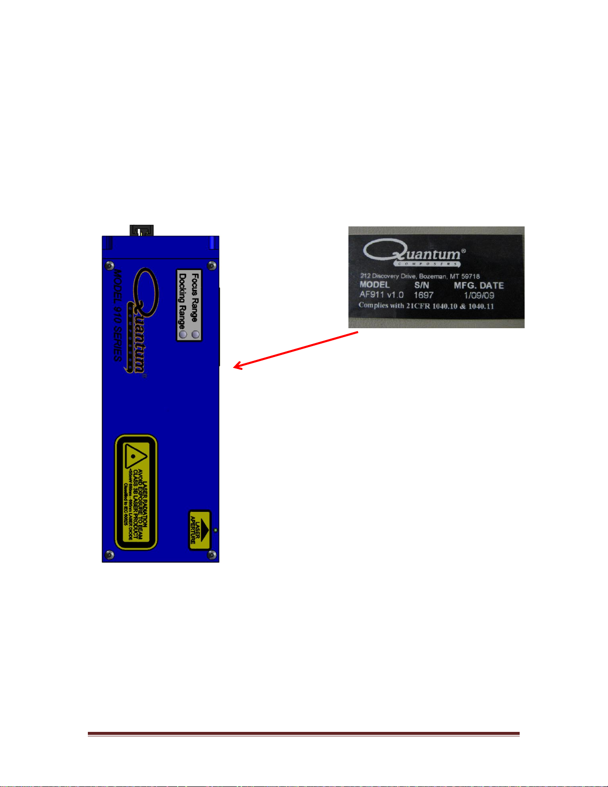
Safety Labels and Locations
The following figures depict the safety, model number, serial number and origination
labels and their locations on the AF910. These labels are installed at the factory and
should not be removed by the user. If for some reason a label is removed, obscured or
damaged in any way, please contact the manufacturer for a replacement.
AF910 Manual Version 1.4 Page 9
Page 10
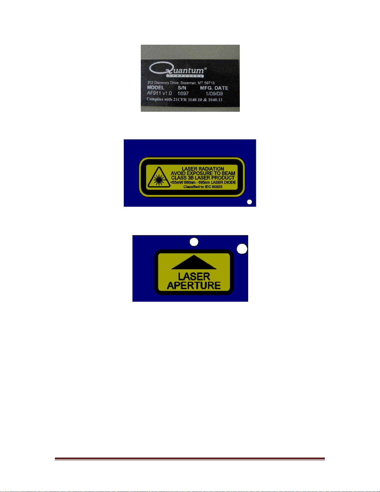
Figure 1 Certification and ID Label
Figure 2 Laser Radiation
Figure 3 Laser Aperture
Page 10 AF910 Manual Version 1.4
Page 11
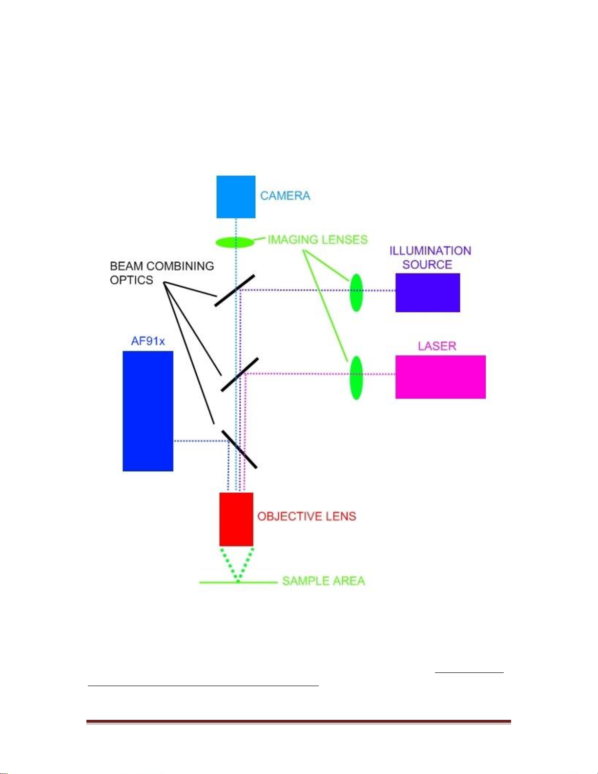
CHAPTER 3 – Installation
The AF91x can be installed on many types of video microscope setups that include the
use of infinity corrected optics. The diagram below shows a typical optical setup
including the AF91x unit.
The AF91x must be installed in the infinity region of the optical path. If using an infinity
corrected objective lens (typically noted by the ∞ symbol), then the unit must be placed
between the objective lens and any other focusing lenses. The AF91x has both metric and
imperial mounting points. Refer to the mechanical diagram for placement. The unit
should be mounted so that it is as stable as possible. A beam combining optic should be
used, preferably on an adjustable mount. If polarizing optics are used, the polarization of
the laser diode is vertical to the mounting surface of the AF91x. Be sure that the
polarization is correct or else the performance of the unit may suffer due to transmission
AF910 Manual Version 1.4 Page 11
Page 12

losses. Once the unit is mounted, then the electrical connections can be made. At the very
least, the unit needs +12VDC power at 300mA and serial (RS232) connections made.
Refer to the electrical connection tables. Once the electrical connections are made and the
unit is powered on, communication can be established by either running the AF91x
software or using an appropriate terminal program such as HyperTerminal. Refer to the
communication section of the manual for details on operating the unit via RS232
connections.
When adding the AF91x to an infinity corrected beam path, the laser diode should be
adjusted so that it enters the objective lens aperture correctly. If it does not enter the
objective lens on axis, then performance may be reduced. It is assumed that some kind of
beam combining optic is used on an adjustable mount. This optic should be adjusted so
that the laser diode beam at the entrance of the objective looks like the following image.
Figure 4 Laser Beam Centering
Be sure that the laser diode does not cross over the centerline of the objective aperture
otherwise performance may be reduced.
Page 12 AF910 Manual Version 1.4
Page 13

CHAPTER 4 – Operating the AF910
Methods of Operation
The AF91x can be operated in various ways. Communication via a serial port is always
necessary to control basic functions and to setup various parameters. The unit has two
methods for controlling or indicating where the focus point is. The first is the analog
output signal which can be monitored to determine when focus has been achieved. The
second is the motor control functions which provide both step and direction outputs to
control a focusing motor.
Software Quick Start
Once the unit is installed on a video system, proper power has been applied and the
communication lines connected, the system can then be run via the communications port.
The included software is meant to be a quick start way of operating the unit. After the
software is installed run it and select the appropriate communications port if necessary. If
the unit is not found on any of the communication ports, double check the connections.
The AF91x software communicates with the unit at the default baud rate of 57,600. Be
sure the communication speed has not been altered. See the command set section for
more details of setting different communication speeds.
Figure 5 Auto Focus Model 91x Software
AF910 Manual Version 1.4 Page 13
Page 14

The unit will then be enabled and its status displayed. You should see that the laser diode
has been enabled. This also means that the analog output is now active. To turn off the
autofocus and thereby disabling the analog output function, deselect the Autofocus
Enable checkbox.
Figure 6 Autofocus Enable
Determine what objective number you would like to assign to the current lens. This is
done via the OB command (OB1, OB2, OB3, etc). For example, a 10x objective lens
could be assigned to OB number 1. All calibration parameters for that particular objective
would be stored as OB1. This can be selected using the included software by selecting a
number from the drop down selector.
Figure 7 Objective Selection
Focus the objective on the target sample by either using an external means or using the
built in motor controller function of the AF91x (if connected and utilized). Once focused
on the target, calibrate the autofocus by issuing the offset (OF) command or using the
software calibrate button.
Figure 8 Objective Offset Calibration
This now calibrates the selected objective to be in focus at that point. Repeat this step for
any other objectives to be used. Remember to change the objective number each time you
change objective lenses so that all the correct calibration parameters are recalled. The
calibration process should only be used if the target sample type changes or alignment of
the system is adjusted.
There are various focus windows that can be adjusted. When using the motor control
ouputs, these windows affect the speed at which the motor will move when outside the
windows. These are described in more detail under the Motor Controller section of the
manual. These windows will also affect the analog output and how it is set. In general,
Page 14 AF910 Manual Version 1.4
Page 15

when outside of the docking range, the motor will move at the high speed and the analog
output will be clamped at the highest level (either positive or negative depending on the
last known direction). When inside the docking range, the motor will slow down to the
slow speed and the analog output will follow the focus level. Once the focus level has hit
the target focus, the motor will not move again until it gets outside of the focus range
window.
Figure 9 Focus Windows
The manual stage controls are accessed by selecting the Move Stage tab. These controls
are enabled only when the Manual Drive Option is set to manual. Use these controls to
absolute and relative movement of the stage. These are described in more detail in the
Motor Controller description section of the manual.
Figure 10 Stage Manual Controls
Manual control of the laser diode intensity is provided for diagnostic and alignment
purposes only and is accessed by selecting the Diode Control Tab. For normal operation
of the autofocus the diode control must be set to Auto Diode Mode. If it is not set to auto
mode, then the system cannot dynamically adjust the diode intensity, which may affect
performance.
AF910 Manual Version 1.4 Page 15
Page 16

Figure 11 Laser Diode Controls
The autofocus data section of the software is used to view the current analog output based
on position as well as the sensor output if desired. The sensor output data should be used
only for diagnostic purposes and as a check to see that you are getting a strong signal on
the sensor. Pressing the “Single Sensor Capture” button will grab one frame of the sensor
and display it on the plot. A reasonable signal when in focus on the sample is shown in
the image below. Selecting “Continuous Data Scan” will constantly scan the sensor data.
This should only be used for diagnostics and alignment purposes. The enable polling
option will enable/disable polling any status from the autofocus. Normally, this can be
left in the selected mode.
Figure 12 Autofocus Data
Selecting the Comm Terminal Tab provides the user with the ability to send commands
directly to the autofocus controller. The commands described in the command set section
could be entered using this tab.
Page 16 AF910 Manual Version 1.4
Page 17

Figure 13 Communication Terminal
Analog and Digital I/O
The AF91x offers several I/O signals to help control and determine status of the unit.
Used in conjunction with the RS232 commands, these can offer a direct method of
determining distance to focus. The pins these signals are available on are listed in the
electrical connection section. The motor controller specific signals are described under
the motor controller section of the manual.
In Range. This signal is an active low output (open collector) that indicates when the
sample is inside the docking range window or inside the linear range. There is also an
LED indicator on the outside of the unit for this status.
In Focus. This signal is an active low output (open collector) that indicates when the
sample is inside the focus range window. When this status is active, the motor controller
function will be stopped. There is also an LED indicator on the outside of the unit for this
status.
EMO (Emergency Machine Off). This is an active high input that will stop all functions
of the autofocus unit when activated. The analog output will be zeroed and the motor
control functions will be stopped.
Laser Disable. This is an active low input (pull to 0V to activate) that will turn off the
laser diode and temporarily stop the motor control. Once the input is activated again (or
released), the laser diode will turn back on. The motor control functions (step) will stop
when this is disabled and must be manually enabled again. The analog output will
automatically start updating when released.
AF Status. This is an active high output that indicates when the autofocus has been
enabled.
Analog Output. This signal outputs a ±10V signal based on the distance from the
calibrated focus point. An output of zero volts will indicate that you are in focus. When
the output “clamps” at the maximum of ±10V, the unit is indicating you are outside of the
AF910 Manual Version 1.4 Page 17
Page 18

docking range, which is also outside of the linear range. The sign of the signal can be
used as a method to determine the direction of focus. There is a method to scale the
output when inside of the linear range. This is the analog scalar (AS) command described
in the command set section.
Figure 14 Analog Output
Motor Controller Description and Setup
The AF91x includes built in motor control functions that can directly drive most motor
driver modules that accept motor step and direction signals. This eliminates the need for a
separate motor controller module to process the analog output signal and convert to a step
and direction. The motor control functions consist of the following features:
- Motor step signal.
- Motor direction signal.
- Two limit switch inputs.
- Homing function.
- 32 bit position counter (± 2,147,483,647 counts).
- Configurable limit switch polarities.
- Configurable motor directions.
Page 18 AF910 Manual Version 1.4
Page 19

- Acceleration function.
- Adjustable step rates up to 80KHz.
- Two speeds for inside and outside of docking range.
- Algorithms for filtering out features that may cause false focus conditions.
- Focus loop update rate of 1KHz.
- Objective offset feature to allow for varying focal planes when switching
lenses.
Figure 11 below shows the typical connections made when using the AF91x for motor
control. Figure 12 shows the typical connections needed for other autofocus units.
Typically an additional motor controller is needed as well as some kind of analog to
digital converter module. Associated software must also be written to tie everything
together.
Figure 15 (AF91x Motor Control)
Figure 16 (Typical AutoFocus Motor Control)
Motor Controller Connections:
Refer to the electrical connection tables for pin numbering and types of connectors to use.
The step and direction signals should be connected to the inputs of the motor driver being
used. The step and direction outputs are TTL levels that can source up to 50mA. The step
output is a pulsed signal with period that is adjustable and a pulse width that is typically
5us. The two limit switch inputs can be connected to any type of limit switch that
AF910 Manual Version 1.4 Page 19
Page 20

provides either a TTL or an open collector type output. The limit switches can be
configured to be either active high or active low. Refer to the serial command set for a
description on how to configure the limit switch input polarities.
Setup and Control:
There are two modes of operation for the motor controller: manual and automatic. When
in manual mode, the motor control is initiated by the host and when in automatic mode,
the motor control is initiated by the sensor. When in automatic mode, the sensor will
control the speeds and direction of the motor as well as starting and stopping movement.
This allows for the unit to maintain focus without user intervention. Many of these
functions are also describe in the command set section.
- Motor Speed. There are two speeds available, high and low. When in manual
mode, the last set speed whether it is high or low becomes the active speed.
When in auto mode, the system determines the speed to be use based on the
distance away from the target focus. The speed command (SP) is used to set
the high and low speeds of the unit.
Figure 17 Motor High/Low Speeds
Initial Speed. This is the initial or starting speed that the motor will begin to move at.
This must be adjusted according to the dynamics of the motor controller and the type
of motor or stage being used. If set to fast, the motor may immediately stall, if set to
low, the motor may take too long to get up to the target speed (high or low). The IS
command is used to set this parameter. The motor will dynamically accelerate the
speed from the initial speed to the high or low target speed.
Figure 18 Motor Initial Speed
- Home Speed. This is the speed at which the motor will move when the home
sequence is initiated. This speed should be set such that the motor can
accurately detect the limit switch without any possibility of over-running it.
This is set by using the HS command.
Page 20 AF910 Manual Version 1.4
Page 21

Figure 19 Motor Home Speed
- Limit Switches. The limit switches will stop motor movement when activated.
They also serve as a reference, or home position when using the motor home
function. The limit switches can be configured as active high or active low.
The limits sensor inputs are internally pulled high to a 5V level. The default
setting is active low. The motor configuration register contains the option for
active high or active low limits. See the MC command for details. The limits
can also be disabled if needed. The LD command performs this function. By
default, the limits are enabled. The limits can also be swapped in function by
setting the appropriate option in the motor configuration register.
Figure 20 Limit Switch Setup
- Homing Function. The system can automatically perform a home sequence so
that the position counter can be initialized to a known position (the limit
switch). When initiated by issuing the HM command, the motor will begin to
move at the home speed set by the HS command towards the “A” or positive
limit switch. Once this limit is reached, the motor will slowly back off of the
limit to accurately determine the limit position and zero the step counter. The
motor will then move to a post home position which is set by using the PH
command. The limit that the home sequence moves to can also be reversed by
setting the option in the motor configuration register.
Figure 21 Home Function
Figure 22 Reverse Homing
AF910 Manual Version 1.4 Page 21
Page 22

- Step Counter. The system uses an internal 32 bit position counter to keep track
of motor steps. This allows for step counts of ± 2,147,483,647. The position
counter is initialized when a homing sequence occurs or can be manually
zeroed as well. The SC command is used for both querying and resetting the
counter.
Figure 23 Step Counter
- Movement Functions. There are three ways to command the motor to move
when in manual movement mode: continuous, absolute and relative. A
continuous movement will continue to move unit a stop command is received.
It is up to the user to stop the motor when desired in this case. A CM
command is used to move continuously positive or continuously negative (jog
function). A ST command will stop movement. An absolute command will
move to the position given. This can be a positive or negative position. The
controller will determine the direction and number of steps to move until the
commanded absolute position is reached. A relative command will move the
number of steps given relative to the current step counter. The MV command
is also used for this function with the addition of the “+” or “-“ prefix to
indicated whether or not this is a positive or negative relative step command.
Figure 24 Motor Movements
- Automatic Mode. This mode will enable the motor to move based on the
position calculations from the sensor. The motor will automatically move and
determine direction in order to maintain focus on the sample. The AM
command is used to enable and disable this function. When in automatic mode
all manual movement commands will be ignored and responded to by
returning a “?3” error.
Figure 25 Motor Drive Mode
Page 22 AF910 Manual Version 1.4
Page 23

- Step Offset Function. This function will allow the motor to move any offset
distance when switching objective lenses. Since objectives may have different
focal lengths, this method will move the stage (using motor steps) a set
amount when switching lenses. The change disable command (CD) allows for
the switching of objectives and positioning the focus stage into a nominal
position before re-enabling the auto focus. Once this command is issued, the
auto focus will be disabled and the stage positioned into a nominal focus for
the next objective. This eliminates the need to manually adjust the focus stage
before re-enabling the auto focus if there is a variation in the focal lengths of
the objectives being used. Each objective number will have an associated
focus stage offset motor count. This will assure that the focus stage is
positioned within the auto focus’s capture range before it is enabled. Refer to
the command set section for detailed usage of the commands.
Figure 26
Procedure:
1. Select an objective as the reference objective. This will be the objective that
will have a zero step offset value to it (CO value).
2. Use the OB command to select the proper objective number. Example: select
OB 1 for the reference objective.
3. Focus the reference objective by moving the focus stage up and down using
the motor control commands.
4. Using the CO command, enter a value of 0 for the change offset. Take note of
the motor step position using the SC? command. Write this number down as
the reference position. This reference position will be used to calculate all the
other objective offsets.
5. Select the next objective to calibrate the step offset for. Change the objective
by using the OB command. Example: select OB 2 for the next objective.
6. Focus the objective using the motor control commands and take note of the
motor step position using the SC? command.
7. Subtract the reference objective motor step position from the new objective
focus position (New Position – Reference Obj Position = CO value). This will
be the value you enter using the CO command. This may be a positive or
negative offset depending on if the focus for the new objective was higher or
lower than the reference objective.
8. Repeat steps 5-7 for the next objectives. Be sure the change the objective
number each time using the OB command and recording the new objective
position and calculating the motor step difference between it and the original
reference objective.
AF910 Manual Version 1.4 Page 23
Page 24

Figure 27
Example (using picture above). Using this example, the home or zero position is above
focus, so raising objectives above sample will decrease motor counts, while lowering
objectives closer to sample will increase counts.
- Objective #1 is selected as the reference objective. When in focus its
motor step count position is 25,000.
- The remaining objectives have focus positions (motor steps) as follows:
o Objective #2 = 34,000.
o Objective #3 = 36,500.
o Objective #4 = 15,400.
o Objective #5 = 20,125.
o Objective #6 = 42,000.
- Each objective offset can be calculated like this:
o Objective #1 offset is zero since it is the reference objective. Any
objective number can be selected as the reference.
o Objective #2 offset: 34,000 – 25,000 = 9000 (or hex h2328).
o Objective #3 offset: 36,500 – 25,000 = 11,500 (h2CEC).
o Objective #4 offset: 15,400 – 25,000 = -9600 (negative, use 2’s
compliment, so hDA80).
o Objective #5 offset: 20,125 – 25,000 = -4875 (hECF5).
o Objective #6 offset: 42,000 – 25,000 = 17,000 (h4268).
Page 24 AF910 Manual Version 1.4
Page 25

- Focus Windows. Various windows can be adjusted to improve the
Pin No.
Name
Description
1
DCD
Data Carrier Detect †
2
Rx
RS232 Receive
3
Tx
RS232 Transmit
4
DTR
Data Terminal Ready †
5
Gnd
Ground
6
DSR
Data Set Ready †
7
RTS
Request to Send †
8
CTS
Clear to Send †
9
RI
Ring Indicator †
† denotes signal not used by the autofocus
performance of the motor control loop when approaching and stopping at the
target focus position. There are three (3) windows that can be adjusted that
affect how the motor speeds are utilized when in automatic mode.
o Focus Target Window. This is the absolute focus target variation. A ±
range that the focus signal can be within before the In Target Focus
condition is set and the motor movement is stopped. The FT command is
used to adjust this value.
o Focus Range Window. A ± range that the focus signal can be within
before the In Focus Range condition is set. Motor movement will not be
started until the focus signal level is greater than this value. The FR
command is used to adjust this value.
o Docking Range Window. A ± range that the signal can be within before
the Docking Range condition is set. When the focus signal is within this
window, the stage speed will be reduced to the slower speed. When
outside of this window, the high motor speed will be used. This allows the
motor to slow down when approaching the target focus so that
overshooting does not occur. The DR command is used to adjust this
value.
Figure 28 Focus Windows
Communicating with the AF910
The AF91x communicates via a standard RS232 connection. The default communication
settings are 57,600 baud, 8 data bits, even parity and 1 stop bit (57600, 8, E, 1). A typical
serial port pin out is shown below. Only the Rx, Tx and Gnd are used to communicate
with the AF91x. The included software can be used to operate the unit over the serial port
at the default baud rate of 57,600.
Typical PC Serial Port (DB9)
AF910 Manual Version 1.4 Page 25
Page 26

Command Set
Field
Description
Prefix
Single semicolon character ";", must precede all commands. All devices
will reset their command input buffer when the prefix is received.
Address
2 ASCII characters. Each device has a unique address which is
programmed into its firmware. See the table below for a list of addresses.
Delimiter
Single colon character “:”, must follow device address.
Command
String
Commands are specific to each device -- see the following sections for
the commands that each device supports.
Parameters
(optional field) Some commands may have parameters which
immediately follow the command string. Multiple parameters are
separated by commas.
Terminator
ASCII carriage return character (decimal value 13). The receiving device
does not process any commands until the terminator is received.
Address
Device
AF
Auto Focus Controller
Device Command Format
All commands use ASCII characters and are composed of the following fields:
<Prefix><Address>< Delimiter><Command String>[Parameters]<Terminator>
Device Address
Command Types
There are two types of commands -- those that set a value or initiate an actions (control
commands), and those that request information (query commands). Each device must
respond in the proper manner to each type of command.
Control Commands
A device must always parse a control command and return a response immediately.
If the command is a recognized command and the parameter is valid, then the device
returns an "OK<CR>". (<CR> = ASCII carriage return, decimal value 13).
If the command is not recognized by the device, then it responds with "?1<CR>
If the command is recognized, but the parameter value is missing or invalid, then the
device responds with a "?2<CR>".
If the command is recognized, but the parameter is out of range, then the device
responds with a “?3<CR>”.
Page 26 AF910 Manual Version 1.4
Page 27

If a control command is received while the device is in the midst of executing a previous
Command
Description
VN
Return firmware version number
RS
Reset, return to power-up defaults.
Command
Description
*RS
Reset, return to power-up defaults. All
devices
command, and the commands are mutually exclusive (cannot be executed in parallel),
then the previous command is aborted and the new one executed. It is up to the host
controller (the PC) to poll the device and make sure the previous command is finished, if
that is the needed.
Query Commands
Query commands return a value to the PC as soon as the command is parsed and
executed. The value returned will depend on the command. The response is always
terminated with a <CR>. If a query command is not recognized by the device, then a "?0"
is returned.
Common Commands
All devices are required to support some common commands as part of their command
set. Those commands are:
Global Commands
By using a special prefix (the * character), it is possible to send a command to all the
devices at once. When a global command is sent, no device will send a response.
Auto Focus Command Set
AE # Autofocus Enable. Enables or disables the auto focus process. A
“1” enables auto focus (not the motor) and a “0” disables it. A “?”
will return the current state.
AM #, AM? Auto Motor Enable. Enables or disables the automatic movement
of the motor to find the focus. A “1” enables it (default) and a “0”
disables it. A “?” will return the current state.
AS ####, AS? Analog Scalar. This parameter will effectively scale the amplitude
of the ±10V analog output when inside of the docking range. The
default scalar is 1. The higher the number, the steeper the slope
will be. Values are from 0x0001 to 0x000A. A “?” will return the
current value. This is an objective specific parameter.
AF910 Manual Version 1.4 Page 27
Page 28

BR?, BR # Baud Rate. Selects between two different RS-232 baud rates. A
“1” selects the high baud rate of 57600 with even parity and 8 data
bits and 1stop bit. A “0” selects a low baud rate of 9600 no parity
and 8 data bits and 1stop bit. The default is the high baud rate. This
command will executed after a power cycle of the unit.
CD #, CD? Change and Disable. This command will disable the auto focus,
change the objective to the given parameter, move the stage to a
nominal focus position and evoke the offset based on the CO
command for the given objective, then re-enable the auto focus.
Each objective may have a specific offset value associated with it
for calibration purposes. Values are from 0 to 7. A “?” will return
the current objective number being used.
CE #, CE? Change Enable. A “1” enables the auto focus, but first checks to
see if the data is valid. If the data is not valid, then a “?4” will be
returned. If the data is valid, the auto focus will be enabled as well
as the motor movement. A “0” will disable it. A “?” will return the
current value.
CM ± Continuous Move. When in manual motor mode, issuing a
continuous move will start moving the motor in the commanded
direction until either a limit is hit or a stop (ST) command is
received.
CO ####, CO? Change Offset. A ± motor step offset value that allows for optimal
positioning between objective changes. This value will be an offset
from some reference position such as the lowest magnification
objective. Values range from 0x7FFF (+32767) to 0x8001(-
32767). A 2’s compliment method is utilized to represent
maximum decimal values of ±32767. The parameter is a 4 digit
hex value. A “?” will return the current value.
DR ####, DR? Docking Range. A ± range that the signal can be within before the
Docking Range bit is set. When the focus is within this window,
the stage speed will be reduced to the slower speed. Values are
from 0x0000 to 0xFFFF. A “?” will return the current value.
DS #, DS? Diode Select. This selects the laser diode source for the currently
selected objective. Each diode (in a dual diode system) is focused
at a different plane. This will help the focusing process when a
specific objective may have a different focal plane than the other.
A “0” will enable diode 1 only, and a “1” will enable diode 2 only.
A “?” will return the current diode selection. Default value is “0”.
EC #, EC? Echo. A “1” turns communication echoing on and a “0” turns it
off. A “?” will return the current state.
Page 28 AF910 Manual Version 1.4
Page 29

FL? Focus Level. Returns the current focus level value from 0x0FFF to
7 6 5 4 3 2 1
0
Reserved
Low Speed
Mode
Auto Reset
Enable
Limits
Disabled
Active
High
Limits
Reverse
Homing
Reverse
Motor
Reverse
Limits
0x0000. A value of 0x07FF is in focus or 0V output from the ±10V
analog output.
FR ####, FR? Focus Range. A ± range that the focus signal can be within before
the In Focus Range bit is set. Once the target focus has been found,
the motor will not move again until it gets outside the focus range.
Values are from 0x0000 to 0xFFFF. A “?” will return the current
value.
FT ####, FT? Focus Target. This is the absolute focus target variation. A ±
range that the focus signal can be within before the In Target Focus
bit is set. When within this target range, motor movement will be
stopped. Values are from 0x0000 to 0xFFFF. A “?” will return the
current value.
HM Home. This command will home the motor to a limit switch and
reset the step counter to zero upon reaching the limit. After the step
counter is reset the motor will proceed to the Post Home position.
The limit used in the homing will depend on the motor options set;
these settings can be verified using the Motor Config command
listed below.
HS ####, HS? Home Speed. This is the speed at which the motor will move
when homing (HM). Motor speeds are calculated the same as the
SP command. A “?” will return the current value.
IS ####, IS? Initial Speed. This sets the initial or starting speed of the motor.
The motor will start moving using this speed and then ramp up to
the target maximum speed. See the SP command for details in
calculating the parameter. Values are from 0x0000 to 0x4D58. A
“?” will return the current value.
LD #, LD? Limit Switch Disable. This will disable the motor limit switches.
If disabled, the motor will not be stopped when a limit is tripped. A
“1” disables the limits and a “0” will re-enable them. A “?” will
return the current state.
Note: This command will not affect the limits when a home command is
used.
MC?, MC ## Motor Config. This command will set the motor configuration
bits. These parameters are stored in EE Prom and recalled on
power up or reset.
AF910 Manual Version 1.4 Page 29
Page 30

MS Motor Status. Returns the current motor status bytes.
7 6 5 4 3 2 1
0
Reserved
Reserved
Homing
Moving
Direction
Motor
Enabled
Limit B
Limit A
15
14
13
12
11
10 9 8
Ignore
Focus Step
Decelerate
At Target
Speed
Focus
Positioning
Back Off
Continuous
Move
SC
Query
Motor
High
Speed
MV ±########,
MV ########
Move Command. Moves the motor either a specified number of
steps relative to current position or absolute relative to zero. Values
are 32 bit hex. A “-“ moves negative the number of specified steps
and a “+” moves positive the number of specified steps relative to
the current position. No + or – will move the motor to the specified
absolute position relative to zero.
OB #, OB? Objective. This command sets the objective number to be used.
Each objective may have a specific offset value associated with it
for calibration purposes. Values are from 0 to 7. A “?” will return
the current objective number being used.
OF !, OF? Objective Offset Value. This command sets the desired objective
offset value for the currently selected objective (OB command). A
“?” will return the offset value for the currently selected objective.
Using the “!” parameter will start auto calibration routine to set the
offset for you. This is the recommended method of calibrating the
offset. To use this parameter the system should be focused on the
material, and the desired bin should be selected, then send the “!”
parameter to store the calculated offset.
PH ########, PH? Post Home. This command sets the number of steps that the motor
will move after detecting the limit switch when the home
command has been received. See the HM command for the
sequence of operation. Values are from 0x00000000 to
0xFFFFFFFF. A “?” will return the current value.
RS Reset. This command will reset the system to the initial power on
state.
SC, SC - Step Count. This command will return the current step count
position. Adding a “-“ will zero out the position counter. The value
returned will be a 32 bit hex value. Values can range from
±2,147,483,648. A 2’s compliment method will indicate negative
step counts.
Page 30 AF910 Manual Version 1.4
Page 31

SO ####, SO? Sensor Offset. This is an objective specific offset that should be
SP?, SP L?,
SP L ####
SP H?, SP H ####
Speed. Sets the motor clock speed output. A “?” will return the
active speed. The last speed changed is by default the active speed
and the motor will move at that speed if no other commands are
altered before the move command is sent. Step rates are 16 bit hex
values based on the following decimal calculations:
Rate = 20,000,000/(65,536-Value)
Value = 65,536 – (20,000,000/Rate)
The maximum step rate available is ~80KHz or a decimal value of
65300. Rates above 10KHz may have an error of ~10%. A “H”
parameter sets the high speed value that is used when the focus is
outside of the docking area. A “L” parameter sets the low speed
which is used once focus is inside the docking range.
7 6 5 4 3 2 1
0
Signal
Power Too
High
Signal
Power Too
Low
High
Sensor
Gain
Invalid
Data
Auto
Focus
Enabled
In
Docking
Range
In Focus
Range
In Focus
15
14
13
12
11
10 9 8
Area
Invalid
Power
Invalid
CoM
Invalid
Peak
Invalid
Intensity
Error
EMO
Status
Laser
Disabled
Auto
Motor
set before data is collected off the sensor array. Each value is a
multiple of 8. The default is 2, which means that 2 x 8 = 16 pixels
of the linear array will be ignored before data is captured. This
command will allow the system to ignore a section of the array
data when determining the focus position. Values are from 0x0000
to 0x0020. A “?” will return the current offset value.
SP M Speed Maximum. This command returns the current max speed
for the system. Values will range from 0x0000 to 0xFFFF.
SS System Status. Returns two bytes that indicate the status of
various system states.
ST Stop. Stops motor movement. This will stop the motor and take it
out of auto motor mode if enabled.
VN Version Number. Returns the firmware revision number as a 3-
digit number followed by a release Alpha character in the format
“m.nnr”, where m = major version, n = minor version and r is the
release build. Ex: 1.22A.
AF910 Manual Version 1.4 Page 31
Page 32

CHAPTER 7 – Maintenance
The AF91x does not have any user serviceable components. Any need for maintenance
should be done by an authorized service representative. Please contact the factory for
details. The system should be kept free of dust and debris.
Page 32 AF910 Manual Version 1.4
Page 33

CHAPTER 9 – Trouble Shooting Guide
Problem
Solution
Indicated focus does not match
objective focus
- The offset has not been properly
calibrated. Refer to the OF
command.
- Laser diode alignment is not
properly aligned to objective
entrance aperture. Refer to the setup
section.
Cannot communicate with unit
- Be sure that the communication
settings on the host computer are
set to 57,600, E, 8, 1.
- Check to see if the baud rate has
been switched to 9600, N, 8, 1. See
the BR command.
The stage motor oscillates around the
focus point.
- Increase the In Focus window. See
the FR command.
- Slow down the slow speed setting.
The motor may be moving too fast.
See the SP L command.
AF910 Manual Version 1.4 Page 33
Page 34

CHAPTER 10 – Appendixes
Objective
2x
5x
10x
20x
50x
100x
Focus Repeatability (um)
+/- 6.0
+/-2.5
+/- 0.5
+/- 0.4
+/- 0.3
+/- 0.2
Focus Accuracy (um)
+/- 20.0
+/- 5.0
+/- 1.0
+/- 0.8
+/- 0.5
+/- 0.3
Resolution (um)
2.00
1.00
0.50
0.20
0.10
0.06
Linear Range (um)
+/- 500
+/- 500
+/- 250
+/- 100
+/- 40
+/- 15
Capture Range (um)
+/- 5000
+/- 3000
+/- 1500
+/- 600
+/- 240
+/- 40
General
Analog update rate
1.2 kHz
Step control update rate
1.2 kHz
Max step rate
50 kHz
Wavelength
685 nm
Power consumption
+12 VDC/500ma
Performance Specifications
Page 34 AF910 Manual Version 1.4
Page 35

Pin
Name
Type
Description
1
+12VDC
Power
Positive supply voltage (350mA)
2
GND
Power
Ground
3
+12VDC
Power
Positive supply voltage (350mA)
4
GND
Power
Ground
5
N/C
N/A
No connection
6
N/C
N/A
No connection
7
N/C
N/A
No connection
8
N/C
N/A
No connection
9
GND
Power
Ground
Mechanical Dimensions
Electrical Specifications and Connections
The AF91x requires 12 VDC power at 300mA to operate. It is important that 12 VDC
power not vary by more than +/- 200mV or damage to the unit may occur.
Main Sensor Connection
Connector Type(s): Molex Milli-Grid (ribbon cable type), # 87568-3063 or Molex MilliGrid (crimp style), #51110-3051 and contacts #50394-8100.
AF910 Manual Version 1.4 Page 35
Page 36

10
LIMIT B
Input
TTL active low input. Negative direction limit switch
input (B)
11
LIMIT A
Input
TTL active low input. Positive direction limit switch
input (A)
12
RESERVED
N/A
Reserved – Do not connect
13
RESERVED
N/A
Reserved – Do not connect
14
Rx IN
Input
RS232 receive
15
Tx OUT
Output
RS232 transmit
16
GND
Power
Ground
17
RESERVED
N/A
Reserved – Do not connect
18
RESERVED
N/A
Reserved – Do not connect
19
RESERVED
N/A
Reserved – Do not connect
20
+5VDC
Output
Reference output. 50mA max.
21
/LASER DISABLE
Input
Active low input to disable laser diode
22
RESERVED
N/A
Reserved – Do not connect
23
AF STATUS
Output
TTL active high output. High level indicates autofocus
is enabled
24
EMO
Input
TTL active high input. Stops autofocus and motor
movement
25
GND
Power
Ground
26
/IN RANGE
Output
Open collector output. Active low when signal is in
range
27
/IN FOCUS
Output
Open collector output. Active low when signal is in
focus
28
ANALOG OUT
Output
+/-10V analog output corresponding to focus position.
Zero volts indicates in focus
29
STEP
Output
TTL signal output for motor step
30
DIRECTION
Output
TTL signal output for motor direction
Adapter Board # 300001-018 Connections
Pin
Name
Type
Description
1
GND
Power
Ground
2
N/C
N/A
No connection
3
+12VDC
Power
Positive supply voltage (350mA)
4
+12VDC
Power
Positive supply voltage (350mA)
5
GND
Power
Ground
6
GND
Power
Ground
7
Rx IN
Input
RS232 receive
8
Tx OUT
Output
RS232 transmit
9
N/C
N/A
No connection
10
GND
Power
Ground
11
N/C
N/A
No connection
12
N/C
N/A
No connection
Connector Types: Hirose DF11 Series, # DF11-12DS-2C.
Sockets: # DF11-2428SC (24-28 AWG).
Power and Communication
Page 36 AF910 Manual Version 1.4
Page 37

Pin
Name
Type
Description
1
ANALOG OUT
Output
+/-10V analog output corresponding to focus position.
Zero volts indicates in focus
2
/IN RANGE
Output
Open collector output. Active low when signal is in
range
3
/IN FOCUS
Output
Open collector output. Active low when signal is in
focus
4
AF STATUS
Output
TTL active high output. High level indicates autofocus
is enabled
5
GND
Power
Ground
6
EMO
Input
TTL active high input. Stops autofocus and motor
movement
7
/LASER DISABLE
Input
Active low input to disable laser diode
8
LIMIT A
Input
TTL active low input. Positive direction limit switch
input (A)
9
LIMIT B
Input
TTL active low input. Negative direction limit switch
input (B)
10
RESERVED
N/A
Reserved – Do not connect
11
GND
Power
Ground
12
STEP
Output
TTL signal output for motor step
13
DIRECTION
Output
TTL signal output for motor direction
14
RESERVED
N/A
Reserved – Do not connect
Connector Types: Hirose DF11 Series, # DF11-14DS-2C.
Sockets: # DF11-2428SC (24-28 AWG).
Signals
AF910 Manual Version 1.4 Page 37
Page 38

Adapter Board # 300001-026 Connections (Opto-Isolated)
Pin
Name
Type
Description
1
GND
Power
Ground
2
N/C
N/A
No connection
3
+12VDC
Power
Positive supply voltage (350mA)
4
+12VDC
Power
Positive supply voltage (350mA)
5
GND
Power
Ground
6
GND
Power
Ground
7
Rx IN
Input
RS232 receive
8
Tx OUT
Output
RS232 transmit
9
N/C
N/A
No connection
10
GND
Power
Ground
11
N/C
N/A
No connection
12
N/C
N/A
No connection
Pin
Name
Type
Description
1
ANALOG OUT
Output
+/-10V analog output corresponding to focus position.
Zero volts indicates in focus. Not opto-isolated.
2
/IN RANGE
Output
Open collector output. Active low when signal is in
range
3
/IN FOCUS
Output
Open collector output. Active low when signal is in
focus
4
AF STATUS
Output
TTL active high output. High level indicates autofocus
is enabled
5
GND
Power
Ground
6
EMO
Input
TTL active high input. Stops autofocus and motor
movement
7
/LASER DISABLE
Input
Active low input to disable laser diode
8
LIMIT A
Input
TTL active low input. Positive direction limit switch
input (A)
9
LIMIT B
Input
TTL active low input. Negative direction limit switch
input (B)
10
RESERVED
N/A
Reserved – Do not connect
11
GND
Power
Ground
12
STEP
Output
Buffered TTL signal output for motor step. Not optoisolated.
13
DIRECTION
Output
Buffered TTL signal output for motor direction. Not
opto-isolated.
14
+24V External
Opto Power
+24V from external source to power opto-isolators.
Connector Types: Hirose DF11 Series, # DF11-12DS-2C.
Sockets: # DF11-2428SC (24-28 AWG).
Power and Communication
Connector Types: Hirose DF11 Series, # DF11-14DS-2C.
Sockets: # DF11-2428SC (24-28 AWG).
Opto-Isolated Signals
Page 38 AF910 Manual Version 1.4
Page 39

CHAPTER 11 – Customer Service
Warranty
The manufacturer warrants the AF910 it produces to be free from defects in materials and
workmanship for one year following the date of shipment. This warranty is limited to the
original purchaser of the laser and is not transferable.
During the one year warranty, the manufacturer will repair or replace, at option, any
defective products or parts at no additional charge. This is provided that the product is
returned, shipping prepaid, to the manufacturer. All replaced parts and products become
the property of the manufacturer.
This warranty does not extend to any unit which has been damaged as a result of
accident, misuse, abuse (such as use of incorrect input voltages, improper or insufficient
ventilation, failure to follow the operating instructions provided by the manufacturer, or
other contingencies beyond our control) or as a result of service or modification by
anyone other than the manufacturer.
Feedback
We welcome your feedback in regard to the use and performance of our products.
Product improvements and refinements come about from these contact and continually
improve our product reliability, performance and customer satisfaction.
AF910 Manual Version 1.4 Page 39
 Loading...