

Page 1

™
ADIC Management Console
4.4
User’s Guide
Page 2

Scalar i2000 ADIC Management Console User’s Guide, 6-00064-08, March 2007, Made in USA.
Quantum Corporation provides this publication “as is” without warranty of any kind, either express or implied, including
but not limited to the implied warranties of merchantability or fitness for a particular purpose. Quantum Corporation
may revise this publication from time to time without notice.
COPYRIGHT STATEMENT
Copyright 2007 by Quantum Corporation. All rights reserved.
Your right to copy this manual is limited by copyright law. Making copies or adaptations without prior written
authorization of Quantum Corporation is prohibited by law and constitutes a punishable violation of the law.
TRADEMARK STATEMENT
Quantum, DLT, DLTtape, the Quantum logo, and the DLTtape logo are all registered trademarks of Quantum
Corporation.
SDLT and Super DLTtape are trademarks of Quantum Corporation.
Published: March 2007 Document Number: 6-00064-08
Page 3

Contents
1 About This Guide and Your Product 1
Explanation of Symbols and Notes . . . . . . . . . . . . . . . . . . . . . . . . . . . . . . . . . . . . . . . . . . . . . . . . . . . . . 1
Other Documents you Might Need . . . . . . . . . . . . . . . . . . . . . . . . . . . . . . . . . . . . . . . . . . . . . . . . . . . . . 1
Getting More Information or Help . . . . . . . . . . . . . . . . . . . . . . . . . . . . . . . . . . . . . . . . . . . . . . . . . . . . . . 2
2 Description 3
ADIC Management Console Functionality. . . . . . . . . . . . . . . . . . . . . . . . . . . . . . . . . . . . . . . . . . . . . . . . 4
Using the SAN Client. . . . . . . . . . . . . . . . . . . . . . . . . . . . . . . . . . . . . . . . . . . . . . . . . . . . . . . . . . . . . 4
Using a Library Management Client . . . . . . . . . . . . . . . . . . . . . . . . . . . . . . . . . . . . . . . . . . . . . . . . . 4
ADIC Management Console Features. . . . . . . . . . . . . . . . . . . . . . . . . . . . . . . . . . . . . . . . . . . . . . . . . . . 4
Event Logging . . . . . . . . . . . . . . . . . . . . . . . . . . . . . . . . . . . . . . . . . . . . . . . . . . . . . . . . . . . . . . . . . . 4
Reports . . . . . . . . . . . . . . . . . . . . . . . . . . . . . . . . . . . . . . . . . . . . . . . . . . . . . . . . . . . . . . . . . . . . . . . 4
Heartbeat. . . . . . . . . . . . . . . . . . . . . . . . . . . . . . . . . . . . . . . . . . . . . . . . . . . . . . . . . . . . . . . . . . . . . . 5
Health Checks . . . . . . . . . . . . . . . . . . . . . . . . . . . . . . . . . . . . . . . . . . . . . . . . . . . . . . . . . . . . . . . . . . 5
Channel Zoning . . . . . . . . . . . . . . . . . . . . . . . . . . . . . . . . . . . . . . . . . . . . . . . . . . . . . . . . . . . . . . . . . 5
Data Mover . . . . . . . . . . . . . . . . . . . . . . . . . . . . . . . . . . . . . . . . . . . . . . . . . . . . . . . . . . . . . . . . . . . . 5
Scalar® Firewall Manager / Virtual Private SAN®. . . . . . . . . . . . . . . . . . . . . . . . . . . . . . . . . . . . . . . 5
extended VPS® . . . . . . . . . . . . . . . . . . . . . . . . . . . . . . . . . . . . . . . . . . . . . . . . . . . . . . . . . . . . . . . . . 5
Virtual Private Map . . . . . . . . . . . . . . . . . . . . . . . . . . . . . . . . . . . . . . . . . . . . . . . . . . . . . . . . . . . . . . 5
SNMP . . . . . . . . . . . . . . . . . . . . . . . . . . . . . . . . . . . . . . . . . . . . . . . . . . . . . . . . . . . . . . . . . . . . . . . . 6
Library RMU Support . . . . . . . . . . . . . . . . . . . . . . . . . . . . . . . . . . . . . . . . . . . . . . . . . . . . . . . . . . . . . 6
Security . . . . . . . . . . . . . . . . . . . . . . . . . . . . . . . . . . . . . . . . . . . . . . . . . . . . . . . . . . . . . . . . . . . . . . . 6
Network Discovery. . . . . . . . . . . . . . . . . . . . . . . . . . . . . . . . . . . . . . . . . . . . . . . . . . . . . . . . . . . . . . . 6
Configuration Options . . . . . . . . . . . . . . . . . . . . . . . . . . . . . . . . . . . . . . . . . . . . . . . . . . . . . . . . . . . . 6
Updating Firmware . . . . . . . . . . . . . . . . . . . . . . . . . . . . . . . . . . . . . . . . . . . . . . . . . . . . . . . . . . . . . . 6
Obtaining Drive Dumps . . . . . . . . . . . . . . . . . . . . . . . . . . . . . . . . . . . . . . . . . . . . . . . . . . . . . . . . . . . 6
Command Flow Logging . . . . . . . . . . . . . . . . . . . . . . . . . . . . . . . . . . . . . . . . . . . . . . . . . . . . . . . . . . 6
3 Getting Started 7
Installation Requirements . . . . . . . . . . . . . . . . . . . . . . . . . . . . . . . . . . . . . . . . . . . . . . . . . . . . . . . . . . . . 7
Server System Requirements . . . . . . . . . . . . . . . . . . . . . . . . . . . . . . . . . . . . . . . . . . . . . . . . . . . . . . 7
Client System Requirements . . . . . . . . . . . . . . . . . . . . . . . . . . . . . . . . . . . . . . . . . . . . . . . . . . . . . . . 8
Before Installing AMC . . . . . . . . . . . . . . . . . . . . . . . . . . . . . . . . . . . . . . . . . . . . . . . . . . . . . . . . . . . . . . . 9
Installing the AMC Server . . . . . . . . . . . . . . . . . . . . . . . . . . . . . . . . . . . . . . . . . . . . . . . . . . . . . . . . . . . . 9
Installing the Server on a Windows System . . . . . . . . . . . . . . . . . . . . . . . . . . . . . . . . . . . . . . . . . . . 9
Installing the Server on a UNIX System . . . . . . . . . . . . . . . . . . . . . . . . . . . . . . . . . . . . . . . . . . . . . 10
ADIC Management ConsoleUser’s Guide iii
Page 4

Launching the AMC Server . . . . . . . . . . . . . . . . . . . . . . . . . . . . . . . . . . . . . . . . . . . . . . . . . . . . . . . . . . 11
Launching a Windows Server . . . . . . . . . . . . . . . . . . . . . . . . . . . . . . . . . . . . . . . . . . . . . . . . . . . . . 11
Launching a UNIX Server . . . . . . . . . . . . . . . . . . . . . . . . . . . . . . . . . . . . . . . . . . . . . . . . . . . . . . . . 11
Installing the AMC Client . . . . . . . . . . . . . . . . . . . . . . . . . . . . . . . . . . . . . . . . . . . . . . . . . . . . . . . . . . . . 12
Before Installing the Client. . . . . . . . . . . . . . . . . . . . . . . . . . . . . . . . . . . . . . . . . . . . . . . . . . . . . . . . 12
Installing a Windows AMC Client. . . . . . . . . . . . . . . . . . . . . . . . . . . . . . . . . . . . . . . . . . . . . . . . . . . 12
Installing a UNIX Client . . . . . . . . . . . . . . . . . . . . . . . . . . . . . . . . . . . . . . . . . . . . . . . . . . . . . . . . . . 12
Launching the AMC Client. . . . . . . . . . . . . . . . . . . . . . . . . . . . . . . . . . . . . . . . . . . . . . . . . . . . . . . . . . . 13
Launching a Windows Client . . . . . . . . . . . . . . . . . . . . . . . . . . . . . . . . . . . . . . . . . . . . . . . . . . . . . . 13
Launching a UNIX Client . . . . . . . . . . . . . . . . . . . . . . . . . . . . . . . . . . . . . . . . . . . . . . . . . . . . . . . . . 14
Connecting to the Server. . . . . . . . . . . . . . . . . . . . . . . . . . . . . . . . . . . . . . . . . . . . . . . . . . . . . . . . . . . . 14
Logging on. . . . . . . . . . . . . . . . . . . . . . . . . . . . . . . . . . . . . . . . . . . . . . . . . . . . . . . . . . . . . . . . . . . . . . . 15
Logging off. . . . . . . . . . . . . . . . . . . . . . . . . . . . . . . . . . . . . . . . . . . . . . . . . . . . . . . . . . . . . . . . . . . . . . . 16
Exiting the AMC Client. . . . . . . . . . . . . . . . . . . . . . . . . . . . . . . . . . . . . . . . . . . . . . . . . . . . . . . . . . . . . . 17
Shutting Down the AMC Server. . . . . . . . . . . . . . . . . . . . . . . . . . . . . . . . . . . . . . . . . . . . . . . . . . . . . . . 17
4 Frequently Asked Questions 19
What is a SAN? . . . . . . . . . . . . . . . . . . . . . . . . . . . . . . . . . . . . . . . . . . . . . . . . . . . . . . . . . . . . . . . . . . . 19
What if I cannot see any SAN components after I install?. . . . . . . . . . . . . . . . . . . . . . . . . . . . . . . . . . . 19
What is the i-platform series? . . . . . . . . . . . . . . . . . . . . . . . . . . . . . . . . . . . . . . . . . . . . . . . . . . . . . . . . 19
Can I manage a SAN from an i-platform library?. . . . . . . . . . . . . . . . . . . . . . . . . . . . . . . . . . . . . . . . . . 19
Do I have to install a server or client? . . . . . . . . . . . . . . . . . . . . . . . . . . . . . . . . . . . . . . . . . . . . . . . . . . 19
Can I configure e-mail even if I skip that step during installation?. . . . . . . . . . . . . . . . . . . . . . . . . . . . . 20
How do I interpret interface components?. . . . . . . . . . . . . . . . . . . . . . . . . . . . . . . . . . . . . . . . . . . . . . . 20
How do I create a SAN administrator account?. . . . . . . . . . . . . . . . . . . . . . . . . . . . . . . . . . . . . . . . . . . 20
What is a portal? . . . . . . . . . . . . . . . . . . . . . . . . . . . . . . . . . . . . . . . . . . . . . . . . . . . . . . . . . . . . . . . . . . 20
How do I create user accounts? . . . . . . . . . . . . . . . . . . . . . . . . . . . . . . . . . . . . . . . . . . . . . . . . . . . . . . 20
How do I create portals for my users? . . . . . . . . . . . . . . . . . . . . . . . . . . . . . . . . . . . . . . . . . . . . . . . . . . 20
What privileges does each user type have? . . . . . . . . . . . . . . . . . . . . . . . . . . . . . . . . . . . . . . . . . . . . . 20
How do I update firmware? . . . . . . . . . . . . . . . . . . . . . . . . . . . . . . . . . . . . . . . . . . . . . . . . . . . . . . . . . . 20
How do I modify the discovery configuration? . . . . . . . . . . . . . . . . . . . . . . . . . . . . . . . . . . . . . . . . . . . . 20
How do I create policies? . . . . . . . . . . . . . . . . . . . . . . . . . . . . . . . . . . . . . . . . . . . . . . . . . . . . . . . . . . . 21
5 The SAN Management Interface 23
Menus . . . . . . . . . . . . . . . . . . . . . . . . . . . . . . . . . . . . . . . . . . . . . . . . . . . . . . . . . . . . . . . . . . . . . . . . . . 23
Toolbar . . . . . . . . . . . . . . . . . . . . . . . . . . . . . . . . . . . . . . . . . . . . . . . . . . . . . . . . . . . . . . . . . . . . . . . . . 23
Panels . . . . . . . . . . . . . . . . . . . . . . . . . . . . . . . . . . . . . . . . . . . . . . . . . . . . . . . . . . . . . . . . . . . . . . . . . . 24
Received Event Trap Window . . . . . . . . . . . . . . . . . . . . . . . . . . . . . . . . . . . . . . . . . . . . . . . . . . . . . . . . 24
Reading the SAN Management Information Panels . . . . . . . . . . . . . . . . . . . . . . . . . . . . . . . . . . . . . . . 24
Navigation Panel . . . . . . . . . . . . . . . . . . . . . . . . . . . . . . . . . . . . . . . . . . . . . . . . . . . . . . . . . . . . . . . 24
Device Numbering . . . . . . . . . . . . . . . . . . . . . . . . . . . . . . . . . . . . . . . . . . . . . . . . . . . . . . . . . . . . . . 30
Graphical Panel . . . . . . . . . . . . . . . . . . . . . . . . . . . . . . . . . . . . . . . . . . . . . . . . . . . . . . . . . . . . . . . . 30
Data Panel. . . . . . . . . . . . . . . . . . . . . . . . . . . . . . . . . . . . . . . . . . . . . . . . . . . . . . . . . . . . . . . . . . . . 31
Status/Message Area . . . . . . . . . . . . . . . . . . . . . . . . . . . . . . . . . . . . . . . . . . . . . . . . . . . . . . . . . . . 33
Common SAN Management Options . . . . . . . . . . . . . . . . . . . . . . . . . . . . . . . . . . . . . . . . . . . . . . . . . . 34
Auto-Categorize. . . . . . . . . . . . . . . . . . . . . . . . . . . . . . . . . . . . . . . . . . . . . . . . . . . . . . . . . . . . . . . . 34
Creating a new Category . . . . . . . . . . . . . . . . . . . . . . . . . . . . . . . . . . . . . . . . . . . . . . . . . . . . . . . . . 34
Move Items . . . . . . . . . . . . . . . . . . . . . . . . . . . . . . . . . . . . . . . . . . . . . . . . . . . . . . . . . . . . . . . . . . . 34
Find . . . . . . . . . . . . . . . . . . . . . . . . . . . . . . . . . . . . . . . . . . . . . . . . . . . . . . . . . . . . . . . . . . . . . . . . . 34
iv Contents
Page 5

6 Managing User Accounts 35
Changing the Administrator Password . . . . . . . . . . . . . . . . . . . . . . . . . . . . . . . . . . . . . . . . . . . . . . . . . 35
Understanding User Privilege Levels . . . . . . . . . . . . . . . . . . . . . . . . . . . . . . . . . . . . . . . . . . . . . . . . . . 35
Creating, Modifying and Deleting User Accounts . . . . . . . . . . . . . . . . . . . . . . . . . . . . . . . . . . . . . . . . . 37
Adding a New User Account . . . . . . . . . . . . . . . . . . . . . . . . . . . . . . . . . . . . . . . . . . . . . . . . . . . . . . 37
Modifying a User Account . . . . . . . . . . . . . . . . . . . . . . . . . . . . . . . . . . . . . . . . . . . . . . . . . . . . . . . . 38
Deleting a User Account . . . . . . . . . . . . . . . . . . . . . . . . . . . . . . . . . . . . . . . . . . . . . . . . . . . . . . . . . 38
7 Working with Portals 39
Creating a New Portal . . . . . . . . . . . . . . . . . . . . . . . . . . . . . . . . . . . . . . . . . . . . . . . . . . . . . . . . . . . . . . 39
Modifying a Portal . . . . . . . . . . . . . . . . . . . . . . . . . . . . . . . . . . . . . . . . . . . . . . . . . . . . . . . . . . . . . . . . . 40
Deleting a Portal . . . . . . . . . . . . . . . . . . . . . . . . . . . . . . . . . . . . . . . . . . . . . . . . . . . . . . . . . . . . . . . . . . 41
Setting Permissions for Portal Access. . . . . . . . . . . . . . . . . . . . . . . . . . . . . . . . . . . . . . . . . . . . . . . . . . 41
8 Working with Categories and Views 43
Working with SAN Categories . . . . . . . . . . . . . . . . . . . . . . . . . . . . . . . . . . . . . . . . . . . . . . . . . . . . . . . . 43
Auto-Categorizing the SAN . . . . . . . . . . . . . . . . . . . . . . . . . . . . . . . . . . . . . . . . . . . . . . . . . . . . . . . 43
Creating a new Category . . . . . . . . . . . . . . . . . . . . . . . . . . . . . . . . . . . . . . . . . . . . . . . . . . . . . . . . . 44
Renaming a Category . . . . . . . . . . . . . . . . . . . . . . . . . . . . . . . . . . . . . . . . . . . . . . . . . . . . . . . . . . . 44
Deleting a Category. . . . . . . . . . . . . . . . . . . . . . . . . . . . . . . . . . . . . . . . . . . . . . . . . . . . . . . . . . . . . 44
Moving a Category . . . . . . . . . . . . . . . . . . . . . . . . . . . . . . . . . . . . . . . . . . . . . . . . . . . . . . . . . . . . . 45
Working With Category Components . . . . . . . . . . . . . . . . . . . . . . . . . . . . . . . . . . . . . . . . . . . . . . . . . . 45
Moving Items by Drag and Drop . . . . . . . . . . . . . . . . . . . . . . . . . . . . . . . . . . . . . . . . . . . . . . . . . . . 45
Moving Items by Using the Menu . . . . . . . . . . . . . . . . . . . . . . . . . . . . . . . . . . . . . . . . . . . . . . . . . . 47
Working With Views. . . . . . . . . . . . . . . . . . . . . . . . . . . . . . . . . . . . . . . . . . . . . . . . . . . . . . . . . . . . . . . . 47
Opening Saved Views . . . . . . . . . . . . . . . . . . . . . . . . . . . . . . . . . . . . . . . . . . . . . . . . . . . . . . . . . . . 48
Creating Views . . . . . . . . . . . . . . . . . . . . . . . . . . . . . . . . . . . . . . . . . . . . . . . . . . . . . . . . . . . . . . . . 48
Saving Views . . . . . . . . . . . . . . . . . . . . . . . . . . . . . . . . . . . . . . . . . . . . . . . . . . . . . . . . . . . . . . . . . . 50
Deleting Views. . . . . . . . . . . . . . . . . . . . . . . . . . . . . . . . . . . . . . . . . . . . . . . . . . . . . . . . . . . . . . . . . 50
Searching the Current View. . . . . . . . . . . . . . . . . . . . . . . . . . . . . . . . . . . . . . . . . . . . . . . . . . . . . . . 50
Reporting the Current View . . . . . . . . . . . . . . . . . . . . . . . . . . . . . . . . . . . . . . . . . . . . . . . . . . . . . . . 51
9 Performing Administrative Tasks 53
Configuring E-mail . . . . . . . . . . . . . . . . . . . . . . . . . . . . . . . . . . . . . . . . . . . . . . . . . . . . . . . . . . . . . . . . . 53
Configuring Policies. . . . . . . . . . . . . . . . . . . . . . . . . . . . . . . . . . . . . . . . . . . . . . . . . . . . . . . . . . . . . . . . 54
Discovering the SAN . . . . . . . . . . . . . . . . . . . . . . . . . . . . . . . . . . . . . . . . . . . . . . . . . . . . . . . . . . . . . . . 55
Rediscovering a Segment . . . . . . . . . . . . . . . . . . . . . . . . . . . . . . . . . . . . . . . . . . . . . . . . . . . . . . . . 56
Discovering a particular appliance. . . . . . . . . . . . . . . . . . . . . . . . . . . . . . . . . . . . . . . . . . . . . . . . . . 56
Configuring the SNMP Community Strings . . . . . . . . . . . . . . . . . . . . . . . . . . . . . . . . . . . . . . . . . . . . . . 56
Managing the SAN Appliance . . . . . . . . . . . . . . . . . . . . . . . . . . . . . . . . . . . . . . . . . . . . . . . . . . . . . . . . 57
Refreshing Data. . . . . . . . . . . . . . . . . . . . . . . . . . . . . . . . . . . . . . . . . . . . . . . . . . . . . . . . . . . . . . . . 58
Saving and Loading the Configuration . . . . . . . . . . . . . . . . . . . . . . . . . . . . . . . . . . . . . . . . . . . . . . 58
Updating Firmware . . . . . . . . . . . . . . . . . . . . . . . . . . . . . . . . . . . . . . . . . . . . . . . . . . . . . . . . . . . . . 60
Using Restart. . . . . . . . . . . . . . . . . . . . . . . . . . . . . . . . . . . . . . . . . . . . . . . . . . . . . . . . . . . . . . . . . . 60
Getting Information About a Library. . . . . . . . . . . . . . . . . . . . . . . . . . . . . . . . . . . . . . . . . . . . . . . . . . . . 61
Displaying RMU Data . . . . . . . . . . . . . . . . . . . . . . . . . . . . . . . . . . . . . . . . . . . . . . . . . . . . . . . . . . . 61
ADIC Management Console User’s Guide v
Page 6

10 Configuring Channels and Devices 63
Managing the SCSI Channel . . . . . . . . . . . . . . . . . . . . . . . . . . . . . . . . . . . . . . . . . . . . . . . . . . . . . . . . . 63
Rescanning the SCSI Channel . . . . . . . . . . . . . . . . . . . . . . . . . . . . . . . . . . . . . . . . . . . . . . . . . . . . 63
Resetting the SCSI Channel . . . . . . . . . . . . . . . . . . . . . . . . . . . . . . . . . . . . . . . . . . . . . . . . . . . . . . 63
Configuring the SCSI Channel . . . . . . . . . . . . . . . . . . . . . . . . . . . . . . . . . . . . . . . . . . . . . . . . . . . . 64
Managing the Fibre Channel . . . . . . . . . . . . . . . . . . . . . . . . . . . . . . . . . . . . . . . . . . . . . . . . . . . . . . . . . 65
Rescanning the Fibre Channel . . . . . . . . . . . . . . . . . . . . . . . . . . . . . . . . . . . . . . . . . . . . . . . . . . . . 65
Resetting the Fibre Channel . . . . . . . . . . . . . . . . . . . . . . . . . . . . . . . . . . . . . . . . . . . . . . . . . . . . . . 66
Configuring the Fibre Channel. . . . . . . . . . . . . . . . . . . . . . . . . . . . . . . . . . . . . . . . . . . . . . . . . . . . . 66
Understanding Port Mode Options . . . . . . . . . . . . . . . . . . . . . . . . . . . . . . . . . . . . . . . . . . . . . . . . . 67
Understanding Connection Type Options . . . . . . . . . . . . . . . . . . . . . . . . . . . . . . . . . . . . . . . . . . . . 67
Host Type . . . . . . . . . . . . . . . . . . . . . . . . . . . . . . . . . . . . . . . . . . . . . . . . . . . . . . . . . . . . . . . . . . . . 68
Loop ID . . . . . . . . . . . . . . . . . . . . . . . . . . . . . . . . . . . . . . . . . . . . . . . . . . . . . . . . . . . . . . . . . . . . . . 68
Frame Size . . . . . . . . . . . . . . . . . . . . . . . . . . . . . . . . . . . . . . . . . . . . . . . . . . . . . . . . . . . . . . . . . . . 68
Managing a Device . . . . . . . . . . . . . . . . . . . . . . . . . . . . . . . . . . . . . . . . . . . . . . . . . . . . . . . . . . . . . . . . 68
Updating Firmware on a Device . . . . . . . . . . . . . . . . . . . . . . . . . . . . . . . . . . . . . . . . . . . . . . . . . . . 68
Editing Device Maps . . . . . . . . . . . . . . . . . . . . . . . . . . . . . . . . . . . . . . . . . . . . . . . . . . . . . . . . . . . . 69
Pre-Assigning Device Numbers. . . . . . . . . . . . . . . . . . . . . . . . . . . . . . . . . . . . . . . . . . . . . . . . . . . . 70
11 Configuring SAN Access 71
Enabling Licensed Features . . . . . . . . . . . . . . . . . . . . . . . . . . . . . . . . . . . . . . . . . . . . . . . . . . . . . . . . . 71
Data Mover Module . . . . . . . . . . . . . . . . . . . . . . . . . . . . . . . . . . . . . . . . . . . . . . . . . . . . . . . . . . . . . . . . 72
Using Channel Zoning . . . . . . . . . . . . . . . . . . . . . . . . . . . . . . . . . . . . . . . . . . . . . . . . . . . . . . . . . . . . . . 72
Installing HRS . . . . . . . . . . . . . . . . . . . . . . . . . . . . . . . . . . . . . . . . . . . . . . . . . . . . . . . . . . . . . . . . . . . . 73
Installing the Host Registration Service for Windows . . . . . . . . . . . . . . . . . . . . . . . . . . . . . . . . . . . 73
Installing the Host Registration Service for Solaris . . . . . . . . . . . . . . . . . . . . . . . . . . . . . . . . . . . . . 73
Installing the Host Registration Service for HP-UX . . . . . . . . . . . . . . . . . . . . . . . . . . . . . . . . . . . . . 75
Installing the Host Registration Service for AIX . . . . . . . . . . . . . . . . . . . . . . . . . . . . . . . . . . . . . . . . 75
Installing the Host Registration Service for Linux . . . . . . . . . . . . . . . . . . . . . . . . . . . . . . . . . . . . . . . . . 76
Using Scalar Firewall Manager (SFM). . . . . . . . . . . . . . . . . . . . . . . . . . . . . . . . . . . . . . . . . . . . . . . . . . 76
Installing SFM . . . . . . . . . . . . . . . . . . . . . . . . . . . . . . . . . . . . . . . . . . . . . . . . . . . . . . . . . . . . . . . . . 77
Configuring Access Through SFM. . . . . . . . . . . . . . . . . . . . . . . . . . . . . . . . . . . . . . . . . . . . . . . . . . 77
Adding SFM Hosts. . . . . . . . . . . . . . . . . . . . . . . . . . . . . . . . . . . . . . . . . . . . . . . . . . . . . . . . . . . . . . 79
Deleting SFM Hosts. . . . . . . . . . . . . . . . . . . . . . . . . . . . . . . . . . . . . . . . . . . . . . . . . . . . . . . . . . . . . 80
Using eVPS . . . . . . . . . . . . . . . . . . . . . . . . . . . . . . . . . . . . . . . . . . . . . . . . . . . . . . . . . . . . . . . . . . . . . . 80
Installing eVPS . . . . . . . . . . . . . . . . . . . . . . . . . . . . . . . . . . . . . . . . . . . . . . . . . . . . . . . . . . . . . . . . 81
Configuring Access Through eVPS . . . . . . . . . . . . . . . . . . . . . . . . . . . . . . . . . . . . . . . . . . . . . . . . . 81
Adding or Modifying eVPS Hosts . . . . . . . . . . . . . . . . . . . . . . . . . . . . . . . . . . . . . . . . . . . . . . . . . . 84
Deleting eVPS Hosts . . . . . . . . . . . . . . . . . . . . . . . . . . . . . . . . . . . . . . . . . . . . . . . . . . . . . . . . . . . . 85
Using the eVPS View Menu . . . . . . . . . . . . . . . . . . . . . . . . . . . . . . . . . . . . . . . . . . . . . . . . . . . . . . 85
Using VPM. . . . . . . . . . . . . . . . . . . . . . . . . . . . . . . . . . . . . . . . . . . . . . . . . . . . . . . . . . . . . . . . . . . . . . . 86
12 Troubleshooting the SAN 89
Monitoring and Managing Event Logs . . . . . . . . . . . . . . . . . . . . . . . . . . . . . . . . . . . . . . . . . . . . . . . . . . 89
Printing the Event Log . . . . . . . . . . . . . . . . . . . . . . . . . . . . . . . . . . . . . . . . . . . . . . . . . . . . . . . . . . . 89
Saving a Copy of Currently Displayed Entries. . . . . . . . . . . . . . . . . . . . . . . . . . . . . . . . . . . . . . . . . 90
Interpreting the Event Log . . . . . . . . . . . . . . . . . . . . . . . . . . . . . . . . . . . . . . . . . . . . . . . . . . . . . . . . 90
Setting the Event Trap Threshold . . . . . . . . . . . . . . . . . . . . . . . . . . . . . . . . . . . . . . . . . . . . . . . . . . 93
Receiving Event Traps . . . . . . . . . . . . . . . . . . . . . . . . . . . . . . . . . . . . . . . . . . . . . . . . . . . . . . . . . . 93
vi Contents
Page 7

Monitoring Received Event Traps . . . . . . . . . . . . . . . . . . . . . . . . . . . . . . . . . . . . . . . . . . . . . . . . . . 93
Monitoring the LED Panel . . . . . . . . . . . . . . . . . . . . . . . . . . . . . . . . . . . . . . . . . . . . . . . . . . . . . . . . . . . 94
Using Identify. . . . . . . . . . . . . . . . . . . . . . . . . . . . . . . . . . . . . . . . . . . . . . . . . . . . . . . . . . . . . . . . . . . . . 96
Monitoring Environmental Data . . . . . . . . . . . . . . . . . . . . . . . . . . . . . . . . . . . . . . . . . . . . . . . . . . . . . . . 97
Using Health Check. . . . . . . . . . . . . . . . . . . . . . . . . . . . . . . . . . . . . . . . . . . . . . . . . . . . . . . . . . . . . . . . 98
Performing Health Check . . . . . . . . . . . . . . . . . . . . . . . . . . . . . . . . . . . . . . . . . . . . . . . . . . . . . . . . 98
Configuring Health Check . . . . . . . . . . . . . . . . . . . . . . . . . . . . . . . . . . . . . . . . . . . . . . . . . . . . . . . . 98
Checking the Heartbeat . . . . . . . . . . . . . . . . . . . . . . . . . . . . . . . . . . . . . . . . . . . . . . . . . . . . . . . . . . 99
Obtaining a Drive Dump . . . . . . . . . . . . . . . . . . . . . . . . . . . . . . . . . . . . . . . . . . . . . . . . . . . . . . . . . . . . 99
Checking the Command Flow Log . . . . . . . . . . . . . . . . . . . . . . . . . . . . . . . . . . . . . . . . . . . . . . . . . . . 100
Interpreting CFL Output. . . . . . . . . . . . . . . . . . . . . . . . . . . . . . . . . . . . . . . . . . . . . . . . . . . . . . . . . 100
A Glossary 103
ADIC Management Console User’s Guide vii
Page 8

viii Contents
Page 9

About This Guide and Your Product
WARNING
CAUTION
Note
This guide contains information and instructions necessary for the normal operation and management of
the ADIC Management Console. This guide is intended for system administrators, operators, or anyone
interested in learning about or using the ADIC Management Console. Be aware that administrator level
privileges are required to configure many of the features described in this guide.
Explanation of Symbols and Notes
The following symbols appear throughout this document to highlight important information.
INDICATES A POTENTIALLY HAZARDOUS SITUATION WHICH, IF NOT
AVOIDED, COULD RESULT IN DEATH OR BODILY INJURY.
Indicates a situation that may cause possible damage to equipment, loss of
data, or interference with other equipment.
Indicates important information that helps you make better use of your system.
Other Documents you Might Need
The following documents are also available for this product. These documents can be found on the product
CD or at www.quantum.com/support
• Scalar i2000 Planning Guide (6-00418-xx)
• Scalar i2000 User’s Guide (6-00421-xx)
• Scalar i2000 Installation Guide (6-00752-xx)
• ADIC Management Console User’s Guide (6-00064-xx)
• System, Safety, and Regulatory Information Guide (6-00618-xx)
ADIC Management Console User’s Guide 1
.
Page 10

Note
Release Notes are also available for this product. The Release Notes describe changes
to your system or firmware since the last release, provide compatibility information, and
discuss any known issues and workarounds. The Release Notes can be found in the
product box or at www.quantum.com/support
Getting More Information or Help
More information about this product is available on the Service and Support website at
www.quantum.com/support
including answers to frequently asked questions (FAQs). You can also access software, firmware, and
drivers through this site.
For further assistance, or if training is desired, contact Quantum:
. The Service and Support Website contains a collection of information,
Quantum Technical Assistance Center in the
USA:
For additional contact information: www.quantum.com/support
To open a Service Request: www.quantum.com/esupport
For the most updated information on Quantum Global Services, please visit: www.quantum.com/support
www.quantum.com/osr
2 About This Guide and Your Product
Page 11
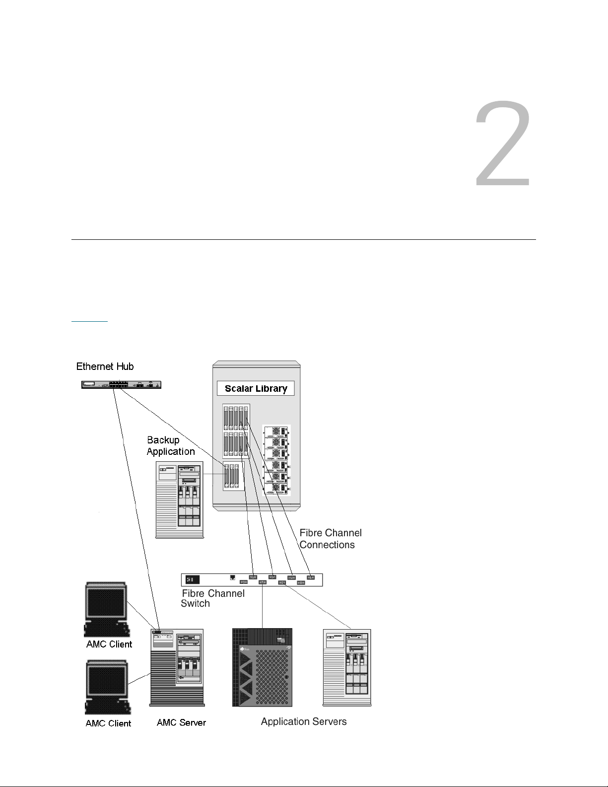
Description
This chapter describes AMC (the ADIC Management Console). AMC is a fully-featured management tool
for storage-area networks (SANs) with storage networking controller (SNC) or management control blade
(MCB) connectivity. A SAN is a network linking servers or workstations to disk arrays, tape backup systems,
switches, bridges, and other devices, over high-speed transports such as Fibre Channel or gigabit Ethernet.
SANs keep storage traffic away from network traffic without compromising rapid access to stored data. See
Figure 1
Figure 1 Example of typical storage-area network (SAN)
.
ADIC Management Console User’s Guide 3
Page 12

AMC provides several levels of access permissions and the ability to customize views and portals. By
keeping track of different client views, you can recall a saved view from any client. The server provides
security features by maintaining account names and passwords on behalf of the client application. AMC also
provides functionality to support server-less backup, tools for LUN mapping, and easy channel zoning.
ADIC Management Console Functionality
AMC uses a three-tier client/server model. The three parts are: agent, server, and client. The agent
communicates with the server and other managed agents via both Simple Network Management Protocol
(SNMP) and SCSI over IP (SOIP) protocols. The server communicates with the agent as well as with the
client or clients.
The Java Remote Method Invocation (RMI) API is used to communicate from the client to the server. You
can install one or more instances of the server onto systems in the SAN running any of the UNIX or Windows
platform software that are remote from MCBs or SNCs. Do not install more than one server per client
system.
Using the SAN Client
The SAN client for the Scalar series of libraries is the AMC. Using AMC is an easy way to manage Scalar
libraries as part of a SAN solution. When you choose to install both server and client from the product CD—
this is called the Full installation—the default client is the AMC SAN client. The default AMC client consists
of a Java-based user interface window and a trap event window. You can install one or more instances of
the AMC client in your SAN.
Using a Library Management Client
If your SAN includes a library in the intelligent platform (i-platform) series—for example a Scalar i2000 or a
Pathlight VX—you can launch a library management client from the AMC SAN interface. The library
management client launched in this way is identical to the interface that runs on the library’s touch screen.
ADIC Management Console Features
AMC provides status and controls for library and SNC features. The following features define the
management capabilities of AMC:
Event Logging
You can retrieve and view event logs. Filtering based upon the significance of events simplifies fault
isolation. For more information, refer to Monitoring and Managing Event Logs
Policies on page 54.
Reports
You can print or save reports that you have configured to meet your reporting requirements. For more
information, refer to Reporting the Current View
on page 51.
on page 89 and Configuring
4 Description
Page 13

Heartbeat
AMC monitors system components to ensure continuity of service. If an SNC or MCB is no longer available,
the server component notifies monitoring clients.For more information, refer to Checking the Heartbeat
page 99.
on
Health Checks
Instantaneous and periodic health checks allow monitoring of each appliance and the devices attached to
it. For more information, refer to Using Health Check
on page 98.
Channel Zoning
Channel zoning is a means of managing the access security between SAN connections and SCSI or FC
devices on a channel by channel basis.
• Channel zoning can be used to secure access between a server and its storage, segregating them,
for example, from other servers and their respective storage.
• The default settings allow all SAN connections to access all SCSI or FC devices.
Data Mover
The SNC can move data directly between storage devices that are attached to it. Data Mover frees-up
valuable system resources on the server and substantially increases the speed of backup and restore
operations.
Data Mover is the engine for server-free backup and restore and hierarchical storage management
applications that support the extended copy specification (ANSI T10/99-143r1).
Scalar® Firewall Manager / Virtual Private SAN
Scalar® Firewall Manager (SFM) and Virtual Private SAN® (VPS) technology enable SANs with multiple
users to share the same connectivity channels in order to access the same or different storage elements by
creating multiple virtual private connections.
SFM and VPS manage the access between an initiator (user, host, system) and a target/logical unit number
(LUN).
extended VPS
The extended Virtual Private SAN® (eVPS) functionality enables access control and mapping of FC and
SCSI devices and provides the flexibility to map the attached devices to any user-defined LUN separately
and individually for each Fibre Channel attached host. Because eVPS is backwardly compatible, current
users of VPS and SFM can preserve current mappings when their licenses are upgraded.
®
®
Virtual Private Map
Virtual Private Map (VPM) technology enables legacy and new systems equipped with SCSI host bus
adapters to access Fibre Channel devices. VPM allows Fibre Channel and SCSI target devices to be
mapped to private SCSI host channels.
ADIC Management Console User’s Guide 5
Page 14

SNMP
SNMP (Simple Network Management Protocol) community strings are a part of the software agent’s
messaging functionality that serve to group network devices into logical collections for management
purposes. The community strings on the server must match those on the appliance(s) you wish to manage.
Three strings are defined:
• Read— for querying the appliance
•Write—for controlling the appliance
• Trap—for receiving event messages from the appliance
The appliance can maintain 32 read and 32 write community strings and one trap community string.
A set of commands is provided for manipulating the Read and Write SNMP community strings. These
strings logically group devices into management communities.
Library RMU Support
Data obtained from a Scalar library’s RMU (remote management unit) includes global status data, drive
data, and mover data. These data are displayed in the AMC data panel. RMU data can also be displayed
from a library’s right-click menu.
Security
Four levels of user privilege are defined, each with specific capabilities. For more information, see Table 1
on page 36.
Network Discovery
Network discovery allows you to locate any appliance based on network addresses and ranges. This allows
management of an appliance without knowing the specific Internet Protocol (IP) address beforehand.
Configuration Options
You can set up an appliance with a number of non-default parameters, channel settings, and event
management variables. For more information, refer to Performing Administrative Tasks
Configuring SAN Access
on page 71.
on page 53, and
Updating Firmware
You can update appliance and device firmware from the client. For more information, refer to Updating
Firmware on page 60.
Obtaining Drive Dumps
You can download and save the drive's transaction and error logs. Sometimes this information is requested
by service personnel for analysis. For more information, refer to Obtaining a Drive Dump
on page 99.
Command Flow Logging
Logs of the SCSI commands processed by the SNC can be retrieved for analysis by service personnel. For
more information, refer to Checking the Command Flow Log
6 Description
on page 100.
Page 15

Getting Started
Note
The AMC server communicates over Ethernet to its clients. To manage a SAN, install an instance of the
server onto any open-platform system that is connected via Ethernet to each SNC and each AMC client.
You must install at least one instance of the server to manage your SAN with AMC. The AMC client can be
launched from any connected system on which it is installed. For intelligent-platform libraries, a library
management client can also be launched from the AMC SAN client.
A client capable of managing the SAN cannot be launched from the library
management client on an i-platform library.
Installation Requirements
Minimum configuration guidelines for each system are presented below for the AMC 4.4 version of software.
Server System Requirements
Java Runtime Environment 1.4.1 is installed with AMC. The version of the operating system you choose
must support this level.
Windows
The installation requirements for Microsoft® Windows® 2000, Microsoft® Windows® XP, or Microsoft®
Windows® 2003 are as follows:
• Windows 2000, Microsoft Windows XP, or Microsoft Windows 2003
• Minimum memory: 96MB
• Free hard disk space: 40MB
• Ethernet with TCP/IP protocol installed
AIX
The minimum installation requirements for AIX are as follows:
• AIX® 5.3
• 128 MB system memory
• 60 MB of free disk space on destination partition
ADIC Management Console User’s Guide 7
Page 16

HP-UX
Note
The installation requirements for HP-UX are as follows.
•HP-UX
• 80MB or greater system memory
• 80MB free disk space in the destination partition
TM
11.0 or later
Solaris
The installation requirements for Solaris are as follows.
•Solaris
• 80MB or greater system memory
• 60MB free disk space in the destination partition
• Common Desktop Environment (CDE)
TM
9 (5.9). The maintenance level must support JDK 1.4.1
Limitations in the OpenWindows Desktop Environment inhibit drag and drop
editing functions in AMC’s Device Mapping and VPM dialog boxes. If you
need to use either of these AMC features, you must use the CDE rather than
the OpenWindows Desktop Environment.
Linux
The installation requirements for Red Hat Linux are as follows.
• Advanced Server 2.1 or Enterprise Server 3.0
• Minimum memory: 80 MB
• Free hard disk space: 60 MB
• Ethernet with TCP/IP protocol installed
• Video adapter board for graphical input
Client System Requirements
Windows
• Windows 2000, Microsoft Windows XP, or Microsoft Windows 2003
• Minimum memory: 96 MB
• Free hard disk space: 30 MB
• Ethernet with TCP/IP protocol installed
UNIX platforms
Follow the requirements for the appropriate server platform, above.
8 Getting Started
Page 17

Before Installing AMC
CAUTION
CAUTION
AMC uses Ethernet to communicate. Your Ethernet network must be in place before AMC is installed.
Verify that you have enough space, about 100 MB, in the temporary
directory to be able to complete the installation.
1 Obtain the network parameters for the client, the server, as well as any other Scalar libraries in the SAN.
• Use static IP addresses.
• If the Scalar libraries in the SAN are not on the same TCP/IP subnet as the server, assign a
default network gateway address and/or route table entries.
2 Save this configuration information for future reference.
3 Run Ethernet cable from the server to the network hub or switch.
4 Run Ethernet cable from clients to the network hub.
5 Run Ethernet cable from the network hub to the Scalar libraries in the SAN.
6 Configure the network according to the procedures for the operating system you are using.
Installing the AMC Server
To manage your SAN, you must install an instance of the server onto a system that is connected by Ethernet
to your storage products and the systems where the clients are running. This server cannot be identical to
the server embedded in the i-platform libraries.
Installing the Server on a Windows System
Install the AMC server after you have completed the steps in Before Installing AMC on page 9.
1 Load the product CD.
2 Click the install link under the ADIC Management Console.
3 Click OK.
This starts the InstallAnywhere program, which prompts you throughout the installation.
4 When you are prompted to choose an installation set, select Server Only if you do not wish to run the
AMC client on that host, or Full if you do.
AMC server version must match AMC client version. When the client
and the server are different versions, they may not be able to
communicate.
5 When you are asked to configure network discovery, be sure the network segment you define includes
the SAN components you identified in Step 2
of Before Installing AMC on page 9.
6 The e-mail configuration portion of the installation requires the following information:
• Network name of your mail server, for example, MyMailServer.
• Valid e-mail account for the specified SMTP server, for example, Joan.Dow
• Valid password for this e-mail account, for example, *u!nBe
ADIC Management Console User’s Guide 9
Page 18

• E-mail address that you want mail recipients to see when AMC contacts them. This need not be an
CAUTION
CAUTION
e-mail address that has been previously validated by a working mail server, for example,
AMCAlert@MyCompany.com
7 Proceed to Launching the AMC Server
on page 11.
Installing the Server on a UNIX System
Install the AMC server after you have completed the steps in Before Installing AMC on page 9.
1 Load the product CD.
2 Navigate to the ADIC Management Console folder.
3 Open the folder and copy the image file to a temporary folder on the host.
Verify that you have enough space, about 100 MB, in the temporary
directory to be able to complete the installation. On Solaris systems,
if the /tmp directory is not large enough for InstallAnywhere to
operate, the installation fails, even if the temporary directory is
resized later.
Set the IATEMPDIR environment variable to the name of a directory
that is big enough. InstallAnywhere uses that directory instead of
/tmp.
To set the variable for Bourne shell (sh), ksh, bash and zsh:
$IATEMPDIR=/your/free/space/directory $ export
IATEMPDIR -
To set the variable for C shell (csh) and tcsh:
$ setenv IATEMPDIR /your/free/space/directory
4 From the temporary folder, type: chmod 777 <filename>, for example,
chmod 777 MC043SOL.bin
and press Enter.
5 If the temporary folder is NOT in the user's path, type [space]./<filename>, for example,
./MC043HPX.bin
and press Enter.
This launches the installation from the current directory.
If the temporary folder is in the user's path, simply type: <filename> (including extension),
for example,
MC043LIN.bin
and press Enter.
This starts the InstallAnywhere program, which prompts you throughout the installation.
6 When you are prompted to choose an installation set, select Server Only if you do not wish to run the
AMC client on that host, or Full if you do.
AMC server version must match AMC client version. When the client
and the server are different versions, they may not be able to
communicate.
10 Getting Started
Page 19

7 When you are asked to configure network discovery, be sure the network segment you define includes
Note
Note
the SAN components you identified in Step 2
8 The e-mail configuration portion of the installation requires the following information:
• Network name of your mail server, for example, MyMailServer.
• Valid e-mail account for the specified SMTP server, for example, Joan.Dow
• Valid password for this e-mail account, for example, *u!nBe
• E-mail address that you want mail recipients to see when AMC contacts them. This need not
be an e-mail address that has been previously validated by a working mail server, for example,
AMCAlert@MyCompany.com
of Before Installing AMC on page 9.
9 Proceed to Launching the AMC Server
.
Launching the AMC Server
After you launch the server, be sure it completes network discovery before you launch the client. When a
server has completed network discovery and is ready to receive connections, the message Ready.
Waiting for commands is displayed above the prompt in the server window.
Launching a Windows Server
Launch the server at the beginning of your SAN Management session, but do not exit the server when you
are finished. Leave the server running.
1 Select the Start button, point to Programs.
2 Point to ADIC Management Console. Then select Server.
If you installed the AMC server on a non-default path, launch it from that location instead.
Once you launch the server, a window opens on your monitor. You will know that network discovery has
been completed when you see the message Ready. Waiting for commands followed by a
command prompt.
If your configuration consists of many large or remote network segments, discovery can take several
minutes to complete.
Do not close the server window. Follow the exit procedure in Shutting Down the
AMC Server on page 17 to shut the server down.
3 Proceed to Launching the AMC Client
on page 13.
Launching a UNIX Server
Launch the server at the beginning of your SAN Management session, but do not exit the server when you
are finished. Leave the server running.
• To launch the AMC server from a UNIX system, type Server from a terminal window, and press
Enter.
Server <enter>
Uppercase S is mandatory.
ADIC Management Console User’s Guide 11
Page 20

The server window is displayed.
Note
If your configuration consists of many large or remote network segments, discovery can take several
minutes to complete.
Do not close the server window. Follow the exit procedure in Shutting Down the
AMC Server on page 17 to shut the server down.
Proceed to Launching the AMC Client
on page 13.
Installing the AMC Client
The AMC Client is used to manage your SAN.
Before Installing the Client
If you have already installed an instance of the client, and want to install another, or if you have already
installed an instance of the AMC server using the Server Only installation option, proceed to either Installing
a Windows AMC Client or to Installing a UNIX Client.
If you have already installed an instance of AMC using the Full option, and do not want to install another
client, proceed to Launching the AMC Client
Otherwise, complete the sections Before Installing AMC
9 before proceeding with the client installation.
Installing a Windows AMC Client
An AMC Windows client can run on Windows 2000 or Windows XP.
1 Load the product CD.
on page 13.
on page 9 and Installing the AMC Server on page
2 Click the install link under the ADIC Management Console.
3 Click OK.
This starts the InstallAnywhere program, which prompts you throughout the installation.
4 When you are prompted to choose an installation set, select Client Only.
5 Proceed to Launching the AMC Client
on page 13.
Installing a UNIX Client
An AMC client can run over Solaris, Linux, HP-UX, or AIX.
1 Load the product CD.
2 Navigate to the ADIC Management Console folder.
3 Open the folder and copy the image file to a temporary folder on the host.
12 Getting Started
Page 21

CAUTION
Verify that you have enough space, about 80 MB, in the temporary
Note
directory to be able to complete the installation. On Solaris systems,
if the /tmp directory is not big enough for InstallAnywhere to operate,
the installation fails, even if the temporary directory is resized later.
Set the IATEMPDIR environment variable to have the name of a
directory which is big enough. Then InstallAnywhere will use that
directory instead of /tmp.
To set the variable for Bourne shell (sh), ksh, bash and zsh:
$IATEMPDIR=/your/free/space/directory $ export
IATEMPDIR -
To set the variable for C shell (csh) and tcsh:
$ setenv IATEMPDIR /your/free/space/directory
4 From the temporary folder, type: chmod 777 <filename>, e.g.
chmod 777 MC043SOL.bin
5 If the temporary folder is NOT in the user's path, type [space]./<filename>, e.g.
./MC043SOL.bin
This launches the installation from the current directory.
If the temporary folder is in the user's path, simply type: <filename> (including extension),
e.g.
MC043SOL.bin
This starts the InstallAnywhere program, which prompts you throughout the installation.
6 When you are prompted to choose an installation set, select Client Only.
7 Proceed to Launching the AMC Client
.
Launching the AMC Client
To manage your SAN, connect your client to an instance of the AMC server that is remote to the Scalar
i2000, Scalar i500, or Pathlight VX.
When a remote server is ready to receive connections, the message Ready.
Waiting for commands is displayed above the prompt in the server
window.
Use one of the following procedures to start the client, depending on the operating system your client is
running:
Launching a Windows Client
If you launch the client before the remote server has completed discovery, the client will not attach to the
server.
1 If you accepted the defaults during the installation, select the ADIC Management Console program
group on the Start menu to see the client icon. If you chose a program group other than the default, go
there instead.
ADIC Management Console User’s Guide 13
Page 22

2 Select Client to launch the program.
CAUTION
Note
Note
Note
When the client launches, both the ADIC Management Console window and a Receive Event Traps
window appear. If event traps are issued, messages appear in the Received Event Traps window. You
cannot close the Received Event Traps while the client is running but you can minimize it.
3 If the remote server is running on a system that is also remote to the client, the client window displays
a prompt for you to connect to a server. Proceed to Connecting to the Server
If the remote server is running on the same system as the client, connection to the server is automatic.
The client window displays a logon prompt. Proceed to Logging on
After the initial log in, set up another SAN administrator. Setting up a
SAN administrator will disable the default admin logon name. Refer to
Adding a New User Account on page 37
on page 15.
.
.
Launching a UNIX Client
If you launch the client before the remote server has completed discovery, the client will not attach to the
server.
1 To start the HP-UX, AIX, Solaris, or Linux client, start a terminal window and type
Client <enter>
and press Enter.
Uppercase C is mandatory.
When the client launches, both the ADIC Management Console window and a Received Event Traps
window appear. If and when event traps are issued, messages appear in the Received Event Traps
window. You cannot close the Received Event Traps while the client is running. You can minimize it.
2 If the server is running on a system that is remote to the client, the client window prompts you to connect
to a server. Proceed to Connecting to the Server
If the server is running on a system that is local to the client, connection to the server is automatic. The
client window displays a logon prompt. Proceed to Logging on
.
on page 15.
Connecting to the Server
If the client is local to the server, connection is automatic.
1 In the Connect to Server dialog box, type the network name or IP address of the remote server.
If you type the IP address of an i-platform library, you will not be able to
manage your SAN. The servers installed on i-platform libraries are used to
manage library operations.
2 Select OK.
If your client is already launched, you can display the dialog box by selecting
the Session menu, and then selecting Connect to Server.
3 Proceed to Logging on
14 Getting Started
on page 15.
Page 23

Logging on
CAUTION
The Log On dialog box is displayed automatically when a new connection to the server has been
established. It can also be displayed when you select Session and then select Log On. The Logon dialog
box is also displayed when you select the Log On toolbar button.
In the Logon dialog box, type "admin" as the user name. Type "password" as password, if this is the first
time you have logged on.
After the initial log in, set up another SAN administrator. Setting up a
SAN administrator will disable the default admin logon name. Refer to
Adding a New User Account on page 37
If you make an error logging on, the logon dialog box disappears and Unsuccessful log on appears in the
Status/Message Area of the screen. Refer to Status/Message Area
and re-type your logon information.
If your log on is successful, the client displays a status bar as it downloads master portal data. For more
about the master portal and portals in general, refer to Working with Portals
.
on page 33. Select Session > Log On,
on page 39.
ADIC Management Console User’s Guide 15
Page 24
The default master portal consists of all the devices discovered, according to the discovery configuration
file. When the download is complete, the AMC screen is filled with data. For information about this screen,
refer to Reading the SAN Management Information Panels
on page 24.
Logging off
Log off after you finish using AMC. You will not need to restart the client before your next management
session.
1 Select the Session menu, then select Log Off.
A warning dialog box is displayed.
You can also launch the Log Off dialog box by selecting the Log Off toolbar button.
The warning dialog box is displayed.
2 Select Yes if you want to log off. If you select Yes, you are prompted to save your current view, if it has
changed.
The Save Current View dialog box is displayed.
16 Getting Started
Page 25

Select No if you have changed your mind. If you select No, you are returned to your view.
Note
3 Select Yes if you have made changes to the view that you want to save.
Select No if you do not want to save changes.
Exiting the AMC Client
Exit stops the AMC client application and closes its window.
Use Exit if you want to restart the client application the next time you use AMC. Normally you will only log
off, and leave the client running between sessions.
1 After logging off, select Session > Exit.
The Exit dialog box is displayed.
2 Select Yes if you want to exit. Your view is closed.
Select No if you have changed your mind.
If you select No, you are returned to your closed view.
Shutting Down the AMC Server
The way that the AMC server is shut down is the same for all platforms.
You cannot shut down the server that is embedded in an i-platform library.
1 After you have logged off (refer to Logging off
AMC Client), position the cursor after the command prompt in the server window.
2 Type "exit", then press the Enter key.
The server window disappears.
on page 16), and exited the client (refer to Exiting the
ADIC Management Console User’s Guide 17
Page 26

18 Getting Started
Page 27

Frequently Asked Questions
This section provides a reference of commonly asked questions and their answers.
What is a SAN?
A storage area network (SAN) links servers or workstations to disk arrays, tape backup systems, switches,
bridges, and other devices, over high-speed transports such as Fibre Channel or gigabyte Ethernet.
What if I cannot see any SAN components after I install?
If you did not change the sample network segment statement (1.1.1.1 - 1.1.1.2) that appears in the
Configure Discovery Settings screen of the installation wizard, SAN components will not be discovered.
Follow the instructions in Discovering the SAN
statements that reflect your network environment. Add a separate statement for every subnet. Instructions
are also given in this section for re-discovering the SAN.
on page 55 to modify the sample statement and to add
What is the i-platform series?
The intelligent platform (i-platform) libraries all have integrated management services within intelligent
storage devices designed specifically for operation in a storage network.
Can I manage a SAN from an i-platform library?
No. For libraries in the i-platform—such as the Scalar i2000, Scalar i500, and Pathlight VX—AMC is
available only from a remote client.
Do I have to install a server or client?
To manage the SAN you must install at least one instance of the AMC server and client on at least one
remote system. Refer to Before Installing AMC
per client computer. You should upgrade both server and client when or if you upgrade, so that the server
and the client communicate most effectively.
on page 9. Do not install more than one instance of a server
To manage a Scalar i2000 remotely (that is, not from the touch panel) you must install a SAN client.
ADIC Management Console User’s Guide 19
Page 28

Can I configure e-mail even if I skip that step during installation?
Refer to Configuring E-mail on page 53.
How do I interpret interface components?
Refer to Reading the SAN Management Information Panels on page 24.
How do I create a SAN administrator account?
Refer to Adding a New User Account on page 37.
What is a portal?
A portal is a collection of storage area networking devices that represent a particular user’s universe. The
SAN administrator’s default portal is the entire set of SAN-capable appliances and associated storage on
the subnet to which the AMC has access. This is called the master portal. Other users are granted privileges
to subsets of the master portal by the SAN administrator.
How do I create user accounts?
Refer to Creating, Modifying and Deleting User Accounts on page 37.
How do I create portals for my users?
Refer to Creating a New Portal on page 39.
What privileges does each user type have?
See Table 1 on page 36.
How do I update firmware?
For the SNC and the devices connected to it, refer to Updating Firmware on page 60. For i-platform libraries,
use the appropriate library management client.
How do I modify the discovery configuration?
Refer to Discovering the SAN on page 55.
20 Frequently Asked Questions
Page 29

How do I create policies?
For the SAN, refer to Configuring Policies on page 54. For i-platform libraries, use the appropriate library
management client.
ADIC Management Console User’s Guide 21
Page 30

22 Frequently Asked Questions
Page 31

The SAN Management Interface
The AMC interface presents you with a number of menus and toolbar buttons.
Menus
AMC organizes user commands into a number of different menus:
•The Session menu consists of commands governing your current established connection:
connecting to the server, logging off and on, changing your password, and exiting the program.
•The View menu consists of commands affecting the logical graphical representations of a portal:
opening, saving, deleting, and creating views, as well as searching a view for a particular
component, finding out which other users have access to the view, or printing view-based reports.
•The Admin menu consists of commands affecting SAN configuration, such as creating and
managing users, portals, community strings, and policies.
•The Category menu consists of commands affecting categories—SAN components organized into
logical groups.
•The Help menu provides access to online help, a statement of the server and client build numbers,
and a copyright statement.
Toolbar
The toolbar consists of six buttons, representing commonly used commands that are also available on the
menus.
• Log On launches the Log On dialog box. If there is a current user, confirmation must first be
received that the current view will be closed.
• Log Off logs off the current user, after confirming the log off request.
• Open View launches a view browser, after confirming that the current view should be closed.
• Save Current View immediately saves the current view. This button is unavailable unless changes
have been made to the view.
• Close Current View closes the current view after confirming the close view request. If changes
have been made to the view, the user is prompted to save them first.
• Find displays a dialog box used to search for a specific SAN component.
ADIC Management Console User’s Guide 23
Page 32

Panels
Note
The AMC interface consists of three information panels:
• The navigation panel presents you with a hierarchically organized representation of SAN
components, using special graphical conventions as well as textual information to represent SAN
structure.
• The graphical panel presents you with a graphical representation of your SAN, with hyperlinked
icons that control information in the data panel.
• The data panel lists component, configuration, and build specifications for SAN components.
Received Event Trap Window
Whenever AMC is running, a separate window showing the received event traps is always open. This
window can be minimized, but not closed.
When the AMC SAN client is launched, a Received Event Traps window is displayed at the same time as
the SAN Management window. If and when event traps are issued, messages appear in this window. You
cannot close this window while the client is running, but you can minimize it. For more about traps, refer to
Monitoring and Managing Event Logs
on page 89.
Reading the SAN Management Information Panels
The AMC main screen is made up of three panels.
• The navigation panel lists SNCs and libraries with SNCs in IP address order. Detailed information
about each configuration is coded into the display, both verbally and graphically.
• When an SNC or library has been selected in the navigation view, the graphical panel represents
configuration information for that unit in a nonverbal format.
• When an SNC or library has been selected in the navigation view, the data panel presents status
information about it in table format.
Navigation Panel
The left panel of the interactive display is called the navigation panel. In it, SAN components are
hierarchically displayed.
SNCs and Scalar 24, 100, 1000, and 10K Libraries
The navigation panel string representing a standalone SNC, a Scalar 24, a Scalar 100, a Scalar 1000, or a
Scalar 10K consists of three elements: the unit’s IP address, its name, and its product family.
Click the node symbol at the left of a library’s graphic to show aggregated Storage Networking Controllers
(SNCs).
An SNC is considered aggregated when it has been installed in a library, as
opposed to performing as a standalone unit.
The node symbol is a toggle. Clicking it a second time collapses the expansion.
• Scalar 10K tape libraries contain multiple SNCs
24 The SAN Management Interface
Page 33

• Scalar 1000 tape libraries contain three SNCs
• Scalar 100 tape libraries contain one SNC
• Scalar 24 tape libraries contain one SNC
SNC nodes expand to show channels. Channels expand to show attached hosts and devices. The node
symbol for SNCs and channels also functions as a toggle. Clicking it a second time collapses the expansion.
See Figure 2
.
Figure 2 AMC representation of SNCs and system components
ADIC Management Console User’s Guide 25
Page 34

Figure 2 on page 25 shows a navigation panel with several navigation elements expanded. Because the
SNC 5100 with IP address 172.16.76.215 is selected, it is shown in the navigation panel with blue
highlighting. This SNC is aggregated into a Scalar 1000. For a list of symbols used in the graphical and
navigation panels, see Figure 3
.
Figure 3 Symbols used in graphical and navigation panels
For a summary of channel mode graphics, see Figure 4
Figure 4 Channel mode graphics
.
26 The SAN Management Interface
Page 35

Target is the default mode for Fibre Channels. They are shown in blue. When channels are set to Target,
you are able to see attached hosts. You must first be running the host registration software (HRS). Talk to
your service representative about installing this software.
Green indicates that the channel is in Initiator mode. Initiator is the default mode for SCSI channels.When
channels are set to Initiator you are able to see attached devices.
In addition to Target mode and Initiator mode, Fibre Channels can function in Target and Initiator mode.
When that is the case, the Fibre Channel icon is purple.
AMC displays both SCSI hosts and Fibre Channel hosts that are running HRS. Refer to the User’s Guide
for your SNC for information about installing HRS.
Right-clicking a selected Fibre Channel, a SCSI channel, a device, or the SNC in the navigation panel
displays a command menu appropriate to the element you have right-clicked. To see these menus, refer to
the following sections:
• Getting Information About a Library
• Managing the SAN Appliance
• Managing the Fibre Channel
• Managing the SCSI Channel
• Managing a Device
Refreshing data in the navigation panel causes the graphical and data panels to refresh as well.
on page 68
on page 61
on page 57
on page 65
on page 63
Scalar i2000 and Scalar i500
The navigation panel string representing the Scalar i2000 or Scalar i500 physical library consists of three
elements: the IP address, the library’s name (for example, adiclib), and the library product identity (for
example, Scalar i2000). Click the node symbol to the left of the library to show associated devices (drives)
and partitions. All nodes have been expanded in Figure 5
it a second time collapses the expansion.
on page 28. The node symbol is a toggle. Clicking
ADIC Management Console User’s Guide 27
Page 36

Figure 5 AMC representation of the Scalar i2000
The Scalar i2000 library In Figure 5
consists of a physical library divided into two partitions. In the line below
the physical library line, the string representing the partition consists of two elements: the word Partition
followed by the name of the partition. The partitions in Figure 5
are named SDLT and LTO. The tape device
strings consists of the phrase SCSI Tape Device, followed by the location coordinates for the drive. Fibre
Channel Tape Device is also possible in this area. For an explanation of these features, refer to the Scalar
i2000 User’s Guide or to the Scalar i500 User’s Guide.
28 The SAN Management Interface
Page 37

Pathlight VX
The navigation panel string representing the Pathlight VX is analogous to the string for the Scalar i2000 and
Scalar i500. Figure 6
nyvp1_lib1. This virtual library consists of three drives. For more information about virtual libraries and
drives, refer to the Pathlight VX online help.
Figure 6 AMC representation of the Pathlight VX
shows the Pathlight VX as an expanded node. It consists of one virtual library named
ADIC Management Console User’s Guide 29
Page 38

Device Numbering
Figure 2 on page 25 displays devices on different channels. The devices are all numbered according to a
standard scheme. To interpret the numbering, see Figure 7
• The number before the colon inside the square brackets represents the target ID (or SCSI ID).
• The number after the colon inside the square brackets represents the device LUN (Logical Unit
Number). This number is also sometimes referred to as the target LUN.
• The number after the dash is the assigned LUN. This number is also sometimes referred to as the
internal LUN.
Figure 7 Device numbering conventions
SCSI channels provide target space for IDs 0-15. Device LUNs 0-31 are associated with each ID. The
assigned LUN is the LUN the appliance assigns during discovery. The target ID and device LUN are
physical concepts.
.
The Assigned LUN is a management concept and may be manipulated by the user to create private device
maps. Refer to Editing Device Maps
eVPS on page 80, or Using VPM on page 86.
on page 69, Using Scalar Firewall Manager (SFM) on page 76, Using
Graphical Panel
On the right side of the screen, above the data panel, is a graphical representation of the networked
configuration for the selected SNC. This is the graphical panel.
For standalone SNCs or for Scalar libraries that contain a storage networking appliance, selecting the SNC,
a channel, a host, or a device in the navigation panel highlights in blue the associated symbol in the
graphical panel. Unselected SCSI channels are drawn in black. See Figure 2
Channels are drawn in yellow.
Selecting an i-platform library also causes a display in the graphical panel. For example, a labeled black
rectangle represents the physical library, inside of which an appropriate number of blue bars represents the
associated number of partitions. A labeled black rectangle is also used to represent the Pathlight VX
physical library, inside of which an appropriate number of blue bars represents the associated number of
virtual libraries. See Figure 5
Right-clicking a selected Fibre Channel, a SCSI channel, a device, or the SNC in the graphical panel
displays a command menu appropriate to the element you have right-clicked. To see these menus, refer to
the following sections:
• Getting Information About a Library
on page 28 and Figure 6 on page 29.
on page 61
on page 25. Unselected Fibre
• Managing the SAN Appliance
• Managing the Fibre Channel
• Managing the SCSI Channel
• Managing a Device
30 The SAN Management Interface
on page 68
on page 57
on page 65
on page 63
Page 39

Data Panel
On the right side of the screen, below the graphical panel, is a tabular representation of selected status
information. This is the data panel.
When a library is selected in the navigation panel, the following pieces of information, reported by the
library’s remote management unit (RMU), are displayed in the data panel:
Global Status Current summary status of the library: unknown, ok,
degraded, or failure
Last Global Status Last summary status of the library: unknown, ok,
degraded, or failure
SNMP Timeout Refer to the documentation for the appropriate library
Agent Modifiers Refer to the documentation for the appropriate library
Refresh rate Refer to the documentation for the appropriate library
IP Address A unique Internet Protocol Address
Host Name Domain Name Server (DNS) host name of the RMU
RMU Version Current firmware level of the library
Shutdown State Current shutdown status of the library: other, unknown,
normal, powerfail, errorreboot
Last Shutdown State Last shutdown status of the library: other, unknown,
normal, powerfail, errorreboot
Error Code Integer value supplied for some Service Action Codes
Error Data Parameter that adds precision to the Service Action
Code
Service Action Code Code used in diagnostics
Service Tag Identification number of the original configuration
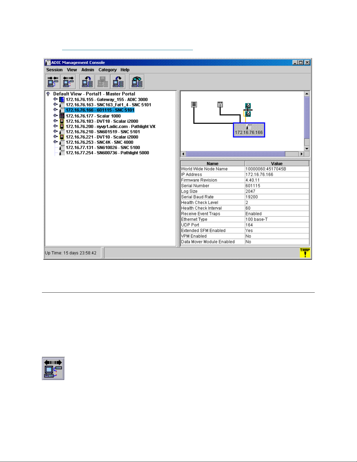
When an SNC is selected, the lower part of the data panel displays the following information:
World Wide Name A globally unique node_name
IP Address A unique Internet Protocol Address
Firmware Revision A number in xx.xx.xx format indicating the level of
firmware on the SNC
Serial Number Number assigned to the SNC during manufacturing
Log Size Size of the log file on the SNC
Serial Baud Rate Speed of the HyperTerminal connection
Health Check Level Level to which Health Check is set, 0-4
Health Check Interval Interval between Health Checks, in minutes
Receive Event Traps Status--either Enabled or Disabled
Ethernet Type 10-base T or 100-base T
ADIC Management Console User’s Guide 31
Page 40

UDP Port User Datagram Protocol port where SNMP traps are
received
VPS Enabled
Yes (enabled) or No (disabled)
SFM Enabled
VPM Enabled Yes (enabled) or No (disabled)
Data Mover Module Enabled Yes (enabled) or No (disabled)
When a SCSI channel is selected, the lower part of the data panel display presents the following
information:
Channel Type Low Voltage or High Voltage, Single-Ended or
Differential
Channel Mode Target or Initiator
Host ID (if channel in initiator mode) SCSI Bus Channel ID
Termination Status--either Enabled or Disabled
Max Width Bus width, in bits
Max Speed
Bus speed in megahertz
Status Status--either Operational or Offline
Max IDs per Bus (if channel in initiator mode) Number of SCSI IDs allowed
Max LUNs per ID (if channel in initiator mode) Number of SCSI LUNs allowed
When a Fibre Channel is selected, the lower part of the data panel display presents the following
information:
World Wide Port Name Unique 64-bit identifier assigned to this port
World Wide Node Name Unique 64-bit identifier assigned by the manufacturer
Serial Number Number assigned to the FC connector during
manufacturing
Media Short Wave or Long Wave, Dual or Single PMC or
GBIC type
Firmware Revision FC controller firmware version
Port Type Point-to-Point (N_Port), fabric loop (NL_Port),
Fabric_Attached (N_Port), or none
Port Mode Public or Private, Initiator or Target
Address Identifier Arbitrated Loop_Physical Address (AL_PA) Address
Host Type OS of attached Host
Loop ID 0-125
Frame Size 512, 1024, or 2048
Frame Buffer Size Storage space, usually bigger than a single frame
32 The SAN Management Interface
Page 41

Connection Connection options for FC chips
Max Speed 1 GB or 2 GB
Status Ready or Not Ready
Link Error Statistics Header: Subsequent numbers are errors counted by
SNC on full duplex channel between two network fabric
connections
Link Failure Count Counts used in diagnostics
Loss of Sync Count Counts used in diagnostics
Loss of Signal Count Counts used in diagnostics
Primitive Sequence Protocol Error
Count
Invalid Transmission Word Count Transmission word is 40 bits, smallest information unit
Invalid CRC Count Cyclic Redundancy Check, an error detection algorithm
When a device is selected, the lower part of the data panel display presents the following information:
Vendor ID Vendor Name
Product ID Product Name, assigned by Vendor
Revision Vendor’s release number
Serial Number Number assigned to the device during manufacturing
Removable Yes or No
Capacity For Disk devices, Number of Blocks
Block Size For Disk devices, Size of block
Transmission word containing special control
information. A primitive sequence is recognized when
three transmission words of the same value are
received
transmitted
Width For Tape devices, Bus width in bits
Speed For Tape devices, Bus speed
Status/Message Area
The area at the very bottom of the screen is used to display status messages. It is called the
Status/Message Area.
In the leftmost corner of the Status/Message Area, the up time for the selected SNC is displayed. Up Time
indicates how many hours, minutes and seconds have elapsed since the SNC was last booted.
ADIC Management Console User’s Guide 33
Page 42

Common SAN Management Options
When you select a view in the navigation panel, no topological representation is drawn. Right-click the view
in the navigation panel for some of the most common SAN management operations. See Figure 8
Figure 8 Commands at navigation panel root view
.
The data panel displays no data. For more on the graphical panel and the data panel, refer to Reading the
SAN Management Information Panels on page 24.
Auto-Categorize
Refer to Auto-Categorizing the SAN on page 43.
Creating a new Category
Refer to Working With Category Components on page 45.
Move Items
Refer to Moving Items by Using the Menu on page 47.
Find
Refer to Working With Views on page 47.
34 The SAN Management Interface
Page 43

Managing User Accounts
CAUTION
Note
AMC will enable you to create user accounts with the correct privilege levels for each user.
Changing the Administrator Password
SAN administrators must use this procedure to modify the SAN administrator password. To change a user’s
password, refer to Modifying a User Account
Be certain to change the SAN administrator password periodically.
The default admin/password account is disabled after a new SAN
Administrator account is created.
1 Log in as the SAN administrator.
2 Select the Session menu, then select Change Password.
The Change Password dialog box is displayed.
3 Type the old password in the first line.
4 Make a note of the new password.
5 Type the new password in the second line.
on page 38.
6 Confirm the new password by typing it again in the third line.
7 Select OK if you are satisfied with the new password.
Select Cancel to close the dialog box without making any changes.
After using admin/password the first time you log on, create a new user at the
SAN administrator level. Refer to Creating, Modifying and Deleting User
Accounts on page 37.
Understanding User Privilege Levels
All AMC tasks are assigned to one or more of four specific user profiles:
• SAN administrator
• Portal administrator
ADIC Management Console User’s Guide 35
Page 44

• Power user
• Basic user
The basic user has the most limited set of user capabilities, including access and view only of assigned
portals.
Power users have the basic user capability, as well as the ability to categorize assigned portals, save
various views, and use all AMC tools—except Virtual Private Map (VPM)—to configure access. However,
they cannot create, modify, or delete users, portals, or policies.
Portal administrators can carry out all basic user and power user tasks, as well as use all AMC configuration
tools. They can also create, modify, or delete power users and basic users, and subportals of portals to
which they have access. They cannot create policies. They cannot create users at the portal administrator
or SAN administrator level. They cannot access the Master Portal.
SAN administrators can perform all tasks assigned to other users. They also have the ability to create
policies and add users at the SAN administrator or portal administrator level. SAN administrators access
the Master portal by default. Table 1
summarizes user capabilities based on privilege levels.
Table 1 User Capabilities Based on Privilege Level
Capability SA
1
PA
2
PU
3
BU
4
Access the master portal Y N N N
Create, modify or delete any SA or PA Y N N N
Create, modify or delete a portal or subportal to which
YYNN
user has access
Create, modify or delete a PU or BU Y Y N N
Grant user access to portals Y Y N N
Create, modify or delete any view for portals to which
YYYN
user has access
Create views within portals to which the user has
YYYY
access
Delete view created by the user YYYY
Grant user access to views YYYN
Configure, re-initialize, view, and suspend policies Y N N N
Create new categories, rename a category, delete a
YYYN
category, move items or move categories
Configure channel zoning YYYN
Configure SFM/eVPS YYYN
Configure VPM Y Y N N
Enable Data Mover YYYN
Map devices Y Y
5
5
Y
N
Configure channels YYYN
1
SA=SAN administrator 2PA=portal administrator 3PU=power user 4BU=basic user 5If the portal defined for the
PA or PU includes only part of the appliance to be acted on, this privilege is assigned only to the SAN
administrator.
36 Managing User Accounts
Page 45

CAUTION
Note
Table 1 User Capabilities Based on Privilege Level (Continued)
Capability SA
1
Upload configuration Y Y
Upload firmware Y Y
Restart the appliance Y Y
Obtain CFL data Y Y Y
Obtain drive dumps Y Y Y
1
SA=SAN administrator 2PA=portal administrator 3PU=power user 4BU=basic user 5If the portal defined for the
PA or PU includes only part of the appliance to be acted on, this privilege is assigned only to the SAN
administrator.
PA
2
5
5
5
PU
Y
Y
Y
3
5
5
5
5
5
BU
N
N
N
N
N
4
Creating, Modifying and Deleting User Accounts
All users who are not SAN administrators must be assigned privileges for one or more portals. Create the
subportals before adding users. Refer to Working with Portals
Adding a New User Account
After the initial log in, set up another SAN administrator. Setting up a
SAN administrator disables the default admin logon name.
on page 39.
1 Log on as SAN administrator or portal administrator.
2 Select the Admin menu, point to User menu, then select New.
3 The New User Account dialog box is displayed. Type a name for the new user account.
User names are case-sensitive.
No two users can have the same user name.
4 Type the password after Enter Password and again after Confirm Password.
If you do not type the password the same way both times, a warning is displayed.
5 Assign a privilege level.
The choices are SAN administrator, portal administrator, power user, and basic user.
After you decide on the privilege level, use the radio buttons on the New User Account dialog box to
assign it.
6 Once the New User Account dialog box is completed, select Next.
The Grant Portal Access Permission dialog box is displayed.
Select the checkboxes to check them and clear them until access is appropriately assigned.
Select Back to assign the new user to a different privilege level.
Select Cancel if you decide not to add a new user.
ADIC Management Console User’s Guide 37
Page 46

7 When access is appropriately assigned, select Finish.
Note
For user privileges associated with the different commands, refer to Table 1 on
page 36.
Modifying a User Account
SAN administrators and portal administrators use this procedure to modify another user’s privileges. If you
are changing your own password, go to Changing the Administrator Password
1 Log on as SAN administrator or portal administrator.
2 Select the Admin menu, point to User, then select Modify.
3 Select the name of the user whose privileges you want to modify in the Modify User Account grid.
4 Select Next.
The Password dialog box of the Modify User Account process is displayed. The privilege level radio
button is defaulted automatically to the user’s current type.
5 If you are changing the password, type the new user password, and then type it again to confirm. If not,
proceed to Step 6
6 If you are changing the privilege level, select a radio button to assign a new privilege level to the user.
When you have finished with this dialog box, select Next.
.
on page 35.
7 Select the checkbox in front of an available portal or subportal to allow user access.
To remove access to a portal, clear the check box by selecting an existing check mark.
8 When access is correctly assigned, select Finish.
Select the checkboxes to check and clear them until access is appropriately assigned.
Select Back if you decide to modify a different user account.
Select Cancel if you decide not to modify any user privileges.
Deleting a User Account
1 Log on as SAN administrator or portal administrator.
2 Select the Admin menu, point to User, then select Delete.
3 Select the name of the user account you would like to delete.
4 Select Delete.
5 The Delete User Account dialog box is refreshed.
The user name you have just deleted does not appear in the list.
6 Select OK to delete the user account.
Select Cancel to stop the deletion process.
38 Managing User Accounts
Page 47

Working with Portals
This section contains procedures for administering portals. Portals are physical collections of libraries and
SAN appliances that are available to users, as defined by the SAN Administrator. The SAN Administrator
has access to the entire set of appliances and libraries described as the master portal.
Creating a New Portal
Create portals to assign access to devices, channels, views, and subportals.
The master portal initially consists of all SAN components recognized when the server performs its initial
discovery. Generally, SAN administrators retain access to the master portal and other users are granted
access privileges to subsets of the master portal.
Logical collections are created as categories and saved as views. Refer to Working with Categories and
Views on page 43.
1 Log on as SAN administrator or portal administrator.
2 Select the Admin menu, point to Portal, then select New.
3 Select the portal you want to subdivide, and select Next.
The New Portal dialog box shows a hierarchy of portals existing on the server. Initially, no subportals
of the default Master portal exist. After you have created some subportals, select whatever level of the
hierarchy is appropriate for the new subportal you are creating.
After a few moments, the New Portal dialog box refreshes to show all the attached appliances that
belong to the selected portal. The SNCs aggregated into libraries are displayed in this dialog box, but
the Scalar libraries themselves are not displayed. I-platform libraries are displayed.
When the user that has been assigned to this portal logs in, the Scalar libraries associated with SNCs
are displayed as a result of the network discovery process.
4 Expand the node in front of any IP address or channel to see associated devices.
To close the node, select it. Expanded nodes can exist in the same display as collapsed nodes.
5 Select the check boxes associated with items you want to include in the new portal.
Node check boxes are automatically filled in at the channel and appliance level when device check
boxes are selected. Devices selected for a new portal are shown here.
6 Select Next. The Portal Name dialog box is displayed.
7 Type a name for the new portal. The name must be unique.
ADIC Management Console User’s Guide 39
Page 48

8 When you are satisfied with the name, select Finish.
Note
New portals appear as subportals in the parent portal list.
Modifying a Portal
You cannot modify the master portal using this tool.
1 Log on as SAN administrator or portal administrator.
2 Select the Admin menu, point to Portal, then select Modify.
3 Select the portal that you want to modify.
4 Select Next.
5 Check or clear the boxes in front of SAN appliances to appropriately modify the portal definition.
In the example, access to all the SCSI channels on 172.16.76.167 and all the channels on the appliance
at 172.16.76.168 is indicated.
Devices attached to the Fibre Channels on 172.16.76.167 are not available.
6 When you are satisfied with the changes you have made, select Finish.
Portal successfully modified appears in the Status/Message Area.
40 Working with Portals
Page 49

Deleting a Portal
A portal can be deleted without loss to stored data. Deleting the only portal for a user will result in that user
having no access to the SAN.
1 Log on as SAN administrator or portal administrator.
2 Select the Admin menu, point to Portal, then select Delete.
3 Select the portal that you wish to delete. The Delete button becomes available.
4 Select Delete, and then select OK. The portal is deleted.
Setting Permissions for Portal Access
The SAN administrator can set permissions for all users. A portal administrator can set permissions for
power users and basic users within the portal(s) to which the portal administrator is assigned.
1 Log on as SAN administrator or portal administrator.
2 Select the Admin menu, point to Portal, then select Permissions.
3 Select the portal for which you are assigning or revoking access.
4 Select Next.
A list is displayed that consists of all users with access privileges to the portal you selected.
5 Select the check boxes in the Assign column to grant or revoke access to the selected portal.
6 Select Finish.
ADIC Management Console User’s Guide 41
Page 50

42 Working with Portals
Page 51

Working with Categories and Views
SAN components can be organized into logical groupings to facilitate SAN management. When you
categorize your SAN, you choose the categories—subnet, department, location, host type, etc. AMC uses
the file folder icon to represent a category. See Figure 3
navigation panel.
Working with SAN Categories
Creating categories of SAN appliances is an easy way to help you manage your SAN. Group appliances by
subnet, host characteristics, similarities in connectivity, or other distinctive feature. You can categorize the
portal in ways appropriate to different tasks or users, and then save each categorization as a view. You can
provide specific users access to specific views.
Auto-Categorizing the SAN
Auto-categorizing automatically groups SAN components by subnet.
1 Log on as SAN administrator, portal administrator, or power user.
2 Select the view that is at the root of your display.
on page 26 for more about icons used in the
3 Select the Category menu, select Auto-categorize.
A warning dialog box is displayed.
ADIC Management Console User’s Guide 43
Page 52

4 Select Yes if you want to proceed.
Otherwise, select No.
The navigation panel refreshes to include lines for the categories.
5 Save the categories as a view. Refer to Saving Views
on page 50.
Creating a new Category
Categories are used to group SAN components visually in the navigation panel and the graphical panel.
1 Log on as SAN administrator, portal administrator, or power user.
2 Select the view that is at the root of your display or the category you want to sub-categorize.
3 Select the Category menu, then select New.
4 In the New Category dialog box, type a name for the new category.
Select OK.
The window refreshes to include a line for the new category.
5 Drag and drop appliances into the new category folder icon.
For more information on dragging and dropping appliances, refer to Working With Category
Components on page 45.
Sub-categorize an existing category by right-clicking an existing category and then selecting New. You
can also use the Category menu. Refer to Creating a new Category
6 Drag and drop items into the new category, as appropriate.
Refer also to Working With Category Components
on page 45.
on page 44.
7 Save the categories as a view. Refer to Saving Views
on page 50.
Renaming a Category
Categories can be renamed without loss of stored data.
1 Log on as SAN administrator, portal administrator, or power user.
2 Select the category that you want to rename.
3 Right-click the category. Select Rename.
Or, having selected the category in the navigation panel, select the Category menu, then select
Rename.
4 In the Rename Category dialog box, type a new name.
5 Select OK.
The window is refreshed and the new name is displayed.
6 Save the categories as a view. Refer to Saving Views
on page 50.
Deleting a Category
Deleting a category does not delete stored data. If the category is not empty, move all its items to another
category first. Refer to Working With Category Components
on page 45.
1 Log on as SAN administrator, portal administrator, or power user.
2 Select the category you want to delete.
44 Working with Categories and Views
Page 53

3 Right-click the category. Select Delete.
4 Or, having selected the category in the navigation panel, select the Category menu, then select Delete.
The navigation panel window automatically refreshes.
Moving a Category
This section describes different ways to move categories. They are:
• Use drag and drop
•Use the Move Categories command
1 Log on as SAN administrator, portal administrator, or power user.
2 Select the category that you want to move.
3 Drag and drop it into the correct category.
If you are moving the category to root, you can point anywhere on the root folder line.
If you are moving the category to nest inside another category, be sure the cursor is pointing inside the
folder icon of the target category.
4 Save the categories as a view. Refer to Saving Views
5 Log on as SAN administrator, portal administrator, or power user.
6 Select the category that you want to move.
7 Select the Category menu, then select Move Category.
The Move Category dialog box is displayed.
After the caption Source Category at the top of the Move Category dialog box, the name of the
category you selected to move in Step 6
8 Select the category into which you want to move the category you selected in Step 2
The OK button becomes enabled.
9 Select OK.
The navigation panel refreshes to show appliances and categories at root level.
10 Select the node to the left of the new parent category to see the nested category.
11 Save the categories as a view. Refer to Saving Views
is displayed.
on page 50.
.
on page 50.
Working With Category Components
This section describes different ways to move items into and out of categories. They are:
• Use drag and drop
•Use the Move Items command
Moving Items by Drag and Drop
1 Log on as SAN administrator, portal administrator, or power user.
2 Select the appliance that you want to move into a category.
ADIC Management Console User’s Guide 45
Page 54

In the example, the appliance at IP address 172.16.76.154 is selected.
3 Drag and drop it into the correct category.
Be sure the cursor is pointing inside the folder icon of the target category.
If you are moving the item to root, you can point anywhere on the root view line.
46 Working with Categories and Views
Page 55

4 Continue until all items that you want to move have been moved.
5 Save the categories as a view. Refer to Saving Views
on page 50.
Moving Items by Using the Menu
1 Log on as SAN administrator, portal administrator, or power user.
2 Select the category into which you want to move items.
3 Select the Category menu, then select Move Items.
4 The Move Items dialog box is displayed.
In the top of the dialog box, click, shift-click, or control-click to select all the appliances you want to
move.
5 In the bottom of the dialog box, select the category into which you want the items to move.
6 Select OK.
Select Cancel to exit the move process.
Working With Views
A view is a named graphical representation of a portal, generally one that has been saved to preserve a
particular categorization. SAN administrators assign users access to a particular view associated with a
particular portal. When a user logs in, this default view is the view that is displayed. You can create user
profiles that allow access to more than one view.
ADIC Management Console User’s Guide 47
Page 56

Opening Saved Views
1 Select the View menu, then select Open.
The Open View procedure can also be initiated by selecting the Open View toolbar button.
2 If you already have an open view, you are prompted to confirm closing it.
If you have unsaved changes in your current view, you are prompted to save it.
Select Yes to save the current view. The view is saved. All SAN components disappear from the
navigation panel display. The Open View dialog box is displayed.
3 If you did not select Cancel, the Open View dialog box is displayed.
Select the name of the portal that contains the saved view that you want to open. Then select Next.
A list of the saved views associated with the chosen portal are displayed in the dialog box.
4 To open a view, select its name, and then select Finish.
If the view you want is not in the portal you have selected, select Back and then repeat Step 3
Once you have selected the view you want to use, the window refreshes. The new view is displayed.
Refer to Working with Categories and Views
on page 43.
.
Creating Views
Create the appropriate portal before creating a view. Refer to Working with Portals on page 39.
A view is meant to be a logical representation of the physical SAN. You may want to categorize the portal
before you save the view.
Refer to Working With Category Components
1 Log in as the SAN administrator, portal administrator, or power user.
2 Select the View menu, then select New.
You are prompted to save any changes you have made to the current view and to close it before you
create a new one.
The Create a View dialog box is displayed.
3 Enter a name for the view.
4 Select the portal that will be associated with the view.
OK is now available.
on page 45.
All portals that are available to the user for whom the view is being created are displayed.
For more about portals, refer to Working with Portals
5 Click OK.
48 Working with Categories and Views
on page 39.
Page 57

The view is created and the window is refreshed to show the new view.
Portal 1
Portal 1.1
Portal 1.2
Portal 1.2.1
Because the view was created directly under the master portal, Portal1 is displayed between the name
and the portal affiliation.
If the view had been created under the NewPortal or OtherNewPortal level (portals subordinated to
the default portal), the numbered level would be Portal1.1, Portal1.2, etc.
If you have not categorized your view, do so now.
Refer to Working With Category Components
on page 45.
6 Save your view. Refer to Saving Views
on page 50.
ADIC Management Console User’s Guide 49
Page 58

Saving Views
Note
Creating views, which are logical organizations of SAN components, allows you to work more efficiently.
You must save the views you create, or you will have to re-create them.
If no changes have been made to a view, or the view is not newly created, the Save command is not
available.
1 Log in as SAN administrator, portal administrator or power user.
2 Select the View menu, then select Save.
The Save Current View procedure can also be initiated by the Save Current View toolbar button.
The message View successfully saved appears in the Status/Message area.
You cannot save the default view with the Save command.
If you try to save the default view with the Save command, you are warned that this is not possible. Use
the Save as command instead.
1 Log in as SAN administrator, portal administrator or power user.
2 Select the View menu, then select Save as.
3 In the Save View As dialog box, type a name for the view.
This name is displayed later when you open the Select View dialog box.
Deleting Views
Deleting a view does not delete stored data.
1 Select the View menu, then select Delete.
You are warned that the current view will be deleted.
2 Select Yes to confirm that you want to delete the current view.
Select No to exit the delete process.
Searching the Current View
In a large SAN, the Find command can be used to locate a SAN component quickly.
1 Select the View menu, then select Find.
The command defaults to First Occurrence.
You also can use the Find toolbar button to initiate a search of the SAN.
50 Working with Categories and Views
Page 59

Type the search string into the dialog box. Select OK.
Note
The navigation panel refreshes to show the line containing the first occurrence of the search string
highlighted in blue.
2 To continue the search, select Next Occurrence on the Find submenu of the View menu. The
navigation panel refreshes to show the line containing the next occurrence of the search string
highlighted in blue.
If there is no next occurrence, a dialog box is displayed.
The Find command can also find disk devices and other SAN components.
Reporting the Current View
You can produce a number of different reports to help you manage your SAN.
1 Select the View menu, then select Report Data.
2 Use the check boxes and radio buttons to select the report you need.
Reports can be generated for SNCs, tape library controllers or disk array controllers, disk devices, tape
devices, or all devices.
IP addresses for Scalar RMUs do not appear in the selection list.
Select the Preview button to get a preview of the report that can be generated based on the parameters
you have selected.
ADIC Management Console User’s Guide 51
Page 60

52 Working with Categories and Views
Page 61

Performing Administrative Tasks
This chapter describes procedures for a variety of administrative tasks. Some are SAN-wide in focus:
• Configuring E-mail
• Configuring Policies
• Discovering the SAN
• Configuring SNMP Community Strings
Others focus on the SNC as an appliance:
• Refreshing Data
• Saving and Loading Configuration Files
• Updating Firmware
• Using Restart
You can even get information about the library:
• Displaying Library RMU Data
Configuring E-mail
AMC can be configured to use e-mail to report specified conditions.
1 Select the Admin menu, then select Email configuration.
The Email Configuration Setting dialog box is displayed.
If you typed data into the e-mail configuration portion of the installation, that data is displayed in the
dialog box. If not, the dialog box is empty.
2 Edit the name of the SMTP server to match the SMTP server on your network.
3 Edit the Account and Password fields to reflect an existing valid account and associated password for
the SMTP server named in Step 2
4 Edit the Sender Address to reflect the sender you wish to have users see when AMC sends mail, for
example, AMC@MyCompany.com.
5 Select OK to continue.
Select Cancel to close this dialog box without taking any action.
If you select OK, Email configuration successfully set is displayed in the Status/Message Area.
ADIC Management Console User’s Guide 53
.
Page 62

Configuring Policies
The policy engine is an expert system that allows AMC to alert persons specified by the administrator that
certain SAN conditions have been met. These conditions are defined in terms of event traps. For more
information about event reporting, refer to Monitoring and Managing Event Logs
1 Select the Admin menu, point to Policy Configurations, then select New Policy.
The Add New Rule dialog box is displayed.
2 Select Check traps when they arrive.
This causes the Next button to become enabled.
3 Select Next.
4 Type the name of the new rule into the text box.
5 Assign a priority by selecting High, Medium, or Low from the drop-down list. If many alerts are
generated, they will be prioritized before they are sent.
6 Select Next.
7 Select one or both of the two event notification conditions, by selecting the check box(es):
• Specify trap number
• Specify the appliance IP that the trap is from
8 Select Specify Trap Number to display a list of traps by number and description. Scroll down to see
the entire list.
on page 89.
9 Select the condition that meets the requirements of the rule name you have chosen.
10 Do one of the following:
Select OK to associate this trap with the new rule.
11 Select Specify the appliance IP that the trap is from to display a list of available appliances.
12 Click, shift-click or control-click as many appliance IP addresses as you require.
13 Select OK to associate these SNCs with the new rule.
The conditions you have chosen are written into the lower panel of the Add New Rule dialog box. Scroll
up or down to review the entire rule.
14 Select Next to go to the e-mail configuration.
15 Select the e-mail check box at the top of the Mail Address of Trap Notice dialog box. A second dialog
box pops up on top of the e-mail configuration screen.
16 Type the e-mail address(es) of the intended recipient(s) and a subject line for the message. If multiple
addresses are entered, separate the strings with semicolons.
17 Select OK to continue.
18 After selecting OK, review the rule and the e-mail addresses as they appear in the lower panel of the
Add New Rule dialog box. Select Finish.
19 Confirm that you want to add the rule to the database.
20 Select Yes to add the rule.
Policy added successfully appears in the Status/Message area.
54 Performing Administrative Tasks
Page 63

Discovering the SAN
This section contains procedures for establishing and modifying the elements of the SAN.
1 Log on as SAN administrator.
2 Select the Admin menu, point to Discover SAN, then select Modify Discovery Configuration.
The Discovery Configuration dialog box opens.
All IP addresses are entered in dotted quad format, xxx.xxx.xxx.xxx.
3 Select a segment.
4 Do one of the following:
To add a network segment for discovery, select Add. The Segment Configuration dialog box is
displayed. Proceed to Step 5
To reconfigure an existing segment, select the segment. Then select Change. The Segment
Configuration dialog box is displayed. Proceed to Step 5
.
.
To delete an existing segment, select the segment. Then select Delete. Proceed to Step 10
5 Name or rename the segment by typing directly into the Segment Name text box. It is not mandatory
to name or rename a network segment.
6 Select the radio button for Single IP Address or IP Address Range as needed, and the number of
entry boxes defaults appropriately. Type the IP Address(es) that you want to have discovered. Do this
if you are adding a segment or if you are modifying an existing segment.
7 Select Add. The new segment moves to the list of IP Addresses to be discovered at the bottom of the
dialog box. If you are adding a new segment, proceed to Step 12
segment, proceed to Step 8
8 Select the statement for the segment that you no longer want to have discovered and then select
Delete. The Delete button is only enabled when a segment in the box to its left (IP Addresses to be
discovered) is selected.
If you are adding a new segment, complete the configuration by proceeding to Step 12
If you are modifying a configuration and you want to modify the advanced discovery configuration
parameters, proceed to Step 12
If you are modifying a configuration and you are satisfied with the existing advanced parameters,
proceed to Step 9
9 Select OK on the Segment Configuration dialog box.
10 Select OK on the Discovery Configuration dialog box.
A warning is displayed.
.
.
.
. If you are modifying an existing
.
.
11 Select Yes to accept the update or No to close the dialog box without making changes.
12 To configure advanced discovery configuration parameters, select Advanced tab on the Segment
Configuration dialog box.
13 Consider the following when you configure the parameters:
• Type the IP addresses of systems you do not want to discover in the middle box of the
Advanced tab.
• Optional parameters like the SNMP Timeout value, and the Read Community setting for a
new segment, are not associated with a new discovery segment unless you type them in the
text boxes on the Advanced tab.
ADIC Management Console User’s Guide 55
Page 64

• SNMP Timeout values are entered in milliseconds. They limit the time allotted to wait for a
Note
CAUTION
response from each IP address that is being checked. The default value is intentionally set to
a high number to make certain that all devices on a slow network are discovered. You may set
the timeout value considerably lower than the default (5000 milliseconds) to speed discovery.
•The SNMP Read Community on Scalar SNCs is set to public by default. Unless you have
changed that value on appliances in your network, the server value should also be set to
public. SNMP Read Community values on the appliance must match those on the server.
14 When the Advanced tab reads the way you want it to, return to Step 9
.
Rediscovering a Segment
1 Select the Admin menu, point to Discover SAN, then select Re-Discover Segment(s).
The Re-Discover Segments dialog box is displayed.
a. Select the View column to see the segment discovery configuration parameters.
b. Select OK to close the pop-up box.
2 Select the checkbox in the Discover column for the segment that you are rediscovering. Then select
OK.
If you selected OK, a rediscovery warning is issued.
Messages in the Status/Message Area keep you posted during the discovery.
For more information on this area, refer to Status/Message Area
When discovery has completed, Discovery Process Finished appears in the Status/Message Area.
on page 33.
Discovering a particular appliance
1 Select the Admin menu, point to Discover SAN, then select Discover Appliance.
The Discover Appliance dialog box is displayed.
2 Type the IP address of the appliance you wish to discover into the text box.
3 Select OK to continue.
If the appliance is already in the current view of the current portal, a message reports that fact.
If the appliance is not in the current view, it is added to the master portal affiliated with the current view.
A message reports the addition.
Appliances added to a view by using Discover Appliance do not automatically
become permanent members of the view, even if the view is saved after they
have been discovered. To make them permanent, use Modify Discovery
Configuration to add their IP addresses to the discovery configuration string.
Configuring the SNMP Community Strings
SNMP community strings are a part of the software agent’s messaging functionality that serve to group
network devices into logical collections for management purposes. The community strings on the server
must match those on the appliance(s) you wish to manage.
Do not edit the SNMP Community Strings values without consulting
your customer service representative.
56 Performing Administrative Tasks
Page 65

Two configurable strings are defined:
CAUTION
Note
• Read allows AMC to get information from appliances with matching Read community strings.
• Write allows AMC to manipulate the settings of appliances with matching Write community strings.
The appliance can maintain 32 Read and 32 Write community strings.
Incorrect adjustment of the SNMP Community Strings can prevent the
AMC from managing your system.
1 Log on as SAN administrator.
Portal administrators, power users and basic users are not authorized to use
this command. For user privileges, see Table 1
2 Select an appliance in the navigation panel listing.
3 Select the Admin menu, and then select the SNMP Community Strings command.
The Change SNMP Community Strings dialog box is displayed.
4 Edit the settings as appropriate, then select OK.
To cancel edits to the SNMP Community Strings settings, select Cancel.
on page 36.
Managing the SAN Appliance
Certain functions are available by right-clicking the appliance you want to manage. Select the appliance by
right-clicking either in the navigation panel or in the graphical panel. See Figure 9
Figure 9 Right-click from the graphical panel representation of appliance
and Figure 10.
ADIC Management Console User’s Guide 57
Page 66
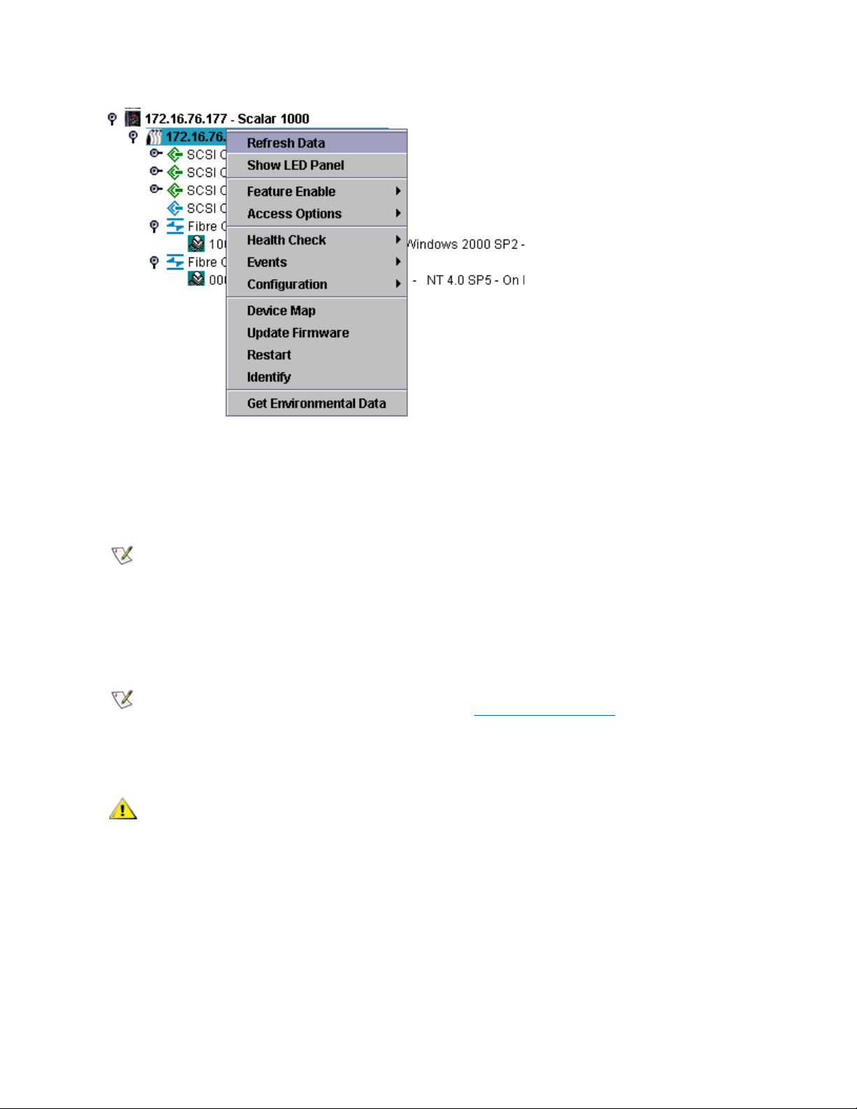
Figure 10 Right-click from the navigation panel representation of appliance
Note
Note
CAUTION
Refreshing Data
Refreshing the appliance displays host, device, and connection status changes.
After adding a device to a channel, rescan the channel and refresh data on the
appliance.
1 Right-click an appliance in the navigation panel or the graphical panel.
2 Select Refresh Data.
The displayed data will refresh.
If you have turned off trap event notices, Refresh will not turn them back on. To
turn them back on, follow the procedure in Receiving Event Traps
on page 93.
Saving and Loading the Configuration
Best practice is to save your configuration files to a folder on a server
that will be accessible at all times. Should SNC failure occur, this
allows you to quickly reconfigure a replacement.
Files that are saved when this option is chosen include the device map, Fibre Channel and SCSI port
settings, VPM, SFM, eVPS settings, and channel zoning settings. The device map is a record of the target
IDs, device LUNs, and assigned LUNs.
1 Right-click an appliance in the navigation panel or the graphical panel.
2 Select the Configuration menu, then select Save Configuration.
3 Type a name for the configuration you wish to save or select one from the list of configurations already
on the server, if any.
58 Performing Administrative Tasks
Page 67

After a few seconds the message Successfully received configuration from xxx.xxx.xxx.xxx appears in
Note
CAUTION
CAUTION
the Status/Message Area.
4 Select Save Locally.
5 A file browser opens.
It defaults to the “cfg” subfolder of the “Client” folder.
6 Select Save.
7 Select Save on Server.
After a few seconds the message Configuration file saved successfully appears in the Status/Message
Area.
It is a good idea to save the configuration both locally and on the server to
ensure that you have access to the file.
8 Select Close when you are done.
It is important that you save the configuration of each appliance
initially and any time there is a change in the device address maps,
Fibre Channel settings or SCSI channel settings.
Loading a Local Configuration File
Your service representative may advise you to load a saved file onto your SNC.
1 Right-click an appliance in the navigation panel or the graphical panel.
If you replace the appliance and do not load the saved configuration,
you might not be able to use the storage devices attached to it or you
may lose data.
2 Select the Configuration menu, then select Load a Local File.
A file browser opens to the contents of the Client folder.
3 If your local file was saved to the default location, double-click the “cfg” subfolder. Or navigate to the
appropriate location. Select the file you want to load.
4 Select Open to load the file. A message is displayed.
5 Right-click the appliance for which you’ve just loaded the configuration, either in the navigation panel or
in the graphical panel.
6 Select Restart. Refer to Using Restart
Restarting...Please Wait appears in the Status/Message Area.
on page 60.
Loading a Configuration File from the Server
Save copies of your configuration both on the server and in a location that can be accessed if the server is
unavailable.
1 Right-click an appliance in the navigation panel or the graphical panel.
2 Select the Configuration menu, then select Load from Server.
ADIC Management Console User’s Guide 59
Page 68

3 Select the file you want to load.
Note
Note
Note
4 Select Load to continue with the load.
Updating Firmware
The Update Firmware command can only be used on appliances. To update firmware on a device attached
to an appliance, refer to Managing a Device
To update firmware on any component of an i-platform library, refer to the
documentation for those systems.
1 Stop all I/O to the appliance. For instructions, refer to the Hardware User Guide for the appliance.
2 Log on as SAN administrator, portal administrator, or power user.
Basic users are not authorized to upload firmware. If the portal administrator or
power user have access to a portal with only partial access to the appliance for
which firmware is to be uploaded, only the SAN administrator can upload
firmware.
3 Right-click an appliance in the navigation panel or the graphical panel.
4 With the appliance selected, select Update Firmware.
on page 68.
A file browser is displayed.
5 If the firmware file you want is not in the default folder, navigate to the correct folder.
6 Select the file you want to load.
7 Select the Open button.
A warning is displayed.
8 Select Yes to proceed.
The firmware takes a few minutes to upload. A message posts to the Status/Message Area when the
firmware upload is complete. You are prompted to restart the appliance.
9Restart the appliance. Refer to Using Restart
.
Using Restart
Use the Restart command after updating firmware, or making changes to the device map, channel zoning,
SFM, or VPS configurations.
1 Stop all I/O to the appliance. For instructions, refer to the Hardware User Guide for the appliance.
2 Log on as SAN administrator, portal administrator, or power user.
Basic users are not authorized to restart an appliance. If the portal
administrator or power user have access to a portal with only partial access to
the appliance that is to be restarted, only the SAN administrator can restart the
appliance.
3 Right-click an appliance in the navigation panel or the graphical panel.
4 Select Restart.
A warning is displayed.
60 Performing Administrative Tasks
Page 69

5 Select Yes to continue.
Note
Select No to cancel the restart.
Restarting...Please Wait appears in the Status/Message Area.
Getting Information About a Library
Scalar Library RMU data can be accessed by right-clicking the library and selecting the Show RMU Data
command.
For more information about displaying RMU data, refer to Displaying RMU Data
I-platform libraries do not have RMUs.
.
Displaying RMU Data
Not all appliances in the SAN are capable of providing this data. If the appliance you select is not capable
of communicating this information, Show RMU Data does not appear on the appliance menu.
1 Right-click an appliance in the navigation panel or the graphical panel.
2 Select Show RMU Data.
If the appliance is capable of reporting RMU Data, but no RMU unit is attached, a dialog box is
displayed. Enter the IP address of the RMU into the dialog box.
Once connected to an RMU, information about it is displayed. The default tab is the Global Status tab.
The Mover tab provides information about library robotics.
The last tab is the Drives tab. It provides detailed information about managed drives.
3 When you are finished viewing the RMU data, select OK.
ADIC Management Console User’s Guide 61
Page 70

62 Performing Administrative Tasks
Page 71

Configuring Channels and Devices
In the course of managing your SAN, you will want to rescan or reset channels, change connection modes
and options, or update device or drive firmware. AMC has a structure in place to meet those needs. You
can also adjust the device map from the AMC.
Managing the SCSI Channel
By right-clicking a network appliance’s SCSI channel, you can directly configure SCSI channel parameters,
or instantly rescan and reset the SCSI channel. If VPM has been enabled, you can configure VPM
parameters. Refer to Enabling Licensed Features
Rescanning the SCSI Channel
Rescan the SCSI bus after adding or removing devices.
1 Expand the appliance in the navigation panel or the graphical panel.
2 Right-click the appropriate SCSI channel graphic.
3 Select Rescan.
A warning is displayed.
4 Select Yes to continue.
on page 71.
The following message is displayed in the Status/Message Area:
Rescanning SCSI Channel n on xxx.xxx.xxx.xxx. Please wait several minutes before doing a ‘Refresh.’
In this example, the “n” represents the SCSI channel number and xxx.xxx.xxx.xxx represents the IP
address of the appliance.
5 If you rescanned because you added a device, proceed to Refreshing Data
on page 58.
Resetting the SCSI Channel
Using the Reset command causes the appliance to cancel all pending commands, reset the channel, and
perform a rescan. Reset the SCSI channel after making changes to the channel configuration.
ADIC Management Console User’s Guide 63
Page 72

CAUTION
Use Reset carefully because it causes pending I/O commands to
Note
CAUTION
return failed status back to the host operating system and may have
unexpected results. Make sure all I/O is stopped before issuing this
command. For instructions on doing so, refer to the appliance’s
Hardware User Guide.
1 Expand the appliance in the navigation panel or the graphical panel.
2 Right-click the appropriate SCSI channel graphic.
3 Select Reset.
A warning is displayed.
4 Select Yes to continue.
The following message is displayed in the Status/Message Area:
Resetting SCSI Channel n on xxx.xxx.xxx.xxx. Please wait several minutes before doing a ‘Refresh’.
In this example, the “n” represents the SCSI channel number and xxx.xxx.xxx.xxx represents the IP
address of the appliance.
Configuring the SCSI Channel
The Configure command is used to change a SCSI channel’s mode, host ID, reset setting, and termination
status.
1 Log on as SAN administrator, portal administrator, or power user.
Basic users are not authorized to configure SCSI channels.
If you change any of the SCSI channel parameter settings, you must
reset the SCSI channel or reboot the appliance to use the new
settings.
2 Expand the appliance in the navigation panel or the graphical panel.
3 Right-click the appropriate SCSI channel graphic.
4 Select Configure.
The SCSI Channel Parameters dialog box is displayed.
5 Use the drop-down boxes and check boxes to make changes to the configuration as necessary.
Refer to Channel Mode
below.
6 When you are finished viewing or setting SCSI channel parameters, select OK to continue.
The following message is displayed in the Status/Message Area:
Pending changes on xxx.xxx.xxx.xxx.
, Host ID, Bus Reset on Power Up, Enable Termination,or Alternate Initiator ID,
In this example, xxx.xxx.xxx.xxx represents the IP address of the appliance.
Select Cancel to cancel all changes and return to the main screen.
7 Reset the channel. Refer to Resetting the SCSI Channel
64 Configuring Channels and Devices
on page 63.
Page 73

Channel Mode
Channel Mode identifies the channel as either an initiator or a target. When a SCSI channel is changed
from target to initiator mode, the values that appear in the host ID and alternate host ID boxes do not default
to 0. They default to values that the appliance has most recently used.
Host ID
Host ID is typically assigned as 7.
Bus Reset on Power Up
Bus Reset on Power Up is typically enabled. Removing the check mark from this box disables SCSI bus
reset on power-up.
Enable Termination
Enable Termination is typically enabled. Removing the check mark from this box disables the internal
termination circuits.
Alternate Initiator ID
The default Alternate Initiator ID is set automatically by the appliance. When the appliance scans the SCSI
bus, it determines which IDs currently are being used by target devices and sets the alternate ID to the
highest ID not in use. Change the alternate ID by using the pull-down list or typing a new number. To restore
the automatic default selection, select Automatic from the drop-down list. This option is grayed out when
the SCSI channel is being set to target mode.
Managing the Fibre Channel
By right-clicking a network appliance’s Fibre Channel, you can directly configure Fibre Channel parameters,
or instantly rescan and reset the Fibre Channel.
Rescanning the Fibre Channel
Rescan the Fibre Channel bus after adding or removing devices.
1 Expand the appliance in the navigation panel or the graphical panel.
2 Right-click the appropriate Fibre Channel graphic.
3 Select Rescan.
A warning is displayed.
4 Select Yes to continue.
The following message is displayed in the Status/Message Area:
Rescanning Fibre Channel n on xxx.xxx.xxx.xxx. Please wait several minutes before doing a ‘Refresh.’
In this example, the “n” represents the Fibre Channel number and xxx.xxx.xxx.xxx represents the IP
address of the appliance.
If you rescanned because you added a device, proceed to Refreshing Data
on page 58.
ADIC Management Console User’s Guide 65
Page 74

Resetting the Fibre Channel
CAUTION
Note
CAUTION
Using the Reset command cancels all pending commands, resets the channel, and performs a rescan. Use
this command after making changes to the channel configuration.
Use Reset carefully because it causes pending I/O commands to
return failed status back to the host operating system and may have
unexpected results. Make sure all I/O is stopped before issuing this
command. For instructions on doing so, refer to the appliance’s
Hardware User Guide.
1 Expand the appliance in the navigation panel or the graphical panel.
2 Right-click the appropriate Fibre Channel graphic.
3 Select Reset.
A warning is displayed.
4 Select Yes to continue.
The following message is displayed in the Status/Message Area:
Resetting Fibre Channel n on xxx.xxx.xxx.xxx. Please wait several minutes before doing a ‘Refresh.’
In this example, the “n” represents the Fibre Channel number and xxx.xxx.xxx.xxx represents the IP
address of the appliance.
Configuring the Fibre Channel
Fibre Channel parameters you can set are host type, loop ID, frame size, connection type, and port mode.
1 Log on as SAN administrator, portal administrator, or power user.
Basic users are not authorized to configure Fibre Channels.
If you change any of the Fibre Channel parameter settings, you must
reset the channel or reboot the appliance to use the new settings.
2 Expand the appliance in the navigation panel or the graphical panel.
3 Right-click the appropriate Fibre Channel graphic.
4 Select Configure.
The Fibre Channel Parameters dialog box is displayed.
5 Use the drop-down boxes and check boxes to make changes to the configuration as necessary. Refer
to Understanding Port Mode Options
67.
6 When you are finished viewing or setting Fibre Channel parameters, select OK to continue.
A warning is displayed.
on page 67 and Understanding Connection Type Options on page
7 Select Yes to proceed with the Reset.
The following message posts in the Status/Message Area:
Resetting Fibre Channel n on xxx.xxx.xxx.xxx. Please wait several minutes before doing a ‘Refresh.’
In this example, the “n” represents the Fibre Channel number and xxx.xxx.xxx.xxx represents the IP
address of the appliance.
66 Configuring Channels and Devices
Page 75

Understanding Port Mode Options
The Fibre Channel ports support Private and Public Fibre Channel attachments. The default port mode
setting is Public Target. You can view the settings and change port parameters.
INITIATOR
In this mode, the port operates as an initiator allowing Fibre Channel targets (disks, tape devices, or FC
switch) to attach to it.
TARGET
In this mode, the port operates as a target allowing a Fibre Channel initiator (host or FC switch) to attach to
it.
TARGET AND INITIATOR
In this mode, the appliance has access to target devices on the Fibre Channel, and initiators on the Fibre
Channel have access to targets attached to the appliance. The port operates simultaneously as a target and
initiator.
PRIVATE
With this option, the appliance scans the local loop for devices but does not check for fabric devices. Select
this option if you are connecting target devices directly to the port.
PUBLIC
With this option, the appliance scans the loop for fabric devices. If it finds a fabric device, it logs on and
queries the name server for target devices that are available on the fabric. If it finds targets attached to the
fabric, it adds all of them to the device map. Select this option if you are connecting a Fibre Channel switch
to the port and you want the appliance to have access to all of the available target devices attached to the
switch. Otherwise, if target devices are connected directly to the port, it automatically switches to Private
mode.
Understanding Connection Type Options
The Fibre Channel ports support both Loop and Point-to-Point connection options. The default connection
setting is Loop.You can view the settings and change port parameters.
LOOP
With this connection option, the port operates with attached loop-capable devices. If a point-to-point device
is attached, the appliance is not able to communicate with it.
POINT-TO-POINT
With this connection option, the port supports point-to-point fabric connection (F_Port Login). It also
operates in “old port mode” for compatibility with N_Port devices that do not support Loop. If loop-capable
devices are attached, the appliance is not able to communicate with them.
LOOP PREFERRED
With this connection option, the port operates in Loop mode unless it detects a connection to an N_Port
device in which case it automatically switches to Point-to-Point.
ADIC Management Console User’s Guide 67
Page 76

Host Type
Note
Host Type has many possible values: AIX, AS400, Gateway, HP-UX, Linux, NT (includes Windows 2000,
XP, and 2003), Netware, Generic, Solaris, and Autosense/NT (same as “NT”). Hosts running other
operating systems use the setting Generic. The default setting is NT. The host type is either the name of
the host operating system or the type of appliance attached to the port. This setting controls the way the
appliance translates SCSI commands, such as the format of SCSI sense data, which needs to be presented
differently for some hosts. If eVPS OR SFM is enabled, the host type setting in the eVPS OR SFM control
panel are used instead of this setting.
Loop ID
The default Loop ID setting is Soft and typically should not be changed. (It may be appropriate to use
another Loop ID setting when using Fibre Channel switches). If you remove the check mark from the box,
you can type a Loop ID value from 0 to 125.
Frame Size
Frame size has three possible values: 512, 1024, and 2048. The Fibre Channel frame size is specified by
each receiving node and need not match any other node. The frame size typically should be set to 2048. (It
may be appropriate to use another frame size if required by a particular software application.)
Managing a Device
You can use AMC to update firmware on devices and edit device maps. To update firmware on the
appliance, refer to Updating Firmware
on page 60.
Updating Firmware on a Device
1 Stop all I/O to the device. For instructions, refer to the appliance’s Hardware User Guide.
2 Log on as SAN administrator, portal administrator, or power user.
Basic users are not authorized to upload firmware. If the portal administrator or
power user have access to a portal with only partial access to the appliance for
which firmware is to be uploaded, only the SAN administrator can upload
firmware.
3 Expand the appliance in the navigation panel or the graphical panel. Expand the appropriate channel.
4 Right-click the device graphic.
5 Select Update Firmware.
A file browser is displayed.
If the firmware file you want is not in the default folder, navigate to the correct folder.
6 Select the file you want to load.
7 Select the Open button.
A warning dialog box is displayed.
Be sure all I/O to the device has been stopped.
8 Select Yes to proceed.
68 Configuring Channels and Devices
Page 77

If I/O to the device cannot be stopped, or if you change your mind, select No to cancel the firmware
Note
CAUTION
Note
upload.
After the firmware upload is complete, you will be prompted to Restart the appliance. Refer to Using
Restart on page 60.
Editing Device Maps
Some applications require LUNs to be presented in an order other than the order that the discovery routine
presents them to the SNC.
1 Log on as SAN administrator, portal administrator, or power user.
Basic users are not authorized to configure the device map. If the portal
administrator or power user have access to a portal with only partial access
to the device mapping configuration, only the SAN administrator can modify
access.
2 Right-click the appliance in the navigation panel or the graphical panel.
3 Select Device Map.
Making changes to LUN assignments in the persistent address map
database can affect SFM, eVPS, and VPM access settings. If you
assign different LUNs to devices that are under access control by
more than one of these methods, the same LUN could become
associated with different devices and data would be lost.
The Device Mapping dialog box is displayed.
The Device Mapping dialog box uses the device numbering format “Channel [Target ID:Device LUN]”
after the channel type, “SCSI” or “Fibre.”
Grayed-out images of these same devices, without the assigned LUNs, appear in the right column.
LUN 0 typically is occupied by the appliance’s “Control LUN,” unless it has been manually assigned to
another LUN.
Devices are assigned LUNs by the initial discovery. They appear in black type on the left.
4 To reassign the LUN, drag a device that is displayed in the left column back to the right column or
directly to another space in the left column.
The right column can temporarily hold an item while you scroll to an appropriate
open space in the left column, but no items can be left in the right column. They
must all be mapped to an assigned LUN position in the left column.
To delete a device, drag and drop it onto the trash can icon.
5 Continue until all devices are assigned.
6 When you are satisfied with the assignments that have been made, select OK.
7 Restart the appliance. Refer to Using Restart
8 Reboot the host, or use some other method to ensure that the host is aware of the new device map.
on page 60.
ADIC Management Console User’s Guide 69
Page 78

Pre-Assigning Device Numbers
The New Device command is used to assign a LUN to a device that is currently not present on the system,
but for which a soft LUN—a LUN registered by the SNC during discovery—is not adequate.
A medium-changer will typically be the first odd numbered LUN (1) if available, or the first odd LUN available
after the last tape.
Particular applications or tools may require settings that are different than the defaults. To hard-code a
particular LUN for a particular device, add it into the device map first. Then bring the device online.
Devices usually come online before the SNC does. When the SNC boots up, it scans all devices and
determines where they are. At the end of the boot process, the appliance knows the LUNs available and is
ready to use them.
1 Right-click an appliance in the navigation panel or the graphical panel.
2 Select Device Map.
3 Select the Device Mapping dialog box, point to the Tools menu, then select New Device.
The default new device is a SCSI device on port (channel) 1, at target ID 0, and target LUN (device
LUN) 0.
4 Use the pull-downs at the end of each field to identify the device appropriately.
If the device to be added is a Fibre Channel device, you must supply the correct Unit ID.
5 Select OK.
The new device or devices is displayed in the right column of the Device Mapping dialog box.
6 Drag and drop the new device to a LUN assignment.
7 Select OK.
8 Rescan the channel.
Refer to either Rescanning the SCSI Channel
65, as appropriate.
9 Rediscover the network segment. Refer to Discovering the SAN
10 Refresh data on the appliance. Refer to Refreshing Data
on page 63 or Rescanning the Fibre Channel on page
on page 55.
on page 58.
70 Configuring Channels and Devices
Page 79

Configuring SAN Access
Note
In addition to providing security via user privilege assignments, AMC allows you to configure SAN access
for a particular channel or group of LUNs, or from a particular host perspective.
Enabling Licensed Features
Use the Feature Enable menu to enable licensed features for the selected appliance. Features that must
be enabled before you use them are:
• Scalar
• extended Virtual Private SAN
• Virtual Private Map (VPM)
• Data Mover Module
1 Right-click an appliance in the navigation panel or the graphical panel.
2 Select Feature Enable menu. From the submenu that opens, elect the functionality you want to enable.
®
Firewall Manager (SFM)
®
(eVPS)
If the feature is already enabled or not available, the menu item is grayed out
on the menu bar.
If a feature is already enabled or not available for a particular appliance, it is grayed out on the menu.
3 Type the license key for the feature you are enabling. If the feature has been factory enabled, type the
word enable.
4 Select OK to continue.
5 If you enabled SFM, proceed to Using Scalar Firewall Manager (SFM)
If you enabled eVPS, proceed to Using eVPS
If you enabled VPM, proceed to Using VPM
If you enabled the Data Mover Module, you do not need to adjust other settings.
ADIC Management Console User’s Guide 71
on page 80.
on page 86.
on page 76.
Page 80

Data Mover Module
Note
Note
CAUTION
Basic users are not authorized to enable the Data Mover Module. For user
privileges, see Table 1
The data mover module allows you to use server-free tape backup applications that support SNIA extended
SCSI copy. Enabling this feature allows the appliance to move blocks of data directly between storage
devices attached to it.
on page 36.
Using Channel Zoning
Channel zoning (also called “port zoning”) configures access to an entire target channel and all the LUNs
on that channel for the exclusive use of a host or group of hosts on a single initiator channel. Each initiator
channel can connect a maximum of 64 hosts.
A LUN (Logical Unit Number) is a 3-bit identifier used on a SCSI bus to distinguish between as many as
eight devices with the same SCSI ID.
In a situation where the devices are tape devices and more than one host is connected to the initiator
channel, the tape library application typically manages host requests to the zoned channel.
1 Log on as SAN administrator, portal administrator, or power user.
Basic users are not authorized to configure channel zoning. If the portal
administrator or power user have access to a portal with only partial access to
the channel zoning configuration, only the SAN administrator can modify
access.
2 Right-click an appliance in the navigation panel or the graphical panel.
3 Select the Access Options menu, then select Channel Zoning.
The default settings allow all SAN connections to access all target channels.
4 Select the check boxes to remove or create restricted access zones for the desired SAN connections
and target channels.
All combinations are possible.
Bear in mind that an entire channel is zoned when the box is checked.
If you make changes to the channel zoning settings you must restart the appliance for the new settings
to take effect.
5 To copy or print a text file of your channel zoning settings, select the Tools menu on the Channel
Zoning dialog box. Then select Copy Channel Zoning or Print Channel Zoning.
If you create restricted access zones with channel zoning, then SFM,
eVPS, and VPM can only assign access permission within each
accessible zone. For more information refer to Using Scalar Firewall
Manager (SFM) on page 76, Using eVPS on page 80, or Using VPM on
page 86.
6 Select OK to proceed with any changes you made.
Select Cancel to leave channel zoning unchanged.
72 Configuring SAN Access
Page 81

Installing HRS
Note
Note
Note
The Host Registration Service (HRS) presents host information that SNCs and MCBs use to manage host
access and data retrieval. The information that is presented includes host name, host type, host connection
and the online or offline status. This information is sent periodically over the host Fibre Channel connection.
The default HRS setting re-registers the host every 5 minutes. You can change the re-registration period to
any value between 1 and 255 minutes.
Once HRS is installed, you can get help by typing
hrs -h
on the command line, and then pressing Enter.
AMC uses HRS to facilitate use of SFM, eVPS, and VPM, which are LUN mapping schemes. For more
information about them, refer to Using Scalar Firewall Manager (SFM)
80, and Using VPM
on page 86.
If you plan to use SFM, eVPS, or VPM install HRS on the appropriate hosts. If
you do not plan to use SFM, eVPS, or VPM you can manage your SAN without
installing HRS. However, HRS insures that data path conditioning includes the
host portion of the data path.
Installing the Host Registration Service for Windows
Install this software on a host computer running the Windows operating system that is attached to an SNC,
MCB or network chassis.
on page 76, Using eVPS on page
1 Verify that the Windows host you are configuring has an installed Host Bus Adapter (HBA).
2 Obtain HstRegSrv.exe from your service representative.
3 Select the Windows Start button, and then select Run.
4 Point to HstRegSrv.exe.
5 Select OK.
6 Once installation completes, reboot the system.
HRS executes as a service and therefore launches at boot time.
On a Windows system, the re-registration period cannot be changed, because
HRS runs as a service rather than an independent program.
Installing the Host Registration Service for Solaris
Install this software on a host computer running the Solaris operating system that is attached to an SNC,
MCB or network chassis.
You must uninstall previous versions of HRS on Solaris before installing a
newer version.
1 Verify that the Solaris host you are configuring has an installed Host Bus Adapter (HBA).
2 Obtain HstRegSrv.tar from your service representative.
ADIC Management Console User’s Guide 73
Page 82

3 From the command line type
ps -A | grep hrs
and press Enter.
If a previous version of HRS is found, a message similar to the following displays:
<219 ? 0:00 hrs>
4 If no messages similar to the output in Step 3
If a similar message displays, type
pkgrm <package name>
and press Enter.
5 If you removed a package, reboot the host:
reboot -- -r
6 Load the product CD into the Solaris host.
7 Find the HstRegSrv.tar file.
8 Copy HstRegSrv.tar to a temporary directory.
9 From the directory that has HstRegSrv.tar in it, type:
tar xf HstRegSrv.tar
and press Enter.
10 Type the following command:
pkgadd -d .
and press Enter.
11 Type the following command:
reboot -- -r
display, proceed to Step 6.
and press Enter.
HRS runs when the system is booting. The file that controls this process is S99hrs and it can be found
in the folder /etc/rc2.d
The default re-registration period is 5 minutes.
Changing the re-registration period
1 Find the PID for the current HRS process. Type
ps -ef | grep hrs
and press Enter.
2 Kill the HRS process. Type
kill -9 [PID]
and press Enter.
3 Restart HRS. For the phrase in brackets, substitute the number of minutes you want to elapse between
registrations. Type:
hrs -i[interval in minutes] -D &
and press Enter.
This causes HRS to run in the background as a daemon, registering at the specified time interval.
74 Configuring SAN Access
Page 83

Installing the Host Registration Service for HP-UX
Install this software on a host computer running the HP-UX operating system that is attached to an SNC,
MCB or network chassis.
1 Verify that the HP-UX host you are configuring has an installed Host Bus Adapter (HBA).
2 Obtain HstRegSrv.depot from your service representative.
3 From the command line type
sam
and press Enter.
4 Select the Software Management menu, then select Install Software on the Local Host.
5 After Source Host Name: type your host’s name.
6 After Source Depot Path: type the name of the directory that contains the *.depot file.
Type the full file name, HstRegSrv.depot
7 Select OK.
8 Select the Action menu, then select Install (analysis...)
9 At the confirmation window select Yes.
10 Select Done when Installation completes.
HRS is located in /usr/contrib/bin
11 Reboot.
12 Optionally, change the re-registration period, by typing
hrs -i[interval in minutes] -D &
and press Enter.
This causes HRS to run in the background as a daemon, registering at the specified time interval.
The default re-registration period is 5 minutes.
Installing the Host Registration Service for AIX
Install this software on a host computer running the AIX operating system that is attached to an SNC, MCB
or network chassis.
1 Verify that the AIX host you are configuring has an installed Host Bus Adapter (HBA)
2 Obtain HstRegSrv.bff from your service representative.
3 From the command line type
smit
and press Enter.
4 Select the Software Installation and Maintenance menu, point to Install and Update Software.
Then select Install and Update Software by Package Name (includes devices and printers).
5 Type the path to the HstRegSrv.bff file at the command prompt, or select the List button on the right
side of the screen to select this file.
If you are entering the path, be sure you include the HstRegSrv.bff as the file name.
6 When prompted to Select Packages to List, select package.
7 When prompted to Select Software to Install, select 1.13.0.0 ADIC Host Registration Service
ADIC Management Console User’s Guide 75
Page 84

The software installs.
Note
Note
8 Reboot.
9 Optionally, change the re-registration period, by typing
hrs -i[interval in minutes] -D &
and press Enter.
This causes HRS to run in the background as a daemon, registering at the specified time interval.
The default re-registration period is 5 minutes.
Installing the Host Registration Service for Linux
To install HRS, perform the following steps:
1 Obtain the HRS file from the website or from your customer service representative.
2 At the command line, type rpm -i HostRegServ-2.0-x.i386.rpm
3 Reboot the host.
The HRS utility will start when the system is booting.
If you reinstall the HRS utility, you must uninstall previous versions first. Use the following procedure:
1 At the command line, type ps -ef | grep hrs
This command outputs the process ID.
2 At the command line, type kill -9 (process id)
At the command line, type rpm -e HostRegServ
Using Scalar Firewall Manager (SFM)
Scalar® Firewall Manager (SFM) is a software feature that collects all host and target information and
manages the end-to-end access control in the SAN. It allows the system administrator to control access
privileges between individual Host Bus Adapters (HBAs) and target devices connected to the appliance’s
SCSI and Fibre Channels.
If you are using an SNC outside of a Scalar library, the SFM feature is called
Virtual Private SAN (VPS). To use VPS, you can still follow these instructions.
Wherever the instructions specify “SFM,” substitute “VPS.”
SFM provides you with a finer degree of access control than channel zoning. The Channel Zoning feature
allows you to map an entire channel to specified host or hosts. SFM maps selected LUNs on selected
channels to a specified host or hosts on a SAN-wide basis.
SFM can be used to allow multiple Fibre Channel hosts connected via switches and hubs to be able to share
the same SCSI or Fibre Channels while restricting their access to selected LUNs on those channels.
Using SFM does not require the purchase of a license when used to manage access control in SANs
consisting of ADIC FC libraries.
When you migrate to extended VPS (eVPS) your mappings must be managed
through eVPS. The SFM screen is disabled as a result of the migration.
76 Configuring SAN Access
Page 85

Installing SFM
Note
Installation of SFM into a system with a developed SAN is different than installation of SFM into a new
system.
1 Log in as SAN administrator, portal administrator or power user.
Basic users are not authorized to configure SFM. If the portal administrator or
power user have access to a portal with only partial access to the SFM
configuration, only the SAN administrator can modify access.
2 If you want to install the host registration service (HRS) on the hosts that are involved, consult your
service representative.
3 If you are installing SFM as part of a new SAN installation, proceed to Step 4
existing SAN, proceed to Step 5
4 If you are installing SFM into a pre-existing SAN, follow these steps:
a. Install HRS on the hosts.
b. Leave the hosts running.
c. Enable SFM. Refer to Enabling Licensed Features
d. Right-click the appliance with SFM enabled.
e. Select Refresh Data. Refer to Refreshing Data
f. Proceed to Step 6
5 If you are installing SFM into a new SAN, follow these steps:
a. Load HRS onto the hosts.
b. Shut the hosts down.
c. Restart the appliance. Refer to Using Restart
d. Start up the hosts.
e. Enable SFM. Refer to Enabling Licensed Features
f. After the hosts are finished booting, right-click the appliance with SFM enabled.
g. Select Refresh Data. Refer to Refreshing Data
.
on page 71.
on page 58.
.
on page 60.
on page 71.
on page 58.
. For installation into a pre-
h. Proceed to Step 6
6 Expand all node symbols to display all hosts, devices and their assigned LUNs. Refer to Device
Numbering on page 30.
.
Configuring Access Through SFM
Configure access to certain LUNS for certain hosts. Other hosts will no longer see those LUNs.
1 Make a list of which LUNs you want to assign to which hosts.
2 From the navigation panel or the graphical panel, right-click the appliance with SFM enabled.
3 Select the Access Options menu, select Scalar® Firewall Manager.
The Scalar® Firewall Manager Access Settings dialog box is displayed. See Figure 11
ADIC Management Console User’s Guide 77
on page 78.
Page 86

Figure 11 Scalar Firewall Manager access settings dialog box
Note
Figure 11
Registered hosts are shown in the column on the left. When a host is online its name is displayed in
black.
When a host is registered but not currently online its name is displayed in blue.
To have complete host information appear in the display, you must first be running HRS. Consult your
service representative.
4 Select the Assigned LUN check boxes to indicate that access is enabled between a LUN and the
corresponding host. Select again to revoke access.
shows labeled components of the Scalar® Firewall Manager Access Settings dialog box.
Hover the mouse over a LUN or a host in order to have details about it display
in a blue popup.
• To select or deselect access to every LUN in a particular host’s line, use the Select All or
Deselect All buttons located on the right side of the screen.
78 Configuring SAN Access
Page 87

• To select or deselect access to all LUNs for a host, find the host’s name in the list of hosts in
the upper left corner of the screen and select it. Then select Select All or Deselect All.
Figure 12
accessing.
Figure 12 LUNs restricted for selective access by four hosts
on page 79 shows LUNs assigned so that no host can access LUNs that any other host is
5 Select Apply to keep the changes you made to host data fields and LUN assignments.
Select Undo button to cancel all changes since the last time Apply was used.
Select the Close button to close the dialog box, or select the x button in the upper right corner of the
dialog box. If you made changes, a confirmation box presents you with the option of not closing until
you apply the changes.
Select Help if you want context-sensitive help.
6 Save your configuration. Refer to Saving and Loading the Configuration
on page 58.
Adding SFM Hosts
Hosts can be added to the SAN after initial SFM configuration.
1 Select the New Host button to add a new host to the system manually.
The text boxes in the lower left corner of the screen become available. If you do not have the data for
these fields, let the host registration service (HRS) discover the data for you. Talk to your service
representative about installing this software.
2 Fill in Host Name and other information.
ADIC Management Console User’s Guide 79
Page 88

• Select the correct Host Type, which is the operating system or appliance type, from the Host
Note
CAUTION
Type drop-down list.
•The Host Connection consists of the port number that the host attaches to, the host’s IP
Address, and information about the HBA.
• You must know the host’s World Wide Name to add it manually.
3 When you are finished, select either Accept New Host or Quit New Host.
4 Select the Apply button to keep the changes you made to host data fields and LUN assignments.
5 Save your configuration. Refer to Saving and Loading the Configuration
on page 58.
Deleting SFM Hosts
Hosts can be removed from the SAN after initial SFM configuration.
1 Select the host’s name in the SFM Access Settings dialog box.
In Figure 12
If the host is currently online, you cannot delete it until you select the Take Host Off Line button.
Once a host is selected, information about it is displayed in the bottom portion of the dialog box.
2 Select the Delete a Host button.
3 Select the Apply button to keep the changes you made to host data fields and LUN assignments.
Select the Undo button to cancel all changes since the last time Apply was used.
Select the Close button to close the dialog box, or select the x button in the upper right corner of the
dialog box. If you made changes, a confirmation box presents you with the option of not closing until
you apply the changes.
4 Save your configuration. Refer to Saving and Loading the Configuration
on page 79, the hosts online are Genesee, Alison, and Timberline.
on page 58.
Using eVPS
The access control you achieve with SFM for SAN-wide LUN mapping can be extended to per-host LUN
mapping using eVPS (extended Virtual Private SAN).
When you migrate to eVPS, your mappings must be managed through eVPS.
The SFM screens are disabled as a result of the migration.
You can achieve faster, cleaner management access to mapped LUNs with eVPS. All hosts see the LUNs
to which they have access beginning at LUN 1, rather than beginning at a potentially very high LUN number
that is the device’s actual LUN. Like SFM, eVPS can be used to allow multiple Fibre Channel hosts
connected via switches and hubs to be able to share the same SCSI or Fibre Channels while restricting their
access to selected LUNs on those channels.
• Use eVPS to map LUNs to hosts on a per host basis.
• The total number of LUNs that can be mapped is 2048.
• The total number of LUNs that can be mapped per host is 256.
Using eVPS requires you to purchase a license.
Windows Server products only support up to 254 LUNs per Target ID.
80 Configuring SAN Access
Page 89

Installing eVPS
Note
CAUTION
Installation of eVPS into a system with a developed SAN is different than installation of eVPS into a new
system.
Basic users are not authorized to configure eVPS. If a portal administrator or
power user has access to a portal with only partial access to the eVPS
configuration, only the SAN administrator can modify access.
1 Log on as the SAN administrator, portal administrator, or power user.
If you have made channel zoning assignments, review them to be
sure they do not conflict with eVPS assignments. If your SAN has a
large number of hosts, it is not recommended that channel zoning be
run simultaneously with eVPS.
2 If you want to install the host registration service (HRS) on the hosts that are involved, consult your
service representative.
3 If you are installing eVPS as part of a new SAN installation, proceed to Step 5. For installation into a
pre-existing SAN, proceed to Step 4
4 If you are installing eVPS into a pre-existing SAN, follow these steps:
a. Install HRS on the hosts.
.
b. Leave the hosts running.
c. Enable eVPS. Refer to Enabling Licensed Features
d. Right-click the appliance with eVPS enabled.
e. Select Refresh Data. Refer to Refreshing Data
f. Proceed to Step 6
5 If you are installing eVPS into a new SAN, follow these steps:
a. Load HRS onto the hosts.
b. Shut the hosts down.
c. Restart the appliance. Refer to Using Restart
d. Start up the hosts.
e. Enable eVPS. Refer to Enabling Licensed Features
f. After the hosts are finished booting, right-click the appliance with eVPS enabled.
g. Select Refresh Data. Refer to Refreshing Data
h. Proceed to Step 6
6 Expand all node symbols to display all hosts, devices and their assigned LUNs. Refer to Device
Numbering on page 30.
.
.
on page 71.
on page 58.
on page 60.
on page 71.
on page 58.
Configuring Access Through eVPS
Configure access to certain LUNS for a particular host, beginning the LUN numbering at 1. The host will no
longer have to scan the full bus in order to see devices with high LUNs to which it has access. Those LUNs
will appear to the host as if their numbering begins at 1. Once mapping is complete, other hosts will no
longer see LUNs mapped to a particular host. There are two perspectives from which to do this mapping:
ADIC Management Console User’s Guide 81
Page 90

• From the appliance’s perspective
• From the host’s perspective
Assigning LUNs to host(s) using the appliance perspective
1 Make a list of which LUNs you want to assign to which host(s). A maximum of 64 hosts can be
connected to a Fibre Channel.
2 Right-click the appliance with eVPS enabled.
3 Select the Access Options menu, select Extended Virtual Private SAN®.
The eVPS Access Settings dialog box is displayed. See Figure 13
Figure 13 eVPS mappings for internal LUNs 0-9
.
Compare the Internal LUNs in Figure 13
on page 83.
82 Configuring SAN Access
to the assigned LUNs in the navigation panel shown in Figure 14
Page 91

Figure 14 Assigned LUNs 1-9 in the navigation panel
In Figure 13
name is displayed in black. When a host is registered but not currently online its name is displayed in
blue.
The number in the “Internal LUN” row is in black if a LUN is online. Otherwise the Internal LUN number
is grayed out.
To have complete host information appear in the display, you must first be running HRS. Consult your
service representative.
4 Type a number into an Internal LUN check box to indicate that access is enabled between a LUN and
the corresponding host.
Delete the number to revoke access.
In Figure 13
5 Select the OK button to keep the changes you made to host data fields and LUN assignments.
Select the Cancel button to cancel all changes.
Select the Help button to get context-sensitive help.
6 Save your configuration. Refer to Saving and Loading the Configuration
on page 82, registered hosts are shown in the column on the left. When a host is online its
on page 82, each host has had LUNs mapped to it that it will see as LUNs 0-3.
on page 58.
Assigning LUNs to host(s) using the host perspective
1 Select the Host LUN Mapping command from the Host menu on the eVPS Access Summary dialog
box.
The Host LUN Mapping dialog box is displayed. See Figure 15
ADIC Management Console User’s Guide 83
on page 84.
Page 92

Figure 15 Host LUN mapping
The host LUN mapping in Figure 15
Figure 13
to Internal LUNs 0, 1, 2, and 4.
2 Make any necessary changes.
3 Select OK.
The View command on the Host LUN Mapping dialog box operate as a toggle, in the same way that
the View menu operates on the eVPS Access Summary dialog box.
Refer also to Using the eVPS View Menu
on page 82 to the host LUN map in Figure 15 . The host LUNs 0-3 in Figure 15 correspond
is for the host named “Asahi.” Compare the mapping displayed in
on page 85.
Adding or Modifying eVPS Hosts
Hosts can be added to the SAN after initial eVPS configuration.
1 Select Add Host or Modify Host from the Host menu on the eVPS Access Summary dialog box.
2 Fill in Host Name, Host Type, Host Connection, and Host WWN.
Refer to Adding SFM Hosts
Configuration dialog box is used to let AMC know about hosts that are using SFM.
3 Select the OK button to keep the changes you made to host data fields and LUN assignments.
4 Save your configuration. Refer to Saving and Loading the Configuration
on page 79 for details on filling out these fields. The eVPS Host
on page 58.
84 Configuring SAN Access
Page 93

Deleting eVPS Hosts
CAUTION
Hosts can be removed from the SAN after initial SFM configuration.
Be sure the host that you want to delete is offline. Offline hosts are
shown in blue.
1 If the host is not offline, select Take Host Offline from the Host menu on the eVPS Access Summary
dialog box.
2 Select Delete a Host from the Host menu on the eVPS Access Summary dialog box.
3 Select OK to proceed with the host deletion.
4 Save your configuration. Refer to Saving and Loading the Configuration
on page 58.
Using the eVPS View Menu
The Show Details and Show All LUNs commands are used to get quick info on the eVPS device map.
Check and uncheck the boxes in front of the toggled choices Show Details and Show All LUNs under the
View command on the eVPS Access Summary dialog box.
Figure 16
the LUNs under eVPS control, respectively.
Figure 16 eVPS Show all LUNs command
and Figure 17 on page 86 illustrate a view of all LUN space available to eVPS and a view of only
ADIC Management Console User’s Guide 85
Page 94

Figure 17 eVPS Do Not Show All LUNs command
Note
CAUTION
Using VPM
VPM (Virtual Private Map) allows a SCSI attached host to map Fibre Channel devices to Fibre Channel
LUNs.
If you have made channel zoning assignments, review them to be sure they are not in conflict with VPM
assignments. It is not recommended that channel zoning be run simultaneously with VPM.
Preparing to Use VPM
1 Log on as the SAN administrator or portal administrator.
Basic users and power users are not authorized to configure VPM.
2 If you want to install the host registration service (HRS) on the hosts that are involved, consult your
service representative.
3 Right-click the SCSI channel where the host is attached.
4 Change SCSI channel port mode to Target. Refer to Configuring the SCSI Channel
Do not forget to reset the channel, which is the last step in the
Configure SCSI channel procedure.
on page 64.
5 Reboot the host.
6 Enable VPM. Refer to Enabling Licensed Features
86 Configuring SAN Access
on page 71.
Page 95

Making VPM assignments
Note
1 Right-click the SCSI channel that has been set to Target.
2 Select Virtual Private Map.
If you right-click a SCSI channel not set to Target, or if you have not enabled
VPM, the VPM command on the selected SCSI channel is not available.
The VPM dialog box opens.
The ID/LUN/Device column of the VPM display provides map space for IDs 0-15 associated with the
selected SCSI channel, LUNs 0-7 associated with each ID, and a box into which a device from the
Device column can be dragged and dropped in order to occupy a particular ID and LUN on the SCSI
host channel. For information about device numbering, refer to Device Numbering
Drag and drop the devices from the Device column to the appropriate LUN in the ID/LUN/Device
column.
When a target device has been mapped, it is displayed in gray in the Device column.
To see the grayed out images of the Fibre Channel devices, scroll the Device column down to the
higher LUN range to which these devices were mapped during discovery.
3 Select OK to save mapping.
The VPM map is automatically saved as part of the configuration.
The message Made Virtual Private Mapping changes appears in the Status/Message Area.
on page 30.
ADIC Management Console User’s Guide 87
Page 96

88 Configuring SAN Access
Page 97

Troubleshooting the SAN
This section references event codes and error messages that may appear in the event trap window or the
event log maintained by the AMC server. For in-depth maintenance, repair, and troubleshooting information
refer to the maintenance manual for your library or the hardware guide for your SNC.
Monitoring and Managing Event Logs
For libraries that have an SNC, submenus under Events allow you to control the way the event log is
displayed and how traps are generated. Traps (messages) are generated when an event occurs at a
specific frequency. Refer to Setting the Event Trap Threshold
the policy engine, so that you receive e-mail notices about trap event conditions. Refer to Configuring
Policies on page 54.
1 Right-click an appliance in the navigation panel or the graphical panel.
2 Select the Events menu, then select View Event Log.
The event reporting level is displayed.
3 Select Warning to display Warning and Notice events.
Select Information to display Information, Warning and Notice events.
Selecting All Events is equivalent to selecting Information.
on page 93. Events can also be managed by
4 Select OK to continue. If you selected OK, the event log is displayed. Use scroll bars to navigate
through the log.
a. Click, shift-click, control-click to select all or some of the events in the event log, or from the Edit
menu, select Select All.
b. To copy the selected events to a text file, select the Edit menu, then select Copy.
c. To save events to a text file, select the File menu, then select Save.
Printing the Event Log
1 Follow the procedure in Monitoring and Managing Event Logs.
2 With the event log window displayed, select the File menu, then select Print.
The printer dialog box opens.
3 Confirm that the log be sent to your printer.
By default, all pages are sent to the printer.
ADIC Management Console User’s Guide 89
Page 98

• If you do not want to print all the pages of a lengthy event log, click, shift-click and/or controlclick to select the lines you want to print.
• Paste this text into a file editor.
• Select the File menu, then select Print.
Saving a Copy of Currently Displayed Entries
1 Right-click an appliance in the navigation panel or the graphical panel.
2 Select the Events menu, then select Save Event Log.
3 Type a name for the file in the browser dialog box.
If you do not want to save the file to the default location, browse to a new location.
4 After the log is saved, you are asked if you want to clear the event log on the selected appliance.
Select Yes to clear the event log.
Select No to preserve the event log as is.
Interpreting the Event Log
Use Table 2 to interpret listed events. Make a note of pertinent event codes and refer to the SNC Firmware
4 Reference Guide for troubleshooting actions.
If there are no abnormal events, but behavior is still unacceptable, proceed to Performing Health Check
page 98.
Table 2 Event Codes and Actions
Event
Code
8 Sense data recorded following a check condition.
Note: Normally, the host system will request and process sense data and then
perform error recovery.
9 LUN reports a “unit attention” condition on a non-removable media device
11 SNC reports a temperature change (event message indicates the change to high,
very high, reduced to high, or OK)
13 Appliance is shutting down as requested by AMC
(a Restart was requested)
14 Additional status information used for diagnostics
16 A SCSI bus reports an unexpected interrupt
17 Fibre Channel interface reports a LIP reset was received from a host
Description
on
18 Fibre Channel interface reports a system error
19 Fibre Channel interface reports an error processing a request
20 Fibre Channel interface reports an error processing a response
21 Appliance processor memory fault detected
22 Fibre Channel interface detected a LIP
90 Troubleshooting the SAN
Page 99

Table 2 Event Codes and Actions (Continued)
Event
Code
Description
23 Fibre Channel interface reports a loop up
24 Fibre Channel interface reports a loop down
25 Appliance PCI bus parity error detected
26 Appliance PCI interface error detected
27 A device has been added to a SCSI bus
28 A SCSI bus reports a reset has been detected
29 Appliance has added a device to its configuration table
Note: The trap is delayed until the appliance has been up for 60 seconds.
30 Appliance has removed a device from its configuration
31 Appliance logging service has started
33 An interface has detected a bus fault
(event message indicates the specific interface)
34 An interface has detected a device fault
(event message indicates the specific interface)
35 A SCSI interface reported an unexpected disconnect by a device
36 A parity error was detected on a SCSI bus
37 Fibre Channel port database change detected
39 Directory Server on fabric has changed
40 Maximum LUN limit has been exceeded
41 Fibre Channel transfer failure
Note: Error recovery may have succeeded.
42 Maximum device limit has been exceeded (persistent address map database is full)
43 Fibre Channel interface driver reported debug file dump (event log contains further
information)
58 Power has returned to nominal from warning or alarm stage
59 Power has entered warning range from nominal range (power falling) or alarm range
(power improving)
60 Power has entered alarm range
61 Inlet air, outlet air, or I/O processor temperatures have entered nominal range from a
warning or alarm range
62 Inlet air temperature has entered warning range from nominal range (heating up) or
alarm range (cooling down)
63 Inlet air temperature has entered alarm range
64 Outlet air temperature or I/O processor temperature has entered warning range from
nominal or alarm ranges
ADIC Management Console User’s Guide 91
Page 100

Table 2 Event Codes and Actions (Continued)
Event
Code
Description
65 Outlet air temperature or I/O processor temperature has entered alarm range
66 Fan is operating in nominal range after operating in a fault state
67 Fan speed has entered warning range (tachometer fans only)
68 Fan speed has entered alarm range (tachometer fans) or is stalled (rotor stall fans)
70 Appliance restart completed
71 Firmware upload completed
72 More than 64 initiators per FC Channel
73 Data path failover has occurred at FCn WWPN=nnnnnnnn:nnnnnnnn lun=nxn
loopId=nxn
75 Host has gone offline.
76 Has has come online.
150 The event log is about to overwrite the earliest events
Health Check Event Descriptions
100 Power supply is out of specification
102 Temperature change detected since the last report (event message indicates the
change to high, very high, reduced to high, or OK)
106 Fibre Channel interface failed health check
107 SCSI interface failed health check
109 Target device failed health check
110 Fibre Channel link status changed
111 Fibre Channel transfer failures detected since the last report
Note: Error recovery may have succeeded.
112 Blower/Fan is running in warning or alarm range
113 Power is running in warning or alarm range
114 Temperature is running in warning or alarm range
115 Network is running at 10 Mb/sec
Heartbeat Event Descriptions
Note: These event codes are not logged in the event log. Notification of these events
occurs from AMC.
200 The server could not verify the connection to the appliance
201 The client could not communicate with the server
202 The server could not communicate with the Client
203 Heartbeat communication restored
92 Troubleshooting the SAN
 Loading...