

Page 1

ACL 4/52 Automated Tape Library
for DLT Cartridges
Operator’s Guide
6211222-05
Ve r. 5, Rel. 0
Page 2

ACL 4/52 Operator’s Guide, 6211222-05, Ver. 5, Rel. 0, January 2000. Printed in the USA.
ATL Products, Inc. pr ov ides th is pub lic at ion “as i s” without warranty of any kind, either express or implied, including but
not limited to the implied warranties of merchantability or fitness for a particular purpose. ATL Products, Inc. may revise
this publication from time to time without notice.
COPYRIGHT STATEMENT
Copyright 2000 by ATL Products, Inc. All rights reserved.
Your right to copy this manual is limited by copyright law. Making copies or adaptations without prior written
authorization of ATL Products, Inc. is prohibited by law and constitutes a punishable violation of the law.
TRADEMARK STATEMENT
Prism Library Architecture, IntelliGrip, WebAdmin, and WebLibrarian are all trademarks of ATL Products, Inc.
Other trademarks may be mentioned herein which belong to other companies.
FCC STATEMENT
This equipment has been tested a nd foun d to compl y w ith th e limit s fo r a Class A digital device, pursuant to Part 15 of the
FCC Rules. These limits are designed to provide r easonable pr otection against harmful int erfer ence when the equipment is
operated in a commercia l envir on ment. This equipmen t gene rates, uses , and can ra diate r adio fr equen cy ener gy and, if not
installed and used in accordance with the instruction manual, may cause harmful interference to radio communications.
Any changes or modifications made to this equipment may void the user's authority to operate this equipment.
Operation of this equipment in a residential area may cause interference in which case the user at his own expense will be
required to take whatever measures may be required to correct the interference.
This device complies with Part 15 of the FCC Rules. Operation is subject to the following conditions: (1) this device may
not cause harmful interference, and (2) this device must accept any interference received, including interference that may
cause undesired operation.
INDUSTRY CANADA (DIGITAL APPARATUS)
Interference-Causing Equipment Standard
ICES-003 Issue 2
This Class A digital apparatus meets all requirements of the Canadian Interference-Causing Equipment Regulations.
Cet appareil numérique de la classe A respecte toutes les exigences du Reglément sur le matériel brouilleur du Canada.
CISPR-22 WARNING!
This is a Class A pr oduct. In a domestic en vironment this product may caus e r adio in ter ference in which case the user may
be required to take adequate me asures.
ACHTUNG!
Dieses ist ein Gerät der Funkstörgrenzwertklasse A. In Wohnbereichen können bei Betrieb dieses Gerätes
Rundfunkstörungen auftreten, in welchen Fällen der Benutzer für entsprechende Gegenmassnahm en ver antw ort lic h ist .
A TTENTION!
Ceci est un produit de classe A. Dans un environment domestique, ce produit peut causer des interférences
radioélectriques. Il appartient alors à l'utilisateur de prendre les mesures appropriées.
6207947-06cA 34
Page 3

NOTICE FOR USA AND CANADA ONLY
If shipped to USA, use the UL LISTED power cord specified below for 100-120 V operation. If shipped to Canada, use the
CSA CERTIFIED power cord specified below for 100-120V operation.
Plug Cap Parallel blade with ground pin (NEMA 5-15P configuration)
2
Cord Type: SJT, three 16 AWG (1.5 mm
) or 18 AWG (1.0 mm2) wires
Length Maximum 15 feet (4.5m)
Rating Minimum 10 A, 125 V
ATTENTION
LIRE LA REMARQUE DANS LE MODE D'EMPLOI.
REMARQUE
CETTE REMARQUE NE CONCERNE QUE LES ÉTATS-UNIS ET LE CANADA.
En cas d'envoi aux États-Unis, utiliser le cordon d'alimentation CERTIFIÉ UL et convenant pour 100-120 V.
En cas d'envoi au Canada, utiliser le cordon d'alimentation CERTIFIÉ CSA et convenant pour 100-120 V.
Fiche Broches parallèles avec une broche de mise à la terre (configuration NEMA 5-15P)
2
Cordon Type: SJT, trifilaire 16 AWG (1.5 mm
) ou 18 AWG (1.0 mm2)
Longeur Maximum 15 pieds (4.5m)
Capacité Minimum 10 A, 125 V
LASER STATEMENT
Class 1 Laser Product
CAUTION: With all panels and enclosures in place, this product is rated as a Class I laser product. The bar code scanner
inside this product, ho wev er, is a Class II laser. Avoid exposure to the la ser lig ht emi tt ed from the bar code scanner. Do not
stare into the beam.
CAUTION: Use of controls or adjustments or performance of procedures other than those specified herein may result in
hazardous exposure.
Laser Klasse 1
VORSICHT: Dieses Produkt Enthdlt Einen Laser Der Kategorie II. Laserstrahlen - Der Strichcode-scanner Gibt
Laserstrahlen aus. VERMEIDEN SIE jeden Blickkontakt und direkten kvrperlichen Kontakt mit diesen Strahlen.
VORSICHT: Ein nicht ordnungsgemd_er (siehe hier enthaltene Anweisungen) Einsatz bzw. Dnderungen der
Betriebsleistung kvnnen einen gesundheitsgefdhrdenden Kontakt zur Folge haben.
Appareil à Laser de Classe 1
ATTENTION: Ce produit émet de la classe laser II. Rayonnement laser - NE PAS fixer des yeux le rayon. Éviter les
expositions - Le rayonnement laser est émis à partir du lecteur optique de code barre.
ATTENTION: L ’ut ilisation de contrôles ou d’ajustement s de performance des proc édures autr es que ceux indiqués ici peut
entraîner une exposition dangereuse.
Page 4

Producto Láser de Clase 1
¡ATENCIÓN! Este producto contiene laser de clase II. Luz de laser - NO mire el rayo. Evite el contacto con la luz: la luz de
laser se emite desde el explorador de código de barras.
¡ATENCIÓN! El uso de los controles o ajustes para realizar procedimientos que no son especificados puede provocar una
situación peligrosa.
Luokan 1 Laserlaite
ATTENZIONE: Questo prodotto emette una luce laser di Clas se II. NON g uar dar e il facsi o di luce ed e vitar e di es porsi all a
fonte del laser. Il fascio di luce laser h emesso dal dispositivo di scansione del codice a barre.
ATTENZIONE: L’uso di comandi o regolazioni per eseguire le procedure che non siano quelli specificati in questa
documentazione pur causare rischi all ‘incolumit’ delle persone.
BATTERY STATEMENT
Caution
The Dallas Semiconductor DS1230AB-200 component on th e ro botic contr oller bo ar d inside t his pr oduct conta ins a lith ium
battery. Lithium is a hazardous material that must be disposed of in accordance with local, state, and federal law.
Forsigtig
Båndbiblioteket indeholder et lithiumbatteri. Dallas Semiconductor DS1230AB-200 på robotkontroltavlen indeholder et
lithiumbatteri. Lithium kan anses for at være et sundhedsfarligt materiale. Kassér dette batteri i overensstemmelse med
lokale og nationale lovbestemmelser.
Huomautus
Nauhakirjastossa on litiumparisto. Robottiohjainkortin Dallas Semiconductor DS1230AB-200-puolijohteessa on
litiumparisto. Litium voidaan luokitella vaaralliseksi aineeksi. Pariston hävittämisessä on noudatettava viranomaisten
antamia ohjeit a ja määräyksiä.
Attention
La bibliothèque de bande contient une pile au lithium. Le Dallas Semiconductor DS1230AB-200 sur la carte robotic
contrôleur contient une pile au lithium. Le lithium peut être considéré comme matériau dangereux. Jeter cette pile
conformément aux lois locales, d’état et fédérales.
Achtung!
Die Bandbibliothek enthält eine Lithiumbatterie. Der Halbleiter Dallas Semiconductor DS1230AB-200 auf dem RoboterController enthält ein e Lithiumb at terie. Lithium gilt als Schadstoff. Bei der Ent sorgung dieser Batterie alle entspr ech end en
kommunalen, staatlichen und bundesweiten Vorschriften beachten!
Attenzione
La libreria a nastro magnetico contiene una batteria al litio. Il semiconduttore Dallas Semiconductor DS1230AB-200 sulla
scheda controller robotic contiene una batteria al litio. Il litio può essere considerato un materiale pericoloso. Eliminare
queste batterie in conformità alle normative locali e statali vigenti.
Forsiktig
Kassettbiblioteket inneholder et litiumbatteri. Enheten Dallas Semiconductor DS1230AB-200 på robotkontrollkortet
inneholder et litiumbatteri. Litium kan anses som et farlig materiale. Batteriet skal kastes i henhold til lokal og nasjonal
lovgivning.
Page 5

Precaución
La biblioteca de cintas contiene una pila de litio. El semiconductor Dallas Semiconductor DS1230AB-200 en el tablero
controlador robotic contiene una pila de litio. El litio puede considerarse como un material peligroso. Deseche esta pila de
acuerdo con las leyes municipales, estatales y federales.
Varning!
Magnetbandsbibliot eket inn ehå ller ett lit iumb atter i. Dal las Sem icondu ctor D S1230 AB-20 0 på r ob otsty rkor tet inn ehå ller ett
litiumbatteri. Litium kan anses vara ett farligt material. Kassera detta batteri i enlighet med lokala och statliga lagar och
förordningar .
Page 6

Page 7

Contents
Contents
Preface
Chapter 1
Library Overview.........................................................................................1
Library Description.......................................................................................2
ACL 4/52 Library Numbering Conventions......................................3
Operator Accessible Components...............................................................4
Control Panel...........................................................................................4
Load Port..................................................................................................6
Front Door (with Interlock Switch) 7
Rear Panel ................................................................................................8
DLT Tape Drive Status/Control Panel 9
Cartridge/Tape Drive Compatibility.......................................................12
Menu Mode Structure .................................................................................13
Menu Navigation ........................................................................................14
Operator Tasks (using the Menu Mode)..................................................16
Configuration Menu Functions 16
Drive Control Menu Functions 17
Diagnostics Menu Functions 18
Chapter 2
Operating Procedures................................................................................21
Operating Procedures.................................................................................22
Applying Power to the Library 22
Placing the Library On-Line 22
Taking the Library Off-Line 22
Removing Power from the Library 23
Inserting Tape Cartridges 23
Removing Tape Cartridges 24
Manually Unloading the DLT Tape Drive 25
Turning the Interior Light On/Off...........................................................28
Operating Procedures Using the Menu Mode........................................30
Entering the Menu Mode 30
Exiting the Menu Mode .......................................................................30
Setting/Changing the Library SCSI Address 31
Setting/Changing a Tape Drive SCSI Address 32
viiACL 4/52 Operator’s Guide
Page 8

Contents
Defining the Library Power-Up State 33
Enabling/Disabling the Auto Clean Option 34
Enabling/Disabling the Retry Option 34
Enabling/Disabling the Auto Load Feature 35
Setting/Changing the Status Display Area Language ...................36
Adjusting the Display Area Contrast 37
Unloading a Drive....................................................................... .........37
Cleaning a Drive...................................................................................38
Displaying the Library’s Actuator or Sensor Status........................39
Performing an Inventory.....................................................................40
Chapter 3
Operator Troubleshooting.......................................................................43
Operator Troubleshooting.........................................................................44
Other Problems ...........................................................................................46
Glossary
viii ACL 4/52 Operator’s Guide
Page 9

Figures
Figure 1 ACL 4/52 Library......................................................................2
Figure 2 ACL 4/52 Library Numbering Conventions.........................3
Figure 3 Control Panel............................................................ ......... .........4
Figure 4 Load Port.....................................................................................7
Figure 5 Front Door.......................................................................... .........8
Figure 6 Rear Panel ................................................................. ..................9
Figure 7 DLT 2000 Tape Drvie Status/Control Panel........................10
Figure 8 DLT 4000 Tape Drive Status/Control Panel........................10
Figure 9 DLT 7000 Tape Drive Status/Control Panel........................11
Figure 10 Menu Structure ........................................................................13
Figure 11 Menu Navigation example.....................................................15
Figure 12 Inserting/Removing Tapes............................................. .......24
Figure 13 DLT 2000 and DLT 4000 Manual Unload.............................26
Figure 14 DLT 7000 Manual Unload ......................................................27
Figure 15 Turning the Interior Light On/Off........................................29
ixACL 4/52 Operator’s Guide
Page 10

x ACL 4/52 Operator’s Guide
Page 11

Tables
Table 1 Control Panel Functions ...........................................................5
Table 2 DLT Tape Drive Status/Control Panel Functions..............11
Table 3 Cartridge/Tape Drive Campatibility ...................................12
Table 4 Status Messages .......................................................................44
Table 5 Other Problems........................................................................46
xiACL 4/52 Operator’s Guide
Page 12

xii ACL 4/52 Operator’s Guide
Page 13

Preface
Audience
Purpose
Document
Organization
0
This document was written for operators of the ACL 4/52 Automated
Tape Library (library).
0
This book contains a brief description of the library, discussions of the
operator accessible components, operating instructions and
troubleshooting procedures.
0
Following is a brief description of chapter contents.
0
• Chapter 1, “Library Overview,” contains a brief description of the
library and detailed discussions of the operator accessible
components.
• Chapter 2, “Operating Procedures,”provides procedures for
applying/removing library power, inserting/removing tapes
through the load port, manually unloading a tape cartridge and
procedures for all functions associated with the Control Panel
Menu Mode.
• Chapter 3, “Operator Troubleshooting,” provides explanations of
status messages shown in the Control Panel Status Display Area as
well as the associated action necessary (if any) to rectify specific
problems. This section allows you to diagnose problems and
determine the extent of repair necessary.
Notational
Conventions
0
Note:
This manual uses the following conventions:
Caution:
Cautions indicate potential hazards to equipment and are
included to prevent damage to equipment.
Notes emphasize important information related to the main topic.
ACL 4/52 Operator’s Guide
xiii
Page 14

Warning: Warnings indicate potential hazards to personal safety and
are included to prevent injury
.
This manual uses the following:
• Right side of the library — Refers to the right side as you face the
component being described.
• Left side of the library — Refers to the left side as you face the
component being described.
• b — All binary numbers are succeeded by “b.”
• h — All hexadecimal numbers are succeeded by “h.”
• Error or attention conditions are represented in parenthesis that
translate as follows:
(SK=S ASC=AA ASCQ=QQ)
where:
S — hexadecimal sense key value
AA — hexadecimal additional sense code
Related Documents
QQ — hexadecimal additional sense code qualifier
0
Documents related to the ACL 4/52 are shown below:
ACL 4/52 Documentation
Document
Number
6211221 ACL 4/52 Facilities
6211224 ACL 4/52 Diagnostic
6211225 ACL 4/52 Software
Document Title Document Description
This guide describes facility
Planning and
Installation Guide
Software User’s
Manual
Interface Guide
preparation and provides the
procedures for first-time
installation of the library.
This manual provides
procedures for installing and
using the ACL 4/52
Diagnostic Sof t ware.
This guide is for software
engineers and programmers
developing applications that
control the ACL 4/52 library.
er
0
xiv ACL 4/52 Operator’s Guide
Page 15

Refer to the appropriate pr oduct manual(s) f or information about your
tape drive and cartridges.
Contacts
SCSI-2 Specification
0
The SCSI-2 communications specification is the proposed American
National Standard for information systems, dated March 9, 1990.
Copies may be obtained from:
Global Engineering Documents
15 Inverness Way, East
Englewood, CO 80112
(800) 854-7179 or (303) 397-2740
0
ATL Products Corporate Headquarters
0
To order documentation on the LANvault 200 or other products
contact:
ATL Products, Inc.
101 Innovation Drive
Irvine, CA 92612-5872
(949) 856-7800
(800) 284-5101
Technical Publications
To comment on existing documentation send e-mail to:
atl-docs@atlp.com
World Wide Web
Visit the ATL Products home page at:
http://www.atlp.com
Professional Services
The ATL Products Professional Services Department provides a 24hour help desk that can be reached at:
Locally (949) 477-7924
North America/South America (800) 284-5101
Europe, Africa, Asia, and Australia
(International Code) +44 (0) 1256 848748
Send faxes for the Professional Services Department to:
0
0
0
ACL 4/52 Operator’s Guide xv
Page 16

Locally (949) 477-7940
North America/South America (949) 477-7940
Europe, Africa, Asia, and Australia
(International Code) + 1 + (949) 477-7940
Send e-mail for the Professional Services Department to:
North America/South America
Europe, Africa, Asia, and Australia
helpdesk@atlp.com
ukhelpdesk@atlp.com
xvi ACL 4/52 Operator’s Guide
Page 17

Chapter 1
Chapter 1 Library Overview
Library Overview
This section contains a brief description of the library and a discussion
of each of the operator-accessible components.
1
ACL 4/52 Operator’s Guide
1
Page 18
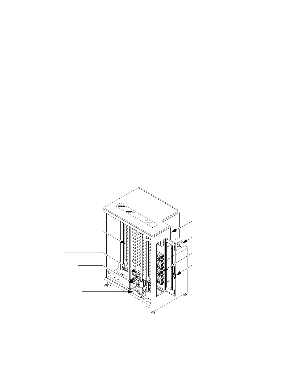
Figure 1 ACL 4/52 Librar
y
Library Description
The ACL 4/52 library (figure 1) is the automated storage and
retrieval component of an automated tape library system. It
accommodates either four DLT 2000, four DLT 4000, or four DLT
7000 tape drives and is capable of storing a maximum of 48 Digital
Linear Tape (DLT) cartridges in a Fixed Storage Array (FSA). An
operator-accessible load port at the front of the library can hold an
additional four tape cartridges for a total of 52. A host computer
communicates with the library through a SCSI interface using the
SCSI-2 medium changer command set. In a typical operation, the
host commands the robotics to transfer tape cartridges between
storage bins (in the FSA), tape drives, and the load port. Each time
a tape cartridge is transferred, a gripping mechanism is moved to
the tape cartridge location wher e it “picks” the tape cartridge, then
moves to and “places” the cartridge in the new location.
1
Fixed Storage Array (FSA)
(48 Cartridge Bins)
Gripper
Vertical Carriage
Horizontal Carriage
(Left Side Cosmetic Panel Removed)
2
(Front)
Load Port
Control Panel
Tape Drives (4)
(DLT 7000 shown)
Front Door
TA00038d
Page 19
Chapter 1 Library Overview
Library Description
ACL 4/52 Library Numbering Conventions
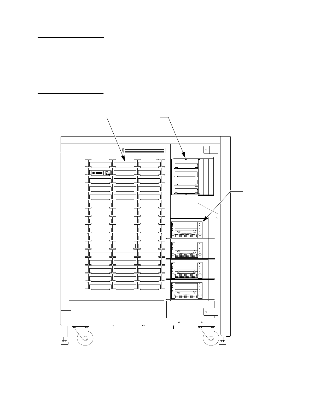
Figure 2 ACL 4/52 Library
Numbering Conventions
FSA Bins
1
Bin 0
Bin 2
Bin 3
Bin 4
Bin 5
Bin 6
Bin 7
Bin 8
Bin 9
Bin 10
Bin 11
Bin 12
Bin 13
Bin 14
Bin 15
Figure 2 is a view from the left si de of the library with the lef t cosmetic
panel removed. Figure 2 depicts the numbering convention for the
library's Fixed Storage Array bins, load port bins, and tape driv es. This
numbering convention is used in the diagnostic software and the
library menu mode, which is viewed in the status display area of the
control panel.
Load Port Bins
Bin 16
6711BA
Bin 17
Bin 18
Bin 19
Bin 20
Bin 21
Bin 22
Bin 23
Bin 24
Bin 25
Bin 26
Bin 27
Bin 28
Bin 29
Bin 30
Bin 31
Bin 32
Bin 33
Bin 34
Bin 35
Bin 36
Bin 37
Bin 38
Bin 39
Bin 40
Bin 41
Bin 42
Bin 43
Bin 44
Bin 45
Bin 46
Bin 47
Bin 0
Bin 1
Bin 2
Bin 3
Drive 0
Drive 1
Drive 2
Drive 3
DLT Tape Drives
(DLT 7000 shown)
TA00053c
ACL 4/52 Operator’s Guide 3
Page 20
Chapter 1 Library Overview
Operator Accessible Components
Control Panel
Operator Accessible Components
1
The operator of the ACL 4/52 library will need access t o the fol lowing:
• Control panel
• Load port
• Front door
• Rear panel
• DLT tape drive status/control panel
Additionally, the control panel allows you to perform several types of
functions (operational and diagnostic) using the menu mode. The
menu mode functions and the items listed above are discussed in the
following paragraphs.
1
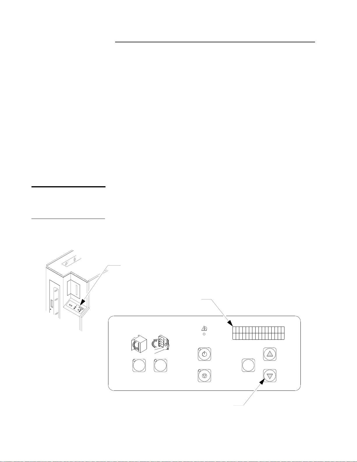
The control panel (figure 3) is located on the right front of the library.
Its features are described in table 2 on page 11.
Figure 3 Control Panel
Control Panel
OPEN CLOSE
Status Display Area
(16 Characters/2 Lines)
FAULT
STANDBY
SELECT
STOP
Scrolling Buttons
(Up
4 ACL 4/52 Operator’s Guide
{
and Down
}
↑
{↓})
TA00003/15
Page 21

Table 1 Control Panel
Functions
Feature Function
Chapter 1 Library Overview
Operator Accessible Components
(load port)
OPEN
(button/
indicator)
(load port)
CLOSE
(button/
indicator)
STANDBY
(button/
indicator)
The (load port)
inserting or removing tape cartridges.
Pressing the
• park the robotics (the green indicator blinks until the robotics are parked)
• unlock and open the load port door (the indicator is steadily lit), and then
• re-lock the load port door in the open position (the indicator is off).
(Once the door is opened, you can insert/remove tape cartridges into/out of the four
bins).
When the load port door is in the open position, the (load port)
used to unlock the door before closing it.
Pressing the
• park the robotics (the green indicator blinks until the robotics are parked), then
• unlock the door (the indicator is steadily lit).
(Once the indicator is steadily lit, you can close the door. The library will lock it in the
closed position.)
You can set the state of the library (on-line or off-line) with this button. With the
library in the on-line mode, pressing this button toggles the library to the off-line state
(green indicator on). While in
control panel menu mode is available and the diagnostic port on the rear panel
DIAG
(
) is active. Pressing the button again toggles the library to the on-line state. The
green indicator functions as follows:
• Off (solid) -
• On (solid) -
• Blinking - Waiting for the current on-line operation to complete.
OPEN
OPEN
CLOSE
STANDBY
STANDBY
button is used to unlock the load port door for the purpose o f
button causes the library to:
button causes the library to:
STANDBY
is not selected. The library is on-line.
is selected. The library is off-line.
, host communications are disabled, the
CLOSE
button is
STOP
(button/
indicator)
You can stop the robotic equipment by pressing the
removes power to the robotic equipment and illuminates the (green) indicator.
Pressing the button again restores the power to the robotics and extinguishes the
indicator.
ACL 4/52 Operator’s Guide 5
STOP
button. When pressed, it
Page 22

Chapter 1 Library Overview
Operator Accessible Components
Feature Function
SELECT
↑
(scroll-up),
and
↓
(scroll-down)
(buttons)
FAULT
(indicator)
Status
Display
Area
Load Port
With the library in the
menu mode. While in the menu mode,
options, shown in the second line of the status display area (SDA), for execution.
The
and ↓ buttons are used in conjunction with the
↑
menu mode, these buttons are used for navigating through the menu options.
(For detailed procedures on using the menu mode, see Chapter 3, Operating
Procedures.)
When illuminated (red), it indicates the library is in an error condition. Observe the
SDA for a specific message. (For a listing and detailed description of all status
messages shown in the SDA, see Chapter 4, Operator Troubleshooting.)
This is a 16-character (5x7 dot-matrix Liquid Crystal Display {LCD}) /2-line display . It
shows status messages that describe the operating state of the library. It is also used
for displaying menu options wh ile the library is in the menu mode.
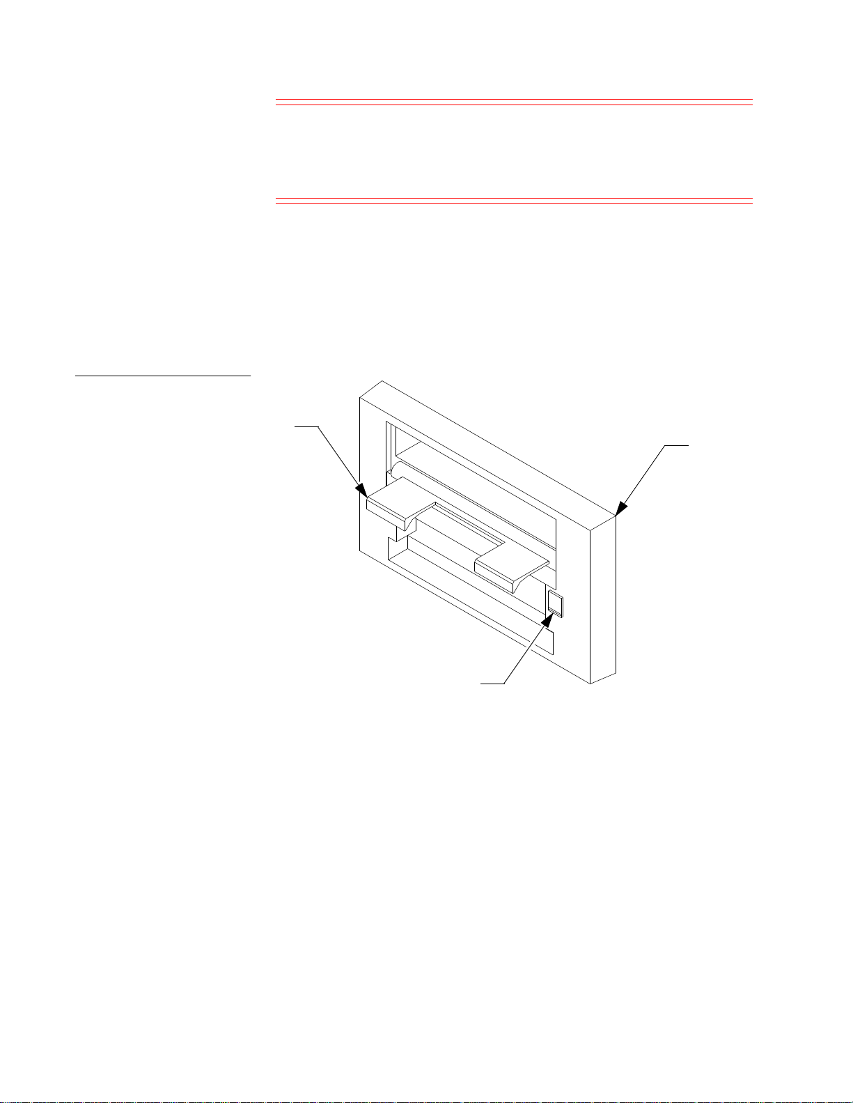
1
The load port (figure 4 on page 7) is located at the front of the library
STANDBY
state, pressing the
SELECT
SELECT
allows you to choose menus and
SELECT
button activates the
button. While in the
above and to the left of the control panel. Under library control and in
conjunction with the load port
OPEN
and
CLOSE
buttons, it allows
the operator to insert and/or remove up to four tape cartridges. (See
table 2 on page 11 for a description of the load port buttons.)
For a load operation, press the load port
OPEN
button. When the
indicator stops blinking, the load port door automatically opens (and
locks in the open position) allowing the operator to insert tape
cartridges.
After the operator presses the
CLOSE
button and closes the door, the
tape cartridge(s) is (are) made available to the library.
Caution:
You must release the
CLOSE
button before pushing the
load port door closed.
For the unload operation, the gripper places tape cartridges in the load
port bins. Looking through the view port, the operator will be able to
decide if an unload operation is necessary. Pressing the
OPEN
button
automatically opens the door allowing the operator to r emove the tape
cartridge(s).
6 ACL 4/52 Operator’s Guide
Page 23

Figure 4 Load Port
Chapter 1 Library Overview
Operator Accessible Components
Load Port (Closed)
(View Port)
TA00015B
Load Port (Open)
Cartridge
Front Door (with Interlock Switch)
(Closes to Left)
The library door is shown in figure 5. This door can be used to access
1
the DLT tape drive status/control panels for manually unloading,
ejecting and removing a tape cartridge from the drives.
For safety purposes, an interlock switch (shown in Figure 4) removes
power from the robotics equipment when the door is opened.
Typically, the front door will be used by FSEs during maintenance
procedures.
ACL 4/52 Operator’s Guide 7
Page 24

Chapter 1 Library Overview
Operator Accessible Components
Warning: To prevent injury from moving components, always press
the control panel
front door. The
STANDBY
STANDBY
button before opening the
indicator will flash until the
current command is completed.
Figure 5 Front Door
Note: When the
displayed, the front door may be opened. Always press the control
panel
STOP
STANDBY
indicator is on solid and
button before opening the front door.
Front Door (Open)
Handle
System Off-line
is
Interlock
Switch
Interlock
Switch
(Open to Right)
Rear Panel
1
The rear panel of the library is shown in figure 6. It contains the AC
power switch, AC power receptacle and the communication ports for
the host, tape drives and diagnostic PC. The operator’s only
responsibility concerning the rear panel is verifying the cables are
properly connected and applying/removing power to/from the
library through the AC power switch.
8 ACL 4/52 Operator’s Guide
Page 25

Figure 6 Rear Panel
Chapter 1 Library Overview
Operator Accessible Components
DIAG
SCSI PORT 4
SCSI PORT 3
* Connectors shown for default
SCSI configuration.
DLT Tape Drive Status/Control Panel
AC Po wer Receptacle
and Switch
Spares
(Breakouts)
A status/control panel is located on each DLT tape drive (figure 7,
1
figure 8, and figure 9). The features of the status/control panel are
described in table 3 on page 12.
SCSI PORT 2
SCSI PORT 1
TA00032
For detailed discussions of the DLT tape drive, refer to the appropriate
product manual.
ACL 4/52 Operator’s Guide 9
Page 26
Chapter 1 Library Overview
Operator Accessible Components
Figure 7 DLT 2000 Tape
Drvie Status/Control Panel
2.6
6.
0
10.
0
Compress
De
O
ns
v
erride
i
ty
De
Sele
ns
i
ty
c
t
Figure 8 DLT 4000 Tape
Drive Stat us/Control Panel
Protec
T
C
le
Ha
a
Use
O
U
W
r
ite
t
ed
pe
i
n
U
se
a
nin
g
T
a
pe
p
e
ra
n
te
dle
n
lo
ad
TA00040a
O
Select
De
v
Densit
erride
2.
6.0
10.0
Compres
ns
i
t
y
Wr
P
i
Tape
Clea
H
ro
t
U
s
e
n
Operate
an
d
Unloa
te
ect
e
d
i
n Use
ing Tape
le
6
s
y
d
TA00040a
10 ACL 4/52 Operator’s Guide
Page 27
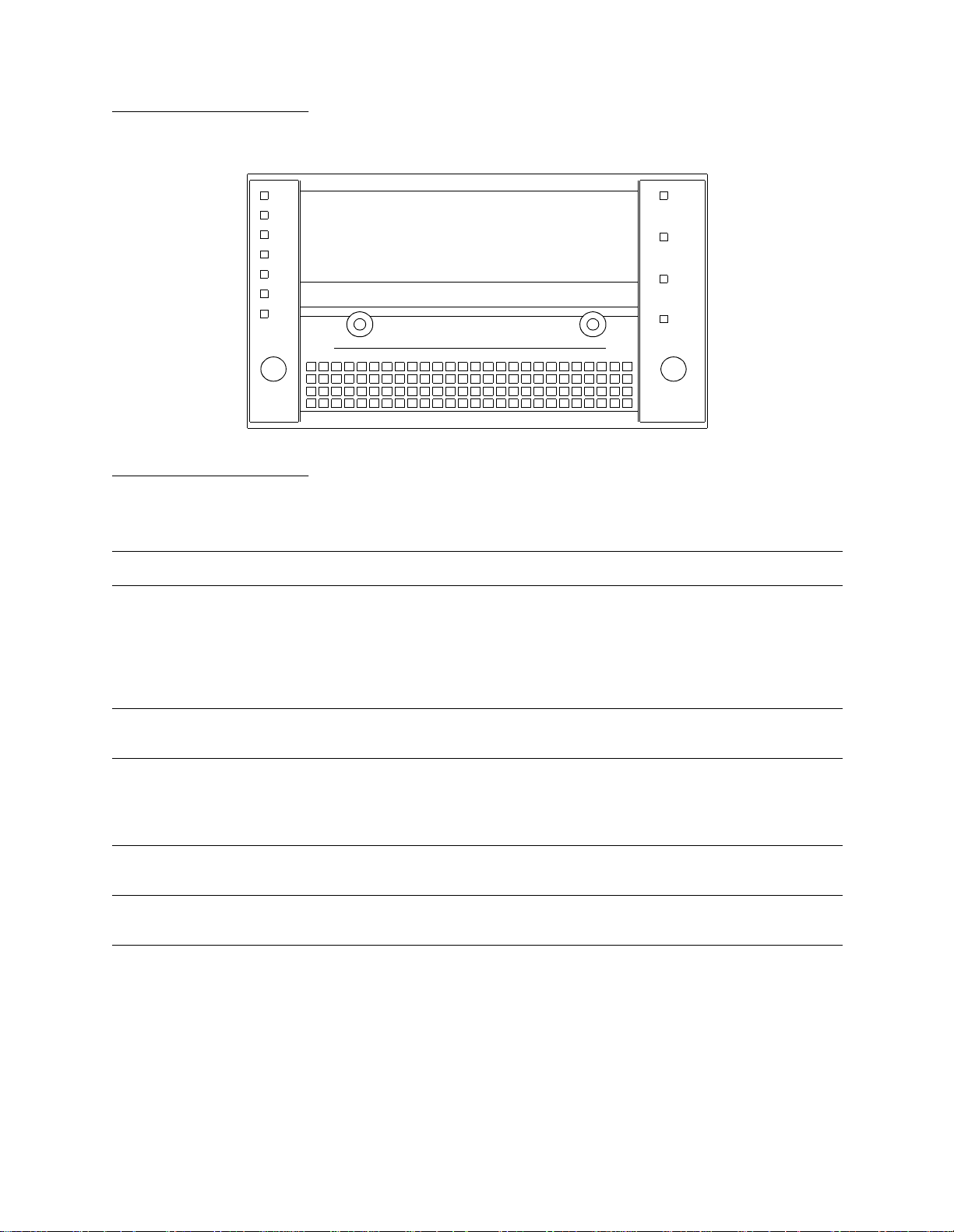
Figure 9 DLT 7000 Tape Drive
Status/Control Panel
Chapter 1 Library Overview
Operator Accessible Components
Table 2 DLT Tape Drive
Status/Control Panel
Functions
Feature Function
Unload
(button)
Sele
2.6
6
10
2
35
Comp
De
O
.0
0.0
.0
/1
5
.0
.0
r
ess
n
sit
ve
y
r
rid
e
c
t
U
nl
Write
Pr
o
te
Tap
e
In
u
se
U
se
Cl
e
an
Ta
p
e
Operate
Handl
o
ad
c
ted
i
ng
e
This button moves all tape from the drive take-up reel to the tape cartridge
supply reel, and ejects the cartridge into position for removal.
Operate Handle
(indicator)
Use Cleaning Tape
(indicator)
Tape in Use
(indicator)
Write Protect
(indicator)
Note The tape cartridge must be completely rewound and unloaded
before ejecting and removing the tape cartridge from the drive.
Depending on tape position, this operation takes 10 to 120 seconds.
This green indicator lights when the insert/release handle is ready to operate.
This yellow indicator lights when the drive hea d needs cleaning or the current
cleaning tape is bad. After unloading the cleaning tape cartridge, the indicator
remains lit if the cleaning operation was not completed or the cleaning tape
cartridge was bad.
This yellow indicator blinks while the tape cartridge loads and calibrates. After
calibration, it remains lit.
This orange indicator lights when the loaded tape cartridge is write-protected.
ACL 4/52 Operator’s Guide 11
Page 28

Chapter 1 Library Overview
Cartridge/Tape Drive Compatibility
Table 3 Cartridge/Tape
Drive Campatibility
Cartridge/Tape Drive Compatibility
The ACL 4/52 library is capable of supporting the DLT 2000, DLT
4000, and DLT 7000 tape drives. The library is also capable of
supporting the CompacTape III and CompacTa pe IV cartridges, which are
dark gray and black, respectively. When loading the library with
cartridges, observe the compatibility of cartridges and tape drives as
defined in table 3.
Cartridge Type
CompacTape III
Cartridge
CompacTape IV
Cartridge
DLT 2000
Tape Drive
Compatible Compatible Compatible
Not
Compatible
Caution: DO NOT USE CompacTape I, CompacTape II, or
CompacTape IIIXT tape cartridges in this library.
DLT 4000
Tape Drive
Compatible Compatible
DLT 7000
Tape Drive
1
12 ACL 4/52 Operator’s Guide
Page 29
Chapter 1 Library Overview
Menu Mode Structure
Menu Mode Structure
Some of the operator’ s responsibilities include using the control panel
menu mode. The menu mode is entered by placing the library in the
standby mode and then pressing the
panel. Once the menu mode is entered, the
DOWN-ARROW (
menu and the
)
buttons are used for navigating through the
↓
SELECT
button allows the operator to choose menus
and/or execute options. When in the menu mode, the Status Display
Area (SDA) displays two lines of the menu:
• The upper line (line #1) of the display is passive. It simply shows
the name of the current menu or sub-menu.
• The lower line (line #2) is the active line. When the operator
presses the
SELECT
button, the sub-menu or function displayed
on the lower line is the option selected or executed.
Line #1
Line #2
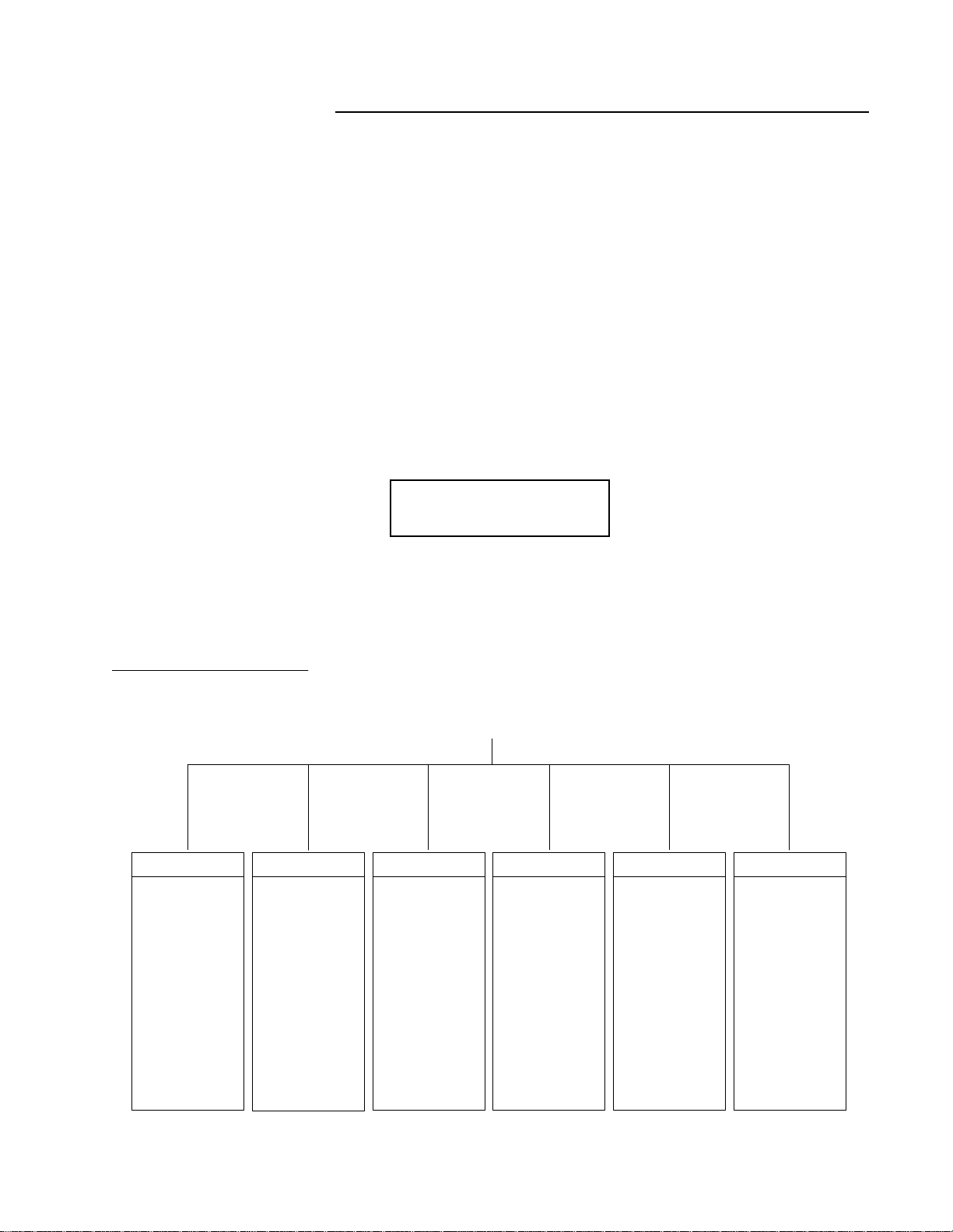
The overall structure and capabilities of the menu mode are shown in
figure 10 on page 13. The functions for which the operator will be
responsible, and a discussion of navigating through the menus is
provided in the paragraphs that follow.
SELECT
UP-ARROW
button on the control
)
and
(
↑
1
Figure 10 Menu Structure
Configuration
Inquiry
SCSI Address
Power-Up State
Num of Drives
Auto Clean
Retries
Auto Load
Language
Set View
Auto Inventory
No Barcode Scan
Emulate Exabyte
Temperature Det
Exit Menu
Unload
Clean
Exit Menu
Drive Control
MAIN MENU
Calibration
Cal All
Cal Storage
Cal Drives
Cal Load Port
Exit Menu
System Test Robot Control Diagnostics
Random Shuffle
Random /No Scan
Pick Each Bin
Pick All
Report Results
Exit Menu
Empty Load Port
Pick Bin
Pick Drive
Place Bin
Place Drive
Barcode Bin
Barcode Drive
Exit Menu
Home All
Selftest All
Status Actuator
Move Actuator
Inventory
Exercise All
Exit Menu
ACL 4/52 Operator’s Guide 13
Page 30

Chapter 1 Library Overview
Menu Navigation
Menu Navigation
After placing the library in the standby mode and pressing the
SELECT
To navigate through the menu, press the
of the desired main menu is displayed on line #2 of the SDA, then
release the
Line #1 changes to the main menu selection and line #2 shows the first
sub-menu. Press the
continue pressing the
displayed. Pressing
first option in line #2. Again, the operator must scroll through the
options list until the desired option is displayed. The operator selects
the option and it is executed.
An
option list. When the operator chooses
previous menu. At that point, another pr ocedure can be performed, or
the operator can scroll to the next
menu mode. The quickest way to exit the menu mode is to press the
SELECT
button on the control panel, the menu mode is activated.
or ↓ buttons until the name
↑
SELECT
Exit
option is provided at the end of each menu, sub-menu and
↑
and
button.
SELECT
↑
SELECT
or
buttons simultaneously.
↓
button for the first sub-menu, or
or
buttons until the sub-menu desired is
↓
chooses the sub-menu and displays the
Exit
, he/she are returned to the
Exit
until completely exiting the
1
Note: After an operation is executed, the results displayed in the SDA must
be cleared befor e the quick method of exiting will be avai lable. To clear
the results of an operation from the SDA, press the
figure 11 on page 15 is an example of menu navigation. It shows the
commands and associated SDA displays involved in changing the
AUTO CLEAN
option from DISABLED (factory default) to ENABLED.
or ↓ button.
↑
14 ACL 4/52 Operator’s Guide
Page 31
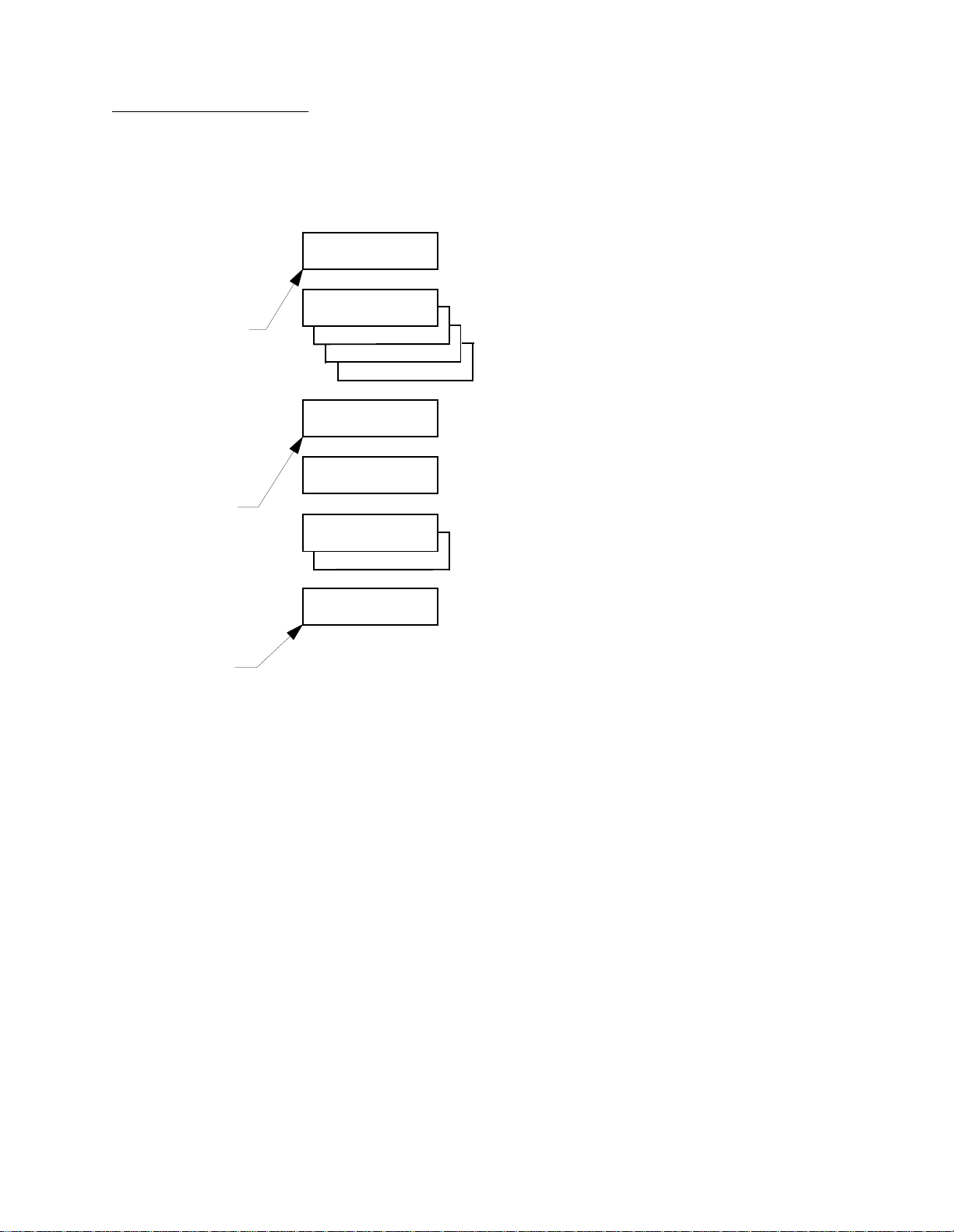
Figure 11 Menu
Navigation example
Chapter 1 Library Overview
Menu Navigation
Status Display Switch Description
Menu:
Configuration
Menu: Configurati
M
a
S
u
Inquiry
SCSI Address
Pow er- Up S ta te
Num of Drives
Menu: Configurati
Auto Clean
Menu: Auto Clean
Enabled
Menu: Enabled
..Workin g
..SUCCESS..
S
-
E
the “Configuration” Men u
Select
L
E
C
-
T
-
the INQUIRY Sub-Menu
-
-
↓
↓
the SCSI ADDRESS Sub-Menu
the PWR-UP STATE Sub-Menu
↓
-
↓
the NUM OF DRIVES Sub-Menu
Bypass
Bypass
Bypass
Bypass
Menu: Auto Clean
Enabled<
-
S
<
(
E
e the A UTO CLEAN Sub-Menu
L
Choos
ACL 4/52 Operator’s Guide 15
Page 32

Chapter 1 Library Overview
Operator Tasks (using the Menu Mode)
Operator Tasks (using the Menu
Configuration Menu Functions
Mode)
As an operator, you may need to use the configuration, drive control
and diagnostics menus.
Configuration
The
1
• Set or change the library’s SCSI address
• Set or change the tape drive SCSI addresses
• Define the state of the library after the power-up sequence has
completed
• Enable or disable the automatic drive cleaning option
• Enable or disable the retry operation option
• Enable or disable the automatic loading feature
• Set or change the language displayed in the SDA
• Adjust the SDA contrast level
menu allows you to:
1
Setting/Changing the Library’s SCSI Address
The SCSI address (0...7) of the library can be set using the
Address/Robotics
Setting/Changing the Tape Drive SCSI Addresses
This function is used to set the SCSI address (0...7 for libraries with
DLT 2000 or DLT 4000 tape drives, and 0...15 for libraries with DLT
7000 tape drives) of each tape drive in the library. This can be done
through the
Defining the Library’s Power-Up State
You have the option of defining the starting co ndi t ion of the library,
either on-line or standby (off-line), after power-up, self-tests and
initialization has occurred. The default is on-line. You can change it by
using the
Enabling/Disabling Automatic Drive Cleaning
The automatic drive cleaning feature has two modes of drive cleaning
support: Host Initiated and Fully Automatic.
Power-Up State
sub-menus.
SCSI Address/ Drive n
sub-menu .
sub-menus.
SCSI
1
1
1
1
16 ACL 4/52 Operator’s Guide
Page 33

Chapter 1 Library Overview
Operator Tasks (using the Menu Mode)
In Host Initiated Cleaning Mode, drive cleaning is enabled by your
System Administrator at the host computer. Although the library unit
will internally track cleaning tape cartridge movement and use, the
library unit provides no cleaning support in this mode. The host is
responsible for all cleaning functions such as detecting when a drive
requires cleaning, tracking and selecting cleaning tape cartridges,
initiating media movement of the cleaning tape cartridge to the drive
and determining when a cleaning tape cartridge has been “used up.”
Drive cleaning in the Fully Automatic Cleaning Mode is also enabled by
your System Administrator at the host computer. However, in this
mode, the library unit monitors each drive’s status to determine when
a drive requires cleaning and initiates action when that determination
is made. In this case, the library unit selects an available cleaning tape
cartridge, handles media movement of the cleaning tape cartridge to
and from the drive and supervises the cleaning operation in the drive.
The library unit tracks cleaning tape cartridges within the library,
monitors cleaning tape cartridge use and determines when a cleaning
tape cartridge has been “used up.” A “used up” cleaning tape
cartridge is exported from the library to the load port under control of
the library.
The library is shipped with automatic drive cleaning disabled. If you
want this feature enabled, you can use the
Enabling/Disabling the Retry Option
Auto Clean
sub-menu.
If a failure occurs during a movement command and this option is
enabled, the library will attempt to recover and retry the operation. If
this option is disabled, no r etries ar e made and the err or is reported the
first time. The default is to have retries enabled. If you want this
feature disabled, you can use the
Setting/Changing the Library’s Language
Retries
sub-menu .
This function allows you to change the language displayed in the SDA.
The default language is English. If you want to change the language,
you can use the
Francais, Deutsch, Espanol
Adjusting the Display Area Contrast
Language
sub-menu. The options are:
Italiano
and
.
English
,
This function allows you to change the contrast of the SDA for easy
viewing at different angles. There are ten different contrast settings to
choose from in this menu. The default setting is five. To change the
contrast, use the
Set View
sub-menu.
1
1
1
Drive Control Menu Functions
You can use the
Drive Control
menu to:
1
ACL 4/52 Operator’s Guide 17
Page 34

Chapter 1 Library Overview
Operator Tasks (using the Menu Mode)
• Unload a tape cartridge from a specific drive
• Clean a specific drive
Unloading a Tape
This feature allows you to unload the tape (preparing to eject and
remove the tape cartridge) in a drive that you specify. To perform this
function, use the
Drive 2, Drive 3,
Unload
where:
sub-menu. The options are:
Drive 0, Drive 1
,
Menu ModePhysical Location
Drive 0
Drive 1
Drive 2
Drive 3
Cleaning a Drive
= Top Drive
= Second Drive
=Third Drive
=Bottom Drive
This feature allows you to direct a cleaning tape cartridge to a tape
drive that you specify. To perform this function, use the
menu. The options are:
Drive 0, Drive 1, Drive 2, Drive 3,
Clean
where:
sub-
Menu ModePhysical Location
Drive 0
Drive 1
Drive 2
Drive 3
= Top Drive
= Second Drive
=Third Drive
=Bottom Drive
1
1
Diagnostics Menu Functions
You can use the
1
Diagnostics
menu to:
• Display the status of the library
• Perform an inventory of the library
Displaying the Library’s Status
There are two options concerning the status of the library. These
options allow you to display the current condition of each sensor and
the buttons in the library (
Status Sensor
four actuators (horizontal, vertical, extension and gripper) in the
library (
the
menus and the
Status Actuator
Status Sensor
↑
). To display this information in the SDA, use
(not currently supported) and
↓
and
buttons to scroll through the returned
information.
18 ACL 4/52 Operator’s Guide
) or display the position of the
Status Actuator
sub-
1
Page 35

Chapter 1 Library Overview
Operator Tasks (using the Menu Mode)
Note:
Note:
Performing an Inventory
This feature simply allows you to perform an inventory of the library.
The inventory information is then written to nonvolatile RAM. To
perform this function, use the
Inventory
sub-menu.
Currently, all other menu options are reserved for FSEs and are not
discussed here. For detailed instructions on using the control panel in
the menu mode, see Chapter 2, “Operating Procedures.”
With a full library, the inventory will take less than three minutes if all
of the cartridges are properly bar code labeled. The actual inventory
time can take longer if the library is not completely full or if any of the
cartridges are not properly labeled. When the library is full of
unlabeled cartridges the inventory will take over twenty-seven
minutes.
1
ACL 4/52 Operator’s Guide 19
Page 36

Chapter 1 Library Overview
Operator Tasks (using the Menu Mode)
20 ACL 4/52 Operator’s Guide
Page 37

Chapter 2
Chapter 2 Operating Procedures
Operating Procedures
This chapter provides procedures for applying/removing power,
inserting/removing tape cartridges through the load port, manually
unloading a cartridge from a tape drive, and performing procedures
for all functions associated with the control panel menu mode.
2
ACL 4/52 Operator’s Guide
21
Page 38

Operating Procedures
This section contains procedures for executing the following
operator tasks:
• Applying and removing power
• Placing the library on-line or taking it off-line
• Inserting and removing tape cartridges using the load port
• Manually unloading a tape cartridge from a DLT tape drive
2
Applying Power to the Library
Placing the Library On-Line
To apply power to the library:
2
Note:
2
1 Verify the following:
a Front door and load port closed
b All outer skins attached
c All rear panel connections secured
2 At the rear panel, set the AC power switch to the | (on)
position.
3 After several seconds, verify that SDA shows
System On-line
configured for
the SDA. (See Chapter 3, “Operator Troubleshooting,”)
To place the library on-line:
1 With the library power applied and the SDA showing
Off-line
2 Verify that
is only displayed if the library power-up state is
On-line
, press the control panel
System On-line
. Otherwise,
is displayed in the SDA.
System Off-line
STANDBY
System On-line
is displayed in
button.
System
.
Taking the Library Off-Line
22
To take the library off-line:
2
1 With the library power applied and the SDA showing
On-line
2 Verify that
, press the control panel
System Off-line
STANDBY
is displayed in the SDA.
button.
System
Page 39

Chapter 2 Operating Procedures
Operating Procedures
Removing Power from the Library
Inserting Tape Cartridges
To remove power from the library:
2
1 Press the control panel
2 Press the control panel
Off-line
is displayed in the SDA.
STOP
button.
STANDBY
button and verify that
System
3 At the rear panel, set the AC power switch to the O (off) position.
To insert a tape cartridge:
2
Caution:
DO NOT USE CompacTape I, CompacTape II
or CompacTape
IIIXT tape cartridges in this library.
Caution:
Examine all cartridges before loading them into the library
or tape drive. Look for label stock or other foreign material
that may be clinging to the cartridges.
1 Press the load port
OPEN
button and verify the indicator begins
blinking. (It may require several seconds for the load port door to
automatically open.)
Warning:
Mechanical hazards could be exposed when the load port is
partially open or closed. Do not attempt to insert hands or
fingers into the load port opening at any time.
2 With the load port door open, place the tape cartridge(s) in any
available bin. (The pr oper orientation for tape cartridg e insertion is
shown in figure 12 on page 24).
3 Press the load port
Caution:
The load port door is locked in the open position. You must
press the
CLOSE
CLOSE
button.
button before attempting to close the l oad
port door.
4When the
CLOSE
indicator is steadily lit, push the load port door
closed. (The library will lock the door.)
ACL 4/52 Operator’s Guide 23
Page 40
Chapter 2 Operating Procedures
Operating Procedures
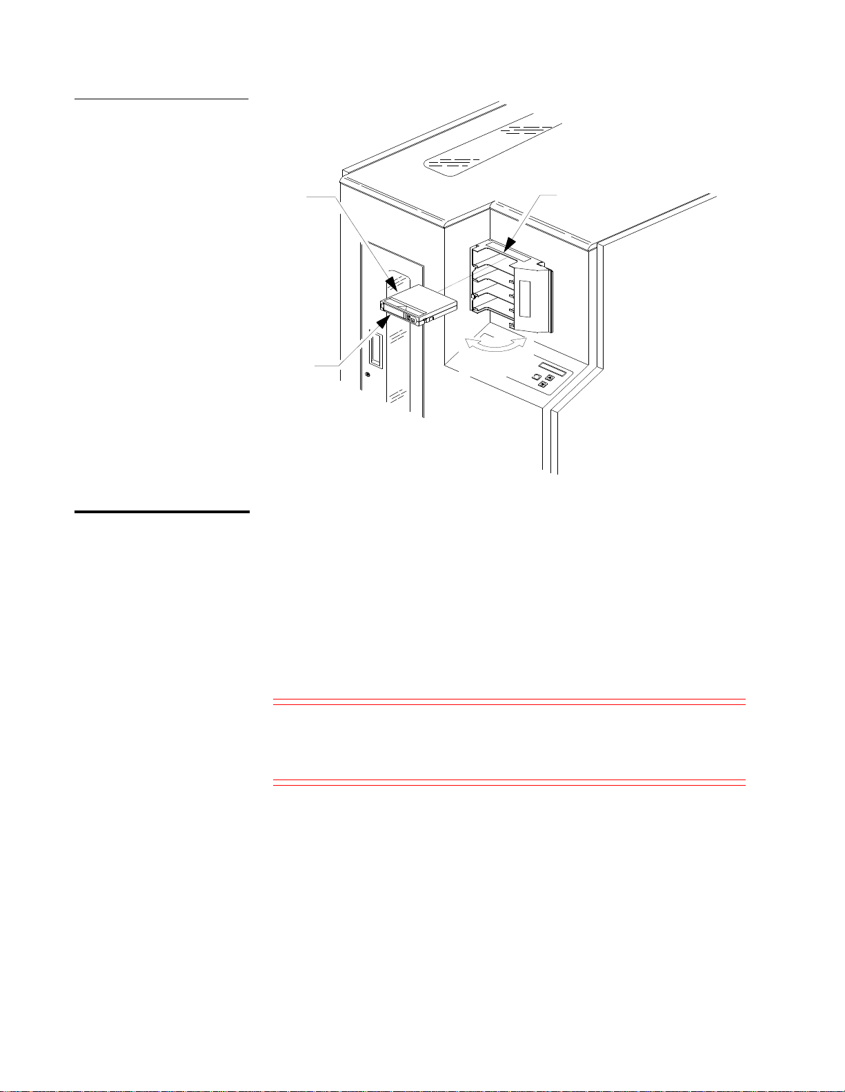
Figure 12 Inserting/Removing
Tapes
Removing Tape Cartridges
Tape Cartridge
Bar code Label
To remove a tape cartridge:
2
Note:
Use the view port to determine whether or not the load port contains
tape cartridges to be removed.
Opens to Right/
Closes to Left
Load Port
TA30010d
1 When tape cartridges are ready to be removed, press the load port
OPEN
button and verify the indicator begins blinking. (It may
require several seconds for the load port door to automatically
open.)
Warning:
Mechanical hazards could be exposed when the load port is
partially open or closed. Do not attempt to insert hands or
fingers into the load port opening at any time.
2 Remove the tape cartridge(s) from the load port bin(s).
3 Press the load port
CLOSE
button.
24 ACL 4/52 Operator’s Guide
Page 41

Chapter 2 Operating Procedures
Operating Procedures
Caution: The load port door is locked when in the open position. You
must press the
CLOSE
button before attempting to close
the load port door.
Manually Unloading the DLT Tape Drive
4When the
CLOSE
indicator is steadily lit, push the load port door
closed. (The library will lock the door.)
To manually unload a DLT tape drive:
2
1 Press the control panel
Off-line
is displayed in the SDA.
2 Press the control panel
STANDBY
STOP
button.
button and verify that
System
Warning: To prevent injury from moving components, always press
the control panel
STOP
button before opening the front
door.
3 Open the front door by pulling the door towards you. (The door
opens to your right.)
Warning: The front door is the only location for manually removing
tape cartridges from the interior of the tape library.
4 On the drive to be unloaded, press the
figure 14) and verify the
on page 9 & figure 8 on page 10).
Note: When you press
Depending on the tape cartridge position, it will ta ke 10 to 120 seconds
before the Operator Handle indicator lights.
5With the
Operator Handle
handle to eject the DLT tape cartridge.
6 Pause for two seconds, then grasp the tape cartridge and slowly
pull it one-half way out of the drive mouth.
ACL 4/52 Operator’s Guide 25
Unload
Unload
Operator Handle
button (figure 13 or
indicator is lit (figure 6
, the tape cartridge will completely rewind.
indicator lit, raise the insert/release
Page 42
Chapter 2 Operating Procedures
Operating Procedures
Caution: If the tape cartridge leader failed to detach f rom the take-up
leader, push the tape cartridge all of the way back into the
drive mouth, press down the insert/release handle, and
return to step #4. Otherwise, continue to step #7.
7 Pull the tape cartridge completely out of the drive.
8 Close the library door.
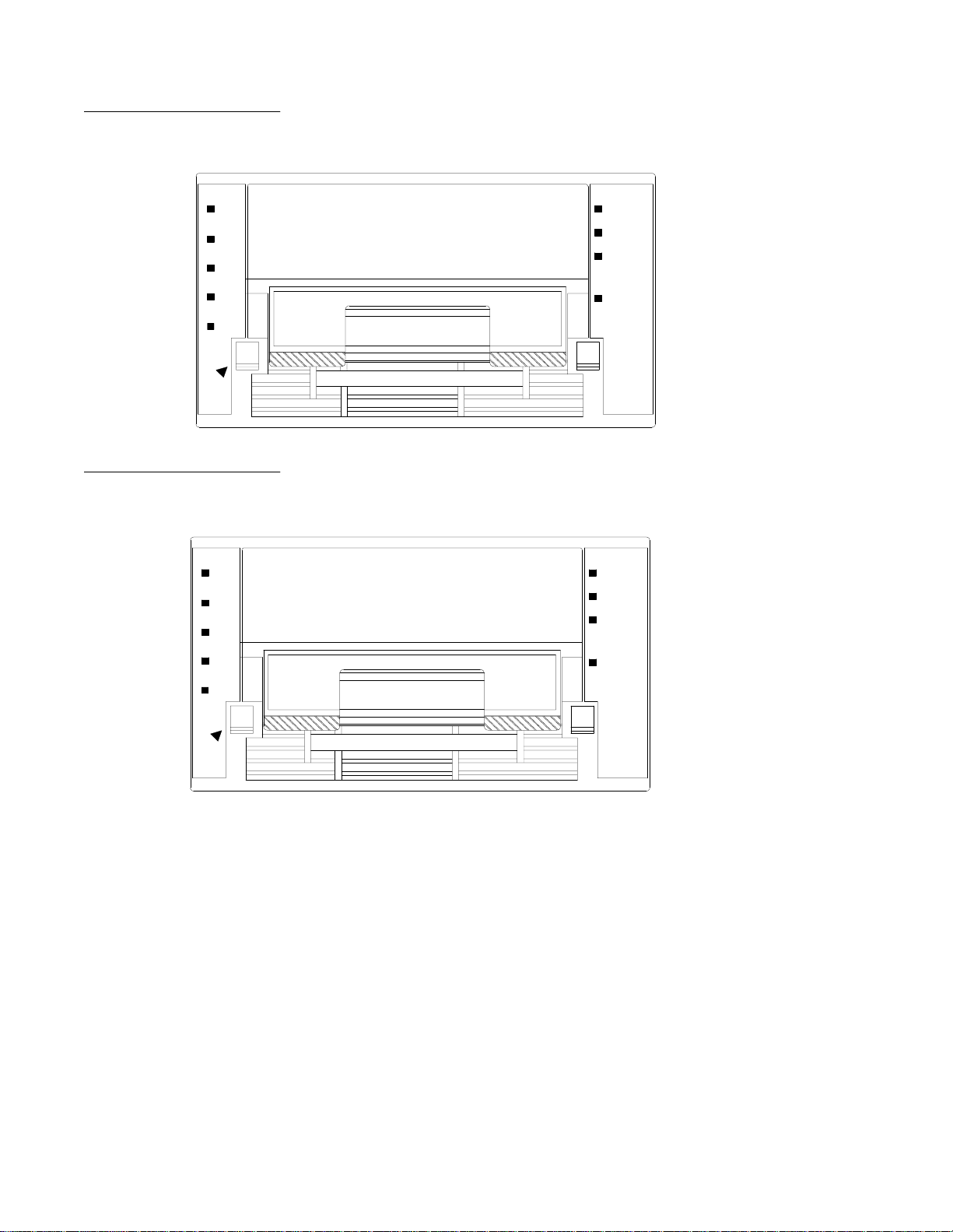
Figure 13 DLT 2000 and
DLT 4000 Manual Unload
10 Press the control panel
Insert/Release
Handle
(Shown in Up
Position)
9 Press the control panel
On-line
is displayed in the SDA.
Unload Button
STOP
button.
STANDBY
button and verify that
System
DLT2000
DLT4000
Front Bezel
TA00056a
26 ACL 4/52 Operator’s Guide
Page 43
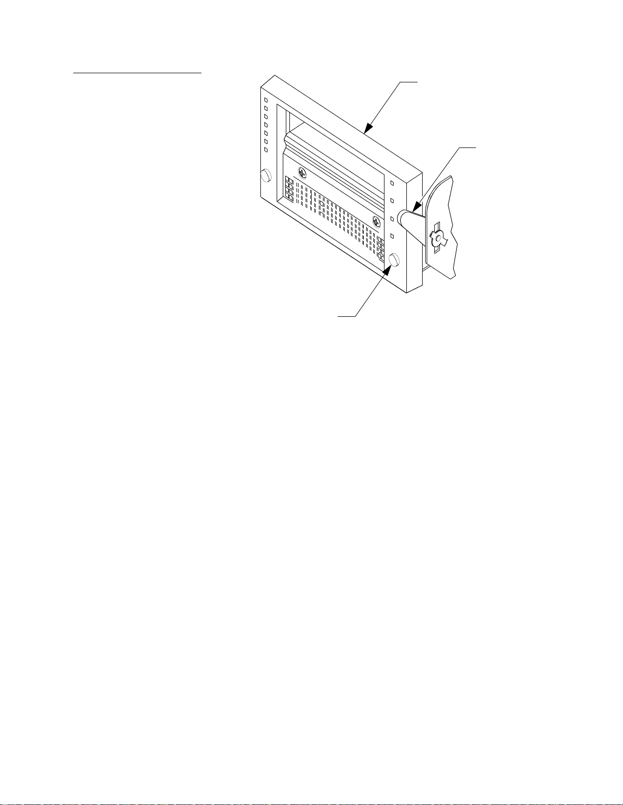
Figure 14 DLT 7000
Unload Button
Insert/Release
Handle
(Shown in Up Position)
TA00056b
DLT 7000
Front Bezel
Manual Unload
Chapter 2 Operating Procedures
Operating Procedures
ACL 4/52 Operator’s Guide 27
Page 44

Chapter 2 Operating Procedures
Turning the Interior Light On/Off
Turning the Interior Light On/Off
Note: The Interior light bulb is not operator replaceable. Notify your Field
Service Engineer to replace the bulb.
The library is normally shipped with the interior light set to the “On”
position. Use the following procedur e to t urn the interior light “On” or
“Off .”
1 Press the control panel
Off-line”
2 Press the control panel
Warning: To prevent injury from moving components, always press
3 Using a 5/32” hex wrench, unlatch the front door.
4 Open the library front door.
is displayed in the SDA.
the control panel
door.
STANDBY
STOP
button.
STOP
button before opening the front
button and verify that “
System
2
Note: The front door is the only access for manually turning the inte rior light
On or Off.
5 Reach through the front door and set the light switch (located on
the far side of the light) to the desired position.
6 Close and latch the library front door.
7 Press (to release) the control panel
8 Press (to release) the control panel
that the library completes the initialization sequence, and
On-line”
is displayed in the SDA.
STOP
button.
STANDBY
button and verify
“System
28 ACL 4/52 Operator’s Guide
Page 45

Chapter 2 Operating Procedures
Turning the Inte rior Lig ht On/ Off
Figure 15 Turning the
Interior Light On/Off
Power Switch
(Shown in Off Position)
Interior Light
Front Door
(Opens to Right)
TA00038d
ACL 4/52 Operator’s Guide 29
Page 46

Chapter 2 Operating Procedures
Operating Procedures Usi ng the Me nu Mod e
Operating Procedures Usin g the Menu Mode
This section contains procedures for entering and exiting the control
panel menu mode and instructions for executing the operator tasks
listed below:
• Setting or changing the library or tape drive SCSI addresses
• Defining the state of the library after the power-up sequence has
completed
• Enabling or disabling the automatic drive cleaning option
• Enabling or disabling the retry operation option
• Setting or changing the language displayed in the SDA
• Adjusting the SDA contrast level
• Unloading a tape cartridge from a specific drive
• Directing cleaning tape cartridges to specific drives for cleaning
• Performing the initial loading of the library
• Displaying the status of the library
2
Entering the Menu Mode
Exiting the Menu Mode
• Performing an inventory of the library
To enter the menu mode:
2
1 Press the control panel
shows
2 Press the
3 Verify the following is displayed in the SDA:
2
There are two different ways to exit from menu mode.
The fast method:
1 From anywhere in the menu, press the
buttons, simultaneously and verify that
displayed in the SDA.
System Off-line
SELECT
Menu:
Configuration
STANDBY
.
button to enter the menu mode.
button and verify the SDA
SELECT
System Off-line
and
↑ or ↓
is
30 ACL 4/52 Operator’s Guide
Page 47

Chapter 2 Operating Procedures
Operating Procedures Using the Menu Mode
Note: After an operation is executed, the results displayed in the SDA, must
be cleared befor e the quick method of exiting will be avai lable. To clear
the results of an operation from the SDA, press the
or ↓ button.
↑
Or the conventional method:
Setting/Changing the Library SCSI Address
1 Use the
SELECT
the
↓
↑
and
buttons to navigate to an
button. (This method will take you one-level up in the
Exit
option, then press
menu each time that you perform it.)
2 Continue to perform step #1 until the following is displayed in the
SDA.
Menu:
Exit
3 Press
SELECT
one final time to exit the menu mode.
To set or change the library SCSI address:
2
1 Enter the menu mode.
2 Press the
SELECT
button to choose the
Configuration
menu and
verify the following is displayed in the SDA:
Menu: Configurati
Inquiry
3 Press the
↓
button one (1) time to bypass the
Inquiry
menu and
verify the following is displayed in the SDA:
Menu: Configurati
SCSI Address
4 Press the
SELECT
button to choose the
SCSI Address
and verify the following is displayed in the SDAl:
Menu: SCSI Addres
Robotics
5 Press the
SELECT
button to choose the
Robotics
verify the following is displayed in the SDA:
Menu: Robotics
SCSI ID 0
6 Use the
library (
and
↑
SCSI ID 0, SCSI ID 1...SCSI ID 7
7 With the proper
SELECT
button.
buttons to navigate to the SCSI ID number for the
↓
).
SCSI ID
number displayed on line #2, press the
8 Exit the menu mode.
sub-menu
sub-menu and
ACL 4/52 Operator’s Guide 31
Page 48

Chapter 2 Operating Procedures
Operating Procedures Usi ng the Me nu Mod e
Note: After changing the SCSI address of the library, one of two things must
happen to set the new SCSI ID. The host controller must issue a “SCSI
Bus Reset,” or the library must be powered off and on again.
Setting/Changing a Tape Drive SCSI Address
To set or change a tape drive SCSI address:
2
1 Enter the menu mode.
2 Press the
SELECT
button to choose the
verify the following is displayed in the SDA:
Menu: Configurati
Inquiry
3 Use the
↓
button to bypass the
following is displayed in the SDA:
Menu: Configurati
SCSI Address
4 Press the
SELECT
button again to choose
the following is displayed in the SDA:
Menu: SCSI Addres
Robotics
5 Use the
↓
button to bypass the
following is displayed in the SDA:
Inquiry
Robotics
Configuration
menu and
menu and verify the
SCSI Address
and verify
sub-menu and verify the
Menu: SCSI Addres
Drive 0
6 Use the
↑
and
↓
buttons to navigate to the proper drive number
(Drive 0, Drive 1, Drive 2, Drive 3), where:
Menu Mode Physical Location
Drive 0
Drive 1
Drive 2
Drive 3
= Top Drive
= Second Drive
=Third Drive
=Bottom Drive
7 With the proper drive number displayed on line #2, press the
SELECT
button and verify the following is displayed in the SDA:
Menu: Drive 0
SCSI ID 0
8 Use the
↑
and
buttons to navigate to the SCSI ID number for the
↓
selected drive (0...7 for libraries with DLT 2000 or DLT 4000 tape
drives and 0...15 for libraries with DLT 7000 tape drives).
32 ACL 4/52 Operator’s Guide
Page 49

Chapter 2 Operating Procedures
Operating Procedures Using the Menu Mode
9 With the proper SCSI ID number displayed on line #2, press the
10
SELECT
Exit
button.
the menu mode.
Note: After changing the SCSI address of the drives, one of three
things must happen to set the new SCSI ID. The Reset Drives
command must be performed from the Diagnostic Software
Package, the host controller must issue a “SCSI Bus Reset,” or
the library must be powered off and on again.
Defining the Library Power-Up State
To define the library power-up state:
2
1 Enter the menu mode.
2 Press the
SELECT
button to choose the
Configuration
menu and
verify the following is displayed in the SDA:
Menu: Configurati
Inquiry
3 Use the
↓
button to bypass the
Inquiry
menu and verify the
following is displayed in the SDA:
Menu: Configurati
Power-Up State
4 Press the
SELECT
button to choose the
Power-Up State
menu and
verify the following is displayed in the SDA:
Menu: Power-Up St
On-line<
Note:
System On-line
is the default. If you want to change t he powerup state to standby, proceed to step 6. Otherwise, exit the menu
mode.
5 Use the
↓
button to bypass the
System On-line
option and verify
the following is displayed in the SDA:
Menu: Power-Up St
Standby
6 With the desired option displayed on line #2, press the
button.
7 Exit the menu mode.
ACL 4/52 Operator’s Guide 33
SELECT
Page 50

Chapter 2 Operating Procedures
Operating Procedures Usi ng the Me nu Mod e
Enabling/Disabling the Auto Clean Option
2
Note:
To enable or disable the auto clean option:
1 Enter the menu mode.
2 Press the
SELECT
button to choose the
Configuration
menu and
verify the following is displayed in the SDA:
Menu: Configurati
Inquiry
3 Use the
Up State
↓
button to bypass the
menus and verify the following is displayed in the SDA:
Inquiry, SCSI Address
and
Menu: Configurati
Auto Clean
4With
Auto Clean
SELECT
displayed on line #2 of the SDA, press the
button and verify the following is displayed in the SDA:
Menu: Auto Clean
Enabled
Auto Clean Disabled
is the default. If you want to enable the automatic
cleaning, proceed to step 6. Otherwise, exit the menu mode.
Power-
Enabling/Disabling the Retry Option
5 With the desired option displayed on line #2, press the
SELECT
button.
6 Exit the menu mode.
To enable or disable the retry option:
2
1 Enter the menu mode.
2 Press the
SELECT
button to choose the
Configuration
menu.
3 Verify the following is displayed in the SDA:
Menu: Configurati
Inquiry
4 Use the
State
and the
↓
button to bypass the
Auto Clean
Inquiry, SCSI Address, Power-Up
menus and verify the following is
displayed in the SDA:
Menu: Configurati
Retries
34 ACL 4/52 Operator’s Guide
Page 51

Chapter 2 Operating Procedures
Operating Procedures Using the Menu Mode
Enabling/Disabling the Auto Load Feature
Note:
2
5With
Retries
displayed on line #2 of the SDA, press the
button and verify the following is displayed in the SDA:
Menu: Retries
Enabled<
Retries Enabled
is the default. If you want to disable this feature,
proceed to step 6. Otherwise, exit the menu mode.
6 Use the
↓
button to bypass the
Enabled
option and verify the
following is displayed in the SDA:
Menu: Retries
Disabled
7 With the desired option displayed on line #2, press the
button.
8 Exit the menu mode.
To enable or disable the auto load feature:
1 Enter the menu mode.
SELECT
SELECT
Note:
2 Press the
SELECT
button to choose the
Configuration
3 Verify the following is displayed in the SDA:
Menu: Configurati
Inquiry
4 Use the
State
, Number of Drives,
↓
button to bypass the
Inquiry, SCSI Address, Power-Up
Auto Clean,
and
Retries
verify the following is displayed in the SDA:
Menu: Configurati
Auto Load
5With
Auto Load
displayed on line #2 of the SDA, pr ess the
button and verify the following is displayed in the SDA:
Menu: Auto Load
Disabled<
Auto Load Disabled
is the default. If you want to enable this feature,
proceed to step 6. Otherwise, exit the menu mode.
menu.
menus and
SELECT
ACL 4/52 Operator’s Guide 35
Page 52

Chapter 2 Operating Procedures
Operating Procedures Usi ng the Me nu Mod e
Setting/Changing the Status Display Area Language
6 Use the
↓
button to bypass the
Enabled
option and verify the
following is displayed in the SDA:
Menu: Auto Load
Enabled
7 With the desired option displayed on line #2, press the
button.
8 Exit the menu mode.
To set or change the status display area language:
1 Enter the menu mode.
2
2 Press the
SELECT
button to choose the
Configuration
3 Verify the following is displayed in the SDA:
Menu: Configurati
Inquiry
4 Use the
↓
button to bypass the
State, Auto Clean, Retries
Inquiry, SCSI Address, Power-Up
Auto Load
and
sub-menus and verify the
following is displayed in the SDA:
SELECT
menu.
Menu: Configurati
Language
Note:
With
SELECT
button and verify the following is displayed in the
displayed on line #2 of the SDA, press the
Language
SDA:
Menu: Language
English<
Note:
English
is the default. If you want to change the language,
proceed to step 6. Otherwise, exit the menu mode.
5 Use the
↑
and
↓
buttons to navigate to the desired language.
English
Francais
Deutsch
Espanol
Italiano
6 With the desired language displayed on line #2, press the
button.
SELECT
7 Exit the menu mode.
36 ACL 4/52 Operator’s Guide
Page 53

Chapter 2 Operating Procedures
Operating Procedures Using the Menu Mode
Adjusting the Display Area Contrast
2
Note:
To adjust the display area contrast:
1 Enter the menu mode.
2 Press the
SELECT
button to choose the
Configuration
menu.
3 Verify the following is displayed in the SDA:
Menu: Configurati
Inquiry
4 Use the
↓
button to bypass the
State, Auto Clean, Retries, Auto Load
Inquiry, SCSI Address, Power-Up
Language
and
sub-menus
and verify the following is displayed in the SDA:
Menu: Configurati
Set View
5With
Set View
displayed on line #2 of the SDA, press the
button and verify the following is displayed in the SDA:
Menu: Set View
Contrast 9
Contrast 5
is the default contrast setting. If you want to change the
contrast, proceed to step 6. Otherwise, exit the menu mode.
SELECT
Unloading a Drive
6 Use the
↑
and
↓
buttons to navigate to the desired contrast.
Contrast 9
Contrast 8
Contrast 7
Contrast 6
Contrast 5<
Contrast 4
Contrast 3
Contrast 2
Contrast 1
Exit
7 With the desired contrast displayed on line #2, press the
SELECT
button.
8 Exit the menu mode.
2
To unload a drive:
1 Enter the menu mode.
ACL 4/52 Operator’s Guide 37
Page 54

Chapter 2 Operating Procedures
Operating Procedures Usi ng the Me nu Mod e
2 Use the
↓
button to bypass the
Configuration
menu and verify the
following is displayed in the SDA:
Menu:
Drive Control
3 Press the
SELECT
button to choose the
Drive Control
menu.
4 Verify the following is displayed in the SDA:
Menu: Drive Contr
Unload
5 Press the
SELECT
button to choose the
Unload
sub-menu and
verify the following is displayed in the SDA:
Menu: Unload
Drive 1
6 Use the
Drive 0
Drive 1
Drive 2
Drive 3
↑
↓
and
buttons to navigate to the proper drive number.
= Top Drive
= Second Drive
=Third Drive
=Bottom Drive
7 With the proper drive number displayed on line #2, press the
SELECT
button and verify the following is displayed in the SDA:
Cleaning a Drive
Menu: Drive n
..Working..
Where “n” = the number of the drive that you selected.
8 When the following is displayed in the SDA, exit the menu mode.
Menu: Unload
Drive n
2
To clean a drive:
1 Enter the menu mode.
2 Use the
↓
button to bypass the
Configuration
menu and verify the
following is displayed in the SDA:
Menu:
Drive Control
3 Press the
SELECT
button to choose the
Drive Control
menu.
38 ACL 4/52 Operator’s Guide
Page 55

Chapter 2 Operating Procedures
Operating Procedures Using the Menu Mode
4 Verify the following is displayed in the SDA:
Menu: Drive Contr
Unload
5 Use the
↓
button to bypass the
Unload
sub-menu and verify the
following is displayed in the SDA:
Menu: Drive Contr
Clean
6 Press the
SELECT
button to choose the
Clean
sub-menu and verify
the following is displayed in the SDA:
Menu: Clean
Drive 1
7 Use the
Drive 0
Drive 1
Drive 2
Drive 3
↑
= Top Drive
= Second Drive
=Third Drive
=Bottom Drive
and
↓
buttons to navigate to the proper drive number.
8 With the proper drive number displayed on line #2, press the
SELECT
button and verify the following is displayed:
Menu: Drive n
..Working..
Displaying the Library’s Actuator or Sensor Status
Where “n” = the number of the drive that you selected.
9 When the following is displayed in the SDA, exit the menu mode.
Menu: Clean
Drive n
To display the library’s actuator or sensor status:
2
1 Enter the menu mode.
2 Use the
↓
button to bypass the
Calibration, System Test
Configuration, Drive Control
Robot Control
and
,
menus and verify the
following is displayed in the SDA:
Menu:
Diagnostics
ACL 4/52 Operator’s Guide 39
Page 56

Chapter 2 Operating Procedures
Operating Procedures Usi ng the Me nu Mod e
3 Press the
verify the following is displayed in the SDA:
4 Press the
Selftest All
the SDA:
5 Use the
display (
Note:
6 With the selection displayed on line #2, press the
7 Use the
displays to review the information returned.
Examples are shown below.
SELECT
Menu: Diagnostics
Home All
↓
button two (2) times to bypass the
sub-menus. Then verify the following is displayed in
Menu: Diagnostics
Status Actuator
↑
and
Status Actuator
Status Sensor
↑
and
button to choose the
↓
buttons to scroll to the function that you want to
or
is not currently supported.
↓
buttons to scroll through the (SDA line #2)
Status Sensor
Diagnostics
).
menu and
Home All
SELECT
and
button.
Performing an Inventory
Status Actuator
Menu: Status Actu
1.51 11.8 3.25 C
1.51
11.8
3.25
C
8 When you have finished viewing the status of the library sensors
or actuators, exit the menu mode.
2
To perform an inventory:
1 Enter the menu mode.
2 Use the
Calibration, System Test
following is displayed in the SDA:
= Horizontal position
= Vertical position
= Extension position
= Gripper state (Closed, Open and Unknown)
↓
Menu:
Diagnostics
Example
button to bypass the
Robot Control
and
Configuration, Drive Control
menus and verify the
,
40 ACL 4/52 Operator’s Guide
Page 57

Chapter 2 Operating Procedures
Operating Procedures Using the Menu Mode
3 Press the
SELECT
button to choose the
Diagnostics
menu and
verify the following is displayed in the SDA:
Menu: Diagnostics
Home All
4 Press the
↓
button five (5) times to bypass the
All, Status Actuator, Status Sensor
Move Actuator
and
Home All, Selftest
sub-menu s.
Then verify the following is displayed in the SDA:
Menu: Diagnostics
Inventory
5With
Inventory
displayed on line #2, press the
SELECT
button.
Note: With a full library, the inventory will take less than three
minutes if all of the cartridges are properly bar code labeled.
The actual inventory time can take longer if the library is not
completely full or if any of the cartridges are not properly
labeled. When the lib rary is full of unlabeled cartridges the
inventory will take over twenty-seven minutes.
6 When the SDA returns to the previous menu as shown below (i.e.,
inventory is complete), exit the menu mode.
Menu: Inventory
Success
ACL 4/52 Operator’s Guide 41
Page 58

Chapter 2 Operating Procedures
Operating Procedures Usi ng the Me nu Mod e
42 ACL 4/52 Operator’s Guide
Page 59

Chapter 3
Chapter 3 Operator Troubleshooting
Operator Troubleshooting
This chapter provides explanations of status messages displayed in
the Control Panel Status Display Area (SDA) as well as the associated
action necessary (if any) to rectify specific problems.
3
ACL 4/52 Operator’s Guide
43
Page 60

Table 4 Status Messages
Status Message Description/Action
System On-line.
System Off-line.
Operator Troubleshooting
Table 4 is a listing of all status messages displayed in the SDA.
Column #1, “Status Message,” shows the two lines of the SDA. (If
there is only one line of text in the message, it is displayed on line
#1.) The “Description/Action” column provides a brief
explanation of the message and, where necessary, steps that you
can take to resolve any problem associated with the message.
The library is on-line and ready to communicate with the host
computer.
The library is off-line and ready to accept commands from the
diagnostic PC (
DIAG
port) or enter the control panel menu mode.
3
The library is transitioning from off-line to on-line but must complete a
Going On-line...
command that is (currently) executing. When finished,
line
is displayed in the SDA.
Please Wait.
The library is transitioning from on-line to off-line but must complete a
Going Off-line...
command that is (currently) executing. When finished,
line
is displayed in the SDA.
Please Wait.
This is the first message displayed in the SDA when the library power
System Power-Up.
Initializing...
Wait for On-line.
44 ACL 4/52 Operator’s Guide
is cycled from off to on.
This is the second message displayed in the SDA, after
Power-Up
library successfully completes init ialization,
displayed.)
, when the library power is cycled fr om o ff to on. (When the
System On-
System Off-
System
System On-line
is
Page 61

Status Message Description/Action
In the event of an initialization failure (library power has been cycled
On-line Init Fail
from off to on), this message is displayed in the SDA following the
Initializing...Wait f or On-line
completes initialization,
message. (When the library successfully
System On-line
Chapter 3 Operator Troubleshooting
Operator Troubleshooting
is displayed in the SDA.)
System Stopped
System DoorOpen
The control panel
The library front door is open.
STOP
button was pressed.
ACL 4/52 Operator’s Guide 45
Page 62

Chapter 3 Operator Troubleshooting
Other Problems
Table 5 Other Problems
Problem Resolution
A tape drive is not
ejecting the
cartridges properly.
One or more cables
are disconnected
from the rear panel.
Other Problems
In addition to the status messages described in the previous section,
there are other problems that may occur. Table 5 lists two of these
problems and the steps to take to resolve them.
Note: Coordinate your efforts with the System Administrator.
1) Use the procedure “Unloading a Tape” on page 18 to remove the cartridge.
2) If the problem persists, notify your FSE.
1) Perform the procedure “Defining the Library’s Power-Up State” on page 16.
2) Reconnect the cables referencing figure 6 on page 9.
3) Perform the procedure “Applying Power to the Library” on page 22.
3
Note: For any other problem not listed, notify your FSEs.
46 ACL 4/52 Operator’s Guide
Page 63

Glossary
Glossary
A
B
C
actuators
library to manipulate cartridges. These include the gripper,
extension axis, vertical and horizontal axes.
automated tape library
system for DLT tape cartridges.
bar code label
cartridges.
bar code scanner
extension axis that reads the cartridge bar code labels.
calibration
configuration required for successful operation of the
library.
CHM
control panel
contains the status display area, as well as indicato rs and
control buttons.
Robotic components that move inside the
A robotic storage and retrieval
The identification label on DLT tape
A device that is mounted on the
The software measurements and
Cartridge handling mechanism
The panel on the front of the library that
D
E
DLT
Digital linear tape
EIA/TIA-574
protocol standard for nine pin connectors, sometimes
referred to as RS-232. The diagnostic port (
rear of the library, uses this protocol.
A serial communications cabling and
DIAG
), on the
47ACL 4/52 Operator’s Guide
Page 64

Glossary
extension axis assembly Mounted onto the vertical axis,
the extension axis assembly consists of the gripper
assembly and the horizontal axis on which the gripper
assembly is mounted.
extension axis belt The drive belt connecting the
extension motor/gearbox to the gripper.
F
G
H
L
FCC Class A Standard established by the U.S. Federal
Communications Commission governing electromagnetic
emissions.
FSA Fixed storage array. This is a 3-column by 16-row
fixture mounted inside the library. Its purpose is to store up
to 48 cartridges in the library.
FSE Field service engineer
gripper assembly The assembly that mounts on the
extension axis and grips cartridges, referred to as the
gripper.
horizontal belt The drive belt connecting the horizontal
motor to the horizontal axis assembly.
host Host computer
host computer The computer t hat issues SCSI commands
to control the library robotics.
Load Port The operator accessible component of the
library that allows up to four cartridges to be
import/export loaded and unloaded into/from the library.
M
MTBF Mean Time Between Failures
MTTR Mean Time To Repair
N
48 ACL 4/52 Operator’s Guide
NVRAM Nonvolatile RAM
Page 65

Glossary
O
P
R
S
offline Not ready for communications with a host. This
mode is required for configuration, diagnostic, and
maintenance operations.
online Ready for communications with a host.
PC Personal computer
pick The act of removing a cartridge from one location in
preparation for placing it in another location.
place The act of placing a cartridge in a location after it
has been picked from another location.
PROM Programmable read-only memory
RAM Random access memory
rear panel The rear cosmetic panel of the library that
contains the AC power switch, AC power receptacle and
connectors for attaching external cabling to the library.
SCSI Small computer system interface. A
communications standard for attaching peripheral
equipment to computers.
T
U
V
SDA Status Display Area. This is a 16-character (5x7 dotmatrix Liquid Crystal Display {LCD}) /2-line display. It
shows status messages that describe the operating state of
the library. It is also used for displaying menu options
while the library is in the Menu Mode.
tape drive The mechanism that reads and writes data
from and to a tape cartridge.
UL Underwriters Laboratories
vertical belt The drive belt connecting the vertical motor
to the vertical axis assembly.
ACL 4/52 Operator’s Guide49
Page 66

Glossary
vertical carriage assembly The crossbar and linear
bearings mounted on the vertical rails and all components
mounted on the crossbar.
Z
ZIF Connector Zero Insertion Force Connector
50 ACL 4/52 Operator’s Guide
Page 67

Index
Index
A
actuator status menu 39
adjusting display contrast menu
adujsting the display ar ea contrast menu
37
auto load feature menu
auto-clean option menu 16, 34
35
17
C
cartridge
tape drive compatibility 12
types 12
cleaning a drive menu
configuration menu functions
contrast
adjusting 37
adjusting display menu 17
control panel 4
38
16
D
I
inventory
elapsed time
40
menu
performing 19
19,
41
L
language
language menu 17
languages supported 36
status display area language menu 36
library
placing on-line 22
taking off-line
library description 2
light
turning on/off
load port
6
bin numbering
removing tape ca rtridges
22
28
3
24
diagnostic menu functions 18
Digital Linear Tapes
display
adjusting contrast menu 17
contrast settings supported 37
drive control menu
cleaning 18
unloading 18
2
F
Fixed Storage Array 2
bin numbering 3
Fixed storage array 48
front door 7, 12
M
menu mode 13–19, 30–41
configurations
diagnostics functio ns
drive control functions 17
entering the 30
exiting the
navigation 14
operator tasks 16
structure
16
30
13
N
numbering
load port bins
3
18
51ACL 4/52 Operator’s Guide
Page 68

Index
storage bins
tape drives
3
3
O
operator accessible components
control panel
front door
load port 6
rear panel 8
tape drive status/control panel
operator troubleshooting
other problems 46
status messages 44
4
7
P
power
applying 22
removing 23
power-up state menu 16, 33
tape drive
cartridge compatibility
cleaning 38
manually unloading
numbering 3
status/control panel 9
troubleshooting, operator
12
25
44
U
9
unloading a drive 37
R
rear panel 8
retry option menu
17,
S
SCSI address menu
setting/changing drive
setting/changing library
SCSI II specification xv
SCSI interface 2
sensor status menu
status
actuator 18
sensor 18
39
T
tape cartridge
manually unloading 25
removing 24
34
16,
16,
32
31
52 ACL 4/52 Operator’s Guide
 Loading...