

Page 1

ACL 4/52 Auto mated Tape Library
for DLT Cartridges
Facilities Planning and
Installation Guide
6211221-06
Ve r. 6, Rel. 0
Page 2

ACL 4/52 Facilities Planning and Installation Guide, 6211221-06, Ver. 6, Rel. 0, December 1999. Printed in the USA.
ATL Products, Inc. provides this publication “as i s” wi th out w ar rant y of any k ind , eit her express or implied, including but
not limited to the implied warranties of merchantability or fitness for a particular purpose. ATL Products, Inc. may revise
this publication from time to time without notice.
COPYRIGHT STATEMENT
Copyright 1999 by ATL Products, Inc. All rights reserved.
Your right to copy this manual is limited by copyright law. Making copies or adaptations without prior written
authorization of ATL Products, Inc. is prohibited by law and constitutes a punishable violation of the law.
TRADEMARK STATEMENT
Prism Library Architecture, IntelliGrip, WebAdmin, and WebLibrarian are all trademarks of ATL Products, Inc.
Other trademarks may be mentioned herein which belong to other companies.
FCC STATEMENT
This equipment has been tested a nd foun d to compl y w ith th e limit s fo r a Class A digital device, pursuant to Part 15 of th e
FCC Rules. These limits are designed to provide r easonable pr otection against harmful int erfer ence when the equipment is
operated in a commercia l envir on ment. This equipmen t gene rates, uses , and can ra diate r adio fr equen cy ener gy and, if not
installed and used in accordance with the instruction manual, may cause harmful interference to radio communications.
Any changes or modifications made to this equipment may void the user's authority to operate this equipment.
Operation of this equipment in a residential area may cause interference in which case the user at his own expense will be
required to take whatever measures may be required to correct the interference.
This device complies with Part 15 of the FCC Rules. Operation is subject to the following conditions: (1) this device may
not cause harmful interference, and (2) this device must accept any interference received, including interference that may
cause undesired operation.
INDUSTRY CANADA (DIGITAL APPARATUS)
Interference-Causing Equipment Standard
ICES-003 Issue 2
This Class A digital apparatus meets all requirements of the Canadian Interference-Causing Equipment Regulations.
Cet appareil numérique de la classe A respecte toutes les exigences du Reglément sur le matériel brouilleur du Canada.
CISPR-22 WARNING!
This is a Class A pr oduct. In a domestic en vironment this product ma y ca use r adi o in terference in which case the user may
be required to take adequate me asures.
ACHTUNG!
Dieses ist ein Gerät der Funkstörgrenzwertklasse A. In Wohnbereichen können bei Betrieb dieses Gerätes
Rundfunkstörungen auftreten, in welchen Fällen der Benutzer für entsprechende Gegenmassnahmen verantwortlich ist.
A TTENTION!
Ceci est un produit de classe A. Dans un environment domestique, ce produit peut causer des interférences
radioélectriques. Il appartient alors à l'utilisateur de prendre les mesures appropriées.
6207947-06cA 34
Page 3

NOTICE FOR USA AND CANADA ONLY
If shipped to USA, use the UL LISTED power cord specified below for 100-120 V operation. If shipped to Canada, use the
CSA CERTIFIED power cord specified below for 100-120V operation.
Plug Cap Parallel blade with ground pin (NEMA 5-15P configuration)
2
Cord Type: SJT, three 16 AWG (1.5 mm
) or 18 AWG (1.0 mm2) wires
Length Maximum 15 feet (4.5m)
Rating Minimum 10 A, 125 V
ATTENTION
LIRE LA REMARQUE DANS LE MODE D'EMPLOI.
REMARQUE
CETTE REMARQUE NE CONCERNE QUE LES ÉTATS-UNIS ET LE CANADA.
En cas d'envoi aux États-Unis, utiliser le cordon d'alimentation CERTIFIÉ UL et convenant pour 100-120 V.
En cas d'envoi au Canada, utiliser le cordon d'alimentation CERTIFIÉ CSA et convenant pour 100-120 V.
Fiche Broches parallèles avec une broche de mise à la terre (configuration NEMA 5-15P)
2
Cordon Type: SJT, trifilaire 16 AWG (1.5 mm
) ou 18 AWG (1.0 mm2)
Longeur Maximum 15 pieds (4.5m)
Capacité Minimum 10 A, 125 V
LASER STATEMENT
Class 1 Laser Product
CAUTION: With all panels and enclosures in place, this product is rated as a Class I laser product. The bar code scanner
inside this product, ho wev er, is a Class II laser. Avoid exposure to the laser light emitted from the bar code scanner. Do not
stare into the beam.
CAUTION: Use of controls or adjustments or performance of procedures other than those specified herein may result in
hazardous exposure.
Laser Klasse 1
VORSICHT: Dieses Produkt Enthdlt Einen Laser Der Kategorie II. Laserstrahlen - Der Strichcode-scanner Gibt
Laserstrahlen aus. VERMEIDEN SIE jeden Blickkontakt und direkten kvrperlichen Kontakt mit diesen Strahlen.
VORSICHT: Ein nicht ordnungsgemd_er (siehe hier enthaltene Anweisungen) Einsatz bzw. Dnderungen der
Betriebsleistung kvnnen einen gesundheitsgefdhrdenden Kontakt zur Folge haben.
Appareil à Laser de Classe 1
ATTENTION: Ce produit émet de la classe laser II. Rayonnement laser - NE PAS fixer des yeux le rayon. Éviter les
expositions - Le rayonnement laser est émis à partir du lecteur optique de code barre.
ATTENTION: L’utilisation de contrôles ou d’ajustements de performa nce des procédur es autr es que ceux indiqués ici peut
entraîner une exposition dangereuse.
Page 4

Producto Láser de Clase 1
¡ATENCIÓN! Este producto contiene laser de c las e II. Luz de laser - NO mir e el rayo. Evite el cont a cto con la luz: la luz de
laser se emite desde el explorador de código de barras.
¡ATENCIÓN! El uso de los controles o ajustes para realizar procedimientos que no son especificados puede provocar una
situación peligrosa.
Luokan 1 Laserlaite
ATTENZIONE: Questo prodotto emette una luce laser di Classe II . NON guar d ar e il fac sio di luc e ed evita r e di esporsi alla
fonte del laser. Il fascio di luce laser h emesso dal dispositivo di scansione del codice a barre.
ATTENZIONE: L’uso di comandi o regolazioni per eseguire le procedure che non siano quelli specificati in questa
documentazione pur causare rischi all ‘incolumit’ delle persone.
BATTERY STATEMENT
Caution
The Dallas Semiconductor DS1230AB-200 component on th e ro botic contr oller bo ar d inside t his pr oduct conta ins a lith ium
battery. Lithium is a hazardous material that must be disposed of in accordance with local, state, and federal law.
Forsigtig
Båndbiblioteket indeholder et lithiumbatteri. Dallas Semiconductor DS1230AB-200 på robotkontroltavlen indeholder et
lithiumbatteri. Lithium kan anses for at være et sundhedsfarligt materiale. Kassér dette batteri i overensstemmelse med
lokale og nationale lovbestemmelser.
Huomautus
Nauhakirjastossa on litiumparisto. Robottiohjainkortin Dallas Semiconductor DS1230AB-200-puolijohteessa on
litiumparisto. Litium voidaan luokitella vaaralliseksi aineeksi. Pariston hävittämisessä on noudatettava viranomaisten
antamia ohjeit a ja määräyksiä.
Attention
La bibliothèque de bande contient une pile au lithium. Le Dallas Semiconductor DS1230AB-200 sur la carte robotic
contrôleur contient une pile au lithium. Le lithium peut être considéré comme matériau dangereux. Jeter cette pile
conformément aux lois locales, d’état et fédérales.
Achtung!
Die Bandbibliothek enthält eine Lithiumbatterie. Der Halbleiter Dallas Semiconductor DS1230AB-200 auf dem RoboterController enthält ein e Lithiumb at terie. Lithium gilt als Schadstoff. Bei der Ent sorgung dieser Batterie alle ents prechenden
kommunalen, staatlichen und bundesweiten Vorschriften beachten!
Attenzione
La libreria a nastro magnetico contiene una batteria al litio. Il semiconduttore Dallas Semiconductor DS1230AB-200 sulla
scheda controller robotic contiene una batteria al litio. Il litio può essere considerato un materiale pericoloso. Eliminare
queste batterie in conformità alle normative locali e statali vigenti.
Forsiktig
Kassettbiblioteket inneholder et litiumbatteri. Enheten Dallas Semiconductor DS1230AB-200 på robotkontrollkortet
inneholder et litiumbatteri. Litium kan anses som et farlig materiale. Batteriet skal kastes i henhold til lokal og nasjonal
lovgivning.
Page 5

Precaución
La biblioteca de cintas contiene una pila de litio. El semiconductor Dallas Semiconductor DS1230AB-200 en el tablero
controlador robotic contiene una pila de litio. El litio puede considerarse como un material peligroso. Deseche esta pila de
acuerdo con las leyes municipales, estatales y federales.
Varning!
Magnetbandsbibliot eket inn ehå ller ett lit iumb atter i. Dal las Sem icondu ctor D S1230 AB-20 0 på r ob otsty rkor tet inn ehå ller ett
litiumbatteri. Litium kan anses vara ett farligt material. Kassera detta batteri i enlighet med lokala och statliga lagar och
förordningar.
Page 6

Page 7

Contents
Contents
Preface
Chapter 1
Installation Requirements..........................................................................1
Library Specifications ...................................................................................2
Site Requirements..........................................................................................3
Floor Space........................................................... ....................................3
Floor Clearance .......................................................................................3
Floor Inclination.................................................................... ......... .........3
Floor Strength..........................................................................................4
Power............................................................................. ...........................4
Grounding..................................................................... ......... ..................4
0
Chapter 2
Unpacking the Library................................................................................5
Receiving the Library....................................................................................6
Unpacking the Library................................................................ ......... .........7
Removing the Library from the Pallet........................................................9
Moving the Library to the Installation Site..............................................10
Removing Internal Packing and Inserting Tape Cartridges .................11
Removing the Left Cosmetic Panel 11
Removing the Tie-Wraps 12
Removing the Foam Blocks 13
To Load Available Tape Cartridges 14
Reinstalling the Left Cosmetic Panel 15
Storing the Packing Materials....................................................................16
Packing the Library for Shipment.............................................................17
Removing Power from the Library 17
Removing the Left Cosmetic Panel 17
Unloading the Library..........................................................................18
Installing the Internal Packing Materials 18
Reinstalling the Left Cosmetic Panel 19
Moving the Library onto the Shipping Pallet...................................19
Securing the Library to the Pallet 19
viiACL 4/52 Facilities Planning and Installation Guide
Page 8

Contents
Chapter 3
Installing the Library................................................................................21
Gathering Required Tools .........................................................................22
Leveling the Library...................................................................................23
Setting Up and Testing the Library..........................................................24
Turning On the Library 24
Setting SCSI Addresses........................................................................24
Configuring Library Options 24
Performing a System Test 25
Performing an Inventory 25
Connecting the Host Computer ................................................................26
Appendix A
SCSI Cabling Options...............................................................................29
SCSI Configurations.............................................................................29
Appendix B
Supplemental Installation Procedures..................................................31
Defining the Library Power-Up State......................................................32
Enabling/Disabling the Auto-Clean Option ..........................................34
Enabling/Disabling the Auto-Load Feature...........................................36
Cartridge/Tape Drive Compatibility ......................................................38
Loading the Library with Cartridges.......................................................39
Performing an Inventory ...........................................................................41
Turning the Interior Light On/Off...........................................................43
viii ACL 4/52 Facilities Planning and Installation Guide
Page 9

Figures
Figure 1 Library Mechanical Specifications ..........................................2
Figure 2 Library Power Specifications...................................................2
Figure 3 Library Environmental Specifications....................................2
Figure 4 Floor Space Requirements........................................................3
Figure 5 Library’s AC Power Receptacle..............................................4
Figure 6 Space Requirements for Unloading........................................6
Figure 7 Removing the Box from the Pallet...........................................7
Figure 8 Unpacking the Library..............................................................8
0
Figure 9 Rolling the Library Off the Pallet............................................9
Figure 10 Removing the Left Panel.........................................................12
Figure 11 Removing Tie-Wraps ..............................................................13
Figure 12 Removing the Foam Blocks....................................................14
Figure 13 Tape Cartridge Orentation.....................................................14
Figure 14 Cabling the Library........................................................... .......27
Figure 15 Single Wire SCSI Configuration (Default) ...........................30
ixACL 4/52 Facilities Planning and Installation Guide
Page 10

x ACL 4/52 Facilities Planning and Installation Guide
Page 11

Tables
Table 1 Required Tools.........................................................................22
Table 2 Cartridge/Tape Drive Compatibility...................................38
0
xiACL 4/52 Facilities Planning and Installation Guide
Page 12

xii ACL 4/52 Facilities Planning and Installation Guide
Page 13

Preface
Audience
Purpose
Document
Organization
0
This book is designed to aid field service engineers and other technical
users in the initial setup of the t ape library system. It begins with a si te
requirements and continues with unpacking and installation
procedures. It also contains basic troubleshooting information.
0
This book describes facility preparation and first-time installation
procedures for the Enterprise Tape Library 4/1800. It includes library
specifications, installation site requirements, unpacking instructions,
and hardware installation and testing procedures.
0
Following is a brief description of chapter contents.
0
• Chapter 1, “Installation Requirements,” provides library
specifications and the physical requirements for the installation
site.
• Chapter 2, “Unpacking the Library,” explains how to unpack and
move the ACL 4/52 library to the final installation site.
• Chapter 3, “Installing the Library,” explains how to inst all the ACL
4/52 library.
Notational
Conventions
0
Note:
This manual uses the following conventions:
Caution:
Cautions indicate potential hazards to equipment and are
included to prevent damage to equipment.
Notes emphasize important information related to the main topic.
Warning:
Warnings indicate potential hazards to personal safety and
are included to prevent injury.
This manual uses the following:
ACL 4/52 Facilities Planning and Installation Guide
xiii
Page 14

• Right side of the library — Refers to the right side as you face the
component being described.
• Left side of the library — Refers to the left side as you face the
component being described.
• b — All binary numbers are succeeded by “b.”
• h — All hexadecimal numbers are succeeded by “h.”
• Error or attention conditions are represented in parenthesis that
translate as follows:
(SK=S ASC=AA ASCQ=QQ)
where:
S — hexadecimal sense key value
AA — hexadecimal additional sense code
Related Documents
QQ — hexadecimal additional sense code qualifier
0
Documents related to the ACL 4/52 library are shown below:
ACL 4/52 Documentation
Document No. Document Title Document Description
6211124 ACL4/52 Diagnostic
Software User’s
Manual
6211122 ACL4/52 Operator’s
Guide
EK-TH4XX-IM
DLT 2000 Cartridge
Tape Drive Product
Manual
This manual describes how to
install and use the Diagnostic
Software Package developed for
field service personnel.
This guide defines the control
functions, operational
procedures and end user
maintenance procedures for the
library.
This document describes the
DLT™2000 tape drive and
provides operating instructions
and troubleshooting
procedures.
er
0
xiv ACL 4/52 Facilities Planning and Installation Guide
Page 15

Document No. Document Title Document Description
81-108336-01
81-60000-01
SCSI-2 Specification
DLT 4000 Cartridge
Tape Drive Product
Manual
DLT 7000 Cartridge
Tape Drive Product
Manual
This document describes the
DLT™4000 tape drive and
provides operating instructions
and troubleshooting
procedures.
This document describes the
DLT™7000 tape drive and
provides operating instructions
and troubleshooting
procedures.
The SCSI-2 communications specification is the proposed American
National Standard for information systems, dated March 9, 1990.
Copies may be obtained from:
Global Engineering Documents
15 Inverness Way, East
Englewood, CO 80112
(800) 854-7179 or (303) 397-2740
0
0
Contacts
0
ATL company contacts are listed below.
ATL Products Corporate Headquarters
0
To order documentation on the LANvault 200 or other products
contact:
ATL Products, Inc.
101 Innovation Drive
Irvine, CA 92612-5872
(949) 856-7800
(800) 284-5101
Technical Publications
0
To comment on existing documentation send e-mail to:
atl-docs@atlp.com
ACL 4/52 Facilities Planning and Installation Guide xv
Page 16

World Wide Web
Visit the ATL Products home page at:
http://www.atlp.com
0
Professional Services
The ATL Products Professional Services Department provides a 24hour help desk that can be reached at:
Locally (949) 477-7924
North America/South America (800) 284-5101
Europe, Africa, Asia, and Australia
(International Code) +44 (0) 1256 848748
Send faxes for the Professional Services Department to:
Locally (949) 477-7940
North America/South America (949) 477-7940
Europe, Africa, Asia, and Australia
(International Code) + 1 + (949) 477-7940
Send e-mail for the Professional Services Department to:
North America/South America
Europe, Africa, Asia, and Australia
helpdesk@atlp.com
ukhelpdesk@atlp.com
0
xvi ACL 4/52 Facilities Planning and Installation Guide
Page 17

Chapter 1
Chapter 1 Installation Requirements
Installation Requirements
This chapter describes library specifications and the physical
requirements for the installation site.
1
ACL 4/52 Facilities Planning and Installation Guide
AC
Page 18

Chapter 1 Installation Requirements
Library Specifications
Figure 1 Library Mechanical
Specifications
Height 44 inches (111. 76 cm)
Width 21.5 inches (54.61 cm)
Depth 31.12 inches (79. 04 cm)
We ight 361 lbs. (164 kg) with 4 tape drives and 52 DLT cartridges
Figure 2 Library Power
Specifications
AC Power Rating 100–120V/200-240V, 4A/ 2A, 50/60 Hz
AC Voltage Range 90–132 VAC or 180–264 VAC
Frequency Range 47–63 Hz
Library Specifications
The tables in this section provide the mechanical, power, and
environmental specifications for the Enterprise library. Use these
specifications to help select an appropriate installation site and
environment.
1
Figure 3 Library Environmental
Specifications
Te mperature: Storage—Short-Term (<60 Days)
Relative
Humidity:
Altitude: Short-Term (<60 days in storage)
Heat
Dissipation:
-40 to 151°F (-40 to 66°C)
Storage—Long-Term (>60 Days)
Transport
Operating
Non-Operating (Storage)
Non-Operating (Transport)
Operating
Long-Term (>60 days in storage)
Operating
Operating 880 BTU/hr (220 KCal/hr or 260
41 to 122°F (5 to 50°C)
-40 to 151°F (-40 to 66°C)
59 to 90°F (15 to 32°C)
95% (Wet bulb temp = 90°F/32°C)
95% (Wet bulb temp = 115°F/46°C)
20–80% (Wet bulb temp =
77°F/25°C)
12,000 ft (3,658 km)
12,000 ft (3,658 km)
6,562 ft (2.0 km) @ 76°F Max.
& 589 mmHg
watts)
ACL 4/52 Facilities Planning and Installation Guide
Page 19
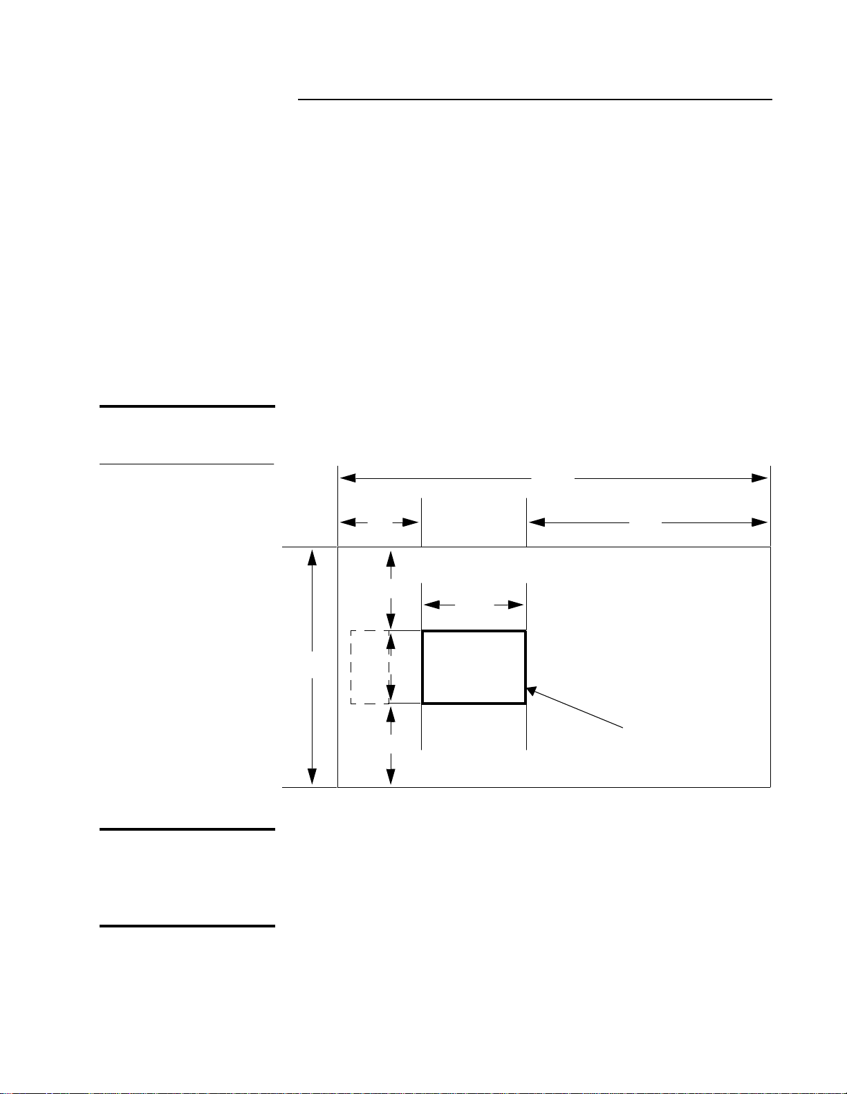
Chapter 1 Installation Requirements
31.12”
21.5”
Library
(Ramp Side/Off-load Area)
(For Maintenance Only)
(For Maintenance Only)
(Maintenance Area)
25”
25”
72”25”
128”
71”
Front of Library
Ventilation and
Cabling
Site Requirements
Floor Space
Figure 4 Floor Space
Requirements
Site Requirements
1
This section describes the following installation site requirements for
the library:
• Floor space
• Floor clearance
• Floor inclination
• Floor strength
•Power
•Grounding
1
Floor Clearance
Floor Inclination
1
The cabinet has a nominal floor clearance of 0.75 inch (1.9 cm). The
library should be placed on a level, uncarpeted floor free of cracks,
depressions, and so on.
1
The floor in the installati on site m ust be level to withi n 0.25 i nch over a
6 x 6 foot area.
ACL 4/52 Facilities Planning and Installation Guide
Page 20
Chapter 1 Installation Requirements
Site Requirements
Floor Strength
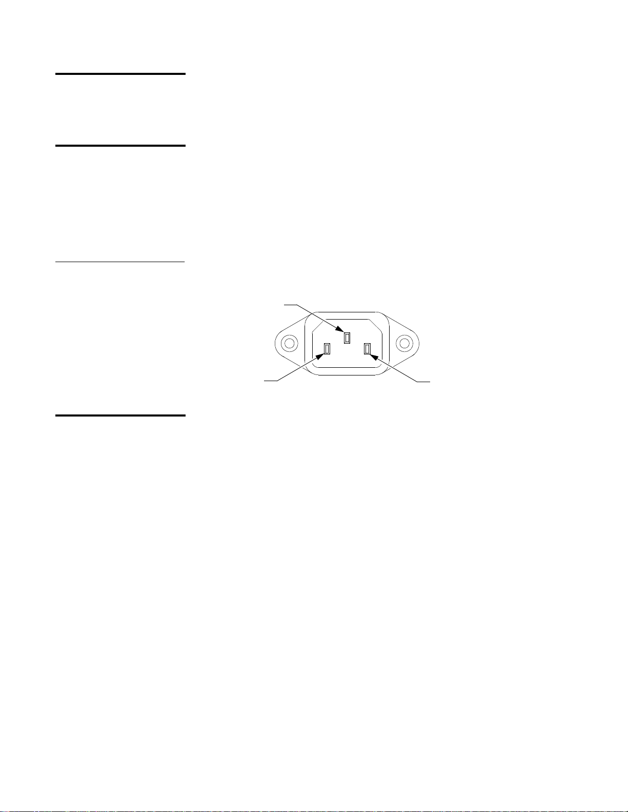
Power
Figure 5 Library’s AC
Power Receptacle
1
The floor in the installation site must be a standard raised computer
floor rated at 250 lb/ft
2
. This is sufficient to support a fully loaded
Enterprise library.
1
The library’s auto-ranging motor and logic power supplies accept
single-phase,
90–264 VAC input power at 47–63 Hz.
The power inlet connector is a IEC-320 connector. For international
applications you must replace the power cord set with a harmonized
3x2.0 mm
2
power cord set that is approved by the country where used.
~100-120V / ~200 - 240V
4A / 2A 50/60 Hz
IEC-320 Type
Ground
Line
Neutral
Grounding
1
The installation site must provide an earth ground cable for the library.
ACL 4/52 Facilities Planning and Installation Guide
Page 21

Chapter 2
Chapter 2 Unpacking the Library
Note:
Unpacking the Library
This chapter explains how to unpack and move the Enterprise library
to the final installation site.
Before following the instructions in this chapter, make sure the site
chosen for the library meets the requirements found in Chapter 1.
The procedures listed above must be performed in the order they
appear in this document. After completing these procedures, continue
the installation by following the instructions in Chapter 3.
2
ACL 4/52 Facilities Planning and Installation Guide
5
Page 22

Chapter 2 Unpacking the Library
Receiving the Library
Figure 6 Space Requirements
for Unloading
Receiving the Library
Follow these guidelines to properly receive the crated library:
Move the crated library as close to the final installation site as possible.
Allow a minimum of six feet in front of the off-load side of the pallet to
ensure that there is enough space to place the ramp used for removing
the library
Library
Pallet
Pallet Ramp
2
Unloading Area
(Minimum)
9'
24"
38"
32"
• Inspect the crate and packing materials for any damage that may
have occurred during shipment. Report any damage to the
shipping company immediately.
TA00129a
6 ACL 4/52 Facilities Planning and Installation Guide
Page 23

Chapter 2 Unpacking the Library
Unpacking the Library
Figure 7 Removing the
Box from the Pallet
Unpacking the Library
Caution: Use care when cutting the steel bands that secure the
library and packing materials to the pallet. These bands are
under tension and may snap when cut.
1 Cut the steel bands that secure the library and packing material to
the pallet (see figure7).
2 Lift the cardboard top cover off the pallet.
3 From the back of the container (opposite the ramp side), pull the
three cardboard retaining clips to their open position, and unwrap
the cardboard box from the library
Steel Bands
Top Cover
2
Ramp Side
(
Front/Off-load Side)
TA00139a
Cardboard Box
➀
Pallet
➁
Foam Cap and
Accessories Tray
➂
Retaining
Clip (x3)
TA00140a
4 Lift the foam cap and accessories tray off the library (see figure 8).
5 Remove the stop block located underneath the library.
ACL 4/52 Facilities Planning and Installation Guide 7
Page 24

Chapter 2 Unpacking the Library
Unpacking the Library
6 Slide out the two pallet ramp sections located underneath the
library and secure them to the pallet using the Velcro straps.
7 Carefully cut the shipping bag vertically along the heat-seal seam.
8 Inspect the library for damage that may have occurred during
shipment.
Figure 8 Unpacking the
Library
➄
Stop Block
➅
Pallet Ramp
Accessories Tray
➃
Foam Cap
Shipping Bag
8 ACL 4/52 Facilities Planning and Installation Guide
➆
Heat-Seal Seam
Page 25

Chapter 2 Unpacking the Library
TA00138a
Removing the Library from the Pallet
Removing the Library from the Pallet
Caution: The library weighs approximately 335 pounds. It is
recommended that at least two individuals perform the
following procedure.
To remove the library from the pallet:
1 Verify that all leveling feet (located on the underside of the library
at each corner of the cabinet) at in the up position.
If they are not, rotate each foot clockwise until it is fully retracted.
2 Guide the library out of the shipping bag and down the ramp (see
figure 9).
If two persons are available to do this, one should be positioned at
the front of the library to guide it down the ramp while another is
positioned at the back of the library to push the library forward.
Note: If you are the only person available to perform this procedure,
position yourself in front of the library so you can pull it
forward onto the ramp and carefully guide it to the floor. The
two-person procedure is recommended.
2
Figure 9 Rolling the
Library Off the Pallet
3 Save the shipping bag for future use.
ACL 4/52 Facilities Planning and Installation Guide 9
Page 26

Chapter 2 Unpacking the Library
Moving the Library to the Installation Site
Moving the Library to the Instal lation Site
Caution: The library weighs approximately 335 pounds. It is
recommended that at least two individuals perform the
following procedure.
To move the library to the installation site:
1 Prepare the path to the installation site.
The library has a nominal floor clearance of 0.75 inch (1.9 cm). Use
plastic or rubber mats to roll the library over carpeting, floor cracks
and depressions, or door jambs.
2 Verify that all leveling feet are fully retracted (in the up position).
If they are not, r otate each of the feet c lockwise until fully r etrac ted.
3 Roll the library to the final installation site.
Any side of the library can be used to push the library but the
preferred side to push from is the front of the library.
2
Caution: When pushing from the front, be car ef ul not to push on the
following nonstructural parts: load port door, control
panel, front door, or the front door handle.
10 ACL 4/52 Facilities Planning and Installation Guide
Page 27

Chapter 2 Unpacking the Library
Removing Internal Packing and Inserting Tape Cartridges
Removing Internal Packing and
Inserting Tape Cartridges
Once the library is in the final installation site, you must remove
internal packing materials and install any available tape cartridges as
explained in this section. The following are major steps in this
procedure:
• Removing the left cosmetic panel
• Removing tie-wraps
• Removing foam blocks
• Inserting tape cartridges
• Reinstalling the cosmetic panels
Caution: Make sure the library is at its final installation site before
removing the internal packing materials. Damage to the
equipment may occur if the library is moved without the
internal packing materials in place.
2
Removing the Left Cosmetic Panel
To remove the left cosmetic panel:
2
1 At the back of the library, remove the three screws that secure the
left panel to the library frame (see figure 10).
2 Pull the panel toward the back of the library to disengage the
retention tabs on the left side of the library frame and then take the
panel away from the library frame.
3 Set the left panel and the screws aside.
ACL 4/52 Facilities Planning and Installation Guide 11
Page 28

Chapter 2 Unpacking the Library
Removing Internal Packing and Inserting Tape Cartridges
Figure 10 Removing the
Left Panel
Left Panel
Left Panel
Retention Tabs
Removing the TieWraps
2
Note:
TA00137a
To remove the tie-wraps:
Do not cut the tie-wraps; they must be reused when packaging the
library for reshipment.
1 Use an antistatic wrist strap and take any other available antistatic
precautions.
2 Using figure 11, locate tie-wraps securing the horizontal carriage,
the vertical carria ge, and extension axi s.
3 To remove each tie-wrap, push on the release tab near the tie-wrap
buckle and then slide the end of the tie wrap out of the buckle.
Repeat this step until you have removed all three tie-wraps.
4 Save all tie-wraps for future use.
12 ACL 4/52 Facilities Planning and Installation Guide
Page 29

Figure 11 Removing TieWraps
Chapter 2 Unpacking the Library
Removing Internal Packing and Inserting Tape Cartridges
Gripper Motor
Horizontal
Carriage
Tie-Wraps
TA00046d
Removing the Foam Blocks
Extension Axis
Tie-Wrap
Extension Axis
Platform
Vertical Carriage
Tie-Wrap
H
H
Bumper Standoff
VIEW
H-H
To remove the foam blocks:
2
1 Use an antistatic wrist band and take any other available antistatic
precautions.
2 Gently slide the horizontal carriage toward the front of the library.
3 Remove the top and bottom horizontal carriage foam blocks.
4 Gently raise the vertical carriage and remove the vertical carriage
foam block.
5 Save all the blocks for future use.
ACL 4/52 Facilities Planning and Installation Guide 13
Page 30

Chapter 2 Unpacking the Library
Removing Internal Packing and Inserting Tape Cartridges
Figure 12 Removing the
Foam Blocks
Extension Axis
Horizontal Carriage
Horizontal Carriage
TA00136a
To Load Available Tape Cartridges
Top
Foam Block
Bottom
Foam Block
Vertical Carriage
Foam Block
2
Vertical Carriage
Horizontal
Carriage
ESD Ground Jack
(On Lower Panel Tab)
If the customer has tape cartridges available for loading at this time, it
is best to do this while the side panel is removed. You can insert up to
48 cartridges directly into empty bins in the fixed storage array.
Figure 13 shows how cartridges should be oriented before insertion
into a bin.
Figure 13 Tape Cartridge
Orentation
Cartridge Bar Code Label
14 ACL 4/52 Facilities Planning and Installation Guide
To the Bin
DLT Cartridge
Page 31

Chapter 2 Unpacking the Library
Removing Internal Packing and Inserting Tape Cartridges
Do not be concerned if the customer does not have all the cartridges
needed to fill the library. Additional cartridges can be added after
installation using the load port. For more information about this
procedure, refer to the Enterprise Tape Library 4/1800 Operator’s Guide.
Note: Whenever possible, try to fill the library completely with properly
labeled tape cartridges. A full library of labeled cartridges takes much
less time to inventory than a partially filled library or a library filled
with unlabeled cartridges.
Reinstalling the Left Cosmetic Panel
To reinstall the left cosmetic panel:
2
1 Rest the top lip of the left panel on top of the library frame.
2 Push the panel toward the front of the library and insert the frame
buckles into the retention tabs.
3 At the back of the library, insert the tighten the three screws that
secure the left panel to the back of the library frame.
ACL 4/52 Facilities Planning and Installation Guide 15
Page 32

Chapter 2 Unpacking the Library
Storing the Packing Materials
Storing the Packing Materials
After unpacking the library and removing internal packing materials,
you should store all materials for future use. Follow this procedure:
1 Raise the ramp and rest it on top of the pallet.
2 Collapse the cardboard box.
3 Store the box, foam cap, pallet, and all packing materials for future
use.
2
16 ACL 4/52 Facilities Planning and Installation Guide
Page 33

Chapter 2 Unpacking the Library
Packing the Library for Shipment
Removing Power from the Library
Packing the Library for Shipment
2
If it becomes necessary to ship the library, you must repack it in its
original shipping materials as explained in this section. The following
are the main steps in this procedure:
• Removing power from the library
• Removing the left cosmetic panel
• Unloading the library
• Installing the internal packing materials
• Replacing the cosmetic panels
• Moving the library onto the shipping pallet
• Securing the library to the pallet
To remove power from the library:
2
1 If necessary, unload and eject any tapes in the tape drives.
2 Turn off the library by setting the power switch to the O (off)
position.
Removing the Left Cosmetic Panel
3 Disconnect all SCSI cables from the back of the library.
Leave the power cord connected.
Caution:
Do not disconnect the power cord from the library or the
grounded power source until instructed to do so. While
plugged in, the power cord grounds the library chassis and
helps to prevent electrostatic discharge (ESD) damage.
To remove the left cosmetic panel:
2
1 At the back of the library, remove the three screws that secure the
left side panel to the library frame.
2 Pull the panel toward the back of the library (to disengage the
retention tabs) a nd then move the panel fr om the library frame (see
figure 10 on page 12).
Carefully set the left panel aside.
ACL 4/52 Facilities Planning and Installation Guide 17
Page 34

Chapter 2 Unpacking the Library
Packing the Library for Shipment
Unloading the Library
Installing the Internal Packing Materials
2
To unload the library:
1 Remove all tapes from the fixed storage bins.
To do this, grasp the exposed end of each tape and lift it out of the
bin.
2 Remove any tapes in the load port bins.
Load port bins are accessible from inside the library. To remove a
tape from the load port, grasp the exposed end and lift it out.
3 Remove any ejected tapes from the tape drives.
4 If you ejected any tapes prior to turning off the library, they may be
in the drive slots. Remove each t ape car eful ly fr om t he drive; make
sure the tape is completely unloaded (not buckled to the take-up
leader) before completely r e movin g it.
5 For more information, refer to the ACL 4/52 Operator’s Guide.
To install the packing materials:
2
1 Install the foam blocks as shown in figure 12 on page 14 and
explained below:
a Gently raise the vertical carriage and place the vertical carriage
foam block into position. Lower the vertical carriage onto the
foam block.
b Install both the top and bottom horizontal carriage foam
blocks.
c Gently slide the horizontal carriage toward the back of the
library and against the horizontal carriage foam blocks.
2 Install four tie-wraps to secure the extension axis, the vertical
carriage, and the horizontal carriage as shown in figure 11 on
page 13 and explained below:
a Route the two horizontal carriage tie-wraps through the notch
on the vertical rail and secure them through the notch on the
frame.
b Route the extension axis tie-wrap around and back up through
the extension axis platform and secure it around the gripper
motor.
Note:
Do not route the tie-wrap over the gripper motor power cable.
c Route the vertical axis tie-wrap under the bumper standoff and
secure it around the extension axis platform.
18 ACL 4/52 Facilities Planning and Installation Guide
Page 35

Chapter 2 Unpacking the Library
Packing the Library for Shipment
Reinstalling the Left Cosmetic Panel
Moving the Library onto the Shipping Pallet
To reinstall the left cosmetic panel:
2
1 Rest the top lip of the left side panel on the library frame.
2 Push the panel toward the front of the library and insert the frame
buckles into the retention tabs.
3 At the back of the library, insert and tighten the three screws to
secure the left side panel to the back of the library frame.
4 Unplug the power cord from the library and the power source.
To move the library onto the shipping pallet:
2
1 Raise the library’s leveling feet by rotating each foot clockwise
until fully retracted.
2 Position the pallet to load the library and secure the two ramp
sections to the pallet using the Velcro strips.
3 Unfold the shipping bag and align the white tape to the pallet
where the library casters will roll onto the pallet.
4 Roll the library onto the pallet and into the shipping bag.
5 Observe all cautions and guidelines in “Moving the Library to the
Installation Site” on page 10.
Securing the Library to the Pallet
6 Seal the shipping bag by folding the seam over and taping the
edge.
7 Disconnect the ramp sections from the pallet and slide them
underneath the library.
8 Install the stop block in front of the library front casters and secure
it to the Velcro fasteners.
To secure the library to the pallet:
2
1 Place all accessories (cables, manuals, installation hardwar e, and so
forth) in the accessories tray.
You must provide separate shipping container for the tape
cartridges.
2 Place the accessories tray and foam cap on top of the library (see
figure 7 on page 7).
3 Wrap the cardboard box around the library and secure it using the
cardboard retaining clips.
4 Place the cardboard top cover securely over the cardboard box.
5 Install steel bands to secure t he lib rary and packi ng materia l to the
pallet.
ACL 4/52 Facilities Planning and Installation Guide 19
Page 36

Chapter 2 Unpacking the Library
Packing the Library for Shipment
6 It is recommended that the steel bands be tightened to
approximately 200 pounds of tension.
7 Label the library for shipment.
20 ACL 4/52 Facilities Planning and Installation Guide
Page 37

Chapter 3
Chapter 3 Installing the Library
Installing the Library
This chapter explains how to install the ACL 4/52 library using the
following procedures:
To ensure a problem-free installation, these procedures should be
followed in order. The on-site system administrator should also be
present during these procedures.
3
ACL 4/52 Facilities Planning and Installation Guide
21
Page 38

Chapter 3 Installing the Library
Gathering Required Tools
Table 1 Required Tools
Gathering Require d Tools
Make sure you have the tools listed in table 1 before beginning this
installation.
Quantity Description
1 #2 Phillips s crewdriver
1Wire cutters
1Carpenter’s level
11
1 D igital voltmeter (DVM)
1 A ntistatic wristband
3
/8-inch open-ended wrench
3
22 ACL 4/52 Facilities Planning and Installation Guide
Page 39

Chapter 3 Installing the Library
Leveling the Library
Leveling the Library
Completing this task requires leveling one side of the library at a time,
moving in a clockwise direction from the front to the right side. To do
this:
1 Move the library into its final position for installation.
Make sure you leave enough floor space around the library for
removing cosmetic panels, attaching cables, opening the front
door, and so on. For minimum floor space dimensions, refer to
figure 4 on page 3.
2 Lower each foot of the library until it makes contact with the floor.
Caution: When adjusting the feet for leveling purposes, do not raise
any foot so high that excess weight is transferred to any
single caster.
3 Starting at the front of the l ibrary and mov ing fr om foot to foot in a
clockwise direction, rotate each foot clockwise so the
corresponding caster is raised approximately
1
/4 inch off the floor.
3
4 Place the carpenter’s level on top of the front edge of the library.
5 Check the gauge on the level. If the front of the library is level,
proceed to step 6. If it is not level:
a Determine the tilt of the library and adjust the appropriate foot
with the wrench, checking the gauge each time any foot is
rotated
1
/4 turn.
b Repeat step 5 until the front is level.
6 Repeat steps 4 and 5 to level the left side, the back side, and the
right side of the library.
7 Check each side again as follows:
a Starting at the front of the library, place the level on top of each
edge (front, left, back, and right) and check the gauge.
b Make any minor adjustments necessary to the feet to make the
side level.
8 Repeat step 7 until all four sides are level.
ACL 4/52 Facilities Planning and Installation Guide 23
Page 40

Chapter 3 Installing the Library
Setting Up and Testing the Library
Turning On the Library
Setting Up and Testing the Library
3
The following procedur es verify the proper operation of the ACL 4/52
library:
• Turning on the library
• Setting SCSI addresses
• Configuring library options
• Running a system test
• Performing an inventory
To turn on the library:
3
1 Verify the following:
• Actuators move freely in the horizontal and vertical directions
• All doors are closed
• All cosmetic panels are attached
Setting SCSI Addresses
Configuring Library Options
3
• Power switch in the O (off) position
Caution:
Using a digital voltmeter (DVM), verify that the facility
power is
90-132VAC or 180-264 VAC @ 47-63Hz before connecting
the AC power cord.
2 Connect the AC power cord to the rear panel and facility power.
3 On the rear panel, set the power switch to the “|” (on) position.
4 After several seconds, verify that the control panel displays li brary
status.
3
After power is applied to the library, you need to set library and tape
drive SCSI addresses. Setting SCSI addresses require operator- or
service-level security clearance at the library control panel.
In addition, you may want to change the default configuration (in
bold) of these options:
• Library power-up state (online/offline)
24 ACL 4/52 Facilities Planning and Installation Guide
Page 41

Chapter 3 Installing the Library
Setting Up and Testing the Library
• Auto clean (enable/disable)
• Retries (enable/disable)
• Exabyte emulation (enable/disable)
• Read barcode labels (yes/no)
• Auto inventory (yes/no)
• Auto load (enable/disable)
These procedures require operator- or service-level security clearance
at the library control panel. For a descripti on of these procedures, ref er
to the ACL 4/52 Operator’s Guide.
Performing a System T est
Performing an Inventory
The system test checks out the functionality of all library components.
3
To run the system test, you must have Service-level access at the
control panel.
The inventory command identifies tape c artridges by reading their bar
3
code labels and writes their location to nonvolatile RAM. To run the
inventory command, you must have either Operator- or Service-level
access at the control panel.
For more information about this command, refer to the ACL 4/52
Operator’s Guide .
ACL 4/52 Facilities Planning and Installation Guide 25
Page 42

Chapter 3 Installing the Library
Connecting the Host Computer
Connecting the Host Computer
This section explains how to connect the library to the Sun system
acting as host computer. The library is shipped with the internal
cabling configured for one host SCSI connection (single-wire).
Note: To support a SCSI configuration other than single-wire, the library’s
internal SCSI cabling must be changed. Additional SCSI cables are
provided in the library accessories kit . The accessories kit also incl udes
SCSI cables and terminator for connecting the library to the host
computer.
To perform this procedure:
1 Turn off the library as follows:
a Press the STANDBY button on the control panel. Make sure
that “System Offline” a ppears in the display and t he STANDBY
indicator is on.
b Press the STOP button on the control panel. Make sure that the
STOP indicator is on.
c At the back panel, set the power switch to the O (off) position.
3
2 Turn off all SCSI devices that will be connected to the same SCSI
bus as the library.
Note: The library uses differential (Diff) SCSI connections. If your
host adapter is single-ended (SE) SCSI, you must use an SE-to-
Diff converter for proper SCSI communication.
3 Connect a SCSI cable from the host computer’s SCSI adapter to
SCSI PORT 1 on the back panel of the library (figure 14 on
page 27).
4 Install the SCSI jumper cable between SCSI PORT 2 and SCSI
PORT 3 on the back panel of the library.
5 Install the SCSI terminator to SCSI PORT 4 on the back panel of the
library .
26 ACL 4/52 Facilities Planning and Installation Guide
Page 43

Figure 14 Cabling the
Library
Chapter 3 Installing the Library
Connecting the Host Computer
Note: Refer to the Sun Booklet for information on how to configure
the Sun system, to determine and set SCSI IDs, and to apply
power to the system.
DIAG
(RS-232 Diagnostic Port)
SCSI PORT 4
SCSI PORT 3
SCSI PORT 2
SCSI PORT 1
AC Power Receptacle
and Power Switch
SCSI Terminators
Host SCSI Cables
ACL 4/52 Facilities Planning and Installation Guide 27
Page 44

Chapter 3 Installing the Library
Connecting the Host Computer
28 ACL 4/52 Facilities Planning and Installation Guide
Page 45

Appendix A
Appendix A SCSI Cabling Options
SCSI Configurations
SCSI Cabling Options
This appendix describes the SCSI cabling options of the Enterprise
4/1800 tape library. The following SCSI devices are included in
communications between the host computer and library:
• Host computer
• Library robotics
• Tape drive 0
• Tape drive 1
• Tape drive 2
• Tape drive 3
1
In default configuration, internal single-wir e SCSI ca bling connects the
robotics controller and all of the SCSI devices on a single SCSI bus
from the host controller. Figure 15 shows this default configuration.
A
ACL 4/52 Facilities Planning and Installation Guide
29
Page 46

Appendix A SCSI Cabling Options
Figure 15 Single Wire
SCSI Configuration
(Default)
Tape Drive 0
*SCSI Address 2
Tape Drive 1
*SCSI Address 3
Robotics
Controller
*SCSI Address 0
EXTERNAL REAR PANEL
SCSI Termination
Tape Drive 2
*SCSI Address 4
Tape Drive 3
*SCSI Address 5
Tape Drive
Interface PWA
* - Indicates the “default” SCSI ID of the installed devices
The SCSI configuration of the tape drives and library can be changed
according to your needs by using the cable provided in the accessories
kit shipped with each library unit.
SCSI PORT 4
SCSI PORT 3
SCSI PORT 2
SCSI PORT 1
Host Connection
SCSI Termination
Host Connection
30 ACL 4/52 Facilities Planning and Installation Guide
Page 47

Appendix B Supplemental Installation Procedures
Appendix B
Supplemental Installation Procedures
The procedures contained in this appendix are provided for the Field
Service Engineer’s convenience during the installation of the library. If
there are additional tasks that you are asked to perform by the
customer’s System Administrator, refer to
4/52 Operator’s Guide
The following procedures are contained in this appendix:
•
Defining the library power-up state
•
Enabling/disabling the auto-clean option
•
Enabling/disabling the auto-load feature
•
Loading the library with cartridges (through the load port)
•
Performing an inventory
•
Turning the interior light on/off
.
Document No 6211222, ACL
B
Note:
The following procedures require familiarity of the library menu
mode.
ACL 4/52 Facilities Planning and Installation Guide 31
Page 48

Appendix B Supplemental Installation Procedures
Defining the Library Power-Up State
Defining the Library Power-Up State
You have the option of defining the starting condition of the library,
either
On-line
or standby (
initialization has occurred. The defa ult is
using the
1
Power-Up State
Press and release the Control Panel
that the SDA shows
2
Press and release the
3
Verify that the following is displayed in the SDA:
Menu:
Configuration..
4
Press and release the
menu.
5
Verify that the following is displayed in the SDA:
Menu: Configurati
Inquiry
Off-line
), after power-up, self-tests and
On-line
sub-menu as follows:
STANDBY
System Off-line
SELECT
SELECT
.
button to enter the Menu Mode.
button to choose the
. You can change it by
button and verify
Configuration
2
Note:
6
Use the
↓
button to bypass the
SCSI Address
menu and verify that
the following is displayed in the SDA:
Menu: Configurati
Power-Up State
7
Press and re lease the
SELECT
button to choose the
Power-Up State
menu and verify that the following is displayed in the SDA:
Menu: Power-Up
On-Line<
System On-line
state to standby mode (
is the default. If you want to change the power-up
System Off-line
), proceed to Step 8. Otherwise,
exit the menu mode.
8
Use the
↓
button to bypass the
On-Line
option and verify that the
following is displayed in the SDA:
Menu: Power-Up
Standby
9
W ith the desir ed option displayed on Line #2, press and release the
SELECT
button.
32 ACL 4/52 Facilities Planning and Installation Guide
Page 49

Appendix B Supplemental Installation Procedures
Defining the Library Power-Up State
10
Press and release the
↑
from the command.
11
Press and release the
↑
simultaneously, and verify that
is displayed in the SDA.
or ↓
button to clear the resulting display
or ↓
button and the
System On-line
SELECT
System Off-Line
or
button
ACL 4/52 Facilities Planning and Installation Guide 33
Page 50

Appendix B Supplemental Installation Procedures
Enabling/Disabling the Auto-Clean Option
Enabling/Disabling the Auto-Clean Option
The automatic drive cleaning feature has two modes of drive cleaning
support: Host Initiated and Fully Automatic.
In Host Initiated Cleaning Mode, drive cleaning is enabled by your
System Administrator at the host computer. Although the library unit
will internally track cleaning tape cartridge movement and use, the
library unit provides no cleaning support in this mode. The host is
responsible for all cleaning functions such as detecting when a drive
requires cleaning, tracking and selecting cleaning tape cartridges,
initiating media movement of the cleaning tape cartridge to the drive
and determining when a cleaning tape cartridge has been “used up.”
Drive cleaning in the Fully Automatic Cleaning Mode is also enabled by
your System Administrator at the host computer. However, in this
mode, the library unit monitors each drive’s status to determine when
a drive requires cleaning and initiates action when that determination
is made. In this case, the library unit selects an available cleaning tape
cartridge, handles media movement of the cleaning tape cartridge to
and from the drive and supervises the cleaning operation in the drive.
The library unit tracks cleaning tape cartridges within the library,
monitors cleaning tape cartridge use and determines when a cleaning
tape cartridge has been “used up.” A “used up” cleaning tape
cartridge is exported from the library to the load port under control of
the library.
2
The library is shipped with automatic drive cleaning disabled. If you
want this feature enabled, you can use the
follows.
1
Press and release the Control Panel
that the SDA shows
2
Press and release the
3
Verify that the following is displayed in the SDA:
Menu:
Configuration..
4
Press and release the
menu.
5
Verify that the following is displayed in the SDA:
Menu: Configurati
Inquiry
System Off-line.
SELECT
SELECT
button to enter the Menu Mode.
button to choose the
Auto Clean
STANDBY
sub-menu as
button and verify
Configuration
34 ACL 4/52 Facilities Planning and Installation Guide
Page 51

Appendix B Supplemental Installation Procedures
Enabling/Disabling the Auto-Clean Option
Note:
6
Press the
↓
button four (4) times to bypass the
Address, Power-Up Stat e,
Num of Drives
and
Inquiry, SCSI
menus. Then verify
that the following is displayed in the SDA:
Menu: Configurati
Auto Clean..
7
Auto Clean
With
release the
displayed on Line #2 of the SDA, press and
SELECT
button and verify that the following is
displayed in the SDA:
Menu: Auto Clean
Enabled
“Disabled” is the default. If you want to change the automatic cleaning
state to “Enabled,” proceed to Step 8. Otherwise, exit the Menu Mode.
8
W ith the desir ed option displayed on Line #2, press and release the
SELECT
9
Press and release the
button.
↑
or ↓
button to clear the resulting display
from the command.
10
Press and release the
↑
simultaneously, and verify that
or ↓
button and the
System On-line
SELECT
System Off-Line
or
button
is displayed in the SDA.
ACL 4/52 Facilities Planning and Installation Guide 35
Page 52

Appendix B Supplemental Installation Procedures
Enabling/Disabling the Auto-Load Feature
Enabling/Disabling the Auto-Load Feature
This feature of the ACL 4/52 library enables the operator to load
cartridges into the fixed storage array (FSA) without any intervention
from the host controller. When this feature is
automatically find bins in the FSA for cartridges that are placed in the
load port. If no bin locations are available in the FSA, the cartridges
will be left in the load port bin and an error message will be displayed
on the control panel SDA.
The default configuration for this feature is Disabled. To enable this
feature on the library, perform the following procedures:
1
Press and release the Control Panel
that the SDA shows
2
Press and release the
3
Verify that the following is displayed in the SDA:
Menu:
Configuration..
4
Press and release the
menu.
System Off-line
SELECT
SELECT
button to enter the Menu Mode.
button to choose the
Enabled
STANDBY
.
, the library will
button and verify
Configuration
2
Note:
5
Verify that the following is displayed in the SDA:
Menu: Configurati
Inquiry
6
Press the
Address, Power-Up State, Num of Drives, Auto Clean
menus. Then verify that the following is displayed in the SDA:
7
With
the
the SDA:
“
Disabled” is the default state for the auto-load option. If you want to
change this feature to “Enabled,” proceed to Step 8. Otherwise, exit
the menu mode.
↓
button six (6) times to bypass the
Menu: Configurati
Auto Load..
Auto Load
SELECT
Menu: Auto Load
Disabled
displayed on Line #2 of the SDA, press and release
button and verify that the following is displayed in
Inquiry, SCSI
and
Retries
36 ACL 4/52 Facilities Planning and Installation Guide
Page 53

Appendix B Supplemental Installation Procedures
Enabling/Disabling the Auto-Load Feature
8
Use the
↓
button to bypass the
Disabled
option and verify that the
following is displayed in the SDA:
Menu: Auto Load
Enabled
9
W ith the desir ed option displayed on Line #2, press and release the
SELECT
10
Press and release the
button.
↑
or ↓
button to clear the resulting display
from the command.
11
Press and release the
↑
simultaneously, and verify that
or ↓
button and the
System On-line
SELECT
System Off-Line
or
button
is displayed in the SDA.
ACL 4/52 Facilities Planning and Installation Guide 37
Page 54

Appendix B Supplemental Installation Procedures
Cartridge/Tape Drive Compatibility
Table 2 Cartridge/Tape
Drive Compatibility
Cartridge/Tape Drive Compatibility
The ACL 4/52 library is capable of supporting the DLT 2000, DLT
4000, and DLT 7000 tape drives. The library is also capable of
supporting the CompacTape III and Compac Tape IV cartridges, which are
dark gray and black, respectively. When loading the library with
cartridges, observe the compatibility of cartridges and tape drives as
defined in table 2.
Cartridge Type
CompacTape III
Cartridge
CompacTape IV
Cartridge
DLT 2000
Tape Dr ive
Compatible Compatible Compatible
Not
Compatible
Caution: DO NOT USE CompacTape I , CompacTape II or CompacTape
IIIXT tape cartridges in this library.
DLT 4000
Tape Dr ive
Compatible Compatible
DLT 7000
Tape Dr ive
2
38 ACL 4/52 Facilities Planning and Installation Guide
Page 55

Appendix B Supplemental Installation Procedures
Loading the Library wit h Cartridges
Loading the Library with Cartridges
Note: The “Auto-Load” feature must be “Enabled” before performing this
procedure. If this feature is not currently Enabled, refer to
“Enabling/Disabling the Auto-Load Feature” on page 36.
Caution: Examine all cartridges before loading them into the library
or tape drive. Look for label stock or other foreign material
that may be clinging to the cartridges.
1
With the SDA displaying
load port OPEN
button and verify that the indicator begins
blinking. (After several seconds, the load port door will
automatically open.)
Warning: Mechanical hazards could be exposed when the load port is
partially open or closed. Do not attempt to insert hands or
fingers into the load port opening at any time.
System On-line
, press and release the
2
2
With the load port door open, place up to four cartridges in the
available load port bins.
3
Press and release the
load port CLOSE
button.
Warning: The load port door is LOCKED in the “open” position. You
must press and release the CLOSE button before
attempting to close the load port door.
4
When the
CLOSE
CLOSE
Indicator (LED at the upper left corner of
button) is steadily lit, push the Load Port door closed. (The
library will lock the door.)
5
Repeat Steps 1 through 4 until you have loaded a maximum of 48
DLT™ cartridges into the library.
ACL 4/52 Facilities Planning and Installation Guide 39
Page 56

Appendix B Supplemental Installation Procedures
Loading the Library with Cartridges
Figure A-1: Loading
Cartridges Through the Load
Port
DLT Cartridge
Cartridge Bar Code Label
Load Port
opens to right/
closes to left
Load Port
(shown open)
OPEN & CLOSE Buttons
TA00010d
40 ACL 4/52 Facilities Planning and Installation Guide
Page 57

Appendix B Supplemental Installation Procedures
Performing an Inventory
Performing an Inventory
This feature allows you to perform an inventory of the cartridges
contained in the library. The inventory information is then written to
nonvolatile RAM. To perform this function, use the
menu as follows:
6
Press and release the Control Panel
that the SDA shows
7
Press and release the
8
Verify that the following is displayed in the SDA:
System Off-line
SELECT
STANDBY
.
button to enter the Menu Mode.
Menu:
Configuration..
9
Press the
Control, Calibration, System Test
↓
button five (5) times to bypass the
Robot Control
and
verify that the following is displayed in the SDA:
Menu:
Diagnostics..
Inventory
sub-
button and verify
Configuration, Drive
menus. Then
2
Note:
10
Press and release the
SELECT
button to choose the
Diagnostics
menu and verify that the following is displayed in the SDA:
Menu: Diagnostics
Home All
11
Press the
↓
button five (5) times to bypass the
All, Status Actuator, Status Sensor
Move Actuator
and
Home All, Selftest
sub-menu s.
Then verify that the following is displayed in the SDA:
Menu: Diagnostics
Inventory
12
With
Inventory
displayed on Line #2, press a nd release the
SELECT
button.
With a full library, the inventory process will take less than three
minutes if all of the cartridges are properly bar code labeled. The
actual inventory time can take longer if the library is not completely
full or if any of the cartridges are not properly labeled. When the
library is full of unlabeled cartr idges the inventory process will take
over twenty-seven minutes to complete.
ACL 4/52 Facilities Planning and Installation Guide 41
Page 58

13
When the SDA displays the status of the inventory command
as shown below, the inventory is complete.
Menu:Inventory
SUCCESS
14
Press and r elease the
or ↓
↑
button to clear the resulting dis play
from the command.
15
Press and release the
↑
or ↓
button and the SELECT button
simultaneously, and verify that System On-line or Sys tem Off-
Line is displayed in the SDA.
A-42
Page 59

Appendix B Supplemental Installation Procedures
Turning the Inte rior Lig ht On/ Off
Turning the Interior Light On/Off
Note: The Interior light bulb is not operator replaceable. Notify your Field
Service Engineer to replace the bulb.
The library is normally shipped with the interior light set to the “On”
position. Use the following procedur e to t urn the interior light “On” or
“Off .”
Refer to
Figure -2.
1
Press the control panel
Off-line”
2
Press the control panel
is displayed in the SDA.
STANDBY
STOP
button.
button and verify that “
System
Warning: To prevent injury from moving components, always press
the control panel
STOP
button before opening the front
door.
3
Using a 5/32” hex wrench, unlatch the front door.
2
4
Open the library front door.
Note: The front door is the only access for manually turning the interior light
On or Off.
Note: Reach through the front door and set the light switch (located on the
far side of the light) to the desired position.
5
Close and latch the library front door.
6
Press (to release) the control panel
7
Press (to release) the control panel
that the library completes the initialization sequence, and
On-line”
is displayed in the SDA.
STOP
button.
STANDBY
button and verify
“System
ACL 4/52 Facilities Planning and Installation Guide 43
Page 60

Appendix B Supplemental Installation Procedures
Turning the Interior Light On/Off
Figure A-2: Turning the
Interior Light On/Off
(Shown in Off Position)
Power Switch
Interior Light
(Opens to Right)
44 ACL 4/52 Facilities Planning and Installation Guide
Front Door
TA00038d
Page 61

Appendix B Supplemental Installation Procedures
Turning the Inte rior Lig ht On/ Off
ACL 4/52 Facilities Planning and Installation Guide 45
Page 62

Appendix B Supplemental Installation Procedures
Turning the Interior Light On/Off
46 ACL 4/52 Facilities Planning and Installation Guide
Page 63

Glossary
Glossary
A
B
C
actuators
library to manipulate cartridges. These include the gripper,
extension axis, vertical and horizontal axes.
automated tape library
system for DLT tape cartridges.
bar code label
cartridges.
bar code scanner
extension axis that reads the cartridge bar code labels.
calibration
configuration required for successful operation of the
library.
CHM
control panel
contains the status display area, as well as indicato rs and
control buttons.
Robotic components that move inside the
A robotic storage and retrieval
The identification label on DLT tape
A device that is mounted on the
The software measurements and
Cartridge handling mechanism
The panel on the front of the library that
D
E
DLT
Digital linear tape
EIA/TIA-574
protocol standard for nine pin connectors, sometimes
referred to as RS-232. The diagnostic port (
rear of the library, uses this protocol.
A serial communications cabling and
DIAG
), on the
47 ACL 4/52 Facilities Planning and Installation Guide
Page 64

Glossary
extension axis assembly Mounted onto the vertical axis,
the extension axis assembly consists of the gripper
assembly and the horizontal axis on which the gripper
assembly is mounted.
extension axis belt The drive belt connecting the
extension motor/gearbox to the gripper.
F
G
H
L
FCC Class A Standard established by the U.S. Federal
Communications Commission governing electromagnetic
emissions.
FSA Fixed storage array. This is a 3-column by 16-row
fixture mounted inside the library. Its purpose is to store up
to 48 cartridges in the library.
FSE Field service engineer
gripper assembly The assembly that mounts on the
extension axis and grips cartridges, referred to as the
gripper.
horizontal belt The drive belt connecting the horizontal
motor to the horizontal axis assembly.
host Host computer
host computer The computer t hat issues SCSI commands
to control the library robotics.
Load Port The operator accessible component of the
library that allows up to four cartridges to be
import/export loaded and unloaded into/from the library.
N
O
NVRAM Nonvolatile RAM
offline Not ready for communications with a host. This
mode is required for configuration, diagnostic, and
maintenance operations.
48 ACL 4/52 Facilities Planning and Installation Guide
Page 65

online Ready for communications with a host.
Glossary
P
PC Personal computer
pick The act of removing a cartridge from one location in
preparation for placing it in another location.
place The act of placing a cartridge in a location after it
has been picked from another location.
PROM Programmable read-only memory
R
RAM Random access memory
rear panel The rear cosmetic panel of the library that
contains the AC power switch, AC power receptacle and
connectors for attaching external cabling to the library.
S
SCSI Small computer system interface. A
communications standard for attaching peripheral
equipment to computers.
T
tape drive The mechanism that reads and writes data
from and to a tape cartridge.
U
V
UL Underwriters Laboratories
vertical belt The drive belt connecting the vertical motor
to the vertical axis assembly.
vertical carriage assembly The crossbar and linear
bearings mounted on the vertical rails and all components
mounted on the crossbar.
ACL 4/52 Facilities Planning and Installation Guide 49
Page 66

Glossary
50 ACL 4/52 Facilities Planning and Installation Guide
Page 67

Index
Index
A
auto-cleaning
disabling
enabling 34
auto-load option
disabling
enabling 36
34
36
C
cartridge
compatibility 38
types 38
cartridges
loading
connecting the host compu t er 26, 27
cosmetic panels
removing
crating the library 19
39
11
G
grounding 4
H
host computer 26, 27
I
IEC-320 connector 4
installing foam block s 18
installing tie-wr ap s 18
inventory
25
elapsed time 41
performing 41
L
D
differential SCSI connector 26
E
Enterprise 15
F
Fixed storage array 48
foam blocks
installing
18
leveling the library 23
light
turning on/off
loading cartridges 39
43
M
moving the library 10
P
packing materials 7, 16, 18
power connector
power rating 4
power-up stat e
defining
4
32
51ACL4/52 Facilities Planning and Installation Guide
Page 68

Index
R
receiving the libr ary 6
removing cosmetic panels
removing the library fro m th e pallet 9
11
S
SCSI addresses 29
setting library 24
SCSI cabling 26, 27, 29
SCSI devices
SCSI II specification xv
SCSI ports 27
SCSI terminator
shipping the library 17, 20
single-ended SCSI connector 26
site requirements
floor clearance 3
floor inclination 3
floor strength
grounding 4
power connector 4
power rating
specifications, library 2
storing the packing materials 16
29
29
27,
4
3,
4
4
T
tape drive
compatibility 38
terminator
tie-wraps
installing 18
turning on the library
27
24
U
unpacking the library 7
52 ACL4/52 Facilities Planning and Installation Guide
 Loading...