

Page 1

OPERATING INSTRUCTIONS
model FW7Q, FW8R
Digital Receivers
model FW9T
Digital Transmitter
Digital Wireless TTL Flash and Camera Trigger
★ DESIGNED AND MANUFACTURED IN THE USA ★
Patent Pending
Page 2

Contents
Section . . . . . . .Description . . . . . . . . . . . . . . . . . . . . . . . . . . . . . . . . . . . . . . . . . .Page
1.0 . . . . . . . . . . .Introduction . . . . . . . . . . . . . . . . . . . . . . . . . . . . . . . . . . . . . . . . . . . . .4
2.0 . . . . . . . . . . .Channel Code and Zone set-up . . . . . . . . . . . . . . . . . . . . . . . . . . . . . .5
3.0 . . . . . . . . . . .Wireless Flash setup -- with or without on-camera Flash . . . . . . . . . .7
4.0 . . . . . . . . . . .Wireless Shutter Release (motor drive) . . . . . . . . . . . . . . . . . . . . . . . .8
5.0 . . . . . . . . . . .Mounting
6.0 . . . . . . . . . . .Changing Qflash settings via Wireless Remote . . . . . . . . . . . . . . . . .11
7.0 . . . . . . . . . . .Wireless QTTL
. . . . . . . . . . . . .& pre-flash Film Cameras . . . . . . . . . . . . . . . . . . . . . . . . . . . . . . . . .12
8.0 . . . . . . . . . . .Wireless TTL control for Film Cameras (non pre-flash) . . . . . . . . . . .14
9.0 . . . . . . . . . . .Wireless Auto mode for any Qflash without TTL Adapter . . . . . . . . .15
10.0 . . . . . . . . . .Remote Camera and Remote Off-Camera Flash Operation . . . . . . .16
11.0 . . . . . . . . . .Miscellaneous . . . . . . . . . . . . . . . . . . . . . . . . . . . . . . . . . . . . . . . . . .18
12.0 . . . . . . . . . .
Appendix A . . . .Sync-in connections- camera to Transmitter FW9T . . . . . . . . . . . . .21
Appendix B . . . .Sync-out connections- Receiver FW8R to flash . . . . . . . . . . . . . . . .22
Appendix C . . . .Shutter Release (motor drive) cords- Receiver FW8R to camera . . .23
Appendix D . . . .QTTL
Appendix E . . . .Miscellaneous connections . . . . . . . . . . . . . . . . . . . . . . . . . . . . . . . .24
Appendix F . . . .Specifications . . . . . . . . . . . . . . . . . . . . . . . . . . . . . . . . . . . . . . . . . . .25
Customer Service . . . . . . . . . . . . . . . . . . . . . . . . . . . . . . . . . . . . . . . . . . . . . . . . . . . . .26
Limited Warranty . . . . . . . . . . . . . . . . . . . . . . . . . . . . . . . . . . . . . . . . . . . . . . . . . . . . . .26
FREEXWIRE Performance Guide . . . . . . . . . . . . . . . . . . . . . . . . . . .19
FREEXWIRE . . . . . . . . . . . . . . . . . . . . . . . . . . . . . . . . . . . .9
®
control for Digital Cameras
®
& TTL Wireless Adapters for Transmitter FW9T . . . . . . . . . .24
Glossary
Qflash 2 series . . . . . . . . . . . . . . .refers to models QFT2, QFT2d, QFX2, QFX2d
Qflash 4 series . . . . . . . . . . . . . . .refers to models QFT4d, QFX4d
Qflash 5 series . . . . . . . . . . . . . . .refers to models QFT5d, QFX5d
Receiver FW7Q . . . . . . . . . . . . . . .
. . . . . . . . . . . . . . . . . . . . . . . . . . . .series 4 and 5.
Receiver FW8R . . . . . . . . . . . . . . .
. . . . . . . . . . . . . . . . . . . . . . . . . . . .shutter release.
Transmitter FW9T . . . . . . . . . . . . .
Transceiver FW10 . . . . . . . . . . . . .
. . . . . . . . . . . . . . . . . . . . . . . . . . . .(can be set as transmitter or receiver).
Transceiver FW10w . . . . . . . . . . . .Upgraded FW10 incorporating the features of
. . . . . . . . . . . . . . . . . . . . . . . . . . . .Section 7.0.
Unimod FW11 . . . . . . . . . . . . . . . .Hot shoe adapter with additional sync inputs-
. . . . . . . . . . . . . . . . . . . . . . . . . . . .used with QF series TTL adapters
Hot Shoe Adapter FW12 . . . . . . . .
. . . . . . . . . . . . . . . . . . . . . . . . . . . .FW9T or FW10 on camera shoe
Zones 1, 2, 3, and 4 . . . . . . . . . . . .wireless links that can be turned on or off to
. . . . . . . . . . . . . . . . . . . . . . . . . . . .change lighting and camera activation
Channels 0 thru 7 . . . . . . . . . . . . .independent channels for separate
. . . . . . . . . . . . . . . . . . . . . . . . . . . .setups operating in the same area
Local, or on-camera flash . . . . . .a flash close to the camera and connected
. . . . . . . . . . . . . . . . . . . . . . . . . . . .with a sync cord
Remote flash . . . . . . . . . . . . . . . . .a flash at a distance from the camera and
. . . . . . . . . . . . . . . . . . . . . . . . . . . .wirelessly synchronized
FREEXWIRE Receiver dedicated for Qflash
FREEXWIRE Receiver for any flash or remote
FREEXWIRE Transmitter
FREEXWIRE Transceiver
FREEXWIRE hot shoe adapter to mount
FREEXWIRE
Included with FREE
Instructions, Hook and Loop mounting pads (cables and batteries not required))
Included with
Pole mounting kit, 2x AAAbatteries, Instructions, Hook and Loop mounting pads
Included with
2x AAAbatteries, Sync-in cord, Hook & Loop mounting pads, Instructions
Included with
FW8R, FW9T, and all accessories included with those models above
All specifications and features are subject to change, updating, and improvements.
WIRE FW7Q:
X
FREEXWIRE FW8R:
FREEXWIRE FW9T:
FREEXWIRE FW89 (set of Receiver and Transmitter):
FW Series Antenna Screw
Quantum Instruments, Inc. has made it easier
to identify different FW series products by
changing the color of the antenna screw.
Green - indicates FW8R Receiver
Red - indicates FW9T Transmitter
Black - indicates FW10w Transceiver
3
Page 3
1.0 Introduction
2.0 Channel Code and Zone set-up
We introduce the newest additions to the FREEXWIRE system: Receivers FW8R,
FW7Q and Transmitter FW9T. Transmitter FW9T emits higher power for extended
range. Receiver FW8R has extra sensitivity and simplified operation. FW7Q is dedicated to, and designed for any Qflash 4 or 5 series flash. FW7Q, FW8R and FW9T
are fully compatible with all other FREEXWIRE system components. Transceiver
FW10 may be upgraded for additional features of Section 7.0.
Wireless Sync, Wireless Shutter - Working with all popular flashes and cameras,
FREEXWIREs provide wireless sync for remote flash and/or wireless shutter control
for remote camera operation.
Wireless TTL flash control: FW8R, FW7Q and FW9T, in conjunction with Dw
series Adapters and Qflash 5d flashes, provide wireless “QTTL” flash control from
digital and film cameras. This wireless QTTL feature also transmits the “pre-flash”
signal utilized by many digital and film cameras to determine exposure values.
Qflash 4 series (QFT4d, QFX4d) can be upgraded to Qflash 5 series via software
update.
FREEXWIRE controls four independent Zones for wireless flash or wireless shutter
release. You can activate any one Zone, or any combination of Zones 1,2,3 and 4.
Switch your lighting instantly, remotely. Select and trigger flash, cameras, or combinations of them, from your remote position.
FREEXWIRE also has eight unique Channel Codes. FREEXWIRE units set to one
Channel cannot activate FREEXWIRE’s set to different Channels. You control the
Channel Code to make FREEXWIRE units work together or independently, as
required.
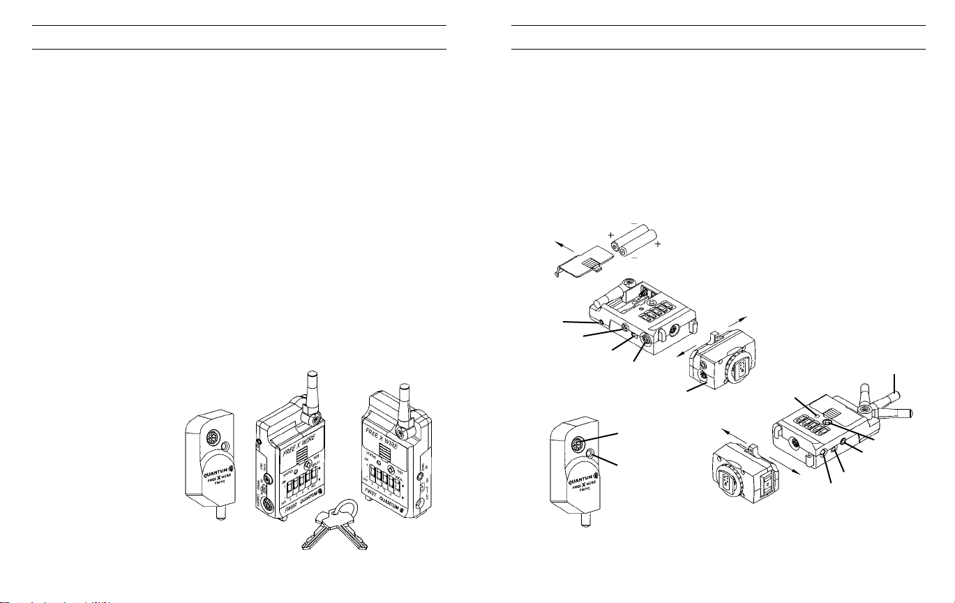
FREEXWIRE is very small
and light and mounts
easily to cameras, brackets, poles, and tripod legs.
Sync and Shutter Release
(motor drive) Cords are
available for popular cameras and flashes. You can
mount Transmitter FW9T
directly on a camera’s hot
shoe using optional
UniMod FW11or Hot Shoe
FW7Q
FW8R FW9T
Adapter FW12.
2.1 Setting the Channel Code and Zones
The Channel Codes allow FREEXWIREs to work together. Set all units that you
want to work together to the same Channel Code. If you desire independent groups
of FREEXWIREs (to work in the same area but not interfere), assign each group of
FREEXWIREs its own Channel.
The Channel dial is located on the left side of FW8R and FW9T, and on the front of
FW7Q. Rotate the dial to the desired Code, 0 through 7. To rotate, press the pad of
your thumb on the dial and turn. Or, use a small screwdriver. Channels can be
matched by number or by the position of the cutout in the Channel dial.
Install AAAbatteries (not required for FW7Q).
SHUTTER
RELEASE - MD
PC SYNC OUT
FW9T - TTL ON/OFF
FW8R - RANGE HI/NORM
FW7Q
CHANNEL CODE 0-7
CHANNEL
CODE
STATUS
LIGHT
UNLOCK
FW11 or FW12
UNLOCK
LOCK
FW8R, FW9T
STATUS
LIGHT
LOCK
ON/OFF
EXTERNAL
POWER
ANTENNA
TEST
FW8R SYNC OUT
FW9T SYNC IN
4
5
Page 4
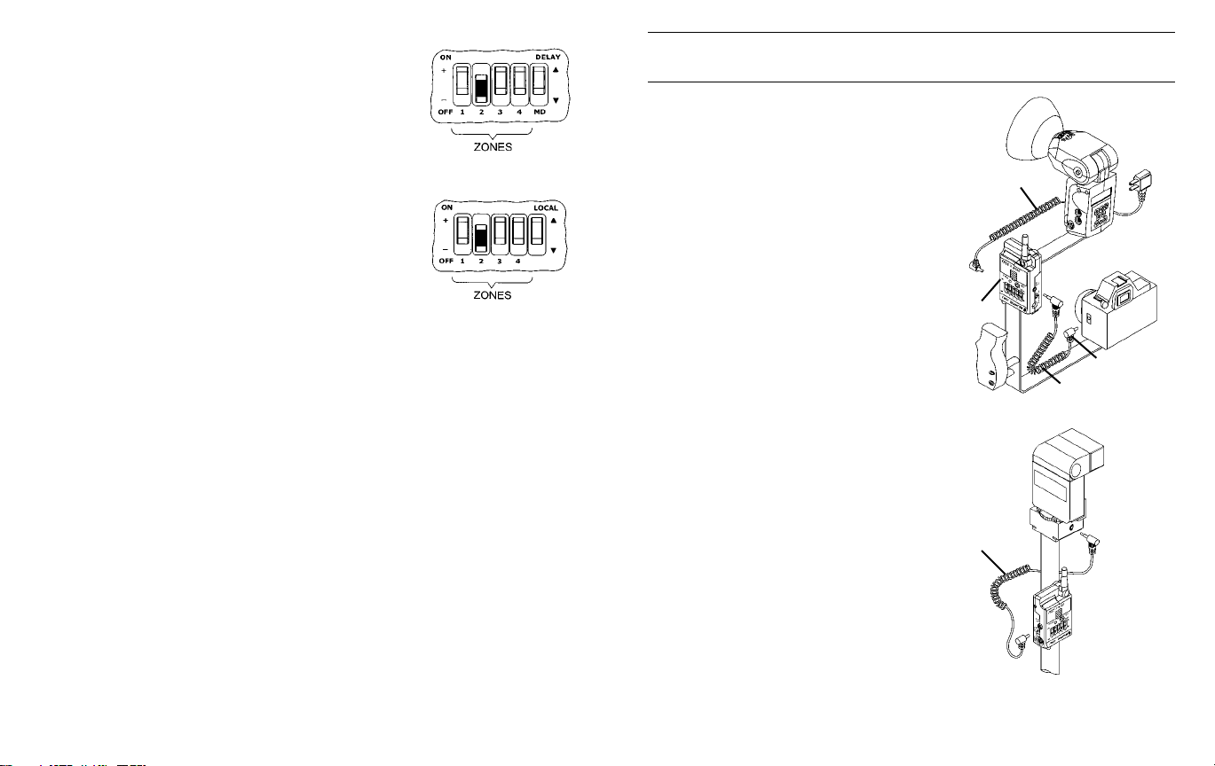
Activate at least one Zone on both FW8R and FW9T by
sliding Zone switches 1, 2, 3, and/or 4 up, towards the “+”
FW8R
symbol. Any FW8R and FW9TZones that match will activate FW8R units each time the FW9T unit transmits.
There are many possible combinations and you can
change them as you work. To deactivate a Zone slide its
switch down towards the “-“ symbol.
The FREEXWIRE FW7Q has no Zone Switch. When used
with a Qflash 4 series, FW7Q will activate for any Zone 1,
2, 3, or 4, on the matching Channel. However, Qflash 5
FW9T
series can set the Zone of FW7Q through its control panel.
(Note: Qflash 4 series can be upgraded to Qflash 5 series.
Please contact the Service Department at www.qtm.com).
To set the Zone on a Qflash 5 series, press the Option
button three times. The Zone Code settings should display
on Qflash screen. Use the Set button select a Zone, then
press the Up ▲ and Down ▼ buttons to turn the selected
Zone on or off.
2.2 Turn on the units
Slide the power switch to ON. The status light of FW9T blinks red, slowly. FW8R
units blink green, slowly. Low batteries are indicated by 3 quick blinks every few sec-
onds. Qflash 4 and 5 series power Receiver FW7Q which requires no batteries. The
green LED indicator on the FW7Q blinks once per second when Qflash is powered.
Open the antennas so that they are approximately vertical. See Section 5.0,
Mounting FREEXWIRE.
Press TEST on the Transmitter FW9T to confirm that all units are working. STATUS
should light steadily on all FREEXWIRE Receivers for as long as you hold TEST
(assuming correct Channel and Zone settings.)
2.3 Using FW9T test button to trigger a flash or shutter release:
For single shot operation, set the TTL switch of the FW9T “ON” when triggering a
remote flash, this is a one shot mode to prevent the flash from firing multiple times.
For continuos operation, set the TTL switch of the FW9T “OFF” when releasing the
shutter of a camera remotely.
3.0 Wireless Flash set-up with or without On Camera Flash
3.1 Transmitter FW9T
Connect the included (or other) sync-in
cord from your camera PC nipple to FW9T
Sync-In. Or use the optional FW11 or
FW12 to connect FREEXWIRE to your
camera’s hot shoe. (See Appendix A for
other sync-in options.)
If you want to sync an on-camera flash (in
addition to a wireless one) connect the
flash manufacturer’s PC sync cord to the
Sync-Out PC nipple on Transmitter FW9T,
and set the Local switch to (+). To turn off
the local flash, switch to (-).
If Qflash is the on-camera flash, connect
FW31 from Qflash to the FW9T bottom
socket (or FW11 DIN socket if used).
Then, Qflash can power the FW9T by setting the power switch to EXT , and batteries
are not needed.
3.2 Receiver FW8R
Connect the PC sync cord supplied by
your flash’s manufacturer to the Sync-Out
PC nipple or mini phone socket on the
FW8R. (See Appendix B for other syncout options.)
Generally set the RANGE switch to
NORM. Only if you require greater range,
set RANGE to HI. (See Section 11.0 for
range distances). However, whenever
using any FREEXWIRE for wireless
TTL, always use NORM range.
SYNC-OUT or
FW31 CABLE
PC
SYNC-OUT
CABLE
LOCAL FLASH
OPTIONAL
FW9T
PC
SYNC-IN CABLE
FW8R
6
7
Page 5

3.3 Wireless Qflash with Receiver FW7Q
This receiver is dedicated to Qflash series 4 and 5
and mounts directly onto the flash. Please see
Section 5.0 for proper mounting. FW7Q will be set
to NORM range when connected to a Qflash 4d.
When connected to Qflash 5d, range can be set to
HI or NORM, however, only NORM can be used for
wireless TTL (Sections 7 and 8). See Section 11 for
range specifications.
cameras require a delay between the meter/focus function and shutter release (for
example, Contax 645). Select Shutter MD Delay for those cameras by sliding MD
DELAYswitch to (+). Without Shutter MD Delay, the camera focus, meter, and shutter will be activated together (and the camera will shoot as soon as it can). The
Shutter MD Delay requires a two step Shutter Release Cord listed in Appendix C.
Shutter Release Cords will be added periodically; please consult your dealer or the
Quantum Web Site (qtm.com) for the latest models available.
4.4 Remote shutter operation is not possible with FW7Q.
FW7Q
4.0 Wireless Shutter Release (motor drive)
SHUTTER
RELEASE
CORD
4.1 Receiver FW8R:
Connect a Shutter Release Cord (see Appendix C) from the Receiver FW8R MD
connection to the camera shutter release connection.
4.2 Transmitter FW9T:
Press TEST and hold (up to 1 second ) to release the shutter. Test the camera -some require time to wake-up and to auto focus before they release the shutter.
4.3 Shutter MD Delay on FW8R:
Many cameras have two step shutter buttons: Pressing part way turns on the meter
and auto focusing, and pressing all the way releases the shutter. Some of these
8
FW8R
5.0 Mounting FREEXWIRE
FREEXWIRE units mount by several means:
5.1 Pole Mount Adapter 513: This item is included
with your Receiver FW8R. Attach it to the back of
FREEXWIRE and clamp it around any pole, leg, or structure where the antenna can be opened away from metal
objects.
FW8R/FW9T
5.2 Mounting directly to a bracket: Use the
#8/32 screw included with FREEXWIRE to
BRACKET
FW11
or FW12
OPTIONAL
DEAD SHOE
512
secure it through a hole in a bracket. Any other
screw used must protrude not more than 3/4”
(2 cm) into the FREEXWIRE case, or you will
damage FREEXWIRE!
When mounting the FW12 or FW11 to a Dead
Shoe (model 512) it will be necessary to connect a sync-in cable for FW9T units, or sync-out
cable for FW8R units. See Appendices Aand B.
513
9
Page 6
5.3: Direct Hot Shoe Mounting with FW12 or FW11
Connect the Hot Shoe Adapter FW12 or (Uni-Mod
FW11) to a Transmitter FW9T and slip it into a
camera hot shoe. The purpose of the Hot Shoe
Adapter is only to provide hot shoe mounting and
sync from a camera to a Transmitter FW9T.
FW9T
FW11 or FW12 will not provide TTLcontrol -- see
Appendix D for selection of QTTL and other TTL
adapters.
A Receiver FW8R mounted to FW11 or FW12 on
a camera shoe will have no connection to the
FW11, FW12
or FW SERIES
TTL ADAPTERS
SHOE MOUNT
shutter release. If you desire wireless shutter
release, connect a separate Shutter Release
Cord (see appendix C) between the FW8R MD
socket and the shutter release connection on the
camera.
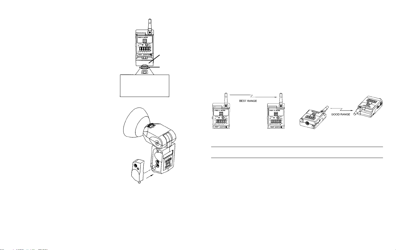
5.4 Mounting FW7Q
Turn off Qflash power before mounting the
FW7Q.
FW7Q plugs into the lower Accessory socket of
Qflash, as shown in the diagram. For added stability a hook-and- loop pad is mounted on the
back of Receiver FW7Q. One part of this pad will
be attached to the Qflash housing as follows:
Note where the hook and loop pad will come into
contact with the Qflash housing when FW7Q is
plugged into the lower Accessory socket. Clean
the area of any dirt or grease. Remove the adhesive liner from the pad (without touching the
MOUNTING FW7Q
adhesive), and align and mount FW7Q. Then
press the FW7Q housing firmly against Qflash so
that the hook and loop pad adheres to the Qflash housing. Do not remove FW7Q
for 24 hours to allow adhesive to cure.
You can now remove and re-mount FW7Q when you need to use it. Additional hook
and loop pads are included with FW7Q. They can be used to place additional pads
on other Qflash units, or as a replacement.
5.5: Mounting FW8R and FW9T with hook & loop tape:
Two sets of hook & loop fasteners and one mounting pad are included in the FW8R
and FW9T packages.
5.6: Important notes on antenna orientation:
During operation the antennas should not be left in the stored position!
At close range (about 50’ or 16m) antenna orientation is not critical. Antenna orientation matters more as distance between Transmitter FW9T and Receivers FW8R
and/or FW7Q increases.
The best mounting positions keep FREEXWIRE antennas away from metal objects.
Each antenna should be parallel to all others. Vertical FREEXWIREs with vertical
antennas provide the greatest range. Other orientations work almost as well. See
Section 11, FREEXWIRE Performance Guide, for more tips for ideal operation.
6.0 Changing Qflash Settings via Wireless Remote
This feature allows you to change the settings on a remote Qflash from the panel of
another Qflash, using Receivers FW7Q, FW8R or FW10 with Transmitters FW9T or
FW10. The settings on Qflash 4 and 5 series can be changed in this way. For example, you can change the ISO, mode, F#, manual power, and most all other Qflash
settings.
FW8R, FW10 and FW9T will need FW31 cables to connect each of them to the local
and remote Qflashes. (FW7Q connects directly and does not require the FW31
cable). The Qflash 4 and 5 series operating manuals give detailed instructions for
adjusting the settings on the remote Qflashes via wireless mode.
10
11
Page 7

7.0 Wireless QTTL control for Digital Cameras4.0
and pre-flash Film Cameras
Many newer camera systems utilize a “pre-flash” as a means to set exposure. After
the pre-flash the main flash fires and synchronizes with the shutter. FW7Q, FW8R
and FW9T provide wireless QTTL flash capability for these types of camera systems,
whether digital or film camera systems.
“Dw” series QTTL adapters (e.g. D12w, D13w, etc.) and Qflash series 5d flashes are required for the functions of this Section 7.0. Note: All Qflash 4d series
flashes can be converted to Qflash 5d series, and all D series adapters can be converted to Dw series via software upgrades. Please contact Quantum Customer
Service for the upgrade procedure.
If you wish to utilize FREEXWIRE FW10 transceivers together with FW7,8, or 9 units,
they require an upgrade to FW10w for the functions Sections 7.0 and 8.0. Please
contact Quantum Customer Service for the upgrade procedure.
FW10w can not be directly connected to Dw series QTTL Adapters (sections 7.1,
8.1). A local Qflash is required as illustrated in sections 7.3 and 8.3.
7.1 Transmitter FW9T set-up
Select the Dw series QTTL Adapter compatible with your camera (Appendix D, or
www.qtm.com for latest additions). Mount the Dw series adapter to the camera and
connect its cable to the FW9TAccessory socket. Mount FW9T on a bracket or other
convenient location.
Dw SERIES
FW9T
QTTL ADAPTER
7.2 Receiver FW8R or FW7Q set-up
Important: Set receivers FW7Q or FW8R to NORM range only for wireless TTL.
Set Qflash to TTL mode.
Connect FW31 Accessory Cable between the Receiver FW8R and either Qflash 5
series Accessory socket. Qflash powers FREEXWIRE, and batteries are not needed, when it is connected with the QF31 cable. Set the power switch of FW8R to EXT .
FW7Q plugs directly into a Qflash 5d series as described in Section 5.4.
QFLASH 5D
FW8R
FW31
MOUNTING FW7Q
7.3 Connecting a local Qflash to the Transmitter FW9T
If you wish to sync an on-camera Qflash 5 series with all remote Qflashes, connect
the “Dw” series TTLAdapter to either Qflash Accessory socket. Connect the FW9T
to the other Accessory socket with an FW31 accessory cable.
Set Qflash 5 series to QTTL
mode. Qflash cannot be deacti-
vated with the Local switch on
FW9T. However, Qflash 5 series
Dw SERIES
ADAPTER
can be turned off by pressing
MODE twice. To restart, press
any button on Qflash.
FW9T
12
FW31
Important:
On left side
of FW9T case
set TTL switch
to ON.
FW31
13
Page 8

8.0 Wireless TTL control for Film Cameras
4.0 (non pre-flash)
This mode allows a (non pre-flash) TTLcamera to control all local and remote Qflash
exposures. All series of Qflash and all series of TTL adapters can be used,
including QFT, X, T2, X2, T2d, X2d, 4 and 5 series, and TTLadapter series QF, FW,
D, and Dw.
Set all Qflashes, on-camera or remote, to TTL mode.
8.1 Transmitter FW9T set-up:
Select the correct type of Qflash TTLAdapter for your camera, from the list in
Appendix D or our website.
FW series of TTL adapters attach to Transmitter FW9T and to the camera
hot shoe without cables.
QF series TTLAdapters connect to Transmitter FW9T accessory socket and
require an FW11 Uni-Module.
D or Dw series QTTL adapters connect to Transmitter FW9T and DO NOT
require other accessories.
Set Transmitter FW9T TTL switch to ON. Mount FW9T on a bracket or other
location, or use an FW series Adapter which mounts directly to the camera hot shoe.
8.2 Receiver FW8R or FW7Q:
Mount and connect one or more of these receivers as in Section 7.2
8.3 Optional: connect a local Qflash to the Transmitter FW9T:
Alocal Qflash connected to FW9T will sync with the remote flash and will also power
the FW9T. Set the power switch of the FW9T to EXT. Set Qflash to TTL mode.
FW9T
FW31
14
QF, D or Dw
FW9T FW9T
FW31
SERIES ADAPTER
FW SERIES
TTL ADAPTERS
SHOE MOUNT
9.0 Wireless Auto Mode – for any Qflash – without
4.0 TTL Adapters
With today’s complicated camera systems, it is sometimes easier, more reliable and
straightforward to shoot in auto mode rather than TTL. Auto also gives the photographer the ability to tailor her/his exposures to personal taste or experience.
This mode will give any model of Qflash wireless Auto mode control of remote
Qflashes. This set up does not require a camera with TTL capability nor a TTL
Adapter, only local and remote Qflashes.
9.1 Transmitter FW9T set-up:
Connect an FW31 cable from Transmitter FW9T to Qflash. Connect a Sync-in cord
from camera PC nipple to Transmitter FW9TSync -in. Set the local Qflash to Auto
mode.
15
Page 9

9.2 Receiver FW8R or FW7Q:
Mount and connect one or more of these receivers as in Section 7.2. Connect as
many remote Qflashes as required. Set the remote Qflashes to TTL mode. The
remote TTL Qflashes will expose to the setting of the local “Auto” Qflash.
9.3 Additional features with Qflash 4 and 5 series & QTTL Adapters:
Many other Wireless Auto features are available when a Qflash 4 or 5 series is connected to the camera with a D or Dw series Adapter.
The available features include: Wireless ratio control between Qflashes; Wireless
auto-fill; Flash f/# tracking the camera’s f/# setting as it changes; Sensor limit with
any of the preceding modes. Full details of these features are found in the operating manuals for Qflash 4 or 5 and D series QTTL adapters. Operating manuals can
be found at qtm.com if needed.
10.0 Remote Camera and Remote Off-Camera
Flash Operation
Remote Camera and Remote off-camera Flash operation using Quantum
FREE
The new FW7Q, FW8R and FW9T are fully compatible with the FW10(w). These
units can be used together to setup remote camera and remote off-camera flash
operation. This setup releases a shutter wirelessly and the camera triggers a remote
flash timed to the shutter release. Careful settings are required for this setup to work.
When the TEST button of the FREEXWIRE™FW9T Transmitter is pressed, the
FREEXWIRE™FW10(w) [set as a receiver (RX)] Relay unit will activate the camera
shutter function. The camera will delay the flash sync until wake up, auto focusing,
metering, etc. is achieved (this may take up to a second or so), then the shutter opens
and the cameras’ flash sync activates the FREEXWIRE™FW10 RX Relay unit which
sends a signal to the (FW8R or FW7Q) Receiver and synchronizes (fires) the flash.
X
™
WIRE
FW8R (or FW7Q with Qflash T4d, T5d), FW9T and FW10(w).
FREE
WIRE™FW10(w) [set as a receiver (RX)] Relay unit set it to Relay mode L,
X
select Special Option for “TTL ON”, set the channel number the same as the
FREEXWIRE™TX unit, connect a sync-in cord from the cameras’ sync, or mount
it on the cameras’ hot shoe using a FW11 or FW12 shoe adapter. Connect a
shutter release cord (motor drive cord) from the FW10 to the cameras’ shutter
release connection.
FREEXWIRE™(FW8R or FW7Q) Receiver, set to NORM range, connect a sync-out
cord from the unit to the off-camera flash (not needed when using an FW7Q and
Qflash 4d/5d), set the channel Code one higher. For example if FREEXWIRE™TX
and FREEXWIRE™RX Relay are Code 5, set FREEXWIRE™RX to Code 6. If the
first Code TX unit is 7, the next higher Code is 0. Set a Zone “+” (on) which is also
selected on the TX unit.
• The confirmation signal is not possible for this setup.
•Wireless QTTL is not possible for Remote Camera and Remote off-camera
Flash operation.
• Multiple FREEXWIRE™Receivers can be used. Only the FW10(w) can be a
RX Relay unit. See FW10(w) section 8.3.
• Advance Setup with “local” flash and remote TTL or Auto control.
See FW10(w) section 8.4.
Basic setup:
FREEXWIRE™FW9T Tansmitter, set the TTL switch “OFF”, set it to any channel
Code 0 – 7, set the Zones “+” (on) that correspond to the FREEXWIRE™Receivers
that you want to fire.
16
17
Page 10

11.0 Miscellaneous
12.0 FREEXWIRE Performance Guide
11.1 High Speed Sync for remote flash:
For highest sync speeds: Turn on all zones of Receiver FW8R units. High speed
sync allows shutter speeds up to 1/500 for focal plane and 1/1000 for leaf shutters.
TTL mode does not work with high speed sync.
“Normal sync” speeds are 1/250 for focal plane and 1/500 for leaf shutters (or
slower) when selecting one, two or three of the Zones on any FREEXWIRE RX
unit.
11.2 External Power:
You can power FREEXWIRE externally with AC adapters, Quantum Batteries, or with
a Qflash connected by an FW31 Accessory cable. Appendix E lists AC adapters that
connect to the EXT power jack. To utilize external power, switch FREEXWIRE OFF
(EXT). When external power is removed, switch FREEXWIRE ON to power it from
its internal batteries.
Warning: Use only Quantum specified external power to avoid possibly damaging
FREEXWIRE.
How to maximize performance, troubleshoot, and answer questions about
Quantum’s FREEXWIRE Wireless Photo Control System.
If for some reason we don’t have an answer in this guide, please email, fax, write or
call Customer Service for further assistance.
Good radio performance depends on several factors: The orientation of a radio and
antenna, the presence of other radio signals which may interfere, and the presence
of objects which may interfere. As the range increases, these issues become more
important. At close range, performance is less critical.
The following suggestions will maximize range and reliability of your
FREEXWIRE link:
Orientation
The maximum range may be possible when all FREEXWIRE antennas are aligned
vertically. If FREEXWIRE is attached to a camera and you change from vertical to
horizontal framing, you can easily swing the FREEXWIRE antenna back to vertical.
When shooting quickly and changing from horizontal to vertical framing, you may get
good results the TX antenna at 45° as shown. That will provide reasonable range
without adjusting the antenna with every shot. The receiver antenna remain fixed
horizontally or vertically.
90˚
45˚
18
19
Page 11

Mounting and placement
The enemies of radio signals are metal objects, concrete, and water. Mount
WIREs away from metal objects when possible. Of course, you may be
FREE
X
mounting FREEXWIRE on light stands and brackets, and they generally have a
slight affect on range.
At longer distances it is possible to find dead spots. Moving the FREE
Remote unit a few inches in any direction can cure the problem.
X
WIRE
Do not use gaffers or duct tape which have metal threads imbedded, on any
FREEXWIRE. Do not mount metallic labels on the units.
When wearing FREEXWIREs, mount them outside your clothing and away from your
body. And, of course, watch out for metal objects on or near you.
Transmitter FW9T units may be mounted close together. FW9T units will trigger
FW8R units at a distance greater than 3 ft (1m) up to the maximum range.
These are the maximum ranges which may be possible under optimum conditions
(vertical antennas, no metal nearby, no nearby radio stations or interference, about
5’ above open field):
Transmitter Receiver HI Range* NORM Range (TTL)
FW9T FW8R 1000’ (300m) 500’ (150m)
FW9T FW7Q 600’ (175m) 300’ (90m)
FW10, as a transmitter or receiver, operates at approximately 1/2 of the distances above.
Notes:
* HI range is not recommended for pre-flash systems (digital TTL). HI range can
be used for flash sync, wireless shutter release, or for non pre-flash TTL control
(mostly film cameras). HI range for FW7Q is set via the QF5d panel.
Interference
Do lot locate FREEXWIRE receivers directly on studio flash power packs or other
equipment that generate radio frequency interference, such as most heavy machinery, motors, and of course other transmitters. Arenas, factories, and offices have
other sources of radio “noise” which can include TV camera uplinks, walkie-talkies,
radio and TV broadcast antennas, and cell phone repeaters.
If you cannot remove FREEXWIRE receivers from the area of interference:
Close or partly close the receiver (only!) antennas which will decrease inter-
ference. Set FW8R RANGE switch to NORM. Be aware that these measures
will necessarily decrease range as well as cut interference.
20
Appendices
Accessories may be changed or added periodically. Please consult you dealer
or the Quantum Web page (www.qtm.com) for the latest models available.
Appendix A – Sync-in connections from camera to Transmitter FW9T
Model Description From To Notes
434 Sync-in cord- 18” (.5m) Camera PC nipple
435 Sync-in cord- 4’ (1.2m) Camera PC nipple
470 Hasselblad sync cord Hasselblad “C” lens
FW11 Uni-Mod Camera hot shoe FW9T Accy conn
FW12 Hot Shoe Mount Camera hot shoe FW9T Accy conn
FW20 Sync-in cord- 18”(.5m) Camera PC nipple FW9T Accy conn
FW21 Hot Shoe sync- 18” (.5m) Camera hot shoe FW9T Accy conn
FW22 Hot Shoe sync- 18” (.5m) Camera hot shoe FW9T Sync-In
The following require an FW11 Uni-Mod connected to your Transmitter FW9T
unit. These Sync-in connections provide no TTL functions. See Appendix D
for D series adapters which provide additional TTL functions explained in
Sections 7 and 8.
536 Sync-in cord, 18” (.5m) Camera PC nipple Uni-Mod two prong Coiled cord
537 Sync-in cord, 5’ (1.5m) Hasselblad “C” lens Uni-Mod two prong Coiled cord
539 Sync-in cord, 12” (.3m) Camera PC nipple Uni-Mod two prong Straight cord
[Note: #536 and 537 serve as Sync-out cords as wel l- see Appendix B]
FW21
FW20
UNI-MODULE
QF53
536
537
539
FREEXWIRE
FREEXWIRE
FREEXWIRE
D SERIES QTTL ADAPTERS
Sync-In Included with FW9T
Sync-In Coiled cord
Sync-In
434
435
470
21
Page 12

Appendix B - Sync-out connections from FREEXWIRE FW8R to flash
Model Description From To Notes
---- flash mfg’s sync cord FREEXWIRE PC conn. Your flash Supplied by
flash mfg.
FW31 Accy cable 18” FREEXWIRE Accy conn. Qflash Accy For Qflash sync
(.5m) or wireless TTL.
434 Sync-out cord 18” FREEXWIRE Sync-out Flash PC nipple For Qflash and
(.5m) some studio flash
435 Sync-out cord 4’ FREEXWIRE Sync-out Flash PC nipple For Qflash and
(1.2m) some studio flash
534 Sync-out cord 18” FREEXWIRE PC conn. 2 prong For Studio flash
(.5m) -2 prong socket
535 Sync-out cord 5’ FREEXWIRE PC conn. 2 prong For Studio flash
(1.5m) -2 prong socket
536 Sync-out cord 18” FREEXWIRE PC conn. 2 prong + pin For Qflash and
(.5m) some studio flash
537 Sync-out cord 5’ FREEXWIRE PC conn. 2 prong + pin For Qflash and
(1.5m) some studio flash
541 Sync-out cord FREEXWIRE mini-phone 2 prong + pin For Qflash and
some studio flash
434
435
541
FW31
Appendix C - Motor Drive cords from FREEXWIRE to camera
Model Camera Notes
451 Nikon MD2/4/12/15, 8008s, F4S N90s, F5 need
Nikon adapter MC25
452 Hasselblad ELM, ELX
453 Canon, Olympus, Hasselblad H-1
See other Canon selections
454 Mamiya RZ67, RZ67 II, 645 Super, 645 Pro
456 Leica R3, R5, R6, R6-2, R7, RE
458 Minolta 5000, 7000, 9000, 5000i, 7000i, 8000i,
5Xi, 7Xi, 9Xi, 700si, Maxxum - 7,9
459 Canon EOS A5, A2E, A2, 1, 1N, 620,
T90, Rebel 300D
463 Bronica SQAI
464 Rollei, 6002, 6003, 6006, 6008, SLX
465 Hasselblad 503CW/CXi
466 Canon EOS 3, 1V, D30, D60, 10D, 1D, 1Ds,
1D Mark II
467 Mamiya 645AF
FW41 Contax 645, Canon Elan 2, 2E, 7, 7E,
Rebel 2000, XI Lite, Rebel 300D, Hasselblad H-1
Two step MD cord
FW42 Maxxum 7, 9 Two step MD cord
FW43 Canon 1v, 3, D2000, D30, D60, 10D, 20D,
1D, 1Ds, 1D Mark II Two step MD cord
FW44 Nikon D1, D1H, D1X, D2H, D2X, F5, N90/s,
F90x, F100 / Kodak DCS 760, Fuji S3 Two step MD cord
FW45 Mamiya 645AF Two step MD cord
FW46 Canon EOS 1, A2, A2E, AS, 1N, 620, T90 Two step MD cord
FW47 Pentax 645N and all Autofocus SLR Cameras
except Z-1p Two step MD cord
22
534
535
536
537
FW11 or
YOUR FLASH
SYNC CABLE
FW22
540
23
Page 13

Appendix D -- QTTL and TTL Wireless Adapters for Transmitter FW9T
These Adapters connect to a FREEXWIRE TX and provide wireless QTTL/TTL
exposure control.
D Series *** QF Series** FW Series*
QTTL Adapters TTL Adapters TTL Adapters Cameras
D10w QF10 Olympus, Practica
D12w QF12 FW52 Nikon, Fuji S2, S3
D13w QF13N FW53N Canon
D19w QF19 FW59 Hasselblad
D25w QF25 FW65 Mamiya 645AF, 645AFD
* FW series TTLAdapters connect directly to the FREEXWIRE TX
** QF series TTL Adapters require an FW11 Uni-Mod connected to FREEXWIRE TX,
unless a Qflash is also connected to the Accessory connector of FREEXWIRE.
*** D series QTTLAdapters provide the most features, including auto-focus, fill flash
offset, etc.
Adapters models may be changed or updated periodically. Please check the latest Quantum
Price List at your dealer, or www.qtm.com. Look under Qflash and
Appendix E - Miscellaneous Accessories
Model Description
MDC2 External power connection from QB1, 1+, or QB1c to FREEXWIRE.
XDC2 External power connection from Bantam or QB1c to FREEXWIRE.
FW26 Multi clip for FREEXWIRE to clip to a belt or bracket
FW29 AC external adapter, US & Can, 115 VAC.
QF11 Minolta X series
QF14 Minolta Xi series
QF15 Contax
QF16 Leica
QF17 FW57 Pentax
QF18 Rollei
QF20 FW60 Bronica
QF22 Mamiya 645 ProTL
QF23 Leica R8
QF24 FW64 Contax 645
FREEXWIRE.
Appendix F - Specifications
Size: FREE
Weight (w/ batteries): FW8R/FW9T: 4.3 oz. (122g)
Batteries: 2x AAAcell alkaline, nicad, nickel-metal hydride,
Battery life:(alkaline): FW8R: receiving four synchronizations per minute:
FW7Q requires no batteries. Any FREEXWIRE connected to Qflash with
FW31 cable requires no batteries.
Maximum Range: See Section 11.
Maximum flash rate: 25 fps
Maximum sync delay
from camera trigger
to remote flash: 1/2000-sec (normal sync); 1/3000 sec.
Minimum camera
shutter speeds: Leaf shutters 1/500, 1/250 focal plane shutters. In fast
All equipment, specifications and descriptions are subject to changes, improvements
and availability.
WIRE FW8R/FW9T: 3.6 x 2.3 x 1.1 in.
X
(9 x 6 x 2.8 cm)
FREEXWIRE FW7Q: 3.3 x 1.5 x 1.0 in.
(8.3 x 3.8 x 2.5 cm)
FW7Q: 1.8 oz. (51g)
or lithium
24000 shots, 100 hours;
FW9T: sending synchronizations shots per minute:
36000 shots, 150 hours
Remaining battery life- after low battery signal
(triple blink every 2 seconds): approx. 1-3 hours
(all RX Zones ON – fast sync mode).
sync mode (All RX Zones ON) sync speeds may be
1/1000 for leaf shutters, 1/500 for focal plane shutters.
24
25
Page 14

Customer Service
If you have any trouble whatsoever in using your Quantum product, we wish to assist
you in any way we can. Contact the Service Department via:
Telephone: (631) 656-7400 Fax: (631) 656-7410
Website: www.qtm.com
If you suspect a malfunction, return the unit with a detailed, accurate description of
the problem and the type and models of other equipment used with it. Please be
sure your problem is not caused by improper operating procedure or malfunctions in
your other equipment.
Carefully package and insure units sent for repair. For most reliable service send via
UPS, FedEx, or other common carrier to:
Service Department
Quantum Instruments Inc.
10 Commerce Drive
Hauppauge, NY 11788-3968
In case we have to contact you please provide your phone number and best time to
call, plus email address if desired.
An estimate of repair cost for out-of-warranty merchandise will be sent if desired.
This will require that we contact you for approval before proceeding and will delay
the return of your equipment. For fastest turn around, you may pre-approve repairs
up to a limit of $85 with your credit card. We will bill only the actual repair cost, and
you will be contacted if repairs exceed the pre-approved limit.
For pre-approved repair charges provide your Visa, MasterCharge, or American
Express card, expiration date, and billing address. Send this information via postal
mail or phone. DO NOT EMAIL THIS INFORMATION.
QFlash T2/X2, T4d/X4d ACCESSORIES
QF63T / QF36X
REMOTE FLASH HEAD
Limited Warranty
Quantum products have a one year limited warranty. Please refer to the Limited
Warranty card enclosed with your product for further details, conditions, and terms.
26
QFT5d/X5d
QF68
SOFTBOX
27
Page 15

OTHER QUANTUM PRODUCTS OTHER QUANTUM PRODUCTS
TURBO 2X2
28
QPAQ-X
TURBO COMPACT
FREEXWIRE
QB2
™
RADIO SLAVE
TURBO
QB1+
29
Page 16

30
31
Page 17

Tested to comply with FCC standards
FCC ID: CEXFW7Q CEXFW8R CEXFW9T
This device complies with Part 15 of the FCC Rules and with RSS-210
of Industry & Science Canada. Operation is subject to the following
conditions: 1) this device may not cause harmful interference, and
2) this device must accept any interference received including that
which may cause undesired operation of the device.
Changes or modifications to this equipment could void your authority to
use this product under the equipment authorization granted by the regulating agencies.
Declaration of Conformity: Quantum Instruments, Inc. declares that
WIRE FW10 satisfies all the technical regulations applicable to
FREE
X
the product within the scope of Council Directive 1999/5/EC.
For Customer Service, technical help, or information:
10 Commerce Drive, Hauppauge NY 11788-3968 USA
Tel: 1-631-656-7400 Fax: 1-631-656-7410
0
CANADA: 3707A-IC2811A
WIRE model FW7Q, FW8R, FW9T
FREE
X
IMPORTANT - CAUTION
Quantum Instruments, Inc
www.qtm.com
P604A
 Loading...