

Page 1

Quantum
Quick Start Guide
SDLT 220/320 Tape Drive
PROCEDURES
Getting Started - - - - - - - - - 1
Checking the Tape Drive 1
SCSI Setup 2
Connecting the Tape Drive 3
Confirming the Installation 4
Performing a Trial Backup 4
VORGÄNGE
Erste Schritte - - - - - - - - - - 5
Überprüfen des Bandlaufwerks 5
SCSI-Setup 6
Anschließen des Bandlaufwerks 7
Überprüfen der Installation 8
Durchführen eines Test-Backups 8
Configuración de SCSI 10
Conexión de la unidad de cinta 11
Comprobación de la instalación 12
Realización de una copia de
seguridad de prueba 12
PROCÉDURES
Démarrage - - - - - - - - - - - 13
Vérification du lecteur de bande 13
Configuration SCSI 14
Connexion du lecteur de bande 15
Confirmation de l'installation 16
Exécution d'un test de
sauvegarde 16
据え付け手順
PROCEDIMIENTOS
Introducción - - - - - - - - - - 9
Comprobación de la
unidad de cinta 9
Quick Start Guide SDLT 220/320 Tape Drive
はじめに - - - - - - - - - - - - - 17
テー プ ド ラ イ ブの動作確認 17
SCSI
テー プ ド ラ イ ブの接続 19
取 り 付け の確認 20
ト ライ アルバッ ク ア ッ プの実行 20
セッ トアップ 18
•
i
Page 2

절차
步骤
시작 - - - - - - - - - - - - - - - 21
테이프 드라이브 확인 22
SCSI
설정 22
테이프 드라이브 연결 23
설치 확인 24
시험 백업 수행 24
开始 - - - - - - - - - - - - - - - 25
检查磁带驱动器 25
SCSI
设置 26
连接磁带驱动器 27
确认安装 28
执行备份试验 28
ii
•
Quick Start Guide SDLT 220/320 Tape Drive
Page 3
Procedures
Getting Started
This guide describes how to install your tape drive. To get started:
a. Inspect the contents of the box.
If items are damaged, contact your tape drive provider.
b. Verify that the enclosed cable is compatible with the SCSI connector
on the host computer.
c. Confirm that the host computer’s SCSI controller card matches the
tape drive’s SCSI interface: single-ended, low-voltage differential
(LVD), or high-voltage differential (HVD).
A single-ended drive will not work with an HVD controller card,
and vice versa.
d. Verify that the backup software and operating system are compatible
with the new drive.
Visit www.dlttape.com for current compatibility information.
DFor more information about compatibility, refer to the
SDLT 220 and SDLT 320 User Reference Guide.
Checking the Tape Drive
For more information:
Refer to the documents on the
enclosed CD-ROM, or visit
www.quantum.com.
For help installing the tape
drive:
Contact Quantum Technical
Support at 1-888-827-3378.
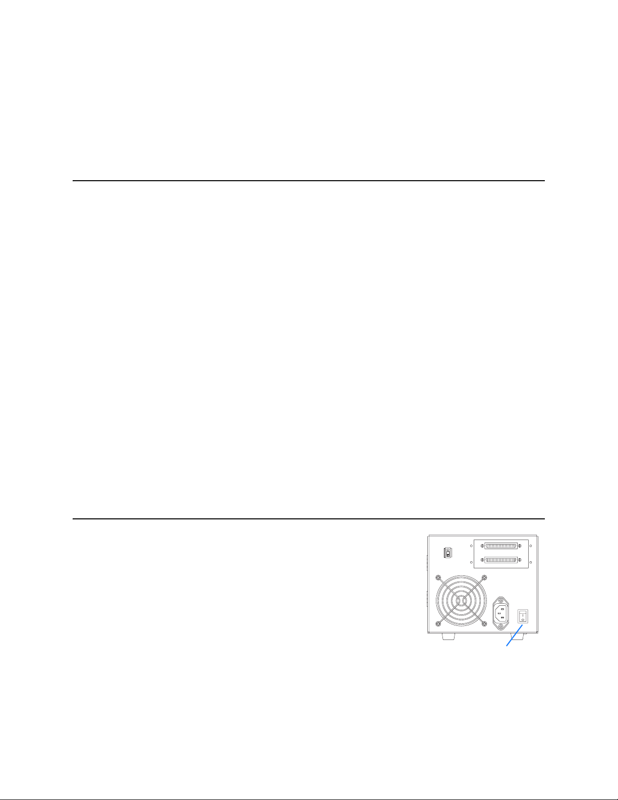
To check that the tape drive works and is not damaged:
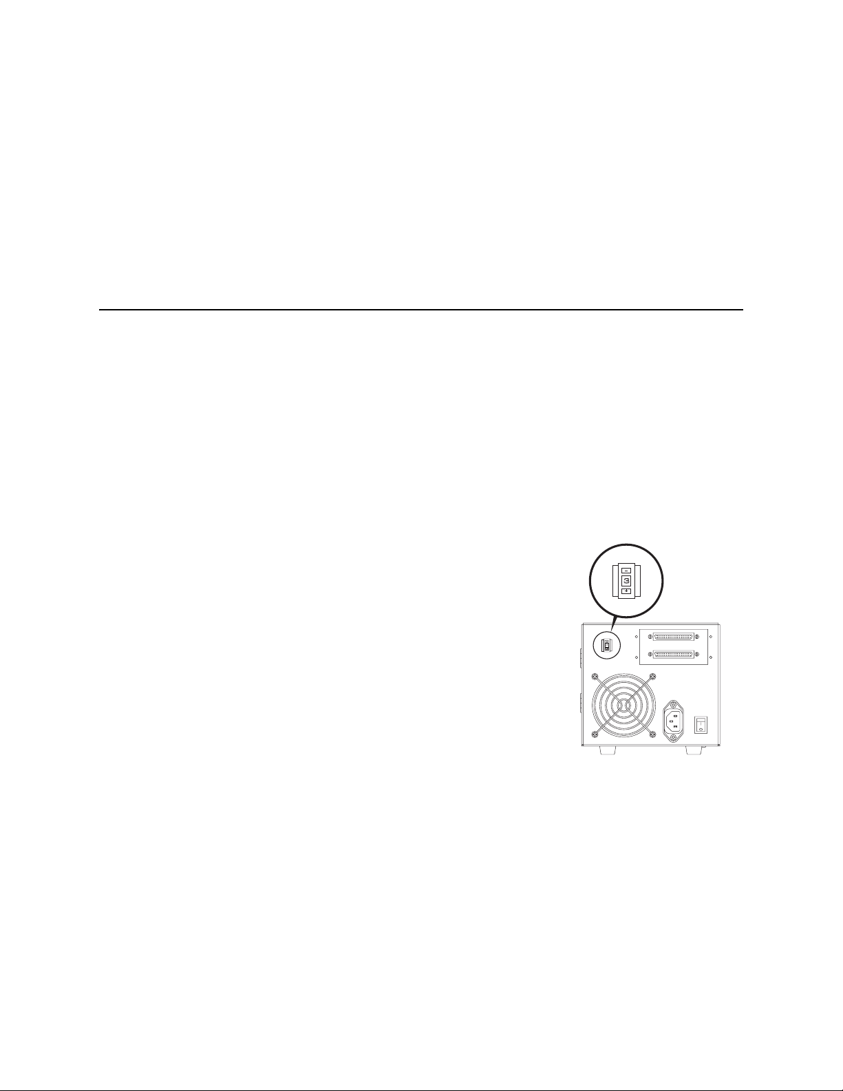
a. Connect the power cord to the tape drive and plug it into an AC
power source.
b. Power on the tape drive using the switch on the back the drive.
c. Monitor the tape drive’s Power-On Self-Test (POST) behavior and
messages displayed on your computer screen.
DFor more information about POST messages, refer to the
SDLT 220 and SDLT 320 User Reference Guide.
d. Power off the tape drive and unplug it from the AC outlet.
Getting Started
3
On/Off Switch
•
1
Page 4
SCSI Setup
3
Consider these factors when connecting your tape drive to the SCSI bus:
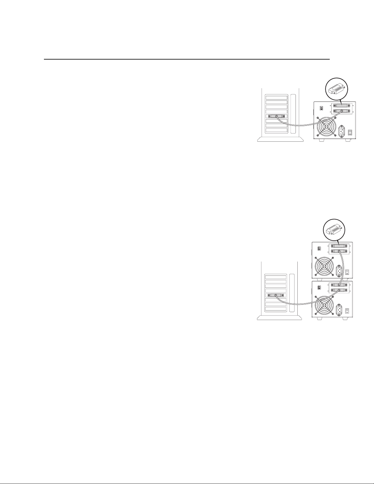
a. If the tape drive will be the only device connected to the SCSI bus,
attach the enclosed terminator to the upper SCSI connector on the
back of the drive. (Refer to illustration on page 3.)
The SCSI bus must be terminated at each end. The controller provides termination at one end, and the last device connected to the
bus must be terminated to complete the SCSI chain.
b. If you are inserting the tape drive into a SCSI daisy chain, ensure
that the last device on the chain is terminated properly.
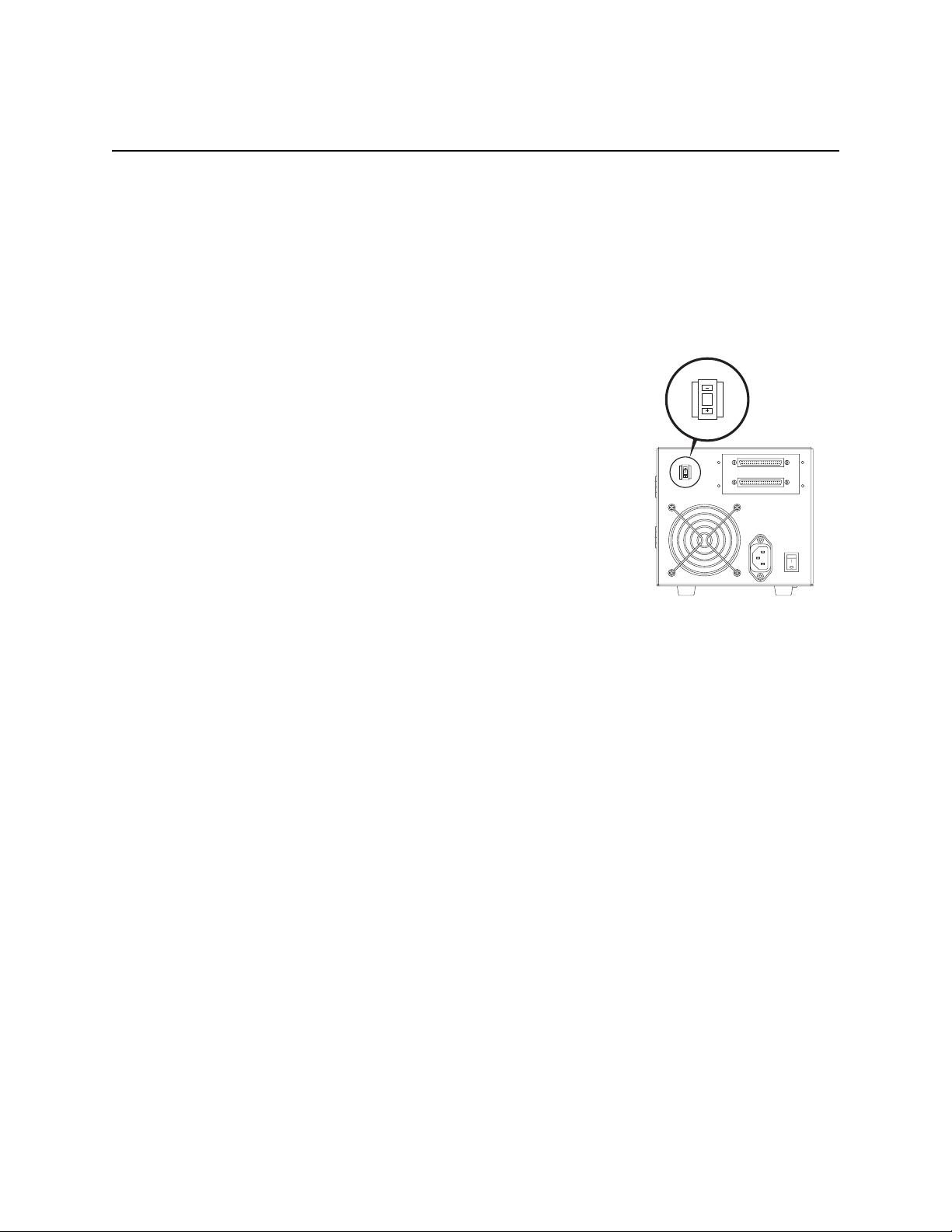
c. Each device (external or internal) attached to the SCSI bus must
have a unique SCSI ID. If necessary, change the SCSI ID of your
tape drive using the SCSI ID switch on the back of the drive.
The tape drive’s pre-set SCSI ID is 3. Change it if necessary.
! Do not use SCSI ID 7. It is typically used by the SCSI card.
SCSI ID Switch
3
2
•
SCSI Setup
Page 5

Connecting the Tape Drive
To connect the tape drive:
a. Before connecting your tape drive, make sure the tape drive and host
computer are powered off.
b. If you are daisy-chaining the drive, use the lower SCSI connector to
connect to the host computer, and the upper to connect to additional
devices.
If you plan to connect several devices to the SCSI bus, first connect
only the Super DLTtape drive to the host computer. This will confirm that the drive is communicating properly with the host before
adding additional devices.
c. Connect your tape drive to the host computer using the SCSI cable.
Check connections and ensure that they are attached correctly and
firmly seated.
DSee “Confirming the Installation” on page 4.
! You must terminate the SCSI bus by connecting a terminator to the last
device in the chain, as discussed on page 2.
Terminator
3
Cabling for Single Tape Drive
Terminator
3
3
Cabling for Daisy Chain
Connecting the Tape Drive
•
3
Page 6
Confirming the Installation
Follow these steps to confirm that the installation was successful:
a. Power on the tape drive and the host computer.
b. If your system displays BIOS, OS, and SCSI controller information
at startup, check to confirm that the host successfully recognizes the
tape drive.
c. Let the tape drive finish its Power-On Self-Test.
d. Launch your backup software.
e. Confirm that your backup software recognizes the tape drive.
Performing a Trial Backup
To perform a trial backup:
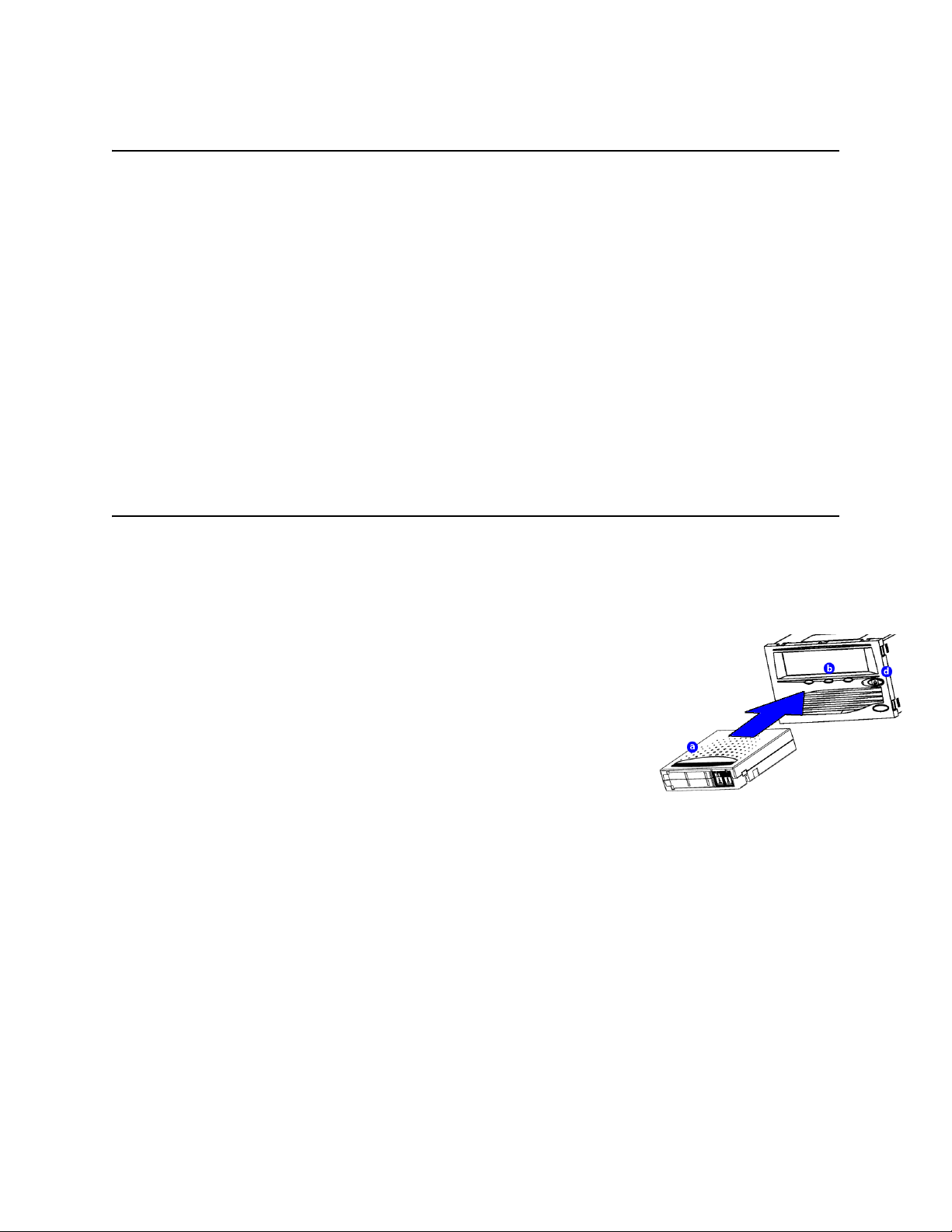
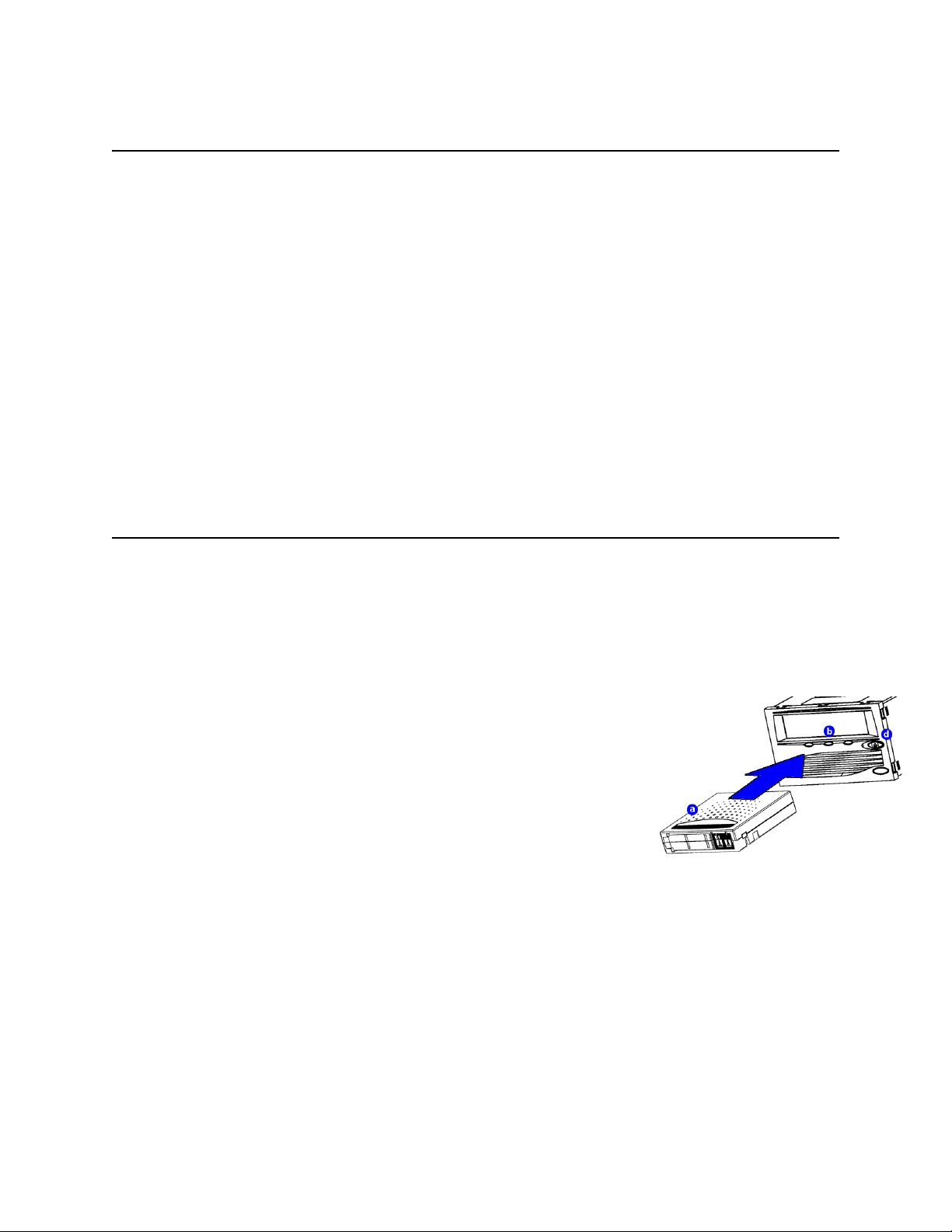
a. Insert a data cartridge into the tape drive. Ensure that you are using a
Super DLTtape I™ data cartridge, as shown in the illustration.
b. Push the data cartridge completely into the drive. The tape loads
automatically. The green LED lights steadily when the tape drive is
ready for use.
c. Do a trial backup.
Choose a sample file set from the host computer. Perform a backup
and then restore the file set. If the backup and restore complete without errors, you have installed the drive correctly.
d. To unload the cartridge, press the Eject button on the front of the
drive and remove the cartridge.
DFor troubleshooting information, refer to the SDLT 220 and
SDLT 320 User Reference Guide and the SDLT 220 and SDLT
320 Product Manual.
4
•
Confirming the Installation
Page 7
Vorgänge
Erste Schritte
In diesem Handbuch wird die Installation Ihres Bandlaufwerks beschrieben. Führen Sie die folgenden Schritte aus:
a. Überprüfen Sie den Inhalt Ihres Pakets.
Falls das Paket beschädigte Artikel enthält, wenden Sie sich an den
Händler, bei dem Sie das Bandlaufwerk erworben haben.
b. Überprüfen Sie, ob das im Lieferumfang enthaltene Kabel mit dem
SCSI-Anschluss am Hostcomputer kompatibel ist.
c. Vergewissern Sie sich, dass die SCSI-Controllerkarte des
Hostcomputers der SCSI-Schnittstelle des Bandlaufwerks
entspricht: Single-Ended, LVD (Low Voltage Differential) oder
HVD (High Voltage Differential).
Ein Single-Ended-Laufwerk funktioniert nicht mit einer HVDControllerkarte und umgekehrt.
d. Vergewissern Sie sich, dass die Backup-Software und das
Betriebssystem mit dem neuen Laufwerk kompatibel sind.
Unter www.dlttape.com erhalten Sie aktuelle Informationen zur
Kompatibilität.
Weitere Informationen:
Detaillierte Informationen
finden Sie in den Dokumenten
auf der im Lieferumfang
enthaltenen CD-ROM oder unter
www.quantum.com.
Hilfe beim Installieren des
Bandlaufwerks:
Wenden Sie sich an Quantum
Technischer Support unter
1-888-827-3378.
DWeitere Informationen zur Kompatibilität finden Sie im
SDLT 220 und SDLT 320 Benutzerhandbuch.
Überprüfen des Bandlaufwerks
Überprüfung der Funktionsfähigkeit des Bandlaufwerks:
a. Verbinden Sie das Netzkabel mit dem Bandlaufwerk, und stecken
Sie das andere Ende des Kabels in eine Steckdose mit Wechselstrom.
b. Schalten Sie das Bandlaufwerk mithilfe des Schalters auf der
Rückseite des Geräts ein.
Erste Schritte
3
Ein-/Aus-Schalter
•
5
Page 8
c. Beobachten Sie das POST-Test-Verhalten des Bandlaufwerks sowie
3
die Meldungen, die auf Ihrem Bildschirm angezeigt werden.
DWeitere Informationen über POST-Meldungen finden Sie
im SDLT 220 und SDLT 320 Benutzerhandbuch.
d. Schalten Sie das Bandlaufwerk aus, und ziehen Sie den Stecker aus
der Steckdose.
SCSI-Setup
Beachten Sie die folgenden Faktoren, wenn Sie Ihr Bandlaufwerk an
den SCSI-Bus anschließen:
a. Wenn das Bandlaufwerk das einzige Gerät ist, das an den SCSI-Bus
angeschlossen wird, verbinden Sie den im Lieferumfang enthaltenen
Abschlusswiderstand mit dem oberen SCSI-Anschluss auf der
Rückseite des Laufwerks. (Siehe hierzu die Abbildung auf Seite 7.)
Der SCSI-Bus muss an jedem Ende terminiert werden. Der
Controller bildet den Abschluss an einem Ende. Das letzte an den
Bus angeschlossene Gerät muss terminiert werden, um die SCSIKette zu schließen.
SCSI-ID-Schalter
b. Stellen Sie sicher, dass das letzte Gerät der Kette korrekt terminiert
ist, wenn Sie das Bandlaufwerk einer SCSI-Kette hinzufügen.
c. Alle Geräte (extern/intern), die an einen SCSI-Bus angeschlossen
sind, müssen eine eindeutige SCSI-ID aufweisen. Ändern Sie
3
gegebenenfalls mithilfe des SCSI-ID-Schalters auf der Rückseite
des Laufwerks die SCSI-ID. Die voreingestellte SCSI-ID des
Bandlaufwerks ist 3. Diese können Sie gegebenenfalls ändern.
! Verwenden Sie nicht die SCSI-ID 7. Diese wird normalerweise von der
SCSI-Karte verwendet.
6
•
SCSI-Setup
Page 9
Anschließen des Bandlaufwerks
Anschluss des Bandlaufwerks:
a. Prüfen Sie vor dem Anschließen des Bandlaufwerks, ob das
Bandlaufwerk und der Hostcomputer ausgeschaltet sind.
b. Wenn Sie das Laufwerk an eine Gerätekette anschließen, verwenden
Sie den unteren SCSI-Anschluss, um eine Verbindung mit dem
Hostcomputer herzustellen, sowie den oberen Anschluss, um eine
Verbindung mit zusätzlichen Geräten herzustellen.
Wenn Sie mehrere Geräte an den SCSI-Bus anschließen möchten,
schließen Sie zuerst nur das Super DLTtape-Laufwerk an den Hostcomputer an. Hierdurch wird sichergestellt, dass die Kommunikation zwischen Laufwerk und Host korrekt funktioniert, bevor
zusätzliche Geräte hinzugefügt werden.
c. Verbinden Sie Laufwerk und Hostcomputer mithilfe des
SCSI-Kabels. Prüfen Sie den korrekten Sitz der Verbindungen.
DSiehe „Überprüfen der Installation“ auf Seite 8.
! Sie müssen den SCSI-Bus terminieren, indem Sie einen Abschlusswiderstand an das letzte Gerät in der Kette anschließen, wie auf Seite 6
beschrieben.
Abschlusswiderstand
3
Verkabelung für
Einzelbandlaufwerk
Abschlusswiderstand
3
Anschließen des Bandlaufwerks
Verkabelung für
•
3
Gerätekette
7
Page 10
Überprüfen der Installation
Führen Sie die folgenden Schritte aus, um zu überprüfen, ob die Installation erfolgreich abgeschlossen wurde:
a. Schalten Sie das Bandlaufwerk und den Hostcomputer ein.
b. Überprüfen Sie gegebenenfalls beim Hochfahren des Computers die
BIOS-, Betriebssystem- und SCSI-Controller-Informationen, um
sicherzugehen, dass der Host das Bandlaufwerk erkennt.
c. Warten Sie, bis das Bandlaufwerk den POST-Test beendet hat.
d. Starten Sie die Backup-Software.
e. Überprüfen Sie, ob die Backup-Software das Bandlaufwerk erkennt.
Durchführen eines Test-Backups
Führen Sie die folgenden Schritte aus, um ein Test-Backup durchzuführen:
a. Legen Sie eine Datenkassette in das Bandlaufwerk ein.
Vergewissern Sie sich, dass Sie eine Super DLTtape I™-
Datenkassette verwenden, wie in der Abbildung dargestellt.
b. Drücken Sie die Datenkassette ganz in das Laufwerk. Das Band
wird automatisch geladen. Die grüne LED leuchtet kontinuierlich
auf, wenn das Bandlaufwerk betriebsbereit ist.
c. Führen Sie ein Test-Backup aus.
Wählen Sie mehrere Beispieldateien auf dem Hostcomputer. Führen
Sie ein Backup aus, und stellen Sie anschließend die Dateien wieder
her. Ist dies ohne Probleme möglich, haben Sie das Bandlaufwerk
erfolgreich installiert.
d. Wenn Sie die Kassette entladen möchten, drücken Sie die Auswurf-
taste auf der Vorderseite des Laufwerks und entnehmen Sie die
Kassette.
DInformationen zur Fehlersuche finden Sie im SDLT 220 und
SDLT 320 Benutzerhandbuch sowie in den SDLT 220 und
SDLT 320 Produktinformationen.
8
•
Überprüfen der Installation
Page 11

Procedimientos
Introducción
En esta guía se describe cómo instalar la unidad de cinta. Para empezar:
a. Examine el contenido de la caja.
Si alguno de los componentes está dañado, póngase en contacto con
el proveedor de la unidad de cinta.
b. Compruebe que el cable incluido es compatible con el conector
SCSI del equipo host.
c. Asegúrese de que la tarjeta del controlador SCSI del equipo host
coincide con la interfaz SCSI de la unidad de cinta: de extremo
único, diferencial de bajo voltaje (LVD) o diferencial de alto voltaje
(HVD).
Las unidades de extremo único no funcionan con tarjetas de
controlador del tipo HVD y vice versa.
d. Compruebe que el software de copia de seguridad y el sistema
operativo son compatibles con la nueva unidad.
Visite www.dlttape.com si desea obtener información sobre la
compatibilidad.
DPara obtener más información sobre la compatibilidad,
consulte la Guía de referencia del usuario de SDLT 220 y
SDLT 320.
Si desea más información:
Consulte los documentos
incluidos en el CD-ROM o visite
www.quantum.com.
Para obtener ayuda con la
instalación de la unidad de
cinta:
Llame al equipo de Asistencia
técnica de Quantum al número
1-888-827-3378.
Comprobación de la unidad de cinta
Para comprobar que la unidad de cinta funciona y no está dañada:
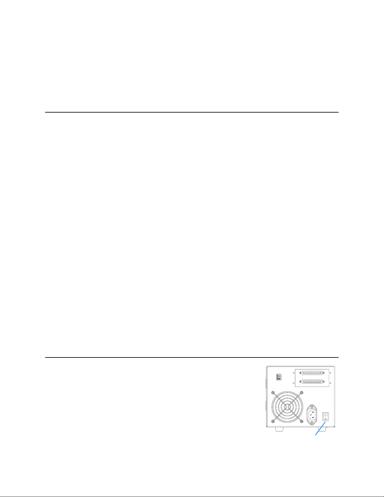
a. Conecte el cable de alimentación a la unidad de cinta y enchúfelo a
una salida de CA.
b. Encienda la unidad de cinta mediante el interruptor que se encuentra
en el panel posterior.
c. Monitoree la unidad mientras se lleva a cabo el autodiagnóstico y
revise los mensajes que aparezcan en la pantalla del equipo.
3
Interruptor de
encendido/apagado
Introducción
•
9
Page 12

DPara obtener más información sobre los mensajes del
3
autodiagnóstico, consulte la Guía de referencia del usuario
de SDLT 220 y SDLT 320.
d. Apague la unidad de cinta y desenchúfela.
Configuración de SCSI
Al conectar la unidad de cinta al bus SCSI, es necesario tomar en cuenta
lo siguiente:
a. Si la unidad de cinta es el único dispositivo conectado al bus SCSI,
conecte el terminador incluido al conector SCSI superior ubicado en
la parte posterior de la unidad. (Consulte la ilustración en la
página 11.)
El bus SCSI debe estar terminado en ambos extremos.
El controlador termina un extremo; el último dispositivo conectado
al bus se debe terminar para completar la conexión en cadena SCSI.
b. Si necesita agregar la unidad de cinta a una conexión en cadena
SCSI, asegúrese de que el último dispositivo de la cadena se termine
correctamente.
c. Cada uno de los dispositivos (externos o internos) que se conecte al
bus SCSI debe tener un identificador SCSI exclusivo. De ser
necesario, cambie el identificador SCSI de la unidad de cinta con el
conmutador ubicado en la parte posterior de la unidad.
El identificador SCSI predeterminado de la unidad de cinta es 3.
Cámbielo si es necesario.
! No utilice un identificador SCSI de 7. Por lo general, se usa para la tarjeta
SCSI.
Conmutador de
identificador SCSI
3
10
•
Configuración de SCSI
Page 13

Conexión de la unidad de cinta
Para conectar la unidad de cinta:
a. Antes de conectar la unidad de cinta, asegúrese de que tanto la
unidad como el equipo host estén apagados.
b. Para llevar a cabo una conexión en cadena, use el conector SCSI
inferior para conectar la unidad al equipo host, y el conector
superior, para conectar otros dispositivos que necesite.
Si tiene pensado conectar varios dispositivos al bus SCSI, primero
conecte sólo la unidad Super DLTtape al equipo host para estar
seguro de que la unidad se comunique correctamente con el equipo
host antes de agregar más dispositivos.
c. Conecte la unidad de cinta al equipo host con el cable SCSI.
Revise las conexiones y asegúrese de que estén bien sujetas.
DConsulte “Comprobación de la instalación” en la
página 12.
! Debe terminar el bus SCSI conectando un terminador en el último dispositivo de la cadena, tal y como se indica en la página 10.
Terminador
3
Cableado para una sola
unidad de cinta
Terminador
3
3
Cableado para conexión
en cadena
Conexión de la unidad de cinta
•
11
Page 14

Comprobación de la instalación
Siga estos pasos para comprobar que la instalación se ha realizado
correctamente:
a. Encienda la unidad de cinta y el equipo host.
b. Si al iniciar el sistema las pantallas del sistema muestran
información sobre el BIOS, el sistema operativo y el controlador
SCSI, compruebe que el equipo host reconozca la unidad de cinta
conectada.
c. Deje que la unidad de cinta finalice el autodiagnóstico.
d. Inicie el software de copia de seguridad.
e. Compruebe que el software de copia de seguridad reconoce la
unidad de cinta.
Realización de una copia de seguridad de prueba
Para realizar una copia de seguridad de prueba:
a. Inserte un cartucho de datos en la unidad de cinta. Asegúrese de que
esté usando un cartucho de datos Super DLTtape I™ como el que se
muestra en la ilustración.
b. Introduzca el cartucho de datos dentro de la unidad. La cinta se
carga automáticamente. Cuando la unidad de cinta está lista para
usarse, el indicador LED de color verde se enciende.
c. Haga una copia de seguridad de prueba.
Elija un conjunto de archivos de ejemplo del equipo host. Haga una
copia de seguridad del conjunto de archivos y restáurelo. Si la copia
de seguridad y la restauración se llevan a cabo sin ningún problema,
la unidad de cinta se habrá instalado correctamente.
d. Para descargar el cartucho, pulse el botón Eject (botón de expulsión)
situado en la parte frontal de la unidad y saque el cartucho.
DPara obtener más información sobre la solución de
problemas, consulte la Guía de referencia del usuario de
SDLT 220 y SDLT 320 y el manual del producto de SDLT 220
y SDLT 320.
12
•
Comprobación de la instalación
Page 15

Procédures
Démarrage
Ce guide décrit comment installer votre lecteur de bande. Pour
démarrer :
a. Inspectez le contenu de la boîte.
Si des articles sont endommagés, contactez le fournisseur de votre
lecteur de bande.
b. Vérifiez que le câble fourni est compatible avec le connecteur SCSI
sur l'ordinateur hôte.
c. Confirmez que la carte du contrôleur SCSI de l'ordinateur hôte
correspond à l'interface SCSI du lecteur de bande : asymétrique,
différentiel basse tension (LVD) ou différentiel haute tension
(HVD).
Un lecteur en mode asymétrique ne fonctionnera pas avec une carte
de contrôleur HVD et vice-versa.
d. Vérifiez que le logiciel de sauvegarde et le système d'exploitation
sont compatibles avec le nouveau lecteur.
Visitez le site à l'adresse www.dlttape.com pour obtenir des
informations à jour de compatibilité.
Pour de plus amples
informations :
Reportez-vous aux documents
du CD-ROM fourni ou visitez le
site www.quantum.com.
Pour obtenir de l'aide sur
l'installation du lecteur de
bande :
Contactez le service technique
de Quantum au
1-888-827-3378.
DPour obtenir de plus amples informations sur la
compatibilité, reportez-vous au Guide de référence
utilisateur du SDLT 220 et SDLT 320.
Démarrage
•
13
Page 16

Vérification du lecteur de bande
3
Pour vérifier que le lecteur de bande fonctionne et n'est pas
endommagé :
a. Connectez le cordon d'alimentation au lecteur de bande et branchez-
le sur une source d'alimentation secteur.
b. Mettez le lecteur de bande sous tension à l'aide de l'interrupteur situé
sur le panneau arrière.
3
c. Surveillez le comportement du test d'autodiagnostic (POST) du
lecteur de bande ainsi que les messages affichés sur l'écran de votre
ordinateur.
DPour obtenir de plus amples informations sur les
messages du test d'autodiagnostic, reportez-vous au Guide
de référence utilisateur du SDLT 220 et SDLT 320.
d. Mettez le lecteur de bande hors tension et débranchez-le de la prise
secteur.
Configuration SCSI
Prenez ces facteurs en compte lorsque vous connectez votre lecteur de
bande au bus SCSI :
a. Si le lecteur de bande est le seul périphérique connecté au bus SCSI,
reliez le terminateur inclus au connecteur SCSI supérieur à l'arrière
du lecteur (voir l'illustration page 15).
Le bus SCSI doit être muni d'une terminaison à chaque extrémité.
Le contrôleur fournit l'une des terminaisons et le dernier
périphérique connecté au bus doit être muni d'une terminaison pour
terminer la connexion la chaîne SCSI.
b. Si vous intégrez le lecteur de bande à une connexion en
cascade SCSI, vérifiez que le dernier périphérique sur la chaîne est
doté d'une terminaison adéquate.
Interrupteur
Marche/Arrêt
Commutateur de n°
d'identification SCSI
c. Chaque périphérique (externe ou interne) connecté à un bus SCSI
doit disposer d'un numéro d'identification SCSI unique. Si
nécessaire, modifiez le numéro d'identification SCSI sur votre
3
lecteur de bande à l'aide du connecteur situé à l'arrière du lecteur.
Le numéro d'identification par défaut du lecteur de bande est 3.
Changez-le si nécessaire.
! N'utilisez pas le numéro 7, car il s'agit du numéro utilisé par la carte SCSI.
14
•
Vérification du lecteur de bande
Page 17

Connexion du lecteur de bande
Pour connecter le lecteur de bande :
a. Avant de connecter votre lecteur de bande, assurez-vous que le
lecteur de bande et l'ordinateur hôte sont éteints.
b. Si vous connectez le lecteur en cascade, reliez-le à l'ordinateur hôte
à l'aide du connecteur SCSI inférieur et utilisez le connecteur
supérieur pour relier des périphériques supplémentaires.
Si vous prévoyez de connecter plusieurs périphériques au bus SCSI,
connectez d'abord le lecteur Super DLTtape à l'ordinateur hôte. Ceci
permet de confirmer que le lecteur communique correctement avec
l'hôte avant d'ajouter des périphériques supplémentaires.
c. Connectez votre lecteur de bande à l'ordinateur hôte à l'aide du
câble SCSI.Vérifiez les connexions et assurez-vous qu'elles sont
correctes et bien enfoncées.
DVoir « Confirmation de l'installation », page 16.
! Vous devez terminer le bus SCSI en reliant un terminateur au dernier
périphérique de la connexion en cascade, comme expliqué page 14.
Terminateur
3
Câblage d'un lecteur de bande unique
Terminateur
3
3
Câblage pour une
connexion en cascade
Connexion du lecteur de bande
•
15
Page 18

Confirmation de l'installation
Suivez les étapes suivantes pour confirmer que l'installation est
correcte :
a. Mettez le lecteur de bande et l'ordinateur hôte sous tension.
b. Si votre système affiche les informations sur le BIOS, le système
d'exploitation et le contrôleur SCSI au démarrage, vérifiez que l'hôte
reconnaît bien le lecteur de bande.
c. Laissez le lecteur de bande terminer son test d'autodiagnostic.
d. Démarrez le logiciel de sauvegarde.
e. Confirmez que le logiciel de sauvegarde reconnaît le lecteur de
bande.
Exécution d'un test de sauvegarde
Pour exécuter un test de sauvegarde :
a. Insérez une cartouche de données dans le lecteur de bande. Vérifiez
que vous utilisez une cartouche de données Super DLTtape I™,
comme indiqué dans l'illustration.
b. Enfoncez complètement la cartouche de données dans le lecteur. La
bande se charge automatiquement. Le voyant d'état reste allumé en
vert, sans clignoter, quand le lecteur de bande est prêt.
c. Effectuez un test de sauvegarde.
Choisissez un échantillon de fichiers sur l'ordinateur hôte. Effectuez
une sauvegarde, puis restaurez les fichiers. Si la sauvegarde et la
restauration ont lieu sans erreurs, le lecteur de bande est
correctement installé.
d. Pour décharger la cartouche, appuyez sur le bouton d'éjection à
l'avant du lecteur et retirez la cartouche.
DPour des informations de dépannage, reportez-vous au
Guide de référence utilisateur du SDLT 220 et SDLT 320 et au
manuel du produit SDLT 220 et SDLT 320.
16
•
Confirmation de l'installation
Page 19

据え付け手順
はじめに
このガイドでは、テープドライブを取り付ける方法について
説明します。まず次の点を確認してください。
a. パッケージ内のアイテムを確認します。
破損しているアイテムがあった場合は、テープドライブの
入手先に連絡してください。
b. 付属のケーブルとホストコンピュータの SCSI コネクタに
互換性があることを確認します。
c. ホストコンピュータの SCSI コントローラカードがテープ
ドライブの SCSI インタフェイス(シングルエンド低電圧
ディファレンシャル(LVD)または高電圧ディファレンシャ
ル(HVD))と適合することを確認します。
シングルエンドドライブと HVD コントローラカードを組み
合わせて使用することはできません。
d. バックアップソフトウェアおよびオペレーティングシステム
と新しいドライブに互換性があることを確認します。
互換性に関する最新情報ついては www.dlttape.com を参照
してください。
詳細 :
付属 CD-ROM に収録されて
いるドキュメント、 または
www.quantum.com を参照
してください。
テープド ライブの取り付けに
関するサポー ト :
電話で Quantum テクニカル
サポート (1-888-827-3378)
にお問い合わせください。
D
互換性について詳しくは『SDLT 220 & SDLT 320 ユーザー
リファレンスガイド』を参照してください。
テープドライブの動作確認
テープドライブが正しく動作し、損傷していないことを確認
するには、次の手順に従います。
a. 電源コードをテープドライブに接続し、プラグを AC コンセン
トに差し込みます。
b. ドライブの背面パネルのスイッチを使用して、テープドライ
ブの電源を入れます。
3
オン / オフスイッチ
はじめに
•
17
Page 20

c. テープドライブの自己診断テスト(POST)を実行して、コン
3
ピュータ画面に表示されるメッセージを確認してください。
D
POST メッセージについて詳しくは『SDLT 220 & SDLT 320
ユーザーリファレンスガイド』を参照してください。
d. テープドライブの電源を切り、プラグを AC コンセントから
抜きます。
SCSI
セットアップ
テープドライブを SCSI バスに接続する場合は、次の点を考慮
してください。
a. テープドライブが SCSI バスに接続された唯一のデバイスの
場合、同梱のターミネータをドライブの背面の上側の SCSI
コネクタに取り付けてください (19 ページの図を参照)。
SCSI バスは必ず両端で終端処理を行う必要があります。コン
トローラによって SCSI チェーンの一方の端が終端処理され
るので、バスに接続された末端のデバイスを終端処理して、
SCSI チェーンのもう一方の端を閉じる必要があります。
b. SCSI デイジーチェーンにテープドライブを接続する場合は、
チェーンの末端デバイスを必ず適切に終端処理してくだ
さい。
c. SCSI バスに接続する各デバイス(外部および内部とも)に
は、固有の SCSI ID 番号を割り当てる必要があります。必要
に応じて、ドライブ背面の SCSI ID スイッチを使用して、
テープドライブの SCSI ID を変更します。
テープドライブの工場出荷時の SCSI ID は 3 です。必要に
応じて変更してください。
SCSI ID ス イ ッ チ
3
!SCSI ID 7 は 通常、 SCSI カ ー ド 用に予約 さ れて い る番号なので使用 し な いで
ください。
18
•
SCSI
セットアップ
Page 21

テープドライブの接続
テープドライブを接続するには、次の手順に従います。
a. テープドライブを接続する前に、テープドライブとホスト
コンピュータの電源が切れていることを確認します。
b. ドライブをデイジーチェーン接続している場合、下側の SCSI
コネクタはホストコンピュータ用、上側のコネクタはその他
のデバイス用に使用してください。
SCSI バスに複数のデバイスを接続する場合は、まず Super
DLTtape ドライブのみをホストコンピュータに接続します。
こうすることによって、ドライブとホストコンピュータが
正常に通信することを確認してから他のデバイスを追加する
ことができます。
c. SCSI ケーブルを使用して、テープドライブをホストコン
ピュータに接続します。接続を点検し、正しく、しっかりと
差し込まれていることを確認します。
D
「取り付けの確認」(20 ページ)を参照してください
。
!18 ペー ジの説明 ど お り 、 デイ ジ ーチ ェ ー ン内の末端デバ イ スは、 タ ー ミ ネー タ
を接続 し て必ず終端処理す る必要があ り ま す。
ターミネータ
3
単一テ ー プ ド ラ イ ブの ケ ー ブル接続
ターミネータ
3
デイジーチェ ーンのケーブル接続
テープドライブの接続
3
•
19
Page 22

取り付けの確認
ドライブが正しく取り付けられていることを確認するには、
次の手順に従います。
a. テープドライブとホストコンピュータの電源を入れます。
b. システムの起動時に表示される BIOS、OS、SCSI コントローラ
の情報をチェックして、ホストでテープドライブが認識され
ていることを確認します。
c. テープドライブでハードウェアの自己診断テストが完了する
まで待ちます。
d. バックアップソフトウェアを起動します。
e. バックアップソフトウェアでテープドライブが認識されて
いることを確認します。
トライアルバックアップの実行
トライアルバックアップを実行するには、次の手順に従います。
a. 図に示すように、データカートリッジをテープドライブに挿
入します。必ず Super DLTtape I™ データカートリッジを使
用してください。
b. データカートリッジをドライブ内に押し込みます。テープは
自動的にロードされます。テープドライブが使用可能になる
と、緑色の LED が点灯します。
c. トライアルバックアップの実行。
ホストコンピュータでサンプルのファイルセットを選択しま
す。ファイルセットをバックアップしてからリストアしま
す。このバックアップとリストアが正常に完了すれば、ドラ
イブは正しく取り付けられています。
d. カートリッジをアンロードするには、ドライブ前面にある
イジェクトボタンを押して、カートリッジを取り出します。
D
トラブルシューティング情報については、『SDLT 220 & SDLT
320 ユーザーリファレンスガイド』と『SDLT 220 and SDLT 320
Product Manual』(SDLT 220 および SDLT 320 製品マニュアル)
を参照してください。
20
•
取り付けの確認
Page 23

절차
시작
본 안내서는 테이프 드라이브의 설치 방법을 설명합니다. 설치를
시작하기 전에 다음을 확인하십시오 .
a. 상자 내용물을 확인하십시오 .
손상된 물품이 있는 경우 테이프 드라이브 제공업체에 연락하
십시오 .
b. 등봉된 케이블이 호스트 컴퓨터의 SCSI 커넥터와 호환하는지
확인하십시오 .
c. 호스트 컴퓨터의 SCSI 컨트롤러 카드가 테이프 드라이브의
SCSI 인터페이스와 일치하는지 확인하십시오 . 즉 , 단일 종단
LVD 인지 , 아니면 HVD 인지 확인하십시오 .
단일 종단 드라이브는 HVD 컨트롤러와 작동하지 않으며 , 그
반대의 경우에도 작동하지 않습니다 .
d. 백업 소프트웨어와 운영 시스템이 새 드라이브와 호환하는지
확인하십시오 .
호환성에 대한 최신 내용은 www.dlttape.com 을 방문하십시
오.
참조 자료 :
제품 CD-ROM 에 포함된 설
명서를 참조하거나
www.quantum.com 을 방문
하십시오 .
테이프 드라이브 설치 문의 :
1-888-827-3378 로 연락하
고 Quantum 기술 지원을 문
의하십시오 .
호환성에 대한 자세한 내용은 SDLT 220 및 SDLT 320 사용 설
D
명서를 참조하십시오 .
시작
•
21
Page 24

테이프 드라이브 확인
3
테이프 드라이브의 작동 및 손상 여부를 점검하려면
a. 테이프 드라이브에 전원 코드를 연결하고 이를 AC 전원 콘센
트에 꽂습니다 .
b. 드라이브 후면에 있는 스위치로 테이프 드라이브를 켭니다 .
c. 테이프 드라이브의 POST(Power On Self Test) 작동과 컴퓨
터 화면에 표시된 메시지를 검토하십시오 .
POST 메시지에 대한 자세한 내용은 SDLT 220 및 SDLT 320 사
D
용 설명서를 참조하십시오 .
d. 테이프 드라이브를 끄고 AC 컨센트에서 분리하십시오 .
SCSI 설정
테이프 드라이브를 SCSI 버스에 연결시 고려 사항
a. 테이프 드라이브가 SCSI 버스에 연결되는 유일한 장치일 경우
등봉된 터미네이터를 드라이브 뒷면에 있는 상단 SCSI 커넥터
에 연결하십시오 (23 페이지의 그림 참조 ).
SCSI 버스의 양쪽 끝을 종료해야 합니다 . 컨트롤러는 한쪽 끝
에 종단을 제공하며 SCSI 체인을 완성하려면 버스에 마지막으
로 연결된 장치를 종단해야 합니다 .
3
켜기 / 끄기 스위치
SCSI ID 스위치
b. 테이프 드라이브를 SCSI 데이지 체인에 삽입할 경우 체인의
마지막 장치가 올바르게 종단되었는지 확인하십시오 .
c. SCSI 버스에 연결된 각 장치 ( 외장 또는 내장 ) 에는 고유의
SCSI ID 번호가 있어야 합니다 . 필요한 경우 드라이브 후면의
3
SCSI ID 스위치로 테이프 드라이브의 SCSI ID 를 변경하십시
오.
테이프 드라이브의 SCSI ID 는 3 으로 사전 설정되어 있습니
다 . 필요한 경우 이 설정을 변경하십시오 .
! SCSI ID 7 을 사용하지 마십시오 . 일반적으로 SCSI 카드에 의해
사용됩니다 .
22
•
테이프 드라이브 확인
Page 25

테이프 드라이브 연결
테이프 드라이브를 연결하려면
a. 테이프 드라이브를 연결하기 전에 테이프 드라이브와 호스트
컴퓨터의 전원이 꺼져있는지 확인하십시오 .
b. 드라이브를 데이지 체인 방식으로 연결한 경우 하단 SCSI 커
넥터는 호스트 컴퓨터에 연결하고 , 상단 커넥터는 추가 장치
에 연결하십시오 .
SCSI 버스에 여러 개의 장치를 연결할 계획인 경우 먼저 호스
트 컴퓨터에 Super DLTtape 드라이브만 연결하십시오 . 그러
면 추가 장치를 연결하기 전에 드라이브가 호스트 컴퓨터와 제
대로 통신하는지 확인할 수 있습니다 .
c. SCSI 케이블을 사용하여 테이프 드라이브를 호스트 컴퓨터에
연결하십시오 . 연결을 점검하고 케이블과 드라이브가 정확하
게 연결되고 단단히 고정되었는지 확인하십시오 .
D
24 페이지의 “설치 확인” 을 참조하십시오 .
! 22 페이지의 설명대로 체인의 마지막 장치에 터미네이터를 연결
하여 SCSI 버스를 종단시켜야 합니다 .
터미네이터
3
단일 테이프 드라이브 케이블 연결
터미네이터
3
3
데이지 체인 케이블 연결
테이프 드라이브 연결
•
23
Page 26

설치 확인
설치 성공 여부를 확인하려면
a. 테이프 드라이브와 호스트 컴퓨터의 전원을 켜십시오 .
b. 시스템 시작시 BIOS, OS 및 SCSI 컨트롤러 정보를 표시할 경
우 호스트가 테이프 드라이브를 성공적으로 인식하는지 확인
하십시오 .
c. 테이프 드라이브의 전원 공급 자체 테스트가 끝날 때까지 기다
리십시오 .
d. 백업 소프트웨어를 실행하십시오 .
e. 백업 소프트웨어가 테이프 드라이브를 인식하는지 확인하십
시오 .
시험 백업 수행
시험 백업을 실행하려면
a. 테이프 드라이브에 데이터 카트리지를 삽입하십시오 . 그림과
같이 Super DLTtape I™ 데이터 카트리지를 사용하고 있는지
확인하십시오 .
b. 데이터 카트리지를 드라이브에 완전히 밀어넣으십시오 . 테이
프는 자동으로 로드됩니다 . 테이프 드라이브를 사용할 준비가
완료되면 녹색 LED 표시등이 지속적으로 켜집니다 .
c. 시험 백업을 수행하십시오 .
호스트 컴퓨터에서 샘플 파일 세트를 선택하십시오 . 백업을
수행한 다음 파일 세트를 복원하십시오 . 백업과 복원 작업이
성공적으로 완료될 경우 드라이브가 올바르게 설치되었다는
것을 의미합니다 .
d. 카트리지를 언로드하려면 드라이브 전면의 꺼내기 단추를 눌
러 카트리지를 제거하십시오 .
D
문제 해결 정보는 SDLT 220 및 SDLT 320 사용 설명서 및
SDLT 220 및 SDLT 320 제품 설명서를 참조하십시오 .
24
•
설치 확인
Page 27

步骤
开始
此指南介绍如何安装磁带驱动器。请在开始前:
a. 检查盒中的内容。
如果产品已损坏,请与磁带驱动器提供商联系。
b. 验证附带电缆是否与主机上的 SCSI 连接器兼容。
c. 确认主机的 SCSI 控制器卡与磁带驱动器的 SCSI 接口是否匹
配:单端、低压差分 (LVD) 或高压差分 (HVD)。
单端驱动器与 HVD 控制器卡不兼容,反之亦然。
d. 验证备份软件和操作系统是否与新驱动器兼容。
有关当前兼容性信息,请访问 www.dlttape.com。
D
有关兼容性的详细信息,请参阅 SDLT 220 和 SDLT 320 用户参
考指南。
检查磁带驱动器
检查磁带驱动器是否工作或已损坏:
有关详细信息:
请参阅随附 CD-ROM 上的文
档,或访问
www.quantum.com。
要获取有关安装磁带驱动器方
面的帮助:
请致电 1-888-827-3378 与
Quantum 技术支持部联系。
3
a. 将电源线连接至磁带驱动器并插入交流电源。
b. 使用驱动器后面的开关接通磁带驱动器的电源。
c. 监视磁带驱动器的通电自检 (POST) 行为以及计算机屏幕上显
示的消息。
D
有关 POST 消息的详细信息,请参阅 SDLT 220 和 SDLT 320 用
户参考指南。
d. 关闭磁带驱动器电源并将电源线从交流电源插座中拔出。
打开 / 关闭开关
开始
•
25
Page 28

SCSI 设置
3
在将磁带驱动器连接至 SCSI 总线时,请考虑以下因素:
a. 如果磁带驱动器是唯一连接到 SCSI 总线上的设备,则将随附
的端接器连接到驱动器后面上方的 SCSI 连接器上。(参见
第 27 页上的插图。)
SCSI 总线必须在每一端端接。控制器在一端提供端接,您必
须端接与总线相连的最后一台设备以完成 SCSI 链的连接。
b. 如果您要将磁带驱动器插入到 SCSI 菊花链中,请确保正确端
接链中的最后一台设备。
c. 连接至 SCSI 总线的每台(外部或内部)设备都必须有唯一的
SCSI ID。如果需要,请使用驱动器后面的 SCSI ID 选择器来
更改磁带驱动器的 SCSI ID。
磁带驱动器的预置 SCSI ID 为 3。如果需要,请对其进行更
改。
! 请勿使用 SCSI ID 7。它通常由 SCSI 卡使用。
SCSI ID 选择器
3
26
•
SCSI 设置
Page 29

连接磁带驱动器
连接磁带驱动器:
a. 在连接磁带驱动器之前,请确保断开磁带驱动器和主机的电
源。
b. 如果您要以菊花链方式连接驱动器,请使用下面的 SCSI 连接
器连接主机,使用上面的连接器连接其它设备。
如果您计划将多台设备连接至 SCSI 总线,首先只将 Super
DLTtape 驱动器连接至主机。这样可以在添加其它设备之前确
定驱动器与主机之间的通信正常。
c. 使用 SCSI 电缆将磁带驱动器连接至主机。检查连接并确保部
件连接正确且牢固就位。
D
请参阅第 28 页的 “确认安装”
。
! 您必须通过将端接器连接到链中的最后一台设备来端接 SCSI 总线,详细说明见
第 26 页。
端接器
3
单个磁带驱动器的电缆线路
端接器
3
3
菊花链电缆线路
连接磁带驱动器
•
27
Page 30

确认安装
请执行以下步骤确认安装是否成功:
a. 接通磁带驱动器和主机的电源。
b. 如果系统在启动时显示 BIOS、OS 和 SCSI 控制器信息,请检
查并确认主机能够成功识别磁带驱动器。
c. 让磁带驱动器完成通电自检。
d. 启动备份软件。
e. 确认备份软件是否识别磁带驱动器。
执行备份试验
执行备份试验:
a. 在磁带驱动器中插入盒式数据磁带。确保按插图中显示的方式
来使用 Super DLTtape I™ 数据盒式磁带。
b. 将数据盒式磁带完全推入驱动器。驱动器将自动装入磁带。磁
带驱动器准备就绪可以使用时,绿色的 LED 将持续发亮。
c. 执行备份试验。
从主机中选择示例文件集。对该文件集执行备份,然后恢复。
如果备份和恢复操作完成无误,则表示驱动器安装正确。
d. 要卸载盒式磁带,请按驱动器前面的 “弹出”按钮,取出盒式
磁带。
有关故障排除信息,请参阅 SDLT 220 和 SDLT 320 用户参考指
D
南和 SDLT 220 和 SDLT 320 产品手册。
28
•
确认安装
Page 31

•
29
Page 32

quantum
Quantum
Quick Start Guide
Kurzanleitung
Manual de uso rápido
Guide de démarrage rapide
クイックスタートガイド
Contains important installation information.
Enthält wichtige Informationen zur Installation.
Contiene información importante sobre la instalación.
Contient des informations importantes relatives à l'installation.
取 り 付け に 関す る重要な情報が記載 さ れて い ま す。
빠른 사작 안내서
중요한 설치 정보가 수록되어 있습니다 .
快速入门指南
包含重要的安装信息
*81-81308-01 A02*
81-81308-01 REV A02
For the latest information about Quantum DLTtape™ products and accessories, visit
www.quantum.com or www.dlttape.com.
The information contained in this document is the exclusive property of Quantum Corporation.
Quantum retains its copyright on the information contained herein in all cases and situations of
usage, including derivative works.
The possessor agrees to safeguard this information and to maintain it in confidence and not republish it in whole or in part without Quantum’s prior written consent.
Publication Number: 81-81308-01 A02
Copyright © 2004 by Quantum Corporation.
All rights reserved. Printed in Malaysia.
Quantum and the Quantum logo are trademarks of Quantum Corporation, registered in the
U.S.A. and other countries. DLTtape, DLTSage, Value DLTtape, and Super DLTtape are
trademarks of Quantum Corporation. Products mentioned herein are for identification purposes
only and may be trademarks or registered trademarks of their respective companies.
 Loading...