

Page 1

DLT1/VS80 SCSI
Interface Guide
Page 2

DLT1/VS80 SCSI Interface Guide
Copyright
Copyright © 2003, 2004 Quantum Corporation. All rights reserved.
Document Origination: Boulder, Colorado, USA.
Trademarks
Quantum, the Quantum logo, and the DLTtape logo are trademarks of Quantum Corporation, registered in the
U.S.A. and other countries. DLTtape, DLTSage, and Super DLTtape are trademarks of Quantum Corporation.
Other company and product names used in this document are trademarks, registered trademarks, or service
marks of their respective owners.
Legal Disclaimers
The information contained in this document is the exclusive property of Quantum Corporation. Quantum retains
its copyright on the information contained herein in all cases and situations of usage, including derivative works.
The possessor agrees to safeguard this information and to maintain it in confidence and not re-publish it in whole
or in part without Quantum’s prior written consent.
Quantum reserves the right to make changes and improvements to its products, without incurring any obligation
to incorporate such changes or improvements in units previously sold or shipped.
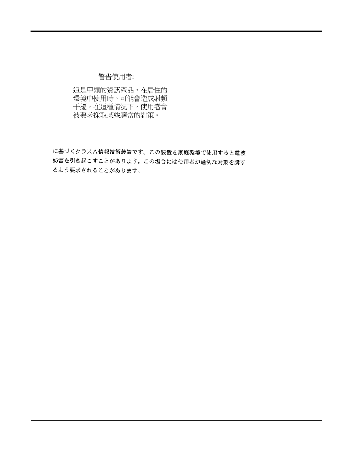
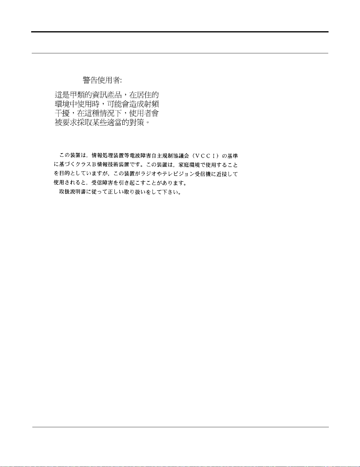
It is the responsibility of the user to carefully read and understand the User Manual statements for Class A
Equipment and Class B Equipment that appear on page iii and page iv, respectively.
Contact Information
You can request Quantum publications from your Quantum Sales Representative or order them directly from
Quantum.
Telephone numbers and street addresses change frequently; for the latest, up-to-date contact information, visit:
www.quantum.com
Te lephone numbers, street addresses, time zones, and other pertinent facts are listed in the Support section of the
web site.
ii July 2004 81-81276-01 Rev A01
Page 3

DLT1/VS80 SCSI Interface Guide
Revision History
The following table lists all revisions made to this document in chronological order.
Document Release Date Summary of Changes
Rev 01 10/06/2000 Initial Release
Rev 02 7/27/2001 Cover Sheet Updates
81-81276-01 Rev
A01
7/26/2004 Converted to FrameMaker and Quantum Style Guide. Released
Per C0O9834.
User Manual Statements for Class A Equipment (Internal Tape
System)
This is a Class A product. This equipment has been tested and found to comply with the limits for a Class A
digital device, pursuant to part 15 of the FCC Rules. These limits are designed to provide reasonable protection
against harmful interference when the equipment is operated in a commercial environment. This equipment
generates, uses, and can radiate radio frequency energy and, if not installed and used in accordance with the
instruction manual, may cause harmful interference to radio communications. Operation of this equipment in a
residential area may cause harmful interference in which case the user will be required to correct the interference
at his own expense.
Any modifications to this device—unless expressly approved by the manufacturer—can void the user’s authority
to operate this equipment under Part 15 of the FCC rules.
German Statement
Dieses ist ein Gerät der Funkstörgrenzwertklasse A. In Wohnbereichen können bei Betrieb dieses Gerätes
Rundfunkstörungen auftreten, in welchen Fällen der Benutzer für entsprechende Gegenmaßnahmen
verantwortlich ist.
Canadian Notice (Avis Canadien)
This Class A digital apparatus complies with Canadian ICES-003.
Cet appareil numérique de la classe A est conforme à la norme NMB-003 du Canada.
French Statement
Ceci est un produit de Classe A. Dans un environnement domestique, ce produit risque de créer des interférences
radioélectriques, il appartiendra alors à l'utilisateur de prendre les mesures spécifiques appropriées.
81-81276-01 Re v A01 July 2004 iii
Page 4
DLT1/VS80 SCSI Interface Guide
Taiwan Statement
Japanese Notice
User Manual Statements for Class B Equipment (External Tape
System)
This equipment has been tested and found to comply with the limits for a Class B digital device, pursuant to Part
15 of the FCC rules. These limits are designed to provide reasonable protection against harmful interference in a
residential installation. Any modifications to this device—unless expressly approved by the manufacturer—can
void the user’s authority to operate this equipment under part 15 of the FCC rules. Operation is subject to the
following two conditions: (1) This device may not cause harmful interference, and (2) this device must accept
any interference that may cause undesirable operation.
This equipment generates, uses, and can radiate radio frequency energy and, if not installed and used in
accordance with the instructions, may cause harmful interference to radio communications. However, there is no
guarantee that interference will not occur in a particular installation. If this equipment does cause harmful
interference to radio or television reception, which can be determined by turning the equipment off and on, the
user is encouraged to try to correct the interference by one or more of the following measures:
• Reorient or relocate the receiving antenna.
• Increase the separation between the equipment and receiver.
• Connect the equipment into an outlet on a circuit different from that to which the receiver is connected.
• Consult the dealer or an experienced radio or TV technician for help.
Canadian Notice
This Class B digital apparatus complies with Canadian ICES-003.
Cet appareil numérique de la classe B est conforme à la norme NMB-003 du Canada.
iv July 2004 81-81276-01 Rev A01
Page 5
DLT1/VS80 SCSI Interface Guide
Taiwan Statement
Japanese Notice
81-81276-01 Re v A01 July 2004 v
Page 6

DLT1/VS80 SCSI Interface Guide
Notes
vi July 2004 81-81276-01 Rev A01
Page 7

Table of Contents
1
Introduction . . . . . . . . . . . . . . . . . . . . . . . . . . . . . . . . . . . . . . . 1-1
Purpose and Scope. . . . . . . . . . . . . . . . . . . . . . . . . . . . . . . . . . . . . . . . . . . . . . . . . . . . . . . . . . . . . . . 1-1
Audience . . . . . . . . . . . . . . . . . . . . . . . . . . . . . . . . . . . . . . . . . . . . . . . . . . . . . . . . . . . . . . . . . . . . . . 1-1
Related Documents . . . . . . . . . . . . . . . . . . . . . . . . . . . . . . . . . . . . . . . . . . . . . . . . . . . . . . . . . . . . . . 1-2
Structure of this Manual . . . . . . . . . . . . . . . . . . . . . . . . . . . . . . . . . . . . . . . . . . . . . . . . . . . . . . . . . . 1 -2
Conventions Used In This Manual . . . . . . . . . . . . . . . . . . . . . . . . . . . . . . . . . . . . . . . . . . . . . . . . . . 1-2
2
General SCSI Bus Operation . . . . . . . . . . . . . . . . . . . . . . . . . . . 2-1
Data Transfer. . . . . . . . . . . . . . . . . . . . . . . . . . . . . . . . . . . . . . . . . . . . . . . . . . . . . . . . . . . . . . . . . . . 2-1
Initiator/Target Operation . . . . . . . . . . . . . . . . . . . . . . . . . . . . . . . . . . . . . . . . . . . . . . . . . . . . . . . . . 2-1
SCSI IDs and Logical Unit Numbers . . . . . . . . . . . . . . . . . . . . . . . . . . . . . . . . . . . . . . . . . . . . . . . . 2-2
UNIT ATTENTION Condition . . . . . . . . . . . . . . . . . . . . . . . . . . . . . . . . . . . . . . . . . . . . . . . . . . . . . 2-2
Behavior Around Power-On and SCSI BUS RESET . . . . . . . . . . . . . . . . . . . . . . . . . . . . . . . . . . . . 2-3
Data Cache and Medium Write Interaction. . . . . . . . . . . . . . . . . . . . . . . . . . . . . . . . . . . . . . . . . . . . 2-3
Other SCSI Functionality . . . . . . . . . . . . . . . . . . . . . . . . . . . . . . . . . . . . . . . . . . . . . . . . . . . . . . . . . 2-4
Bus Phases. . . . . . . . . . . . . . . . . . . . . . . . . . . . . . . . . . . . . . . . . . . . . . . . . . . . . . . . . . . . . . . . . . . . . 2-4
ATTENTION Signal Response. . . . . . . . . . . . . . . . . . . . . . . . . . . . . . . . . . . . . . . . . . . . . . . . . . 2-4
STATUS Phase . . . . . . . . . . . . . . . . . . . . . . . . . . . . . . . . . . . . . . . . . . . . . . . . . . . . . . . . . . . . . . 2-5
BUS FREE Phase . . . . . . . . . . . . . . . . . . . . . . . . . . . . . . . . . . . . . . . . . . . . . . . . . . . . . . . . . . . . 2-6
Bus Parity Errors. . . . . . . . . . . . . . . . . . . . . . . . . . . . . . . . . . . . . . . . . . . . . . . . . . . . . . . . . . . . . . . . 2 -6
3
SCSI Messages. . . . . . . . . . . . . . . . . . . . . . . . . . . . . . . . . . . . . . 3-1
SCSI Message System . . . . . . . . . . . . . . . . . . . . . . . . . . . . . . . . . . . . . . . . . . . . . . . . . . . . . . . . . . . . 3-1
Supported SCSI Messages. . . . . . . . . . . . . . . . . . . . . . . . . . . . . . . . . . . . . . . . . . . . . . . . . . . . . . . . . 3-2
ABORT (06h) . . . . . . . . . . . . . . . . . . . . . . . . . . . . . . . . . . . . . . . . . . . . . . . . . . . . . . . . . . . . . . . 3-2
BUS DEVICE RESET (0Ch) . . . . . . . . . . . . . . . . . . . . . . . . . . . . . . . . . . . . . . . . . . . . . . . . . . . 3-3
COMMAND COMPLETE (00h) . . . . . . . . . . . . . . . . . . . . . . . . . . . . . . . . . . . . . . . . . . . . . . . . 3-3
81-81276-01 Rev A01 July 2004 vii
Page 8

Table of Cont ents
4
SCSI Commands . . . . . . . . . . . . . . . . . . . . . . . . . . . . . . . . . . . . 4-1
DISCONNECT (04h) . . . . . . . . . . . . . . . . . . . . . . . . . . . . . . . . . . . . . . . . . . . . . . . . . . . . . . . . . 3 -3
EXTENDED MESSAGE (01h) . . . . . . . . . . . . . . . . . . . . . . . . . . . . . . . . . . . . . . . . . . . . . . . . . 3-4
IDENTIFY (80h–FFh) . . . . . . . . . . . . . . . . . . . . . . . . . . . . . . . . . . . . . . . . . . . . . . . . . . . . . . . . 3-5
IGNORE WIDE RESIDUE (23h). . . . . . . . . . . . . . . . . . . . . . . . . . . . . . . . . . . . . . . . . . . . . . . . 3-5
INITIATOR DETECTED ERROR (05h) . . . . . . . . . . . . . . . . . . . . . . . . . . . . . . . . . . . . . . . . . . 3-6
LINKED COMMAND COMPLETE (0Ah) . . . . . . . . . . . . . . . . . . . . . . . . . . . . . . . . . . . . . . . . 3-6
LINKED COMMAND COMPLETE, with flag (0Bh). . . . . . . . . . . . . . . . . . . . . . . . . . . . . . . . 3 -6
MESSAGE PARITY ERROR (09h). . . . . . . . . . . . . . . . . . . . . . . . . . . . . . . . . . . . . . . . . . . . . . 3-6
MESSAGE REJECT (07h). . . . . . . . . . . . . . . . . . . . . . . . . . . . . . . . . . . . . . . . . . . . . . . . . . . . . 3-7
NO–OPERATION (NO–OP, 08h). . . . . . . . . . . . . . . . . . . . . . . . . . . . . . . . . . . . . . . . . . . . . . . . 3-7
RESTORE POINTERS (03h). . . . . . . . . . . . . . . . . . . . . . . . . . . . . . . . . . . . . . . . . . . . . . . . . . . 3-7
SAVE DATA POINTER (02h) . . . . . . . . . . . . . . . . . . . . . . . . . . . . . . . . . . . . . . . . . . . . . . . . . . 3-8
SYNCHRONOUS DATA TRANSFER REQUEST (SDTR). . . . . . . . . . . . . . . . . . . . . . . . . . . 3-8
WIDE DATA TRANSFER REQUEST (WDTR). . . . . . . . . . . . . . . . . . . . . . . . . . . . . . . . . . . . 3-8
Control Byte — Flag and Link Bits. . . . . . . . . . . . . . . . . . . . . . . . . . . . . . . . . . . . . . . . . . . . . . . . . . 4-1
Summary of Supported Sequential-Access Tape Drive Commands . . . . . . . . . . . . . . . . . . . . . . . . . 4-2
ERASE (19h). . . . . . . . . . . . . . . . . . . . . . . . . . . . . . . . . . . . . . . . . . . . . . . . . . . . . . . . . . . . . . . . . . . 4-3
INQUIRY (12h). . . . . . . . . . . . . . . . . . . . . . . . . . . . . . . . . . . . . . . . . . . . . . . . . . . . . . . . . . . . . . . . . 4-4
Tape Drive Inquiry Response . . . . . . . . . . . . . . . . . . . . . . . . . . . . . . . . . . . . . . . . . . . . . . . . . . . 4-5
Vendor Unique Inquiry Data. . . . . . . . . . . . . . . . . . . . . . . . . . . . . . . . . . . . . . . . . . . . . . . . . . . . 4-8
Vendor Unique Inquiry Bytes . . . . . . . . . . . . . . . . . . . . . . . . . . . . . . . . . . . . . . . . . . . . . . . . . . . 4-9
Vital Product Data Pages. . . . . . . . . . . . . . . . . . . . . . . . . . . . . . . . . . . . . . . . . . . . . . . . . . . . . . 4-10
Supported Vital Product Data Page (00h) . . . . . . . . . . . . . . . . . . . . . . . . . . . . . . . . . . . . . 4-10
Unit Serial Number Page (80h) . . . . . . . . . . . . . . . . . . . . . . . . . . . . . . . . . . . . . . . . . . . . . 4-10
Firmware Build Information Page (C0h) . . . . . . . . . . . . . . . . . . . . . . . . . . . . . . . . . . . . . . 4-11
Media Loader Inquiry Response . . . . . . . . . . . . . . . . . . . . . . . . . . . . . . . . . . . . . . . . . . . . 4-11
Subsystem Components Revision Page (C1h). . . . . . . . . . . . . . . . . . . . . . . . . . . . . . . . . . 4-12
LOAD/UNLOAD (1Bh) . . . . . . . . . . . . . . . . . . . . . . . . . . . . . . . . . . . . . . . . . . . . . . . . . . . . . . . . . 4-13
LOCATE (2Bh) . . . . . . . . . . . . . . . . . . . . . . . . . . . . . . . . . . . . . . . . . . . . . . . . . . . . . . . . . . . . . . . . 4-15
LOG SELECT (4Ch). . . . . . . . . . . . . . . . . . . . . . . . . . . . . . . . . . . . . . . . . . . . . . . . . . . . . . . . . . . . 4-16
Error Detection Summary in LOG SELECT CDB. . . . . . . . . . . . . . . . . . . . . . . . . . . . . . . . . . 4-18
Operation of LOG SELECT . . . . . . . . . . . . . . . . . . . . . . . . . . . . . . . . . . . . . . . . . . . . . . . . . . . 4-18
LOG SELECT Page Format . . . . . . . . . . . . . . . . . . . . . . . . . . . . . . . . . . . . . . . . . . . . . . . . . . . 4-19
Error Detection Summary in LOG SELECT Pages . . . . . . . . . . . . . . . . . . . . . . . . . . . . . . . . . 4-22
LOG SENSE (4Dh). . . . . . . . . . . . . . . . . . . . . . . . . . . . . . . . . . . . . . . . . . . . . . . . . . . . . . . . . . . . . 4-23
Error Detection Summary in LOG SENSE CDB . . . . . . . . . . . . . . . . . . . . . . . . . . . . . . . . . . . 4-25
Supported Pages Log Page (Page 00h). . . . . . . . . . . . . . . . . . . . . . . . . . . . . . . . . . . . . . . . . . . 4-26
viii July 2004 81-81276-01 Rev A01
Page 9

DLT1/VS80 SCSI Interface Guide
Read/Write Error LOG SENSE Page (Pages 02h and 03h) . . . . . . . . . . . . . . . . . . . . . . . . . . . 4-27
Last n Error Events Page (07h). . . . . . . . . . . . . . . . . . . . . . . . . . . . . . . . . . . . . . . . . . . . . . . . . 4-31
TapeAlert Parameters Page (2Eh). . . . . . . . . . . . . . . . . . . . . . . . . . . . . . . . . . . . . . . . . . . . . . . 4-33
Read/Write Compression Ratio Page (32h) . . . . . . . . . . . . . . . . . . . . . . . . . . . . . . . . . . . . . . . 4-35
Parameter Codes. . . . . . . . . . . . . . . . . . . . . . . . . . . . . . . . . . . . . . . . . . . . . . . . . . . . . . . . . 4-36
Parameter Block: Codes 00h and 01h . . . . . . . . . . . . . . . . . . . . . . . . . . . . . . . . . . . . . . . . 4-36
Parameter Block: Parameter Codes 02h through 09h . . . . . . . . . . . . . . . . . . . . . . . . . . . . 4-38
Device We llness LOG SENSE Page (33h). . . . . . . . . . . . . . . . . . . . . . . . . . . . . . . . . . . . . . . . 4-39
Device Status Log Page (3Eh) . . . . . . . . . . . . . . . . . . . . . . . . . . . . . . . . . . . . . . . . . . . . . . . . . 4-42
MODE SELECT (15h/55h). . . . . . . . . . . . . . . . . . . . . . . . . . . . . . . . . . . . . . . . . . . . . . . . . . . . . . . 4-44
MODE SELECT Parameter List. . . . . . . . . . . . . . . . . . . . . . . . . . . . . . . . . . . . . . . . . . . . . . . . 4-46
MODE SELECT Pages. . . . . . . . . . . . . . . . . . . . . . . . . . . . . . . . . . . . . . . . . . . . . . . . . . . . . . . 4-48
Read/Write Error Recovery Page (01h) . . . . . . . . . . . . . . . . . . . . . . . . . . . . . . . . . . . . . . . . . . 4-49
Disconnect/Reconnect Page (02h) . . . . . . . . . . . . . . . . . . . . . . . . . . . . . . . . . . . . . . . . . . . . . . 4-51
Device Configuration Page (10h) . . . . . . . . . . . . . . . . . . . . . . . . . . . . . . . . . . . . . . . . . . . . . . . 4-53
Control Mode Page (0Ah). . . . . . . . . . . . . . . . . . . . . . . . . . . . . . . . . . . . . . . . . . . . . . . . . . . . . 4-55
Data Compression Page (0Fh) . . . . . . . . . . . . . . . . . . . . . . . . . . . . . . . . . . . . . . . . . . . . . . . . . 4-56
Medium Partition Page (11h) . . . . . . . . . . . . . . . . . . . . . . . . . . . . . . . . . . . . . . . . . . . . . . . . . . 4-58
TapeAlert Page (1Ch) . . . . . . . . . . . . . . . . . . . . . . . . . . . . . . . . . . . . . . . . . . . . . . . . . . . . . . . . 4-60
EEPROM Vendor Unique Page (3Eh) . . . . . . . . . . . . . . . . . . . . . . . . . . . . . . . . . . . . . . . . . . . 4-61
MODE SELECT Changeable Parameters. . . . . . . . . . . . . . . . . . . . . . . . . . . . . . . . . . . . . . . . . 4-67
MODE SENSE (1Ah/5Ah) . . . . . . . . . . . . . . . . . . . . . . . . . . . . . . . . . . . . . . . . . . . . . . . . . . . . . . . 4-68
MODE SENSE Parameter List. . . . . . . . . . . . . . . . . . . . . . . . . . . . . . . . . . . . . . . . . . . . . . . . . 4-69
MODE SENSE Pages . . . . . . . . . . . . . . . . . . . . . . . . . . . . . . . . . . . . . . . . . . . . . . . . . . . . . . . . 4-73
Read/Write Error Recovery Page (01h) . . . . . . . . . . . . . . . . . . . . . . . . . . . . . . . . . . . . . . . . . . 4-74
Disconnect/Reconnect Page (02h) . . . . . . . . . . . . . . . . . . . . . . . . . . . . . . . . . . . . . . . . . . . . . . 4-75
Control Mode Page (0Ah). . . . . . . . . . . . . . . . . . . . . . . . . . . . . . . . . . . . . . . . . . . . . . . . . . . . . 4-77
Data Compression Page (0Fh) . . . . . . . . . . . . . . . . . . . . . . . . . . . . . . . . . . . . . . . . . . . . . . . . . 4-78
Device Configuration Page (10h) . . . . . . . . . . . . . . . . . . . . . . . . . . . . . . . . . . . . . . . . . . . . . . . 4-80
Medium Partition Page (11h) . . . . . . . . . . . . . . . . . . . . . . . . . . . . . . . . . . . . . . . . . . . . . . . . . . 4-82
TapeAlert Page (1Ch) . . . . . . . . . . . . . . . . . . . . . . . . . . . . . . . . . . . . . . . . . . . . . . . . . . . . . . . . 4-83
EEPROM Vendor Unique Page (3Eh) . . . . . . . . . . . . . . . . . . . . . . . . . . . . . . . . . . . . . . . . . . . 4-84
PREVENT/ALLOW MEDIUM REMOVAL (1Eh) . . . . . . . . . . . . . . . . . . . . . . . . . . . . . . . . . . . . 4-85
READ (08h). . . . . . . . . . . . . . . . . . . . . . . . . . . . . . . . . . . . . . . . . . . . . . . . . . . . . . . . . . . . . . . . . . . 4-86
Filemark and End-of-Data Handling. . . . . . . . . . . . . . . . . . . . . . . . . . . . . . . . . . . . . . . . . . . . . 4-87
End-of-Medium/Partition Handling . . . . . . . . . . . . . . . . . . . . . . . . . . . . . . . . . . . . . . . . . . . . . 4-87
READ BLOCK LIMITS (05h) . . . . . . . . . . . . . . . . . . . . . . . . . . . . . . . . . . . . . . . . . . . . . . . . . . . . 4-88
81-81276-01 Rev A01 July 2004 ix
Page 10

Table of Cont ents
READ BUFFER (3Ch) . . . . . . . . . . . . . . . . . . . . . . . . . . . . . . . . . . . . . . . . . . . . . . . . . . . . . . . . . . 4-89
READ POSITION (34h) . . . . . . . . . . . . . . . . . . . . . . . . . . . . . . . . . . . . . . . . . . . . . . . . . . . . . . . . . 4-92
RECEIVE DIAGNOSTICS RESULTS (1Ch) . . . . . . . . . . . . . . . . . . . . . . . . . . . . . . . . . . . . . . . . 4-94
RELEASE UNIT (17h) . . . . . . . . . . . . . . . . . . . . . . . . . . . . . . . . . . . . . . . . . . . . . . . . . . . . . . . . . . 4-95
REQUEST SENSE (03h) . . . . . . . . . . . . . . . . . . . . . . . . . . . . . . . . . . . . . . . . . . . . . . . . . . . . . . . . 4-96
RESERVE UNIT (16h) . . . . . . . . . . . . . . . . . . . . . . . . . . . . . . . . . . . . . . . . . . . . . . . . . . . . . . . . . 4-108
REWIND (01h) . . . . . . . . . . . . . . . . . . . . . . . . . . . . . . . . . . . . . . . . . . . . . . . . . . . . . . . . . . . . . . . 4-110
SEND DIAGNOSTIC (1Dh). . . . . . . . . . . . . . . . . . . . . . . . . . . . . . . . . . . . . . . . . . . . . . . . . . . . . 4-111
SPACE (11h) . . . . . . . . . . . . . . . . . . . . . . . . . . . . . . . . . . . . . . . . . . . . . . . . . . . . . . . . . . . . . . . . . 4-115
TEST UNIT READY (00h). . . . . . . . . . . . . . . . . . . . . . . . . . . . . . . . . . . . . . . . . . . . . . . . . . . . . . 4-116
VERIFY (13h). . . . . . . . . . . . . . . . . . . . . . . . . . . . . . . . . . . . . . . . . . . . . . . . . . . . . . . . . . . . . . . . 4 -117
WRITE (0Ah) . . . . . . . . . . . . . . . . . . . . . . . . . . . . . . . . . . . . . . . . . . . . . . . . . . . . . . . . . . . . . . . . 4-118
WRITE BUFFER (3Bh) . . . . . . . . . . . . . . . . . . . . . . . . . . . . . . . . . . . . . . . . . . . . . . . . . . . . . . . . 4-121
WRITE FILEMARKS (10h). . . . . . . . . . . . . . . . . . . . . . . . . . . . . . . . . . . . . . . . . . . . . . . . . . . . . 4-123
Combined Header and Data Mode . . . . . . . . . . . . . . . . . . . . . . . . . . . . . . . . . . . . . . . . . . . . . . 4-90
Available Length . . . . . . . . . . . . . . . . . . . . . . . . . . . . . . . . . . . . . . . . . . . . . . . . . . . . . . . . 4-91
Data Mode. . . . . . . . . . . . . . . . . . . . . . . . . . . . . . . . . . . . . . . . . . . . . . . . . . . . . . . . . . . . . . . . . 4-91
Descriptor Mode . . . . . . . . . . . . . . . . . . . . . . . . . . . . . . . . . . . . . . . . . . . . . . . . . . . . . . . . . . . . 4-91
READ POSITION Data Short Format . . . . . . . . . . . . . . . . . . . . . . . . . . . . . . . . . . . . . . . . . . . 4-93
RECEIVE DIAGNOSTIC RESULTS Data . . . . . . . . . . . . . . . . . . . . . . . . . . . . . . . . . . . . . . . 4-95
Sense Information Format. . . . . . . . . . . . . . . . . . . . . . . . . . . . . . . . . . . . . . . . . . . . . . . . . . . . . 4-98
Sense Keys . . . . . . . . . . . . . . . . . . . . . . . . . . . . . . . . . . . . . . . . . . . . . . . . . . . . . . . . . . . . . . . 4 -100
Medium Changer Considerations . . . . . . . . . . . . . . . . . . . . . . . . . . . . . . . . . . . . . . . . . . . . . . 4-109
Header and Data Mode . . . . . . . . . . . . . . . . . . . . . . . . . . . . . . . . . . . . . . . . . . . . . . . . . . . . . . 4-122
Write Data Mode. . . . . . . . . . . . . . . . . . . . . . . . . . . . . . . . . . . . . . . . . . . . . . . . . . . . . . . . . . . 4-122
Download Microcode Mode. . . . . . . . . . . . . . . . . . . . . . . . . . . . . . . . . . . . . . . . . . . . . . . . . . 4-122
Download Microcode and Save Mode . . . . . . . . . . . . . . . . . . . . . . . . . . . . . . . . . . . . . . . . . . 4-123
5
Supported SCSI-2 Medium Changer Device Commands . . . . . 5-1
INITIALIZE ELEMENT STATUS (07h) . . . . . . . . . . . . . . . . . . . . . . . . . . . . . . . . . . . . . . . . . . . . . 5 -2
MODE SENSE/SELECT (1Ah/15h). . . . . . . . . . . . . . . . . . . . . . . . . . . . . . . . . . . . . . . . . . . . . . . . . 5-2
Device Capabilities Page (1Fh). . . . . . . . . . . . . . . . . . . . . . . . . . . . . . . . . . . . . . . . . . . . . . . . . . 5-3
Bit Field Values . . . . . . . . . . . . . . . . . . . . . . . . . . . . . . . . . . . . . . . . . . . . . . . . . . . . . . . . . . 5-3
MOVE MEDIUM (A5h). . . . . . . . . . . . . . . . . . . . . . . . . . . . . . . . . . . . . . . . . . . . . . . . . . . . . . . . . . 5-4
x July 2004 81-81276-01 Rev A01
Page 11

DLT1/VS80 SCSI Interface Guide
READ ELEMENT STATUS (B8h). . . . . . . . . . . . . . . . . . . . . . . . . . . . . . . . . . . . . . . . . . . . . . . . . . 5-4
Element Status Header . . . . . . . . . . . . . . . . . . . . . . . . . . . . . . . . . . . . . . . . . . . . . . . . . . . . . . . . 5-6
Medium Transport Element Status Page. . . . . . . . . . . . . . . . . . . . . . . . . . . . . . . . . . . . . . . . . . . 5-7
Storage Element Status Page. . . . . . . . . . . . . . . . . . . . . . . . . . . . . . . . . . . . . . . . . . . . . . . . . . . . 5-9
Data Transfer Element Status Page. . . . . . . . . . . . . . . . . . . . . . . . . . . . . . . . . . . . . . . . . . . . . . 5-11
Element Address Assignment Page (1Dh) . . . . . . . . . . . . . . . . . . . . . . . . . . . . . . . . . . . . . . . . 5-13
81-81276-01 Rev A01 July 2004 xi
Page 12

Table of Cont ents
Notes
xii July 2004 81-81276-01 Rev A01
Page 13

List of Figures
3
SCSI Messages. . . . . . . . . . . . . . . . . . . . . . . . . . . . . . . . . . . . . . 3-1
Figure 3-1. EXTENDED MESSAGE (01h) Format. . . . . . . . . . . . . . . . . . . . . . . . . . . . . . . . . . . . . 3-4
Figure 3-2. IGNORE WIDE RESIDUE Format (23h) . . . . . . . . . . . . . . . . . . . . . . . . . . . . . . . . . . . 3-5
Figure 3-3. SDTR Extended Message Format. . . . . . . . . . . . . . . . . . . . . . . . . . . . . . . . . . . . . . . . . . 3-8
Figure 3-4. WDTR Message Format. . . . . . . . . . . . . . . . . . . . . . . . . . . . . . . . . . . . . . . . . . . . . . . . . 3-9
4
SCSI Commands . . . . . . . . . . . . . . . . . . . . . . . . . . . . . . . . . . . . 4-1
Figure 4-1. ERASE (19h) Command Descriptor Block — Data Format . . . . . . . . . . . . . . . . . . . . . 4-3
Figure 4-2. INQUIRY (12h) Command Descriptor Block — Data Format . . . . . . . . . . . . . . . . . . . 4-4
Figure 4-3. Standard Inquiry Data Page — Data Format . . . . . . . . . . . . . . . . . . . . . . . . . . . . . . . . . 4-5
Figure 4-4. INQUIRY Vendor Unique Bytes — Data Format . . . . . . . . . . . . . . . . . . . . . . . . . . . . . 4-8
Figure 4-5. Supported Vital Product Data Page — Data Format . . . . . . . . . . . . . . . . . . . . . . . . . . 4-10
Figure 4-6. Unit Serial Number Page — Data Format . . . . . . . . . . . . . . . . . . . . . . . . . . . . . . . . . . 4-10
Figure 4-7. Firmware Build Information Page — Data Format . . . . . . . . . . . . . . . . . . . . . . . . . . . 4-11
Figure 4-8. Subsystem Components Revision Page — Data Format . . . . . . . . . . . . . . . . . . . . . . . 4-12
Figure 4-9. LOAD-UNLOAD (1Bh) Command Descriptor Block — Data Format. . . . . . . . . . . . 4-14
Figure 4-10. LOCATE (2Bh) Command Descriptor Block — Data Format. . . . . . . . . . . . . . . . . . 4-15
Figure 4-11. LOG SELECT (4Ch) Command Descriptor Block — Data Format . . . . . . . . . . . . . 4-16
Figure 4-12. LOG SELECT Log Page Header — Data Format . . . . . . . . . . . . . . . . . . . . . . . . . . . 4-19
Figure 4-13. LOG SELECT Log Page Parameters — Data Format . . . . . . . . . . . . . . . . . . . . . . . . 4-20
Figure 4-14. LOG SENSE (4Dh) Command Descriptor Block — Data Format . . . . . . . . . . . . . . 4-23
Figure 4-15. Supported Pages Log Page 0 — Data Format . . . . . . . . . . . . . . . . . . . . . . . . . . . . . . 4-26
Figure 4-16. Read / Write Error LOG SENSE (Page 2 and 3) Header — Data Format. . . . . . . . . 4-27
Figure 4-17. Rea d / Write Error L OG SEN SE Parameters (P ages 02h and 03h) — D ata Format . 4-28
Figure 4-18. Log Pa rameters for Last n Error Events LOG SENSE Page — Data Format . . . . . . 4-31
Figure 4-19. Read / Write Compression Ratio (32h) Page Header — Data Format . . . . . . . . . . . . 4-35
Figure 4-20. Read / Write Compression Ratio Log Page — Data Format . . . . . . . . . . . . . . . . . . . 4-36
Figure 4-21. Read / Write Bytes Transferred Log Page — Data Format . . . . . . . . . . . . . . . . . . . . 4-38
81-81276-01 R ev A01 July 2004 xi
Page 14

List of Figures
Figure 4-22. Device Wellness (33h) Log Page Header — Data Format. . . . . . . . . . . . . . . . . . . . . 4-40
Figure 4-23. D evi ce Wellness (33h) L og Page Parameters (0000h throu gh 000Fh) — Data
Format . . . . . . . . . . . . . . . . . . . . . . . . . . . . . . . . . . . . . . . . . . . . . . . . . . . . . . . . . . . . . . . . . . . . . . . 4-41
Figure 4-24. Device Status (3Eh) Log Page Header — Data Format . . . . . . . . . . . . . . . . . . . . . . . 4-42
Figure 4-25. D evi ce Status (3Eh) Log Pa ge Parameters (0000h through 0002h) — Data Fo rm at. 4-42
Figure 4-26. D evi ce Status (3Eh) Log Page Parameter Code (0001h) — Dat a Format . . . . . . . . . 4-43
Figure 4-27. MODE SELECT (15h ) 6- Byte Command De scriptor Block — Data Format . . . . . . 4-44
Figure 4-28. MODE SELECT (55h ) 10-Byte Comm and Descriptor Blo ck — Data Format . . . . . 4-45
Figure 4-29. MODE SELECT (6) Parameter List Header — Data Format . . . . . . . . . . . . . . . . . . 4-46
Figure 4-30. MODE SELECT (6) Parameter List Block Descriptor — Data Format . . . . . . . . . . 4-46
Figure 4-31. MODE SELECT Pages — Data Format. . . . . . . . . . . . . . . . . . . . . . . . . . . . . . . . . . . 4-48
Figure 4-32. Read / Write Error Recovery Page — Data Format . . . . . . . . . . . . . . . . . . . . . . . . . . 4-49
Figure 4-33. Disconnect / Reconnect Page — Data Format . . . . . . . . . . . . . . . . . . . . . . . . . . . . . . 4-51
Figure 4-34. Device Configuration Page — Data Format. . . . . . . . . . . . . . . . . . . . . . . . . . . . . . . . 4-53
Figure 4-35. Control Mode Page — Data Format. . . . . . . . . . . . . . . . . . . . . . . . . . . . . . . . . . . . . . 4-55
Figure 4-36. Data Compression Page — Data Format . . . . . . . . . . . . . . . . . . . . . . . . . . . . . . . . . . 4-57
Figure 4-37. Medium Partition Page — Data Format. . . . . . . . . . . . . . . . . . . . . . . . . . . . . . . . . . . 4-58
Figure 4-38. TapeAlert Page — Data Format . . . . . . . . . . . . . . . . . . . . . . . . . . . . . . . . . . . . . . . . . 4-60
Figure 4-39. MODE SELECT EEPROM Vendor Unique Page — Data Format . . . . . . . . . . . . . . 4-61
Figure 4-40. EEPROM Vendor Unique Page — Example 1 . . . . . . . . . . . . . . . . . . . . . . . . . . . . . . 4-65
Figure 4-41. EEPROM Vendor Unique Page — Example 2 . . . . . . . . . . . . . . . . . . . . . . . . . . . . . . 4-66
Figure 4-42. MODE SENSE (1Ah) 6-Byte Command Descriptor Block — Data Format. . . . . . . 4-68
Figure 4-43. MODE SENSE (5A h) 10-Byte Command D escriptor Block — Data Format. . . . . . 4-68
Figure 4-44. MODE SENSE (6) Data Header — Data Format. . . . . . . . . . . . . . . . . . . . . . . . . . . . 4-69
Figure 4-45. MODE SENSE (10) Data Header — Data Format. . . . . . . . . . . . . . . . . . . . . . . . . . . 4-70
Figure 4-46. MODE SENSE (6/10) Block Descriptor — Data Format . . . . . . . . . . . . . . . . . . . . . 4-71
Figure 4-47. MODE SENSE Page Descriptor — Data Format. . . . . . . . . . . . . . . . . . . . . . . . . . . . 4-73
Figure 4-48. Read / Write Error Recovery Page — Data Format . . . . . . . . . . . . . . . . . . . . . . . . . . 4-74
Figure 4-49. Disconnect / Reconnect Page — Data Format . . . . . . . . . . . . . . . . . . . . . . . . . . . . . . 4-76
Figure 4-50. Control Mode Page — Data Format. . . . . . . . . . . . . . . . . . . . . . . . . . . . . . . . . . . . . . 4-77
Figure 4-51. Data Compression Page — Data Format . . . . . . . . . . . . . . . . . . . . . . . . . . . . . . . . . . 4-78
Figure 4-52. Device Configuration Page — Data Format. . . . . . . . . . . . . . . . . . . . . . . . . . . . . . . . 4-80
Figure 4-53. Medium Partition Page — Data Format. . . . . . . . . . . . . . . . . . . . . . . . . . . . . . . . . . . 4-82
Figure 4-54. TapeAlert Page — Data Format . . . . . . . . . . . . . . . . . . . . . . . . . . . . . . . . . . . . . . . . . 4-83
Figure 4-55. MODE SENSE EEPROM Vendor Unique Page — Data Format . . . . . . . . . . . . . . . 4-84
Figure 4-56. PREVENT/ALLOW MED I U M REMOVAL (1Eh) Command De scriptor
Block — Data Format . . . . . . . . . . . . . . . . . . . . . . . . . . . . . . . . . . . . . . . . . . . . . . . . . . . . . . . . . . . 4-85
Figure 4-57. READ (08h) Command Descriptor Block — Data Format . . . . . . . . . . . . . . . . . . . . 4-86
Figure 4-58. READ BLOCK LIMITS (05 h) Command Descriptor Block — Data Format. . . . . . 4-88
Figure 4-59. READ BLOCK LIMITS (05h) — Data Format. . . . . . . . . . . . . . . . . . . . . . . . . . . . . 4-88
xii July 2004 81-81276-01 R ev A01
Page 15

DLT1/VS80 SCSI Interface Guide
Figure 4-60. READ BUFFER (3Ch) Command Descriptor Block — Data Format. . . . . . . . . . . . 4-89
Figure 4-61. RE A D B UFFER Header for Com bined Header and Data Mode — Da ta Format . . . 4-90
Figure 4-62. READ BUFFER Descriptor — Data Format . . . . . . . . . . . . . . . . . . . . . . . . . . . . . . . 4-91
Figure 4-63. READ POSITION (34h) Command Descriptor Block — Data Format . . . . . . . . . . 4-92
Figure 4-64. READ POSITION (Short Format) — Data Format. . . . . . . . . . . . . . . . . . . . . . . . . . 4-93
Figure 4-65. RECEIVE DIAGNOSTICS RESULTS (1Ch) Command Descriptor
Block — Data Format . . . . . . . . . . . . . . . . . . . . . . . . . . . . . . . . . . . . . . . . . . . . . . . . . . . . . . . . . . . 4-94
Figure 4-66. RECEIVE DIAGNOSTICS RESULTS (1Ch) — Data Format . . . . . . . . . . . . . . . . . 4-95
Figure 4-67. RELEASE UNIT (17h) Command Descriptor Block — Data Format . . . . . . . . . . . 4-95
Figure 4-68. REQUEST SENSE (03h) Command Descriptor Block — Data Format. . . . . . . . . . 4-96
Figure 4-69. REQUEST SENSE — Data Format. . . . . . . . . . . . . . . . . . . . . . . . . . . . . . . . . . . . . . 4-98
Figure 4-70. RESERVE UNIT (16h) Command Descriptor Block — Data Format. . . . . . . . . . . 4 -108
Figure 4-71. REWIND (01h) Command Descriptor Block — Data Format. . . . . . . . . . . . . . . . . 4-110
Figure 4-72. SEND DIAGNOSTIC (1Dh) Command Descriptor Block — Data Format . . . . . . 4-111
Figure 4-73. SEND DIAGNOSTIC (1Dh) Parameter List — Data Format . . . . . . . . . . . . . . . . . 4-112
Figure 4-74. SPACE (11h) Command Descriptor Block — Data Format. . . . . . . . . . . . . . . . . . . 4-115
Figure 4-75. TEST UNIT READY (00h) Command Descriptor Block — Data Format . . . . . . . 4-117
Figure 4-76. VERIFY (13h) Command Descriptor Block — Data Format . . . . . . . . . . . . . . . . . 4-117
Figure 4-77. WRITE (0Ah) Command Descriptor Block — Data Format. . . . . . . . . . . . . . . . . . 4 -119
Figure 4-78. WRITE BUFFER (3Bh) Command Descriptor Block — Data Format. . . . . . . . . . 4-121
Figure 4-79. WRITE FILEMA RK S (10h) Command D escriptor Block — Data Format . . . . . . 4 -123
5
Supported SCSI-2 Medium Changer Device Commands . . . . . 5-1
Figure 5-1. INITIALIZE ELEMENT STATUS (07h) — Data Format. . . . . . . . . . . . . . . . . . . . . . . 5-2
Figure 5-2. Device Capabilities Page — Data Format . . . . . . . . . . . . . . . . . . . . . . . . . . . . . . . . . . . 5-3
Figure 5-3. MOVE MEDIUM (A5h) — Data Format . . . . . . . . . . . . . . . . . . . . . . . . . . . . . . . . . . . 5 -4
Figure 5-4. READ ELEMENT STATUS (B8h) Command Descriptor Block— Header Format. . . 5-5
Figure 5-5. Element Status Header — Data Format . . . . . . . . . . . . . . . . . . . . . . . . . . . . . . . . . . . . . 5-6
Figure 5-6. Medium Transport Element Status Header — Data Format. . . . . . . . . . . . . . . . . . . . . . 5-7
Figure 5-7. Medium Transport Element Status Descriptor — Data Format . . . . . . . . . . . . . . . . . . . 5 -8
Figure 5-8. Storage Element Status Header — Data Format. . . . . . . . . . . . . . . . . . . . . . . . . . . . . . . 5 -9
Figure 5-9. Storage Element Status Descriptor — Data Format. . . . . . . . . . . . . . . . . . . . . . . . . . . 5-10
Figure 5-10. Data Transfer Element Status Header — Data Format. . . . . . . . . . . . . . . . . . . . . . . . 5-11
Figure 5-11. Data Transfer Element Status Descriptor — Data Format . . . . . . . . . . . . . . . . . . . . . 5-12
Figure 5-12. Element Address Assignment Page — Data Format . . . . . . . . . . . . . . . . . . . . . . . . . 5-14
81-81276-01 R ev A01 July 2004 xiii
Page 16

List of Figures
Notes
xiv July 2004 81-81276-01 Rev A01
Page 17

List of Tables
1
Introduction . . . . . . . . . . . . . . . . . . . . . . . . . . . . . . . . . . . . . . . 1-1
Table 1-1. Typographical Conventions . . . . . . . . . . . . . . . . . . . . . . . . . . . . . . . . . . . . . . . . . . . . . . . 1-3
2
General SCSI Bus Operation . . . . . . . . . . . . . . . . . . . . . . . . . . . 2-1
Table 2-1. Tape Drive Behavior after a Power-On and SCSI BUS RESET . . . . . . . . . . . . . . . . . . . 2-3
3
SCSI Messages. . . . . . . . . . . . . . . . . . . . . . . . . . . . . . . . . . . . . . 3-1
Table 3-1. Supported SCSI Messages . . . . . . . . . . . . . . . . . . . . . . . . . . . . . . . . . . . . . . . . . . . . . . . . 3 -1
Table 3-2. EXTENDED MESSAGE Codes . . . . . . . . . . . . . . . . . . . . . . . . . . . . . . . . . . . . . . . . . . . 3-4
Table 3-3. Bits in the IDENTIFY Message. . . . . . . . . . . . . . . . . . . . . . . . . . . . . . . . . . . . . . . . . . . . 3-5
4
SCSI Commands . . . . . . . . . . . . . . . . . . . . . . . . . . . . . . . . . . . . 4-1
Table 4-1. Supported SCSI Commands. . . . . . . . . . . . . . . . . . . . . . . . . . . . . . . . . . . . . . . . . . . . . . . 4-2
Table 4-2. ERASE (19h) Command Descriptor Block — Field Descriptions . . . . . . . . . . . . . . . . . 4-3
Table 4-3. INQUIRY (12h) Command Descriptor Block — Field Descriptions . . . . . . . . . . . . . . . 4-4
Table 4-4. Standard Inquiry Data Page — Field Descriptions . . . . . . . . . . . . . . . . . . . . . . . . . . . . . 4-6
Table 4-5. Vendor Unique Inquiry Data — Field Descriptions. . . . . . . . . . . . . . . . . . . . . . . . . . . . . 4-9
Table 4-6. Subsystem Components Revision Page — Field Descriptions . . . . . . . . . . . . . . . . . . . 4-12
Table 4-7. LOAD/UNLOAD (1Bh) Command Descriptor Block — Field Descriptions. . . . . . . . 4-14
Table 4-8. LOCATE (2Bh) Command Descriptor Block — Field Descriptions. . . . . . . . . . . . . . . 4-15
Table 4-9. LOG SELE CT ( 4Ch) Command Descr ip t or Blo ck — Field Descriptions . . . . . . . . . . 4-17
Table 4-10. LOG SELECT DATA OUT — Phase Codes . . . . . . . . . . . . . . . . . . . . . . . . . . . . . . . . 4-18
Table 4-11. LOG SELECT Log Page Header — Field Descriptions . . . . . . . . . . . . . . . . . . . . . . . 4-19
Table 4-12. LOG SELECT Log Page Parameters — Field Descriptions . . . . . . . . . . . . . . . . . . . . 4-20
Table 4-13. Supported Parameter Codes . . . . . . . . . . . . . . . . . . . . . . . . . . . . . . . . . . . . . . . . . . . . . 4-22
Table 4-14. LOG SE N SE (4Dh) Command Descriptor Blo ck — Field Descriptio ns . . . . . . . . . . 4- 23
81-81276-01 Rev A01 July 2004 xv
Page 18

List of Tables
Table 4-15. Read / Write Error LOG SENSE (Page 2 and 3) — Fi eld Description s . . . . . . . . . . . 4-27
Table 4-16. Read / Write Error LOG SENSE Parameters (Pages 02h and 03h) — Field
Descriptions. . . . . . . . . . . . . . . . . . . . . . . . . . . . . . . . . . . . . . . . . . . . . . . . . . . . . . . . . . . . . . . . . . . 4-28
Table 4-17. Log Parameters for Last n Error Events (07h) LOG SENSE Page — Field
Descriptions. . . . . . . . . . . . . . . . . . . . . . . . . . . . . . . . . . . . . . . . . . . . . . . . . . . . . . . . . . . . . . . . . . . 4-31
Table 4-18. TapeAlert LOG SENSE Parameters — Field Descriptions . . . . . . . . . . . . . . . . . . . . . 4-33
Table 4-19. Read / Write Comp ression Ratio (32 h) Page Header — F ie ld D es criptions . . . . . . . . 4-35
Table 4-20. Suppo rted Parameter Codes for the Rea d / Write Compr ession Ratio Page . . . . . . . . 4-36
Table 4-21. Read / Write Comp re ssion Ratio Log Page — Field Descriptions . . . . . . . . . . . . . . . 4-37
Table 4-22. Read / Write Bytes Transferred LOG SENSE Page — Field Descriptions. . . . . . . . . 4-38
Table 4-23. Device Wellness (33h) Log Page Header — Field Descriptions . . . . . . . . . . . . . . . . . 4-40
Table 4-24. Device Wellness (33h) Log Page Parameters — Field Descriptions. . . . . . . . . . . . . . 4-41
Table 4-25. Device Status (3Eh) Log Page Parameter — Field Descriptions. . . . . . . . . . . . . . . . . 4-43
Table 4-26. Dev i ce Stat us (3Eh) Log Page Pa rameter Code (0 001h) — Field Descriptions . . . . . 4- 44
Table 4-27. MOD E SELECT (15h/55 h) C om m and Descriptor Bl ock — Field Descri pt i ons . . . . 4-45
Table 4-28. MODE SELECT (6) Parameter List — Field Descriptions. . . . . . . . . . . . . . . . . . . . . 4-47
Table 4-29. MODE SELECT Pages — Field Descriptions. . . . . . . . . . . . . . . . . . . . . . . . . . . . . . . 4-48
Table 4-30. Read / Write Error Recovery Page (01h) — Field Descriptions . . . . . . . . . . . . . . . . . 4-50
Table 4-31. Disconnect / Reconnect Page (02h) — Field Descriptions . . . . . . . . . . . . . . . . . . . . . 4-51
Table 4-32. Device Configuration Page — Field Descriptions. . . . . . . . . . . . . . . . . . . . . . . . . . . . 4-53
Table 4-33. Control Mode Page — Field Descriptions. . . . . . . . . . . . . . . . . . . . . . . . . . . . . . . . . . 4-55
Table 4-34. Data Compression Page — Field Descriptions . . . . . . . . . . . . . . . . . . . . . . . . . . . . . . 4-57
Table 4-35. Medium Partition Page — Field Descriptions . . . . . . . . . . . . . . . . . . . . . . . . . . . . . . . 4-59
Table 4-36. TapeAlert Page — Field Descriptions . . . . . . . . . . . . . . . . . . . . . . . . . . . . . . . . . . . . . 4-60
Table 4-37. MOD E SELECT EEPROM Vend or Unique Page — P ar am eter Descriptions . . . . . . 4-61
Table 4-38. Changeable Mode Parameters . . . . . . . . . . . . . . . . . . . . . . . . . . . . . . . . . . . . . . . . . . . 4-67
Table 4-39. MODE SENSE (1Ah/5Ah) Com mand Descript or Block — Field Des criptions. . . . . 4-69
Table 4-40. MODE SENSE (6/10) Data Header— Field Descriptions. . . . . . . . . . . . . . . . . . . . . . 4-70
Table 4-41. MODE SENSE (6/10) Block Descriptor — Field Descriptions . . . . . . . . . . . . . . . . . 4-72
Table 4-42. Supported MODE SENSE Block Pages and Page Codes . . . . . . . . . . . . . . . . . . . . . . 4-73
Table 4-43. MODE SENSE Page — Field Descriptions . . . . . . . . . . . . . . . . . . . . . . . . . . . . . . . . . 4-74
Table 4-44. Read / Write Error Recovery Page — Field Descriptions . . . . . . . . . . . . . . . . . . . . . . 4-74
Table 4-45. Disconnect / Reconnect Page — Field Descriptions . . . . . . . . . . . . . . . . . . . . . . . . . . 4-76
Table 4-46. Control Mode Page — Field Descriptions. . . . . . . . . . . . . . . . . . . . . . . . . . . . . . . . . . 4-77
Table 4-47. Data Compression Page — Field Descriptions . . . . . . . . . . . . . . . . . . . . . . . . . . . . . . 4-79
Table 4-48. Device Configuration Page — Field Descriptions. . . . . . . . . . . . . . . . . . . . . . . . . . . . 4-80
Table 4-49. Medium Partition Page — Field Descriptions . . . . . . . . . . . . . . . . . . . . . . . . . . . . . . . 4-82
Table 4-50. TapeAlert Page — Field Descriptions . . . . . . . . . . . . . . . . . . . . . . . . . . . . . . . . . . . . . 4-83
Table 4-51. PREVENT/ALLOW MED IUM REMOVAL (1Eh) Command Descr ip to r
Block — Field Descriptions . . . . . . . . . . . . . . . . . . . . . . . . . . . . . . . . . . . . . . . . . . . . . . . . . . . . . . 4-85
xvi July 2004 81-81276-01 Rev A01
Page 19

DLT1/VS80 SCSI Interface Guide
Table 4-52. READ (08h) Command Descriptor Block — Field Descriptions . . . . . . . . . . . . . . . . 4-86
Table 4-53. READ B LO C K LIMITS (05h) Command Descripto r Block — Field Descrip t io ns . . 4-89
Table 4-54. READ B U FFER (3Ch) Command Descriptor Block — Field Descrip tions. . . . . . . . 4-90
Table 4-55. READ PO SI TI O N (34h) Command De scriptor Block — Fie ld D es criptions. . . . . . . 4-92
Table 4-56. READ POSITION (Short Format) — Field Descriptions . . . . . . . . . . . . . . . . . . . . . . 4-93
Table 4-57. RELEA SE UNIT (17h) Com m and Descriptor Blo ck — Field Descript ions. . . . . . . . 4-96
Table 4-58. REQU EST SENSE Comm and Descriptor Bl ock — Field Descri pt i ons . . . . . . . . . . . 4-97
Table 4-59. REQUEST SENSE Data — Field Descriptions. . . . . . . . . . . . . . . . . . . . . . . . . . . . . . 4-99
Table 4-60. Supported Sense Keys That Accompany REQUEST SENSE Data. . . . . . . . . . . . . . 4-100
Table 4-61. Support ed SK, ASC, and ASCQ ( H ex) in Response to the REQ UEST SENSE
Command. . . . . . . . . . . . . . . . . . . . . . . . . . . . . . . . . . . . . . . . . . . . . . . . . . . . . . . . . . . . . . . . . . . . 4-101
Table 4-62. RESERVE UNIT (16h) Command Descriptor Block — Field Descrip tions. . . . . . . 4-109
Table 4-63. REWIND (01h) Command Descriptor Block — Field Descriptions . . . . . . . . . . . . . 4-110
Table 4-64. Parameters for SEND DIAGNOSTIC . . . . . . . . . . . . . . . . . . . . . . . . . . . . . . . . . . . . 4-112
Table 4-65. Definition of Pattern Numbers for the SEND DIAGNOSTIC Command. . . . . . . . . 4-113
Table 4-66. Sense Keys Used with SEND DIAGNOSTIC (1Dh). . . . . . . . . . . . . . . . . . . . . . . . . 4-114
Table 4-67. Additional Sense Codes for Reporting Test Results. . . . . . . . . . . . . . . . . . . . . . . . . . 4-114
Table 4-68. SPACE (11h) Command Descriptor Block — Field Descriptions. . . . . . . . . . . . . . . 4-115
Table 4-69. VERIFY (13h) Command Descriptor Block — Field Descriptions . . . . . . . . . . . . . 4-117
Table 4-70. WRITE (0Ah) Command Descriptor Block — Field Descriptions . . . . . . . . . . . . . . 4-119
Table 4-71. WRITE BU FFER (3Bh) Command D es cr ip t or Blo ck — Fi el d D es cr i pt io ns . . . . . . 4-121
Table 4-72. WRIT E FI LEMARKS (10h ) Command Descrip to r Block — Field Descri pt io ns . . 4-124
5
Supported SCSI-2 Medium Changer Device Commands . . . . . 5-1
Table 5-1. SCSI-2 Medium Changer Commands . . . . . . . . . . . . . . . . . . . . . . . . . . . . . . . . . . . . . . . 5-1
Table 5-2. Element Type Code Definitions . . . . . . . . . . . . . . . . . . . . . . . . . . . . . . . . . . . . . . . . . . . . 5-5
Table 5-3. Data Transfe r Elem ent Status Header and Descriptor — Field Descrip tions . . . . . . . . 5-12
Table 5-4. Medium Changer Element Addresses . . . . . . . . . . . . . . . . . . . . . . . . . . . . . . . . . . . . . . 5-14
81-81276-01 Rev A01 July 2004 xvii
Page 20

List of Tables
Notes
xviii July 2004 81-81276-01 Rev A01
Page 21

CHA PTER 1
1.1 Purpose and Scope
This manual provides a detailed explana tio n of the Small Comp uter S ystem In te rface (SCSI) Protocol
features the Quantum VS80 tape drive implements. This manual does not replace the full ANSI SCSI
specificati on, messages, options, and co m mand code spec if i cations; instead, it describes the
commands , messages, and options this tape dr ive supports. It a ls o describes the tape drive’s error
recovery procedures.
NOTE: From this point forward, we may refer to the Quantum VS80 tape drive
simply as the “tape drive.”
Chapter 1
Introduction
1.2 Audience
Quantum provides this docum ent to softwar e and firmware engineers and technicians wh o support
Quantum VS80 tape drives . It also serves sof t w are and firmwar e engineers and t echnicians wh o
integrate Quantum VS80 tape drives into aut omate d sy ste ms su ch as tape drive libraries.
81-81276-01 R ev A01 July 2004 1-1
Page 22

Chapter 1: Introduction
1.3 Related Documents
• DLT VS80 Installation and Operations Guide (001596-01)
• Current standards documents availabl e fr om w ww.t10.org
SCSI Architecture Model (SAM)
SCSI Primary Comm ands (SPC)
SCSI Parallel Interface (SPI)
SCSI Stream Commands (SSC)
1.4 Structure of this Manual
Chapter 1, “Introduction,” is the chapter you are currently rea di ng.
Chapter 2, “General SCSI Bus Opera tion,” describes tape drive responses to a variety of situations that
occur on the SCSI bus; for example , po w er-on, bus phases, data transfer, and so forth .
Chapter 3, “SCSI Messages,” describes the SCSI message system and lists the messages supported by
the tap e d rive.
Chapter 4, “SCSI Commands,” lists the commands the tape drive suppor ts and defines each command .
Chapter 5, “ Supported SCSI- 2 Medium Changer D evice Commands,” lists the commands unique to
the medium ch anger that the tape drive support s . I t al s o defines each supported command.
1.5 Conventions Used In This Manual
This manual uses the following conventions:
NOTE: Notes provide supp le m ental informati on.
1-2 July 2004 81-81276-01 Rev A01
Page 23

DLT1/VS80 SCSI Interface Guide
TECH TIP: Tech Tips provide information that helps you comple te a procedure or
avoid additional steps.
C
AUTION Cautions provide information yo u must know to avoid
damaging the tape drive or losing data.
ARNING! Warnings provide information yo u must know to avoid
W
personal injury.
Table 1-1. Typographical Conventions
Element Convention Example
Commands Uppercase (unless case-
sensitive)
Hexadecimal Notation Number followed by
lowercase h
Binary Notation Number followed by
lowercase b
Decimal Notation Number without suffix 512
Acronyms Uppercase POST
Abbreviations Lowercase, except where
standard usage requires
uppercase
TEST UNIT READY
25h
101b
Mb (megabits)
MB (megabytes)
81-81276-01 R ev A01 July 2004 1-3
Page 24

Chapter 1: Introduction
Notes
1-4 July 2004 81-81276-01 Rev A01
Page 25

2.1 Data Transfer
The tape drive supports both narr ow and wide, asynchronous and sy nchronous data transfers. The
product is conf ig ured as a Low-Voltage Differential (LVD) or Single-Ended (SE) tape drive. The tape
drive generates p arity (ODD) d urin g all i nformati on tr ansfer phases where t he tape dr ive tr ansfer s dat a
onto the SCSI bus. The tape drive also checks parity during all info rmation transfer phases where the
tape drive receives data from the SCSI bus.
The tape drive supports even block sizes of 2 bytes to (16 MB – 2) bytes.
CHA PTER 2
Chapter 2General SCSI Bus Operation
Disconnects from the SCSI bus occur at regular intervals during a data transfer. This allows other tape
drives to acces s t he bus. The Disconnect–Reconn ect Mode Parameters page configures SCSI bus
disconnects.
2.2 Initiator/Target Operation
The tape drive doe s not act as an initiator on t he SCSI bus. Therefor e, th e tape drive does not perform
any of the follow ing tasks:
• Genera t e u nsolic ited inte rrupts to the host
• Initiate its own SCSI commands
• Assert a bus reset.
81-81276-01 R ev A01 July 2004 2-1
Page 26

Chapter 2: General SCSI Bus Operation
2.3 SCSI IDs and Logical Unit Numbers
The tape drive has one logical unit num ber (LUN), which is always LUN 0.
The tape drive treats uns upported LUNs a s follo ws: If the LUN specif ied in t he IDENTIFY message is
invalid, the tap e dr ive accepts the Co m m and Descriptor Block (CDB). The next action is one of the
follow ing three cases:
• If the command is INQUIRY, the target retur ns the INQUIRY data with the peripheral qualifier set
to 011, indicating that the ta rget does not support the LUN in question.
• If the command is REQUEST SENSE, the target returns sense data. The sense key is ILLEGAL
REQUEST, with an Additional Sense Code of INVALID Logical Unit Number.
• For any other command, the tar get terminate s the command with CHECK CONDITION status an d
generates the Sense Data described in item 2.
2.4 UNIT ATTENTION Condition
The tape drive implements Queued Unit Attentions which are maintained separately for each valid
LUN for each Initiator. The host compute r cr eates Unit At te nt io ns under the foll owing conditio ns:
• Power-on Reset
• BUS Reset
• Bus Drive Reset message
• Asynchronous m edi a change
• Mode Parameters changed by another initia to r
• Firmware up dat e completed.
T wo queued Unit Attentions are not unusual. For example, powering up a tape drive and loading a data
cartridge create Power Up and Not-ready to Ready Transition Unit Attentions. Since there are a limited
number of Unit Attention buffers, if an initiator does not clear Unit Attentions queued for it, at some
point the tape drive stops generating new Unit Attentions for that I–L combination. However, existing
Unit Attentions remain queued.
A LOAD command does not generate a Unit Attention for the initiator that issued the command since
the transition to Ready is a synchronous event.
2-2 July 2004 81-81276-01 Rev A01
Page 27

DLT1/VS80 SCSI Interface Guide
2.5 Behavior Around Power-On and SCSI BUS RESET
In the following situations, the tape drive generates these responses:
Table 2-1. Tape Drive Behavior after a Po w er -On and SCSI BUS RESET
Situation Tape Drive Response
Tape drive power off All tape drive SCSI lines go to high impedance.
Tape drive power on The tape drive does not generate any spurious signals on
the SCSI bus
Within 5 seconds of power on and within 250
milliseconds (typically under 4 ms) after a BUS
RESET
The tape drive recognizes multiple bus resets in succession and bus resets of arbitrarily long duration.
It recovers within the time limits specified above following the last bus reset.
The tape drive responds to SCSI bus selections and
returns appropriate, normal responses. The tape drive
returns medium motion commands with CHECK
CONDITION status, Sense Key Not Ready, until the
media is ready.
The tape drive implements the Hard BUS RESET option.
The tape drive rewinds the medium to BOP (Beginning
of Partition, i.e. Beginning of Medium).
2.6 Data Cache and Medium Write Interaction
The tape drive contains a data cache that buffers blocks (records) until writing them. This section
defines specific times that the tape drive writes blocks to medium. A MODE SELECT parameter
allows disab ling the data cache (unbuffered mode). In this mo de, every WRITE com mand cause s t he
tape drive to write data to the data cartridge before returning the STATUS byte and the COMMAND
COMPLETE messages to the host.
NOTE: We do not recommend unbuffere d m o de because it pr oduces poor
performance.
81-81276-01 R ev A01 July 2004 2-3
Page 28

Chapter 2: General SCSI Bus Operation
The tape drive w ri t es ( fl ushes) the write data cache to the dat a cartridge under the following
circumstances:
• An initiator issues one or more WRITE FILEMARKS commands without intervening medium
motion commands.
• An initiator issues a WRITE 0 FILEMARKS command.
• The tape drive automatically writes data in the cache longer than specified by the value of the
Mode Parameter “Write Delay Time” to the data cartridge.
• The tape drive receives a non-write type medium access command; for example, SPACE, READ,
UNLOAD, REWIND, and so forth.
2.7 Other SCSI Functionality
The tape drive supports these addition al func tions:
• Linked commands
• Untagged queuing.
2.8 Bus Phases
The tape drive conforms to the bus state transition table shown in the SCSI-2 standard, “Phase
Sequences.” The informatio n in the follo win g se ct ions also applies.
2.8.1 ATTENTION Signal Response
The tape drive res ponds to an ATN condition at le ast at every phase tr ansition, as lon g as the initiator
sets the ATN bit before the target abandons the REQ for the last byte of the previous phase. Ordinarily
the tape drive immediately recognizes ATN and changes the bus phase to MESSAGE OUT.
2-4 July 2004 81-81276-01 Rev A01
Page 29

2.8.2 STATUS Phase
The tape drive enters the STATUS phase only once per command unless the initiator requests a retry.
The sole exception to this behavior is during error cases when the drive goes immediately to BUS
FREE, as define d i n th e SCSI-2 standard.
The tape drive returns the following STATUS bytes:
• GOOD (00h): This status indicates the tape drive successfully completed the command.
• CHECK CONDITION (02h): A contingent allegiance conditio n occurred. The REQUEST SENSE
command should be sent following this status to determine the nature of the event.
• BUSY (08h): The target is busy. The tape drive returns this status whenever the tape drive is
unable to accept a command from an otherwi se acceptable initiat or . The initiator s hould reiss ue the
command at a later time.
• INTERMEDIATE GOOD (10h): The tape drive returns this status instead of GOOD status for
commands issued with the LINK bi t set. Follo wing the return of this stat us, the tape driv e proceeds
to the COMMAND phase for the transfer of the next linked command.
• RESERVATION CONFLICT (18h): The tape drive returns this status whenever one initiator (a
SCSI tape drive) attempts to access the tape drive when another initiator has reserved the tape
drive with a RESERVE UNIT command.
DLT1/VS80 SCSI Interface Guide
• COMMAND TERMINATED (22h): The tape drive returns this status for a command that a
TERMINATE I/O PROC ESS message has terminated. T hi s st atus also indica te s that a contingent
allegiance condition has occurred.
NOTE: In contrast to the BUSY status condition, the tape drive returns the
DRIVE NOT READY Sense Key as part of the Sense data following a
REQUEST SENSE command. This indicates that an initiator has issu ed a
data cartridge access command and the data cart ridge is not ready to be
accessed. For example, the data cartridge is not installed, the data
cartridge has been unloaded, the tape drive is currently initializing the
data cartridge to prepare it for access, a nd s o forth.
When the tape drive is in the “not ready” state, the initiator cannot perform any oper at i on that would
cause medium motion, fo r e xa mp le, write, read, space, v e rify, etc. If the initiator attempts any of these
commands, the tape drive returns a CHECK CONDITION status with a DRIVE NOT READY sense
key. The initiator may, however, execute commands that do not require access to the data cartridge and
the tape drive may return a GOOD status.
81-81276-01 R ev A01 July 2004 2-5
Page 30

Chapter 2: General SCSI Bus Operation
These commands do not requir e ac cess to the data c ar tr i dge:
• INQUIRY
• LOG SENSE/SELECT
• MODE SELECT
• MODE SENSE
• PREVENT/ALLOW MEDIUM REMOVAL
• READ BLOCK LIMITS
• READ BUFFER
• READ ELEMENT STATUS
• RECEIVE DIAGNOSTIC RESULTS
• REQUEST SENSE
• RESERVE/RELEASE UNIT
• SEND DIAGNOSTIC (non-media access diagnostics)
• WRITE BUFFER.
NOTE: The TEST UNIT READY command determines whether the tape drive
would accept a data cartridge access command without returning CHECK
CONDITION status.
2.8.3 BUS FREE Phase
Some situations can cause the tape drive to go to BUS FREE unexpectedly, as defined in the SCSI-2
standard (see sections 6.1.1 a nd 6.31 in the SCSI-2 specification ):
• An internal hardware or fi rmware fault tha t makes it unsafe for th e tape drive to continue opera tion
without a full reset (similar to a power-up reset)
• Bus parity erro r detected durin g non-medium data transfers.
2.9 Bus Parity Errors
The occurrences of bus parity errors (that is, single bit errors) are very serious because they imply the
possibility of undetected dou ble-bit errors on th e bus. These mos t l ik el y w o uld result in undetected
data corruption. On properl y configured SCSI buses, parity er rors should b e extremely rare. If bus
parity errors are detected, they should be quickly addressed by improving the electrical and mechanical
configuration of the SCSI bus.
A well-confi gur ed SCSI system bus in most norm al environme nts should be prac ti cally free of bus
parity errors.
2-6 July 2004 81-81276-01 Rev A01
Page 31

DLT1/VS80 SCSI Interface Guide
Bus parity errors cause the tape drive to retry the operation, go to STATUS phase, or go to BUS FREE
and prepare Sense Data (see section 6.1.1 in the SCSI-2 specification). Retrying of parity errors during
DATA OUT Phase when writing is normally not done, but can be enabled by changing the
EnaParErrRetry parameter in the Vendor Unique EEPROM Mode Page. The default value for this
feature is pa ri t y er ror disable d.
81-81276-01 R ev A01 July 2004 2-7
Page 32

Chapter 2: General SCSI Bus Operation
Notes
2-8 July 2004 81-81276-01 Rev A01
Page 33

This chapter provides a detailed description of the SCSI messages DLT1 tape drives support.
Specificall y, it covers the fo llowing topics:
• “SCSI Message System” lists the specific format of SCSI messages.
• “Supported SC SI Messages” contains a description of each message supported by the tape drive.
3.1 SCSI Message System
CHA PTER 3
Chapter 3SCSI Messages
SCSI messages allow communication between an initiator and a target for the purpose of physical path
management.
To support particular SCSI-1 initiators, the tape drive does not require an IDENTIFY message. If the
initiator sends a message after the SELECTION phase, it should be an IDENTIFY, ABORT, or BUS
DEVICE RESET message. If the tape drive receives any other message in this cas e, it goes dir ectly to
BUS FREE phase.
Table 3-1 l is ts th e supported SCS I messages. It al s o shows the message code and the direction of the
message flow (In = target-to-initiator, Out = initiator-to-target).
Table 3-1. Supp or te d SCSI Messages
Code In/Out Description Section
06h Out ABORT “ABORT (06h)” on page 3-2
0Ch Out BUS DEVICE RESET “BUS DEVICE RESET (0Ch)” on page 3-3
00h In COMMAND COMPLETE “COMMAND COMPLETE (00h)” on page 3-3
04h In DISCONNECT “DISCONNECT (04h)” on page 3-3
01h Both EXTENDED MESSAGE “EXTENDED MESSAGE (01h)” on page 3-4
80h–FFh Both IDENTIFY “IDENTIFY (80h–FFh)” on page 3-5
81-81276-01 R ev A01 July 2004 3-1
Page 34

Chapter 3: SCSI Messages
Table 3-1. Supp or te d SCSI Messages (Con tinued)
Code In/Out Description Section
05h Out INITIATOR DETECTED
ERROR
23h In IGNORE WIDE RESIDUE “IGNORE WIDE RESIDUE (23h)” on
0Ah In LINKED COMMAND
COMPLETE
0Bh In LINKED COMMAND
COMPLETE w/ flag
09h Out MESSAGE PARITY ERROR “MESSAGE PARITY ERROR (09h)” on
07h Both MESSAGE REJECT “MESSAGE REJECT (07h)” on page 3-7
08h Out NO–OP “NO–OPERATION (NO–OP, 08h)” on
03h In RESTORE POINTERS “RESTORE POINTERS (03h)” on page 3-7
02h In SAVE DATA POINTER “SAVE DATA POINTER (02h)” on page 3-8
“INITIATOR DETECTED ERROR (05h)” on
page 3-6
page 3-5
“LINKED COMMAND COMPLETE (0Ah)”
on page 3-6
“LINKED COMMAND COMPLETE, with
flag (0Bh)” on page 3-6
page 3-6
page 3-7
3.2 Supported SCSI Messages
This section describes the messages outlined in Table 3-1.
3.2.1 ABORT (06h)
The initiator sends this message to the target to clear the current I/O process on the selected tape drive.
On buffered (cached) write operations, the tape drive attempts to complete the command, if possible.
The tape drive goes directly to the BUS FREE phase after it successfully receives this message. The
message has no effect on the current settings of the MODE SELECT parameters and reservations. It
also has no effect on commands, data, and status for other init ia tors.
An initiator may send this message to a logical unit that is not currently performing an operation for
the initiator. If the in itiat or does n ot select a logica l unit, t he tape dr ive ent ers BUS FREE phase and n o
commands, data, or status on the drive are affected.
3-2 July 2004 81-81276-01 Rev A01
Page 35

3.2.2 BUS DEVICE RESET (0Ch)
This message from an initiator clears all commands, data, and status in t he tape drive contro lle r. When
the tape drive recogniz es this message , it writ es cac hed data to the me dium and goes t o the BUS FR EE
phase. The tap e dr ive then execute s a hard reset, which leaves it as i f a BU S RESET had occ urred.
3.2.3 COMMAND COMPLETE (00h)
A target sends this message to an init iator to indicat e that it has completed the executio n of a command
or a series of linked command s and has sent v alid st atus to the in itiat or. After successfully sending this
message, the target goes to the BUS FREE phase by releasing BSY.
If the tape drive receives this message, it handles it as an illegal message. The tape drive returns
MESSAGE REJECT and enters the STATUS phase reporting CHECK CONDITION with the Sense
Key set to COMMAND ABORTED.
DLT1/VS80 SCSI Interface Guide
3.2.4 DISCONNECT (04h)
A target sends DISCONNECT to tell an initiator that the target intends to break the present physical
path; th at is, the target intends to d isconne ct by releasing B S Y. Later, the initia tor must re select th e
target in order to complete the current operation. This message does not cause the initia to r to sa ve the
data pointer.
When it receives this message from an initiator, the tape drive can respond in one of two ways.
1. It can take the message as a request by the initiator to disconnect and comply by entering the
MESSAGE IN phase and returning the DISCONNECT message to the init iator, possibly preceded
by the SAVE DATA POINTERS message. In this case, it delays a minimum of 200 ms before
arbitrating for the bus again.
2. It can enter the MESSAGE IN phase and return MESSAGE REJECT EXTENDED MESSAGE
(01h).
81-81276-01 R ev A01 July 2004 3-3
Page 36

Chapter 3: SCSI Messages
3.2.5 EXTENDED MESSAGE (01h)
An initiator or target sends this message as the first byte of a multiple-byte message (> 2 bytes).
Figure 3-1 shows the EXTENDED MESSAGE format.
Bit
Byte
0 Extended Message Identifier (01h)
1 Extended Message Length
2 Extended Message Code
3 Extended Message Additional Parameters
7 6 5 4 3 2 1 0
Figure 3-1. EXTENDED MESSAGE (01h) Format
The Extended Message Length specifies the length of the EXTENDED MESSAGE plus the number of
additional pa rameter bytes that are to follow. The length does not inc l ude bytes 0 and 1. A val ue of 0
for the Extended Message Length indicates 256 bytes to follow.
Table 3-2 lists the EXTENDED MESSAGE codes.
Table 3-2. EXTENDED MESSAGE Codes
Code Description
00h MODIFY DATA POINTER (not supported)
01h SYNCHRONOUS DATA TRANSFER REQUEST (see “SYNCHRONOUS
DATA TRANSFER REQUEST (SDTR)” on page 3-8)
02h Reserved
03h WIDE DATA TRANSFER REQUEST (see “WIDE DATA TRANSFER
REQUEST (WDTR)” on page 3-8)
04h – 7Fh Reserved
80h – FFh Vendor Unique (see Section 4.4.2, “Vendor Unique Inquiry Data.” )
If the tape drive receives an extended me ss age that it does not support, it swi tc hes to MESSAG E IN
phase and returns MESSA G E R EJECT after t ransferring all the bytes of th e m essage.
3-4 July 2004 81-81276-01 Rev A01
Page 37

3.2.6 IDENTIFY (80h–FFh)
The initiator or target sends these messages to establish (or reestablish) the physical connection path
between an initiator and target for a particular logical unit.
Table 3-3 lists the bits in the message byte.
Table 3-3. Bits in the ID ENTIFY Messa ge
Bit Description
DLT1/VS80 SCSI Interface Guide
7
6
5
4
3
2 – 0
Always set to 1.
Set by initiator if target is allowed to disconnect/reconnect.
Must be 0 (“Target Routines” not suppor t ed).
Reserved. Must be 0.
Reserved. Must be 0.
Logical Unit Number (LUN)
When a target sends the IDENTIFY message to an initiator during reconnection, a RESTORE
POINTERS message is implied.
3.2.7 IGNORE WIDE RESIDUE (23h)
The target sends the IGNORE WIDE RESIDUE message to indicate that the number of valid bytes
sent during the las t RE Q / A C K handshake and R EQ B / A CK B handshake of a D ATA IN ph as e is le ss
than the negotiated transfer wid th. The ignore field ind ic ate s th e number of invalid data bytes
transferred. The target sends this message immediately following the DATA IN phase and before any
other messages.
Figure 3-2 shows the message format.
Bit
Byte
0 Message code (23h)
1 Ignore (01h)
7 6 5 4 3 2 1 0
Figure 3-2. IGNORE WIDE RESIDUE Format (23h)
81-81276-01 R ev A01 July 2004 3-5
Page 38

Chapter 3: SCSI Messages
3.2.8 INITIATOR DETECTED ERROR (05h)
An initiator sends this message to inform a target that an error, for example, a bus parity error, has
occurred that do es not prevent the t arget from attempting the operation again. Upon re ceiving this
message, the tape drive tries to retransfer the last command, data, or status bytes by using the
RESTORE POINTERS message.
3.2.9 LINKED COMMAND COMPLETE (0Ah)
A target sends this message to an initia tor to indica te that the exec ution of a lin ked command (with the
Flag bit set to 0) is complete and that the target has sent status back to the initiator. The initiator then
sets the p ointers to the initial state for th e next command.
When a target receives this message, it handles it as an illegal message. The tape drive enters the
MESSAGE IN phase and return s MES S AGE REJEC T.
3.2.10 LINKED COMMAND COMPLETE, with flag (0Bh)
A target sends this message to an initia tor to indica te that the exec ution of a lin ked command (with the
Flag bit set to 1) is complete and that th e target has sent status back to the initi at or.
3.2.11 MESSAGE PARITY ERROR (09h)
An initiator sends this message to the target to indicate that one or more bytes in the last message it
received had a parity error .
To indicate that it intends to send the me ssage, the initiat or se ts the ATN signal before it release s ACK
for the REQ/ACK handshake of the message that has the parity error. This provides an interlock so that
the target can dete rmine which me ssage has the parity error. If the target receives this message under
any other cond iti ons, it proceeds dire ctly to the BUS FREE ph ase by releasing th e BSY signal.
The target's response to this message is to switch to the MESSAGE IN phase and re-send from the
beginning all the byt es of the m es sage that generated t he original MESSAGE PARITY ERROR
message.
3-6 July 2004 81-81276-01 Rev A01
Page 39

3.2.12 MESSAGE REJECT (07h)
The initiator or target sends this message to indicate that the last message received was inappropriate
or remains not implemented .
To indicate i ts intentions of sending this me ssage, the ini tia tor asserts the ATN signal be fo re it releases
ACK for the REQ/ACK handshake of the message that is to be rejected.
The tape drive issues MESSAGE REJECT in response to any messages the tape drive considers to be
illegal or not supported. When sending to the initiator, the tape drive issues a MESSAGE REJECT
before requesting any additional message bytes.
3.2.13 NO–OPERATION (NO–OP, 08h)
If a target request s a message, the initiator sends NO–OP if it does not current ly have any other valid
message to send. The tape drive accepts the message when acting as a target and can send the message
when acting as an initiator. If the tape drive receives NO–OP during a selection operation, the tape
drive proceeds to the COMMAND phase, provided ATN does not continue being asserted. The tape
drive ignores and discards th e N O –OP message .
DLT1/VS80 SCSI Interface Guide
3.2.14 RESTORE POINTERS (03h)
A target sends this message to direct the initiator to restore the most recently saved pointers for the
currently attached logical unit. When it receives the RESTORE POINTERS message, the initiator
performs the following task s:
• Restores pointers to the command, data, and status locations for the logical unit to the active
pointers
• Restores Command and Status pointe rs to the beginning of the present Comma nd and Status areas
• Restores the Data pointer to the value at the beginning of the data area in the absence of a SAVE
DATA POINTER message, or to the value at the last SAVE DATA POINTER message that
occurred for that logical unit.
When a target receives the RESTORE POINTERS message, the target sw itches to the ME SSAGE IN
phase and returns MESSA G E R EJECT.
81-81276-01 R ev A01 July 2004 3-7
Page 40

Chapter 3: SCSI Messages
3.2.15 SAVE DATA POINTER (02h)
A target sends this message to the initiator and saves a copy of the present active data pointer for the
logical unit currently attach ed.
As a target, the tape dri ve sends this message before a di sconnect during a data transfe r. It does not
send a SAVE DATA POINTER message if it intends to move directly to the STATUS phase.
When it receives the SAVE DATA POINTER message, the tape drive swi t ches to the MESSA G E IN
phase and returns MESSA G E R EJECT.
3.2.16 SYNCHRONOUS DATA TRANSFER REQUEST (SDTR)
This extended message allows th e target and initiator to agree on the values of the parame ter s r el ev ant
to synchronous transfers. The tape drive does not initiate the SYNCHRONOUS DATA TRANSFER
REQUEST (SDTR) message, but relies on the Initiator to do so.
extended me ssages.
Figure 3-3 shows the format for
Bit
Byte
0 Extended Message Identifier (01h)
1 Extended Message Length (03h)
2 SYNCHRONOUS DATA TRANSFER REQUEST (01h)
3 Transfer Period: min = 100ns (19h)
4 Transfer REQ/ACK Offset: max = 15 (0Fh)
Figure 3-3. SDTR Extended Message For m at
NOTE: The tape drive supports initiating synchronous transfer negotiations with
7 6 5 4 3 2 1 0
the host, but th is feature is disabled by default . To enable it, set t he
MODE SELECT Vendor Unique EEPROM parameter EnaInitSyncNeg.
3.2.17 WIDE DATA TRANSFER REQUEST (WDTR)
The WDTR messa ge ex chang e esta blis hes an agreeme nt be twee n two SCS I tape drive s on th e widt h of
the data path to be used for DATA phase transfer between the two tape drives. All other information
transfer phases use an eight- bi t data path.
3-8 July 2004 81-81276-01 Rev A01
Page 41

Figure 3-4 shows the format for this extended message.
DLT1/VS80 SCSI Interface Guide
Bit
Byte
0 Extended Message Identifier (01h)
1 Extended Message Length (02h)
2 WIDE DATA TRANSFER REQUEST (03h)
3 Transfer Width Exponent
7 6 5 4 3 2 1 0
Figure 3-4. WDTR Message Format
A SCSI tape dr ive in iti ates a WDTR messa ge exch ange wheneve r a prev ious ly arra nge d tran sfer width
agreement may have become invalid. The agreement becomes invalid after any condition that leaves
the data transf er agreement i n an indeterminate state:
• After a hard reset condition
• After a BUS DEVICE RESET message
• After a power cycle.
The tape drive implements both the wide and synchronous data transfer options. It negotiates the wide
data transfer agreement before negotiating the synchronous data transfer agreement. If a synchronous
data transfer agreement is in effect, the tape drive resets the synchronous agreement to asynchronous
mode after accepting a WD TR me ssage.
n
The transfer width is expressed as 2
where n is the transfe r w i dt h i n bytes. The establ ished transfer
width applies t o all logical units. Valid transfer widths fo r th e tape drive are 8 b its (m = 00h) and 16
bits (m = 01h). Values of m greater than (01h) are reserved.
81-81276-01 R ev A01 July 2004 3-9
Page 42

Chapter 3: SCSI Messages
Notes
3-10 July 2004 81-81276-01 Rev A01
Page 43

CHA PTER 4
Chapter 4
This chapter describes the supported SCSI comman ds, options, and err or recovery procedures
implemented in the Quantum DLT1/VS80 tape drive. This chapter does not fully r eiterate the enti re
ANSI SCSI specification; for information of this nature, refer to the SCSI specification itself.
The web sites http://www.scsita.org and http://www.t10.org are also helpfu l so ur ce s of info rma tion.
SCSI Commands
4.1 Control Byte — Flag and Link Bits
The control byte of t he Command Descriptor Block (CD B) contains th e Fl ag and Link bits. U se of
these bits depends entirely on the initiator. Setting the Link bit provides an automatic link to the next
command, bypassing the usual ARBITRATION, SELECTION, and MESSAGE OUT phases that
would normally occur between commands.
All other bits in the Control Byte are reserved.
81-81276-01 R ev A01 July 2004 4-1
Page 44

Chapter 4: SCSI Commands
4.2 Summary of Supported Sequential-Access Tape Drive Commands
The following ta ble shows the SCSI c om mands/Opcodes the tape drive s upports and the page in this
manual on which you can find each com mand.
Table 4-1. Suppor te d SCSI Commands
Command Opcode Section
ERASE 19h Page 4-3
INQUIRY 12h Page 4-4
LOAD/UNLOAD 1Bh Page 4-13
LOCATE 2Bh Page 4-15
LOG SELECT 4Ch Page 4-16
LOG SENSE 4Dh Page 4-23
MODE SELECT 15h/55h Page 4-44
MODE SENSE 1Ah/5Ah Page 4-68
PREVENT /ALLOW MEDIUM REMOVAL 1Eh Page 4-85
READ 08h Page 4-86
READ BLOCK LIMITS 05h Page 4-88
READ BUFFER 3Ch Page 4-89
READ POSITION 34h Page 4-92
RECEIVE DIAGNOSTICS RESULTS 1Ch Page 4-94
RELEASE UNIT 17h Page 4-95
REQUEST SENSE 03h Page 4-96
RESERVE UNIT 16h Page 4-108
REWIND 01h Page 4-110
SEND DIAGNOSTIC 1Dh Page 4-111
SPACE 11h Page 4-115
TEST UNIT READY 00h Page 4-116
VERIFY 13h Page 4-117
4-2 July 2004 81-81276-01 Rev A01
Page 45

Table 4-1. Suppor te d SCSI Commands (Continued)
Command Opcode Section
WRITE 0Ah Page 4-118
WRITE BUFFER 3Bh Page 4-121
WRITE FILEMARK 10h Page 4-123
4.3 ERASE (19h)
ERASE causes data on the medium to be erased. Before executing the ERASE command, the tape
drive flushes to medium any write data currently held in a data cache and not yet written.
DLT1/VS80 SCSI Interface Guide
Bit
Byte
0 Operaton Code (19h)
1 Logical Unit Number Reserved Immed Long
2 - 4 Reserved
5 Unused Reserved Flag Link
7 6 5 4 3 2 1 0
Figure 4-1. ERASE (19h) Command Descriptor Block — Data Format
Table 4-2. ERASE (19h) Command D es cr ip t or Blo ck — Field Descriptio ns
Field Name Description
LUN Logical Unit Number. The target ignores this field. Only an IDENTIFY message
can change the LUN.
Immed Immediate. If this bit is 0, the target does not return status until the selected
operation has completed. If the bit is 1, the target returns the status as soon as the
tape drive has initiated the operation.
Long The Long bit controls the distance to be erased. If the bit is set, the tape drive
writes filler and EOD blocks if needed and then erases the entire rest of the
medium.
Note: This command is a NO-OP on the tape drive unless the Long bit is set.
Issuing the ERASE command away from BOT is an ILLEGAL REQUEST.
81-81276-01 R ev A01 July 2004 4-3
Page 46

Chapter 4: SCSI Commands
4.4 INQUIRY (12h)
INQUIRY tells the tape drive to send information regarding its parameters to the initiator.
Bit
Byte
0 Operation Code (12h)
1 Logical Unit Number Reserved EVPD
2 Page Code
3 Reserved
4 Allocation Length
5 Unused Reserved Flag Link
7 6 5 4 3 2 1 0
Figure 4-2. INQUIRY (12h) Command Descriptor Block — Data Format
The INQUIRY command e xecutes norma lly even if the speci f ie d LUN is not suppor t ed. INQUIRY
returns a CHECK CONDITION status only when the target cannot return the requested INQUIRY
data. If a tape driv e rece ives I NQUIRY from an in itiator with a pending UNIT ATTENTION condition
(before the tape drive r eports CHECK CONDITION status), the tape drive perfo rms the INQUIR Y a nd
does not clear the U N I T ATTENTION condition.
Table 4-3. INQUIRY (12h) Command Descriptor Block — Field Descriptions
Field Name Description
LUN Logical Unit Number. The target ignores this field. Only an IDENTIFY message
can change the LUN.
EVPD Vital Product Data. The tape drive implements the Vital Product Data pages option
on LUNs 0 and the optional medium loader LUN.
Page Code or Operation
Code
If the Page Code field contains a different value, the tape drive generates a CHECK CONDITION with
ILLEGAL REQUEST Sense Key.
4-4 July 2004 81-81276-01 Rev A01
The tape drive implements three Vital Product Data pages:
Code
00h
80h
C0h
Page Definition
Supported Vital Product Data pages
Unit Serial Number page
Code Build Information page.
Page 47

Table 4-3. INQUIRY (12h) Command Descriptor Block — Field Descriptions (Continued)
Field Name Description
Allocation Length This specifies the maximum number of bytes that the initiator has allocated for
returned INQUIRY data. An Allocation Length of zero indicates no INQUIRY
data transferred. This condition is not considered an error. The tape drive
terminates the DATA IN phase when it has transferred Allocation Length bytes or
all available Inquiry data to the initiator, whichever is less.
4.4.1 Tape Drive Inquiry Response
The tape drive returns the following information in response to an INQUIRY command on the tape
drive LUN.
DLT1/VS80 SCSI Interface Guide
Bit
Byte
0 Per iphera l Qualifier Peripheral Device Type
1 RMB Device Type Modifier
2
3 ANEC TrmlOP Reserved Response Data Format
4 Additional Length (35h)
5 Reserved
6 Reserved MChngr Reserved
7 RelAdr Wbus32 Wbus16 Sync Linked Rsv’d CmdQu SftRes
8–15 Vendor ID = “QUANTUM“
16–31 Product ID = “VS80”
32–35 Product Revision Level = “xxyy”
36–55 Vendor Unique Bytes
7 6 5 4 3 2 1 0
ISO Version ECMA
Version
ANSI-Approved Version
Figure 4-3. Standard Inquiry Data Page — Data Format
81-81276-01 R ev A01 July 2004 4-5
Page 48

Chapter 4: SCSI Commands
The following table contains field descriptions for the data that the tape drive returns.
Table 4-4. Standard I nquiry Data Page — Field Descriptio ns
Field Name Description
Peripheral Qualifier The tape drive returns one of the following values in this field:
Peripheral Device Type On the tape drive LUN, this field is 01h, indicating a sequential access device. On
000b The indicated Peripheral Device Type is connected to the logical
unit.
001b The indicated Peripheral Device Type is not connected to the
logical unit; however, the tape drive is capable of supporting the
indicated Peripheral Device Type at the specified logical unit.
011b The target is not capable of supporting a physical device on this
logical unit. In this case, the Peripheral Device Type is 1Fh.
the Medium Changer LUN, this field is 08h. All other LUNs return 1Fh.
Other Inquiry Data
Fields
The rest of the fields in the Inquiry Response are used as follows:
Byte 1 RMB – Removable Medium bit. Set to 1.
Device Type Modifier. Set to 0.
Byte 2 ISO Version. Set to 0
ECMA Version. Set to 0
ANSI Approved Version. Set to 02h, indicating compliance with
SCSI-2
Byte 3 ANEC. Set to 0 (Asynchronous Event Notification not
supported)
TrmIOP. Set to 0 (TERMINATE I/O PROCESS message not
supported)
Response Data Format. Set to 2 (Inquiry Data in SCSI-2 format)
Byte 4 Additional Length. The tape drive sets this field to indicate the
number of additional bytes of INQUIRY Response Data
available.
Byte 6 All bits set to 0, except MChngr – Set to 1 if an integrated Media
Loader is present and EEPROM parameter EnbIngMedChgr
is 1. This SCSI-3 bit indicates that the initiator can issue READ
ELEMENT STATUS and MOVE MEDIUM commands to the
tape drive LUN (0). By default, this bit is 0.
4-6 July 2004 81-81276-01 Rev A01
Page 49

DLT1/VS80 SCSI Interface Guide
Table 4-4. Standard I nquiry Data Page — Field Descriptio ns (Continued)
Field Name Description
Byte 7 RelAdr. Set to 0
WBus32. Set to 0 (The tape drive does not support 32-bit
transfer.)
WBus16. Set to 1 (The tape drive supports 16-bit wide data
transfers.)
Sync. Set to 1 (The tape drive supports Synchronous Data
Transfer/
Linked. Set to 1 (The tape drive supports Linked commands.)
CmdQu. Set to 0
SftRes. Set to 0
Vendor Identification “QUANTUM”
Product Identification “VS80 ”
Product Revision Level This field contains four bytes of ASCII data that define the product's software
Revision Levels. The first two bytes are the version number of servo code. In
Quantum products, this firmware is located in an EEPROM and is field
updateable. The second two bytes are the version number of the SCSI/read/write
code. When a firmware update is performed on the tape drive, this part of the
Revision Level field changes appropriately.
Vendor Specific See “Vendor Unique Inquiry Bytes” on page 4-9
81-81276-01 R ev A01 July 2004 4-7
Page 50

Chapter 4: SCSI Commands
4.4.2 Vendor Unique Inquiry Data
Use the follo w in g information t o id entify precisel y t he revision of su bsystem components.
Bit
Byte
36 Product Family Released Firmware
37 Firmware Major Version #
38 Firmware Minor Version #
39 EEPROM Format Major Version #
40 EEPROM Format Minor Version #
41 Firmware Personality
42 Firmware Sub-personality
43 Tape Directory Format Version #
44 Controller Hardware Version #
45 Drive EEPROM Version #
46 Drive Hardware Version #
47 Media Loader Firmware Version #
48 Media Loader Hardware Version #
7 6 5 4 3 2 1 0
49 Media Loader Mechanical Version #
50 Media Loader Present Flag
51 Library Present Flag
52–55 Module Revision
Figure 4-4. INQUIRY Vendor Unique Bytes — Data Format
4-8 July 2004 81-81276-01 Rev A01
Page 51

4.4.3 Vendor Unique Inquiry Bytes
To identify the product and the installed firmware more precisely, additional information is available.
Refer to Table 4-5.
Table 4-5. Vendor Uni que Inquiry Dat a — Field Descriptions
Field Name Description
Product Family Use the following table to determine the meaning of the Product Family Bit value:
0 Not Specified
1 40 / 80 GB
2 – 7 Reserved
Released Firmware This flag differentiates between released and test versions of firmware. One
indicates released code (Vxxx) or field test code (Txxx). Released code has no
Minor FW Version number (byte 38 is 0). Field test and engineering versions of
code have non-zero Minor FW Version numbers for tracking purposes.
DLT1/VS80 SCSI Interface Guide
Various Version
Numbers
Firmware Personality Numeric indicator of firmware personality.
Firmware Sub-
personality
Loader Present Non-zero if a media loader is present.
Library Present Non-zero if a library is present.
Module Revisions A four-byte ASCII string represents the revision of the hardware module.
Product Revision Level This field contains four bytes of ASCII data which define the product's software
In binary, not ASCII (see 4.4.1, “SCSI Commands”).
Numeric indicator of firmware sub-personality.
Revision Levels. The first two bytes are the version number of servo code. In
Quantum products, this firmware is located in an EEPROM and is field
updateable. The second two bytes are the version number of the SCSI/read/write
code. When a firmware update is performed on the tape drive, this part of the
Revision Level field changes appropriately.
81-81276-01 R ev A01 July 2004 4-9
Page 52

Chapter 4: SCSI Commands
4.4.4 Vital Product Data Pages
The followin g ta bl es show the infor m ation in the supported Vital Product Data Pages.
Supported Vital Product Data Page (00h)
Figure 4-5 shows the supported vital product data pages.
Bit
Byte
0 Per iphera l Qualifier Peripheral Device Type
1 Page Code (00h)
2 Reserved
3 Page Length (03h additional bytes)
4 00h – (this page)
5 80h – Unit Serial Number Page
6 83h – Device Identification Page
7 C0h – Firmware Build Information Page (Vendor Unique)
8 Subsystem Components Revision Page (C1h – Quantum use only)
7 6 5 4 3 2 1 0
Figure 4-5. Supported Vital Product Data P age — Data Format
Unit Serial Number Page (80h)
The serial number identifies t he printed circ ui t ca rd mounted on th e bottom of the tap e dr ive. You can
also find it on the bar code label. The tape drive returns the serial number in ASCII.
Bit
Byte
0 Per iphera l Qualifier Peripheral Device Type
1 Page Code (80h)
2 Reserved
3 Page Length (0Ah)
4–13 Serial Number
7 6 5 4 3 2 1 0
Figure 4-6. Unit Serial Number Page — Data Format
4-10 July 2004 81-81276-01 Rev A01
Page 53

DLT1/VS80 SCSI Interface Guide
Firmware Build Information Page (C0h)
The checksum s ar e binary, and provide positive Fi rm ware and EEPRO M identification.
Firmware Build Date is an ASCII string in DD-Mmm-YYYY HH:MM:SS forma t.
Bit
Byte
0 Per iphera l Qualifier Peripheral Device Type
1 Page Code (C0h)
2 Reserved
3 Page Length (20h)
4–7 Servo Firmware Checksum
8–11 SCSI/Read/Write Firmware Checksum
12–35 SCSI/Read/Write Firmware Build Date
7 6 5 4 3 2 1 0
Figure 4-7. Firm w are Build Informat i on Page — Data Format
Media Loader Inquiry Response
The tape drive controller generates INQUIRY Data on the Medium Changer LUN that is very similar
to that of the tape drive LUN. The key difference is that the Peripheral Device Type is “8” for a SCSI-2
Medium Changer.
81-81276-01 R ev A01 July 2004 4-11
Page 54

Chapter 4: SCSI Commands
Subsystem Components Revision Page (C1h)
The followin g in formation pr ecisely identifies the revision of tape drive su bsystem components.
NOTE: Note: This page is for Quantum use only; page content is subject to
change at any tim e.
Bit
Byte
0 Peripheral Qualifier Peripheral Device Type
1 Page Code (C1h)
2 Reserved
3 Page Length (14h)
4 – 23 Unit Part Number
7 6 5 4 3 2 1 0
Figure 4-8. Subsystem Components Revision Page — D at a Format
Table 4-6. Subsystem Components Revision Page — Fi el d D es cr i ptions
Field Name Description
Peripheral
Qualifier
Peripheral
Device Type
Page Code A value of C1h identifies this as the Subsystem Components Revision page.
Contains 000b if the command is directed to a valid device. Contains 011b if
there is no device at the selected LUN.
Contains 01h if the LUN is 0h, 8h if the LUN selects an attached library, or
1Fh if there is no device at the selected LUN.
Page Length Indicates the size of the returned Subsystem Components Revision page.
Unit Part
Number
4-12 July 2004 81-81276-01 Rev A01
The part number of the tape drive; this number appears on a bar code label
on the base of the drive (on the side, at the back of the drive), and is different
from the serial number. The drive returns the unit part number in ASCII
format. The value is left justified and unused bytes are padded with spaces.
Page 55

4.5 LOAD/UNLOAD (1Bh)
The LOAD/UNLOAD command tells the target to load or unload the media in the dat a cartridg e. If no
cartridge is present in the tape drive, both LOAD and UNLOAD return CHECK CONDITION status
with a NOT READY Sense Key set. If the tape drive has received an UNLOAD command with the
Immed bit set, and then receiv es another command in volving medium motio n or TEST UNIT READY,
the tape drive returns a CHECK CONDITION status with a NOT READY Sense Key set.
Operation of the UNLOAD version of this command is different if a media loader is present.
Two modes of operation are possible when a media loader is attached. If the media loader has issued
no media lo ade r-sp ecif ic co mman ds, th e tap e dri ve oper ates in t he sequ enti al mo de of op erat ion. When
a media loader has issued a media loader-specific command and the tape drive has accepted it, the tape
drive disable s th e s equential mode of operation an d the UNLOAD com m and become s a N O –OP.
If the tape drive is in the defaul t s equential mod e of operation and th e subsystem re cei ves an
UNLOAD command, the tape drive unloads the current data cartridge and the media loader
automatically moves it to the magazine slot from which it originated. The media loader automatically
moves the data cartridge from the next slot in the magazine, if not empty, from the magazine into the
tape drive, whi ch l o ads it and prepares it for use. If the next magazine sl ot is empty, no CHECK
CONDITION status is created.
DLT1/VS80 SCSI Interface Guide
When the media loader moves an unloaded data cartridge into the last magazine slot), the subsystem
does not cycle back to slo t 0. This preve nts accid ental overwrit ing of data wh en using the subsyste m in
the sequential auto-loading mode. The user mus t m a nually select and load the next data cartridge or
use a SCSI MOVE MEDIUM command.
You can modify EEPROM parameters ENALDRAUTOLD and DISLDRAUTOLDMC to enable or
disable the sequential loading feature (see Section 4.10.10, “EEPROM Vendor Unique Page (3Eh)” ).
81-81276-01 Rev A01 July 2004 4-13
Page 56

Chapter 4: SCSI Commands
A media loader does not affect the tape drive's processing of the LOAD flavor of the LOAD/
UNLOAD command.
Bit
Byte
7 6 5 4 3 2 1 0
0 Operation Code (1Bh)
1 Logical Unit Number Reserved Immed
2 - 3 Reserved
4 Reserved EOT Re-Ten Load
5 Unused Reserved Flag Link
Figure 4-9. LOAD-UNLOAD (1Bh) Command Descriptor Block — Data Format
Table 4-7. LOAD/UNLOAD (1Bh) Command Descriptor Block — Field Descriptions
Field Name Description
LUN Logical Unit Number. The target ignores this field. Only an IDENTIFY message
can change the LUN.
Immed Immediate. If this bit is set, the tape drive returns status as soon as the operation
starts. Otherwise, the tape drive returns status after the operation has completed.
Re-Ten Re-tension. These operations are not needed on the tape drive, so this bit is ignored
(that is, GOOD status, if the bit is set).
Load When a cartridge is inserted, the tape drive automatically loads the media and
positions it at BOM. Logically, the tape drive positions the media at the beginning
of Partition 0.
If the Load bit is set and the media is already loaded, the tape drive takes no action.
If the Load bit is 0 and media is loaded, the tape drive writes any buffered data and
filemarks to the medium, rewinds the medium to BOM, and unloads the media into
the data cartridge. The tape drive partially ejects the cartridge, which you can then
remove.
EOT End of Tape. The tape drive ignores this bit unless both the EOT and Load bits are
set; then the tape drive returns CHECK CONDITION, ILLEGAL REQUEST.
4-14 July 2004 81-81276-01 Rev A01
Page 57

4.6 LOCATE (2Bh)
Use the LOCATE command for high-speed positioning to the specified block address.
DLT1/VS80 SCSI Interface Guide
Bit
Byte
0 Operation Code (2Bh)
1 Logical Unit Number Reserved BT CP Immed
2 Reserved
3 - 6
7 Reserved
8 Partition
9 Unused Reserved Flag Link
7 6 5 4 3 2 1 0
(MSB)
Block Address
(LSB)
Figure 4-10. LOCATE (2Bh) Command Descrip tor Block — Data Form at
When writing, use the READ POSITION command to obtain the block address where particular
blocks of data (for example, a data file) are about to be written. Then use the LOCATE command to
position back to the same logical position for high performance restore operations of particular blocks
of data.
Table 4-8. LOCATE (2Bh) Command Descriptor Block — Fi el d D es cr i ptio ns
Field Name Description
LUN Logical Unit Number. The target ignores this field. Only an IDENTIFY message
can change the LUN.
BT Block Type. This bit indicates how the Block Address field is interpreted. The tape
drive always returns SCSI Logical Block addresses; that is, setting the BT bit does
not affect the values returned. The first recorded object (block or filemark) is at
address 0, and Block Addresses count both data blocks and filemarks.
CP Change Partition. Since the drive does not support multiple partitions, this bit must
be 0.
Immed Immediate. When 1, the drive returns status as soon as the operation starts. When
0, the drive returns status after the operation has completed.
81-81276-01 Rev A01 July 2004 4-15
Page 58

Chapter 4: SCSI Commands
Table 4-8. LOCATE (2Bh) Command Descriptor Block — Fi el d D es cr i ptio ns (Continued)
Field Name Description
Block Address The Block Address field defines the SCSI Logical Block Address to which the
media will be positioned. These addresses start at 0 and include data blocks and
filemarks.
4.7 LOG SELECT (4Ch)
The LOG SELECT command allows the host to manage statistical information the tape drive
maintains about its own hardware parameters and about the installed media. All types of parameter
values are changeable through LOG SELECT. Read the description of the LOG SENSE (4Dh)
command on Page 4-23; it provides information about log page format, param eters, and supported
pages.
Bit
Byte
0 Operation Code (4Ch)
1 Logical Unit Number Reserved PCR SP
2 PC Reserved
3 - 6 Reserved
7 - 8
9 Unused Reserved Flag Link
7 6 5 4 3 2 1 0
(MSB)
Parameter List Length
Figure 4-11. LOG SELECT (4Ch) Command Descriptor Block — Data Format
(LSB)
4-16 July 2004 81-81276-01 Rev A01
Page 59

DLT1/VS80 SCSI Interface Guide
Table 4-9. LOG S ELECT (4Ch) Comm and Descriptor Bl ock — Field Descri ptions
Field Name Description
LUN Logical Unit Number. The target ignores this field. Only an IDENTIFY message
can change the LUN.
PCR Parameter Code Reset. If this bit is 1 and the Parameter List Length field is 0, all
accumulated values of page codes 2, 3, and 32 are 0 and all threshold values are
default. If PCR is 1 and the Parameter List Length field is a non-zero value, the
tape drive terminates the command with CHECK CONDITION status, Sense Key
set to ILLEGAL REQUEST, and Additional Sense Code (ASC) set to INVALID
FIELD IN CDB.
SP Save Page. The tape drive does not support this bit and sets it to 0. If the SP bit
is 1, the tape drive terminates the command with CHECK CONDITION status,
Sense Key of ILLEGAL REQUEST, and ASC of INVALID FIELD IN CDB.
PC Page Control. This field defines the type of parameter values to be selected.
Code
00b
01b
10b
11b
Type of Parameter Values
Threshold Values
Cumulative Values
Default Threshold Values
Default Cumulative Values
When the PC field is 00b or 01b and the Parameter List Length field is 0, the tape
drive terminates the command with a CHECK CONDITION status, with Sense
Key of ILLEGAL REQUEST, and ASC of INVALID FIELD IN CDB. This is
because modification of current Threshold Values and current Cumulative Values
is not supported.
When the PC field is 10b and the Parameter List Length field is 0, then all current
Threshold Values are reset to the Default Threshold Values. This is equivalent to
no change, since Threshold Values cannot be modified.
When the PC field is 11b and the Parameter List Length field is 0, then all current
Cumulative Values are reset to the Default Cumulative Values. This is equivalent
to clearing all log pages that can be cleared.
Parameter List Length This field specifies the length in bytes of the LOG SELECT parameter list to be
transferred from the initiator to the target during the DATA OUT phase. A
parameter list length of 0 indicates that no data is to be transferred. This condition
is not considered an error (see the description of Parameter Code Reset and Page
Control fields elsewhere in this section).
81-81276-01 Rev A01 July 2004 4-17
Page 60

Chapter 4: SCSI Commands
4.7.1 Error Detection Summary in LOG SELECT CDB
The following conditions constit ut e er ro rs th at the tape drive dete cts in relation to the CDB. The
REQUEST SENSE data is set to ILLEGAL REQUEST, INVALID FIELD IN CDB.
• PCR bit is 1 and paramete r list length is not 0.
• SP bit is 1.
• A parameter li st length would cause a parameter w i thin a valid page to be tr uncated or otherw ise
incompletely initialize d .
4.7.2 Operation of LOG SELECT
The LOG SELECT command allows the initiator to modify and initialize parameters within the logs
supported by the tape drive.
There are two ways to initialize the log parameters:
1. Set the PCR bit in the LOG SELECT CDB, clearing all parameters.
2. Specify the log page and the parameter value as the log parameters to clear individual page s. You
can clear the following pages in this manner.
Table 4-10. LOG SELECT DATA OUT — Phase Codes
Page Code Page Description
02h Write Error Counter Page
03h Read Error Counter Page
32h Compression Ratio Page
If sending multiple pages during this DATA OUT phase, the initiator must send them in ascending
order according to Page Code. Otherwise the command terminates with a CHECK CONDITION
status, with the Sense Key set to ILLEGAL REQUEST, and an Additional Sense Code of INVALID
FIELD IN PARAMETE R LIST. The tape drive returns the same stat us if an unsupported Page Code
appears in any header or if it cannot clear the specified page.
4-18 July 2004 81-81276-01 Rev A01
Page 61

4.7.3 LOG SELECT Page Format
Each Log page begins with a 4-byte head er followed by n number of log parameter blocks, one block
for each parameter code. Each block, exc ept for parameter code 05h, is 8 by tes. The parame t er block
for code 05 h i s 12 bytes.
DLT1/VS80 SCSI Interface Guide
Bit
Byte
0 Reserved Page Code
1 Reserved
2 - 3
7 6 5 4 3 2 1 0
(MSB)
Page Length
Figure 4-12. LOG SELECT Log Page Header — Data Format
Ta ble 4-11. L OG SELECT Log Page Header — Field Descri pt i ons
Field Name Description
Page Code The Page Code specifies which Log Page this LOG SELECT command affects.
Page Length The Page Length specifies the total number of bytes contained in this Log Page,
not including the four bytes of the header.
(LSB)
81-81276-01 Rev A01 July 2004 4-19
Page 62

Chapter 4: SCSI Commands
Bit
Byte
7 6 5 4 3 2 1 0
(MSB)
0 - 1
Parameter Code
2 DU DS TSD ETC TMC Rsv’d LP
3 Parameter Length (n – 3)
(MSB)
4 - n
Parameter Value
Figure 4-13. LOG SELECT Log Page Param eters — Data Format
Table 4-12. LOG SELECT Log Page Paramet er s — Fi el d D escriptions
Field Name Description
(LSB)
(LSB)
Parameter Code Refer to the LOG SENSE command for an explanation of the Parameter Codes
supported for the requested log page.
Parameter Control Byte Byte 2 of Log parameter block in Figure 4-13 is referred to as the Parameter
Control Byte.
4-20 July 2004 81-81276-01 Rev A01
Page 63

DLT1/VS80 SCSI Interface Guide
Table 4-12. LOG SELECT Log Page Paramet er s — Fi el d D escriptions (Cont i nued)
Field Name Description
DU Disable Update. This bit is not defined for LOG
SELECT; the drive ignores any value in DU.
DS Disable Save. Saving parameters is not supported. Set
both DS and TSD to 1. If the DS and/or TSD are 0, the
command is terminated with CHECK CONDITION
status, with the Sense Key set to ILLEGAL REQUEST,
with the Additional Sense Code set to INVALID
FIELD IN PARAMETER LIST.
TSD Target Save Disable. Saving parameters is not
supported. Set both DS and TSD to 1. If the DS and/or
TSD are 0, the command is terminated with CHECK
CONDITION status, with the Sense Key set to
ILLEGAL REQUEST, with the Additional Sense Code
set to INVALID FIELD IN PARAMETER LIST.
ETC Enable Threshold Comparison. When set to 1, the tape
drive performs a comparison with threshold values
after updating the cumulative value. Comparison
criteria are defined in TMC. If the comparison is met
and the RLEC bit of MODE SELECT/SENSE Control
Page is 1, then a UNIT ATTENTION is generated for
all initiators. The Additional Sense Code is set to LOG
EXCEPTION and the Additional Sense Code Qualifier
is THRESHOLD CONDITION MET. If the RLEC bit
is 0 and the comparison is met, then UNIT
ATTENTION is not generated.
TMC Threshold Met Criteria. See Table 4-16 on page 4-28
for the list of criteria. After the specified criteria in this
field is met, the ETC bit is 1, and the RLEC bit in
MODE SENSE/SELECT Control Page is 1, then the
UNIT ATTENTION message is generated for all
initiators.
LP List Parameter. This bit should always be 0 to indicate
that parameter codes are treated as data counters.
Parameter Length This field specifies the number of bytes of the parameter value.
Parameter Value This field is the actual value of this log parameter.
81-81276-01 Rev A01 July 2004 4-21
Page 64

Chapter 4: SCSI Commands
Table 4-13. Supp or ted Paramete r Codes
Parameter Code Parameter Length Description
8000h 04h Vendor Unique
Parameter codes 00h, 01h, and 04h always return a value of 0.
00h 04h Errors corrected with substantial delays
01h 04h Errors corrected with possible delays
02h 04h Total rewrites or rereads
03h 04h Total errors corrected
04h 04h Total times correction algorithm processed
05h 04h Total bytes processed
06h 04h Total uncorrected errors
NOTE: The parameter v al ue for code 05h is 8 by te s; the parameter length is set
to 8.
4.7.4 Error Detection Summary in LOG SELECT Pages
The host issues a LOG SELECT command to i nitialize host -residen t software, wh ich allows th e host to
determine the following pages or codes:
• The pages the tape dri ve uses.
• The parameter codes and length of each parameter.
The following conditions constitute errors in the parameter block; they cause the tape drive to return
CHECK CONDITION, with the Sense Key set to ILLEGAL REQUEST, and Additional Sense Code
INVALID FIELD IN PARAMETER LI S T:
• The tape drive rec ei ves a page header containing unsupported page codes.
• The page header includes an inco rrect log page lengt h.
• A valid page cod e contains an illegal parameter code.
• The initiator did not send parameter codes for a supported page in ascending order.
• LP bit is 1 in the parameter control byte.
• DS bit is 0 in the parameter control byte.
• TSD bit is 0 in the parameter control byte.
4-22 July 2004 81-81276-01 Rev A01
Page 65

4.8 LOG SENSE (4Dh)
The LOG SENSE command allows the host to retrieve statisti cal in fo rma tion the tape drive maintains
about its own hardware or the installed media. This command complements LOG SELECT.
DLT1/VS80 SCSI Interface Guide
Bit
Byte
0 Operation Code (4Dh)
1 Logical Unit Number Reserved PPC SP(0)
2 PC Page Code
3 - 4 Reserved
5 - 6
7 - 8
9 Unused Reserved Flag Link
7 6 5 4 3 2 1 0
(MSB)
Parameter Pointer
(MSB)
Allocation Length
Figure 4-14. LOG SENSE (4Dh) Command Descriptor Block — Data Format
(LSB)
(LSB)
Table 4-14. LOG SEN SE (4Dh) Comm and Descriptor Bl ock — Field Descriptions
Field Name Description
LUN Logical Unit Number. The target ignores this field. Only an IDENTIFY message
can change the LUN.
81-81276-01 Rev A01 July 2004 4-23
Page 66

Chapter 4: SCSI Commands
Table 4-14. LOG SEN SE (4Dh) Comm and Descriptor Bl ock — Field Descriptions (Continued)
Field Name Description
PPC Parameter Pointer Control. This bit must be 0. A Parameter Pointer Control bit of 0
SP Saving Log Parameters. Not supported, this bit is always 0.
indicates that the parameter data requested from the tape drive starts with the
parameter code specified in the Parameter Pointer field. It also returns the number
of bytes specified in the Allocation Length field in ascending order of parameter
codes from the specified log page. A PPC bit of 0 and a Parameter Point field of 0
cause all available parameter data for that page code to be returned to the initiator.
Note: The current implementation of the Read/Write Compression Page does not
support a parameter pointer other than 0.
If the PPC bit is set or the Parameter Pointer is larger than the highest numbered
parameter on the page, the target terminates the command with CHECK
CONDITION status. It sets the Sense Key to ILLEGAL REQUEST and the
Additional Sense Code to INVALID FIELD IN CDB.
If the target does not support a parameter code within this page, it does not return
any data associated with this parameter.
If the SP bit is set, the command is terminated with CHECK CONDITION status,
with the Sense Key set to ILLEGAL REQUEST , and an Additional Sense Code of
INVALID FIELD IN CDB.
PC Page Control. This field defines the type of parameter values to be returned:
PC
00b
01b
10b
11b
Type of Parameter Values
Threshold Values
Cumulative Values
Default Threshold Values
Default Cumulative Values
The Default Threshold Values are the maximum values that each parameter can
attain.
The current Cumulative Values are the values computed since the last reset of the
tape drive (either by power cycling, BUS DEVICE RESET, or SCSI BUS
RESET).
The Default Cumulative Values are the values to which each parameter is
initialized on a reset condition, as described previously.
By default, current Threshold Values = Default Threshold Values.
Note: All types of parameter values are changeable through LOG SELECT.
4-24 July 2004 81-81276-01 Rev A01
Page 67

DLT1/VS80 SCSI Interface Guide
Table 4-14. LOG SEN SE (4Dh) Comm and Descriptor Bl ock — Field Descriptions (Continued)
Field Name Description
Page Code Page Code. This field identifies which log page the initiator is requesting. If the
page is not supported, the command terminates with a CHECK CONDITION
status, with the Sense Key set to ILLEGAL REQUEST, and an Additional Sense
Code of INVALID FIELD IN CDB. Supported pages follow:
Page Code
00h
02h
03h
07h
2Eh
32h
33h
3Eh
Parameter Pointer Parameter Pointer. This field allows the host to specify at which parameter within a
log page the requested data should begin. For example, if a page supports
parameters 0 through 5, and the Parameter Pointer field contains 3, the target
returns only parameters 3, 4, and 5 to the initiator. Similarly, if a page supports
parameters 1, 3, and 6, and the Parameter Pointer field contains 2, the target returns
only parameters 3 and 6 to the initiator.
If Parameter Pointer is larger than the highest numbered parameter on the page, the
target terminates the command with CHECK CONDITION status. The Sense Key
is ILLEGAL REQUEST and the Additional Sense Code is INVALID FIELD IN
CDB.
Note: The target always returns parameters within a page in ascending order
according to parameter code.
Allocation Length Allocation Length. This field informs the target how much space the initiator has
allocated for data. There must be sufficient space allocated for all the requested
data, otherwise the command terminates with a CHECK CONDITION status, with
Sense Key of ILLEGAL REQUEST, and Additional Sense Code (ASC) of
INVALID FIELD IN CDB.
Page Description
List of Supported Pages Page
Write Error Counter Page
Read Error Counter Page
Last n Errors Events Page
TapeAlert Log Page
Compression Ratio Page
Device Wellness Log Page
Device Status Log Page
4.8.1 Error Detection Summary in LOG SENSE CDB
The following conditions constitute errors that the tape drive det ec ts in rel at io n to the CDB. It sets the
request sense data to ILLEGAL REQUEST, INVALID FIELD IN CDB.
• A page is unsu pported.
• A Parameter Pointer is larger than the highest numbered parameter on the page.
• An SP bit is 1.
• An Allo cation Le ngth is sm aller th an the da ta being returned by the targ e t.
81-81276-01 Rev A01 July 2004 4-25
Page 68

Chapter 4: SCSI Commands
4.8.2 Supported Pages Log Page (Page 00h)
When the host requests the page that contains the list of supported pages (Page Code 00h), th e tape
drive returns the 4-byte page header followed by the page code for each supported page, displaying the
codes in as cending order, one byte for each.
Bit
Byte
0 Reserved Page Code (00h)
1 Reserved
2 - 3
4 00h
5 02h
6 03h
7 07h
8 2Eh
9 32h
10 33h
11 3Eh
7 6 5 4 3 2 1 0
(MSB)
Page Length (08h)
(LSB)
Figure 4-15. Supported Pages Log Page 0 — Data Fo rm at
4-26 July 2004 81-81276-01 Rev A01
Page 69

DLT1/VS80 SCSI Interface Guide
4.8.3 Read/Write Error LOG SENSE Page (Pages 02h and 03h)
Each log page beg ins with a 4-byte h ea d er followed by n number of log parameter blocks, w i th each
block containi ng 8 bytes, except for parame te r code 05h. The lo g parameter block for the param eter
total bytes processed (05h) is 12 bytes, since the parameter value is 8 bytes long.
Bit
Byte
0 Reserved Page Code
1 Reserved
2 -3
7 6 5 4 3 2 1 0
(MSB)
Page Length
(LSB)
Figure 4-16. Read / Write Error LOG SENSE (P age 2 and 3) Header — D at a Format
Table 4-15. Read / Write Error LOG SENSE (Page 2 and 3) — Field Descriptions
Field Name Description
Page Code The Page Code echoes the page code that was specified in the LOG SENSE CDB.
Page Length The Page Length specifies the total number of bytes contained in this log page, not
including the four bytes of the header.
For example, if the PPC bit is 0 and Parameter Pointer is 0, the target returns
4 bytes of page header, with page length of 3Ch, followed by 8 bytes of log
parameter data for each parameter code, except for parameter code 05h. For code
05h, it returns 12 bytes.
Parameter codes may be 8 or 12 bytes long. Refer to the following table for the
length of each Parameter Code.
Parameter Code Length in Bytes
0h, 01h, 02h, 03h, 04h,
and 06h
05h 12
81-81276-01 Rev A01 July 2004 4-27
8
Page 70

Chapter 4: SCSI Commands
Bit
Byte
7 6 5 4 3 2 1 0
(MSB)
0 –1
Parameter Code
(LSB)
1
2
DU DS TSD ETC TMC Rsv’d LP
3 Parameter Length
(MSB)
4 – n
Parameter Value
(LSB)
1. The byte 2 fields are collectively referred to as the Parameter Control byte.
Figure 4-17. Read / Write Error LOG SENSE Parameters (Pages 02h and 03h) — Data Format
Table 4-16. Read / Write Error LO G SENSE Parameters (Pages 02h and 03h) — Field
Descriptions
Field Name Description
Parameter Code The following parameter codes are supported for the Read / Write error counter
pages:
Parameter Code
00h
01h
02h
03h
04h
05h
06h
8000h
Description
Errors corrected with substantial delays
Errors corrected with possible delays
Total rewrites or rereads
Total errors corrected
Total times correction algorithm processed
Total bytes processed
Total uncorrected errors
Vendor unique
Parameter codes 00h, 01h, and 04h always return a value of 0.
4-28 July 2004 81-81276-01 Rev A01
Page 71

DLT1/VS80 SCSI Interface Guide
Table 4-16. Read / Write Error LO G SENSE Parameters (Pages 02h and 03h) — Field
Descriptions (Continued)
Field Name Description
Parameter Control Byte DU, DS, TSD, ETC, TMC, LBIN, and LP are collectively referred to as the
Parameter Control Byte.
DU Disable Update. A value of 0 indicates that target
updates all log parameter values. A value of 1 indicates
that target does not update the log parameter values
except in response to LOG SELECT. The tape drive
sets this bit when accumulated values reach maximum.
The host also returns this bit set if the host set the bit in
the last LOG SELECT command. The default is 0.
Note: For parameter types other than threshold and
cumulative values, the DU bit is always 0.
DS Disable Save. Since the tape drive does not support
saving parameters, this bit is always 1.
TSD Target Save Disable. Since the tape drive does not
support saving parameters, this bit is always 1.
ETC Enable Threshold Comparison. ETC of 1 indicates that
comparison to threshold is performed. ETC of 0
indicates that this comparison is not performed. This bit
is 1 by LOG SELECT command. Default is 0.
81-81276-01 Rev A01 July 2004 4-29
Page 72

Chapter 4: SCSI Commands
Table 4-16. Read / Write Error LO G SENSE Parameters (Pages 02h and 03h) — Field
Field Name Description
Descriptions (Continued)
TMC Threshold Met Criteria. This field is valid only if the
host sets the ETC bit to 1. This field determines the
basis for comparison. The host specifies this field using
the LOG SELECT command. If the result of
comparison is true (cumulative = threshold) and the
MODE SELECT / SENSE Control Mode Page RLEC
bit is 1, the drive generates a UNIT ATTENTION for
all initiators. In that case, the drive sets the Sense Key
to UNIT ATTENTION, the Additional Sense Code to
LOG EXCEPTION, and the Additional Sense Code
Qualifier to THRESHOLD CONDITION MET. If the
RLEC bit in Control Mode Page is 0, the drive does not
generate a UNIT ATTENTION.
This comparison is performed in real time. A LOG
SENSE command need not be issued to get the
CHECK CONDITION status. Once ETC is selected
and the RLEC bit in the Control Mode Page is 1, the
drive issues a CHECK CONDITION status based on
the criteria defined in the TMC bits—if the criteria is
met in real time. The CHECK CONDITION status
does not identify the parameter code for which the
criteria is met. To make this determination, the host
must issue a LOG SENSE command to read the
counters.
Code
00b
01b
10b
11b
Basis of Comparison
Every update of the cumulative value
Cumulative value equal to threshold value
Cumulative value not equal to threshold value
Cumulative value greater than threshold value
LP List Parameter. This bit is always 0, since the tape drive
treats the parameter codes as data counter. When the
data counter reaches its defined maximum value, it
does not increment and the DU bit is 1. If the data
counter is at or reaches its maximum value during the
execution of a command, the tape drive completes the
command. If the RLEC bit of the Control Mode page
is 1, the tape drive then issues the status of CHECK
CONDITION and sets the Sense Key to RECOVERED
ERROR with Additional Sense Code set to LOG
COUNTER AT MAXIMUM.
Parameter Length This field specifies the number of bytes of the parameter value.
Parameter Value This field is the actual value of this log parameter.
4-30 July 2004 81-81276-01 Rev A01
Page 73

4.8.4 Last n Error Events Page (07h)
The log error events page returns zero or more log parameters using the list format of the log page
which consist of AS CII text in the paramete r v a lue. The EEPROM stores a maximum o f 15 lo g events
at a given time. Ea ch log event stored may require more than 0XFF of A SCII text; therefore, two
parameter codes are assign ed for e ach lo g event st ored in EEPROM. The par ameter p ointer f ield in the
CDB specifies which parameter code the requested data should begin with.
DLT1/VS80 SCSI Interface Guide
Bit
Byte
4 – 5
1
6
7 Parameter Length
8 – n
1. The byte 6 fields are collectively referred to as the Parameter Control byte.
7 6 5 4 3 2 1 0
(MSB)
Parameter Code
(LSB)
DU DS TSD ETC TMC Rsv’d LP
(MSB)
Hex ASCII String for Event n
(LSB)
Figure 4-18. Log Parameters for L ast n Error Events LOG SENSE Page — Data Format
Table 4-17. Log Parameters for Last n Error Events (07h) LOG SENSE Page — Field Descriptions
Field Name Description
Parameter Code Parameter code values are assigned from 0 to 29(two per log event), where 0 is the
oldest event stored and the highest parameter code returned is the most recent
event. Two parameter codes are assigned for each log entry. A parameter pointer of
0 in the CDB returns all the log events stored in the EEPROM. For example, if
only 10 log events are stored, then the parameter codes for the 10th event are
parameter codes 18 and 19. If the parameter pointer field in CDB contains 0, the
target returns parameter codes 0 to 19 to initiator. If the parameter pointer in CDB
contains 20, the target returns zero data to initiator.
81-81276-01 Rev A01 July 2004 4-31
Page 74

Chapter 4: SCSI Commands
Table 4-17. Log Parameters for Last n Error Events (07h) LOG SENSE Page — Field De scriptions
Field Name Description
Parameter Control Byte DU, DS, TSD, ETC, TMC, LBIN, and LP are collectively referred to as the
Parameter Control Byte.
DU Disable Update. For a list parameter this field is
always 0.
DS Disable Save. Since the tape device does not support
saving parameters, this bit is always 1.
TSD Target Save Disable. Since the tape device does not
support saving parameters, this bit is always 1.
ETC Enable Threshold Comparison. For a list parameter this
field is always 0.
TMC Threshold Met Criteria. For a list parameter this field is
always 0.
LP List Parameter. This bit is always set to 1 since the tape
drive treats the parameter codes as list parameters.
Parameter Length This field specifies the number of bytes of the parameter value.
Parameter Value (Hex
ASCII String for
Event n)
The content of the parameter value is an ASCII string which describes the error
event. The text of the parameter includes a “Packet #,” which is a value from 0 to
255. This internal number is assigned when the packet is written into EEPROM.
Zero is normally the oldest packet, but packet numbers can wrap around from 255
to 0.
4-32 July 2004 81-81276-01 Rev A01
Page 75

4.8.5 TapeAlert Parameters Page (2Eh)
This page r epor t s al l TapeAlert s tat us f l ags . E ach pa ramet er is a on e-by te f lag ind ic at ing t he st at e o f all
TapeAlert events. Each flag is 1 when the corresponding event occurs. It is the responsibility of the
host software to examine all TapeAlert flags when this page is read as each flag is only set once per
occurrence and all flags are cleared when this page is read. There are a total of 64 one-byte flags, some
of which are reserved or not suppo rted by the tape dri v e .
Table 4-18. TapeAlert LOG SENSE Parameters — Field Descriptions
1
DLT1/VS80 SCSI Interface Guide
Length
Parameter Code Description
0001h Not Supported. 1 01
0002h Not supported 1 01
0003h Hard Error. A write or read hard error has occurred. 1 01
0004h Media. The number of read or write errors being
encountered indicates that the media should be
replaced.
0005h Read Failure. A hard read error has occurred. 1 01
0006h Write Failure. A hard write error has occurred. 1 01
0007h Not supported 1 01
0008h Not supported 1 01
0009h Write Protect. An attempt was made to write to a
write-protected medium.
000Ah Not supported 1 01
000Bh Not supported 1 01
000Ch Unsupported Format. The tape drive is unable to
detect the format on the inserted medium.
in Bytes
1 01
1 01
1 01
Default
Threshold
000Dh Not supported 1 01
000Eh Not supported 1 01
000Fh Not supported 1 01
0010h Not supported 1 01
0011h Not supported 1 01
0012h Not supported 1 01
0013h Not supported 1 01
81-81276-01 Rev A01 July 2004 4-33
Page 76

Chapter 4: SCSI Commands
Table 4-18. TapeAlert LOG SENSE Parameters — Field Descriptions (Continued)
Parameter Code Description
0014h Clean Now. Excessive read or write errors due to a
dirty medium path; the cleaning LED is on.
0015h Cleaning Periodic. A periodic cleaning is due; the
cleaning LED is on.
0016h Not supported 1 01
0017h Not supported 1 01
0018h – 001Ch Reserved 1 Byte
001Dh Not supported 1 01
001Eh Hardware A. A major hardware failure has occurred. 1 01
001Fh Hardware B. A major hardware failure has occurred. 1 01
0020h Interface. SCSI interface parity error detected. 1 01
0021h Eject Media. A load failure occurred; eject the media
and try again.
0022h Download Fail. The microcode update failed. 1 01
Length
in Bytes
1 01
1 01
Each
1 01
Default
Threshold
01
0023h Not supported 1 01
0024h Not supported 1 01
0025h Not supported 1 01
0026h Not supported 1 01
0027h Not supported 1 01
0028h – 002Eh Not supported 1 Byte
Each
002Fh – 0040h Reserved 1 Byte
Each
The tape dri v e sets each TapeAlert flag to 0 in the following circumstances:
• At tape drive power on
• When the host reads the TapeAlert LOG SENSE page
• When the host takes the specif i ed corrective ac tion
• On SCSI bus rese t or de vice reset messages.
01
01
4-34 July 2004 81-81276-01 Rev A01
Page 77

DLT1/VS80 SCSI Interface Guide
4.8.6 Read/Write Compression Ratio Page (32h)
The Read / Write Compression Rat i o page begins with a 4-b yt e header followed by the log parameter
blocks of 6 or 8 byte s, depending on the parameter co de selected.
Bit
Byte
0 Reserved Page Code (32h)
1 Reserved
2 - 3
7 6 5 4 3 2 1 0
(MSB)
Additional Length
(LSB)
Figure 4-19. Read / Write Compression Ratio (32h) Page Header — Data Format
Table 4-19. Read / Write Compression Ratio (32h) Page Header — Field Descriptions
Field Name Description
Page Code The Page Code echoes the page code specified in the LOG SENSE CDB.
Additional Length The Additional Length field specifies the number of bytes available and depends
on the parameters requested.
81-81276-01 Rev A01 July 2004 4-35
Page 78

Chapter 4: SCSI Commands
Parameter Codes
The tape drive supports the following parameter codes for the Read / Write Compression Ratio page.
Table 4-20. Supported Parameter Codes for the Read / Write Compression Ratio Page
Parameter Code Description
00h Read Compression Ratio x 100
01h Write Compression Ratio x 100
02h Mbytes Transferred to Host
03h Bytes Transferred to Host
04h Mbytes Read from Medium
05h Bytes Read from Medium
06h Mbytes Transferred from Host
07h Bytes Transferred from Host
08h Mbytes Written to Medium
09h Bytes Written to Medium
Parameter Block: Codes 00h and 01h
Bit
Byte
0 - 1
2 DU DS TSD ETC TMC Rsv’d LP
3 02h
4 - 5
Figure 4-20. Read / Write Compression Ratio Log Page — Data Format
7 6 5 4 3 2 1 0
(MSB)
Parameter Code
(MSB)
Compression Ratio x 100
(LSB)
(LSB)
4-36 July 2004 81-81276-01 Rev A01
Page 79

DLT1/VS80 SCSI Interface Guide
Table 4-21. Read / Write Compression Ratio Log Page — Field Descriptions
Field Name Description
Parameter Control Byte DU, DS, TSD, ETC, TMC, and LP are collectively referred to as the Parameter
Control Byte.
DU Disable Update. This bit is always 0.
DS Disable Save. Since the tape drive does not support
saving parameters, this bit is always 1.
TSD Target Save Disable. Since the tape drive does not
support saving parameters, this bit is always 1.
ETC Enable Threshold Comparison. The tape drive does not
support threshold checking on this page. This bit is
always 0.
TMC Threshold Met Criteria. This bit is always 0.
LP List Parameter. This bit is always 0 since the tape drive
treats the parameter codes as data counters.
Compression Ratio The compression ratio is reported as the actual compression ratio multiplied by
100.
81-81276-01 Rev A01 July 2004 4-37
Page 80

Chapter 4: SCSI Commands
Parameter Block: Parameter Codes 02h through 09h
Bit
Byte
0 - 1
2 DU DS TSD ETC TMC Rsv’d LP
3 04h
4 - 7
7 6 5 4 3 2 1 0
(MSB)
Parameter Code
(MSB)
Counter Value
Figure 4-21. Read / Write Bytes Transferred Log Page — Data Format
Table 4-22. Read / Write Bytes Transferred L OG SEN SE Page — Field Des cr i pt io ns
Field Name Description
(LSB)
(LSB)
Parameter Control Byte – DU, DS, TSD, ETC, TMC, and LP are collectively referred to as the Parameter
Control Byte.
DU Disable Update. This bit is always 0.
DS Disable Save. Since the tape drive does not support
saving parameters, this bit is always 1.
TSD Target Save Disable. Since the tape drive does not
support saving parameters, this bit is always 1.
ETC Enable Threshold Comparison. The tape drive does not
support Threshold Checking on this page. This bit is
always 0.
TMC Threshold Met Criteria. This bit is always 0.
LP List Parameter. This bit is always 0 since the tape drive
treats the parameter codes as data counters.
4-38 July 2004 81-81276-01 Rev A01
Page 81

DLT1/VS80 SCSI Interface Guide
Table 4-22. Read / Write Bytes Transferred L OG SEN SE Page — Field Des cr i pt io ns (Continued)
Field Name Description
Counter Value These parameter codes provide a count of the number of bytes transferred since the
current data cartridge was inserted or since the last time the counters were reset
with a MODE SELECT command.
Parameter codes 02 and 03 report the counts of bytes transferred from the tape
drive to the initiator. Parameter code 02 reports the number of full megabytes
transferred. Parameter code 03 reports the number of bytes less than a full
megabyte that have been transferred. Multiplying the counter returned for
parameter 02 by 1,048,576 and then adding the counter value returned for
parameter 03 gives the actual total bytes transferred to the initiator.
Parameter codes 04 and 05 report the counts of bytes transferred from the medium
to the buffer. Parameter code 04 reports the number of full megabytes transferred.
Parameter code 05 reports the number of bytes less than a full megabyte that have
been transferred. Multiplying the counter returned for parameter 04 by 1,048,576
and then adding the counter value returned for parameter 05 gives the actual total
bytes transferred from medium to buffer.
Parameter codes 06 and 07 report the counts of bytes transferred from the initiator
to the buffer. Parameter code 06 reports the number of full megabytes transferred.
Parameter code 07 reports the number of bytes less than a full megabyte that has
been transferred. Multiplying the counter returned for parameter 06 by 1,048,576
and then adding the counter value returned for parameter 07 will give the actual
total bytes transferred from the initiator to the buffer.
Parameter codes 08 and 09 report the counts of bytes written to the medium.
Parameter code 08 reports the number of full megabytes transferred. Parameter
code 09 reports the number of bytes less than a full megabyte that has been
transferred. Multiplying the counter returned for parameter 08 by 1,048,576 and
then adding the counter value returned for parameter 09 will give the actual total
bytes written to the medium.
4.8.7 Device Wellness LOG SENSE Page (33h)
This LOG SENSE page returns the data useful for determining the tape drive wellness . The pag e
contains up to 16 log entries (parameter code 0000h to 000Fh). Each entry recor ds an error event
classified as recovered error (Sense Key is 1), medium error (Sense Key is 3), or hardware error (Sense
Key is 4). Parameter code (0000h) contains the oldest log information, while parameter code (000Fh)
contains the ne w es t i nf ormation.
NOTE: The tape drive rec ords only head cl eaning recovere d related errors— that
is, the more serious recovered errors—on the first category when Sense
Key is 1: It captures all error events associated with the Sense Key 3 or 4.
81-81276-01 Rev A01 July 2004 4-39
Page 82

Chapter 4: SCSI Commands
Bit
Byte
7 6 5 4 3 2 1 0
0 Reserved Page Code (33h)
1 Reserved
(MSB)
2 - 3
Page Length
(LSB)
Figure 4-22. Device Wellness (33h) Log Page Header — Data Format
Table 4-23. Devi ce Wellness (33h) Log Page Header — Fi el d D escriptions
Field Name Description
Page Code The Page Code echoes the page code that was specified in the LOG SENSE CDB.
Page Length The Page Length field specifies the number of bytes available and depends on the
parameters requested.
Device Wellness (33h) Log Pag e parameters (0000h through 000Fh) are as follows:
Bit
Byte
7 6 5 4 3 2 1 0
(MSB)
0 - 1
Parameter Code
2 DU DS TSD ETC TMC Rsv’d LP
3 Parameter Length (0Ch)
(MSB)
4 - 7
Time Stamp
(LSB)
(LSB)
4-40 July 2004 81-81276-01 Rev A01
Page 83

DLT1/VS80 SCSI Interface Guide
Bit
Byte
7 6 5 4 3 2 1 0
(MSB)
8 - 11
Media ID
(LSB)
12 Sense Key
13 Additional Sense Code
14 Additional Sense Code Qualifier
15 Additional Error Information
Figure 4-23. Device Wellness (33h) L og Page Parameters (0000h throu gh 000Fh) — Data For mat
Table 4-24. Devi ce Wellness (33h) Lo g Page Parameters — Field Descriptions
Field Name Description
Parameter Control Byte – DU, DS, TSD, ETC, TMC, and LP are collectively referred to as the Parameter
Control Byte.
Time Stamp (Bytes 4
through 7)
Media ID (Bytes 8
through 11)
DU Disable Update. This bit is always 0.
DS Disable Save. Since the tape drive does not support
saving parameters, this bit is always 1.
TSD Target Save Disable. Since the tape drive does not
support saving parameters, this bit is always 1.
ETC Enable Threshold Comparison. The tape drive does not
support Threshold Checking on this page. This bit is
always 0.
TMC Threshold Met Criteria. This bit is always 0.
LP List Parameter. This bit is always 0 since the tape drive
treats the parameter codes as data counters.
Power-on hours when error event occurred
Identity of media in use when error event occurred. The bytes are 0 if no media or
media unknown.
81-81276-01 Rev A01 July 2004 4-41
Page 84

Chapter 4: SCSI Commands
4.8.8 Device Status Log Page (3Eh)
This LOG SENSE page describes t h e current status of the tape drive. Th e page defines three, 4-Byte
log parameters.
Bit
Byte
0 Reserved Page Code (3Eh)
1 Reserved
2 - 3
7 6 5 4 3 2 1 0
(MSB)
Page Length
Figure 4-24. Device Status (3Eh) Log Page Header — Data Format
Device Status (3Eh) Log Page parameters (0000h t hr ough 0002h) are as follows:
Bit
Byte
0 - 1
2 DU DS TSD ETC TMC Rsv’d LP
3 Parameter Length (04h)
7 6 5 4 3 2 1 0
(MSB)
Parameter Code
(LSB)
(LSB)
(MSB)
4 - 7
Parameter Value
(LSB)
Figure 4-25. Device Status (3Eh) Log Page Paramete rs (0000h through 0002h) — Data Fo rmat
4-42 July 2004 81-81276-01 Rev A01
Page 85

DLT1/VS80 SCSI Interface Guide
Table 4-25. Devi ce Status (3Eh) Log Page Parameter — Fie l d D escriptions
Field Name Description
Parameter Control Byte – DU, DS, TSD, ETC, TMC, and LP are collectively referred to as the Parameter
Control Byte.
DU Disable Update. This bit is always 0.
DS Disable Save. Since the tape drive does not support
saving parameters, this bit is always 1.
TSD Target Save Disable. Since the tape drive does not
support saving parameters, this bit is always 1.
ETC Enable Threshold Comparison. The tape drive does not
support Threshold Checking on this page. This bit is
always 0.
TMC Threshold Met Criteria. This bit is always 0.
LP List Parameter. This bit is always 0 since the tape drive
treats the parameter codes as data counters.
Parameter Code
(0000h)
Parameter Code
(0001h)
This parameter specifies the device type. For sequential type devices, the
parameter value is always (00 01 00 00h).
This parameter specifies the tape drive cleaning related status. There are three bits
currently defined in this parameter.
The Device Statu s (3 Eh) Log Page para meter code (000 1h) descripti on f ollows:
Bit
Byte
7 6 5 4 3 2 1 0
0 Reserved ClnQ ClnR ClnEx
(MSB)
1 - 3
Reserved
Figure 4-26. Device Status (3Eh) Log Page Parameter Code (0001h) — D at a Format
(LSB)
81-81276-01 Rev A01 July 2004 4-43
Page 86

Chapter 4: SCSI Commands
Table 4-26. Devi ce Status (3Eh) Log Page Parameter Cod e ( 0001h) — Field D es criptions
Field Name Description
ClnQ Set to 1 if a Cleaning Required condition exists. This is a recovered error status.
ClnR Set to 1 if a Cleaning Requested condition exists. This is a hard error status.
ClnEx Set to 1 if the cleaning medium is used up.
Parameter Code
(0002h)
The value of this parameter contains the number of loads over the life of the tape
drive.
4.9 MODE SELECT (15h/55h)
The MODE SEL EC T command enab le s t he host to configure the tape drive. Im plementing M O D E
SELECT and MODE SENSE requires a certain amount of handshaking be tween the host and the tape
drive. Before configuring the tape drive, the host should issue a MODE SENSE to get the current
configuration and determine what parameters are configurable. The host interprets this information
and can then issue MODE SELECT to set the tape drive to the host's preferred configuration.
Bit
Byte
0 Operation Code (15h)
1 Logical Unit Number PF Reserved SP(0)
2 - 3 Reserved
7 6 5 4 3 2 1 0
4 Parameter List Length
5 Unused Reserved Flag Link
Figure 4-27. MODE SELECT (15h) 6 -Byte Command Descriptor Block — Da ta For m at
4-44 July 2004 81-81276-01 Rev A01
Page 87

DLT1/VS80 SCSI Interface Guide
.
Bit
Byte
7 6 5 4 3 2 1 0
0 Operation Code (55h)
1 Logical Unit Number PF Reserved SP(0)
2 - 6 Reserved
(MSB)
7 - 8
Parameter List Length
(LSB)
9 Unused Reserved Flag Link
Figure 4-28. MODE SELECT (55h) 1 0- B yt e Command Descript or Block — Data Forma t
The tape drive always powers up with its default configurations set. This is also true if the tape drive
receives a BU S D EV ICE RESET me ssage or a hard res et th rough the RST li ne on the SCSI bus .
Table 4-27. MODE SELECT (15h/55h) Com mand Descriptor Bl oc k — Field Descriptions
Field Name Description
LUN Logical Unit Number. The target ignores this field. Only an IDENTIFY message
can change the LUN.
PF Page Format. This bit indicates that the data the host sent after the MODE
SELECT header and block descriptors complies with the definition of pages in the
SCSI-2 specification. The SCSI-1 format is not implemented, so this bit must be
set. It is an ILLEGAL REQUEST to have page parameters while the PF bit is 0.
SP Save Parameters. Not supported. This bit must be 0. The Save Parameters bit
instructs the tape drive to save all savable pages.
Parameter List Length Specifies the length in bytes of the MODE SELECT parameter list that the initiator
transfers during the DATA OUT phase. A Parameter List Length of 0 indicates no
data is transferred.
81-81276-01 Rev A01 July 2004 4-45
Page 88

Chapter 4: SCSI Commands
4.9.1 MODE SELECT Parameter List
The MODE SELE CT parameter list shown in Figure 4-29, Figure 4-30, and Figure 4-31 contains a
4-byte header, follow ed by one 8-byte blo ck descriptor.
Bit
Byte
0 Reserved
1 Media Type
2 Ignored Buffered Mode Speed
3 Block Descriptor Length (08h)
7 6 5 4 3 2 1 0
Figure 4-29. MODE SELECT (6) Parameter List Header — Data Format
Bit
Byte
0 Density Code
1 - 3
4 Reserved
7 6 5 4 3 2 1 0
(MSB)
Number of Blocks (000000h)
(LSB)
(MSB)
5 - 7
Block Length
(LSB)
Figure 4-30. MODE SELECT (6) Parame te r Li s t Block Descriptor — Data Format
4-46 July 2004 81-81276-01 Rev A01
Page 89

DLT1/VS80 SCSI Interface Guide
Table 4-28. MODE SELE C T (6) Parame ter List — Field Desc riptions
Field Name Description
Media Type The MODE SELECT command ignores this field.
Buffered Mode The tape drive implements Immediate Reporting on WRITE commands through
Buffered mode.
If the field is 0, the tape drive does not report a GOOD status on WRITE
commands until the data blocks are actually written to medium. If the Buffered
Mode field is 1, the default configuration, the tape drive reports GOOD status on
WRITE commands as soon as the data block has been transferred to the buffer.
When Buffered Mode is not used, the tape drive suffers a degradation in
performance and possibly capacity as well, depending on medium format, block
size, and compression. When writing and the block size is a multiple of 8 KB,
there should be no capacity loss.
Turning off Buffered Mode essentially disables the block packing feature.
If this field is greater than 1, the command is rejected with a CHECK
CONDITION, with a Sense Key of ILLEGAL REQUEST.
Speed The tape drive supports only one speed, the default speed.
Block Descriptor
Length
Specifies the length, in bytes, of all the block descriptors. Since the tape drive only
allows one block descriptor, this value must be 8 or 0. Any other value causes a
CHECK CONDITION status with an ILLEGAL REQUEST Sense Key to be
returned.
Density Code This field should match the current density of the media. If this value is 0, the tape
drive uses default density.
Density Code
00h
40h
7Fh
86h
Description
Use default density
DLT1 format, DLTtapeIV – 40 GB
No changes from previous density (No operation)
DLT1 format, DLTtapeIV – 40 GB
without compression
87h
DLT1 format, DLTtapeIV – 80 GB
with compression
Number of Blocks This MODE SENSE field is sent as 0, indicating that all of the remaining logical
blocks on the medium have the medium characteristics specified by the block
descriptor.
Block Length This specifies the length, in bytes, of each logical block transferred over the SCSI
bus. A block length of 0 indicates that the length is variable (specified in the I/O
command). Any other value indicates the number of bytes per block to use for
READ, WRITE, and VERIFY type commands that specify a “Fixed” bit of 1 (i.e.,
fixed block mode) which also causes the transfer length in the CDB to be defined
as a block count.
81-81276-01 Rev A01 July 2004 4-47
Page 90

Chapter 4: SCSI Commands
4.9.2 MODE SELECT Pages
Following the Command Block Descriptor are the MODE SELECT pages, which set the tape drive
parameters. Each page has a 2-byte header that id ent i fi es the page code and indicates the number of
bytes in that page.
Bit
Byte
0 PS (0) 0 Page Code
1 Additional Page Length
7 6 5 4 3 2 1 0
Figure 4-31. MODE SELECT Pages — D ata Format
Table 4-29. MODE SELECT Pages — Field Descriptions
Field Name Description
PS Parameters Savable. For the MODE SELECT command, this bit is reserved. For
the MODE SENSE command, a PS bit of 1 indicates that the tape drive can save
the page in nonvolatile memory. If the PS bit is 0, it cannot save the supported
parameters. The tape drive does not support Savable pages. Byte 0, bit 6 must be 0.
Page Code These six bits identify the page that follows.
Page Code
01h
02h
0Ah
0Fh
11h
1Ch
3Eh
Description
Read / Write Error Recovery (Page 4-49)
Disconnect / Reconnect (Page 4-51)
Control Mode (Page 4-51)
Data Compression (Page 4-56)
Medium Partition (Page 4-58)
TapeAlert (Page 4-60)
EEPROM Vendor Specific (Page 4-61)
Additional Page Length This bit indicates the number of bytes in that page. However, the value does not
include bytes 0 and 1. The tape drive returns the length on MODE SENSE; the
initiator must subsequently set it to the same value when performing a MODE
SELECT command. If the page length does not match the length the tape drive
expects, the tape drive returns a CHECK CONDITION status with the Sense Key
set to ILLEGAL REQUEST.
The tape drive returns a CHECK CONDITION status with an ILLEGAL
REQUEST Sense Key if it receives an unsupported Page Code or any Page field
with values not supported or changeable. In this case, the command changes no
parameters.
4-48 July 2004 81-81276-01 Rev A01
Page 91

4.9.3 Read/Write Error Recovery Page (01h)
The tape dr ive supports the Error Re covery Page , wh i ch has the foll owing format:
DLT1/VS80 SCSI Interface Guide
Bit
Byte
0 PS (0) 0 Page Code (01h)
1 Additional Page Length (0Ah)
2 Rsv’d Rsv’d TB Rsv’d EER PER DTE DCR
3 Read Retry Count
4 - 7 Reserved
8 Write Retry Count
9 - 11 Reserved
7 6 5 4 3 2 1 0
Figure 4-32. Read / Write Error Recovery Page — Data Format
In this page, only the Post Error (PER) flag parameter is chang eabl e. With PER set, the tape drive
creates CHECK CONDITIONS, with Sense Key of RECOVERED ERROR, and Vendor Unique
Sense Data det ai li ng the cause. These events should be rare and onl y occur if the rec overed write or
read retry rates reach excessive levels.
81-81276-01 Rev A01 July 2004 4-49
Page 92

Chapter 4: SCSI Commands
Table 4-30. Read / Write Erro r Recovery Page (01h) — Field Descriptions
Field Name Description
TB Transfer Block. This block (when not fully recovered) function is not supported.
EER Enable Early Recovery. This function is always enabled.
PER Post Error. This bit turns on reporting of CHECK CONDITIONS to report
DTE Disable Transfer on Error. This feature is not supported, so this bit must be 0.
DCR Disable ECC Correction. This bit feature is not supported, so this bit must be 0.
Read Retry Count This field reports the maximum number of times the tape drive tries to reread
Write Retry Count This field reports the maximum number of times the tape drive tries to overwrite
recovered Read / Write errors. The default value of this bit is 0.
before declaring an unrecoverable error.
before declaring an unrecoverable error.
4-50 July 2004 81-81276-01 Rev A01
Page 93

4.9.4 Disconnect/Reconnect Page (02h)
The tape drive sup ports the Disconnect/Reconnec t Pa ge, which has the fol lowing format:
DLT1/VS80 SCSI Interface Guide
Bit
Byte
0 PS (0) 0 Page Code (02h)
1 Additional Page Length (0Eh)
2 Buffer Full Ratio
3 Buffer Empty Ratio
4 - 5
6 - 7
8 - 9
10 - 11
7 6 5 4 3 2 1 0
(MSB)
Bus Inactivity Limit
(MSB)
Disconnect Time Limit
(MSB)
Connect Time Limit
(MSB)
Maximum Burst Size
(LSB)
(LSB)
(LSB)
(LSB)
12 Reserved DTDC
13 - 15 Reserved
Figure 4-33. Disconnect / Reco nnect Page — Data Format
In this page, only the Maximum Burst Size parameter is changeable. Table 4-31 lists the supp or ted
parameters in this page.
Table 4-31. Disconnect / Reconnect Page (02h) — Field Descriptions
Field Name Description
Maximum Burst Size This value specifies the maximum amount of data that can be transferred without
disconnecting. A value of 0 sets no limit. This value is in multiples of 512 bytes.
For example, a value of 8 means 4K bytes. The Maximum Burst Size must be a
multiple of 8. If it is not, the tape drive returns CHECK CONDITION,
RECOVERED ERROR, ROUNDED PARAMETERS.
81-81276-01 Rev A01 July 2004 4-51
Page 94

Chapter 4: SCSI Commands
Table 4-31. Disconnect / Reconnect Page (02h) — Field Descriptions (Continued)
Field Name Description
DTDC Data Transfer Disconnect Control. The DTDC field defines further restrictions
when disconnect is permitted.
DTDC Description
00b Data Transfer Disconnect Control is not used.
Disconnect is controlled by the other fields in this page.
01b A target does not attempt to disconnect once the data
transfer of a command has started until all data the
command is to transfer has been transferred.
10b Reserved
11b A target does not attempt to disconnect after the data
transfer of a command has started until the command is
complete.
If DTDC is non-zero and the maximum burst size is non-zero, the tape drive
returns CHECK CONDITION status. The Sense Key is set to ILLEGAL
REQUEST and the Additional Sense Code set to ILLEGAL FIELD IN
PARAMETER LIST.
4-52 July 2004 81-81276-01 Rev A01
Page 95

4.9.5 Device Configuration Page (10h)
The tape drive supports the Device Configuration Page, which has the following format:
DLT1/VS80 SCSI Interface Guide
Bit
Byte
0 PS (0) 0 Page Code (10h)
1 Additional Page Length (0Eh)
2 Rsv’d CAP CAF Active Format
3 Active Partition
4 Write Buffer Full Ratio
5 Read Buffer Empty Ratio
6 - 7
8 DBR BIS RSmk AVC SOCF RBO REW
9 Gap Size
10 EOD Defined EEG SEW Reserved
11 - 13
7 6 5 4 3 2 1 0
(MSB)
Write Delay Time
(MSB)
Buffer Size at Early Warning (Optional)
(LSB)
(LSB)
14 Select Data Compression Algorithm
15 Reserved
Figure 4-34. Device Configurat io n Page — Data Format
In this page, only the Write Delay Time and Select Data Compression Algorithm parameters are
changeable.
Table 4-32. Device Configuration Page — Field Descriptions
Field Name Description
CAP This field is not supported and must be 0.
CAF This field is not supported and must be 0.
Active Format This field is not supported and must be 0.
81-81276-01 Rev A01 July 2004 4-53
Page 96

Chapter 4: SCSI Commands
Table 4-32. Device Configuration Page — Field Descriptions (Continued)
Field Name Description
Active Partition Only partition 0 is supported. The tape drive rejects any other value for this field
with a CHECK CONDITION status and the ILLEGAL REQUEST Sense Key set.
Write Buffer Full Ratio
and Read Buffer Empty
Ratio
The tape drive sets these fields to 0 (unused). The tape drive uses an automatic,
adaptive mechanism to adjust its Full/Empty Buffer ratios dynamically according
to the average data rates over the SCSI bus.
Write Delay Time This field indicates the maximum time that the tape drive waits with a partially full
buffer before forcing the data to medium (in 100 ms increments). The buffer Full/
Empty ratio, which is dynamic, can cause data to be written sooner than the Write
Delay time would indicate. The Write Delay Time defaults to 200 (C8h), causing
the buffer to be flushed in 20 seconds. The maximum value is 6500 (1964h), the
minimum value is 15 (0Fh), representing delays from almost 11 minutes down to
1.5 seconds.
V a lues between 0 and 15 are rounded down to 0. This causes the data to go straight
to the media without delay.
Byte 8 Code Description
DBR Must be 0 (Data Buffer Recovery not supported).
BIS Must be 1 (Block Identifiers Supported in media
format).
RSmk Must be 0 (Setmarks not supported).
AVC Must be 0.
SOCF Must be 0.
RBO Must be 0.
REW Must be 0 (Do not report Early Warning EOM on
reads).
Gap Size This field is not used and is 0.
EOD Defined End of Data Defined. This field must be 00h. The tape drive rejects any other
value.
EEG Enable EOD Generation. This bit indicates that the tape drive generates an EOD.
The tape drive generates an EOD mark before any change of direction following a
write type operation. This bit must be 1.
SEW and Buffer Size
At Early Warning
Select Data
Compression
Synchronize at Early Warning. This bit is 1. Buffer Size at EW is not supported
and must be 0.
Setting this field to 1 enables hardware data compression. Setting it to 0 disables
hardware data compression.
Algorithm
4-54 July 2004 81-81276-01 Rev A01
Page 97

4.9.6 Control Mode Page (0Ah)
The Control Mode Page provides con tr ol s for several feat ures such as tagg ed queuing, extended
contingent al le gi ance, asynchronous event notification, and er ror logging.
DLT1/VS80 SCSI Interface Guide
Bit
Byte
0 Rsv’d Page Code (0Ah)
1 Additional Page Length (0Ah)
2 Reserved RLEC
3 Queue Algorithm Modifier Reserved QErr DQue
4
5 Reserved
6 - 7
7 6 5 4 3 2 1 0
EECA
(MSB)
Reserved
Ready AEN Holdoff Period
RAENP UAAENP EAENP
Figure 4-35. Control Mode Page — Data Format
Table 4-33. Control Mode Page — Field Descriptions
Field Name Description
(LSB)
RLEC Report Log Exception Condition. The RLEC bit works with the Read / Write Error
Log Page. A Report Log Exception Condition (RLEC) bit of 1 specifies that the
target reports log exception conditions. An RLEC bit of 0 specifies the target does
not report log exception conditions. Refer to the TMC bit description in Table 4-16
on page 4-28.
The RLEC bit indicates whether the tape drive should return CHECK
CONDITION status with the Sense Key set to UNIT ATTENTION (06h) when
one of the write and read error counters of the log pages reach a specified threshold
as follows:
0 – Do not return Unit Attention when a threshold condition is met.
1 – Return Unit Attention when a threshold condition is met.
Note: See “LOG SELECT Page Format” on page 4-19 for information on how to
change the threshold.
Queue Algorithm
Modifier
81-81276-01 Rev A01 July 2004 4-55
This field must be 0.
Page 98

Chapter 4: SCSI Commands
Table 4-33. Control Mode Page — Field Descriptions ( C ontinued)
Field Name Description
QErr Queue Error. This bit must be 0.
DQue Disable Queuing. This bit must be 0.
EECA Enable Extended Contingent Allegiance. The tape drive does not support extended
RAENP Ready AEN Permission. The tape drive does not support asynchronous event
UAAENP Unit Attention AEN Permission. The tape drive does not support asynchronous
EAENP Enable AEN Permission. The tape drive does not support asynchronous event
contingent allegiance. This bit must be 0.
notification (AEN). This bit must be 0.
event notification. This bit must be 0.
notification. This bit must be 0.
Ready AEN Holdoff
Period
The tape drive does not support asynchronous event notification. This field must
be 0.
4.9.7 Data Compression Page (0Fh)
The Data Compression Page specifies parameters that control data compression. This page allows the
user to turn the tap e drive’s compressed form at on and off independently of the medi um ' s position.
Additionally, it allows the user to enable or disable decompressio n o f the tape drive’s compressed data
during write operations. In this page you can only change the D C E bit.
4-56 July 2004 81-81276-01 Rev A01
Page 99

DLT1/VS80 SCSI Interface Guide
Bit
Byte
7 6 5 4 3 2 1 0
0 Rsv’d Page Code (0Fh)
1 Page Length (0Eh)
2 DCE DCC Reserved
3 DDE RED Reserved
(MSB)
4 - 7
Compression Algorithm
(MSB)
8 - 11
Decompression Algorithm
12 - 15 Reserved
Figure 4-36. Data Compression Page — Data Format
(LSB)
(LSB)
Table 4-34. Data Compression Page — Field Descriptions
Field Name Description
DCE Data Compression Enable. This bit specifies whether the tape drive should enable
or disable data compression. When the DCE bit is 1, the tape drive starts in
compressed format.
DCC Data Compression Capable. The MODE SENSE command uses this bit to indicate
that the tape drive supports hardware data compression.
DDE Data Decompression Enable. When the tape drive reads compressed data from
medium, it automatically decompresses the data before sending it to the initiator.
Data decompression/compression is always enabled, so this bit must be 1 (enable
data decompression).
RED Report Exception on Decompression. The tape drive does not report exceptions on
decompression (boundaries between compressed and uncompressed data). The
RED field must be 0.
81-81276-01 Rev A01 July 2004 4-57
Page 100

Chapter 4: SCSI Commands
Table 4-34. Data Compression Page — Field Descriptions (Continued)
Field Name Description
Compression
Algorithm
Decompression
Algorithm
The Compression Algorithm field indicates which compression algorithm the tape
drive uses to process data from the initiator when the DCE bit is 1. Specifying a
value other than 10h for this field causes the tape drive to return CHECK
CONDITION status with the Sense Key set to ILLEGAL REQUEST (05h).
However, if EEPROM parameter EnaRepDecomp is set, the parameter in this field
is ignored and the tape drive returns no CHECK CONDITION status.
The Decompression Algorithm field indicates which decompression algorithm the
tape drive uses when decompressing data encountered on the medium. Specifying
a value other than 10h for this field causes the tape drive to return CHECK
CONDITION status with the Sense Key set to ILLEGAL REQUEST (05h).
4.9.8 Medium Partition Page (11h)
The tape drive supports the Medium Partitio n Para meter Page , which has the followin g fo rmat :
Bit
Byte
0 PS (0) 0 Page Code (11h)
1 Additional Page Length (06h)
7 6 5 4 3 2 1 0
2 Maximum Additional Partitions
3 Additional Partitions Defined
4 FDP SDP IDP PSUM Reserved
5 Medium Format Recognition (01h)
6 -7 Reserved
Figure 4-37. Medium Partition Page — Data Format
4-58 July 2004 81-81276-01 Rev A01
 Loading...