

Page 1
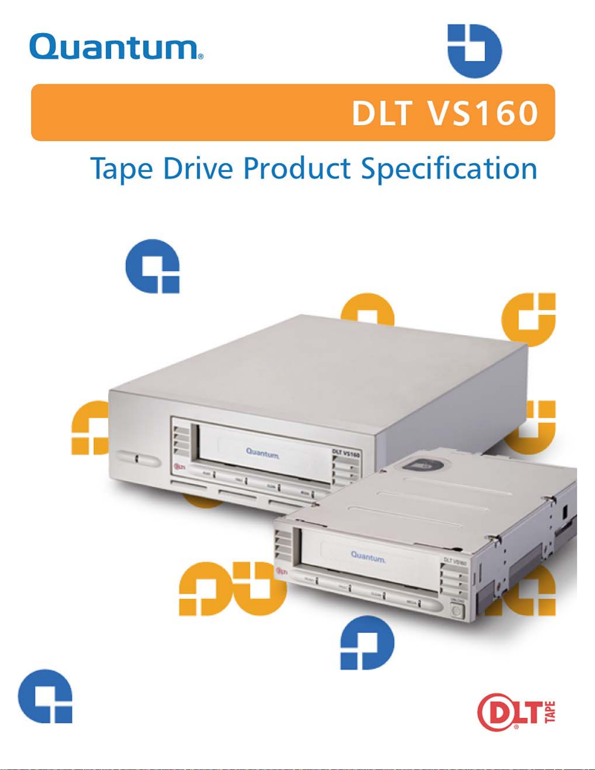
Add cover graphic to the master page in this space. (Ask the Art Director
in Irvine, who works for Elke Hirschmann, to design it for you; it should match
Note: Delete the DLTtape logo and the book title if already included in
the cover artwork.
Page 2

Copyright
Copyright © 2004 by Quantum Corporation. All rights reserved.
Document Origination: Boulder, Colorado, USA.
Trademarks
Quantum, the Quantum logo, and the DLTtape logo are trademarks of Quantum Corporat io n ,
registered in the U.S.A. and other countries. DLT, DLTtape, and DLTSage are trademarks
of Quantum Corporation.
Other company and product names used in this document are trademarks, registered
trademarks, or service marks of their respective owners.
Legal Disclaimers
The information contained in this document is the exclusive property of Quantum Corporation.
Quantum retains its copyright on the information contained herein in all cases and situations of
usage, including derivative works. The possessor agrees to safeguard this information and to
maintain it in confidence and not re-publish it in whole or in part without Quantum’s prior
written consent.
DLT VS160 Product Specification
Quantum reserves the right to make changes and improvements to its products, without
incurring any obligation to incorporate such changes or improvements in units previously sold
or shipped.
It is the responsibility of the user to carefully read and understand the User Manual statements
for Class A Equipment and Class B Equipment that appear on page iii and page iv,
respectively.
Contact Information
You can request Quantum publications from your Quantum Sales Representative or order them
directly from Quantum.
Telephone numbers and street addresses change frequently; for the latest, up-to-date contact
information, visit:
www.quantum.com
Telephone numbers, street addresses, time zones, and other pertinent facts are listed in the
Support section of the web site.
ii September 2004 81-81275-01
Page 3
DLT VS160 Product Specification
Revision History
All revisions made to this document are listed below in chronological order.
Document Release Date Summary of Changes
002287-01 14 December 2002 Initial Release
002287-01 A15 Jan. 22, 2004 Converted to FrameMaker, using Quantum template and St yle
Guide per ECO C008880.
81-81275-01 A01 July 27, 2004 Changed the GB definition from 1,073,741,824 bytes to
1,000,000,000 bytes in the glossary; changed document part
number per ECO C009974.
81-81275-01 A02 Sept. 14, 2004 Minor changes in Chapter 6. Per ECO C011131
User Manual Statements for Class A Equipment
(Internal Tape Drive)
CE Notice (European Union). Marking by the symbol indicates compliance of this tape drive
to the EMC Directive (89/336/EEC), and Low Voltage Directive (73/23/EEC) of the European
Union. Compliance with these directives implies conformity to the following European Norms
(the equivalent international standards and regulations are in parentheses):
• EN 60950/A11: 1997/(IEC 60950/A4: 1996), Safety of Information Technology Equipment including Electrical Business Equipment
• EN 55024: 1998 (IEC 1000-4-2, 1000-4-3, 1000-4-4, 1000-4-5, 1000-4-6, 1000-4-8,
1000-4-11) - “Information technology equipment – Immunity characteristics – Limits and
methods of measurement”
• Part 2 - Electrostatic Discharge (ESD) Requirements
• Part 3 - Radiated Electromagnetic Field Requirements
• Part 4 - Electrical Fast Transient/Burst (EFT) Requirements
• Part 5 - Surge Requirements
• Part 6 - Conducted disturbances, induced by radio-frequency fields Requirements
• Part 8 - Power frequency magnetic field Requirements
• Part 11 – Voltage dips, short interruptions and voltage variations Requirements
• EN 55022:1998/(CISPR 22:1997), Class B, “Limits and Methods of Measurement of
Radio Disturbance Characteristics of Information Technology Equipment.”
The following standards only apply to the tabletop tape drive:
• EN 61000-3-2: 1995, Limits for harmonic current emissions (equipment input) current up
to and including 16 A per phase
• EN 61000-3-3: 1995, Limitation of voltage fluctuations and flicker in low-voltage supply
systems for equipment with rated current up to and including 16A.
FCC Notices (U.S. Only). This device complies with Part 15 of the FCC Rules. Operation is subject
to the following two conditions: (1) this device may not cause harmful interference, and (2)
this device must accept any interference received, including interference that may cause
undesired operation.
81-81275-01 September 2004 iii
Page 4

User Manual Statements for Class B Equipment
(Tabletop Tape Drive)
This equipment has been tested and found to comply with the limits for a Class B digital
device, pursuant to Part 15 of the FCC Rules. These limits are designed to provide reasonable
protection against harmful interference in residential installation. This equipment generates,
uses, and can radiate radio frequency energy and, if not installed and used in accordance with
the instructions, may cause harmful interference to radio communications. However, there is
no guarantee that interference will not occur in a particular installation. If this equipment does
cause harmful interference to radio or television reception, which can be determined by turning
the equipment off and on, the user is encouraged to try to correct the interference by one or
more, of the following measures:
• Reorient or relocate the receiving antenna.
• Increase the separation between the equipment and receiver.
• Connect the equipment into an outlet on a circuit different from that to which the receiver
is connected.
• Consult the dealer or an experienced radio /TV technician for help.
The user may find the following booklet prepared by the Federal Communications
Commission helpful: How to Identify and Resolve Radio-TV Interference Problems. This
booklet is available from the U.S. Government Printing Office, Washington D.C., 20402.
Stock No. 004-00398-5
DLT VS160 Product Specification
All external I/O cables connecting to this unit need to be shielded. See the User Manual or
installation instructions for more options.
Caution Any changes or modifications made to this equipment may void the
user’s authority to operate this equipment.
FCC Label
iv September 2004 81-81275-01
Page 5
DLT VS160 Product Specification
IC Notice (Canada)
This Class [B] digital apparatus complies with Canadian ICES-003.
Cet appareil numérique de la classe [B] est conforme à la norme NMB-003 du Canada.
VCCI Notice (Japan)
Class B ITE Translation:
This is a Class B product based on the standard of the Voluntary Control Council for
Interference from Information Technology Equipment (VCCI). If this product is used near a
radio or television receiver in a domestic environment, it may cause radio interference. Install
and use the equipment according to the instruction manual.
VCCI Class B ITE Regulatory Mark
81-81275-01 September 2004 v
Page 6

DLT VS160 Product Specification
vi September 2004 81-81275-01
Page 7

Ta b l e o f C o n t e n t s
1 Introduction . . . . . . . . . . . . . . . . . . . . . . . . . . . . . . . . . . . . . . . 1-1
Purpose and Scope. . . . . . . . . . . . . . . . . . . . . . . . . . . . . . . . . . . . . . . . . . . . . . . . . . . . . . . . . . . . . . . 1-1
Audience . . . . . . . . . . . . . . . . . . . . . . . . . . . . . . . . . . . . . . . . . . . . . . . . . . . . . . . . . . . . . . . . . . . . . . 1-1
Related Documents . . . . . . . . . . . . . . . . . . . . . . . . . . . . . . . . . . . . . . . . . . . . . . . . . . . . . . . . . . . . . . 1-1
Structure of this Manual . . . . . . . . . . . . . . . . . . . . . . . . . . . . . . . . . . . . . . . . . . . . . . . . . . . . . . . . . . 1-2
Conventions Used in This Manual . . . . . . . . . . . . . . . . . . . . . . . . . . . . . . . . . . . . . . . . . . . . . . . . . . 1-3
Typographical Conventions. . . . . . . . . . . . . . . . . . . . . . . . . . . . . . . . . . . . . . . . . . . . . . . . . . . . . . . . 1-4
Reader Comments . . . . . . . . . . . . . . . . . . . . . . . . . . . . . . . . . . . . . . . . . . . . . . . . . . . . . . . . . . . . . . . 1-4
2 Physical Specifications . . . . . . . . . . . . . . . . . . . . . . . . . . . . . . . 2-1
Physical Description . . . . . . . . . . . . . . . . . . . . . . . . . . . . . . . . . . . . . . . . . . . . . . . . . . . . . . . . . . . . . 2-1
Physical Dimensions and Weights . . . . . . . . . . . . . . . . . . . . . . . . . . . . . . . . . . . . . . . . . . . . . . . 2-1
Environmental Temperature Specifications . . . . . . . . . . . . . . . . . . . . . . . . . . . . . . . . . . . . . . . . 2-3
Environmental Humidity Specifications. . . . . . . . . . . . . . . . . . . . . . . . . . . . . . . . . . . . . . . . . . . 2-3
Internal Tape Drive Mounting Hole Dimensions . . . . . . . . . . . . . . . . . . . . . . . . . . . . . . . . . . . . . . . 2-4
3 Functional Specifications . . . . . . . . . . . . . . . . . . . . . . . . . . . . . 3-1
LED Indicators . . . . . . . . . . . . . . . . . . . . . . . . . . . . . . . . . . . . . . . . . . . . . . . . . . . . . . . . . . . . . . . . . 3-2
Power-On Self-Test (POST) Indicator Activity . . . . . . . . . . . . . . . . . . . . . . . . . . . . . . . . . . . . . 3-2
Normal Operation — Ready LED Indicator Activity. . . . . . . . . . . . . . . . . . . . . . . . . . . . . . . . . 3-2
Normal Operation — Fault / Clean / Media LEDs Indicator Activity . . . . . . . . . . . . . . . . . . . . 3-3
Unload Button Functions. . . . . . . . . . . . . . . . . . . . . . . . . . . . . . . . . . . . . . . . . . . . . . . . . . . . . . . . . . 3-4
Unload Button Actions . . . . . . . . . . . . . . . . . . . . . . . . . . . . . . . . . . . . . . . . . . . . . . . . . . . . . . . . . . . 3-5
Diagnostic Mode Event Codes . . . . . . . . . . . . . . . . . . . . . . . . . . . . . . . . . . . . . . . . . . . . . . . . . . . . . 3-6
81-81275-01 REV A02 September 2004 vii
Page 8

Table of Contents DLT VS160 Product Specification
4 Performance Specifications . . . . . . . . . . . . . . . . . . . . . . . . . . . 4-1
Timing Characteristics. . . . . . . . . . . . . . . . . . . . . . . . . . . . . . . . . . . . . . . . . . . . . . . . . . . . . . . . . . . . 4-1
Data Cartridge and Media Characteristics. . . . . . . . . . . . . . . . . . . . . . . . . . . . . . . . . . . . . . . . . . . . . 4-2
Reliability Factors . . . . . . . . . . . . . . . . . . . . . . . . . . . . . . . . . . . . . . . . . . . . . . . . . . . . . . . . . . . . . . . 4-2
5 Power Specifications. . . . . . . . . . . . . . . . . . . . . . . . . . . . . . . . . 5-1
Current Specifications . . . . . . . . . . . . . . . . . . . . . . . . . . . . . . . . . . . . . . . . . . . . . . . . . . . . . . . . . . . . 5-1
External Power Supply and Chassis Requirements. . . . . . . . . . . . . . . . . . . . . . . . . . . . . . . . . . . . . . 5-2
6 Environmental Specifications . . . . . . . . . . . . . . . . . . . . . . . . . . 6-1
Temperature and Humidity Ranges. . . . . . . . . . . . . . . . . . . . . . . . . . . . . . . . . . . . . . . . . . . . . . . . . . 6-2
Altitude . . . . . . . . . . . . . . . . . . . . . . . . . . . . . . . . . . . . . . . . . . . . . . . . . . . . . . . . . . . . . . . . . . . . . . . 6-2
7 Shock and Vibration Specifications . . . . . . . . . . . . . . . . . . . . . 7-1
Operating Shock and Vibration Specifications . . . . . . . . . . . . . . . . . . . . . . . . . . . . . . . . . . . . . . . . . 7-1
Operating Shock Specifications . . . . . . . . . . . . . . . . . . . . . . . . . . . . . . . . . . . . . . . . . . . . . . . . . 7-1
Operating Vibration Specifications. . . . . . . . . . . . . . . . . . . . . . . . . . . . . . . . . . . . . . . . . . . . . . . 7-2
Non-operating Shock and Vibration Specifications . . . . . . . . . . . . . . . . . . . . . . . . . . . . . . . . . . . . . 7-4
Non-operating Shock Specifications. . . . . . . . . . . . . . . . . . . . . . . . . . . . . . . . . . . . . . . . . . . . . . 7-4
Non-operating Packaged Vibration Specifications. . . . . . . . . . . . . . . . . . . . . . . . . . . . . . . . . . . 7-4
Non-operating Unpackaged Vibration Specifications. . . . . . . . . . . . . . . . . . . . . . . . . . . . . . . . . 7-5
8 Emission and Immunity Specifications. . . . . . . . . . . . . . . . . . . 8-1
Emissions. . . . . . . . . . . . . . . . . . . . . . . . . . . . . . . . . . . . . . . . . . . . . . . . . . . . . . . . . . . . . . . . . . . . . . 8-1
Radiated Emissions. . . . . . . . . . . . . . . . . . . . . . . . . . . . . . . . . . . . . . . . . . . . . . . . . . . . . . . . . . . 8-1
Conducted Emissions . . . . . . . . . . . . . . . . . . . . . . . . . . . . . . . . . . . . . . . . . . . . . . . . . . . . . . . . . 8-2
Harmonic Current Emissions . . . . . . . . . . . . . . . . . . . . . . . . . . . . . . . . . . . . . . . . . . . . . . . . . . . 8-2
Acoustic Noise Emissions. . . . . . . . . . . . . . . . . . . . . . . . . . . . . . . . . . . . . . . . . . . . . . . . . . . . . . 8-3
viii September 2004 81-81275-01 REV A02
Page 9

DLT VS160 Product Specification Table of Contents
Immunities. . . . . . . . . . . . . . . . . . . . . . . . . . . . . . . . . . . . . . . . . . . . . . . . . . . . . . . . . . . . . . . . . . . . . 8-4
Electrostatic Discharge (ESD) Immunity . . . . . . . . . . . . . . . . . . . . . . . . . . . . . . . . . . . . . . . . . . 8-5
Radiated Immunity . . . . . . . . . . . . . . . . . . . . . . . . . . . . . . . . . . . . . . . . . . . . . . . . . . . . . . . . . . . 8-5
Fast Transient Immunity. . . . . . . . . . . . . . . . . . . . . . . . . . . . . . . . . . . . . . . . . . . . . . . . . . . . . . . 8-5
Surge Immunity. . . . . . . . . . . . . . . . . . . . . . . . . . . . . . . . . . . . . . . . . . . . . . . . . . . . . . . . . . . . . . 8-6
Conducted Immunity. . . . . . . . . . . . . . . . . . . . . . . . . . . . . . . . . . . . . . . . . . . . . . . . . . . . . . . . . . 8-6
Power Frequency Magnetic Field Immunity . . . . . . . . . . . . . . . . . . . . . . . . . . . . . . . . . . . . . . . 8-6
Voltage Dips, Short Interruptions, and Variations Immunity . . . . . . . . . . . . . . . . . . . . . . . . . . . 8-7
Voltage Fluctuations and Flicker Limits . . . . . . . . . . . . . . . . . . . . . . . . . . . . . . . . . . . . . . . . . . . . . . 8-7
Direct Current (DC) Magnetic Field Interference. . . . . . . . . . . . . . . . . . . . . . . . . . . . . . . . . . . . . . . 8-7
9 Safety Specifications. . . . . . . . . . . . . . . . . . . . . . . . . . . . . . . . . 9-1
Safety Requirement . . . . . . . . . . . . . . . . . . . . . . . . . . . . . . . . . . . . . . . . . . . . . . . . . . . . . . . . . . . . . . 9-1
Consumer Bulletin Scheme. . . . . . . . . . . . . . . . . . . . . . . . . . . . . . . . . . . . . . . . . . . . . . . . . . . . . . . . 9-1
G Glossary . . . . . . . . . . . . . . . . . . . . . . . . . . . . . . . . . . . . . . . . . .G-1
81-81275-01 REV A02 September 2004 ix
Page 10

Table of Contents DLT VS160 Product Specification
Notes
x September 2004 81-81275-01 REV A02
Page 11

List of Tables
1 Introduction . . . . . . . . . . . . . . . . . . . . . . . . . . . . . . . . . . . . . . . 1-1
Table 1-1. Chapters in this Manual . . . . . . . . . . . . . . . . . . . . . . . . . . . . . . . . . . . . . . . . . . . . . . . . . . 1-2
Table 1-2. Typographical Conventions . . . . . . . . . . . . . . . . . . . . . . . . . . . . . . . . . . . . . . . . . . . . . . . 1-4
2 Physical Specifications . . . . . . . . . . . . . . . . . . . . . . . . . . . . . . . 2-1
Table 2-1. Physical Dimensions . . . . . . . . . . . . . . . . . . . . . . . . . . . . . . . . . . . . . . . . . . . . . . . . . . . . 2-1
Table 2-2. Weight Specifications. . . . . . . . . . . . . . . . . . . . . . . . . . . . . . . . . . . . . . . . . . . . . . . . . . . . 2-1
Table 2-3. Proper and Acceptable DLT VS160 Tape Drive Orientation. . . . . . . . . . . . . . . . . . . . . . 2-2
Table 2-4. Environmental Temperature Specifications . . . . . . . . . . . . . . . . . . . . . . . . . . . . . . . . . . . 2-3
Table 2-5. Environmental Humidity Specifications . . . . . . . . . . . . . . . . . . . . . . . . . . . . . . . . . . . . . 2-3
3 Functional Specifications . . . . . . . . . . . . . . . . . . . . . . . . . . . . . 3-1
Table 3-1. Functional Specifications. . . . . . . . . . . . . . . . . . . . . . . . . . . . . . . . . . . . . . . . . . . . . . . . . 3-1
Table 3-2. Normal Operation — Ready LED Indicator Activity . . . . . . . . . . . . . . . . . . . . . . . . . . . 3-2
Table 3-3. Normal Operation — Fault / Clean / Media LEDs Indicator Activity. . . . . . . . . . . . . . . 3-3
Table 3-4. Unload Button Functions . . . . . . . . . . . . . . . . . . . . . . . . . . . . . . . . . . . . . . . . . . . . . . . . . 3-4
Table 3-5. Unload Button Actions. . . . . . . . . . . . . . . . . . . . . . . . . . . . . . . . . . . . . . . . . . . . . . . . . . . 3-5
Table 3-6. Diagnostic Mode Event Codes. . . . . . . . . . . . . . . . . . . . . . . . . . . . . . . . . . . . . . . . . . . . . 3-6
4 Performance Specifications . . . . . . . . . . . . . . . . . . . . . . . . . . . 4-1
Table 4-1. Timing Characteristics of the Tape Drive. . . . . . . . . . . . . . . . . . . . . . . . . . . . . . . . . . . . . 4-1
Table 4-2. Data Cartridge and Media Characteristics . . . . . . . . . . . . . . . . . . . . . . . . . . . . . . . . . . . . 4-2
Table 4-3. Reliability Factors for the Tape Drive . . . . . . . . . . . . . . . . . . . . . . . . . . . . . . . . . . . . . . . 4-2
81-81275-01 REV A02 September 2004 xi
Page 12

List of Tables DLT VS160 Product Specification
5 Power Specifications. . . . . . . . . . . . . . . . . . . . . . . . . . . . . . . . . 5-1
Table 5-1. Current Specifications of the Tape Drive. . . . . . . . . . . . . . . . . . . . . . . . . . . . . . . . . . . . . 5-1
Table 5-2. Common Mode Noise Limitations. . . . . . . . . . . . . . . . . . . . . . . . . . . . . . . . . . . . . . . . . . 5-2
6 Environmental Specifications . . . . . . . . . . . . . . . . . . . . . . . . . . 6-1
Table 6-1. Operating — Temperature and Humidity Ranges . . . . . . . . . . . . . . . . . . . . . . . . . . . . . . 6-2
Table 6-2. Storage and Shipment — Temperature and Humidity Ranges (Packed or Unpacked) . . 6-2
7 Shock and Vibration Specifications . . . . . . . . . . . . . . . . . . . . . 7-1
Table 7-1. Operating — Half Sine Wave Pulse Shock Specifications . . . . . . . . . . . . . . . . . . . . . . . 7-1
Table 7-2. Random — Operating Vibration Specifications. . . . . . . . . . . . . . . . . . . . . . . . . . . . . . . . 7-2
Table 7-3. Random — Operating Vibration Specifications (PSD Spectrum). . . . . . . . . . . . . . . . . . 7-2
Table 7-4. Random Overstress — Operating Vibration Specifications. . . . . . . . . . . . . . . . . . . . . . . 7-2
Table 7-5. Random Overstress — Operating Vibration Specifications (PSD Spectrum) . . . . . . . . . 7-3
Table 7-6. Sweep / Dwell — Operating Vibration Specifications. . . . . . . . . . . . . . . . . . . . . . . . . . . 7-3
Table 7-7. Non-operating (Unpackaged) — Shock Specifications. . . . . . . . . . . . . . . . . . . . . . . . . . 7-4
Table 7-8. Random Survival — Non-operating (Packaged) Vibration Specifications . . . . . . . . . . . 7-4
Table 7-9. Sweep/Dwell — Non-operating (Packaged) Vibration Specifications . . . . . . . . . . . . . . 7-5
Table 7-10. Impact Drop — Non-operating (Packaged) Shock (Drop) Specifications. . . . . . . . . . . 7-5
Table 7-11. Random — Non-operating (Unpackaged) Vibration Specifications . . . . . . . . . . . . . . . 7-5
Table 7-12. Standalone — Random Non-operating (Unpackaged) Vibration Specifications (PSD
Spectrum). . . . . . . . . . . . . . . . . . . . . . . . . . . . . . . . . . . . . . . . . . . . . . . . . . . . . . . . . . . . . . . . . . . . . . 7-6
Table 7-13. Sweep/Dwell — Non-operating (Unpackaged) Vibration Specifications . . . . . . . . . . . 7-6
xii September 2004 81-81275-01 REV A02
Page 13

DLT VS160 Product Specification List of Tables
8 Emission and Immunity Specifications. . . . . . . . . . . . . . . . . . . 8-1
Table 8-1. Radiated Emissions Limits. . . . . . . . . . . . . . . . . . . . . . . . . . . . . . . . . . . . . . . . . . . . . . . . 8-1
Table 8-2. Conducted Emissions Limits . . . . . . . . . . . . . . . . . . . . . . . . . . . . . . . . . . . . . . . . . . . . . . 8-2
Table 8-3. Odd Harmonic Limits for Class A Equipment Limits . . . . . . . . . . . . . . . . . . . . . . . . . . . 8-2
Table 8-4. Even Harmonic Limits for Class A Equipment . . . . . . . . . . . . . . . . . . . . . . . . . . . . . . . . 8-3
Table 8-5. Acoustic Noise Emissions, Nominal . . . . . . . . . . . . . . . . . . . . . . . . . . . . . . . . . . . . . . . . 8-3
Table 8-6. Acoustic Noise Declaration for German Noise Declaration Law . . . . . . . . . . . . . . . . . . 8-4
Table 8-7. Electrostatic Discharge (ESD) Immunity Limits . . . . . . . . . . . . . . . . . . . . . . . . . . . . . . . 8-5
Table 8-8. Radiated Immunity Limits . . . . . . . . . . . . . . . . . . . . . . . . . . . . . . . . . . . . . . . . . . . . . . . . 8-5
Table 8-9. Fast Transient Immunity Limits. . . . . . . . . . . . . . . . . . . . . . . . . . . . . . . . . . . . . . . . . . . . 8-5
Table 8-10. Surge Immunity Limits. . . . . . . . . . . . . . . . . . . . . . . . . . . . . . . . . . . . . . . . . . . . . . . . . . 8-6
Table 8-11. Conducted Immunity Limits. . . . . . . . . . . . . . . . . . . . . . . . . . . . . . . . . . . . . . . . . . . . . . 8-6
Table 8-12. Magnetic Field Immunity Limits . . . . . . . . . . . . . . . . . . . . . . . . . . . . . . . . . . . . . . . . . . 8-6
Table 8-13. Voltage Dips, Short Interruptions, and Variations Immunity Limits . . . . . . . . . . . . . . . 8-7
Table 8-14. Voltage Fluctuations and Flicker Limits. . . . . . . . . . . . . . . . . . . . . . . . . . . . . . . . . . . . . 8-7
9 Safety Specifications. . . . . . . . . . . . . . . . . . . . . . . . . . . . . . . . . 9-1
81-81275-01 REV A02 September 2004 xiii
Page 14

List of Tables DLT VS160 Product Specification
Notes
xiv September 2004 81-81275-01 REV A02
Page 15

List of Figures
2 Physical Specifications . . . . . . . . . . . . . . . . . . . . . . . . . . . . . . . 2-1
Figure 2-1. Internal Tape Drive Mounting Hole Dimensions (Bottom View) . . . . . . . . . . . . . . . . . 2-4
Figure 2-2. Mounting Hole Dimensions (Side View) . . . . . . . . . . . . . . . . . . . . . . . . . . . . . . . . . . . . 2-5
81-81275-01 REV A02 September 2004 xv
Page 16

List of Figures DLT VS160 Product Specification
Notes
xvi September 2004 81-81275-01 REV A02
Page 17

This chapter describes the purpose, scope, and audience of this manual. It also lists related
documentation and the conventions used in this manual.
1.1 Purpose and Scope
This manual describes the DLT VS160 tape drive, listing its physical, functional, and performance
specifications, and describing the standards that the tape drive meets.
CHAPTER 1
Chapter 1Introduction
1.2 Audience
The primary audience for this manual consists of engineers and technicians interested in integrating
the DLT VS160 tape drive into tape libraries and other equipment.
1.3 Related Documents
• DLT VS160 Tape Drive Installation and Operations Guide (81-81191-01)
• DLT VS160 SCSI Interface Guide (81-81268-01)
81-81275-01 REV A02 September 2004 1-1
Page 18

Structure of this Manual DLT VS160 Product Specification
1.4 Structure of this Manual
The manual contains the chapters listed in Table 1-1.
Table 1- 1. Chapters in this Manual
Chapter Description
Chapter 1, “Introduction” This is the chapter you are reading now.
Chapter 2, “Physical
Specifications”
Chapter 3, “Functional
Specifications”
Chapter 4, “Performance
Specifications”
Chapter 5, “Power Specifications” Describes the power specifications of the tape drive.
Chapter 6, “Environmental
Specifications”
Chapter 7, “Shock and Vibration
Specifications”
Chapter 8, “Emission and
Immunity Specifications”
Chapter 9, “Safety Specifications” Describes the safety specifications to which the tape drive complies.
“Glossary” Provides a list of technical terms commonly used in the computer
Contains the physical description of the tape drive, including the
environmental temperature and humidity specifications. This chapter
also shows the tape drive’s mounting hole dimensions.
Contains the functional specifications of the tape drive, including the
LED functions.
Describes the performance specifications of the tape drive, including
timing, media, and the reliability of the tape drive.
This chapter describes the tape drive’s environmental specifications.
Describes the shock and vibration specifications of the tape drive.
Describes the emission and immunity specifications of the tape drive.
industry and abbreviations specifically used in this manual.
1-2 September 2004 81-81275-01 REV A02
Page 19

DLT VS160 Product Specification Chapter 1: Introduction
1.5 Conventions Used in This Manual
This manual uses the following conventions:
NOTE: Notes provide supplemental information.
T
ECH TIP: Tech Tips provide information that helps you complete a procedure or
avoid additional steps.
AUTION Cautions provide information you must know to avoid
C
damaging the tape drive or losing data.
ARNING! Warnings provide information you must know to avoid
W
personal injury.
81-81275-01 REV A02 September 2004 1-3
Page 20

Typographical Conventions DLT VS160 Product Specification
1.6 Typographical Conventions
This manual uses the following conventions to designate specific elements.
Table 1-2. Typographical Conventions
Element Convention Example
Commands Uppercase (unless case-sensitive) FORMAT UNIT
Messages Uppercase INVALID PRODUCT
NUMBER
Hexadecimal Notation Number followed by lowercase h 25h
Binary Notation Number followed by lowercase b 101b
Decimal Notation Number without suffix 512
Acronyms Uppercase POST
Abbreviations Lowercase, except where standard
usage requires uppercase
Dimensions in Figures No units specified (Inches understood
unless otherwise specified)
1.7 Reader Comments
Quantum is committed to providing the best products and service. We encourage your comments,
suggestions, and corrections for this manual. Please send all comments to this address:
Quantum Technical Publications
4001 Discovery Dr.
Suite 1100
Boulder, Colorado USA 80 303
Mb (megabits)
MB (megabytes)
0.57 EJECT DISTANCE
1-4 September 2004 81-81275-01 REV A02
Page 21

Chapter 2Physical Specifications
This chapter contains the physical description of the DLT VS160 tape drive, including the internal and
tabletop tape drives, and the environmental temperature and humidity specifications.
2.1 Physical Description
2.1.1 Physical Dimensions and Weights
CHAPTER 2
Table 2-1. Physical Dimensions
Specification Internal Tape Drive Tabletop Tape Drive
Height 1.656 in. (42.05 mm) with bezel
1.618 in. (41.10 mm) without bezel
Width 5.748 in. (146.00 mm) behind bezel
5.807 in. (147.50 mm) with bezel
Length 8.571 in. (217.70 mm) measured from back
of front bezel
8.770 in. (222.75 mm) including the bezel
Table 2-2. Weight Specifications
Specification Internal Tape Drive Tabletop Tape Drive
Unit Weight 3.00 lb (1.36 kg) 8.00 lb (3.63 kg)
Shipping
Weight
4.39 lb (1.99 kg) depending on
configuration
2.608 in. (66.24 mm)
8.352 in. (212.13 mm)
10.728 in. (272.49 mm)
11.81 lb (5.36 kg) depending on the
configuration
81-81275-01 REV A02 September 2004 2-1
Page 22

Physical Description DLT VS160 Product Specification
Table 2-3 shows the acceptable operating orientation for the DLT VS160 tape drive.
Table 2-3. Proper and Acceptable DLT VS160 Tape Drive Orientation
Orientation Internal Tape Drive
(looks like this)
Top Side Up
(typical)
Left Side Down
Tabletop Tape Drive
(looks like this)
Right Side
Down
2-2 September 2004 81-81275-01 REV A02
Page 23

DLT VS160 Product Specification Chapter 2: Physical Specifications
2.1.2 Environmental Temperature Specifications
Table 2-4. Environmental Temperature Specifications
Specification Value
Operating
Non-operating
Airflow
50 ºF to 104 °F (10 ºC to 40 °C)
-40 ºF to 150.8 °F (-40 ºC to 66 °C)
3.0 Cubic Feet per Minute (CFM) minimum
2.1.3 Environmental Humidity Specifications
Table 2-5. Environmental Humidity Specifications
Specification Value
Operating
Non-operating
20% to 80% non-condensing
10% to 95%
81-81275-01 REV A02 September 2004 2-3
Page 24

Internal Tape Drive Mounting Hole Dimensions DLT VS160 Product Specification
139.7 ± 0.381
[5.500 ± .015]
79.38 ± 0.25
[ 3.125 ± .010 ]
48.52± 0.254
[ 1.910 ± .010 ]
124.84
[ 4.92 ]
105.41
[ 4.15 ]
127.99
[ 5.04 ]
22.58 ± 0.55
[ .889 ± .021 ]
19.43 ± 0.7
[ .765 ± .027 ]
1
2
3
2.2 Internal Tape Drive Mounting Hole Dimensions
Figure 2-1 shows the mounting holes and dimensions in a bottom view for the internal tape drive.
Data cartridge
Figure 2-1. Internal Tape Drive Mounting Hole Dimensions (Bottom View)
N
OTES:1The dimension referenced in boxed note 1 [1] is from the front of the base plate.
2 The dimension referenced in boxed note 2 [2] is from the right-side tape drive mounting plane to the
interior guiding surface of the media opening.
3 The dimension referenced in boxed note 3 [3] is from the bottom tape drive mounting hole to the
interior guiding surface of the media opening.
4 The tape drive width and length are standard 5¼-inch form factor measurements.
5 Dimensions are identical on left side and right sides.
6 Dimensions are in millimeters. The dimensions in brackets [x.x] are in inches.
2-4 September 2004 81-81275-01 REV A02
Page 25

DLT VS160 Product Specification Chapter 2: Physical Specifications
Figure 2-2 shows the mounting holes and dimensions in a side view for the internal tape drive.
±
52.37 .381
±
[ 2.062 .015 ]
Data
cartridge
5
+1
-3
+1
-3
+1
-3
+1
-3
±
13 .381
±
+.039
[.610 ]
-.118
+.039
[.807 ]
-.118
+.039
[1.003 ]
-.118
+.039
[1.161 ]
15.5
20.5
25.5
Standard Distance
29.5
[ .512 .015 ]
-.118
4
41.5 MAX
[ 1.633 ] MAX
±
21.79 .254
±
[ .858 .010 ]
10 .254
[ .394 .010 ]
±
±
12X M3, Max Screw
Insertion 10 MM
±
219.6 .254
±
[ 8.65 .011 ]
79.38 .254
[ 3.125 .010 ]
1
±
±
Figure 2-2. Mounting Hole Dimensions (Side View)
OTES:1The dimension referenced in boxed note 1 [1] is from the front of the base plate.
N
2 The dimension referenced in boxed note 4 [4] is from the bottom tape drive mounting plane to the
interior guiding surface of the media opening.
3 Boxed note 5 [5] states that the data cartridge is shown in the ejected position.
4 The tape drive width and length are standard 5¼-inch form factor measurements.
5 Dimensions are identical on left side and right sides.
6 Dimensions are in millimeters. The dimensions in brackets [x.x] are in inches.
81-81275-01 REV A02 September 2004 2-5
Page 26

Internal Tape Drive Mounting Hole Dimensions DLT VS160 Product Specification
Notes
2-6 September 2004 81-81275-01 REV A02
Page 27

CHAPTER 3
Chapter 3Functional Specifications
This chapter contains the functional specifications of the DLT VS160 tape drive, including the LED
functions.
This table lists the key functional specifications of the DLT VS160 tape drive.
Table 3-1. Functional Specifications
Specification Value
Formatted Capacity, Native Mode 80 gigabytes (GB)
Formatted Capacity, Compressed Mode
a
160 GB
Interface Wide Ultra SCSI 2, Low-Voltage Differential (LVD)
Tape Drive Type DLT Derivative, streaming, 80 / 160 GB; 16-bit LVD
Recording Type Partial Response Maximum Likelihood (PRML)
Read Compatibility
b
DLT VS160, DLT VS80 / DLT1
Write Compatibility DLT VS160
Form Factor
¼-in. Half-height
5
Transfer Rate, Native Mode 8.0 megabyte (MB) per second
Transfer Rate, Compressed Mode
a
Up to 16.0 MB / sec
Transfer Rate, Burst 160 MB / sec
Error Rate (Unrecoverable)
a. Compressed values use a nominal 2:1 compression ratio. Actual compression ratios achieved depend on the redundancy of
data files being recorded.
b. Performance may vary when the tape drive reads data previously written to the DLT VS80 and DLT1 formatted data
cartridges. Performance depends on the quality of the data cartridge you are reading, not the DLT VS160 tape drive.
1 in 10
17
bits (non-media error, clean tape drive)
81-81275-01 REV A02 September 2004 3-1
Page 28

LED Indicators DLT VS160 Product Specification
3.1 LED Indicators
The tape drive has four light emitting diodes (LEDs). This section describes the functions of the LEDs.
NOTE: The front panel controls and indicators are in the same locations on both
the internal and tabletop tape drives. The tabletop tape drive has a Power
LED.
3.1.1 Power-On Self-Test (POST) Indicator Activity
Each time you apply power to the tape drive, or reset the tape drive, it performs a power-on self-test
(POST). During POST, the LEDs illuminate one at a time, from left to right. First, the Ready LED
(Green) comes on, followed by the Fault LED (Orange) approximately one second later, then the
Clean LED (Orange) approximately one second later, then four seconds later the Media LED
(Orange) illuminates. Each LED signifies a different portion of the power-on process. All LEDs turn
off momentarily. If no data cartridge is loaded in the tape drive, the Ready LED then illuminates
steadily and POST is complete. This process takes approximately eight seconds. If a data cartridge is
in the tape drive during POST, the Ready LED flashes until the tape drive executes a mid-tape load,
which can take several minutes. As POST completes, the tape drive makes a faint buzzing noise for
several seconds. The noise associated with this activity is normal for this technology and does not
indicate a problem with the tape drive.
3.1.2 Normal Operation — Ready LED Indicator Activity
During normal operation, the Ready LED displays one of the three following states. The Ready LED
acts independently of the other LEDs.
Table 3-2. Normal Operation — Ready LED Indicator Activity
State Description
Off Indicates that there is no power to the tape drive.
On Indicates that power is on, no data cartridge is loaded, or a loaded data cartridge is
idle with no tape motion.
Blinking A data cartridge is in the process of loading, or there is tape motion on a loaded data
cartridge. Tape motion includes reading, writing, locating, rewinding, calibrating,
and so on.
3-2 September 2004 81-81275-01 REV A02
Page 29

DLT VS160 Product Specification Chapter 3: Functional Specifications
3.1.3 Normal Operation — Fault / Clean / Media LEDs
Indicator Activity
The Fault, Clean, and Media LEDs work together to display the status of the tape drive.
Table 3-3. Normal Operation — Fault / Clean / Media LEDs Indicator Activity
Fault Clean Media Description
– Unsupported format, unsupported data cartridge type, or
damaged data cartridge
A DLT1 (DLT VS 80) formatted DLTtape™ IV data
cartridge is loaded.
– Calibration error or permanent write/read error
Cleaning required—250 tape motion hours exceeded since
last cleaning
– Cleaning in process
Key
–Off
User invoked write/read diagnostic failed
Servo or mechanical error
– – Internal firmware error
On
Blinking–slow (approximately once per second)
Blinking–medium (approximately twice per second)
Blinking–fast (approximately three times per second)
Indicates that the status of this LED does not depend on the specific tape drive condition. This
means that certain tape drive conditions may result in a combination of two or more of the
LED states in the chart.
For example, if you need to clean the tape drive while a DLT1 tape is loaded, both the Clean
LED and Media LED are on steadily. If an internal write/read diagnostic fails due to a
permanent write error, both the Fault LED and Clean LED blink slowly.
81-81275-01 REV A02 September 2004 3-3
Page 30

Unload Button Functions DLT VS160 Product Specification
3.2 Unload Button Functions
You can use the unload button to unload and eject data cartridges, and for the additional features
shown in the following table. Press and hold the eject button for the time specified in the following
table to activate one of these features. Release the button when the LEDs display the desired sequence.
C
AUTION The two features noted in the following table will over-write
any data on the data cartridge. Do not use these features if the
data cartridge in the tape drive contains critical data.
Table 3-4. Unload Button Functions
Description
Normal unload function 0 to 6
Reserved –––6 to 9
Enter code load tape mode – – 9 to 12
Reserved – 12 to 15
Reserved 15 to 18
Revert back to normal mode – – – 18 to 21
Read/write diagnostic start.
CAUTION: This featur e overwrites any
data currently on the data cartridge.
Reserved.
CAUTION: This featur e overwrites any
data currently on the data cartridge.
Emergency Reset 27 to 30
Ready
(green)
Fault
(orange or
clear)
Clean
(orange or
clear)
– – 21 to 24
Media
(orange or
clear)
– 24 to 27
Hold Time
(seconds)
Revert back to normal mode ––––30+
Key
– Off
Blinking
3-4 September 2004 81-81275-01 REV A02
On (orange or green)
Unchanged from previous condition
Page 31

DLT VS160 Product Specification Chapter 3: Functional Specifications
3.3 Unload Button Actions
This section describes what happens when you release the unload button (as indicated in the previous
section).
Table 3-5. Unload Button Actions
Function/Mode Action
Normal unload function Release the unload button to unload the data cartridge.
Enter code load tape mode Release the unload button to accept a data cartridge that contains the
firmware image (code load). The LEDs then indicate code load mode.
Insert the data cartridge to begin the code update. The tape drive returns to
normal operation if you do not load a data cartridge within 15 seconds.
Read/write diagnostic start CAUTION: This feature overwrites any data currently on the data
cartridge. Before performing this action, confirm that the data cartridge in
the tape drive does not contain critical data.
Release the unload button to start an internal read/write diagnostic. You
must load a data cartridge to run the diagnostic. The tape drive writes and
reads 400 MB of data, then unloads the data cartridge. This process takes
approximately two minutes. The tape drive returns to normal operation if it
detects no errors. The appropriate LEDs illuminate if an error occurs.
Emergency reset Release the unload button to force an internal reset. The tape drive
initializes as if you turned power off and then on (POST).
Revert back to normal mode Release the unload button to return the tape drive to normal operation.
81-81275-01 REV A02 September 2004 3-5
Page 32

Diagnostic Mode Event Codes DLT VS160 Product Specification
3.4 Diagnostic Mode Event Codes
Press, hold, and release the unload button after six to nine seconds to start the diagnostic mode. This
displays the most recent event code. The unload button then becomes a scroll button for additional
event codes. Press and release the unload button for the next most recent event code. You can display
up to five total events using this method. Refer to Table 3-6 for details about the meaning of the
various patterns.
After you display the final available event code, the next button press causes all LEDs to flash
indicating that the next eight hex characters displayed are the detailed error code of the most recent
event. The first character is either a hex E (error) or a B (bug check). You can look up the remaining
seven characters in the error/bug check definition tables. When you display the last (eighth) detailed
error code digit, the next button press returns the tape drive to normal operation. All indications are a
four bit hex value.
During any time in this procedure, the tape drive returns to normal operation if you perform no scroll
action within 15 seconds.
Table 3-6. Diagnostic Mode Event Codes
LED Fault Code Failure
0001 SCSI Event
0010 General Error
0011 Software Bug Check
0100 Permanent Write Error
0101 Permanent Read Error
0110 Servo Fault
0111 Code Update was Completed
1000 Illegal Format
1001 Invalid Cartridge
1010 Calibration Failure
1011 Cleaning was Completed
1100 Directory Read or Write Failed
1101 Diagnostic Failed
1110 POST Failure
1111 Reserved
3-6 September 2004 81-81275-01 REV A02
Page 33

Chapter 4Performance Specifications
This chapter describes the performance specifications of the DLT VS160 tape drive, including timing
characteristics, data cartridge and media characteristics, and the reliability factors of the tape drive.
4.1 Timing Characteristics
Table 4-1 lists the timing characteristics of the DLT VS160.
Table 4-1. Timing Characteristics of the Tape Drive
CHAPTER 4
Specification Value
Read/Write Tape Speed 122 inches per second
Rewind Tape Speed 160 inches per second
Linear Search Tape Speed 122 inches per second
Average Rewind Time 68 seconds
Maximum Rewind Time 135 sec
Average Access Time (BOT) 90 sec
Maximum Access Time (from BOT) 180 sec
Load to BOT — previously recorded tape 120 sec
Unload from BOT 25 sec
81-81275-01 REV A02 September 2004 4-1
Page 34

Data Cartridge and Media Characteristics DLT VS160 Product Specification
4.2 Data Cartridge and Media Characteristics
Table 4-2 lists the data cartridge and media characteristics.
Table 4-2. Data Cartridge and Media Char acteristics
Characteristic Specification
Media Width 0.5 in.
Media Length 1,847 ft
Media Type Metal Particle
Data Cartridge Dimensions 4.1 in. x 4.1 in. x 1.0 in.
Shelf Life 30 years minimum @ 20 ºC and 40% relative
humidity (non-condensing)
Usage 1,000,000 passes (typical office/computer
environment)
4.3 Reliability Factors
Table 4-3 lists the reliability factors for the DLT VS160 tape drive.
Table 4-3. Reliability Factors for the Tape Drive
Factor Hours / Cycles Comments
Head Life 30,000 tape motion hours Continuous operation.
MTBF 250,000 hours Quantum Corporation does not warrant that
Load/Unload 50,000 cycles This excludes media errors.
predicted MTBF is representative of any
particular unit installed for customer use.
Actual figures vary from unit to unit.
MTBF is measured at 100% duty cycle,
excluding head life.
4-2 September 2004 81-81275-01 REV A02
Page 35

Chapter 5Power Specifications
This chapter describes the power specifications of the DLT VS160 tape drive.
5.1 Current Specifications
CHAPTER 5
NOTE: The +5 Volt bus is 5%; the +12 Volt bus is 10%.
±±
Table 5-1. Current Specifications of the Tape Drive
Mode 5V
Power Up 2.1 1.0 0.9 0.3 8.4 9 18
Load Tape 1.6 1.1 2.7 0.7 13.2 16 24
Unload Tape 1.6 1.0 2.6 0.8 14.1 16 24
Write Tape 1.8 1.6 1.3 0.5 14.6 20 21
Read Tape 1.7 1.4 1.3 0.5 13.3 19 21
Rewind 1.0 0.9 1.4 0.6 11.6 17 19
Idle (tape) 1.0 1.0 0.3 0.2 6.7 13 14
Idle (no tape) 1.0 1.0 0.1 0.1 5.6 11 12
DC
Apk
5V
DC
Arms
12V
Apk
DC
12V
Arms
DC
DC Pwr
W (typ)
AC Pwr
W (typ)
AC Pwr
W (max)
81-81275-01 REV A02 September 2004 5-1
Page 36

External Power Supply and Chassis Requirements DLT VS160 Product Specification
5.2 External Power Supply and Chassis Requirements
This section lists the common mode noise limitations between enclosures. The noise level can not
exceed the values listed in the following table. You must take all measurements with an active or
differential probe to reduce oscilloscope ground loops.
Table 5-2. Common Mode Noise Limitations
First Enclosure Second Enclosure Common Mode Noise Limit
Millivolt (mV)
Enclosure Chassis
(Host Server, Workstati on, or
DLT VS160 Tabletop Enclosure)
Enclosure Chassis
(Host Server, Workstati on, or
DLT VS160 Tabletop Enclosure)
DLT VS160 Tape Drive Chassis <1 mV
Peak to Peak
Power Supply Enclosure Ground <300 mV
Peak to Peak
5-2 September 2004 81-81275-01 REV A02
Page 37

CHAPTER 6
Chapter 6Environmental Specifications
This chapter describes the environmental specifications of the DLT VS160 tape drive.
The tape drive operates in environments that include general offices and workspaces that consist of:
• Conditioned and marginally-conditioned areas with central or remote air-conditioning
• Complete temperature and humidity controls
• Moderate control tolerances
• Systems capable of maintaining consistent comfort levels.
The tape drive does not conform to environments that consist of:
• Marginal heating or cooling apparatus
• No humidity conditioning
• Uncontrolled tolerances
• Systems inadequate to maintain constant comfort levels.
For long-term trouble-free operation, we strongly recommend that you operate and store your
DLT VS160 tape drive in a clean, smoke-free environment.
The following tables provide the operating, non-operating, storage, and shipping environmental
specifications for the DLT VS160 tape drive systems (both the internal and the tabletop
configurations).
81-81275-01 REV A02 September 2004 6-1
Page 38

Temperature and Humidity Ranges DLT VS160 Product Specification
6.1 Temperature and Humidity Ranges
Table 6-1 lists the operating temperature and humidity ranges of the tape drive.
Table 6-1. Operating — Temperature and Humidity Ranges
Specification Value
Temperature Range 10 ºC to 40 ºC (50 ºF to 104 ºF)
Airflow 3.0 CFM (min.)
Wet Bulb Temperature 25 ºC (77 ºF)
Temperature Gradient 11 ºC (19.8 ºF) per hour (across range)
Temperature Shock 10 ºC (18 ºF) over two minutes
Relative Humidity 20% to 80% non-condensing
Humidity Gradient 10% per hour
Table 6-2 lists the storage and shipment temperature and humidity ranges of the tape drive.
Table 6-2. Storage and Shipme nt — Temperature and Humidity Ranges (Packed or Unpacked)
Specification Value
Dry Bulb Temperature
Wet Bulb Temperature 46 ºC (114.8 ºF)
Temperature Gradient 20 ºC (36 ºF) per hour with 5º margin (across the range)
Temperature Shock 15 ºC (27 ºF) with 5º margin (over two minutes)
Relative Humidity 10% to 95% non-condensing
Humidity Gradient 10% per hour
6.2 Altitude
The tape drive operates normally in pressures from -500 feet to 30,000 feet.
-40 ºC to 66 ºC (-40 ºF to 150.8 ºF)
6-2 September 2004 81-81275-01 REV A02
Page 39

CHAPTER 7
Chapter 7Shock and Vibration
Specifications
This chapter describes the shock and vibration specifications of the DLT VS160 tape drive. All testing
was done on both the internal and tabletop tape drives.
7.1 Operating Shock and Vibration Specifications
7.1.1 Operating Shock Specifications
Table 7-1 lists the shock specifications for the tape drive while it is operating.
Table 7-1. Operating — Half Sine Wave Pulse Shock Specifications
Specification 5 G Shock 8 G Shock 62 G Shock
Pulse Shape ½ Sine Pulse ½ Sine Pulse ½ Sine Pulse
Peak Acceleration 5 G 8 G 62 G
Duration 11 millisecond (ms) 10 ms 2 ms
Application X, Y, and Z axis, 10 pulses
per axis ( ), 60 total, 1
pulse every 6 seconds
±±±
X, Y, and Z axis, 1 pulse
per axis ( ), 6 total
X, Y, and Z axis, 1 pulse
per axis ( ), 6 total
81-81275-01 REV A02 September 2004 7-1
Page 40

Operating Shock and Vibration Specifications DLT VS160 Product Specification
7.1.2 Operating Vibration Specifications
Table 7-2, Table 7-3, Table 7-4, Table 7-5, and Table 7-6 list the vibration specifications for the tape
drive while it is operating.
Table 7-2. Random — Operating Vibration Specifications
Factor Criteria Comments
Frequency Range 5 to 50 Hertz (Hz)
Acceleration Level 0.25 G
Application X, Y, and Z axis Top to bottom, 10 minutes per axis
rms
(min.)
Table 7-3. Random — Operating Vibration Specifications (PSD Spectrum)
Power Spectral Density (PSD) Spectrum
(G
PSD
2
/Hz)
Frequency
(Hz)
5 0.00005
20 0.00017
200 0.00017
500 0.000065
Table 7-4. Random Overstress — Operating Vibration Specifications
Factor Criteria Comments
Frequency Range 10 to 500 Hz
Acceleration Level 0.5 G
Application X, Y, and Z axis Top to bottom, 10 minutes per axis
7-2 September 2004 81-81275-01 REV A02
rms
(min.)
Page 41

DLT VS160 Product Specification Chapter 7: Shock and Vibration Specifications
Table 7-5. Random Overstress — Operating Vibration Specifications (PSD Spectrum)
PSD Spectrum
(G
PSD
2
/Hz)
Frequency
(Hz)
10 0.000405
20 0.000689
200 0.000689
500 0.000264
Table 7-6. Sweep / Dwell — Operating Vibration Specifications
Factor Criteria Comments
Frequency Range 5 to 50 to 5 Hz 1 – Upward and Downward Sweep
Acceleration Level 0.5 G, 0 to Peak
Application X, Y, and Z axis Sweep Rate; ½ octave per minute
Dwell on 4 lowest resonances per
axis for 15 minutes each
81-81275-01 REV A02 September 2004 7-3
Page 42

Non-operating Shock and Vibration Specifications DLT VS160 Product Specification
7.2 Non-operating Shock and Vibration Specifications
7.2.1 Non-operating Shock Specifications
Table 7-7 lists the shock specifications for the tape drive without its shipping package (non-operating).
Table 7-7. Non-operating (Unpackaged) — Shock Specifications
Specification 40 G Shock 142 G Shock 90 G Shock
Pulse Shape Square Wave ½ Sine Pulse ½ Sine Pulse
Peak Acceleration 40 G 142 G 90 G
Duration 10 ms 2 ms 3 ms
Application X, Y, and Z axis, twice in
each axis (once in each
direction)
X, Y, and Z axis, twice in
each axis (once in each
direction)
X, Y, and Z axis, twice in
each axis (once in each
direction)
7.2.2 Non-operating Packaged Vibration Specifications
Table 7-8, Table 7-9, and Table 7-10 list the vibration specifications for the tape drive in its shipping
package (non-operating).
Table 7-8. Random Survival — Non-operating (Packaged) Vibration Specifications
Factor Criteria Co mment
Frequency Range 5 to 300 Hz
Acceleration Level 1.47 G
Application X, Y, and Z axis 30 minutes per axis
rms
7-4 September 2004 81-81275-01 REV A02
Page 43

DLT VS160 Product Specification Chapter 7: Shock and Vibration Specifications
Table 7-9. Sweep/Dwell — Non-operating (Packaged) Vibration Specifications
Factor Criteria Co mment
Frequency Range 5 to 200 to 5 Hz 1 – Upward and Downward Sweep
Acceleration Level 0.5 G
Application X, Y, and Z axis Sweep Rage: 1 octave per minute
, 0 to Peak
rms
Dwell on 4 lowest resonances per
axis for 5 minutes each
Table 7-10. Impact Drop — Non-operating (Packaged) Shock (Drop) Specifications
Factor Criteria
Test Type Drop Shock
Drop Height Internal Single Pack = 48 in.
External Single Pack = 42 in.
Application 10 drops total; 1 each side, 3 edges, 1 corner
7.2.3 Non-operating Unpackaged Vibration Specifications
Table 7-11, Table 7-12, and Table 7-13 lists the vibration specifications for the tape drive without its
shipping package (non-operating).
Table 7-1 1. Random — Non-operating (Unpackaged) Vibration Specifications
Factor Criteria Co mment
Frequency Range 5 to 500 Hz
Acceleration Level 2.41 G
Application X, Y, and Z axis 10 minutes per axis (min.)
81-81275-01 REV A02 September 2004 7-5
rms
Page 44

Non-operating Shock and Vibration Specifications DLT VS160 Product Specification
Table 7-12. Standalone — Random Non-operating (Unpackaged) Vibration Specifications (PSD
Spectrum)
PSD Spectrum
Frequency (Hz)
PSD (G2/Hz)
50.0201
100 0.0201
137 0.0107
350 0.0107
500 0.0052
Table 7-13. Sweep/Dwell — Non-o perating (Unpackaged) Vibration Specifications
Factor Criteria Comment
Frequency Range 5 to 500 to 5 Hz 1 – Upward and Downward Sweep
Acceleration Level 1.0 G
Application X, Y, and Z axis Sweep Rate; ½ octave per minute
, 0 to Peak
rms
Dwell on 4 lowest resonances per
axis for 15 minutes each
7-6 September 2004 81-81275-01 REV A02
Page 45

This chapter describes the emission and immunity specifications of the DLT VS160 tape drive.
8.1 Emissions
The tape drive meets the following standards:
• FCC Part 15 Class B (ANSI C63.4: 1992, CISPR22: 1997)
• EMC Directive (89/336/EEC)
CHAPTER 8
Chapter 8Emission and Immunity
Specifications
• EN55022: 1998, Class B
• CISPR 22: 1997, Class B
• VCCI Class B
• CNS 13438
• AS/NZS 3548
• ICES – 0003
8.1.1 Radiated Emissions
The tape drive meets the radiated emissions limits per CISPR 22: 1997 listed in Table 8-1.
Table 8-1. Radiated Emissions Limits
Frequency Range
Megahertz (MHz)
30 to 230 30
230 to 1000 37
Quasi-peak limit decibel (dB)
microVolt per meter (µV/m) @ 10m
81-81275-01 REV A02 September 2004 8-1
Page 46

Emissions DLT VS160 Product Specification
8.1.2 Conducted Emissions
The tape drive meets the conducted emissions limits per CISPR 22: 1997 listed in Table 8-2.
Table 8-2. Conducted Emissions Limits
Limits
Frequency Range
(MHz)
Quasi–peak Average
dB(µV)
0.15 to 0.50
0.50 to 5 56 46
5 to 30 60 50
a. The limit decreases with the logarithm of the frequency.
66 to 56
a
8.1.3 Harmonic Current Emissions
The tape drive meets this standard: EN 61000–3–3: 1995, Limitation of voltage fluctuations and
flicker in low-voltage supply systems for equipment with rated current up to and including 16A.
Table 8-3 lists the odd harmonic limits for Class A equipment. The harmonics of the input current do
not exceed the maximum permissible values given in this table multiplied by a factor of 1.5.
Table 8-3. Odd Harmonic Limits for Class A Equipment Limits
Harmonic Order
(n)
32.3
51.14
Maximum Permissible Harmonic Current
(A)
56 to 46
a
70.77
90.40
11 0.33
13 0.21
15 <= n <= 39 0.15 x (15/n)
8-2 September 2004 81-81275-01 REV A02
Page 47

DLT VS160 Product Specification Chapter 8: Emission and Immunity Specifications
Table 8-4 lists the even harmonic limits for Class A equipment.
Table 8-4. Even Harmonic Limits for Class A Equipment
Harmonic Order
(n)
21.08
40.43
60.30
8 <= n <= 40 0.23 x (8/n)
8.1.4 Acoustic Noise Emissions
Table 8-5 lists the acoustic noise emission levels, both as noise power and sound pressure for the tape
drive. The table provides the preliminary declared values per ISO 9296 and 7779 / EN27779.
Table 8-5. Acoustic Noise Emissions, Nominal
Mode Noise Power Emission Level (LwA, B)
Internal Tabletop Internal Tabletop
Idle Not applicable Not applicable Not applicable Not applicable
Maximum Permissible Harmonic Current
(A)
Sound Pressure Level (LpAm, dBA)
(bystander positions)
Streaming 5.8 5.8 54 54
NOTE: Current values for specific configurations are available from Quantum
Corporation representatives.
81-81275-01 REV A02 September 2004 8-3
Page 48

Immunities DLT VS160 Product Specification
Table 8-6 lists the acoustic noise declaration for the German Noise Declaration Law.
Table 8-6. Acoustic Noise Declaration for German Noise Declaration Law
Schallemissionswerte – Werteangaben nach ISO 9296 und ISO 7779 / DIN EN27779
Schalleistungspegel Schalldruckpegel
Gerät
DLT VS160 N/A 5,8 N/A 54
NOTE: Aktuelle Werte für spezielle Ausrüstungsstufen sind über die Quantum
Corporation Equipment Vertretungen erhältlich.
8.2 Immunities
The tape drive meets the following standards:
• EMC Directive (89/336/EEC)
• EN55024: 1998 Information Technology Equipment – Immunity
(reference the basic standard IEC 61000–4–n)
LwA, B
Leerlauf Betrieb Leerlauf Betrieb
LpAm, dBA
(Zuschauerpositionen)
• CISPR 24: 1997 Information Technology Equipment – Immunity
8-4 September 2004 81-81275-01 REV A02
Page 49

DLT VS160 Product Specification Chapter 8: Emission and Immunity Specifications
8.2.1 Electrostatic Discharge (ESD) Immunity
The tape drive meets the ESD immunity limits per EN 61000–4–2: 1995 listed in Table 8-7 for
operator access areas of the tape drive.
Table 8-7. Electrostatic Discharge (ESD) Immunity Limits
Specification Performance Criteria
Contact discharge 8 kV
Air discharge 10 kV
Air discharge (stress) 15 kV
Survival 25 kV
±
±
±
±
NOTE: The product meets the product reliability levels (air discharge to 10 kV,
with 15 kV desired).
8.2.2 Radiated Immunity
The tape drive meets the radiated immunity limits per EN 61000–4–3: 1995 listed in Table 8-8.
Table 8-8. Radiated Immunity Limits
Specification Performance Criteria
80 to 1000 MHz, 1 kHz (80% AM)
900 MHz, 200 Hz, 3V/m
No operator intervention
(soft recoverable errors allowed)
No physical damage
No errors allowed
8.2.3 Fast Transient Immunity
The tape drive meets the fast transient immunity limits per EN 61000–4–4: 1995 listed in Table 8-9.
Table 8-9. Fast Transient Immunity Limits
Specification Performance Criteria
AC Mains 1 kV
Signal Port (L 3m) 500V
81-81275-01 REV A02 September 2004 8-5
±
≥±
No operator intervention
(soft recoverable errors allowed)
Page 50

Immunities DLT VS160 Product Specification
8.2.4 Surge Immunity
The tape drive meets the surge immunity limits per EN 61000–4–5: 1995 listed in Table 8-10.
Table 8-10. Surge Immunity Limits
Specification Performance Criteria
Common/Differential Mode
AC Mains 2 kV / 1 kV
±±
No operator intervention
(soft recoverable errors allowed)
8.2.5 Conducted Immunity
The tape drive meets the conducted immunity limits per EN 61000–4–6: 1996 listed in Table 8-11.
Table 8-1 1. Conducted Immunity Limits
Specification Performance Criteria
0.150 to 80 MHz, 1 kHz (80% AM), 3V No errors allowed
8.2.6 Power Frequency Magnetic Field Immunity
The tape drive meets the magnetic field immunity limits per EN 61000–4–8: 1993 listed in Table 8-12.
Table 8-12. Magnetic Field Immunity Limits
Specification Performance Criteria
50 Hz, 10 Amps per meter (A/m) No errors allowed
8-6 September 2004 81-81275-01 REV A02
Page 51

DLT VS160 Product Specification Chapter 8: Emission and Immunity Specifications
8.2.7 Voltage Dips, Short Interruptions, and Variations Immunity
The tape drive meets the AC dips, interruptions, and variations immunity limits per
EN 61000–4–11: 1994 listed in Table 8-13.
Table 8-13. Voltage Dips, Short Interruptions, and Variations Immunity Limits
Specification Performance Criteria
95% Vreduction 10 milliseconds per 0.5 periods
(Dips)
30% Vreduction 500 ms per 25 periods
(Dips)
95% Vreduction 5 sec per 250 periods
(Interruptions)
Soft recoverable errors allowed
Operator intervention allowed
Operator intervention allowed
8.3 Voltage Fluctuations and Flicker Limits
The tape drive meets this standard: EN 61000–3–3: 1995, Limitation of voltage fluctuations and
flicker in low-voltage supply systems for equipment with rated current up to and including 16A.
Table 8-14 lists the EN 61000–3–3: 1995 Fluctuation and Flickers limits.
Table 8-14. Voltage Fluctuations and Flicker Limits
P
st
P
lt
dc (%) d
max
(%)
d(t)ms
<1.0 <0.65 <3.0 <4.0 <200
8.4 Direct Current (DC) Magnetic Field Interference
The tape drive meets the following standards:
• IATA Dangerous Goods Regulations, 30th Edition, 1989–01–01
• U.S. CFR 49, paragraph 173.1020, rev. date: 1983–11–01
81-81275-01 REV A02 September 2004 8-7
Page 52

Direct Current (DC) Magnetic Field Interference DLT VS160 Product Specification
Notes
8-8 September 2004 81-81275-01 REV A02
Page 53

Chapter 9Safety Specifications
This chapter describes the safety specifications of the DLT VS160 tape drive.
9.1 Safety Requirement
The tape drive meets the following standards:
• Low Voltage Directive (73/23/EEC)
• UL 1950: 1995 – US Standard: Safety of Information Technology Equipment including Electrical
Business Equipment
CHAPTER 9
• CSA C22.2 #950 – Canadian Standard: Safety of Information Technology Equipment including
Electrical Business Equipment
• EN 60950/A11: 1997 – European Standard: Safety of Information Technology Equipment
including Electrical Business Equipment
• IEC 60950/A4: 1996 – International Standard: Safety of Information Technology Equipment
including Electrical Business Equipment
9.2 Consumer Bulletin Scheme
The tape drive meets this scheme: CB Scheme – The Scheme of the IECEE for Mutual Recognition of
Test Certificates for Electrical Equipment.
81-81275-01 REV A02 September 2004 9-1
Page 54

Consumer Bulletin Scheme DLT VS160 Product Specification
Notes
9-2 September 2004 81-81275-01 REV A02
Page 55

A
Glossary
The following is an alphabetical list of specialized words and technical terms with their definitions,
commonly used in the tape drive and tape media industry, and specifically included in this manual.
AAmps.
AC Alternating Current.
AC Pwr Alternating Current Power.
B
C
AM Amplitude Modulation.
Apk Amps Peak.
Arms Amps Root Mean Square.
ASME American Society of Mechanical Engineers.
ASTM American Society for Testing and Materials.
BOT Beginning of Tape. The physical beginning of the media.
CFM Cubic Feet per Minute.
CSA Canadian Standards Association, also known as CSA
International.
81-81275-01 REV A02 September 2004 G-1
Page 56

D DLT VS160 Product Specification
D
Db Decibel.
dBA Decibels, A-weighted.
E
F
d
c
DC Direct Current.
DC Pwr Direct Current Power.
d
max
d(t)ms Delta time in milliseconds.
ESD Electrostatic discharge. A sudden discharge of electrostatic
FCC Federal Communications Commission.
ft Feet.
The relative steady-state voltage change.
Maximum relative voltage change.
energy that can damage delicate electronic circuitry.
G-2 September 2004 81-81275-01 REV A02
Page 57

DLT VS160 Product Specification Glossary
G
G Gravitational Constant.
GB Gigabyte.
• SI — 1,000,000,000 bytes or 109. This is the International System
of Units (SI) definition commonly used by telecommunications and
storage manufacturers.
3
• GiB — 1,073,741,824 bytes, equal to 1024
definition often used in computer science, computer programming,
and in the majority of computer operating systems documentation.
This measurement can be abbreviated as GiB (gibibyte) to avoid
ambiguity, as defined in IEC 60027-2.
Note: For the purpose of this document we are using SI.
GS German Safety
, or 230. This is the
H
I
K
Hz Hertz. A measure of frequency (cycles per second).
IEC
in.
kg Kilogram.
kHz Kilohertz.
kV Kilovolt.
International Electrotechnical Commission, an international
standards organization for electronics and electrotechnical
matters.
Inch (or inches).
81-81275-01 REV A02 September 2004 G-3
Page 58

L DLT VS160 Product Specification
L
L Length.
lb Pound.
LED Light Emitting Diode.
LpAm, dBA Declared A-weighted Sound Pressure Level, Decibels A-
Weighted.
L VD Low Voltage Differential. LVD is a physical interface with power
low enough to allow integration within the SCSI controller chip.
Ultra 160 SCSI uses a low-voltage differential interface.
LwA, B Sound power A-weighted, Bells.
M
N
m Meter (or meters).
MB Megabyte. A unit of measure equal to 1 million bytes.
MHz Megahertz.
mm Millimeter.
ms Millisecond.
MTBF Mean Time Between Failure. The probable average number of
service hours between failures.
mV Millivolt.
n Variable number.
G-4 September 2004 81-81275-01 REV A02
Page 59

DLT VS160 Product Specification Glossary
P
Peripheral A device added to a system as a complement to the basic central
processing unit (CPU), such as a disk drive, tape drive, or printer.
R
S
P
lt
POST Power-On Self-Test (POST). When power is applied to the tape
PSD Power Spectral Density.
P
st
RH Relative humidity.
rms Root mean square.
SCSI Small Computer System Interface. An American National
Flicker evaluated over a long period of time (a few hours).
drive, it performs a POST.
Flicker evaluated over a short period of time.
Standards Institute (ANSI) standard for the interface between a
computer and peripheral controllers.
sec Second.
U
UL Underwriters Laboratory; a United States safety organization.
81-81275-01 REV A02 September 2004 G-5
Page 60

V DLT VS160 Product Specification
V
VVolt.
W
V
DC
Vreduction Voltage reduction.
WWatt (or watts).
Volt Direct Current.
G-6 September 2004 81-81275-01 REV A02
Page 61

Page 62

4001 Discovery Dr., Ste. 1100
Boulder, CO 80303
720.406.5700
September 2004
81-81275-01
*81-81275-01 REV A02*
81-81275-01 REV A02
 Loading...