

Page 1

SuperLoader™ DLT and SuperLoader™ LTO
Quick Start Guide
This Quick Start Guide explains
how to unpack, install, and set up
your SuperLoader, including how to
correctly handle magazines and tape
cartridges.
These instructions are for both
the SuperLoader DLT (which
includes the SuperLoader SDLT)
and SuperLoader LTO due to the
nature of their similarities. In
general, the SuperLoader DLT is
used in the illustrations. Though the
components are similar in appearance,
many component parts are not
interchangeable. These include the
magazines, cartridges, drive carrier
assembly, magazine blank, magazine
handle, and the bar code reader.
Please order the appropriate part
numbers when replacing these items.
For additional information, visit
www.quantum.com, refer to the
Superloader Automated Tape Library
User Manual
(portable document format) file on
the enclosed CD, or contact Quantum
Technical Support and Customer
Service by dialing (800) 284-5101.
Note: Adobe® Acrobat®
Reader 4.0 or later is
required to view and
print PDF documents. To
download a free copy of
Adobe Acrobat Reader, go to
www.adobe.com.
installed as a PDF
Step 1: Unpack the SuperLoader
Warning: At least two people are required to unpack the SuperLoader to
reduce the risk of personal injury or equipment damage.
a. Look for markings on the shipping carton that indicate the top. If necessary,
position the carton so that it is top-side up.
b. Using scissors, a utility knife, or other appropriate tool, carefully cut the packing
tape along the length and ends of the carton.
c. Remove the accessories box from the shipping carton. The accessories box contains
the following items:
• SCSI cable (VHDCI to 68 pin or VHDCI to VHDCI)
• SCSI terminator (VHDCI terminator)
• Documentation CD
• Mounting hardware (brackets and screws)
• Power cable
d. To remove the SuperLoader from the shipping carton:
(1) Position yourself along the long side of the carton. Instruct the other unpacker
to position himself/herself so that he/she is facing you along the other long side
of the carton.
(2) Together with the other unpacker, reach in through the openings in the foam
packaging and grip the SuperLoader securely.
(3) In a coordinated motion with the other unpacker, lift the SuperLoader out of
the shipping carton and onto a stable, flat surface.
e. Remove the foam packaging from the SuperLoader as follows:
(1) While the other unpacker steadies one side of the SuperLoader, grip the front
end of the SuperLoader with one hand and remove the foam packaging from
the other side of the SuperLoader.
Caution: Do not rest the SuperLoader on the unpacked side. The weight of
the unit may bend the metal flange on the front end.
(2) While you steady the unpacked side of the SuperLoader, have the other
unpacker remove the foam packaging from the other side. Set the unit down.
(3) Remove the foam inserts from the front of the SuperLoader.
Page 2
SuperLoader DLT and SuperLoader LTO Quick Start Guide
Page 2
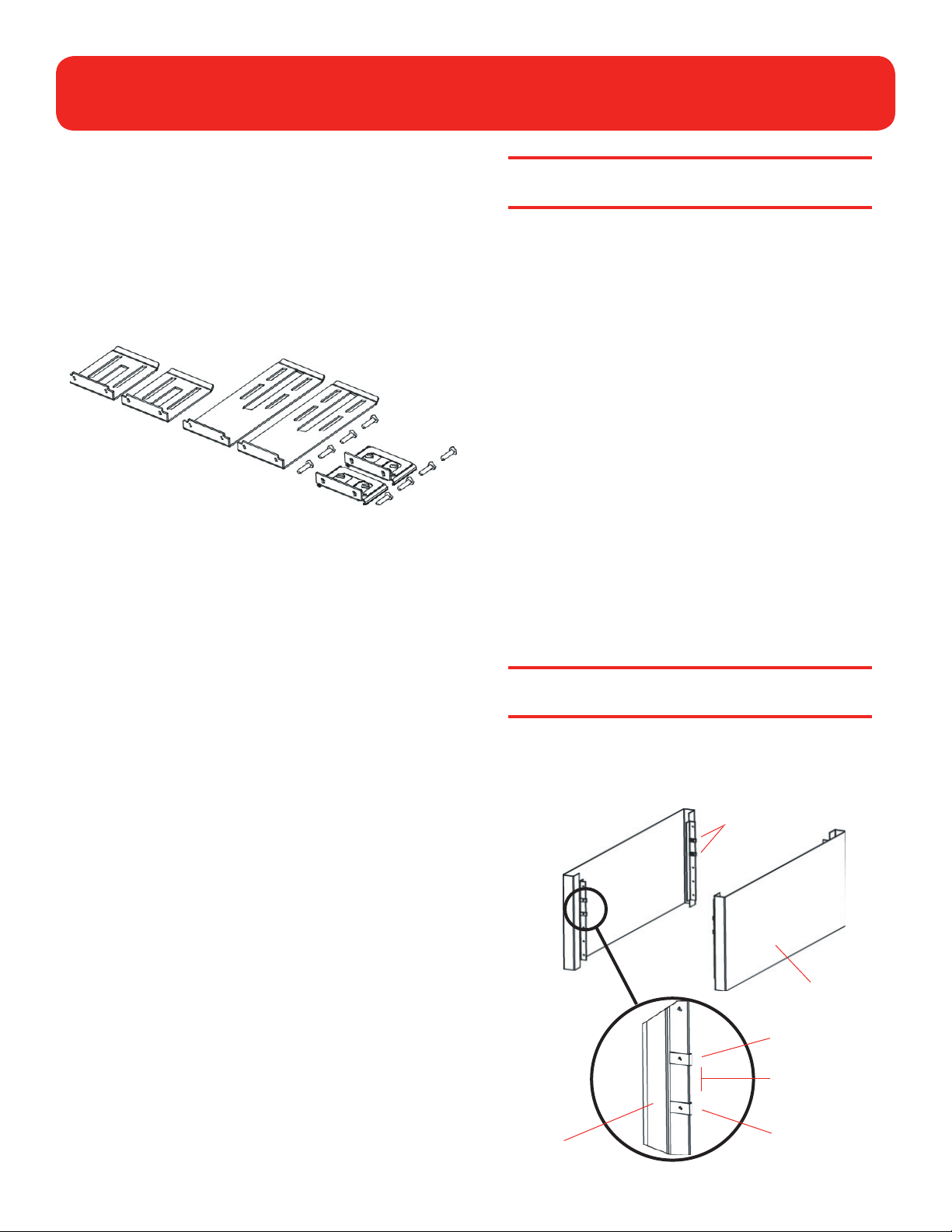
Step 2: Prepare Parts and Tools
a. Check that you have the following parts from the
SuperLoader accessories kit:
• Two short SuperLoader brackets
• Two long SuperLoader brackets
• Two support brackets
• Eight 10-32 x 1/4-inch button head support bracket
screws
Short brackets
Long brackets
Support brackets
and screws
b. Obtain the following items from the accessories kit that
came with your rack:
• Eight clip nuts
• Eight screws
c. Make sure you have the following tools:
• #2 PHILLIPS® screwdriver
• Level
Caution: Excessive dust or other debris in the tape
path can damage tapes and tape drives.
Step 4: Install the SuperLoader in the
Rack
a. Take the following safety precautions for a rack mount
installation:
(1) Lower the rack’s feet.
(2) Extend the rack’s anti-tip device (if available).
(3) Ensure that the rack and all equipment mounted in the
rack have a reliable ground connection.
(4) Verify that the total current of the rack components
(including SuperLoader) will not exceed the current rating
of the power distribution unit or outlet receptacles. For
SuperLoader specifications, refer to the User’s Guide.
(5) Have the help of at least one other person. At least two
people are required to safely install the SuperLoader into
a rack.
Caution: Failure to take these safety precautions may
result in personal injury or equipment damage.
Step 3: Choose a Location for the
SuperLoader
The SuperLoader has the following dimensions:
• Length: 29.67 inches (753.7 mm)
• Width: 17.693 inches (449.4 mm)
• Height: 3.49 inches (88.6 mm)
The SuperLoader is designed to fit in a standard 19-inch rack
using either the long or short brackets (depending on the depth
of the rack).
When selecting a location for the SuperLoader, keep in mind the
following guidelines:
• Minimum clearances of 27 inches (686 mm) in front of
the unit and 17 inches (432 mm) in back are required to
facilitate component removal and installation.
• The SuperLoader should be positioned away from cooling
vents or exhaust from other devices to help minimize the
amount of debris entering the tape path.
b. Install two clip nuts onto each of the four rails of the rack,
spacing the nuts 1.75 inches (44.45 mm) apart at exactly the
same level.
Clip nuts
Rack
outer
cover
Clip nut
1.75 inches
(44.45 mm)
Rail
Clip nut
Page 3
SuperLoader DLT and SuperLoader LTO Quick Start Guide
Page 3
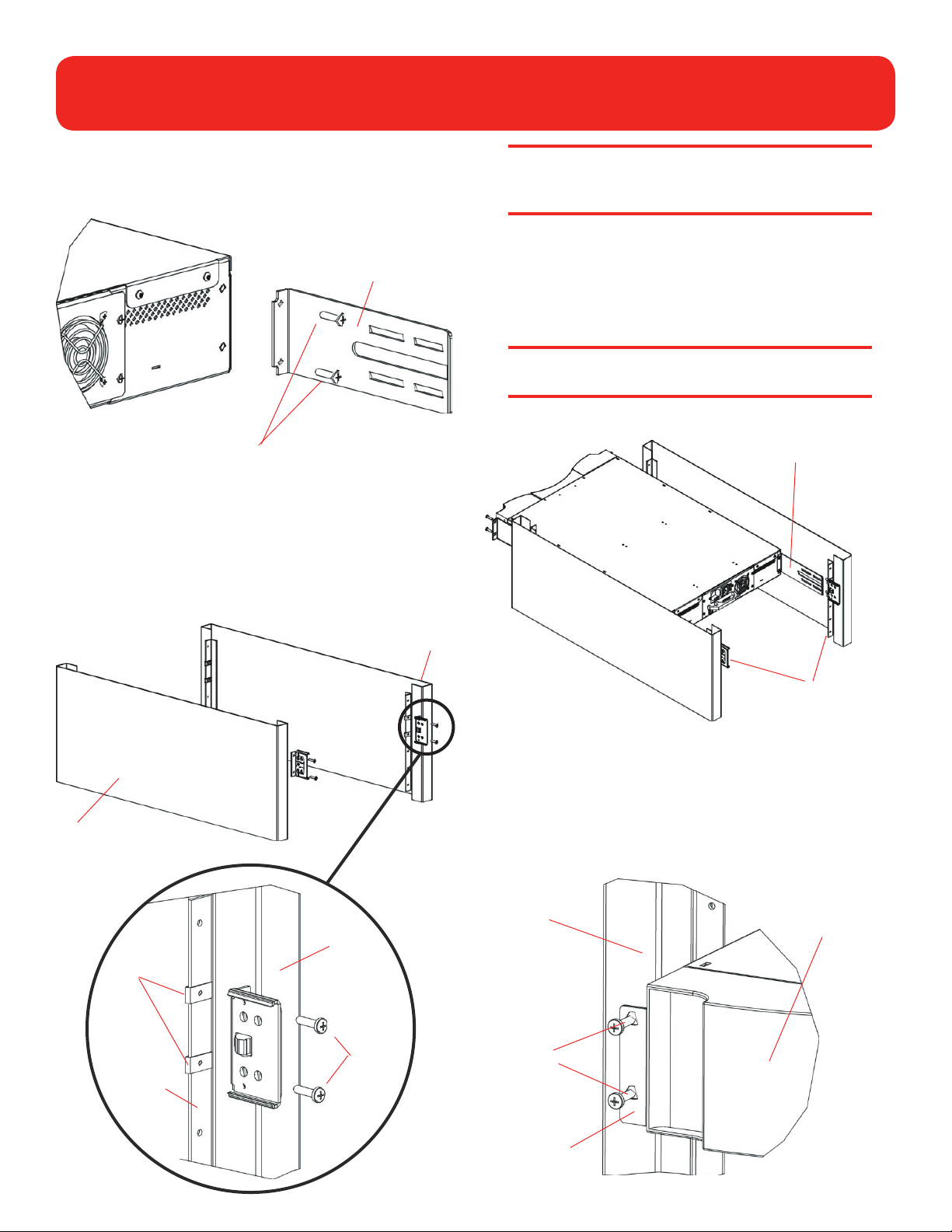
c. Select the long or short SuperLoader brackets (depending
on the depth of the rack) and attach them to the rear of the
SuperLoader on the right and left sides.
Bracket (right side)
Back of SuperLoader
Screws (10-32 x 1/4 only)
d. Using rack screws, attach a support bracket to the clip nuts
on each rear rail. Tighten the screws just enough to hold the
support brackets firmly against the rail while still allowing
the support bracket to be slightly shifted by hand. This
shifting will help facilitate the engagement of SuperLoader
brackets as the SuperLoader is installed in the rack. You will
fully tighten these screws later.
Note: Be sure to attach the support brackets correctly;
the side of the bracket with only two holes should be
secured to the rail.
e. With the help of a second installer, insert the SuperLoader
into the rack so that each SuperLoader bracket slides into the
corresponding support bracket on the rear rails and the tabs
at the front of the SuperLoader align flush with the clip nuts
on the front rails.
Caution: Do not let go of the front end of the
SuperLoader until it can be secured to the rack.
SuperLoader bracket
Rack
Clip nuts
Right
rear rail
Right rear rail
Support
bracket
Rack
screws
Support brackets
f. While the other installer holds the front end of the
SuperLoader, secure the SuperLoader in the rack by doing
the following:
(1) Secure the front end tabs of the SuperLoader to the rack
using four rack screws (two per tab). Make sure the
screws are finger tight.
Left front
rail
Rack
screws
SuperLoader
(front)
Tab (one on
each side)
Page 4

SuperLoader DLT and SuperLoader LTO Quick Start Guide
Page 4
(2) Install four screws (two per side) to secure the support
brackets to the SuperLoader brackets.
SuperLoader bracket
Support bracket
Screws
SuperLoader (back)
Right back rail
g. Verify that the SuperLoader is level. Make installation
adjustments as needed.
h. When the SuperLoader is level, tighten the screws securing
the SuperLoader tabs to the front rails, the SuperLoader
brackets to the support brackets, and the support brackets
to the rear rails.
b. After the cables and terminators are connected properly,
tighten all screws.
VHDCI terminator installed in bottom connection of unit.
Note: Not all terminators have LEDs.
Make sure the terminator is placed on the bottom connector
of the unit and the host cable going to the server is located
at the top, as pictured above.
Note: On all SuperLoaders, SCSI terminators must be
used for proper operation of the drive.
Step 5: Establish the SCSI Connection
a. Make sure the supplied SCSI cable matches the host
computer HBA SCSI input. The host may support VHDCI or
68 pin.
SCSI 68-pin connector
Properly turn off all peripheral devices connected to the host
computer, then properly shut down the host computer.
Note: When connecting SCSI cables, make sure you
correctly align the connector to avoid bending connector
pins.
VHDCI SCSI
VHDCI terminator
Note: Do not turn on the host computer or any
devices connected to the host computer until you have
configured the SuperLoader and installed tape cartridges.
Step 6: Network Connection to the
SuperLoader
Network connection is IP configurable through the front panel
of the SuperLoader.
• DLT models auto negotiate speed of network connection
10/100.
• LTO models can select the network speed from the front
panel under Configuration>10/100.
Connect the network cable to the RJ45 connector found on the
back of the SuperLoader as illustrated on the next page.
Step 7: Power Supply Cable Connection
The power supply cable should be connected to the input power
connection on the back of the SuperLoader as illustrated on the
next page.
Page 5

SuperLoader DLT and SuperLoader LTO Quick Start Guide
Page 5
Power connector
RJ45 connection for Web interface:
Login: guest
Password: guest
Host cable end (can be
VHDCI or 68 pin)
VHDCI connection (host cable
at the top, terminator at the
bottom)
Step 8: Power Up Sequence
Note: Make sure that once the power, SCSI, and network
connections are made, the library is powered up before
the host is booted.
Step 9: Verify Robot/Drive Seen by the
Operating System
Windows 2000:
Under Device Manager, an unknown media changer should
be present. Under Tape Drive, you should see the drive that is
configured for your SuperLoader.
Sun:
During reboot, break the standard initialization and do a
probe scsi all
configured for the unit.
. This should show the SuperLoader and the drive
Step 10: Configuration of the Web
Interface
Obtain the IP address from your network administrator, or the
host DHCP server will provide you the IP address.
Under Configuration>Ethernet on the front panel of the
SuperLoader, enter the appropriate settings for:
• Set IP
• Set Subnet Mask
• Set Gateway
• Set SNMP Server
• Set Time Server
Under Set IP, you can set the unit for DHCP or enter a static IP.
Boot the host computer after ensuring that the SuperLoader
completed initialization without errors. A green LED should be
visible on the LCD screen showing the unit is in the ready state.
During the host computer boot sequence, ensure that the host
adaptor can see all devices.
SCSI RAID adaptors are not suitable for running tape libraries.
On-board SCSI host adaptors have problems with configuration,
and make visibility of the robot and the drive very inconsistent.
Host adaptor requirements:
• LUN support: enabled
• Initiate wide negotiation: enabled
• Sync transfer rate: most tape drives should be set for
80.0 MB/sec
• Robots could be set for 40.0 MB/sec
If the robot cannot be seen during the boot sequence, check the
front panel of the SuperLoader, under Configuration>Change
Mode to make sure that Random is selected.
Once connected, you can enter the IP address in a browser
and go directly to the Home page of the On-board Remote
Management for the SuperLoader.
To use On-board Remote Management, other than the Home
page, you must enter a User name and Password.
• Default User name: guest
• Default Password: guest
Both fields are case sensitive.
Page 6

SuperLoader DLT and SuperLoader LTO Quick Start Guide
Step 11: Load Tape Cartridges
The SuperLoader can hold up to 16 tape cartridges in two
magazines, one installed on the left side and the other installed
on the right side of the SuperLoader. The cartridge slots in the
left magazine are numbered 1 through 8, and the cartridge slots
in the right magazine are numbered 9 through 16.
The SuperLoader can also be shipped with an eight-cartridge
capacity. In this case, a magazine blank is inserted as well.
Note: The SuperLoader will not run unless both magazine
openings are loaded with either a magazine or a
magazine blank.
Page 6
Left magazine
Handle
To load tape cartridges in the SuperLoader:
a. Eject and remove an empty magazine as follows:
(1) At the front panel of the SuperLoader, press Enter.
(2) Scroll to Commands and press Enter.
(3) Scroll to Eject and press Enter.
(4) If you are requested to enter a password, type 000000
(the default password) and press Enter.
(5) Scroll to Left Magazine (or Right Magazine as
appropriate) and press Enter to eject that magazine.
The selected magazine is released.
Caution: To prevent damage to the SuperLoader or
to the magazine, use both hands when removing the
magazine from the SuperLoader.
(6) Grasp the magazine by the handle with one hand and
slide it out while supporting the length of the magazine
from underneath with the other hand (see illustration
following).
Note: If a magazine blank is installed, it does not need to
be ejected. Instead, it can be installed/removed by sliding
it in/out using the handle.
b. Load tape cartridges into the magazine(s).
(1) Using the dials on the magazine, move the slot conveyor
belt within the magazine until a slot lines up with one of
the six openings on the other side of the magazine.
Dial
Right magazine
(right side)
(2) Correctly orient the cartridge for insertion in the slot.
Right magazine
(left side)
Dial
Note: When you eject a magazine, you must fully remove
it, or fully insert it, before turning off the SuperLoader.
(7) To eject and remove the other magazine at this time,
press Escape, then scroll to the other magazine, and
press Enter. Then, repeat step 6.
To remove the other magazine later, repeat this
procedure.
Openings
Tape cartridge
(note orientation)
Openings
(3) Insert the cartridge into the slot. As you push the
cartridge in, you will feel some resistance until the
cartridge latches into the slot.
Page 7

SuperLoader DLT and SuperLoader LTO Quick Start Guide
Note: Each slot has a keying feature that prevents the
cartridge from being inserted incorrectly.
(4) Repeat this procedure until all tape cartridges have been
loaded into the magazine(s).
Note: You can remove a tape cartridge in the same
manner as you inserted it. Use the dials on the magazine
to line up the desired tape cartridge with one of the
openings on the other side of the magazine. Then, using
your thumb and index finger, pull out the cartridge.
You will feel a slight resistance as you begin to pull but
continue to pull until the cartridge comes free.
c. Install the magazine(s) into the SuperLoader.
(1) Grasp the magazine by the handle with one hand and
support it from underneath with your other hand.
Page 7
(2) Position the magazine correctly in the SuperLoader. The
magazine can only be inserted into the SuperLoader in
the correct orientation.
(3) Push the magazine in until it clicks and locks into place.
(4) Repeat this procedure to install the second magazine as
appropriate.
The SuperLoader performs an auto-inventory of the
tape cartridges in the magazine(s). Once completed, the
SuperLoader is ready for normal operation.
Note: These instructions are for both the SuperLoader
DLT and SuperLoader LTO due to the nature of
their similarities. Many component parts are not
interchangeable. These include the magazines, cartridges,
drive carrier assemblies, magazine blanks, magazine
handles, and the bar code scanner. Please order the
appropriate part numbers when replacing these items.
Caution: When removing magazines or blanks, be
certain that no robotic operations are in process.
Failure to do so will stop the robot, and possibly
cause damage.
Page 8

SuperLoader DLT and SuperLoader LTO Quick Start Guide
Page 8
For more information,
visit our Web site at
www.quantum.com
United States of America
Quantum Corporation
Storage Solutions Group
141 Innovation Drive
Irvine, CA 92612
U.S.A.
phone 949.856.7800
Europe
7 Lindenwood
Chineham Business Park
Basingstoke, RG24 8QY
United Kingdom
phone +44 1256 818300
fax +44 1256 848700
Asia Pacific
Level 3
200 Creek Street
Brisbane, Qld 4000
Australia
phone +61 7 3839 0950
fax +61 7 3839 0955
fax 949.856.7799
© 2004 Quantum Corporation. All rights reserved. DLTtape, the DLTtape logo, Quantum, the Quantum logo, SuperDLTtape, the Super DLTtape logo, and SuperLoader are trademarks of
Quantum Corporation registered in the U.S.A. and other countries. Products mentioned herein are for identification purposes only and may be registered trademarks or trademarks of their
respective companies. All other brand names or trademarks are the property of their respective owners.
81-81263-01 A01 Rev. August 2004
6207947-02cN 02
 Loading...