

Page 1

8VHU·V*XLGH8VHU·V*XLGH8VHU·V*XLGH8VHU·V*XLGH8VHU·V*XLGH
70
70
4XDQWXP6XSHU/RDGHU
4XDQWXP6XSHU/RDGHU
6XSHU/RDGHU
70
$
Page 2

Quantum SuperLoader Automated Tape Library User’s Guide, 81-60226-02 01, August 2004, Made in USA.
Quantum Corporation provides this publication “as is” without warranty of any kind, either express or
implied, including but not limited to the implied warranties of merchantability or fitness for a particular
purpose. Quantum Corporation may revise this publication from time to time without notice.
COPYRIGHT STATEMENT
Copyright 2004 by Quantum Corporation. All rights reserved.
Your right to copy this manual is limited by copyright law. Making copies or adaptations without prior
written authorization of Quantum Corporation is prohibited by law and constitutes a punishable violation of
the law.
TRADEMARK STATEMENT
Quantum and the Quantum logo are trademarks of Quantum Corporation, registered in the U.S.A. and other
countries. SuperLoader, DLTtape, and Super DLTtape are trademarks of Quantum Corporation. Products
mentioned herein are for identification purposes only and may be trademarks or registered trademarks of
their respective companies. All other trademarks are the property of their respective owners.
6207947-00cP 153
Page 3

Contents
Preface xix
Chapter 1 Introduction 1
General Description........................................................................................... 1
Front View........................................................................................................... 3
Mailslot......................................................................................................... 3
LCD............................................................................................................... 4
Function Keys..............................................................................................4
Status LEDs.................................................................................................. 5
Power Switch...............................................................................................5
Magazines ....................................................................................................5
Rear View ............................................................................................................ 7
Cooling Fans................................................................................................ 8
AC Power.....................................................................................................8
Ethernet Connection................................................................................... 8
SCSI Connection.......................................................................................... 9
Internal View ...................................................................................................... 9
Picker ..........................................................................................................11
Drive Carrier Assembly (DCA) .............................................................. 11
Bar Code Reader ....................................................................................... 11
Supported Software......................................................................................... 12
SuperLoader User’s Guide iii
Page 4

Contents
Chapter 2 Installation and Configuration 13
Preparation........................................................................................................13
SCSI Bus Requirements ............................................................................14
Accessories .................................................................................................14
Installation Location Requirements........................................................15
Rack Mounting the SuperLoader...................................................................16
General Preparation for Rack Mount Installation................................19
Stationary Rack Mount Installation........................................................19
Making the SCSI Connection..........................................................................26
Powering On the SuperLoader.......................................................................28
Configuration....................................................................................................30
Setting SCSI ID..................................................................................................32
Setting Ethernet ................................................................................................34
IP Address..................................................................................................34
Subnet Mask...............................................................................................37
IP Gateway .................................................................................................38
Setting the SNMP Server..........................................................................39
Setting the Time Server ............................................................................40
Setting the Time................................................................................................42
Setting the Change Mode ................................................................................46
Sequential Mode Operations ...................................................................47
Setting Security .................................................................................................49
Security Option..........................................................................................49
Setting Magazines ............................................................................................50
v20 Firmware and the SuperLoader LTO..............................................51
v45 Firmware and the SuperLoader DLT (excludes DLT1)................51
v45 Firmware and the SuperLoader DLT1............................................51
Passwords..........................................................................................................52
Getting Lost Passwords............................................................................53
Chapter 3 Tape Cartridge Use 55
Tape Cartridges Defined .................................................................................56
Tape Maintenance ............................................................................................59
The Write-Protect Switch ................................................................................59
Tape Drive Cleaning ........................................................................................60
Insert the Cleaning Tape ..........................................................................61
Storing the Cleaning Tape (DLT/SDLT Only) in a Magazine............63
Eject the Cleaning Tape............................................................................64
iv SuperLoader User’s Guide
Page 5

Contents
Tape Drive Cleaning Methods ....................................................................... 65
Manual Cleaning (DLT/SDLT Only)..................................................... 65
Auto Clean................................................................................................. 66
Software...................................................................................................... 67
Chapter 4 SuperLoader Operation 69
Front Panel Components ................................................................................70
Function Keys............................................................................................70
LEDs............................................................................................................ 70
LCD............................................................................................................. 71
Front Panel Menus........................................................................................... 71
Commands Menu ..................................................................................... 74
Status Menu............................................................................................... 74
Configuration Menu................................................................................. 75
Diagnostics Menu ..................................................................................... 75
Front Panel Functionality ............................................................................... 75
Enter Passwords........................................................................................ 75
Logout......................................................................................................... 77
Set Change Mode Settings....................................................................... 77
Using Data Cartridges.............................................................................. 77
Insert a Single Cartridge .......................................................................... 78
Move a Single Cartridge .......................................................................... 80
Eject a Single Cartridge............................................................................80
Use of Magazines and Magazine Blanks ...................................................... 82
Eject a Magazine .......................................................................................82
Install a Magazine..................................................................................... 83
Manually Operate the Magazine............................................................ 84
View Status Information................................................................................. 90
View SuperLoader Status ........................................................................ 90
View Firmware Version........................................................................... 92
View Element Status................................................................................. 92
View Tape Drive Status ........................................................................... 94
View Tape Drive Version ........................................................................95
View Ethernet Information...................................................................... 96
View Flex I/O Information ..................................................................... 97
Run Inventory................................................................................................... 98
Set Data Compression ..................................................................................... 98
Updating the System ....................................................................................... 99
SuperLoader User’s Guide v
Page 6

Contents
On-board Remote Management...................................................................102
Open On-board Remote Management.................................................102
Status Information...................................................................................103
Default Username and Password .........................................................103
Time Display............................................................................................104
Feedback on Pages ..................................................................................104
Commands Page.............................................................................................105
Moving Tapes ..........................................................................................106
Inventory ..................................................................................................106
Set to Home..............................................................................................106
Sequential Operations ............................................................................107
Configurations Page.......................................................................................108
System Operations Options...................................................................109
SCSI ID......................................................................................................109
Set the Mode ............................................................................................111
View the Compression Setting..............................................................112
Set the Cleaning Mode............................................................................113
Set the Magazines....................................................................................113
Set the System Time................................................................................114
Set Networking Options.........................................................................117
Set Security Options................................................................................118
Diagnostics Page.............................................................................................124
Run Diagnostic Tests ..............................................................................124
Identify SuperLoader..............................................................................126
Perform a System Reset..........................................................................127
System Updates Page.....................................................................................127
Perform System Updates .......................................................................127
Chapter 5 Troubleshooting 129
Before Contacting Quantum Support..........................................................129
Contacting Quantum Technical Support....................................................134
Returning Units for Repair............................................................................135
Return Authorization Process ...............................................................135
Policies and Procedures .........................................................................136
Repair Process..........................................................................................138
How to Return the SuperLoader for Service..............................................139
To Pack the SuperLoader ..............................................................................142
Check for Errors..............................................................................................144
vi SuperLoader User’s Guide
Page 7

Contents
SuperLoader Error Logs................................................................................ 146
Screen Display of Hard Error Logs ...................................................... 146
Hard Error Log Display ........................................................................153
Hard Error Log Fields ............................................................................ 155
Error Code Field Description................................................................ 155
Error Code Listing .................................................................................. 158
Tape Drive Error Logs...................................................................................165
Error Log Display ................................................................................... 165
Error Log Information............................................................................ 166
SCSI Check Condition Error Logs ....................................................... 167
Bugcheck Error Logs .............................................................................. 173
Event Error Logs ..................................................................................... 174
A400: Read Error............................................................................................ 176
Cause ........................................................................................................ 178
Suggested Actions ..................................................................................178
A401: Write Error........................................................................................... 179
Cause ........................................................................................................ 181
Suggested Actions ..................................................................................181
A402: Drive Error........................................................................................... 182
Cause ........................................................................................................ 185
Suggested Actions ..................................................................................186
A403: Loader Log........................................................................................... 186
Cause ........................................................................................................ 187
Suggested Actions ..................................................................................187
A404/A405: Calibration................................................................................ 188
Cause ........................................................................................................ 190
Suggested Actions ..................................................................................191
A407: Directory Read .................................................................................... 191
Cause ........................................................................................................ 196
Suggested Actions ..................................................................................196
A408: Directory Write.................................................................................... 197
A500: SDLT Hard Read Error....................................................................... 201
Cause ........................................................................................................ 202
Suggested Actions ..................................................................................203
A501: SDLT Hard Write Error......................................................................203
Cause ........................................................................................................ 205
Suggested Actions ..................................................................................205
A502: SDLT Loader Communication Error................................................ 205
Cause ........................................................................................................ 206
Suggested Actions ..................................................................................206
A503: SDLT Drive-Servo Error..................................................................... 206
Cause ........................................................................................................ 211
Suggested Actions ..................................................................................211
SuperLoader User’s Guide vii
Page 8

Contents
A507/A508: Directory Read Failure/Directory Write Failure ................212
Cause.........................................................................................................218
Suggested Actions...................................................................................219
Chapter 6 Diagnostics 221
POST.................................................................................................................221
POST Descriptions ..................................................................................222
Perform a POST.......................................................................................222
Interpret the POST Results ....................................................................223
Diagnostic Tests..............................................................................................223
Set the Security ........................................................................................223
Stop a Diagnostic Test ............................................................................224
Front Panel Diagnostic Tests .................................................................225
On-board Remote Management Diagnostic Tests.....................................226
Diagnostics Using On-board Remote Management ..........................227
Appendix A Basic Information Logs 229
Log Descriptions......................................................................................229
SuperLoader Logs ..........................................................................................230
Common Information.............................................................................231
Log Display ..............................................................................................231
Log Fields .................................................................................................231
Error Codes ..............................................................................................232
Soft Logs ...................................................................................................236
Update Logs.............................................................................................236
Shadow Event Log ..................................................................................236
Boot Logs..................................................................................................237
OEM Logs.................................................................................................237
ID Logs......................................................................................................237
Tape Drive Logs..............................................................................................238
Common Information.............................................................................238
Log Display ..............................................................................................238
Log Fields .................................................................................................238
POST Failure Logs...................................................................................239
DLT Drive Diagnostic Results Logs .....................................................240
DLT Firmware Changes ........................................................................241
viii SuperLoader User’s Guide
Page 9

Contents
Appendix B Specifications 243
SuperLoader Physical Specifications .......................................................... 244
SuperLoader Performance Specifications................................................... 244
SuperLoader Power Specifications.............................................................. 246
SuperLoader Environmental Specifications............................................... 247
SuperLoader Vibration Specifications ........................................................ 248
SuperLoader Shock Specifications...............................................................248
SuperLoader Product Safety/Compliance................................................. 249
SuperLoader Acoustic and Noise Limits.................................................... 249
SCSI Specifications......................................................................................... 250
SCSI Cable and Terminator Requirements ......................................... 250
SCSI Cable Length .................................................................................. 250
Ethernet ........................................................................................................... 250
Appendix C Time Zones 251
Appendix D Regulatory Statements 255
Taiwan Statement ..........................................................................................256
Japan Notice.................................................................................................... 257
Canadian Notice (Avis Canadien)...............................................................257
European Union Notice ................................................................................257
Product Safety Electrostatic Discharge .......................................................258
Grounding Methods ...................................................................................... 259
Laser Safety..................................................................................................... 259
Taiwan Battery Recycling Label .................................................................. 259
Glossary 261
Index 273
SuperLoader User’s Guide ix
Page 10

Contents
x SuperLoader User’s Guide
Page 11

Figures
Figure 1 LCD Front Panel Screen ..........................................................xxii
Figure 2 On-board Remote Management Screen ...............................xxiii
Figure 3 SuperLoader Front View............................................................. 3
Figure 4 Function Keys ............................................................................... 4
Figure 5 Magazine (left and right sides)...................................................6
Figure 6 Magazine Blank ............................................................................7
Figure 7 SuperLoader DLT Rear View ..................................................... 7
Figure 8 SuperLoader LTO Rear View ..................................................... 8
Figure 9 Internal View of the SuperLoader............................................ 10
Figure 10 Clearance Requirements for Rack Mounting ......................... 18
Figure 11 Required Parts for Installation .................................................20
Figure 12 Installing Two Clip Nuts...........................................................21
Figure 13 Attaching SuperLoader Brackets ............................................. 22
Figure 14 Attaching Support Brackets......................................................23
Figure 15 Sliding SuperLoader into Rack.................................................24
Figure 16 Front Alignment ......................................................................... 25
Figure 17 Connecting Support Brackets ................................................... 25
SuperLoader User’s Guide xi
Page 12

Figures
Figure 18 Making the SCSI Connection ....................................................27
Figure 19 Sample Idle Screen Display (SuperLoader LTO
illustrated) 29
Figure 20 LCD Front Panel .........................................................................30
Figure 21 Submenu for Configuration ......................................................31
Figure 22 Main Menu (LCD).......................................................................33
Figure 23 Configuration Menu (LCD).......................................................33
Figure 24 Main Menu (LCD).......................................................................34
Figure 25 Main Menu (LCD).......................................................................35
Figure 26 Static IP Selection........................................................................36
Figure 27 Main Menu (LCD).......................................................................37
Figure 28 Set Subnet Mask..........................................................................37
Figure 29 Main Menu (LCD).......................................................................38
Figure 30 IP Gateway...................................................................................38
Figure 31 Main Menu (LCD).......................................................................39
Figure 32 Set IP Server.................................................................................40
Figure 33 Main Menu (LCD).......................................................................41
Figure 34 Setting a Time Server..................................................................41
Figure 35 Main Menu (LCD).......................................................................43
Figure 36 Setting a Time Zone (Hours).....................................................43
Figure 37 Setting a Time Zone (Minutes) .................................................44
Figure 38 Main Menu (LCD).......................................................................44
Figure 39 Setting the Date and Time .........................................................45
Figure 40 Main Menu (LCD).......................................................................46
Figure 41 Main Menu (LCD).......................................................................48
Figure 42 Main Menu (LCD).......................................................................48
Figure 43 Main Menu (LCD).......................................................................49
Figure 44 Main Menu (LCD).......................................................................50
Figure 45 Main Menu (LCD).......................................................................52
xii SuperLoader User’s Guide
Page 13

Figures
Figure 46 Password Screen......................................................................... 53
Figure 47 DLTtape IV and Super DLTtape I Cartridges ........................ 57
Figure 48 SDLT II Cartridge ....................................................................... 58
Figure 49 Ultrium Format Tape Cartridge...............................................58
Figure 50 Write-Protect Switch (SDLT Shown) ....................................... 59
Figure 51 Magazine Map ............................................................................ 62
Figure 52 Media Compatibility Chart....................................................... 68
Figure 53 SuperLoader DLT Menu Tree Structure ................................. 72
Figure 54 SuperLoader LTO Menu Tree Structure................................. 73
Figure 55 Log In Sample .............................................................................76
Figure 56 Loading a Cartridge (SDLT Tape Shown) .............................. 79
Figure 57 Installing a Magazine................................................................. 83
Figure 58 Installing a Magazine (continued) ...........................................84
Figure 59 View of Magazines.....................................................................85
Figure 60 Cartridge Orientation (SDLT Shown) ..................................... 86
Figure 61 Upper Slot of Magazine (SDLT Shown).................................. 87
Figure 62 Top of Magazine.........................................................................88
Figure 63 Identifying a Magazine Slot (SDLT Shown)...........................89
Figure 64 LCD Messages............................................................................. 91
Figure 65 Firmware Version Display........................................................ 92
Figure 66 Element Status ............................................................................ 93
Figure 67 Magazine Slot Map .................................................................... 93
Figure 68 Element Status ............................................................................ 94
Figure 69 Tape Drive Status (DLT/SDLT Shown).................................. 94
Figure 70 Tape Drive Version .................................................................... 95
Figure 71 View Ethernet Information ....................................................... 96
Figure 72 View Flex I/O Information (Scrolled Down) ......................... 97
Figure 73 Accessing the Backup Copy of Firmware (SuperLoader
DLT Shown) .............................................................................. 101
Figure 74 On-board Remote Management Home Page ....................... 103
SuperLoader User’s Guide xiii
Page 14

Figures
Figure 75 Feedback in On-board Remote Management Screen ..........104
Figure 76 Commands Page .......................................................................105
Figure 77 Screen for Configurations Page ..............................................108
Figure 78 Systems Operations Page.........................................................109
Figure 79 Screen for Configurations........................................................110
Figure 80 Setting the Mode .......................................................................111
Figure 81 Viewing the Compression Setting..........................................112
Figure 82 Setting the System Time...........................................................116
Figure 83 Setting Network Options.........................................................117
Figure 84 Setting Security Options ..........................................................119
Figure 85 Setting Authorized Client List ................................................121
Figure 86 Disabling Sets ............................................................................122
Figure 87 Setting Client Overlap Control ...............................................123
Figure 88 Diagnostics Page .......................................................................124
Figure 89 View Test Status........................................................................125
Figure 90 Viewing Error or History Logs ...............................................126
Figure 91 System Updates.........................................................................127
Figure 92 Removing the SuperLoader from the Rack...........................140
Figure 93 Loosening the Support Brackets.............................................140
Figure 94 Connecting Support Brackets..................................................141
Figure 95 Removing the Brackets ............................................................142
Figure 96 Shipping Materials....................................................................143
Figure 97 Error Flowchart.........................................................................145
Figure 98 Hard Error Log as Displayed via FTP and On-board
Remote Management ...............................................................153
Figure 99 Hard Error Log as Displayed on Front Panel and SCSI
Formats.......................................................................................154
Figure 100 Error Code Block Descriptor for Hard and Soft Event
Logs.............................................................................................156
Figure 101 Example Tape Drive Error Log...............................................166
xiv SuperLoader User’s Guide
Page 15

Figures
Figure 102 Example DLT1 Tape Drive Error Log ...................................166
Figure 103 SCSI Check Condition Error Log ...........................................168
Figure 104 Bugcheck Error Log..................................................................173
Figure 105 Event Error Log ........................................................................ 175
Figure 106 Read Error Block Descriptor...................................................176
Figure 107 Write Error Block Descriptor.................................................. 179
Figure 108 Drive Error Block Descriptor .................................................. 182
Figure 109 32-Bit Register ........................................................................... 185
Figure 110 Loader Error Field Descriptions............................................. 186
Figure 111 Calibration Block Descriptor .................................................. 188
Figure 112 Directory Read Block Descriptor............................................ 192
Figure 113 Directory Write Block Descriptor........................................... 197
Figure 114 Hard Read Error/Hard Write Error Block Descriptor ....... 201
Figure 115 Hard Read Error/Hard Write Error Block Descriptor ....... 203
Figure 116 Loader Communication Error Block Description................ 205
Figure 117 Drive Servo Error Block Descriptor....................................... 206
Figure 118 Directory Read Failure/Write Failure Block
Descriptor .................................................................................. 212
Figure 119 Log Display ............................................................................... 231
Figure 120 Error Code Block Descriptor for Hard and Soft Event
Logs ............................................................................................ 232
Figure 121 Shadow Event Log ...................................................................237
Figure 122 Example Tape Drive Log......................................................... 238
Figure 123 POST Failures Event Log ........................................................240
Figure 124 DLT Drive Diagnostics Event Log .........................................241
SuperLoader User’s Guide xv
Page 16

Figures
xvi SuperLoader User’s Guide
Page 17

Tables
Table 1 LCD Panel Function Keys ........................................................... 5
Table 2 Location Criteria......................................................................... 15
Table 3 UL Criteria................................................................................... 16
Table 4 Write-Protect Switch Positions.................................................60
Table 5 LED Display ................................................................................ 70
Table 6 SuperLoader Status .................................................................... 91
Table 7 Firmware Version Description ................................................. 92
Table 8 Tape Drive Status ....................................................................... 95
Table 9 Tape Drive Version .................................................................... 96
Table 10 Ethernet Information Messages................................................ 97
Table 11 Flex I/O Information .................................................................97
Table 12 Suggested Actions for Performance Problems..................... 130
Table 13 Screen Display of Hard Error Logs........................................ 146
Table 14 Hard Error Log Fields.............................................................. 155
Table 15 Error Code Field Descriptions................................................ 156
Table 16 Error Code Listing.................................................................... 158
Table 17 Tape Drive Field Descriptions................................................ 167
SuperLoader User’s Guide xvii
Page 18

Tables
Table 18 SCSI Check Condition Error Log Field Descriptions ..........168
Table 19 Sense Key Field Definitions.....................................................169
Table 20 ASC/ASCQ Field Description ................................................171
Table 21 Bugcheck Log Field Descriptions...........................................174
Table 22 Event Error Log Field Descriptions........................................175
Table 23 Read Error Field Descriptions.................................................177
Table 24 Write Error Field Descriptor ...................................................180
Table 25 Drive Error Log Field Descriptions........................................183
Table 26 Loader Error Field Descriptions .............................................187
Table 27 Calibration Field Descriptions................................................188
Table 28 Directory Read Field Descriptions .........................................193
Table 29 Directory Write Field Descriptions ........................................198
Table 30 Hard Read Error/Hard Write Error Field Descriptions .....202
Table 31 Hard Read Error/Hard Write Error Field Descriptions .....204
Table 32 Loader Communication Error Field Description.................205
Table 33 Drive Servo Error Field Descriptions.....................................207
Table 34 Directory Read Failure/Write Failure Field Descriptions..213
Table 35 POST Descriptions....................................................................222
Table 36 Log Retrieval Methods.............................................................230
Table 37 Basic Information (SuperLoader) Log Fields........................232
Table 38 Error Code Field Descriptions ................................................233
Table 39 Tape Drive Field Descriptions ................................................239
Table 40 POST Failures Event Log Field Description .........................240
Table 41 DLT Drive Diagnostics Field Descriptions ...........................241
Table 42 Times and Time Zones.............................................................252
xviii SuperLoader User’s Guide
Page 19

Preface
This chapter describes this guide’s audience, purpose, organization,
document conventions, and product safety.
Note: Due to the nature of their similarities, this manual is for the
SuperLoader™ DLT™, the SuperLoader SDLT™, the
SuperLoader LTO-1, and the SuperLoader LTO-2. Many
component parts are not interchangeable. These include the
magazines, cartridges, drive carrier assembly, magazine blank,
magazine handle, and the bar code scanner. Please order the
appropriate part numbers when replacing these items.
Refer to the appropriate Quick Start reference guide for
instructions on Customer-Replaceable Units (see Related
Quantum Documentation on page xxi).
Audience This user manual is designed and written for end users and field service
engineers.
SuperLoader User’s Guide xix
Page 20

Preface
Purpose The purpose of this manual is to provide end users with the following
information:
• SuperLoader description and specifications
• SuperLoader installation and configuration
• Tape cartridge description and general overview
• SuperLoader operation
• Troubleshooting
Document
Organization
This manual is organized as follows:
• Chapter 1, Introduction
- This chapter provides a general overview of
the SuperLoader’s components and functionality.
• Chapter 2, Installation and Configuration
- This chapter describes
how to unpack, install, configure, remove, and repack the
SuperLoader.
• Chapter 3, Tape Cartridge Use
- This chapter describes tape cartridge
care and usage.
• Chapter 4, SuperLoader Operation
- This chapter describes the
components of the SuperLoader, setting passwords, setting modes,
loading cartridges, installing magazines, and testing the
SuperLoader’s functionality.
• Chapter 5, Troubleshooting
- This chapter describes how to
determine and repair minor and major problems that may occur in
the SuperLoader. It also contains information relating to the error and
event logs.
• Chapter 6, Diagnostics
- This chapter describes the Power-On Self
Test (POST) and diagnostic tests for testing the SuperLoader’s
functionality and for troubleshooting errors.
• Appendix A, Basic Information Logs
- This appendix describes the
logs for the SuperLoader and tape drives. It contains a description of
each log type including log block descriptor and field descriptions.
• Appendix B, Specifications
- This appendix describes the
SuperLoader’s specifications.
• Appendix C, Time Zones
- This appendix provides a listing of Time
Zones for setting the time on the SuperLoader.
xx SuperLoader User’s Guide
Page 21

• Appendix D, Regulatory Statements - This appendix provides
required regulatory statements for the SuperLoader.
Preface
Related
Documentation
Documents related to the Quantum SuperLoader are shown below:
Related Quantum Documentation
Document No. Document Title Document Description
81-81263
Quantum
SuperLoader Quick
Start Guide
This guide contains a
sequence of steps
recommended for unpacking,
installing, and setting up
your SuperLoader.
81-81264
81-81265
81-81266
Quantum
SuperLoader Drive
Carrier Assembly
(DCA) Quick Start
Guide
Quantum
SuperLoader
Magazine Quick
Start Guide
Quantum
SuperLoader Bar
Code Reader Quick
Start Guide
This guide contains a
sequence of steps
recommended for unpacking
and installing a DCA.
This guide contains a
sequence of steps
recommended for unpacking
and installing a magazine.
This guide contains a
sequence of steps
recommended for unpacking
and installing a bar code
reader.
0
81-81267
81-81237
Quantum
SuperLoader Slide
Rail Kit Quick Start
Guide
How to Ship the
SuperLoader
This guide contains a
sequence of steps
recommended for unpacking
and installing a slide rail kit.
This guide provides
information on the proper
packing for returning the
SuperLoader for repair.
SuperLoader User’s Guide xxi
Page 22
Preface
Notational
Conventions
LCD Screen Shots Screen shots for the front panel LCD appear as follows:
Figure 1 LCD Front
Panel Screen
This manual uses the following conventions to designate specific
elements:
Note: Notes emphasize important information related to the main
topic.
Caution: Cautions indicate potential hazards to equipment and are
included to prevent damage to equipment.
Warning: Warnings indicate potential hazards to personal safety
and are included to prevent injury.
Status
Commands
Configuration
Diagnostics
xxii SuperLoader User’s Guide
Page 23
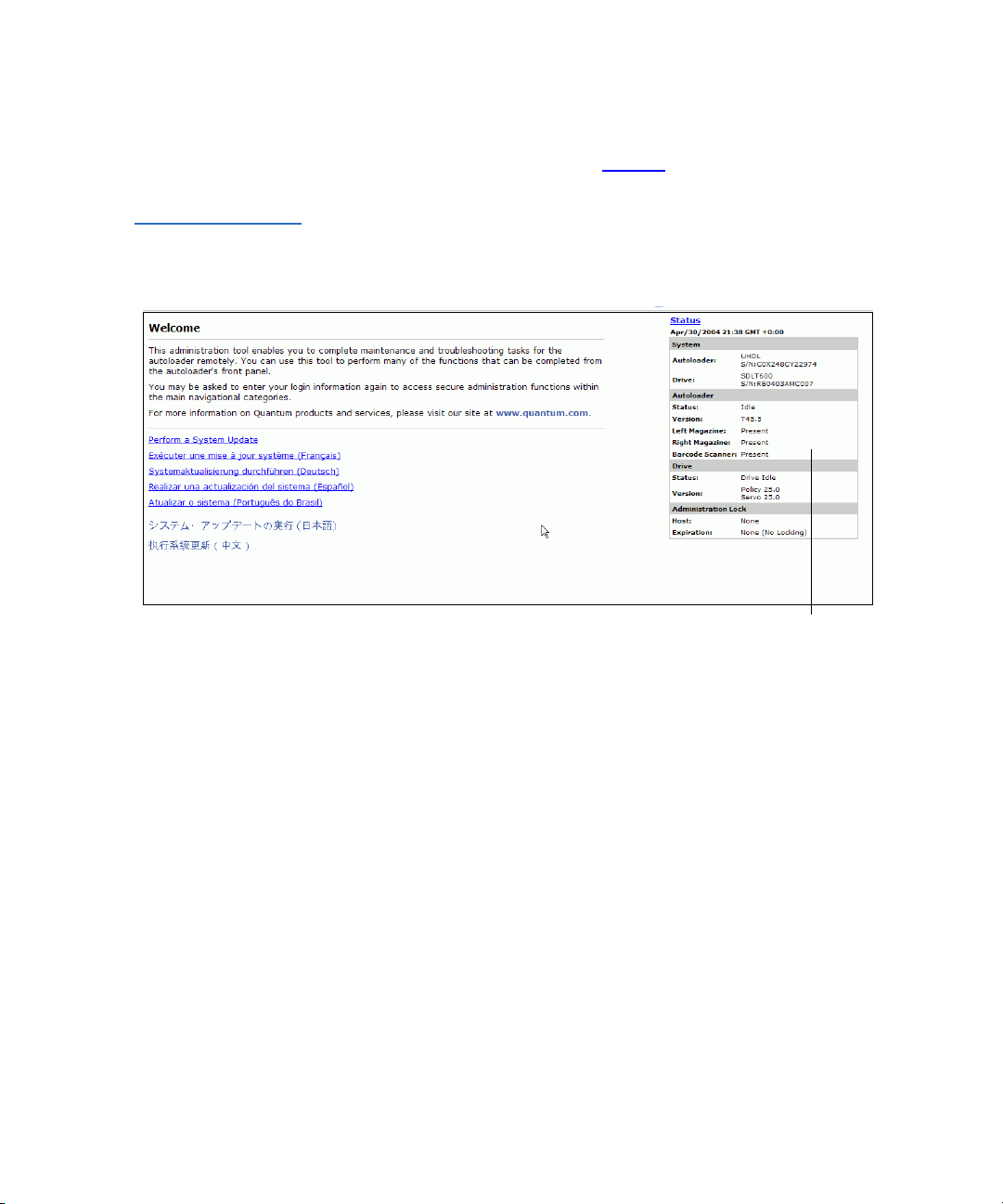
Figure 2 On-board
Remote Management
Screen
Screen shots for On-board Remote Management sometimes contain
callouts and appear as shown in figure 2
.
Preface
Status Information
SCSI-2 Specification 0
The SCSI-2 communications specification is the proposed American
National Standard for information systems, dated March 9, 1990. Copies
may be obtained from:
Global Engineering Documents
15 Inverness Way, East
Englewood, CO 80112
(800) 854-7179 or (303) 397-2740
SuperLoader User’s Guide xxiii
Page 24

Preface
Contact Information
This section provides contact information for worldwide customer
support.
Quantum
To order documentation for the Quantum SuperLoader or other products
contact:
Quantum Corporation
P.O. Box 57100
Irvine, CA 92619-7100
(949) 856-7800
(800) 284-5101
Technical Publications 0
To comment on existing documentation, send e-mail to:
doc-comments@quantum.com
Visit the Quantum home p age at: 0
http://www.Quantum.com
Customer Support 0
0
The Quantum Customer Support Department provides a 24-hour help
desk that can be reached at:
North/South America (949) 725-2100 or
Asia/Pacific Rim (International Code)
Europe/Middle East/Africa: (International Code)
xxiv SuperLoader User’s Guide
(800) 284-5101
+61 7 3839 0988
+44 (0) 1256 848748
Page 25

Send faxes for the Customer Support Department to:
North/South America (949) 725-2176
Asia/Pacific Rim (International Code)
+61 7 3839 0955
Europe/Middle East/Africa: (International Code)
+44 (0) 1256 848777
Send e-mail for the Customer Support Department to:
North/South America www.quantum.com/askaquestion
Asia/Pacific Rim apachelp@quantum.com
Europe/Middle East/Africa: eurohelp@quantum.com
Preface
SuperLoader User’s Guide xxv
Page 26

Preface
xxvi SuperLoader User’s Guide
Page 27

Chapter 1
1Introduction
This chapter describes the SuperLoader components and functionality.
General Description 1
Data backup is essential to protect irreplaceable information. Backing up
data to magnetic tape is an easy, cost-efficient method used by many
small and medium sized businesses. However, most enterprises have so
much data that a single backup tape is not enough; the information has to
be spread across numerous tapes. To avoid constantly changing tapes
manually, many tape backup systems include a SuperLoader.
Each SuperLoader is a robot that includes a tape drive and one or two
magazines for tape cartridges. The user’s application can automatically
load and unload tape cartridges as required for data backup or data
retrieval. SuperLoaders provide compact, high capacity, but low cost
method for simple, unattended data backup.
SuperLoader User’s Guide 1
Page 28

Chapter 1 Introduction
General Description
The SuperLoader contains either the DLT1, SDLT 220, SDLT 320,
SDLT 600, HP LTO-1, or HP LTO-2 tape drive, and one or two magazines
containing up to eight cartridges each. A single cartridge can be inserted
directly via a password-protected mailslot. The cartridge inserts directly
into the tape drive provided there is no cartridge already in the drive, or
you can load the cartridge into a magazine slot provided there is no
cartridge already in the slot.
Note: Throughout this manual, SuperLoaders containing the DLT1,
SDLT 220, SDLT 320, or SDLT 600 tape drives are referred to
as
SuperLoader DLT
. For those SuperLoaders containing
HP LTO-1 or HP LTO-2 tape drives, they are referred to as
SuperLoader LT O
common to all variants, the reference will be
. In instances where the information is
SuperLoader
.
The front panel on the SuperLoader includes a liquid crystal display
(LCD) screen and four function keys. A scrolling menu on the LCD screen
allows you to obtain information from the SuperLoader and enter
commands. The front panel also includes two light emitting diodes
(LEDs) indicating the SuperLoader’s ready status and error status.
The SuperLoader connects to your host server via a SCSI connection
allowing the host to send data and commands automatically. You can
also connect to the SuperLoader using an Ethernet connection to perform
administrative functions and download system updates.
2 SuperLoader User’s Guide
Page 29

Chapter 1 Introduction
Front View
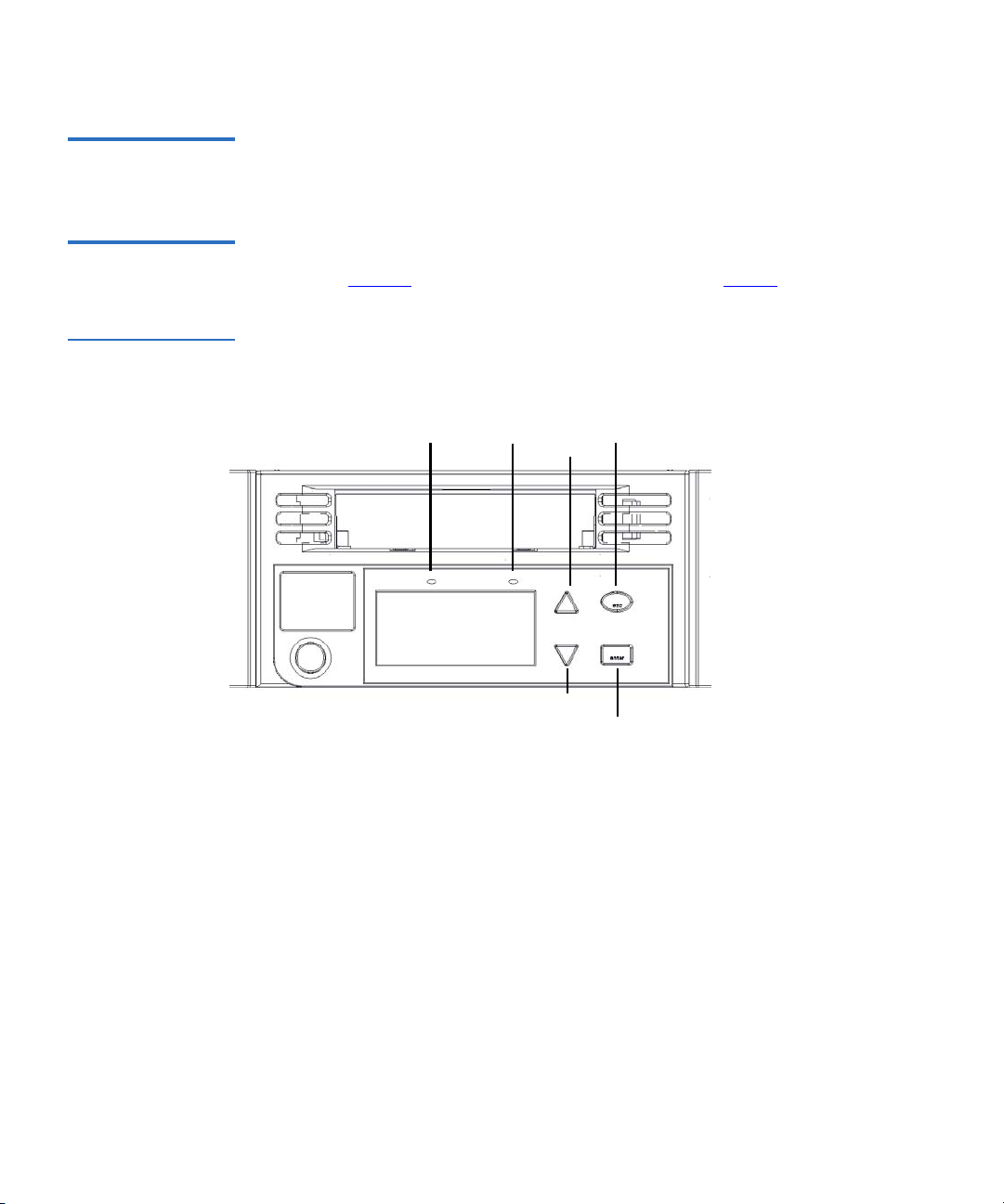
Front View 1
The mailslot, LCD, function keys, status LEDs, power switch, and left and
right magazines are visible on the front panel of the SuperLoader (see
figure 3
Figure 3 SuperLoader
Front View
).
Mailslot
Left magazine/blank
Power switch
Status LEDs
LCD 4 Function keys
Right magazine/blank
Mailslot 1 The SuperLoader has a manual entry port, the mailslot, which you can
use to load or unload a single cartridge. To maintain security, the mailslot
can be password protected. You can insert a cartridge in the mailslot even
if both magazines are completely filled, so long as the tape drive itself is
empty. You can also pass a tape cartridge from the mailslot to the
magazine if the drive is full but the magazine is not.
Note: You should run an inventory from the host application after
using the mailslot. The mailslot is not directly available from
the host application.
SuperLoader User’s Guide 3
Page 30
Chapter 1 Introduction
Front View
LCD 1 The LCD allows you to use the scrolling menu to perform diagnostics and
to enter commands.
Function Keys 1 The function keys allow scrolling through menus to make selections as
shown in figure 4
Figure 4 Function
Keys
. These function keys are described in table 1.
Ready LED
Fault LED
Scroll down
Escape
Scroll up
Enter
4 SuperLoader User’s Guide
Page 31

Chapter 1 Introduction
Front View
Table 1 LCD Panel
Function Keys
Status LEDs 1 The status LEDs show SuperLoader and drive status information. The
Power Switch 1 The power switch is a soft key, which means that if the SuperLoader is
Function Key Description
Enter
Escape
(Scroll Up)
(Scroll Down)
green
Ready LED shows ready status information, and the amber Fault
LED shows fault status information. A solid
and a blinking
moving any cartridges when you press the power switch, it finishes
moving them before powering off. Any other functions, such as writing
to a tape or performing a diagnostic, are interrupted and terminated
when you press the power switch. However, the SuperLoader attempts to
write cached data to tape before the unit powers down.
Fault LED indicates a need for attention.
Press to select an option
Press to return to the previous
menu, to move backwards on a
screen, or to abort an operation
Press to move up through a menu
or through the menu settings
Press to move down through a
menu or through the menu
settings
Fault LED indicates an error,
Magazines 1 The SuperLoader is equipped with one or two cartridge magazines (see
figure 5
accommodates up to eight cartridges. If your SuperLoader contains only
one magazine, a magazine blank is installed in the other magazine bay.
The handles on magazines and magazine blanks are removable and allow
you to configure any magazine or magazine blank to fit in either the left
or the right magazine bay.
The magazines store the tape cartridges and can also store the cleaning
cartridge. The magazines also contain the part of the robotics that moves
the cartridges inside the SuperLoader.
). The magazines are removable and each magazine
SuperLoader User’s Guide 5
Page 32

Chapter 1 Introduction
Front View
Figure 5 Magazine
(left and right sides)
Use one of these knobs to
manually rotate the magazine
when you load and unload
cartridges.
The SuperLoader DLT and
SuperLoader LTO
magazines, magazine
blanks, and magazine
handles are not
interchangeable. The
SuperLoader LTO magazine
displays the LTO Ultrium
logo on the handle.
6 SuperLoader User’s Guide
Page 33

Chapter 1 Introduction
Rear View
Figure 6 Magazine
Blank
Rear View 1
The fans and connection ports are visible on the back of the SuperLoader
as illustrated in figure 7
SuperLoader LTO.
for SuperLoader DLT, and in figure 8 for
Figure 7 SuperLoader
DL T Rear View
Power supply
cooling fan
AC power System cooling fan
Ethernet connection
SCSI connector
SuperLoader User’s Guide 7
AC power
switch
Page 34

Chapter 1 Introduction
Rear View
Figure 8 SuperLoader
LTO Rear View
Power supply
cooling fan
connection
AC Power
AC power switch
System cooling fan
EthernetSCSI
connection
Cooling Fans 1 The SuperLoader has a system cooling fan, plus a second fan to cool the
power supply. These fans maintain the acceptable temperature range for
the tape drive path and all internal electronics. See appendix B
on
page 243 for details about required specifications.
AC Power 1 The SuperLoader requires a nominal voltage in the range of 110 volts AC
to 220 volts AC to operate.
Ethernet Connection 1
The SuperLoader’s Ethernet connection allows you to connect the
SuperLoader to a network, enabling remote administration. The
SuperLoader can also connect to an Simple Network Management
Protocol (SNMP) server and a time server.
The Ethernet connection supports HyperText Transfer Protocol (http).
You can download system updates and perform administrative tasks,
including diagnostics, using http, such as with a Web browser.
8 SuperLoader User’s Guide
Page 35

Chapter 1 Introduction
Internal View
SCSI Connection 1 A low-voltage differential (LVD) SCSI connection links the SuperLoader
to the external host server. LVD connections allow you to have more
devices and longer cable lengths than single ended (SE) SCSI connections.
The LVD SCSI connection uses an 0.8 mm offset Very High Density
(VHD) connector.
Internal View 1
Figure 9
picker sits behind the front panel and mailslot, and can “put” and “get”
cartridges to/from the mailslot, magazines, and tape drive. The drive
carrier assembly (DCA) contains the tape drive, internal power supply,
and cooling fan, and can be removed and replaced as a single component.
shows how the components of the SuperLoader fit together. The
SuperLoader User’s Guide 9
Page 36

Chapter 1 Introduction
Internal View
Figure 9 Internal View
of the SuperLoader
Picker with
misinsertion feature
and turret spreader
Bar code reader bay
DCA
Magazine
Mailslot
Picker Magazine blank
Note: Due to the nature of their similarities, unless noted otherwise,
these illustrations are for the SuperLoader DLT and the
SuperLoader LTO. Many component parts are not
interchangeable. These include the magazines, cartridges,
drive carrier assembly, magazine blank, magazine handle, and
the bar code scanner. Please order the appropriate part
numbers when replacing these items.
10 SuperLoader User’s Guide
Page 37

Chapter 1 Introduction
Internal View
Picker 1 The picker is the component of the SuperLoader that shuttles cartridges
between the drive, both magazines, and the mailslot. It has two degrees
of freedom: rotation and translation. The rotation axis positions the
picker platform in front of each location while the translation axis moves
cartridges on and off of the picker platform. By combining these two
degrees of freedom, a pin on the translation axis engages and disengages
a notch on the right side of the cartridge for pushing and pulling the
cartridge on and off of the platform.
Drive Carrier Assembly (DCA) 1
The DCA is configured with either a DLT1, SDLT 220, SDLT 320,
SDLT 600, HP LTO-1, or HP LTO-2 tape drive. The DCA facilitates easy
removal of the drive. To change tape drives, you can replace the DCA
without having to remove the top cover of the SuperLoader. The
SuperLoader LTO DCA is not interchangeable with the SuperLoader DLT
or SDLT DCA. For further information, refer to the
Carrier Assembly (DCA) Quick Start Guide
.
SuperLoader Drive
Bar Code Reader 1 Since the bar code reader is optional, your SuperLoader may be equipped
with a bar code reader when you receive it, or you may decide to install
one later. The bar code reader provides inventory feedback to the host
application and/or LCD panel/On-board Remote Manager by reading
the cartridge bar code labels. A full 16-cartridge inventory scan may take
up to 90 seconds. The SuperLoader DLT bar code reader and the
SuperLoader LTO bar code reader are
information, refer to the
SuperLoader Bar Code Reader Quick Start Guide
not interchangeable. For further
.
SuperLoader User’s Guide 11
Page 38

Chapter 1 Introduction
Supported Software
Supported Software 1
The SuperLoader is compatible with most operating systems such as:
•NetWare
•Windows® 2000
•Windows
•Windows
• Windows Server™ 2003
•Novell
• Solaris™
•HP-UX
•Linux® (Red Hat®, SuSe®, Caldera™, and TurboLinux®)
•AIX™
The SuperLoader is also compatible with most popular backup software
applications, including:
• CAI ARCserve
®
®
2003
®
XP
®
®
®
•VERITAS™ NetBackup™
• VERITAS BackupExec™
•IBM
•LEGATO Networker
®
Tivoli® Storage Manager
®
Note: Please check with your operating system supplier and your
backup software vendor to verify which version is required for
this SuperLoader.
12 SuperLoader User’s Guide
Page 39

Chapter 2
2Installation and Configuration
This chapter describes how to rack mount and configure the
SuperLoader.
Preparation 2
Before you install your new SuperLoader, unpack it carefully and inspect
it for any damage that might have occurred during shipping. The
SuperLoader Quick Start Guide
necessary information to unpack and inspect your SuperLoader correctly.
Please locate the
SuperLoader Quick Start Guide
included in the packaging describes all the
and follow the directions.
Ensure that the work area is free from conditions that could cause
electrostatic discharge (ESD). Discharge static electricity from your body
by touching a known grounded surface, such as your computer’s metal
chassis.
SuperLoader User’s Guide 13
Page 40

Chapter 2 Installation and Configuration
Preparation
SCSI Bus Requirements 2
You must connect the SuperLoader to one of the following SCSI bus
types:
•Wide, SCSI-2, LVD
•SE SCSI bus
Note: The SuperLoader is not compatible with a High-Voltage
Differential (HVD) SCSI bus.
Your SCSI host adapter card must also support the SCSI bus type used to
connect the SuperLoader. If you use a LVD SCSI bus, use a host adapter
card with a connection for the VHDCI cable.
Note: If you use an SE SCSI bus, the tape drive’s performance is
limited to the maximum data transfer speed of the bus.
Note: The maximum number of SuperLoaders supported per SCSI
bus is four.
Note: The SuperLoader may not work with multiple SCSI LUNS
when attached to a RAID controller. The SuperLoader is not
recommended for use with a RAID controller. If this problem
occurs, it is recommended that the SuperLoader be attached to
a separate SCSI bus controller on the host or server.
Accessories 2 The following accessories are shipped with each SuperLoader:
• Quick Start Guide
• SCSI host cable
•SCSI terminator
• Hardware to rack mount the SuperLoader
• One magazine blank
•Power cable
• Documentation CD containing all of the documentation in Adobe
Portable Document Format (PDF)
14 SuperLoader User’s Guide
®
Page 41

•Bar code labels
Chapter 2 Installation and Configuration
Preparation
Installation Location Requirements 2
Table 2 Location
Criteria
The SuperLoader is designed to fit in a standard 19-inch rack using either
the long or short brackets (depending on the depth of the rack) or the
optional slide rail kit. When choosing an installation location, make sure
that it meets the criteria found in table 2
and table 3.
Requirement Description
Rack Size Standard 19 inch
Room Temperature 10 to 35 degrees C
(50 to 95 degrees F)
Power Source Line frequency: 50 to 60 Hz
Air Quality Good air quality with minimal sources of particulate
contamination. Avoid placing the SuperLoader near
cooling or exhaust vents, printing machines, frequently
used doors and walkways, stacks of supplies that collect
dust, and smoke-filled rooms.
Caution: Excessive dust or other debris in the tape path
can damage tape and tape drives.
Humidity 20% to 80% relative humidity (non-condensing)
Minimum Clearance (to Facilitate
Component Removal and
Installation)
Front:
27.0 in. (686 mm), including 2.0 in. (51 mm) from the
front mounting rail to the inside of the front door.
Rear:
17.0 in. (432 mm). Using the appropriate
SuperLoader bracket, ensure the rear door closes (see
figure 10
).
Proximity to the Host Computer The SCSI bus maximum length is 39.37 ft. (12 m) including
all SCSI bus lengths within the SuperLoader. The SCSI bus
lengths are 16 in. (406.4 mm) per SuperLoader DLT/SDLT
or 23.5 in. (596.9 mm) per SuperLoader LTO.
SuperLoader User’s Guide 15
Page 42

Chapter 2 Installation and Configuration
Rack Mounting the SuperLoader
Table 3 UL Criteria
General Hazards
Elevated Operating Ambient
Temperature
Reduced Air Flow Installation of the equipment in a rack should be such that
Mechanical Loading Mounting of the equipment in a rack should be such that a
Circuit Overloading Consideration should be given to the connection of the
Reliable Earthing (Grounding) Reliable earthing of rack-mounted equipment should be
When installed in a closed or multi-unit rack assembly, the
operating ambient temperature of the rack environment
may be greater than the room ambient. Therefore,
consideration should be given to installing the equipment in
an environment compatible with the manufacturer’s
maximum recommended ambient (TMRA).
the amount of air flow required for safe operation of the
equipment is not compromised.
hazardous condition is not achieved due to uneven
mechanical loading.
equipment to the supply circuit and the effect that
overloading of circuits might have on overcurrent
protection and supply wiring. Appropriate consideration of
equipment nameplate ratings should be used when
addressing the concern.
maintained. Particular attention should be given to supply
connections other than direct connections to the branch
circuit, such as use of power strips.
Rack Mounting the SuperLoader 2
The SuperLoader can be rack mounted in two ways:
• Attached directly to the cabinet rails (stationary)
• Attached to an optional slide rail kit (removable)
16 SuperLoader User’s Guide
Page 43

Chapter 2 Installation and Configuration
Rack Mounting the SuperLoader
Only the stationary installation is included in this manual.
Note: To mount the SuperLoader on the slide rail, refer to the
SuperLoader Slide Rail Kit Installation Quick Start Guide
with the optional shelf assembly. The
Installation Quick Start Guide
Documentation CD or at
is also available on the
www.Quantum.com.
SuperLoader Slide Rail Kit
shipped
SuperLoader User’s Guide 17
Page 44

Chapter 2 Installation and Configuration
Rack Mounting the SuperLoader
Figure 10 Clearance
Requirements for
Rack Mounting
Minimum clearance to load
or unload a magazine from
the system
27.0” [686 mm]
Minimum clearance to load
a tape via the mailslot
Clearance to door inside a rack
2.0” [51 mm]
Minimum side
clearance (both
sides)
1.0” [25 mm]
FRONT
REAR
6.0” [152 mm]
Minimum clearance
between the rear of the
SuperLoader and the
inside of the rack (using
standard mounting
brackets adjusted to their
closest setting)
3.4” [86 mm]
18 SuperLoader User’s Guide
Page 45

Chapter 2 Installation and Configuration
Rack Mounting the SuperLoader
General Preparation for Rack Mount Installation 2
Take the following general safety steps before beginning either rack
mount installation.
1 Lower the cabinet feet.
2 Extend the cabinet anti-tip device, if available.
3 Ensure that the cabinet and all rack mounted equipment have a
reliable ground connection.
4 Verify that the total current of all rack mounted components
(including the SuperLoader) will not exceed the current rating of the
power distribution unit or outlet receptacles.
5 Secure the help of at least one other person. At least two people are
required to safely install the SuperLoader into a rack cabinet.
Warning: Failure to take these safety steps may result in
personal injury or equipment damage.
Caution: Do not remove the top cover of the SuperLoader
during the installation process. Removing the top
cover could result in damage to the SuperLoader.
Stationary Rack Mount Installation 2
This section describes the steps for attaching the SuperLoader directly to
the rails of a rack.
1 Make sure you have the following tools and parts:
• #2 PHILLIPS
®
screwdriver
• Level
• The following SuperLoader accessory kit parts (see figure 11
):
• Four SuperLoader brackets (two long and two short to
accommodate different rack depths)
Use the short SuperLoader brackets (74-60604-03) unless the
distance from the front mounting rail to the rear mounting
rail is less than 30.25 in. (76.84 cm).
• Two support brackets (74-60605-01)
• Eight 10-32 x 1/4 inch button head screws for the support
brackets (four per support bracket)
SuperLoader User’s Guide 19
Page 46

Chapter 2 Installation and Configuration
Rack Mounting the SuperLoader
• The following parts shipped with the rack:
• Eight clip nuts
•Eight screws
Figure 11 Required
Parts for Installation
Short SuperLoader
brackets (74-60604-03)
Support brackets
(74-60605-01)
Long SuperLoader
brackets (74-60604-01)
Support bracket screws
2 Install two clip nuts, 1.75 in. (44.45 mm) apart, onto each of the four
rails of the rack, making sure that you install each pair of clip nuts at
exactly the same level (see figure 12
).
20 SuperLoader User’s Guide
Page 47

Figure 12 Installing
Two Clip Nuts
Chapter 2 Installation and Configuration
Rack Mounting the SuperLoader
Rail
Outer covers
of the rack
Rail
Clip nut
1.75 in
(44.45 mm)
Rail
Clip nut
3 Select the long or short SuperLoader brackets (depending on the
depth of the rack), and then attach them to the rear of the
SuperLoader (see figure 13
).
SuperLoader User’s Guide 21
Page 48

Chapter 2 Installation and Configuration
Rack Mounting the SuperLoader
Figure 13 Attaching
SuperLoader Brackets
SuperLoader
(SuperLoader DLT illustrated)
Screws (10-32 x 1/4 only)
22 SuperLoader User’s Guide
SuperLoader bracket
Page 49

Figure 14 Attaching
Support Brackets
Chapter 2 Installation and Configuration
Rack Mounting the SuperLoader
4 Using rack screws, attach a support bracket to the clip nuts on each
rear rail (see figure 14
.)
Note: Be sure to attach the support brackets correctly; the side of
the bracket with only two holes should be secured to the
rail.
Tighten the screws just enough to hold the support brackets firmly
against the rail while still allowing the support bracket to be slightly
shifted by hand. This shifting will help facilitate the engagement of
SuperLoader brackets as the SuperLoader is installed in the rack. You
will fully tighten the screws in step 8
.
Support bracket
Clip nuts
Outer cover of rack
Rack
screws
Rear rail in rack
SuperLoader User’s Guide 23
Page 50

Chapter 2 Installation and Configuration
Rack Mounting the SuperLoader
5 With the help of a second installer, insert the SuperLoader into the
rack so that the SuperLoader brackets slide into corresponding
support brackets on the rear rails and the tabs at the front of the
SuperLoader align flush with the clip nuts on the front rails (see
figure 15
Caution: Do not release the front end of the SuperLoader until
Figure 15 Sliding
SuperLoader into
Rack
).
it can be secured to the rack.
SuperLoader bracket
(SuperLoader DLT illustrated)
24 SuperLoader User’s Guide
Support bracket
Page 51

Figure 16 Front
Alignment
Chapter 2 Installation and Configuration
Rack Mounting the SuperLoader
6 While the other installer holds the front end of the SuperLoader,
secure the SuperLoader in the rack by doing the following:
a Secure the front end of the SuperLoader to the rack using four
rack screws (two per tab) as shown in figure 16
. Tighten the
screws just enough to secure the SuperLoader to the front rails.
Front rail
Rack
screws
Tab (one
per side)
SuperLoader (front)
Figure 17 Connecting
Support Brackets
b Install four screws (two per side) to secure the support brackets
to the SuperLoader brackets (see figure 17
Support bracket
SuperLoader
bracket
Screws
).
7 Verify that the SuperLoader is level. Adjust as needed.
SuperLoader User’s Guide 25
Page 52

Chapter 2 Installation and Configuration
Making the SCSI Connection
8 When the SuperLoader is level, tighten all screws securing the
SuperLoader to the rack. This includes the following:
• Four screws securing the SuperLoader tabs to the front rails.
• Four screws securing the support brackets to the rear rails.
• Four screws securing the SuperLoader brackets to the support
brackets.
Making the SCSI Connection 2
The SCSI connection allows the host computer to communicate with the
SuperLoader.
Note: You must have already installed a SCSI host adapter card in
the host computer. The adapter card must be LVD or SE
compatible.
Before you start, make sure that your cable is long enough to reach from
the SuperLoader to the host computer. Remember, the SCSI bus
maximum length is 39.37 ft. (12 m) including all SCSI bus lengths within
the SuperLoader. The SCSI bus lengths are 16 in. (406.4 mm) per
SuperLoader DLT/SDLT or 23.5 in. (596.9 mm) per SuperLoader LTO.
Caution: When installing cables, be careful not to damage the SCSI
pins on the connectors. Damaged pins will cause the
connection to fail.
To Make the SCSI Connection: 2
1 If the host computer is connected to a network, check with the system
administrator before turning off power.
2 Properly power off all peripheral devices connected to the host
computer.
3 Power off the host computer and any peripheral devices.
26 SuperLoader User’s Guide
Page 53

Figure 18 Making the
SCSI Connection
Chapter 2 Installation and Configuration
Making the SCSI Connection
4 Install the supplied VHDCI SCSI cable to the double-stacked SCSI
connector on the back of the SuperLoader/DCA and tighten the
screws. You can install the SCSI cable in either port.
Double-stacked SCSI connector
(SuperLoader DLT)
Note: Notice that the connector on the end of the cable is offset.
5 If the SuperLoader is the last device on the SCSI bus, install the
supplied SCSI terminator to the remaining port that is on the
SuperLoader/DCA, and then tighten the screws.
Note: On all SuperLoaders, SCSI terminators must be used for
6 Attach the other end of the SCSI cable to the SCSI host adapter card.
7 Power on any peripheral devices that you powered off in step 2
Note: Do not power on the host computer at this time. First, you
Double-stacked SCSI connector
(SuperLoader LTO)
Make sure that you install it with the correct orientation so
that you can fit a terminator or another cable in the other
port.
proper operation of the drive.
.
must configure the SuperLoader (see Configuration
on
page 30).
SuperLoader User’s Guide 27
Page 54

Chapter 2 Installation and Configuration
Powering On the SuperLoader
After you have made the SCSI connection, you need to connect the
SuperLoader’s power cable and then power on the SuperLoader (see
Powering On the SuperLoader
).
Powering On the SuperLoader 2
A power cable was supplied with your SuperLoader. Carefully inspect it
and make sure that it is the correct one for your country or region. If the
supplied power cable is not correct, contact your customer service
representative or your point-of-sale person.
To Connect the Power Cable: 2
Note: The first time you power on the SuperLoader, do not power on
the host first.
1 Make sure the power switch on the back of the SuperLoader is off
(the
0 is pressed).
2 Connect the female end of the power cable to the power connector on
the back of the SuperLoader.
3 Plug the male end of the power cable into the power source.
To Power on the SuperLoader: 2
1 Push the power switch that is on the back of the SuperLoader to the
On position (the 1 is pressed). Wait while the SuperLoader performs
its POST. During this time, the following activities occur:
• The LCD screen indicates the model
• The LCD screen shows the Quantum logo and a progress bar,
indicating the progress of the POST
• The SuperLoader performs a calibration and magazine element
status
•The
28 SuperLoader User’s Guide
Ready LED flashes green
Page 55

Figure 19 Sample Idle
Screen Display
(SuperLoader LTO
illustrated)
Chapter 2 Installation and Configuration
Powering On the SuperLoader
Once the power-on sequence completes and the SuperLoader is
ready, the LCD lists the SuperLoader options that are present and the
Ready LED is steady green.
Note: When the SuperLoader is idle for a while, the company
logo appears, the LCD backlight turns off (into power-save
mode), and the drive type (if known) or the date and time
appears.
HP Ultrium
Note: After powering up the SuperLoader using the method
described above, you should use the switch on the front to
power off and on the SuperLoader.
2 When you first power on the SuperLoader, it automatically runs a
POST. During the POST, the left (green) LED flashes. After the POST,
the left (green) and right (amber) LED flash alternately back and
forth. Do one of the following:
• If the SuperLoader powers on successfully, continue configuring
the SuperLoader (see Configuration
).
SuperLoader User’s Guide 29
Page 56

Chapter 2 Installation and Configuration
Configuration
• If the SuperLoader does not power on successfully, check the
following:
• Power switch is on
• Power cable is inserted correctly
•SCSI bus is terminated
• SCSI cable is connected to the SuperLoader and host
• No error code appears on the SuperLoader LCD
If you cannot resolve the problem yourself, contact your service
representative or Quantum Customer Support.
When you first power on the SuperLoader, the setting for the Internet
Protocol (IP) address is static with the address
want to use Dynamic Host Configuration Protocol (DHCP) to change
the IP address, see IP Address
address when using DHCP, view the Ethernet status information (see
SCSI ID
computer
192.168.20.128. If you
on page 34. To determine the IP
on page 109).
Configuration 2
To configure your SuperLoader, start with the main menu on the front
panel. If the main menu is not already visible on the LCD, press
Figure 20 LCD Front
Panel
When you first power on the SuperLoader, the default is set with no
password protection. However, after you set the security option, all the
configuration functionality is password-protected. You need an
administrator-level password to configure the SuperLoader.
30 SuperLoader User’s Guide
Status
Commands
Configuration
Diagnostics
Enter.
Page 57

Chapter 2 Installation and Configuration
Configuration
To Disconnect Power from AC Mains: 2
1 Press the power switch on the front panel and hold for approximately
five seconds.
2 When the LCD screen goes blank, push the AC power switch on the
back of the SuperLoader to the
OFF position (the 0 is pressed).
Note: The SuperLoader power inlet serves as the disconnect
device.
The configuration submenu has the following options:
Figure 21 Submenu
for Configuration
SuperLoader DLT/SDLT (prior to v45) SuperLoader LTO
#ONFIGURATION
3#3))$
%THERNET
3ET)0
$(#0
3TATIC)0
3ET3UBNET-ASK
3ET'ATEWAY
3ET3.-03ERVER
3ET4IME3ERVER
4IME
3ET4IMEZONE
3ET$ATE4IME
#HANGE-ODE
2ANDOM
3EQUENTIAL
3EQ#YCLE-ODE
#LEANING4APE
!UTO#LEAN
4APE,OCATION
#OMPRESSION
3ECURITY
3ECURITY
3ET0ASSWORD
/PERATOR
!DMINISTRATOR
3YSTEM5PDATE
#ONFIGURATION
3#3))$
%THERNET
3ET)0
3ET3UBNET-ASK
3ET'ATEWAY
3ET3.-03ERVER
3ET4IME3ERVER
4IME
3ET4IMEZONE
3ET$ATE4IME
#HANGE-ODE
2ANDOM
3EQUENTIAL
3EQ#YCLE-ODE
#LEANING4APE
!UTO#LEAN
4APE,OCATION
-AGAZINES
"OTH
,EFT
2IGHT
#OMPRESSION
3ECURITY
3ECURITY
3ET0ASSWORD
3YSTEM5PDATE
$(#0
3TATIC)0
/PERATOR
!DMINISTRATOR
#ONFIGURATION
3#3))$
3#3))$$RIVE
3#3))$,OADER
%THERNET
3ET)0
$(#0
3TATIC)0
3ET3UBNET-ASK
3ET'ATEWAY
3ET3.-03ERVER
3ET4IME3ERVER
3ET3PEED
-BPS
-BPS
!UTO.EGOTIATE
4IME
3ET4IMEZONE
3ET$ATE4IME
#HANGE-ODE
2ANDOM
3EQUENTIAL
3EQ#YCLE-ODE
#LEANING4APE
!UTO#LEAN
-AGAZINES
"OTH
,EFT
2IGHT
3ECURITY
3ECURITY
3ET0ASSWORD
/PERATOR
!DMINISTRATOR
2ESTORE-FG$EFAULT
3YSTEM5PDATE
SuperLoader User’s Guide 31
Page 58

Chapter 2 Installation and Configuration
Setting SCSI ID
To configure the SuperLoader, you must verify the setup of the following:
• SCSI ID(s). For the SuperLoader DLT and SuperLoader SDLT, there is
a single SCSI ID. For the SuperLoader LTO, there are separate SCSI
IDs for the drive and the loader.
• Magazine(s)
• Ethernet IP address (if you are not using DHCP)
• SNMP server IP address—only if SNMP is being used
• Time server IP address (or the time zone, date, and time, if
configuring manually)—only if a time server is being used
• Control mode
• Security option
Setting SCSI ID 2
Each SCSI device attached to a server or workstation must have a unique
SCSI ID. For the SuperLoader DLT, you need one SCSI ID for the
SuperLoader. For SuperLoader LTO models, you need to set up separate
SCSI IDs for the tape drive and the SuperLoader.
Check the IDs on all other SCSI devices that are on the SCSI bus,
including the SCSI host adapter, and select unused SCSI IDs for the
SuperLoader robotics (all models) and drive (SDLT 600 drive and LTO
drive only). The factory default SCSI IDs for the SuperLoader robotics,
SDLT 600 drive, and LTO drive are 04 and 05 respectively, but you can
select any unused number between 00 and 15. If the SuperLoader factory
default SCSI IDs are being used by other devices on the SCSI bus, you
need to change these SCSI IDs to avoid conflicts.
To Set the SCSI ID: 2
1 If the main menu is not already visible, press
2 On the main menu, scroll to
32 SuperLoader User’s Guide
Configuration and press Enter.
Enter.
Page 59

Chapter 2 Installation and Configuration
Setting SCSI ID
Figure 22 Main Menu
(LCD)
Figure 23 Configuration
Menu (LCD)
Status
Commands
Configuration
Diagnostics
3 On the Configuration submenu, scroll to SCSI ID and press Enter.
SCSI ID
Ethernet
Time
Change Mode
DLT/SDLT
Cleaning Tape
to change
Enter to Continue
SCSI ID Drive: 5
LTO
4 Scroll to the number you want to set as the SuperLoader’s SCSI ID,
then press
5 Press and hold the power button on the front panel until
Shutdown Please Wait
LCD, then the SuperLoader shuts off.
6 Press the power button again to power on the SuperLoader. The new
SCSI ID is now in effect.
Enter. Cycle Power new SCSI ID appears on the LCD.
SuperLoader User’s Guide 33
SCSI ID Loader: 4
System
appears on the LCD. Power Off appears on the
Page 60

Chapter 2 Installation and Configuration
Setting Ethernet
Setting Ethernet 2
Ethernet is the method the SuperLoader uses to access a network. With an
Ethernet connection, you can remotely access the SuperLoader over the
network to which it is connected. To use the Ethernet connection, you
must define the following:
• A dynamic or static IP address for the SuperLoader (required)
• A subnet mask (required)
• An IP gateway (optional)
• A Simple Network Management Protocol (SNMP) server (optional)
• A time server, or set the time and time zone manually (optional)
IP Address 2 An IP address is the address of any device attached to a network. Each
device must have a unique IP address. IP addresses are written as four
sets of numbers separated by periods ranging from
including
255.255.255.255.
0.0.0.0 up to and
IP addresses are either permanent or dynamically assigned. A
permanent, or static, address remains the same each time the device
connects to the network. A dynamic address may change each time the
device connects to the network and is assigned by the network server
using DHCP.
To Set a Dynamic IP Address: 2
1 On the main menu, scroll to
Figure 24 Main Menu
(LCD)
34 SuperLoader User’s Guide
Status
Commands
Configuration
Diagnostics
Configuration, then press Enter.
Page 61

Chapter 2 Installation and Configuration
Setting Ethernet
2 On the Configuration menu, scroll to Ethernet, then press Enter.
Figure 25 Main Menu
(LCD)
3 On the Ethernet submenu, scroll to
4 Scroll to
DHCP, then press Enter. Please reboot to use DHCP appears on
Set IP, then press Enter.
the LCD.
5 Press and hold the power button on the front panel until
Shutdown Please Wait
appears on the LCD. Power Off appears on the
System
LCD, then the SuperLoader shuts off.
6 Press the power button again to power on the SuperLoader. The IP
address is changed.
To display the IP address, see View Ethernet Information
on page 96.
To Set a Static IP Address: 2
1 On the main menu, scroll to
Configuration, then press Enter.
Status
Commands
Configuration
Diagnostics
2 On the Configuration menu, scroll to Ethernet, then press Enter.
3 On the Ethernet submenu, scroll to
4 Scroll to
Static IP, then press Enter. The cursor automatically appears
Set IP, then press Enter.
at the first digit.
SuperLoader User’s Guide 35
Page 62

Chapter 2 Installation and Configuration
Setting Ethernet
Figure 26 Static IP
Selection
DHCP
Static IP
010.050.021.018
5 At each position of the IP address, use the up and down arrows to
change the value of each digit. Press
Enter to advance the cursor to
the next digit.
Note: If you make a mistake, press
Escape to backspace to the
digit you want to change.
6 When you have advanced through all of the digits of the IP address,
the SuperLoader displays
7 Press
Enter. The Configuration submenu appears and the static IP is
Enter to save.
now in effect. You do not need to reboot the SuperLoader.
8 Press
Escape or Enter to return to the Ethernet submenu.
36 SuperLoader User’s Guide
Page 63

Chapter 2 Installation and Configuration
Setting Ethernet
Subnet Mask 2 Creating a subnet mask is a method to split IP networks into a series of
subgroups, or subnets, to improve performance and security.
To Set a Subnet Mask: 2
Figure 27 Main Menu
(LCD)
Figure 28 Set Subnet
Mask
1 On the main menu, scroll to
Configuration, then press Enter.
Status
Commands
Configuration
Diagnostics
2 On the Configuration menu, scroll to Ethernet, then press Enter.
3 On the Ethernet submenu, scroll to
4 Scroll to
Static IP, then press Enter. The cursor automatically appears
Set Subnet Mask, then press Enter.
at the first digit.
Subnet Mask Address
255.255.255.000
5 At each position of the Subnet Mask address, use the up and down
arrows to change the value of each digit. Press
Enter to advance the
cursor to the next digit.
Note: If you make a mistake, press
Escape to backspace to the
digit you want to change.
SuperLoader User’s Guide 37
Page 64

Chapter 2 Installation and Configuration
Setting Ethernet
6 When you have advanced through all of the digits of the IP address,
the SuperLoader displays
Enter to save.
7 Press
Enter. SUB addr changed to appears on the LCD. You do not need
to reboot the SuperLoader.
8 Press
Escape or Enter to return to the Ethernet submenu.
IP Gateway 2 An IP gateway is a device that converts data to the IP protocol.
To Set an IP Gateway: 2
Configuration, then press Enter.
Figure 29 Main Menu
(LCD)
1 On the main menu, scroll to
Status
Commands
Configuration
Diagnostics
2 On the Configuration menu, scroll to Ethernet, then press Enter.
3 On the Ethernet submenu, scroll to
cursor automatically appears at the first digit.
Figure 30 IP Gateway
Gateway Address
255.255.255.255
38 SuperLoader User’s Guide
Set Gateway, then press Enter. The
Page 65

Chapter 2 Installation and Configuration
Setting Ethernet
4 At each position of the gateway address, use the up and down arrows
to change the value of each digit. Press
Enter to advance the cursor to
the next digit.
Setting the SNMP Server 2
Figure 31 Main Menu
(LCD)
Note: If you make a mistake, press
Escape to backspace to the
digit you want to change.
5 When you have advanced through all of the digits of the IP address,
the SuperLoader displays
6 Press
Enter. GW changed to appears on the display. You do not need to
Enter to save.
reboot the SuperLoader.
7 Press
Escape or Enter to return to the Ethernet submenu.
An SNMP server monitors a network by processing reporting activity in
each network device (hub, router, bridge, and so on). The server uses this
information to define what is obtainable from each device and what can
be controlled (turned off, on, and so forth).
To Set an SNMP Server: 2
1 On the main menu, scroll to
Configuration, then press Enter.
Status
Commands
Configuration
Diagnostics
2 On the Configuration menu, scroll to Ethernet, then press Enter.
3 On the Ethernet submenu, scroll to
Set SNMP Server, then press Enter.
The cursor automatically appears at the first digit.
SuperLoader User’s Guide 39
Page 66

Chapter 2 Installation and Configuration
Setting Ethernet
Figure 32 Set IP
Server
SNMP Server Address
255.255.255.255
4 At each position of the SNMP server address, use the up and down
arrows to change the value of each digit. Press
Enter to advance the
cursor to the next digit.
Note: If you make a mistake, press
Escape to backspace to the
digit you want to change.
5 When you have advanced through all of the digits of the IP address,
the SuperLoader displays
6 Press
Enter. SNMP Server changed to appears on the display. You do
Enter to save.
not need to reboot the SuperLoader.
7 Press
Escape or Enter to return to the Ethernet submenu.
Setting the Time Server 2
If you locate a time server that is compatible with Simple Network Time
Protocol (SNTP), you can connect the SuperLoader to a server that will
supply the correct date and time. The SuperLoader uses this information
to time stamp information in its memory.
40 SuperLoader User’s Guide
Page 67

Chapter 2 Installation and Configuration
Setting Ethernet
To Set a Time Server: 2
Figure 33 Main Menu
(LCD)
Figure 34 Setting a
Time Server
1 On the main menu, scroll to
Configuration, then press Enter.
Status
Commands
Configuration
Diagnostics
2 On the Configuration menu, scroll to Ethernet, then press Enter.
3 On the Ethernet submenu, scroll to
Set Time Server, then press Enter.
The cursor automatically appears at the first digit.
Time Server Address
192.005.041.041
4 At each position of the time server address, use the up and down
arrows to change the value of each digit. Press
Enter to advance the
cursor to the next digit.
Note: If you make a mistake, press
Escape to backspace to the
digit you want to change.
5 When you have advanced through all of the digits of the IP address,
the SuperLoader displays
6 Press
Enter. Time Server changed to appears on the display. You do not
Enter to save.
need to reboot the SuperLoader.
7 Press
Escape or Enter to return to the Ethernet submenu.
SuperLoader User’s Guide 41
Page 68

Chapter 2 Installation and Configuration
Setting the Time
Setting the Time 2
The system time is displayed by the On-board Remote Manager and it is
used internally when logging events and errors. The system time is either
regular time or power-on time. Regular time is Month/Date/Year Time,
for example Nov/21/2004 19:28. Power-on time is Power On Cycles/
Power On Hours. For example, POC: 00121, POH: 00002:07:45 where
POC is the number of times the system has booted since it was
manufactured, and POH is the number of hours, minutes, and seconds
since the last system boot. If regular time is known, it will be used,
otherwise, power on time is used.
The SuperLoader LTO and the SuperLoader DLT with an SDLT 600 drive
have the ability to keep track of time when powered off. All other
SuperLoaders must be reset after each power up. The time can be reset
automatically if a time server is configured (see Setting the Time Server
on page 40). Otherwise, the time can be set manually from the front panel
or from the On-board Remote Manager. The time zone setting is not lost
when the SuperLoader is powered off.
Note: With the SuperLoader LTO and the SuperLoader DLT with the
SDLT 600 drive, the system automatically adjusts for daylight
savings time based on the time zone setting. For all other
SuperLoaders, whether you connect the SuperLoader to a time
server or not, if you want to include time changes for daylight
savings time, you must change the time zone manually.
42 SuperLoader User’s Guide
Page 69

Chapter 2 Installation and Configuration
Setting the Time
To Set the Time Zone: 2
Figure 35 Main Menu
(LCD)
Figure 36 Setting a
Time Zone (Hours)
1 On the main menu, scroll to
Configuration, then press Enter.
Status
Commands
Configuration
Diagnostics
2 On the Configuration menu, scroll to Time, then press Enter.
3 On the Time submenu, scroll to
Set Timezone, then press Enter. The
Time Zone screen appears, allowing you to set the hours. The cursor
automatically appears at the first digit.
Time Zone: set hrs
GMT -6:00
4 Scroll to set the number of hours’ difference between your local time
and GMT. If you do not know the difference between your local time
and GMT, refer to appendix C
SuperLoader User’s Guide 43
on page 251.
Page 70

Chapter 2 Installation and Configuration
Setting the Time
Figure 37 Setting a
Time Zone (Minutes)
Figure 38 Main Menu
(LCD)
Time Zone: set hrs
GMT -6:00
5 Scroll to set the number of minutes’ difference between your local
time and GMT, then press
6 Press
Escape or Enter as necessary to return to the main menu.
Enter. The new time zone is set.
To Set the Date and Time: 2
1 On the main menu, scroll to
Configuration, then press Enter.
Status
Commands
Configuration
Diagnostics
2 On the Configuration menu, scroll to Time, then press Enter.
3 On the Time submenu, scroll to
Date/Time screen appears, allowing you to set the date and time. The
cursor automatically appears at the first digit.
44 SuperLoader User’s Guide
Set Date/Time, then press Enter. The
Page 71

Chapter 2 Installation and Configuration
Setting the Time
Figure 39 Setting the
Date and Time
YYY.MM.DD.HH.MM
2002.01.01.12.00
Use 24 hour format
Time zone GMT -6:00
4 The first four digits represent the current year. At each position of the
year, use the up and down arrows to change the value of each digit.
Press
Enter to advance the cursor to the next digit.
Note: Throughout this procedure, if you make a mistake, press
Escape to backspace to the digit you want to change.
5 The next two digits represent the current month. At each position of
the month, use the up and down arrows to change the value of each
digit. Press
Enter to advance the cursor to the next digit.
6 The next two digits represent the current day. At each position of the
day, use the up and down arrows to change the value of each digit.
Press
Enter to advance the cursor to the next digit.
7 The next two digits represent the current hour. At each position of the
hour, use the up and down arrows to change the value of each digit.
Press
Enter to advance the cursor to the next digit.
8 The last two digits represent the current minute. At each position of
the minute, use the up and down arrows to change the value of each
digit. Press
9
Enter to save appears on the LCD. Press Enter to save.
10 Press
Enter to advance the cursor to the next digit.
Escape to return to the main menu.
SuperLoader User’s Guide 45
Page 72

Chapter 2 Installation and Configuration
Setting the Change Mode
Setting the Change Mode 2
You can set the SuperLoader to either
control mode is
In
Random Mode, you (or the backup software) can specify which
cartridge you want to use and where you want it to go. You will probably
use this mode the most.
The
Sequential Mode supports certain backup applications that do not
manage media. During backup, when one cartridge is read or written to
the end of the tape, the SuperLoader automatically returns that cartridge
to its slot and loads the cartridge from the next higher numbered slot to
the tape drive to be read or written to. This continues until the backup
software stops accessing the drive or until all the cartridges have been
sequentially accessed. The SuperLoader does not move the media until
the host requests the tape drive to unload the tape via a SCSI unload
command.
In
Seq Cycle Mode, which is an option of the Sequential Mode, the
SuperLoader automatically starts over with magazine slot 1 when the last
cartridge is used (slot 16 or highest filled slot). If this control mode is not
set, the SuperLoader stops when the last cartridge available has been
used. In
stops it.
To Set the Change Mode: 2
Seq Cycle Mode, the SuperLoader continues to cycle until a user
Random.
Random or Sequential. The default
1 On the main menu, scroll to
Figure 40 Main Menu
(LCD)
46 SuperLoader User’s Guide
Status
Commands
Configuration
Diagnostics
Configuration, then press Enter.
Page 73

Chapter 2 Installation and Configuration
Setting the Change Mode
2 On the Configuration menu, scroll to Change Mode, then press Enter.
The mode options appear. A check mark appears next to the
currently enabled mode.
3 Do one of the following:
Sequential Mode Operations 2
• To leave the mode the same, press
Escape.
• To modify the change mode, scroll to the mode to which you
want to set the SuperLoader and press
mode
appears on the LCD.
Enter. Reboot to enable new
• Press and hold the power button on the front panel until
System Shutdown Please Wait appears on the LCD. Power Off
appears on the LCD and the SuperLoader shuts off.
• Press the power button again to power up the SuperLoader.
The new control mode is now in effect.
Note: When you enable
Sequential Mode, the loader device no
longer appears on the SCSI bus; only the tape drive
appears.
If you enable Sequential Mode, you must use the Sequential Ops submenu
under the Commands menu to operate the SuperLoader after you reboot.
•The
•The
Start command allows you to load the first cartridge.
Resume command allows you to continue from the next unused
slot, if a user stopped the cycle.
•The
Stop command allows you to stop the cycle.
SuperLoader User’s Guide 47
Page 74

Chapter 2 Installation and Configuration
Setting the Change Mode
To Start Sequential Mode Operation: 2
Figure 41 Main Menu
(LCD)
Figure 42 Main Menu
(LCD)
1 On the main menu, scroll to
Commands, then press Enter.
Status
Commands
Configuration
Diagnostics
2 On the Commands menu, scroll to Sequential Ops, then press Enter.
3 On the Sequential Ops submenu, scroll to
Moving first tape to drive appears on the LCD.
Start, then press Enter.
To Stop Sequential Mode Operation: 2
1 On the main menu, scroll to
Commands, then press Enter.
Status
Commands
Configuration
Diagnostics
2 On the Commands menu, scroll to Sequential Ops, then press Enter.
3 On the Sequential Ops submenu, scroll to
Ejecting tape from drive appears on the LCD.
48 SuperLoader User’s Guide
Stop, then press Enter.
Page 75

Chapter 2 Installation and Configuration
Setting Security
To Resume Sequential Mode Operation: 2
Figure 43 Main Menu
(LCD)
1 On the main menu, scroll to
Status
Commands
Configuration
Diagnostics
2 On the Commands menu, scroll to Sequential Ops, then press Enter.
3 On the Sequential Ops submenu, scroll to
Moving next tape to drive appears on the LCD.
Commands, then press Enter.
Resume, then press Enter.
Setting Security 2
You can add security to the front panel by password-protecting the
SuperLoader’s functionality. The security only protects the front panel
functionality. The default security setting is
password is required. However, you can enable the security option so
that users must enter a password to access functionality.
Off, meaning that no
Security Option 2 When you first power on the SuperLoader, the security option is set to
Off. Use the following procedure to enable the security option. You must
have an administrator-level password to set passwords.
SuperLoader User’s Guide 49
Page 76

Chapter 2 Installation and Configuration
Setting Magazines
To Set the Security Option: 2
Figure 44 Main Menu
(LCD)
1 On the main menu, scroll to
Status
Commands
Configuration
Diagnostics
2 On the Configuration menu, scroll to Security, then press Enter.
3 On the Security submenu, scroll to
after the work, the security option is on. If no check mark appears, the
security option is off.
4 To change the setting, press
For example, if the security option was set to
and no check mark appears.
Configuration, then press Enter.
Security. If a check mark appears
Enter. This toggles the security option.
On, it is now set to Off,
Setting Magazines 2
In some cases, SuperLoader owners were being charged Independent
Software Vendor (ISV) licensing fees for two-magazine SuperLoaders
although only one magazine was configured. This occurred because the
ISV software was registering the SuperLoader as a two-magazine device,
regardless of the number of magazines configured.
With the release of v20 and v45 autoloader firmware, you have the ability
to set the number of magazines being used in the SuperLoader.
50 SuperLoader User’s Guide
Page 77

Chapter 2 Installation and Configuration
Setting Magazines
v20 Firmware and the SuperLoader LTO 2
v45 Firmware and the SuperLoader DLT (excludes DLT1) 2
v45 Firmware and the SuperLoader DL T1 2
The v20 autoloader firmware was written to allow ISV packages to
correctly identify the configuration of LTO-based SuperLoaders. This
firmware release does not require changing the existing versions of the
drive code. After installing v20 and configuring your SuperLoader LTO
(see Setting Magazines
), your one-magazine SuperLoader will be
identified properly by the leading ISV packages. The autoloader
firmware upgrade allows you to take advantage of lower ISV licensing
fees for single-magazine operation.
The v45 autoloader firmware was written to allow ISV packages to
correctly identify the configuration of DLT-based SuperLoaders. This
firmware release does not require changing the existing version of the
drive code. After installing v45 and configuring your SuperLoader DLT
(excluding the SuperLoader DLT1), your one-magazine SuperLoader will
be identified properly by the leading ISV packages. The autoloader
firmware upgrade allows you to take advantage of lower ISV licensing
fees for single-magazine operation. After installing the firmware, follow
the configuration procedure outlined in Setting Magazines
.
The v45 autoloader firmware was written to allow ISV packages to
correctly identify the configuration of SuperLoader DLT1.
Note: This firmware release requires that the drive firmware be
upgraded to v63 at the same time the SuperLoader firmware
is upgraded to v45.
The autoloader and drive firmware upgrades allow you to take
advantage of lower ISV licensing fees for single-magazine operations.
After installing the firmware, follow the configuration procedure
outlined in Setting Magazines
SuperLoader User’s Guide 51
.
Page 78

Chapter 2 Installation and Configuration
Passwords
Passwords 2
Many operations on the SuperLoader are password-protected to ensure
data integrity. You can set passwords to administrator level and to
operator level. Operator-level users have access to the Commands and
Status menus. Administrator-level users have access to all functionality.
Note: Passwords must be exactly six numeric characters long. The
default is
password.
To Set a Password: 2
000000 for both the administrator and operator
Figure 45 Main Menu
(LCD)
1 On the main menu, scroll to
Status
Commands
Configuration
Diagnostics
2 On the Configuration menu, scroll to Security, then press Enter.
3 On the Security submenu, scroll to
4 To set a password to the operator level, scroll to
password to the administrator level, scroll to
press
Enter. The Set Password screen appears.
5 Press
6 In the textbox, scroll to the first character of the password. The cursor
Enter. If you are not logged in as Administrator, press Enter
again to log in. A textbox appears above the first asterisk.
automatically appears at the first number of the password.
Configuration, then press Enter.
Set Password, then press Enter.
Operator. To set a
Administrator, then
52 SuperLoader User’s Guide
Page 79

Chapter 2 Installation and Configuration
Passwords
Figure 46 Password
Screen
Login as
Administrator
0
******
7 At each position of the password, use the up and down arrows to
change the value of each number. Press
Enter to advance the cursor to
the next number.
Note: If you make a mistake, press
Escape to backspace to the
digit you want to change.
8 Press
Enter. The textbox above the asterisk disappears and another
textbox appears above the next asterisk.
9 Repeat steps 7
and 8 to enter the remaining digits of the password.
When you have entered six numbers, the SuperLoader displays
Submit Password below the asterisks.
10 Press
Enter to submit the password. Password Successfully changed
appears on the LCD.
Getting Lost Passwords 2
11 Press
Enter. The Operator and Administrator options reappear. You
can either enter another password or press
Escape or Enter to return
to the main menu.
If you forget the administrator-level password, you cannot access the
SuperLoader’s functionality to enter a new password. In this case, you
must call your customer service representative. When you call, have the
SuperLoader connected to the Ethernet and open the On-board Remote
Manager.
Note: You can reset front panel passwords to the factory defaults
from the On-board Remote Manager. However, if the Onboard Remote Management passwords are lost, you must call
Quantum Customer Support.
SuperLoader User’s Guide 53
Page 80

Chapter 2 Installation and Configuration
Passwords
54 SuperLoader User’s Guide
Page 81

Chapter 3
3Tape Cartridge Use
Your SuperLoader uses magnetic tape technology to collect, backup, and
archive data. Magnetic tape is made of flexible plastic that is coated with
a ferromagnetic material on one side. A read/write head in the tape drive
discharges electrical impulses onto the moving ferromagnetic surface,
recording data as bits of positive and negative polarity. Therefore, it is
important to protect the tape from magnetic fields by properly caring for
them.
This chapter describes the magnetic tapes and how to handle them
properly. It also describes how to clean the tape drive.
SuperLoader User’s Guide 55
Page 82

Chapter 3 Tape Cartridge Use
Tape Cartridges Defined
Tape Cartridges Defined 3
Magnetic tape comes in many sizes and shapes. Your SuperLoader uses
DLTtape™ IV, Super DLTtape I (SDLT I), Super DLTtape II, or Ultrium™
format tape (LTO). The type of drive installed in your SuperLoader
determines which tape you use.
Caution: Do not load Super DLTtape II cartridges into a SDLT 220
or SDLT 320 drive. The Super DLTtape II may become
lodged in the drive. The DCA must be removed from the
SuperLoader and the tape cartridge extracted manually
from the drive.
For the DLT1 tape drive, only use DLTtape IV cartridges. DLTtape IV
cartridges contain DLTtape, which provides a storage capacity of up to
40 GB (native) per cartridge. The tape cartridge shell is charcoal and has
no pattern (see figure 47
).
Note: The DLT1 tape drive automatically detects any other
cartridge types and any cartridges that have an
unrecognized format. Do not use DLTtape III, IIIxt, or
Cleaning Tape III cartridges.
Note: The SDLT 600 drive automatically detects any other
cartridge types and any cartridges that have an
unrecognized format. Do not use DLTtape III, IIIxt, or
Cleaning Tape III cartridges.
For the SDLT 220 or SDLT 320 tape drives, use Super DLTtape I
cartridges. Super DLTtape I cartridges contain Super DLTtape, which
provides a storage capacity of up to 110 GB (native) per cartridge in the
SDLT 220, and 160 GB (native) per cartridge in the SDLT 320. The tape
cartridge shell is green in color and has a distinctive pattern (see
figure 47
).
56 SuperLoader User’s Guide
Page 83

Figure 47 DLTtape IV
and Super DLTtape I
Cartridges
Chapter 3 Tape Cartridge Use
Tape Cartridges Defined
For the SDLT 600 tape drive, use Super DLTtape II cartridges. Super
DLTtape II provides a storage capacity of up to 300 GB (native) per
cartridge in the SDLT 600. The tape shell is blue in color and has a
distinctive look (see figure 48
).
Note: The Super DLTtape cartridge has a keying feature to
ensure it cannot be loaded into previous generation DLT
drives. However, data backed up on a DLTtape IV
cartridge can be retrieved by a Super DLTtape-based drive
containing the backward-read compatible features.
Note: The Super DLTtape II cartridge has a keying feature to
ensure it cannot be loaded into previous generation DLT
drives. However, data backed up on a DLTtape IV
cartridge can be retrieved by a Super DLTtape-based drive
containing the backward-read compatible features.
DLTtape IV
Super DLTtape I
SuperLoader User’s Guide 57
Page 84

Chapter 3 Tape Cartridge Use
Tape Cartridges Defined
Figure 48 SDLTII
Cartridge
SDLT II Cartridge (for SDLT 600 drives)
For the Hewlett-Packard (HP) LTO tape drive, use Ultrium format tape
cartridges, generation 1 or 2. Ultrium format tape cartridges (see
figure 49
200 GB (generation 2) per cartridge.
) provide a native storage capacity of 100 GB (generation 1) or
Figure 49 Ultrium
Format Tape Cartridge
LTO Cartridge (generation 1 and 2)
58 SuperLoader User’s Guide
Page 85

Chapter 3 Tape Cartridge Use
Tape Maintenance
Tape Maintenance 3
To greatly reduce the chance of problems with your tape cartridges or
damage to your tape drive, follow the guidelines as listed in the
appropriate tape product manuals supplied with the cartridges.
The Write-Protect Switch 3
Figure 50 WriteProtect Switch (SDLT
Shown)
Orange indicator
All DLT tape cartridges have a write-protect switch (see figure 50
prevent accidental erasure of data. When you enable write-protection,
existing data on the tape cannot be overwritten, nor can additional data
be appended to the tape. When you disable write-protection, existing
data on the tape can be overwritten, and additional data can be
appended.
Note: Before loading a cartridge into your SuperLoader, make sure
that you set the write-protect switch to the desired position.
) to
Write-protect
Write
SuperLoader User’s Guide 59
Page 86

Chapter 3 Tape Cartridge Use
Tape Drive Cleaning
Table 4 shows the status of the indicator and the results for each write-
protect switch position.
Table 4 Write-Protect
Switch Positions
Write-Protect Switch
Position
Write-Protected
Write-Enabled
Write-Protect
Indicator Result
Visible Data cannot be written to the tape.
Existing data on the tape cannot be overwritten.
Additional data cannot be appended to the media.
Not visible Unless the cartridge is write-protected via software:
• data can be written to the tape.
• existing data on the tape can be overwritten.
• additional data can be appended to the media.
Tape Drive Cleaning 3
Your tape drive’s read/write head may need to be cleaned periodically.
When cleaning is needed, the drive automatically requests cleaning. An
autoclean operation can be managed by the backup software or the
SuperLoader.
Note: Do not configure both the SuperLoader and the backup
software to autoclean the drive.
You can also initiate a manual cleaning from the front panel and
On-board Remote Manager as needed.
60 SuperLoader User’s Guide
Page 87

Chapter 3 Tape Cartridge Use
Tape Drive Cleaning
To clean your tape drive, you need to use a cleaning tape. The cleaning
tape looks similar to a data tape, except the tape shell is a generally a
different color, such as beige.
Note: If Auto Clean is not enabled using the SuperLoader, you
should not allocate a slot for the cleaning tape through the
SuperLoader. Instead, allocate a slot through your application.
Insert the Cleaning Tape 3
You can insert the cleaning tape by one of the following methods:
• Load the cleaning tape directly into an ejected magazine and then
reload the magazine (see Eject a Magazine
on page 82).
• Insert the cleaning tape through the mailslot.
To Insert a DLT/SDLT Cleaning Tape through the Mailslot: 3
Note: This process is for the SuperLoader DLT with firmware
versions
1 On the main menu, scroll to
2 On the Command submenu, scroll to
3 On the Cleaning Tape submenu, scroll to
press
Enter. A countdown appears on the LCD. You have 20 seconds
prior to v45.
Command, then press Enter.
Cleaning Tape, then press Enter.
Enter Cleaning Tape, then
to insert the cleaning tape through the mailslot before it re-locks.
Push the cartridge in until you meet resistance. If you do not push the
cartridge in far enough, the SuperLoader rejects the tape.
4 Once you have inserted the cartridge, the prompt
appears. You have 20 seconds to respond, then press
Enter to Continue
Enter.
Note: If the insert cartridge function fails, the cartridge ejects and
you will have to perform steps 3
and 4 again.
5 Once you insert the cleaning tape through the mailslot, proceed
directly to manual cleaning or store the cleaning tape in a magazine
slot to be used later (see Manual Cleaning (DLT/SDLT Only)
SuperLoader User’s Guide 61
).
Page 88

Chapter 3 Tape Cartridge Use
Tape Drive Cleaning
To Insert an LTO Cleaning Tape Through the Mailslot: 3
Note: This process is for the SuperLoader LTO with firmware
version
versions
v20 or later, and the SuperLoader DLT with firmware
v45 or later.
Figure 51 Magazine
Map
1 On the main menu, scroll to
2 On the Configuration submenu, select
The system displays a magazine map (see figure 51
Configuration, then press Enter.
Auto Clean, then press Enter.
) and prompts
you to select a location for the cleaning tape.
Slot 1 Slot 2* Slot 3* Slot 4*
Slot 5 Slot 6 Slot 7* Slot 8*
Slot 9 Slot 10 Slot 11* Slot 12*
Slot 13* Slot 14 Slot 15 Slot 16!
3 Scroll to the slot where you want to store the cleaning tape, then press
Enter.
4 Insert the cleaning cartridge into the mailslot. The SuperLoader
automatically moves the cleaning cartridge to the location you
selected in step 3
.
Note: Since the cleaning cartridge is stored in a designated slot as
part of the insertion procedure, a separate procedure to
store the cleaning tape is not required.
62 SuperLoader User’s Guide
Page 89

Chapter 3 Tape Cartridge Use
Tape Drive Cleaning
Storing the Cleaning Tape (DL T/SDLT Only) in a Magazine 3
Storing your DLT/SDLT cleaning tape in a magazine is a good practice.
When you store the cleaning tape, you can use it in the following ways:
• You can use it later for manual cleaning (see Manual Cleaning (DLT/
SDLT Only)).
• If the Auto Clean function is enabled, the SuperLoader can move the
cleaning tape from the magazine slot to the tape drive and, after the
cleaning cycle, return it to its slot (see Auto Clean
).
• If the backup software’s cleaning function is enabled, the software
can move the cleaning tape from the magazine slot to the tape drive
and, after the cleaning cycle, return it to its slot. For more
information, see your backup software’s documentation.
To Store the DLT/SDLT Cleaning Tape: 3
Note: This process is for the SuperLoader DLT with firmware
versions
prior to v45.
1 After you insert the DLT/SDLT cleaning tape through the mailslot,
scroll to
Configuration on the main menu, then press Enter. The
Configuration submenu appears.
2 On the Configuration submenu, scroll to
Enter. A map of all the magazine slots appears (see figure 51).
Tape Location, then press
Whenever a map of the magazine slots appears on the display, an
asterisk (
exclamation point (
cartridge. An ampersand (
*) indicates a slot that is occupied by a data cartridge, and an
!) indicates a slot that is assigned to a cleaning
@) indicates an empty slot that is reserved
for use by a cleaning cartridge.
3 Scroll to the slot where you want to store the cleaning tape, then press
Enter. The SuperLoader moves the tape to its new location.
Note: If you store the cleaning tape, you must specify in which
slot the tape is to be stored.
SuperLoader User’s Guide 63
Page 90

Chapter 3 Tape Cartridge Use
Tape Drive Cleaning
Eject the Cleaning Tape 3
You need to eject the cleaning tape from the SuperLoader under the
following conditions:
• If you do not want to store the cleaning tape in a magazine slot after
manually cleaning the tape drive (DLT/SDLT only)
• If the cleaning tape has expired
When the tape has been used up,
Cleaning Tape Expired appears on the
front panel LCD. If you store your cleaning tape, store a new cleaning
tape after you eject the expired one (see Manual Cleaning (DLT/SDLT
Only)).
To Eject a DLT/SDLT Cleaning Tape
(on Libraries with Firmware prior to v45): 3
1 On the main menu, scroll to
2 On the Command submenu, scroll to
3 On the Cleaning Tape submenu, scroll to
press
Enter. The SuperLoader ejects the cleaning tape from the
Command, then press Enter.
Cleaning Tape, then press Enter.
Eject Cleaning Tape, then
mailslot.
To Eject a Cleaning Tape
(on Libraries with Firmware v45 or later): 3
1 On the main menu, scroll to
Configuration, then press Enter.
2 On the Configuration submenu, scroll to
This deselects Auto Clean and causes the cleaning tape to be ejected.
64 SuperLoader User’s Guide
Auto Clean, then press Enter.
Page 91

Chapter 3 Tape Cartridge Use
Tape Drive Cleaning Methods
Tape Drive Cleaning Methods 3
You can clean your tape drive in three ways:
• Manual cleaning (DLT/SDLT only)
•Auto Clean
• Software
Manual Cleaning (DLT/SDLT Only) 3
If neither Auto Clean nor the backup software’s cleaning option are
enabled, and the drive requires cleaning, the SuperLoader displays a
cleaning message on the LCD.
Note: This process is for the SuperLoader DLT with firmware
versions
prior to v45.
For SuperLoader DLT and SuperLoader SDLT units with
firmware versions of
v45 or later, a manual clean can be done
by simply moving a cleaning tape to the drive. You can either
insert a cleaning tape from the mailslot directly to the drive as
shown in Insert a Single Cartridge
on page 78, or if the
cleaning tape resides in a magazine slot, see Move a Single
Cartridge on page 80.
Caution: Because the cleaning cartridge is abrasive, you should not
use it unless the cleaning message appears.
To Clean the Tape Drive Manually: 3
1 On the main menu, scroll to
Command, then press Enter.
2 On the Command submenu, scroll to
3 On the Cleaning Tape submenu, scroll to
Enter. The SuperLoader moves the cleaning tape from its slot to the
Cleaning Tape, then press Enter.
Load to Drive, then press
tape drive and then cleans the drive with it. When the cleaning is
finished, you must return the cleaning tape to its magazine slot.
4 On the main menu, scroll to
SuperLoader User’s Guide 65
Command, then press Enter.
Page 92

Chapter 3 Tape Cartridge Use
Tape Drive Cleaning Methods
5 On the Command submenu, scroll to Cleaning Tape, then press Enter.
6 On the Cleaning Tape submenu, scroll to
press
Enter. The SuperLoader removes the cleaning tape from the
Unload from Drive, then
tape drive.
7 When you have finished manually cleaning the tape drive, do one of
the following:
• Store it to its magazine slot (see Storing the Cleaning Tape (DLT/
SDLT Only) in a Magazine).
• Eject the cleaning tape from the SuperLoader (see Eject the
Cleaning Tape).
Auto Clean 3 The Auto Clean feature permits the SuperLoader to automatically
perform the cleaning process without interrupting normal operations.
The Auto Clean feature is disabled (turned off) by default.
With Auto Clean enabled, the SuperLoader monitors the cleaning
requirements of the tape drive. When the drive indicates a
Needed
status, the SuperLoader automatically checks the tape drive for a
Cleaning
data cartridge and, if a data cartridge is loaded, the SuperLoader waits
for the host to eject the cartridge from the drive. Then, the SuperLoader
removes the cleaning cartridge from its slot and inserts it into the tape
drive. After the cleaning completes, the SuperLoader puts the cleaning
tape away and then awaits the next command. Even if the user requests a
data cartridge to be loaded, the SuperLoader uses the cleaning tape first.
During the cleaning cycle, the LCD screen shows the following messages
indicating the progress:
•
Loading Cleaning Cartridge. The SuperLoader is loading the cleaning
cartridge from its magazine slot into the tape drive.
•
Cleaning Drive. The cleaning cartridge is running in the tape drive.
•
Unloading Cleaning Cartridge. The SuperLoader is returning the
cleaning tape to its magazine slot.
Note: If you enable Auto Clean, make sure the cleaning option in
your backup software is turned off.
After completing the cleaning cycle, the SuperLoader returns the cleaning
cartridge to its slot.
66 SuperLoader User’s Guide
Page 93

Chapter 3 Tape Cartridge Use
Tape Drive Cleaning Methods
Before you enable the Auto Clean option, you must designate which slot
contains the cleaning cartridge and load the cleaning cartridge into that
slot. If you have not done this, the SuperLoader will not allow you to
enable Auto Clean.
To Set Auto Clean: 3
1 On the main menu, scroll to
2 On the Configuration submenu, scroll to
Enter.
3 On the Cleaning Tape submenu, scroll to
Clean is enabled, the menu item appears as
clean is disabled, it appears as
Configuration, then press Enter.
Cleaning Tape, then press
Auto Clean On/Off. If Auto
Auto Clean On. If Auto
Auto Clean Off.
4 To change the setting, press the up or down scroll key once, then
press
Enter.
Software 3 Set the cleaning option in your software application (if available) so that
the software monitors drive cleaning. If your application software
supports automatic cleaning, store a cleaning cartridge in the slot
specified by the application.
SuperLoader User’s Guide 67
Page 94

Chapter 3 Tape Cartridge Use
Tape Drive Cleaning Methods
Figure 52 Media
Compatibility Chart
36
|
300
16
|
160
11
|
110
SDLT Cleaning Tape
8
|
80
Optimum performance sample:
The SDLT 600 uses Super DLTtape II,
and has a native capacity of 300GB at
34 MB/sec transfer rate.
SDLT 600 is read compatibile with
Compatibility sample:
Start at the arrow below the drive and
SDLT 320 using Super DLTtape I reads
move left:
•
•
Super DLTtape I media written by the
SDLT 320 and SDLT 220.
data written by SDLT 220 and writes in
SDLT 220 mode.
DLT1
DLT 2000XTDLT 2000 DLT 4000 DLT 7000 DLT 8000 DLT VS160 SDLT 220 SDLT 320 SDLT 600DLT VS80
DRIVES
MEDIA
Super DLTtape II
Super DLTtape I
DLTtape VS1
3
|
40
6
|
40
5
|
35
1.5
|
20
DLTtape IV
1.5
|
15
DLTtape IIIXT
1.25
|
10
DLTtape III
DLT VS DLT VS160
Cleaning Tape III
Cleaning Tape Key
Optimum drive and media in shaded areas
Native capacity (GB) and transfer rate
(MB per sec)
36
|
300
16
|
160
11
Super DLTtape II
|
110
Super DLTtape I
SDLT 220 SDLT 320 SDLT 600
Key
Compatibility information is found by
starting at arrows
Read only compatible indicator
Read and write compatible indicator
68 SuperLoader User’s Guide
Page 95

Chapter 4
4SuperLoader Operation
This chapter describes how to operate the SuperLoader.
You can operate the SuperLoader by any of the following methods:
• SuperLoader’s front panel
• Ethernet On-board Remote Management
•Host backup software
The front panel is located on the front of the SuperLoader and must be
operated manually.
The Ethernet connection allows you to perform administrative functions
remotely using On-board Remote Management.
The SCSI bus connects the SuperLoader to the host server and the backup
software. You can perform any functions contained in the backup
software.
SuperLoader User’s Guide 69
Page 96

Chapter 4 SuperLoader Operation
Front Panel Components
Front Panel Components 4
The front panel includes a blue backlit LCD, four function keys (▲ [scroll
up], ▼ [scroll down],
Function Keys 4 Use the function keys to navigate through the menu and select options.
Use the up and down scroll buttons to position the cursor next to the item
you want. Once the cursor is in place, press
return to a previous menu without making a selection, use the
button. The
LEDs 4 The LEDs display SuperLoader and drive status information. When the
SuperLoader is powered on, the left, green LED gives ready status
information, and the right, amber LED gives fault status information.
Escape button can also function as a backspace key.
Enter, and Escape), and two LEDs.
Enter to select the item. To
Escape
Table 5 LED Display
Indicator State Operating Condition
Left (green) On SuperLoader and tape drive are idle.
Slow flash Tape drive only is active.
Fast flash SuperLoader only is active or SuperLoader and
tape drive are active.
Right (amber) Off No errors or problems detected.
On Tape drive or SuperLoader error is detected.
Continuous flash Non-hardware error or attention message is
detected (for example, cleaning is required).
Brief flash POST in progress.
70 SuperLoader User’s Guide
Page 97

Chapter 4 SuperLoader Operation
Front Panel Menus
LCD 4 The screen displays a scrolling menu that allows you to access
information and execute commands.
Note: When the SuperLoader is idle for a few minutes, the logo
screen saver appears on the LCD. Press any function key to
bring up the top-level menu.
The four menus displayed on the LCD are circular menus. That is, you
can scroll through the options using either the up or down scroll buttons.
Front Panel Menus 4
The first menu on the front panel contains the top-level menu items, each
of which contains submenus as shown in figure 53
and figure 54
(SuperLoader LTO).
(SuperLoader DLT)
SuperLoader User’s Guide 71
Page 98

Chapter 4 SuperLoader Operation
Front Panel Menus
Figure 53 SuperLoader
DLT Menu Tree
Structure
Status Commands Configuration Diagnostics
AutoLoader
Status
Version
Element Status
Drive
Status
Version
Ethernet
Eject
Tape to Mail Slot
By Barcode
By Location
From Drive
Right Magazine
Left Magazine
Enter (Mail Slot)
To Drive
To Location
Move
Inventory
Enter Password
Operator
Administrator
Log Out
Cleaning Tape
Load to Drive
Unload from Drive
Enter Cleaning Tape
Eject Cleaning Tape
Sequential Ops
Start
Resume
Stop
Home
SCSI ID
Ethernet
Set IP
DHCP
Static IP
Set Subnet Mask
Set Gateway
Set SNMP Server
Set Time Server
Time
Set Timezone
Set Date/Time
Change Mode
Random
Mixed
Sequential
Seq Cycle Mode
Cleaning Tape
Auto Clean
Tape Location
Magazines
Both
Left
Right
Compression
Security
Security
Set Password
Operator
Administrator
System Update
Error Logs
Hard
Soft
Update
Halt Test
Self Test
Health Check
Picker Test
Magazine Test
Inventory Test
Drive Read Test
Drive Write Test
Drive Read/Write
Sales Demo
72 SuperLoader User’s Guide
Page 99

Figure 54 SuperLoader
LTO Menu Tree
Structure
Status Commands Configuration Diagnostics
Chapter 4 SuperLoader Operation
Front Panel Menus
AutoLoader
Status
Version
Element Status
Drive
Status
Version
Ethernet
Flex IO
Eject
Tape to Mail Slot
By Barcode
By Location
From Drive
Right Magazine
Left Magazine
Enter (Mail Slot)
To Drive
To Location
Move
Inventory
Enter Password
Operator
Administrator
Log Out
Sequential Ops
Start
Resume
Stop
Home
SCSI ID
SCSI ID Drive
SCSI ID Loader
Ethernet
Set IP
DHCP
Static IP
Set Subnet Mask
Set Gateway
Set SNMP Server
Set Time Server
Set Speed
10 Mbps
100 Mbps
Auto Negotiate
Time
Set Timezone
Set Date/Time
Change Mode
Random
Sequential
Seq Cycle Mode
Cleaning Tape
Auto Clean
Magazines
Both
Left
Right
Security
Security
Set Password
Operator
Administrator
Restore Mfg Defaults
System Update
Error Logs
Hard
Soft
Update
Halt Test
Self Test
Health Check
Picker Test
Magazine Test
Inventory Test
Sales Demo
SuperLoader User’s Guide 73
Page 100

Chapter 4 SuperLoader Operation
Front Panel Menus
All the functionality accessed from the scrolling menu is passwordprotected. Two levels of security are built into the menu. The lower-level
security is the operator level and the higher-level security is the
administrator level. There is one password for each level.
The administrator password allows access to all the functionality
available. The operator password allows access to all the functionality in
the
Command and Status submenus.
Commands Menu 4 Using the Commands menu, you can perform the following procedures.
The list of procedures follows the order of the
Commands menu.
• Eject a Single Cartridge
• Eject a Magazine
• Insert a Single Cartridge
• Install a Magazine
• Move a Single Cartridge
• Run Inventory
on page 98
on page 80
on page 82
on page 78
on page 83
on page 80
• Enter Passwords
• Insert the Cleaning Tape on page 61 (DLT/SDLT only)
• Eject the Cleaning Tape
on page 64 (DLT/SDLT only)
• Logout
• Set to Home on page 106
Status Menu 4 Using the Status menu, you can perform the following procedures. The
list of procedures follows the order of the
• View SuperLoader Status
• View Firmware Version
• View Element Status
on page 90
on page 92
on page 92
Status menu.
• View Tape Drive Status
• View Tape Drive Version
• View Ethernet Information
74 SuperLoader User’s Guide
on page 94
on page 95
on page 96
 Loading...