

Page 1

3URGXFW0DQXDO 3URGXFW0DQXDO3URGXFW0DQXDO 3URGXFW0DQXDO
7DSH'ULYH
7DSH'ULYH
'/76
$
Page 2

DLT-S4 Product Manual, 81-81278-01 A01, September 2005, Made in USA.
Quantum Corporation provides this publication “as is” without warranty of any kind, either express or
implied, including but not limited to the implied warranties of merchantability or fitness for a particular
purpose. Quantum Corporation may revise this publication from time to time without notice.
COPYRIGHT STATEMENT
Copyright 2005 by Quantum Corporation. All rights reserved.
Your right to copy this document is limited by copyright law. Making copies or adaptations without prior
written authorization of Quantum Corporation is prohibited by law and constitutes a punishable violation of
the law.
TRADEMARK STATEMENT
Quantum, DLT, DLTtape, the Quantum logo, and DLTtape logo are all registered trademarks of Quantum
Corporation. SDLT and Super DLTtape are trademarks of Quantum Corporation.
Other trademarks may be mentioned herein which belong to other companies.
Page 3

Contents
Preface xi
Chapter 1 Product Information 1
Overview ........................................................................................................................... 2
Storage Capacity........................................................................................................2
Tape Drive System .................................................................................................... 2
Tape Drive System ........................................................................................................... 4
Tape Drive Technology ...................................................................................................5
Tape Drive Design............................................................................................................6
DLTSage Application Software............................................................................... 9
DLTIce Firmware .................................................................................................... 10
DLTtape S4 Cartridge............................................................................................. 11
Interface Types................................................................................................................12
Host Interface........................................................................................................... 12
Ultra320 SCSI Interface........................................................................................... 13
Fibre Channel Interface .......................................................................................... 13
Physical Interface .................................................................................................... 13
Quantum Diagnostics Tools ......................................................................................... 15
TapeAlert .........................................................................................................................16
Medium Auxiliary Memory..........................................................................................16
DLT-S4 Product Manual iii
Page 4

Contents
Chapter 2 Tape Drive Installation 17
Warranty Note ................................................................................................................ 18
Safety, Handling, and ESD Protection ........................................................................ 18
Safety Precautions ................................................................................................... 19
Handling Instructions.............................................................................................19
Electrostatic Discharge Protection ........................................................................ 20
Pre-Installation Guidelines ........................................................................................... 22
Internal SCSI Tape Drive Configuration..................................................................... 23
Setting the Internal Tape Drive SCSI ID .............................................................. 23
Termination.............................................................................................................. 26
Internal SCSI Tape Drive Installation.......................................................................... 28
Installing the Internal Tape Drive......................................................................... 28
Securing the Internal Tape Drive.......................................................................... 29
Connecting the Internal Tape Drive Cables ........................................................ 32
Connecting the SCSI and Power Cables .............................................................. 32
Using the Optional Loader Connector................................................................. 33
SCSI Connectors and Pin Assignments.......................................................................34
Internal Fibre Channel Tape Drive Installation ......................................................... 39
Connecting the Power ............................................................................................ 40
Using the Loader Connector.................................................................................. 41
Connecting the Fibre Channel Cable.................................................................... 41
Verifying the Connection....................................................................................... 41
Tabletop Tape Drive Configuration ............................................................................ 43
Configuring the Tape Drive................................................................................... 43
Setting the SCSI ID.................................................................................................. 43
Verifying Termination............................................................................................ 44
Tabletop Tape Drive Installation ................................................................................. 45
Attaching the SCSI Cables ..................................................................................... 45
Connecting the AC Power Cable ..........................................................................48
Installation Confirmation Procedure........................................................................... 49
Chapter 3 Tape Drive Use 50
Power-On Self-Test ........................................................................................................ 51
Performing a Trial Back-up........................................................................................... 53
Firmware Update via the SCSI Bus ............................................................................. 54
Updating the Firmware Using the SCSI Bus.......................................................54
Creating a CUP/FUP Cartridge............................................................................ 55
Using the CUP/FUP Cartridge ............................................................................. 56
Firmware Update via the Library Tape Drive Interface........................................... 58
DLT-S4 Product Manual iv
Page 5

Contents
Cleaning the Tape Mechanism ..................................................................................... 59
Occasional Cleaning of Tape Heads..................................................................... 59
Cleaning the Tape Drive ........................................................................................ 59
Cleaning Cartridge Life Expectancy..................................................................... 60
Cleaning Cartridge Compatibility........................................................................ 60
Front Panel Controls and LEDs....................................................................................61
Left LED.................................................................................................................... 61
Front Panel Controls............................................................................................... 63
Tape Drive Troubleshooting.........................................................................................64
General Troubleshooting ....................................................................................... 64
POST and SCSI Troubleshooting .......................................................................... 65
Over Temperature Condition................................................................................ 67
Optimizing the Tape Drive Performance.................................................................... 68
Chapter 4 Regulatory Compliance 69
Safety Certifications ....................................................................................................... 70
Electromagnetic Field Specifications ........................................................................... 71
Electromagnetic Emissions .................................................................................... 71
Electromagnetic Interference................................................................................. 71
Immunity and ESD Limits ..................................................................................... 72
Acoustic Noise Emissions ............................................................................................. 73
Environmental Compliance ..........................................................................................73
WEEE Compliance.................................................................................................. 73
RoHS Compliance ................................................................................................... 74
Appendix A Cartridges 75
Quantum Cartridges...................................................................................................... 76
Backward-read Compatibility Guidelines..................................................................78
Cartridge Handling Guidelines.................................................................................... 79
Inspecting a Cartridge ................................................................................................... 82
Write-protecting a Cartridge ........................................................................................ 86
Loading a Cartridge ....................................................................................................... 89
Unloading a Cartridge................................................................................................... 90
“Icing” a Cartridge......................................................................................................... 91
DLT-S4 Product Manual v
Page 6

Contents
Appendix B Diagnostic Tools 94
Device Drivers ................................................................................................................ 94
DLTIce.............................................................................................................................. 95
DLTSage xTalk................................................................................................................ 95
Appendix C Regulatory Statements 96
Environmental Compliance ........................................................................................100
Disposal of Electrical and Electronic Equipment .................................................... 100
Glossary 102
Index 112
DLT-S4 Product Manual vi
Page 7

Figures
Figure 1 Internal Tape Drive..................................................................................... 3
Figure 2 Tabletop Tape Drive................................................................................... 3
Figure 3 Tape Drive Integrated Components ........................................................ 8
Figure 4 Detail of the Empty SCSI ID Connector ................................................24
Figure 5 Rear Panel SCSI Connectors.................................................................... 25
Figure 6 Enabling TERMPWR................................................................................ 27
Figure 7 Internal Tape Drive — Front View......................................................... 28
Figure 8 Internal Tape Drive — Rear View ..........................................................28
Figure 9 Dimensions — Tape Drive Front View ................................................. 30
Figure 10 Dimensions — Tape Drive Right Side View......................................... 30
Figure 11 Dimensions — Tape Drive Bottom View .............................................. 31
Figure 12 Rear Panel Connectors ............................................................................. 33
Figure 13 Fibre Channel Connectors and Jumpers ............................................... 39
Figure 14 Connecting the Fibre Channel Cable ..................................................... 42
Figure 15 Tabletop Tape Drive — Rear View ........................................................ 43
Figure 16 Tabletop SCSI ID Selector Switch........................................................... 44
Figure 17 SCSI Chain — Single Device ................................................................... 45
DLT-S4 Product Manual vii
Page 8

Figures
Figure 18 SCSI Chain — Multiple Devices............................................................. 47
Figure 19 AC Power Cable Connector Types......................................................... 48
Figure 20 Front Panel LEDs ...................................................................................... 52
Figure 21 Service and Support ................................................................................. 55
Figure 22 Tape Drive Front Panel............................................................................ 61
Figure 23 DLTtape S4 Cartridge .............................................................................. 76
Figure 24 Super DLTtape II Cartridge .................................................................... 77
Figure 25 Super DLTtape I Cartridge...................................................................... 77
Figure 26 Cartridge Bottom View............................................................................ 83
Figure 27 Cartridge Reel Locks ................................................................................ 84
Figure 28 Opening the Cartridge Door ................................................................... 85
Figure 29 Inspecting Inside the Cartridge Door .................................................... 85
Figure 30 Cartridge Write-protect Tab.................................................................... 87
Figure 31 Loading a Cartridge ................................................................................. 90
Figure 32 DLTSage xTalk Interface..........................................................................92
Figure 33 DLTIce Button............................................................................................ 92
Figure 34 DLTIce Wizard........................................................................................... 93
DLT-S4 Product Manual viii
Page 9

Tables
Table 1 Tape Drive System......................................................................................5
Table 2 Tape Drive Components............................................................................ 6
Table 3 DLTSage Features ....................................................................................... 9
Table 4 DLTIce Features.........................................................................................10
Table 5 Interface Versions, Speeds, and Options............................................... 12
Table 6 Tape Drive Interfaces ............................................................................... 14
Table 7 SCSI ID Address Selections..................................................................... 24
Table 8 SCSI ID Address Selections (Tabular Format)......................................26
Table 9 MSE Mode SCSI Connector Pin Assignments...................................... 34
Table 10 MSE LVD Mode SCSI Connector Pin Assignments ............................ 36
Table 11 Power Connector Pin Assignments .......................................................37
Table 12 ADI/Loader Port Interface Pin Assignments....................................... 38
Table 13 Securing the Tape Drive .......................................................................... 40
Table 14 LED Lighting Pattern During POST ...................................................... 51
Table 15 Left LED Appearance............................................................................... 62
Table 16 Interpreting Front Panel LEDs................................................................ 63
Table 17 POST and SCSI Troubleshooting Guidelines ....................................... 66
DLT-S4 Product Manual ix
Page 10

Tables
Table 18 EMI Regulations and Certifications ....................................................... 71
Table 19 Electromagnetic Interference (EMI) Test Summary ............................ 72
Table 20 Acoustic Noise Emissions........................................................................ 73
Table 21 Backward-read Compatibility Transfer Rates...................................... 78
Table 22 Write-protect Tab Positions..................................................................... 88
DLT-S4 Product Manual x
Page 11

Preface
This document serves as an easy-to-use information source and product
catalog to familiarize Quantum customers and systems professionals with
the DLT-S4 tape drive system. The DLT-S4 tape drive is an extension of
the Quantum Digital Linear Tape (DLT
Audience The primary audience for this document consists of end users installing
and using the tape drive. The information in this document applies to the
internal tape drive, the library tape drive, and the tabletop tape drive.
Purpose This document provides information on the DLT-S4 tape drive including:
®
) product family.
• Product description
• Installation instructions
• Operation instructions
• Regulatory compliance
DLT-S4 Product Manual xi
Page 12

Document Organization This document is organized as follows:
Preface
• Chapter 1, Product Information
, provides an overview of the DLT-S4
tape drive system, including features, tape drive technology, tape
drive design, and diagnostic tools.
• Chapter 2, Tape Drive Installation
, describes all the steps you need to
follow to install the tape drive.
• Chapter 3, Tape Drive Use
, provides information that you need to use
the tape drive, including POST, updating the firmware, cleaning the
tape drive, front panel controls, and general troubleshooting
guidelines.
• Chapter 4, Regulatory Compliance
, includes information on safety
certifications, electromagnetic field specifications, acoustic noise
emissions, and environmental compliance.
• Appendix A, Cartridges
, provides information on recognizing,
handling, inspecting, write-protecting, loading, unloading, and
“icing” cartridges.
• Appendix B, Diagnostic Tools
, provides information about the
diagnostic tools to use with DLT-S4 tape drives.
• Appendix C, Regulatory Statements
, lists all the regulatory
statements for the tape drive.
This document concludes with a glossary and a detailed index.
Notational Conventions This document uses the following conventions:
Note: Notes emphasize important information related to the main
topic.
Caution: Cautions indicate potential hazards to equipment and are
included to prevent damage to equipment.
Warning: Warnings indicate potential hazards to personal safety and
are included to prevent injury.
DLT-S4 Product Manual xii
Page 13

This document uses the following:
• Tape Drive System — Refers to the complete system including the
cartridge.
• Tape Drive — Refers to just the tape drive and does not include the
cartridge.
• Right side of the tape drive — Refers to the right side as you face the
component being described.
• Left side of the tape drive — Refers to the left side as you face the
component being described.
• Power cycle — Means to turn the tape drive or system on, then turn
them off (or off, then on).
• Dimensions in figures — All dimensions are shown with no units
specified (Inches understood unless otherwise specified).
Related Documents The following documents related to the DLT-S4 tape drive:
Preface
Document No. Document Title Document Description
81-81279-xx DLT-S4 Product
Specification
81-81280-xx DLT-S4 Design and
Integration Guide
81-81283-xx DLT-S4 Quick Start
Guide
81-81297-xx DLTSage and DLTIce
User’s Guide
Provides hardware,
performance, environment,
shock and vibration, and
regulatory specifications for
the tape drive
Provides information that
helps you install the tape drive
into a larger system
Provides “quick” instructions
on how to install and run the
tape drive
Provides information on
DLTSage™ and DLTIce™, a
suite of preventative
maintenance diagnostic
software tools that enables
users to more simply manage
tape storage environments.
DLT-S4 Product Manual xiii
Page 14

Document No. Document Title Document Description
Preface
81-81405-xx DLT-S4 User Reference
Guide
Current SCSI standards documents available from www.t10.org
• SCSI Architecture Model (SAM-3)
• SCSI Primary Commands (SPC-3)
• SCSI Parallel Interface (SPI-5)
• SCSI Stream Commands (SSC-3)
• Fibre Channel Protocol (FCP-2)
• Fibre Channel Framing and Signaling (FC-FS-2)
• Fibre Channel Arbitrated Loop (FC-AL-2)
• Fibre Channel General Services (FC-GS-5)
Provides instructions on how
to install, run the tape drive,
hardware, performance,
environment, shock and
vibration, and regulatory
specifications for the tape
drive
See the appropriate documentation for information on the tape drive and
cartridges.
SCSI Standards
0
Copies of the approved version of the SCSI standards may be obtained
from:
Global Engineering Documents
15 Inverness Way, East
Englewood, CO 80112
(800) 854-7179 or (303) 397-2740
DLT-S4 Product Manual xiv
Page 15

Contacts Quantum company contacts are listed below.
Preface
Quantum Corporate Headquarters
To order documentation on this or other Quantum products, contact:
Quantum Corporation
P.O. Box 57100
Irvine, CA 92619-7100
(949) 856-7800
(800) 284-5101
Technical Publications
To comment on existing documentation send e-mail to:
doc-comments@quantum.com
Quantum Home Page 0
Visit the Quantum home page at:
http://www.quantum.com
Customer Support 0
0
0
The Quantum Customer Support Department provides a 24-hour help
desk that can be reached at:
North/South America: (949) 725-2100 or (800) 284-5101
Asia/Pacific Rim: (International Code) + 61 7 3839 0988
Europe/Middle East/Africa: (International Code) + 44 (0) 1256 848748
Send faxes for the Customer Support Department to:
North/South America: (949) 725-2176
Asia/Pacific Rim: (International Code) + 61 7 3839 0955
Europe/Middle East/Africa: (International Code) + 44 (0) 1256 848777
DLT-S4 Product Manual xv
Page 16

Send e-mail for the Customer Support Department to:
North/South America: http://www.quantum.com/am/service_support/
Index.aspx
Asia/Pacific Rim: apachelp@quantum.com
Europe/Middle East/Africa: eurohelp@quantum.com
Preface
DLT-S4 Product Manual xvi
Page 17

Chapter 1
1Product Information
This chapter describes the features of the DLT-S4 tape drive system and
covers the following topics:
• Overview
• Tape Drive System
including the new DLTIce™ feature
• Tape Drive Technology
• Tape Drive Design
drive design
• Interface Types
Fibre Channel interfaces for the tape drive
• Quantum Diagnostics Tools
the tools and utilities you need to run diagnostics and test for tape
drive functionality
• TapeAlert
messaging utility
• Medium Auxiliary Memory
that provides key input for Quantum’s DLTSage™ suite of
maintenance diagnostics software
lists the storage capacity and introduces the tape drive
lists key features of the DLT-S4 tape drives,
introduces important basic features
provides a brief overview about the DLT-S4 tape
discusses the host interface as well as the SCSI and
provides instructions on how to locate
™ describes a built-in tape device status monitoring and
introduces an DLT-S4 tape drive feature
DLT-S4 Product Manual 1
Page 18

Chapter 1 Product Information
Overview
Overview 1
The DLT-S4 tape drive system is a highly scalable tape drive designed for
multiple product generations. The tape drive system consists of the tape
drive, the cartridge, and DLTSage application software.
Storage Capacity 1 The DLT-S4 tape drive system provides:
Mode Storage Capacity Transfer Speed
Native 800 Gigabyte (GB) 60 Megabytes per second
(MB/second)
Compressed
a. 2:1 compression ratio.
a
1600 GB 120 MB/second
Tape Drive System 1 The tape drive system is available in three models: a tabletop (or external)
unit, an internal unit for server installation, and a library model for
installing in tape automation systems (see figure 1
library model (not shown) is similar to the internal, but has a different
front bezel.
DLT-S4 Product Manual 2
and figure 2). The
Page 19
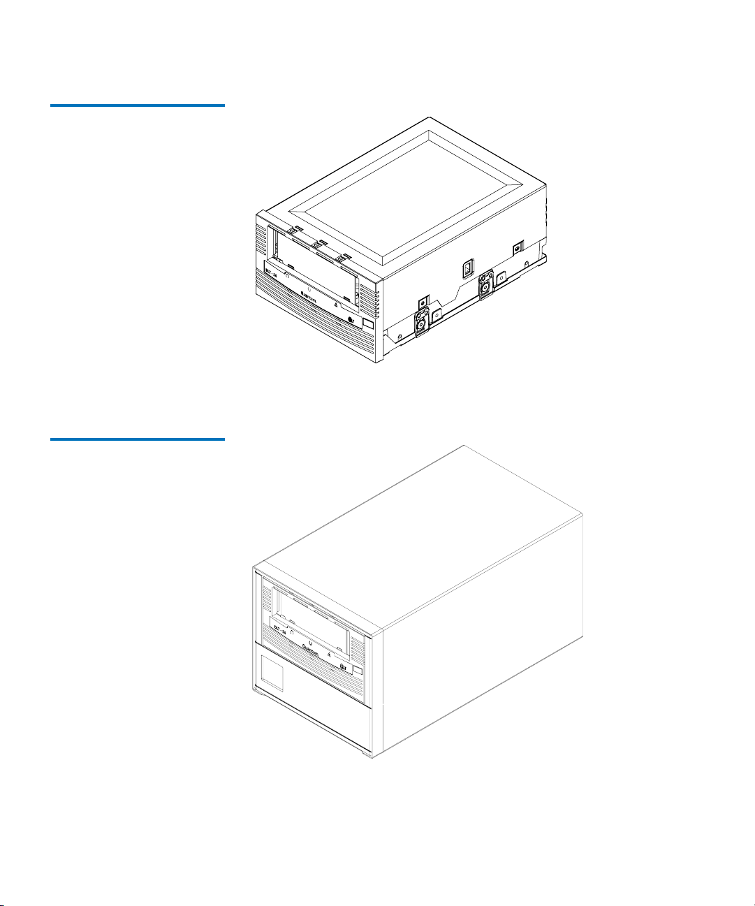
Figure 1 Internal Tape Drive
Chapter 1 Product Information
Overview
Figure 2 Tabletop Tape Drive
DLT-S4 Product Manual 3
Page 20

Chapter 1 Product Information
Tape Drive System
Tape Drive System 1
The DLT-S4 tape drive system provides the following product features:
Feature Description
Media A streaming tape drive that uses half-inch wide
DLTtape S4 media
Form Factor A standard 5.25-inch full-height form factor to
simplify integration into system and tape library
solutions
Backward
Read
Compatibility
Interface
Options
Capacity
a. Fibre Channel is not available with the tabletop model.
b. In accordance with industry practice, a typical compression
ratio is quoted. Actual compression ratios depend on the
redundancy and kind of data files you write.
Tape Drive Cartridge
DLT-S4 DLTtape S4
SDLT 600 Super DLTtape II
SDLT 320 Super DLTtape I
Ultra320 SCSI
4 Gb Fibre Channel
Mode Value
Native capacity 800 GB
Compressed capacity 1600 GB
a
b
(2:1 compression ratio)
DLT-S4 Product Manual 4
Page 21

Chapter 1 Product Information
Tape Drive Technology
Tape Drive Technology 1
The DLT-S4 tape drive incorporates state-of-the-art technologies that
contribute to the SDLT architecture. Some of these ideas are trademarked,
others are patented. The following subsections introduce the important
technologies that together, comprise the DLT-S4 tape drive system.
Table 1 Tape Drive System
Technology Description
Laser Guided
Magnetic Recording
Magneto Resistive
Cluster Heads
Advanced Partial
Response Maximum
Likelihood
Advanced Metal
Powder Media
Positive Engagement
Tape Leader
Buckling Mechanism
The DLT-S4 tape drive system (see figure 1
Laser Guided Magnetic Recording (LGMR) technology. LGMR provides a
unique combination of the best optical and magnetic technologies, which
results in dramatically higher capacities by substantially increasing the number
of recording tracks on the data-bearing surface of the media.
Magneto Resistive Cluster (MRC) heads are a densely packed array of small
Magneto Resistive (MR) tape heads precisely positioned using advanced thinfilm processing technology.
Improving on Partial Response Maximum Likelihood (PRML) technology
traditionally used in disk drives and communication systems, Quantum’s
advanced PRML channel technology, co-developed with Lucent Technologies,
brings new levels of performance and capacity to high-performance linear tape
products.
Advanced Metal Powder (AMP) media is a state-of-the-art media using
durable metal powder technology for recording high densities of data. The
back side of AMP media receives a specially formulated coating to accept the
optical servo tracks, which ensures that the entire data-bearing side of the
media is available for recording data and eliminates the need for preformatting.
The positive engagement tape leader buckling mechanism engages the media
leader on cartridge load and disengages it on cartridge unload. It uses a metal
pin attached to the tape drive leader to link with molded clips permanently
attached to the media leader inside the cartridge.
and figure 2) is based on Quantum’s
DLT-S4 Product Manual 5
Page 22

Chapter 1 Product Information
Tape Drive Design
Tape Drive Design 1
The DLT-S4 tape drive is designed as a total system. The system includes
a complex interaction of a number of important components including
such items as the tape path, tape heads, media, cartridge, and host
interface.
For a detailed description of the integrated drive components, see the
DLT-S4 Product Specification (81-81279-xx).
Table 2 Tape Drive Components
Components Description
Base mechanical
assembly
Front-panel assembly
(bezel)
The base mechanical assembly houses the tape control mechanical, actuator,
reel motor, load mechanism, eject button, and front-panel indicators. It
positions the actuator servo head over the correct tape track. It implements the
functions required to buckle and unbuckle the media and control the media
motion. It is the mechanism responsible for engaging the media leader on
cartridge load and disengaging it on cartridge unload.
Auto load—The tape auto load is a soft load and seating mechanism that is
tolerant of forced media loading; a media sensor is triggered upon cartridge
insertion, and after the media reaches a hard stop point, the auto load sensor
engages pulling the cartridges the remaining distance onto the motor. On
media ejection, the assembly reverses the process and automatically ejects the
cartridge a fixed distance from the front of the tape drive
Base plate—Acts as the support platform for the other modules and for the
tape drive enclosure. It also includes the mounting holes (shock mounts) used
to install the tape drive into a server or tape library.
The front-panel assembly (bezel) performs these functions:
• Protects the front of the drive from physical damage
• Channels airflow through the system
• Aligns the cartridge when it is inserted into the system
• Provides label identifiers for the LEDs mounted on the front of the tape
drive
DLT-S4 Product Manual 6
Page 23

Chapter 1 Product Information
Tape Drive Design
Components Description
• Enables cartridge ejection
• Reduces internal environmental contamination with a built-in dust door
(internal and tabletop configurations only)
Board assemblies The board assemblies provide the main control function for the system and the
interface from the system to the host computer, library, or autoloader. This
provides the Advanced Partial Response Maximum Likelihood (PRML) feature
of the Quantum SDLT technology.
There are three board assemblies:
• Pre-amplifier Board (PAB) — The PAB contains the preamplfier for the read
heads, and the write driver for the write heads.
• Motor Driver Board (MDB) — The MDB interfaces with the reel motor
drivers and hall sensors, actuator driver and sensors, sensor and motor
drives for the soft load, LEDs for front-panel indicators, and eject button
signals.
• Drive Control Board (DCB) — The DCB is the main control card for the DLTS4 tape drive. It sends commands to the MDB to control and drive the tape
mechanism. The board interfaces with the PAB to send signals to the head
for reading and writing.
DLTSage See DLTSage Application Software
DLTIce See DLTIce Firmware
Cartridges See DLTtape S4 Cartridge
DLT-S4 Product Manual 7
.
.
.
Page 24
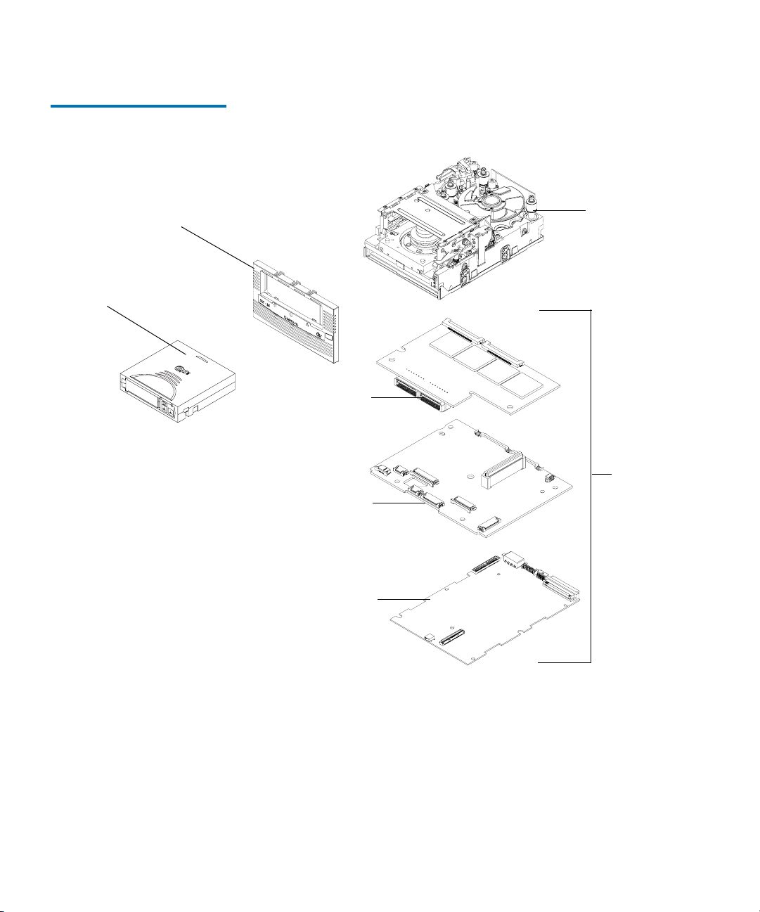
Figure 3 Tape Drive Integrated
Components
Chapter 1 Product Information
Tape Drive Design
Front panel
assembly (bezel)
Cartridge
Base
mechanical
assembly
PAB
Board
assemblies
MDB
DCB
DLT-S4 Product Manual 8
Page 25

Chapter 1 Product Information
Tape Drive Design
DLTSage Application Software
DLTSage is a suite of preventative maintenance diagnostic software tools
that enables users to more simply manage tape storage environments. It
1
enhances manageability by allowing you to manage, predict, and prevent
problems that can occur during a routine backup.
DLTSage software is a standard feature of the DLT-S4 tape drive and the
DLTtape S4 cartridge. To learn more about DLTSage, see:
•
www.dltsage.com
• DLTSage and DLTIce User’s Guide (81-81279-xx)
Table 3 DLTSage Features
Feature Description
Manage The software ensures that you use tape drives and media as efficiently as possible.
• It provides management protocols for acquiring information on DLT tape drives
and media anywhere on an enterprise network
• It helps you to understand and control how tape drives are used throughout the
system
• It allows you to develop a complete inventory of tape drives and media and the
usage statistics for each
Predict The software continuously monitors usage patterns and then interprets and
analyzes the operational information.
• You can ascertain which cartridges and which tape drives are nearing the end of
their useful lives
• You can predict when the tape drive needs cleaning
• You can use tape drive and cartridge usage statistics to implement predictive
maintenance parameters
Prevent The software allows you to see errors as they happen and correct them instantly.
• It alerts you to potential problems, enabling you to take corrective action
immediately
• It provides management protocol interfaces for third-party providers, such as
library and backup software vendors, to use key information across multiple
interfaces.
DLT-S4 Product Manual 9
Page 26

Chapter 1 Product Information
Tape Drive Design
DLTIce Firmware 1 Quantum’s DLTIce firmware is an extension of the DLTSage architecture.
It acts as the compliance management function of DLTSage. The
firmware allows you to append data to an “iced” cartridge, but you
cannot rewrite, reformat, or erase the data.
This feature uses a Write Once, Read Many (WORM) functionality, which
provides you with the securely archived records that are needed to
achieve government regulatory compliance.
Quantum’s DLTIce firmware is a standard feature of the DLT-S4 tape
drive.
To learn more about DLTIce, see:
•
www.dltsage.com
• DLTSage and DLTIce User’s Guide (81-81279-xx)
Table 4 DLTIce Features
Feature Description
Security The tape drive’s firmware places an electronic signature key on each cartridge to
ensure that data written to the media cannot be rewritten, reformatted, or erased.
• The key is a unique identifier that cannot be altered
• The firmware allows you to append new data to the cartridge
• The cartridge initialization process assures that only unformatted cartridges will
be WORM enabled
Verification The verification is a two part process.
• The DLT-S4 tape drive provides best-of-class verification through its ECC
algorithms
• The firmware provides archive media verification and tamper verification with
time and date signatures
DLT-S4 Product Manual 10
Page 27

Chapter 1 Product Information
Tape Drive Design
Feature Description
Identification The identification applies to both the data and the cartridges.
• The storage management software issues a time and date stamp, which enables
you to locate and authenticate specific records using ISV compliant storage
management software
• The cartridge used for DLTIce is a standard DLTtape S4 cartridge. Load the
firmware through DLTSage and use the special yellow labels provided by
Quantum to identify the WORM cartridges
Duplication The data stored on the DLTtape S4 cartridge can be downloaded to another storage
media through any ISV-compliant storage management software.
See “Icing” a Cartridge
on page 91 for instructions on how to create a WORM
cartridge.
DLTtape S4 Cartridge 1 A cartridge is a significant component of any tape drive system. The
DLT-S4 tape drive writes to DLTtape S4 cartridges.
• Color and Pattern — The DLTtape S4 cartridge is and has a
distinctive pattern, in addition to the DLTtape logo, molded in the
plastic.
• Geometry — The cartridge’s geometry is similar to previous DLTtape
cartridges to simplify integration with existing tape library designs,
but has a keying feature to ensure it cannot be loaded into previous
generations of tape drives where writing to the media is
incompatible.
• Debris Resistance — The cartridge is made of wear-resistant
materials to reduce the potential for debris generation and increase
the life of the cartridge.
For more information on cartridges, see appendix A
on page 75.
DLT-S4 Product Manual 11
Page 28

Chapter 1 Product Information
Interface Types
Interface Types 1
This section contains the following information for the DLT-S4 tape drive:
• Host Interface
• Ultra320 SCSI Interface
• Fibre Channel Interface
• Physical Interface
Host Interface 1 The DLT-S4 tape drive comes in these interface types:
• Tabletop model with Ultra320 SCSI interface
• Internal model with either an Ultra320 SCSI interface or a 4 Gb
Optical Fibre Channel interface
These versions provide two possible parallel SCSI interface types and one
Fibre Channel interface type that can be configured to run at a fast speed
or a low speed (see table 5
).
Table 5 Interface Versions,
Speeds, and Options
Interface
Versions
Speeds
(Maximum Burst) Protocol Options
Ultra320 320 MB/second
a
Low Voltage Differential (LVD)
sense running up to 320 MB per
second burst
Ultra160 2/FAST-20/
Asynchronous
Fibre
Channel
100 MB/second
b
200 MB/second
400 MB/second
Class3
Connect to N port, NL port,
FL port, and F port
a. The SCSI bus itself limits this speed, not the design of the tape
drive or media.
b. Fibre Channel interface is not available in the tabletop model.
DLT-S4 Product Manual 12
Page 29

Chapter 1 Product Information
Interface Types
Ultra320 SCSI Interface 1 The DLT-S4 tape drive conforms to the Ultra320 SCSI standard and
allows for a maximum burst rate of 320 MB per second.
SCSI Stub and Cable Lengths
The longest stub length on the DLT-S4 PCBA is 1.64 inches, and the
maximum cable length for one DLT-S4 tape drive is 20 meters. The
maximum SCSI cable interconnect length is 10 meters total with a
maximum of two DLT-S4 tape drives on the bus.
To operate properly in Ultra320 mode, ensure that all SCSI cables and
terminators are Ultra320 (SPI-4) compatible.
For more information on
• The SCSI interface, see the DLT-S4 SCSI Interface Guide (81-81281-xx)
• Speeds and protocol options, see table 5
Fibre Channel Interface 1 The Fibre Channel interface operates at speeds up to 4 Gb/second.
Fibre Channel can support up to 126 devices in a loop configuration.
Longwave transceivers (with fiber optic cable) support distances up to
10 kilometers; short pulsewave transceivers (with fiber optic cable)
support distances up to 500 meters.
For more information on:
• The Fibre Channel interface, see the DLT-S4 SCSI Reference Guide
(81-81281-xx)
1
• Speeds and protocol options, see table 5
Also, see the latest Fibre Channel reference documentation available at
http://www.t10.org.
Physical Interface 1 This section lists the physical interfaces for the tape drive. These
interfaces are available from the rear panel (per type, per port).
DLT-S4 Product Manual 13
Page 30

Chapter 1 Product Information
Interface Types
Table 6 Tape Drive Interfaces
Interface
Versions Physical Characteristics
Fibre
Channel
Topology-constrained (drive automatically detects
topology)
4 Gbit interface (drive automatically detects speed)
LC connector with 850 nanometer SFP transceiver
(supplied)
Parallel SCSI Ultra320
LVD
SCSI ID/TERMPWR connector style: 6-pin
Connector style: 68-pin high density SCSI
DLT-S4 Product Manual 14
Page 31

Chapter 1 Product Information
Quantum Diagnostics Tools
Quantum Diagnostics Tools 1
Quantum frequently provides new and updated tools to use with its tape
drives. These tools include such items as upgrades for product software
and firmware, and diagnostic software that may be newly developed.
The tools are available on Quantum’s Web site.
Note: These tools are only available to registered Quantum
customers.
Follow these steps to access these tools:
1 Go to the Quantum Web site: www.quantum.com.
2 Click service and support in the upper menu bar. This opens the
Service and Support window.
3 Explore the various pages that comprise Service and Support until
you find what you need.
New tools and utilities get added frequently, so check back often.
DLT-S4 Product Manual 15
Page 32

Chapter 1 Product Information
TapeAlert
TapeAlert 1
DLT-S4 tape drives are delivered with TapeAlert features built in. The
tape drive firmware constantly monitors the device’s hardware and
media, checking for errors and potential difficulties. It flags any problems
identified on the
After a backup, the TapeAlert-compatible backup application
automatically reads the device’s TapeAlert
check for any problems. If an error is flagged, your backup software
displays a warning message on your screen, and adds the TapeAlert
messages to its logs. These messages are standard across all applications
that support TapeAlert, and give an explanation of the problem and
suggested resolution. For example, if you were attempting to back up to
an expired cartridge, you would see the following message:
WARNING: The data cartridge has reached the end of its calculated useful life.
Copy any data you need to another cartridge.
Discard the old cartridge.
SCSI LOG SENSE Page 2Eh.
SCSI LOG SENSE Page 2Eh to
Medium Auxiliary Memory 1
Medium Auxiliary Memory (MAM) is a feature in the DLT-S4 tape drive
that produces various attributes about the cartridge and records them on
the media itself. These attributes provide the underlying information for
Quantum’s DLTSage suite of predictive and preventive maintenance
diagnostics software.
For more information on MAM, see:
• DLT-S4 SCSI Reference Guide (81-81281-xx)
For more information on DLTSage, see:
•
www.dltsage.com
• DLTSage and DLTIce User’s Guide (81-81297-xx)
DLT-S4 Product Manual 16
Page 33

Chapter 2
2Tape Drive Installation
This chapter describes how to configure and install the DLT-S4 tape drive.
This includes configuration jumper settings, connector pin assignments,
and power and signal cabling descriptions.
• Warranty Note
follow so you do not void your warranty
• Safety, Handling, and ESD Protection
safeguards to use while working with the DLT-S4 tape drive system
• Pre-Installation Guidelines
installing the tape drive in a system
• Internal SCSI Tape Drive Configuration
an internal tape drive with the SCSI interface into a system
• Internal SCSI Tape Drive Installation
internal tape drive with the SCSI interface into a system
• SCSI Connectors and Pin Assignments
about the SCSI connectors
• Internal Fibre Channel Tape Drive Installation
configure and install an internal tape drive with the Fibre Channel
interface into a system
• Tabletop Tape Drive Installation
version of the tape drive
• Installation Confirmation Procedure
the tape drive has been installed correctly
provides a general reminder of certain precautions to
describes appropriate
describes proper steps to take before
describes how to configure
describes how to install an
lists relevant information
describes how to
describes how to install the tabletop
describes how to confirm that
DLT-S4 Product Manual 17
Page 34

Chapter 2 Tape Drive Installation
Warranty Note
W arranty Note 2
See the tape drive warranty before installing the tape drive; the tape
drive’s warranty could be voided if the installation guidelines and
restrictions are not closely followed.
Generally, the Limited Product and Limited Repair Warranties are
contingent upon proper use in the application for which the product is
intended; and do not cover the product if you perform any of the
following actions:
• Modify the product without the manufacturer’s written approval
• Subject the product to unusual physical, environmental, or electrical
stress, including damage caused by handling or shipping in
unapproved containers or packaging
• Disturb any warranty labels, or the integrity of the product in any
other way
• Remove or damage the serial number label to the extent that
warranty status of the product cannot be determined
Safety, Handling, and ESD Protection 2
Inappropriate or careless handling of DLT-S4 tape drive systems may
result in damage to the product. Follow the precautions and directions to
prevent damaging the DLT-S4 tape drive system. In addition, follow the
steps in Pre-Installation Guidelines
the correct hardware for the system configuration.
DLT-S4 Product Manual 18
on page 22 to ensure that you have
Page 35

Chapter 2 Tape Drive Installation
Safety, Handling, and ESD Protection
Safety Precautions 2 For your safety, follow all safety procedures described here and in other
sections of the document.
1 Power off the system before installing or removing the tape drive to
prevent the possibility of electrical shock or damage to the tape drive.
2 Unplug the unit that contains—or is to contain—the tape drive from
AC power to provide an added measure of safety.
3 Read, understand, and observe all label warnings.
The POS uses a Class I laser product. This laser product complies
with 29 CFR 1200 and 29 CFR 1910 as applicable on the date of
manufacture.
Warning: If you open the tape drive chassis, you may become
exposed to invisible laser emission which could be
harmful if you are directly exposed to the beam.
Handling Instructions 2 Damage to the DLT-S4 tape drive system can occur as the result of
careless handling, vibration, shock, or electrostatic discharge (ESD). For
more details on ESD, see Electrostatic Discharge Protection
on page 20.
Caution: Never power off the tape drive or the host while the tape
drive contains a cartridge. Failure to remove a cartridge
may result in cartridge or tape drive damage.
Follow these guidelines to avoid damage to the tape drive.
Do or
Do Not Handling and Using Guidelines
Do • Always handle the tape drive carefully and gently— a
drop of ¼ inch onto a bench or desktop can damage a
tape drive
• Always place the tape drive on a flat, stable surface
• Hold the internal tape drive only by its sides
Caution: Never hold the tape drive by inserting your
fingers into the receiver area on the front of the
tape drive. You could damage the receiver area
if you lift or carry it in this manner.
DLT-S4 Product Manual 19
Page 36

Chapter 2 Tape Drive Installation
Safety, Handling, and ESD Protection
Do or
Do Not Handling and Using Guidelines
Do Not • Bump, jar, or drop the tape drive—use care transporting
the tape drive.
• Place the tape drive so that it rests on its front bezel
Always gently place the tape drive flat, printed circuit
board (PCB) side down, on an appropriate ESDprotected work surface to avoid the tape drive being
accidentally knocked over.
• Stack objects on the tape drive
• Expose the tape drive to dusty, humid, or smoke-filled
areas
• Place foreign objects inside the tape drive’s receiver area
Do or
Do Not Storage Guidelines
Do Not • Stack objects on the tape drive
• Expose the tape drive to dusty, humid, or smoke-filled
areas
Electrostatic Discharge Protection
Several electrical components of the DLT-S4 tape drive system are
sensitive to static electricity and electrostatic discharge (ESD). Even a
2
static buildup or discharge that is too slight to feel can be sufficient to
destroy or degrade a component’s operation.
To minimize the possibility of ESD-related damage to the system, the
tape drive’s manufacturer strongly recommends using both a
workstation antistatic mat and an ESD wrist strap. If the devices are
correctly installed and properly used, they reduce the buildup of static
electricity that might harm the system.
DLT-S4 Product Manual 20
Page 37

Chapter 2 Tape Drive Installation
Safety, Handling, and ESD Protection
Follow these guidelines to avoid damage to the tape drive.
Do or
Do Not ESD Guidelines
Do Always use proper electrostatic discharge (ESD) protection.
• Use a properly fitted wrist strap or other suitable ESD
protection
• Observe proper ESD grounding techniques
• Keep the internal tape drive in its antistatic bag until
ready to install
• Place the tape drive in the antistatic bag before placing it
in a shipping container
• Hold the tape drive only by its sides
• Place the tape drive on a properly grounded antistatic
work surface pad while it is out of its protective
antistatic bag
Do Not • Pack other materials with the tape drive in its antistatic
bag
• Use the bag as a substitute for the work surface antistatic
pad
The outside surface of the bag may not have the same
antistatic properties as the inside surface. It could
actually increase the possibility of ESD problems.
• Remove covers to use any test equipment to check
components on the PCBAs
There are no user-serviceable components on the tape
drive.
DLT-S4 Product Manual 21
Page 38

Chapter 2 Tape Drive Installation
Pre-Installation Guidelines
Pre-Installation Guidelines 2
Before you install the tape drive in a system, follow these steps. Also,
check the tape drive to be certain it is operating properly before installing
it in a system.
1 Unpack and review the contents of the box for any physical damage.
If you find damaged items, contact the tape drive provider.
2 Record the model and serial number of the DLT-S4 tape drive system.
These numbers provide specific information on the DLT-S4 tape
drive system and will be helpful if you must contact technical
support. You can find these numbers on the bottom of the tape drive
enclosure.
Model Number
(usually begins with TR)
3 Check the enclosed SCSI (or Fibre Channel) cable to ensure it is
Serial Number
(usually begins with RB)
compatible with the SCSI (or Fibre Channel) controller card in the
host computer.
4 Check the SCSI (or Fibre Channel) interface on the host computer to
ensure that it is compatible with the tape drive.
See table 6
on page 14 for a list of the possible interfaces that are
available and the various options with each.
5 Confirm that your back-up software and operating system are
compatible with the tape drive.
See
www.dlttape.com for the most up-to-date compatibility
information.
DLT-S4 Product Manual 22
Page 39

Chapter 2 Tape Drive Installation
Internal SCSI Tape Drive Configuration
Internal SCSI Tape Drive Configuration 2
This section provides information for configuring a tape drive with SCSI
interface into a system. See Tabletop Tape Drive Installation
for information on configuring and installing a tabletop tape drive.
Caution: Before you begin, review the safety, ESD, and handling
precautions described at the beginning of this chapter to
avoid personal injury or damage to equipment.
Configure the DLT-S4 tape drive system with a SCSI interface by
following the steps detailed in the following subsections.
If you want to change any of the settings, refer to the applicable
subsection; otherwise proceed directly to the tape drive’s installation
procedures in Internal SCSI Tape Drive Installation
on page 28.
on page 45
Setting the Internal Tape Drive SCSI ID
This section tells you how to set the SCSI ID on the internal tape drive via
the jumper block. Each device on the SCSI bus must have a unique SCSI
2
ID address assigned to it.
Note: For specific recommendations for assigning SCSI IDs, refer to
the system or SCSI controller documentation.
Set the SCSI ID by placing the supplied jumpers on a set of pins at the
rear of the tape drive (see figure 4
See figure 4
SCSI ID. See table 7
tape drive.
for the empty 12-pin jumper block that you use to set the
for the location of the jumper block on the rear of the
, table 7, and table 8).
DLT-S4 Product Manual 23
Page 40

Figure 4 Detail of the Empty
SCSI ID Connector
Chapter 2 Tape Drive Installation
Internal SCSI Tape Drive Configuration
You can configure internal tape drives for SCSI ID addresses that range
from 0 to 15 in one of two ways:
• Place a jumper on the 12-pin SCSI ID block located on the rear of the
tape drive (see table 7
)
• Set the SCSI ID through firmware in a library setting
Table 7 SCSI ID Address
Selections
Note:
The firmware default is SCSI ID 5 and assumes no jumpers
are installed on the jumper block. If you omit all jumpers
from the SCSI ID connector, the tape drive will use the
default setting of 5.
The default setting for the tape drive is 5; the host adapter setting is
typically SCSI ID 7. If you choose to omit all jumpers from the SCSI ID
block, the tape drive will use the default setting of 5.
SCSI ID
01
2
3
Jumper
Block
SCSI ID
4
5 (default) 6
7
Jumper
Block
SCSI ID
89
10 11
Jumper
Block
SCSI ID
12 13 14
15
Jumper
Block
DLT-S4 Product Manual 24
Page 41

Chapter 2 Tape Drive Installation
Internal SCSI Tape Drive Configuration
Figure 5 Rear Panel SCSI
Connectors
SCSI port
(68 pin)
Note:
The computer system and the tape drive SCSI IDs are only
checked when you power cycle both. To change the SCSI ID
after installation, turn off both the system and the tape drive,
change the tape drive’s SCSI ID, turn on the tape drive, and then
turn on the system.
SCSI ID (includes
TERMPWR Enable)
Library connector
(10 pin)
or denotes pin #1
DLT-S4 Product Manual 25
Page 42

Chapter 2 Tape Drive Installation
Internal SCSI Tape Drive Configuration
Table 8 SCSI ID Address
Selections (Tabular Format)
SCSI ID Jumper Across Pins
a
9-10
7-8 5-6 3-4 1-2
010000
110001
210010
310011
410100
5
00000
(default)
610110
710111
811000
911001
1011010
1111011
1211100
1311101
1411110
1511111
Note: 0 = No Jumper Installed, 1 = Jumper Installed
a. Jumpering pins 9-10 forces the tape drive to ignore the firmware value and read
the value jumpered on the block.
Termination 2 You must terminate a SCSI bus at each end of the bus. Terminate all
signals not defined as RESERVED, GROUND, or TERMPWR exactly once
at each end of the bus. At least one device must supply terminator power
(TERMPWR).
DLT-S4 Product Manual 26
Page 43

Figure 6 Enabling TERMPWR
Chapter 2 Tape Drive Installation
Internal SCSI Tape Drive Configuration
• To enable TERMPWR — Install the jumper across pins 11 and 12 on
the SCSI jumper block (see figure 6
)
• To disable TERMPWR — Remove the jumper
TERMPWR
Enable
denotes pin #11
denotes pin #12
DLT-S4 Product Manual 27
Page 44

Chapter 2 Tape Drive Installation
Internal SCSI Tape Drive Installation
Internal SCSI Tape Drive Installation 2
Installing the Internal Tape Drive
Figure 7 Internal T ape Drive —
Front View
Figure 8 Internal T ape Drive —
Rear View
This section tells you how to install an internal SCSI tape drive (see
figure 7
2
and figure 8).
DLT-S4 Product Manual 28
Page 45

Chapter 2 Tape Drive Installation
Internal SCSI Tape Drive Installation
Securing the Internal T ape Drive
This section describes how to mount and secure the tape drive in the
system. Because of the variety of mounting possibilities for tape drives,
2
the instructions presented here are general guidelines. Use these
instructions only as a guide for mounting the tape drive in the system.
Note: In some system configurations, it may be more convenient to
connect the SCSI bus and power cables to the tape drive before
securing it in the system.
Mount the tape drive in the system by performing the following steps:
1 Position the tape drive in the system and align the tape drive
mounting holes (side or bottom) with those in the system (see
figure 9
, figure 10, and figure 11).
Caution: The screws used to mount the tape drive must be
M3 x 8mm long. This kind of screw is exactly the
proper length and will not damage the tape drive.
2 Secure the tape drive in the bay or chassis using four M3 x 8mm long
screws.
DLT-S4 Product Manual 29
Page 46

Figure 9 Dimensions — Tape
Drive Front View
Chapter 2 Tape Drive Installation
Internal SCSI Tape Drive Installation
Figure 10 Dimensions — Tape
Drive Right Side View
DLT-S4 Product Manual 30
Page 47

Figure 11 Dimensions — Tape
Drive Bottom View
Chapter 2 Tape Drive Installation
Internal SCSI Tape Drive Installation
DLT-S4 Product Manual 31
Page 48

Chapter 2 Tape Drive Installation
Internal SCSI Tape Drive Installation
Connecting the Internal Tape Drive Cables
Connecting the SCSI and Power Cables
This section discusses connectors on the rear of the internal tape drive:
2
•SCSI
•Power
• Optional library/loader connectors
Follow these steps to connect the SCSI and power cables.
2
1 Ensure that both the tape drive and computer are turned off—before
connecting the tape drive to the host computer.
2 Ensure that the SCSI cables and terminators are SPI-3 (or SPI-4)
compatible.
SPI refers to SCSI Parallel Interface; you can learn more from this
standard at the Web site
3 Connect only the tape drive to the host computer at this time—if you
www.t10.org.
are connecting several devices to the SCSI bus.
Confirm that the host computer and tape drive are communicating
correctly before adding additional devices.
4 The SCSI bus must be terminated at each end. You may need to
terminate this tape drive if one of the following conditions exist:
• The DLT-S4 tape drive is the only device connected to the SCSI
bus
• The DLT-S4 tape drive is one of several devices connected to the
SCSI bus, and it is the last device connected to the SCSI bus
If either of these conditions exist, attach a “Y” adapter cable to the
tape drive’s SCSI connector; then attach the SCSI cable to one leg of
the “Y” and attach the terminator to the other leg. Carefully connect
the cables, to avoid bending or damaging the connector pins.
Note: You must supply the “Y” adapter cable.
5 Attach the power cable to the tape drive.
6 Check all cable and termination connections and ensure that they are
attached correctly and seated firmly before you turn on the system.
DLT-S4 Product Manual 32
Page 49

Chapter 2 Tape Drive Installation
Internal SCSI Tape Drive Installation
See figure 12 for the pin orientation of the 68-pin SCSI connector and the
4-pin power connector located on the rear of the internal tape drive. See
SCSI Connectors and Pin Assignments
on page 34 for these connectors
and pin assignments:
• Low Voltage Differential (LVD) mode
• Power cable pin assignments
Using the Optional Loader Connector
Figure 12 Rear Panel
Connectors
SCSI port
(68 pin)
The 10-pin optional loader connector provides signals to use in a loader/
library configuration. See figure 12
2
table 12
on page 38 for the loader connector pin assignments.
SCSI ID
(includes
terminator)
Loader/Library
connector (10 pin)
for the location of this connector; see
or denotes pin #1
Power
connector
(4 pin)
DLT-S4 Product Manual 33
Page 50

Chapter 2 Tape Drive Installation
SCSI Connectors and Pin Assignments
SCSI Connectors and Pin Assignments 2
This section shows the connector pin assignments for:
Table 9 MSE Mode SCSI
Connector Pin Assignments
• MSE Mode of SCSI (see table 9
• MSE LVD Mode of SCSI (see table 10
• The 4-pin connector (see table 11
• The 10-pin loader connector (see table 12
Signal Name Pin Number Pin Number Signal Name
Ground 1 35 -DB(12)
Ground 2 36 -DB(13)
Ground 3 37 -DB(14)
Ground 4 38 -DB(15)
Ground 5 39 -DB(P1)
Ground 6 40 -DB(0)
Ground 7 41 -DB(1)
Ground 8 42 -DB(2)
Ground 9 43 -DB(3)
)
)
)
)
Ground 10 44 -DB(4)
Ground 11 45 -DB(5)
Ground 12 46 -DB(6)
Ground 13 47 -DB(7)
Ground 14 48 -DB(P0)
Ground 15 49 Ground
Note: The minus sign (-) next to a signal indicates active low.
DLT-S4 Product Manual 34
Page 51

Chapter 2 Tape Drive Installation
SCSI Connectors and Pin Assignments
Signal Name Pin Number Pin Number Signal Name
DIFFSENS 16 50 Ground
TERMPWR 17 51 TERMPWR
TERMPWR 18 52 TERMPWR
Reserved 19 53 Reserved
Ground 20 54 Ground
Ground 21 55 -ATN
Ground 22 56 Ground
Ground 23 57 -BSY
Ground 24 58 -ACK
Ground 25 59 -RST
Ground 26 60 -MSG
Ground 27 61 -SEL
Ground 28 62 -C/D
Ground 29 63 -REQ
Ground 30 64 -I/O
Ground 31 65 -DB(8)
Ground 32 66 -DB(9)
Ground 33 67 -DB(10)
Ground 34 68 -DB(11)
Note: The minus sign (-) next to a signal indicates active low.
DLT-S4 Product Manual 35
Page 52

Table 10 MSE LVD Mode
SCSI Connector Pin
Assignments
Chapter 2 Tape Drive Installation
SCSI Connectors and Pin Assignments
Signal Name Pin Number Pin Number Signal Name
+DB(12) 1 35 -DB(12)
+DB(13) 2 36 -DB(13)
+DB(14) 3 37 -DB(14)
+DB(15) 4 38 -DB(15)
+DB(P1) 5 39 -DB(P1)
+DB(0) 6 40 -DB(0)
+DB(1) 7 41 -DB(1)
+DB(2) 8 42 -DB(2)
+DB(3) 9 43 -DB(3)
+DB(4) 10 44 -DB(4)
+DB(5) 11 45 -DB(5)
+DB(6) 12 46 -DB(6)
+DB(7) 13 47 -DB(7)
+DB(P) 14 48 -DB(P)
Ground 15 49 Ground
DIFFSENS 16 50 Ground
TERMPWR 17 51 TERMPWR
TERMPWR 18 52 TERMPWR
Reserved 19 53 Reserved
Ground 20 54 Ground
+ATN 21 55 -ATN
Note: The minus sign (-) next to a signal indicates active low.
DLT-S4 Product Manual 36
Page 53

Chapter 2 Tape Drive Installation
SCSI Connectors and Pin Assignments
Signal Name Pin Number Pin Number Signal Name
Ground 22 56 Ground
+BSY 23 57 -BSY
+ACK 24 58 -ACK
+RST 25 59 -RST
+MSG 26 60 -MSG
+SEL 27 61 -SEL
+C/D 28 62 -C/D
+REQ 29 63 -REQ
+I/O 30 64 -I/O
+DB(8) 31 65 -DB(8)
+DB(9) 32 66 -DB(9)
+DB(10) 33 67 -DB(10)
+DB(11) 34 68 -DB(11)
Note: The minus sign (-) next to a signal indicates active low.
T able 11 Power Connector Pin
Assignments
Pin Number Signal Name
1 +12 VDC
2 Ground (+12V return)
3 Ground (+5V return)
4 +5 VDC
DLT-S4 Product Manual 37
Page 54

Table 12 ADI/Loader Port
Interface Pin Assignments
Pin Number Signal Name T10 ADI Signal Name
Chapter 2 Tape Drive Installation
SCSI Connectors and Pin Assignments
1 FROM_LDR_H +Tx
2 FROM_LDR_L —Txa—Rx
—Rx
a
d
d
3Ground GND
4TO_LDR_L +Tx
5TO_LDR_H —Tx
6 Sense(d) / Ground Sense
7LOADER_PRESENT_L Sense
—Rx
d
d
d
a
—Rx
a
a
8 No Connect Reseta (Optional / Not Used)
9 No Connect Signal
10 No Connect Sense
(Optional / Not Used)
aux
(Optional / Not Used)
aux
DLT-S4 Product Manual 38
Page 55

Chapter 2 Tape Drive Installation
Internal Fibre Channel Tape Drive Installation
Internal Fibre Channel Tape Drive Installation 2
This section provides information for configuring and installing a tape
drive with the Fibre Channel interface into a system. See figure 13
DLT-S4 Fibre Channel connectors and jumper blocks located on the rear
of the tape drive.
The Fibre Channel interface is ONLY available with the internal model; it
is not available with the tabletop model.
Caution: Before you begin, review the safety, ESD, and handling
precautions described in Safety, Handling, and ESD
Protection on page 18 to avoid personal injury or damage
to equipment.
Figure 13 Fibre Channel
Connectors and Jumpers
for the
Fibre Channel
connector
Fibre Channel
Jumper Block
(includes terminator)
Loader connector
(10-pin)
or denotes pin #1
Power
connector
(4-pin)
To install and configure the tape drive, follow the steps in these
subsections.
DLT-S4 Product Manual 39
Page 56

Chapter 2 Tape Drive Installation
Internal Fibre Channel Tape Drive Installation
Table 13 Securing the Tape
Drive
This section describes how to mount and secure the tape drive in the
system.
Note: In some system configurations it may be more convenient to
connect the Fibre Channel and power cables to the tape drive
before securing it in the system.
Because of the variety of mounting possibilities for tape drives, the
instructions presented here are general guidelines. Use them only as a
guide for mounting the tape drive in the system.
Mount the tape drive in the system by performing the following steps:
1 Ensure that the host computer and all peripheral devices are turned
off.
2 Position the tape drive in the system and align the mounting holes
(side or bottom) with those in the system (see figure 9
figure 11
Caution: The screws used to mount the tape drive must be
on page 31).
, figure 10, and
M3 x 8mm long. This kind of screw is exactly the
proper length and will not damage the tape drive.
3 Secure the tape drive in the bay or chassis using four M3 x 8mm long
screws.
Connecting the Power 2 Follow these steps to connect power to the tape drive (see figure 13 for
the location of this connector; see table 11
for pin assignments for the
power connector).
1 Ensure that the tape drive and computer are turned off before
connecting the DLT-S4 tape drive to the host computer.
2 Connect only the tape drive to the host computer at this time—if you
are connecting several devices to the system.
Confirm that the host computer and tape drive are communicating
correctly before adding additional devices.
3 Attach the power cable to the tape drive.
4 Check all cable and termination connections and ensure that they are
attached correctly and seated firmly before you turn on the system.
DLT-S4 Product Manual 40
Page 57

Chapter 2 Tape Drive Installation
Internal Fibre Channel Tape Drive Installation
Using the Loader Connector
Connecting the Fibre Channel Cable
The 10-pin optional loader connector provides the signals you use when
the tape drive is part of a loader/library configuration (see figure 13
2
the location of this connector; see table 12
for the pin assignments).
This section describes how to connect the Fibre Channel cable.
2
Fibre Channel cables are “hot-swappable”, meaning you may connect
for
and disconnect them with unit power on. Therefore, unlike other
systems, the tape drive and computer may remain turned on to connect a
Fibre Channel tape drive to the host computer.
1 Insert the fiber optic cable into the Fibre Channel port on the rear of
the tape drive (see figure 14
).
The connector is fully seated when it snaps into the port.
2 Insert the other end of the fibre optic cable into the connector on the
host computer.
Verifying the Connection 2 The “link light” LED illuminates at the beginning of Fibre Channel POST
and extinguishes at the completion of Fibre Channel POST (this verifies
that the LED works). The LED also illuminates when Fibre Channel link
initialization is achieved, indicating the Fibre Channel link is working as
expected. The LED does not illuminate when there is no Fibre Channel
link established.
DLT-S4 Product Manual 41
Page 58

Figure 14 Connecting the Fibre
Channel Cable
Chapter 2 Tape Drive Installation
Internal Fibre Channel Tape Drive Installation
Fibre Channel port
Detail of the empty
Fibre Channel port
Fibre Channel link light
DLT-S4 Product Manual 42
Page 59

Chapter 2 Tape Drive Installation
Tabletop Tape Drive Configuration
Tabletop Tape Drive Configuration 2
This section provides instructions for configuring the tabletop model of
the DLT-S4 tape drive.
Note: The tabletop model comes ONLY with the SCSI interface. The
Fibre Channel interface is not available.
Configuring the Tape Drive
Figure 15 Tabletop Tape Drive
— Rear View
This model of tape drive is normally configured to meet customer
specifications before leaving the factory, so should not require any
2
internal configuration changes on site (see figure 15
for the location of the
controls and connectors for the tabletop tape drive).
SCSI
connectors
Power
connector
Power
switch
SCSI ID
Selector
Fan
Setting the SCSI ID 2 Each device connected to a SCSI bus must have a unique SDSI ID
number. The default SCSI ID for the tabletop tape drive is 3; you can
configure the tape drive for SCSI ID addresses that range from 0 to 15
using the SCSI ID pushbutton.
DLT-S4 Product Manual 43
Page 60

Figure 16 Tabletop SCSI ID
Selector Switch
Chapter 2 Tape Drive Installation
Tabletop Tape Drive Configuration
Note: Ensure that the tape drive’s SCSI ID is unique on the SCSI bus.
If the tape drive is the only SCSI device, leave the SCSI ID set
to 3, the default setting.
Do not use a SCSI ID of 7. This setting is typically reserved for
the SCSI controller.
Press the button above or below the ID number display to set the desired
SCSI ID (see figure 16
for a close-up view of the SCSI ID switch and its
location on the rear of the tabletop tape drive).
• To increase the ID number — Press the button above the number
• To decrease the ID number — Press the button below the number
SCSI ID
selector
Verifying Te rmination 2 The factory preconfigures the termination (TERMPWR) setting for the
tabletop tape drive according to specific customer requirements. You
cannot select TERMPWR on site.
DLT-S4 Product Manual 44
Page 61

Chapter 2 Tape Drive Installation
Tabletop Tape Drive Installation
Tabletop Tape Drive Installation 2
Tabletop tape drive installation consists of connecting SCSI bus and
power cables (see figure 15
Attaching the SCSI Cables 2 You can connect the SCSI bus cable leading from the host adapter to
either of the tape drive SCSI connectors.
• If the tape drive is the last device on the bus, install a SCSI terminator
on the open connector.
• If the bus continues from the tape drive to another SCSI device, install
a SCSI bus cable between the open connector and the next device on
the bus.
).
Figure 17 SCSI Chain —
Single Device
See figure 17
and figure 18 for the two connection methods.
SCSI
terminator
SCSI cable
connection
Follow these steps to install the tape drive as a single tape drive
connection.
1 Ensure that the tape drive and computer are turned off, prior to
connecting the tape drive to the host computer.
Caution: Never connect the tape drive while the host system or
peripheral devices are turned on.
DLT-S4 Product Manual 45
Page 62

Chapter 2 Tape Drive Installation
Tabletop Tape Drive Installation
Connect only the tape drive to the host computer at this time, if you
2
are connecting several devices to the SCSI bus.
Confirm that the host computer and tape drive are communicating
correctly before adding additional devices.
3 Terminate the SCSI bus at each end. Attach an active terminator onto
one end or the tape drive.
• If the tape drive is the only device connected to the SCSI bus,
attach the SCSI terminator to one of the connectors on the rear of
the tape drive (see figure 17
).
• If the tape drive is one of several devices connected to the SCSI
bus, and it is the last device connected to the SCSI bus, attach the
SCSI terminator to one of the connectors on the rear of the tape
drive (see figure 18
4 Carefully connect the SCSI cable, to avoid bending or damaging the
).
connector pins.
5 Connect the other end of the SCSI cable to the SCSI connector on the
host computer.
6 Snap the wire cable clamps into place to secure the cables.
7 Check all the cable and termination connections and ensure that they
are attached correctly and seated firmly.
DLT-S4 Product Manual 46
Page 63

Figure 18 SCSI Chain —
Multiple Devices
Chapter 2 Tape Drive Installation
Tabletop Tape Drive Installation
SCSI
terminator
SCSI cable
connector
SCSI cable
connector
Follow these steps to install the tape drive as a daisy-chain connection.
1 Ensure that all devices have unique SCSI IDs (see Setting the SCSI ID
on page 43).
2 Ensure that the tape drive and computer are turned off, prior to
connecting the tape drive to the host computer.
Caution: Never connect the tape drive while the host system or
peripheral devices are turned on.
3 Connect the SCSI cable from the host computer to the lower SCSI
connector on the rear of the tape drive.
4 Continue the SCSI chain using the upper SCSI connector.
5 Terminate the tape drive by attaching a terminator to the upper SCSI
connector.
Note: You must terminate the SCSI bus. The SCSI controller
terminates one end, while a terminator on the last device
in the chain terminates the other end.
DLT-S4 Product Manual 47
Page 64

Chapter 2 Tape Drive Installation
Tabletop Tape Drive Installation
Connecting the AC Power Cable
An AC power cable is supplied with each tabletop unit. Carefully inspect
the power cable and ensure that the cable is the appropriate cable for
2
your country or region based on the following criteria.
Warning:
Do not attempt to modify or use a tabletop 100–115 V AC
power cable for 220–240 V AC input power. Modifying the
power cable in any way can cause personal injury and
severe equipment damage.
The AC power cable used with the tabletop unit must meet the following
criteria:
• The power cable should be a minimum of 18/3 AWG, 60 °C, type SJT
or SVT
• UL and CSA certified cordage rated for use at 250V AC with a current
rating that is at least 125% of the current rating of the product
• You must terminate the AC plug in a grounding-type male plug
designed for use in your country or region. It must also have marks
showing certification by an agency acceptable in your country or
region
• The tabletop unit cable connector must be an IEC type CEE-22 female
connector
• The cable must be no longer than 4.5 meters (14.5 feet)
• The cable must be FCC compliant with emissions specifications
See figure 19
for the AC power cable plug-end types for 115 V AC and
220/240 V AC usage.
Figure 19 AC Power Cable
Connector Types
DLT-S4 Product Manual 48
Page 65

Chapter 2 Tape Drive Installation
Installation Confirmation Procedure
The tabletop unit power supply has an auto-sensing feature; it requires
no adjustment or switch setting changes for different AC sources.
1 Connect one end of the AC power cable into the power connector on
the rear of the tabletop tape drive (see figure 10
15 on page 43).
2 Connect the other end of the power cable to the AC outlet.
On completion, proceed to the next section to confirm the installation.
on page 30 and figure
Installation Confirmation Procedure 2
To confirm the installation:
1 Turn on the DLT-S4 tape drive system.
2 Turn on the host computer.
The screens displayed at power-on contain:
•BIOS
•Operating system
• SCSI controller information
If the first screen displays host adapter and SCSI ID information, that
means the installation was successful.
See Tape Drive Troubleshooting
successful.
DLT-S4 Product Manual 49
on page 64 if the installation is not
Page 66

Chapter 3
3Tape Drive Use
This chapter describes how to start using the DLT-S4 tape drive system.
This includes making a trial back-up, cleaning the tape mechanism, and
various troubleshooting information. This chapter also includes
information on the LEDs and buttons on the front panel of the system.
This chapter covers the following topics:
• Power-On Self-Test
when power is first applied to the tape drive
• Performing a Trial Back-up
ensure proper operation of the system
• Firmware Update via the SCSI Bus
firmware that resides inside the tape drive and controls its behavior
• Cleaning the Tape Mechanism
mind while using cleaning cartridges
• Front Panel Controls and LEDs
front panel controls and LEDs
• Tape Drive Troubleshooting
tools to use if the tape drive system fails
• Optimizing the Tape Drive Performance
optimize the performance of the tape drive
DLT-S4 Product Manual 50
describes the sequence of activities that occur
describes how to back up a sample file to
describes how to update the
describes the considerations to keep in
describes the functionality of the
lists troubleshooting tips and diagnostic
lists the steps to take to
Page 67

Chapter 3 Tape Drive Use
Power-On Self-Test
Power-On Self-Test 3
The DLT-S4 tape drive system performs a self-diagnostic test, called a
Power-On Self-Test (POST) each time you turn on the tape drive (see
table 14
POST completes in approximately 10 seconds. While POST is running,
the tape drive system responds BUSY to SCSI commands, but will
respond to various SCSI messages.
During this time, if a host tries to negotiate:
• Synchronous transfer — the tape drive system negotiates to
• Wide transfer — the tape drive system negotiates to Narrow
It may take longer than the duration of POST for the tape drive to become
ready.
). This test helps you detect problems with the tape drive.
Asynchronous
Table 14 LED Lighting Pattern
During POST
DLT-S4 Product Manual 51
Stage What You Observe
1
(Power cycle)
2 • The left LED turns orange, then all LEDS turn off
3 • The left and right LEDs remain off
4When POST is complete:
Note: If a cartridge is loaded when power is applied, all stages
remain the same except stage 3. It may take considerably
longer for stage 3 to complete because of media rewind and
searching operations that occur during this stage.
• All LEDs illuminate for approximately one second
simultaneously
• The middle LED flashes until POST completes
This stage typically lasts 5 to 10 seconds
• The middle LED stops flashing and remains
illuminated
• The left and right LEDs remain off
Page 68

Chapter 3 Tape Drive Use
Power-On Self-Test
Stage What You Observe
POST failure If POST fails:
• The middle and right LEDs illuminate steadily
• The left LED flashes
Note: If a cartridge is loaded when power is applied, all stages
remain the same except stage 3. It may take considerably
longer for stage 3 to complete because of media rewind and
searching operations that occur during this stage.
Figure 20 Front Panel LEDs
Left LED
Middle LED
Right LED
Eject button
If the tape drive fails POST, check for the following possible problems:
• There is no cartridge in the tape drive
• The tape drive is not receiving adequate power (try a new power
cable or a different outlet)
• The tape drive is not properly connected to the host computer and
other SCSI devices
If any of these problems exist, correct the problem, turn off the tape drive
and turn it back on to restart POST. For additional troubleshooting
guidelines, see POST and SCSI Troubleshooting
DLT-S4 Product Manual 52
on page 65.
Page 69

Chapter 3 Tape Drive Use
Performing a Trial Back-up
Performing a Trial Back-up 3
Complete the following steps to perform a trial backup and verify correct
tape drive installation:
1 Insert a cartridge. Push the cartridge partially into the system until
the media automatically loads.
2 Choose a sample file set from the host computer.
3 Create a backup file and then restore the file set.
• If the backup file completely restores, without any errors, you
installed the system correctly.
• If you experience errors, doublecheck the tape drive’s
configuration and setup (see Tape Drive Troubleshooting
page 64).
After you have exhausted all troubleshooting alternatives, contact
your service representative.
on
4 Press the Eject button to unload the cartridge (see figure 22 on
page 61).
Note: For specific instructions on loading cartridges, see
appendix A, Cartridges
.
DLT-S4 Product Manual 53
Page 70

Chapter 3 Tape Drive Use
Firmware Update via the SCSI Bus
Firmware Update via the SCSI Bus 3
When you need to update the firmware in the tape drive, you can do it
either of two ways:
• By directly using the SCSI bus
• By creating a firmware image cartridge (CUP/FUP) to use in either a
manual firmware update or in a library setting
DLTSage provides the tool that allows you to update the tape drive’s
firmware using the SCSI bus, or to create a CUP/FUP cartridge for an
DLT-S4 tape drive. See
The following subsections briefly describe both methods of updating the
tape drive firmware.
www.quantum.com for information on DLTSage.
Updating the Firmware Using the SCSI Bus
Quantum provides upgrades for product software and firmware that
may be newly developed. These updates are available on the Quantum
3
Web site.
Note: These tools are only available to registered Quantum
customers.
Follow these steps to access and download these updates.
1 Go to the Quantum Web site: www.quantum.com.
2 Click service and support in the upper menu bar. This opens the
Service and Support window.
3 Explore the various pages that comprise Service and Support until
you find the update you need.
4 Download the DLTSage package and refer to that tool’s built-in on-
line help for detailed instructions to use while updating the firmware.
DLT-S4 Product Manual 54
Page 71

Chapter 3 Tape Drive Use
Firmware Update via the SCSI Bus
Creating a CUP/FUP Cartridge
Figure 21 Service and Support
To update your tape drive firmware, you may create a CUP/FUP
cartridge from the update information found on the Quantum Web site.
3
Note:
These tools are only available to registered Quantum
customers.
Follow these steps to access these updates for creating a CUP/FUP
cartridge.
1 Go to the Quantum Web site: www.quantum.com.
2 Click service and support in the upper menu bar. This opens the
Service and Support window.
DLT-S4 Product Manual 55
Page 72

Chapter 3 Tape Drive Use
Firmware Update via the SCSI Bus
Explore the various pages that comprise Service and Support until
3
you find the update you need.
4 Download the DLTSage package and refer to that tool’s built-in on-
line help for detailed instructions on how to create the cartridge.
Using the CUP/FUP Cartridge
Follow these steps to use a CUP/FUP cartridge:
3
1 Verify that the tape drive is turned on (power is applied), and the
middle LED on the front panel of the tape drive is on, but not
flashing.
2 Verify that the tape drive’s cartridge opening is empty.
In other words, if any other cartridge is in the tape drive, unload and
eject it before proceeding.
3 Press and hold the Eject button for six seconds; after six seconds, the
left LED begins to flash.
4 Release the Eject button, then quickly press and release the Eject
button again.
At this point, the left and middle LEDs start flashing synchronously
in a regular, rhythmic pattern. The tape drive is now in Firmware
Upgrade mode.
You now have a “window” of one minute to insert the CUP/FUP
cartridge. If you do not insert a CUP/FUP cartridge and the one
minute time window expires:
• Both LEDs stop flashing, although the middle LED remains on
(steadily illuminated)
• The tape drive is now out of Firmware Upgrade mode and can be
used in a normal manner (once you insert a cartridge)
To put the tape drive back in Firmware Upgrade mode, repeat steps
2
, 3, and 4.
5 Insert the CUP/FUP cartridge.
After you insert the CUP/FUP cartridge, the left and middle LEDs
change their pattern and start flashing in an alternating pattern. The
tape drive is now performing the firmware upgrade.
DLT-S4 Product Manual 56
Page 73

Chapter 3 Tape Drive Use
Firmware Update via the SCSI Bus
Note: The firmware upgrade fails the update process if the
firmware personalities do not match. The history log
records this information, as well as the reason for the
failure.
Wait several minutes for the update process to complete.
6
The left and middle LEDs flash the entire time that firmware is being
updated.
When the update is complete, the tape drive resets itself and goes
through POST. The tape drive rewinds the CUP/FUP cartridge, then
unloads and ejects it. SCSI status indicates that firmware has been
updated (06h, 3F, 01).
Note: If the tape drive is mounted in a tape automation library,
the CUP/FUP cartridge rewinds to BOT and unbuckles in
preparation for unloading, but does not automatically
eject. Use the applicable library command to eject the
cartridge.
DLT-S4 Product Manual 57
Page 74

Chapter 3 Tape Drive Use
Firmware Update via the Library Tape Drive Interface
Firmware Update via the Library Tape Drive Interface 3
The DLT-S4 library tape drive interface enables you to update the
firmware with a new version, or image via media update.
Follow these steps.
1 Ensure that the tape drive contains no cartridge.
2 Send the CODE UPDATE REQUEST command.
3 Send the library ATTENTION command, then check the Tape Motion
Status field of the returned General Status Packet to verify the tape
drive is in the Ready for Code Update (0x09) state.
4 Load the cartridge containing the new firmware into the tape drive.
5 Send the library ATTENTION command, then check the Tape Motion
Status field of the returned General Status Packet to verify the
cartridge is loading (0x07).
Note: It takes about a minute to get into the Cup in Progress
state.
6 Send the library ATTENTION command, then check the Tape Motion
Status field of the returned General Status Packet to verify the
cartridge is in the Cup in Progress (0x0A) state.
7 Send the library ATTENTION command, then check the Policy
Firmware Revision field to verify that the update completed
successfully.
8 Unload the cartridge and remove it from the tape drive.
Caution: During the firmware update, when reprogramming
the new image into the flash EEPROMs is actually in
progress, a power failure (but not bus RESET) or
power cycling the unit causes the controller module
to be unusable. When doing a firmware update, take
reasonable precautions to prevent a power failure.
DLT-S4 Product Manual 58
Page 75

Chapter 3 Tape Drive Use
Cleaning the Tape Mechanism
Cleaning the Tape Mechanism 3
This section discusses the DLT-S4 tape drive cleaning cartridge,
maintenance considerations, and important compatibility issues.
Note: Do not clean the tape drive unless the tape drive specifically
indicates that cleaning is necessary. When your backup
software indicates that you need to clean the tape drive, or the
yellow LED on the tape drive comes on, use the cleaning
cartridge to clean the unit.
Occasional Cleaning of Tape Heads
Cleaning the Tape Drive 3 To clean the tape drive’s tape heads, follow these steps:
Quantum tape drives occasionally require preventive cleaning. The
amount of ambient pollution and particulates in the environment, to a
3
large degree, dictates the cleaning frequency.
Clean the tape drive only when cleaning is necessary. The DLT-S4 tape drive
uses a built-in media cleaning algorithm in conjunction with a cleaning
cartridge. Your backup software or the right LED located on the front
bezel of the tape drive notify you if you need to clean the tape drive. For
the location of this LED and other front bezel LEDs, see figure 22
The cleaning cartridge is packaged in a plastic case, and is white in color.
Caution: Do not clean the tape heads unless the right LED is
illuminated. Use ONLY the SDLTtape CleaningTape.
Other cleaning cartridges, such as CleaningTape III or
DLT VS CleaningTape, are incompatible with the DLT-S4
tape drive heads.
Note: To use the cleaning cartridge in an autoloader or library tape
drive, see the autoloader or library owner’s documentation.
.
1 Insert a cleaning cartridge (the brand name to look for is SDLTtape
CleaningTape) into the tape drive.
DLT-S4 Product Manual 59
TM
Page 76

Chapter 3 Tape Drive Use
Cleaning the Tape Mechanism
The green middle LED flashes and the cleaning cycle begins
automatically. Based upon previous cleaning cartridge usage, the
cleaning operation may last up to 10 minutes.
When the cleaning cycle completes, the tape drive automatically
ejects the cleaning cartridge; turns off the right LED; and steadily
illuminates the middle LED.
2 Remove the cleaning cartridge, place it back in its plastic case, and
mark the label after each cleaning.
Note: On the last cleaning, the tape drive does not eject the
cleaning cartridge. Use the Eject button on the front of the
tape drive to eject the expired cleaning cartridge and
dispose of it.
Cleaning Cartridge Life Expectancy
Cleaning Cartridge Compatibility
Each cleaning cartridge is good for 20 uses. Use one of the labels that is
supplied with the cleaning cartridge to track the number of uses and
3
discard the cleaning cartridge after the final use.
The cleaning cartridge is compatible with SDLT 220, SDLT 320, and
SDLT 600 tape drives.
3
DLT-S4 Product Manual 60
Page 77

Chapter 3 Tape Drive Use
Front Panel Controls and LEDs
Front Panel Controls and LEDs 3
All controls and LEDs are on the tape drive’s front panel (see figure 22).
Use these controls and LEDs to operate the tape drive and monitor the
DLT-S4 tape drive system’s activities. See table 15
description of the Control and LED functionality.
and table 16 for a
Figure 22 Tape Drive Front
Panel
Left LED
Middle LED
Right LED
Eject button
Left LED 3 On the DLT-S4 tape drive, the leftmost LED is dual color (green/orange).
This LED is the Density Indicator.
•Green — A DLTtape S4 cartridge is inserted
• Orange — A Backward Read Compatible (BRC) cartridge is inserted.
The DLT-S4 tape drive is backward read compatible with:
• Super DLTtape II cartridges formatted in an SDLT 600 tape drive
• Super DLTtape I cartridges formatted in an SDLT 320 tape drive
See table 15
DLT-S4 Product Manual 61
for a summary of these combinations.
Page 78

Chapter 3 Tape Drive Use
Front Panel Controls and LEDs
Table 15 Left LED Appearance
Possible Cartridge Scenario LED Color/State
No cartridge is inserted Off
Tape drive formatted DLTtape S4 or DLTtape
Green/On
III cartridge inserted
Blank DLTtape S4 or DLTtape III cartridge
Green/On
inserted
DLTtape S4 or DLTtape III cartridge ejected Green/Remains On
SDLT 600 tape drive formatted Super
Orange/On
DLTtape II cartridge inserted
SDLT 320 tape drive formatted Super
Orange/On
DLTtape I cartridge inserted
Blank Super DLTtape II cartridge inserted Orange/On
Any Super DLTtape II cartridge ejected Off
Tape drive “reset” All LEDs illuminate
briefly and then
illuminate in
sequence until the
reset completes
DLT-S4 Product Manual 62
Page 79

Chapter 3 Tape Drive Use
Front Panel Controls and LEDs
Front Panel Controls 3 Table 16 explains the function of the other LEDs and controls in the front
panel.
Table 16 Interpreting Front
Panel LEDs
LED/Button/
Port Title
Left LED Orange/Green On/Off See table 15
Middle LED Green Flashing The tape drive is in use. This includes functions such as:
Right LED Yellow On Cleaning is required. See Cleaning the Tape Drive
Color and
Symbol
State or
Action Explanation
for a complete description.
• The media is moving
• The tape drive is calibrating, reading, writing, or
rewinding the media
• The tape drive is loading, unloading, or rewinding
On The tape drive is idle. There may or may not be a
cartridge in the tape drive.
Off The tape drive has not been turned on or is not
connected to a power source.
on
page 59 for cleaning instructions.
Off Cleaning is not required.
!
Note: Whenever the tape drive resets, all LEDs illuminate briefly and then illuminate in sequence
until the reset completes.
Whenever the tape drive encounters an error, all LEDs flash together.
DLT-S4 Product Manual 63
Page 80

Chapter 3 Tape Drive Use
Tape Drive Troubleshooting
LED/Button/
Port Title
Eject Button See figure 22
Color and
Symbol
on page 61
State or
Action Explanation
Press Use the Eject button to eject the cartridge from the tape
drive. When you press the button, the tape drive
completes any active writing, then ejects the cartridge.
See appendix A, Cartridges
for detailed cartridge
handling procedures.
Note: Whenever the tape drive resets, all LEDs illuminate briefly and then illuminate in sequence
until the reset completes.
Whenever the tape drive encounters an error, all LEDs flash together.
Tape Drive Troubleshooting 3
The following subsections provide troubleshooting information.
For complete inspection instructions for DLTtape S4, DLTtape III, and
Super DLTtape II cartridges, see appendix A, Cartridges
The Web site
www.dlttape.com also includes valuable information on SDLT
systems.
.
General Troubleshooting 3 Follow these steps to troubleshoot problems with the DLT-S4 tape drive:
1 Visually inspect the cartridge for damage, and try a new cartridge if
necessary (see appendix A, Cartridges
2 Ensure that the cables and connectors are in good working condition.
).
For example, check that they are not worn or broken, and there are no
missing or bent pins.
3 Ensure that the connector on each end of the cable is fully seated.
4 Disconnect the tape drive from the host system, turn off the tape
drive, and turn it on again to perform a POST (see Power-On Self-
Test on page 51).
DLT-S4 Product Manual 64
Page 81

Chapter 3 Tape Drive Use
Tape Drive Troubleshooting
If you have a SCSI tape drive—remove all devices from the SCSI bus.
5
Connect the tape drive directly to the host computer and terminate it
(see Attaching the SCSI Cables
on page 45).
Confirm that the tape drive and host computer are communicating
properly before adding other devices.
6 If you have a Fibre Channel tape drive—look at the rear panel to see
if the green LED (the “link light”) is illuminated (see Connecting the
Fibre Channel Cable on page 41).
If the link light is illuminated, you have a working connection with
the Fibre Channel network.
7 Ensure that the operating system (modules, patches, and drivers),
backup software, and tape drive are compatible. See
www.quantum.com for the most current compatibility information.
If you cannot identify or correct the problem, contact customer support
(see Customer Support
on page xv for contact information). Have the
model and serial number available when you call. Find these numbers on
the bottom of the tape drive.
POST and SCSI Troubleshooting
Table 17 provides troubleshooting tips that you will find useful in the
event that the tape drive system fails its POST.
3
If, after attempting the recommended actions listed in the table, the
problem still exists or recurs, a hardware failure may be the cause.
Contact your service representative.
DLT-S4 Product Manual 65
Page 82

Table 17 POST and SCSI
Troubleshooting Guidelines
If... Then... You should...
Chapter 3 Tape Drive Use
Tape Drive Troubleshooting
The computer does not
recognize the DLT-S4
tape drive system
The computer may not be
configured to recognize
the interface ID
Interface ID may not be
unique
Interface adapter
parameters may not be
correct
Interface signal cable may
be loose
Interface bus may not be
terminated correctly
Interface terminator may
not be at end of bus or
more than two terminators
may be present
Interface bus may be too
long
Too many devices on the
SCSI bus
• Configure the computer to recognize the DLT-S4
tape drive system’s ID
• Change the interface (SCISI) ID and reconfigure
the system
The new ID becomes effective at the next power
cycle or interface bus reset.
• Check interface adapter documentation
• Check your SCSI controller card
• Ensure that it is LVD for the optimal tape drive
performance
• Ensure interface cable is fully seated at each
connector end
• If the DLT-S4 tape drive is the last or only device
on the bus (except for an adapter), be certain the
terminator is installed on the DLT-S4 tape drive.
• If the DLT-S4 tape drive is not the last or only
device on the bus, check the cable connections
and ensure that the bus is properly terminated at
each end.
• Ensure that a terminator is installed at each end
of the bus
One terminator is usually installed at the host end
of the bus.
For single-ended mode, limit the length of the SCSI
bus to 3 meters. For LVD mode, limit the length to
20 meters (maximum).
• Limit the number of tape drives on SCSI bus;
Quantum recommends one DLT-S4 tape drive
per bus, with a maximum of two DLT-S4 tape
drive per bus.
• Try using the tape drive as a stand-alone device.
DLT-S4 Product Manual 66
Page 83

If... Then... You should...
Chapter 3 Tape Drive Use
Tape Drive Troubleshooting
The computer does not
recognize the DLT-S4
tape drive system
(continued)
The tape drive does
not turn on
Nonfatal or fatal errors
have occurred for
which the cause
cannot be determined
The tape drive is
operating more slowly
than indicated in its
performance
specification
A device may not have
been turned on and a valid
interface ID may not have
been configured before the
system powering on and
loading BIOS
No power is reaching the
tape drive
Interface bus termination
or the interface bus cable
connections may be
incorrect
The AC power source
grounding may be
incorrect (tabletop version)
Your controller card may
limit the speed
• Turn the tape drive on first, and then turn on the
computer
Do this so that the tape drive is properly recognized
by the system.
• Check the tape drive’s power cable connection at
the rear of the system
• Ensure the SCSI bus is terminated and that all
connections are secure
• Use an AC outlet for the tabletop tape drive on
the same AC line used by the host system
For the best performance, make sure the SCSI
controller card can operate at 320 MB/second.
Limit the number of tape drives on SCSI bus;
Quantum recommends one DLT-S4 tape drive per
bus, with a maximum of two DLT-S4 tape drive per
bus.
Over Temperature Condition
The DLT-S4 tape drive has a thermal sensor located in the media path.
This sensor, which is used to accurately monitor the air temperature in
3
the media path, reacts in the following ways:
• TapeAlert is set at 50 degrees C
• Shutdown is set at 53 degrees C
SCSI status indicates the tape drive is in the over temperature condition.
DLT-S4 Product Manual 67
Page 84

Location
Chapter 3 Tape Drive Use
Optimizing the Tape Drive Performance
When the Media Path Temperature Sensor
Detects an Overtemperature Condition...
Not mounted in a
library
Mounted in a
library
For more information, see the DLT-S4 Design and Integration Guide
(81-81280-xx)
The media rewinds, unloads, and ejects from the
tape drive. As long as the tape drive is not
mounted in a tape automation library, the
cartridge ejects.
The cartridge rewinds to BOT and unbuckles in
preparation for unloading, but does not
automatically eject.
Optimizing the Tape Drive Performance 3
Many factors contribute to tape drive performance. Host system
considerations include processor speed, block size, SCSI adapter
performance, host bus configurations, and software.
If you are concerned about the performance of the tape drive, check the
following:
• Ensure that the tape drive is properly defined for the host system.
If the tape drive is not defined within the system, the SCSI adapter
does not interact well with the tape drive.
• Ensure that the controller card and the SCSI bus are operating in
LVD.
• Check the host block size.
The DLT-S4 tape drive supports block sizes up to 16 MB. In general,
the larger the block size, the better the throughput. Many older
software applications default to a 512-byte block size, which results
in poor performance.
• Ensure that you are using a cartridge that is compatible with the tape
drive.
DLT-S4 Product Manual 68
Page 85

Chapter 4
4Regulatory Compliance
This chapter describes various regulations that apply to the DLT-S4 tape
drive
• Safety Certifications
published by international safety organizations
• Electromagnetic Field Specifications
the DLT-S4 tape drive to ambient electromagnetic fields, and
describes the susceptibility of the system to unexpected electrostatic
discharge
• Acoustic Noise Emissions
standards
• Environmental Compliance
compliance to the WEEE and RoHS directives
describes compliance with various standards
describes the susceptibility of
describes compliance with various acoustic
contains information on Quantum’s
DLT-S4 Product Manual 69
Page 86

Chapter 4 Regulatory Compliance
Safety Certifications
Safety Certifications 4
The tape drive meets or exceeds the following safety requirements:
• UL 60950: Information Technology Including Electrical Business
Equipment (UL and CSA)
• EN60950/IEC 950: Information Technology Including Electrical
Business Equipment (Europe)
• EN60825-1 Information Technology Equipment
In addition, the DLT-S4 tape drive:
• Is certified to bear the German Safety (GS) mark
• Bears the C-tick mark, per the electromagnetic compatibility
framework for Australia
• Is a Class I laser product that complies with 21 CFR 1040.10, as
applicable on the date of manufacture
• Is certified to bear the “CE” mark
• Complies with these EMC Directives:
• EN 50022
• EN 50081-1/01/92
• EN 50082-1/01/92
Directive Version of Regulation
EMC Directive 89/336/EEC, 92/31/EEC, L 139/19, C 162/7
Low-voltage
Directive
DLT-S4 Product Manual 70
73/23/EEC
Page 87

Chapter 4 Regulatory Compliance
Electromagnetic Field Specifications
Electromagnetic Field Specifications 4
Quantum tape drives are electrical devices; as such, this equipment
generates, uses, and may emit radio frequency energy. The tape drives
may emit energy in other frequencies, as well, as discussed in the
following sections.
Electromagnetic Emissions
Electromagnetic Interference
Table 18 EMI Regulations and
Certifications
The internal version of the tape drive system complies with FCC Class A
in a standard enclosure; the tabletop version complies with FCC Class B
4
limits.
This section provides regulations and certifications held by the tape drive
for EMI (see table 18
4
Type Regulation/Certification
EEC Directive 89/336 CE BS6527 (UK)
CFR 47, 1995 FCC Rules Part 15B Class B
IECS-003 Canada
V-3/97.04 VCCI Class B (Japan)
CNS 13438 BSMI Class A (Taiwan)
).
EN55022 (EU)
EN55024 (EU)
(MDOC)
AS/NZS 3548 C-tick (Australia/New Zealand)
DLT-S4 Product Manual 71
Page 88

Chapter 4 Regulatory Compliance
Electromagnetic Field Specifications
Immunity and ESD Limits 4 The DLT-S4 tape drive was tested to the failure level limits listed in this
section.
Table 19 Electromagnetic
Interference (EMI) Test
Summary
Test Name Test Specification Required Performance
EN55022: 1998 Radiated and Conducted Emissions
Radiated Electromagnetic Emissions
Conducted Electromagnetic Emissions
EN55022: 1998 Class B
Current Harmonics and Flicker Emissions Tests
AC Power Supply Harmonic Emissions EN61000-3-2 As per the standard
AC Power Supply Voltage Flicker EN61000-3-3 As per the standard
EN55024: 1998 Immunity Tests
Electrostatic Discharge Immunity EN61000-4-2 Criteria A
Radiated Electromagnetic Immunity EN61000-4-3 Criteria A
Electrical Fast Transient / Burst Immunity EN61000-4-4 Criteria B
Electrical Surge Immunity EN61000-4-5 Criteria B
Conducted Electromagnetic Immunity EN61000-4-6 Criteria A
Power Frequency Magnetic Field Immunity EN61000-4-8 Criteria A
AC Voltage Dips and Interrupts Immunity EN61000-4-11 Criteria B
DLT-S4 Product Manual 72
Page 89

Chapter 4 Regulatory Compliance
Acoustic Noise Emissions
Acoustic Noise Emissions 4
This section lists acoustic noise emission levels, both as noise power and
sound pressure. The table provides the preliminary declared values per
Table 20 Acoustic Noise
Emissions
ISO 9296 and ISO 7779/EN27779. The values shown in table 20
maximum values based on 3 sigma limits from a distribution of tape
drives.
Mode Internal Tabletop
Noise Power Emission Level (LNPEc)
Idle Not applicable 5.4 Bel
Streaming 5.9 Bel 5.9 Bel
are the
Sound Pressure Level (LPAc)
Idle Not applicable 42 dB
Streaming 47 dB 53 dB
a.Sound pressure level measured at front of tape drive.
a
Environmental Compliance 4
This section contains information on Quantum’s compliance to the WEEE
and RoHS directives.
WEEE Compliance 4 Waste Electronic and Electrical Equipment (WEEE) is a European Union
directive that mandates that producers of electronic goods assume the
responsibility of recycling WEEE and create sustainable development
programs to design more easily reusable and recyclable products.
Quantum and the DLT-S4 tape drive are in full compliance with the
WEEE directive.
DLT-S4 Product Manual 73
Page 90

Chapter 4 Regulatory Compliance
Environmental Compliance
RoHS Compliance 4Restrictions on Hazardous Substances (RoHS) is a European Union
directive that restricts, and in some instances bans, the use of certain
compounds in the manufacture of electronic equipment. RoHS mandates
that new electrical and electronic equipment put on the market does not
contain lead, mercury, cadmium, hexavalent chromium, poly-brominated
biphenyls (PBB), or polybrominated biphenyl ethers (PBDE).
The DLT-S4 tape drive is in full compliance with the RoHS directive.
DLT-S4 Product Manual 74
Page 91

Appendix A
ACartridges
This appendix discusses DLTtape S4 and Super DLTtape II cartridge
information. Information in this appendix includes the following topics:
• Quantum Cartridges
cartridges
• Backward-read Compatibility Guidelines
cartridges, and the transfer rates
• Cartridge Handling Guidelines
guidelines
• Inspecting a Cartridge
properly inspect the cartridges prior to use
• Write-protecting a Cartridge
cartridges and what you can and cannot do when they are writeprotected
• Loading a Cartridge
• Unloading a Cartridge
• “Icing” a Cartridge
read-many (WORM) cartridge
provides general information about the
lists the available formats,
provides handling, use, and storage
describes the steps you need to take to
describes how to write-protect the
describes how to properly load a cartridge
describes how to properly unload a cartridge
explains how create a secure archival write-once,
DLT-S4 Product Manual 75
Page 92

Appendix A Cartridges
Quantum Cartridges
Quantum Cartridges 1
The DLT-S4 tape drive writes to DLTtape S4 cartridges.
The geometry, write protection tab, and label space for the DLTtape S4
Figure 23 DLTtape S4
Cartridge
cartridge is the same as other Super DLTtape II cartridges (see figure 24
figure 25
tape drive into existing operating environments and into automated tape
libraries.
The DLT-S4 tape drive is backward read compatible with:
• Super DLTtape II cartridges formatted in the SDLT 600 tape drive
• Super DLTtape I cartridges formatted in the SDLT 320 tape drive
, and figure 26). This simplifies the integration of the DLT-S4
,
DLT-S4 Product Manual 76
Page 93

Figure 24 Super DLTtape II
Cartridge
Appendix A Cartridges
Quantum Cartridges
Figure 25 Super DLTtape I
Cartridge
Note:
The DLTtape III and Super DLTtape II cartridges have a
keying feature to ensure you cannot load them into a previous
generation DLT and SDLT1 tape drives.
DLT-S4 Product Manual 77
Page 94

Appendix A Cartridges
Backward-read Compatibility Guidelines
Backward-read Compatibility Guidelines 1
The DLT-S4 tape drive includes a backward-read compatibility feature
that enables it to read Super DLTtape I and Super DLTtape II cartridges,
but not write to these cartridges. The following table lists the transfer
rates for backward-read cartridges.
Table 21 Backward-read
Compatibility Transfer Rates
Native Read
Native Read
Format
a
Cartridge Type
(GB)
Native Capacity
Transfer Rate
(MB/s)
SDLT 600 Super DLTtape II 300 36.0 18.0
SDLT 320 Super DLTtape I 160 16.0 8.0
Transfer Rate in
DLT-S4 Tape
Drive (MB/s)
b
a. Tape drives older than the DLT-S4 will eject a data cartridge written with DLT-S4 format.
b. Transfer rates shown are the minimum when reading uncompressed data.
DLT-S4 Product Manual 78
Page 95

Appendix A Cartridges
Cartridge Handling Guidelines
Cartridge Handling Guidelines 1
DLTtape S4 cartridges are engineered to be reliable, robust, and durable.
By following general handling procedures, conducting careful
inspections of cartridges on a regular, ongoing basis, and being certain to
store cartridges within their environmental limits, you will greatly reduce
any chance that you will experience problems with the cartridges or
cause damage to the tape drive system. Respect the media as much as
you do your data.
The ambient operating
Temperature 10
Relative Humidity 20% to 80% (non-condensing)
Note: If storage or transportation of a cartridge has exposed it to
conditions outside the ambient values shown in the preceding
table, “condition” the cartridge to its operating environment
for a 24-hour period.
environment for the cartridge is:
°C to 40 °C (50 °F to 104 °F)
DLT-S4 Product Manual 79
Page 96

Appendix A Cartridges
Cartridge Handling Guidelines
Follow these guidelines to avoid damage to the cartridges.
Do or
Do Not Handling and Using Guidelines
Do • Orient the cases so that the grooves in the cases
interlock—while carrying cartridges in their cases
This prevents the cases from slipping apart and falling.
• Protect cartridges from shock, vibration, moisture,
direct sunlight, dust, smoke, and magnetic fields
Note: Devices that may produce magnetic fields, such as
computer monitors, motors, or video equipment
can alter or erase data on the media.
• Use only the slide-in label provided with each cartridge
and slide it into the label slot on the cartridge
Never apply adhesive labels or “sticky” notes on the top,
side, or bottom of tape cartridges.
DLT-S4 Product Manual 80
Page 97

Appendix A Cartridges
Cartridge Handling Guidelines
Do or
Do Not Handling and Using Guidelines
Do • Ensure that you place the unused cartridge labels in the
protective box so that you do not inadvertently pick
them up along with the cartridge during subsequent
usage
Static electricity may cause a label to cling to the cartridge.
A label that is accidentally inserted into the tape drive
along with a cartridge can prevent the hub reel and tape
drive gear from meshing.
Do Not • Use graphite pencils, water-soluble felt pens, or other
debris-producing writing instruments on the labels
Replace labels instead of erasing them.
• Carry cartridges loosely in a box or any other container
Allowing cartridges to jostle together exposes them to
unnecessary physical shock.
• Unnecessarily open the cartridge door
This may expose the media to contamination or physical
damage
• Touch or allow direct contact with the media or media
leader
Dust or natural skin oils can contaminate the cartridge and
impact media performance.
• Drop the cartridge
Note: A dropped cartridge may have dislodged,
loosened, or damaged internal components. If you
drop a cartridge, give it a thorough visual
inspection (see Inspecting a Cartridge
for
complete instructions).
DLT-S4 Product Manual 81
Page 98

Appendix A Cartridges
Inspecting a Cartridge
Follow these guidelines to avoid damage to the cartridges.
Do or
Do Not Storage Guidelines
Do • Keep each cartridge in its protective plastic case while it
is not in the tape drive
• Ensure that you stand each cartridge vertically—while
placing cartridges in archival storage
• Observe the proper environmental conditions for
storing cartridges
Do Not • Stack more than five cartridges on top of each other
Inspecting a Cartridge 1
Improper cartridge handling is the primary reason for tape drive
problems. To avoid losing data or damaging the tape drive, inspect the
cartridges:
• Before loading a new cartridge in the tape drive
• After dropping a cartridge or subjecting it to physical shock
• When the tape drive becomes inoperable after loading a cartridge
DLT-S4 Product Manual 82
Page 99

Appendix A Cartridges
Inspecting a Cartridge
• When you receive a shipment of cartridges that show any sign of
shipping damage
Follow these steps to inspect a tape cartridge.
1 Gently shake the cartridge and listen for loose pieces.
2 Remove the cartridge from its protective plastic case.
3 Check for loose debris attached to the shell, and for other
contamination (oily, slimy, or sticky substances) that may have built
up on the surface of the shell.
4 Check the cartridge for any obvious cracks or other physical damage
to the shell. Rotate the cartridge in your hands, looking for broken or
missing parts.
5 Rotate the cartridge to view the bottom (see figure 26).
The media access door is on the top edge and the write protect tabs
are on the bottom edge. Confirm that the spring-loaded hub on the
bottom of the cartridge is centered. Press the hub to ensure that the
spring is functioning properly and that the hub returns to its normal
position.
Figure 26 Cartridge Bottom
View
Spring-loaded hub
Reel lock
Check that both reel locks (the small plastic tabs inside) are partially
6
visible (see figure 27
DLT-S4 Product Manual 83
).
Page 100

Figure 27 Cartridge Reel Locks
Appendix A Cartridges
Inspecting a Cartridge
One reel lock is located on the end of the cartridge that is inserted
into the tape drive. The other is on the bottom of the cartridge. The
reel locks are black.
Note: The reel locks can break if you drop the cartridge. If the
reel lock tabs are not visible, do not use the cartridge.
Reel lock
Reel lock
7
Once again, look at the end of the cartridge (see figure 28).
DLT-S4 Product Manual 84
 Loading...