

Page 1

780 Handheld Test Instrument
User Guide
Rev: A28
Page 2

780 Handheld Test Instrument – User Guide Page 1
May 15, 2012
Revision A28
Table of Contents
1 Overview of the 780 Handheld Test Instrument .................................................................. 3
1.1 Scope of this User Guide .............................................................................................................. 3
1.2 Changes to this User Guide .......................................................................................................... 3
1.3 Introducing the 780 Handheld Test Instrument ............................................................................ 3
1.4 Overview of 780 features ............................................................................................................. 4
2 Physical Interfaces of the 780 Handheld Test Instrument for HDMI ................................ 7
2.1 Video Interfaces ........................................................................................................................... 7
2.2 Audio interfaces ........................................................................................................................... 8
2.3 Administrative Interface ............................................................................................................... 8
3 General Operation ................................................................................................................... 9
3.1 Power Considerations ................................................................................................................... 9
3.2 Tilt Bail ...................................................................................................................................... 10
3.3 Navigating through the 780 User Interface ................................................................................ 10
3.4 Calibrating the LCD ................................................................................................................... 12
4 Using the 780 Test Instrument to Video and Audio Pattern Tests on Sink Devices ....... 14
4.1 Making Physical Connections .................................................................................................... 14
4.2 Selecting a Signal Type and Resolution ..................................................................................... 15
4.3 Rendering Test Patterns on an HDTV ........................................................................................ 20
4.4 Using Custom Test Image Packs ................................................................................................ 28
4.5 Rendering 3D Test Patterns on an HDTV .................................................................................. 29
4.6 How to Scroll a Bitmap Pattern ................................................................................................. 31
4.7 How to Pan a Bitmap Image ...................................................................................................... 33
4.8 Testing Digital Audio on an HDTV or A/V Receiver................................................................ 37
5 Using the 780 Test Instrument to Test HDMI Protocols on Sink Devices ....................... 47
5.1 Testing HDCP on an HDMI HDTV or HDMI Repeater Device ............................................... 47
5.2 Verifying the EDID on an HDMI HDTV or HDMI Repeater Device ....................................... 50
5.3 Viewing the CEC devices on an HDMI network ....................................................................... 56
5.4 Multi-protocol (HDCP, EDID and CEC) testing on an HDMI HDTV ...................................... 59
6 Using the 780 Test Instrument to Test HDMI Source Devices ......................................... 61
6.1 Testing Video from an HDMI Source Device ........................................................................... 61
6.2 Viewing Source Data Island Packet ........................................................................................... 68
6.3 Testing HDCP Max Devices on an HDMI Source Device ........................................................ 70
6.4 Testing Audio of an HDMI Source Device ................................................................................ 72
6.5 Testing an HDMI Source’s Response to an EDID ..................................................................... 79
7 Using the 780 Test Instrument Installer Utility .................................................................. 85
Page 3

780 Handheld Test Instrument – User Guide Page 2
May 15, 2012
Revision A28
7.1 Diagnosing HDMI Interoperability Problems toward the Source - Upstream ........................... 86
7.2 Diagnosing HDMI Interoperability Problems at the Sink - Downstream .................................. 90
7.3 Diagnosing HDMI Interoperability Problems with a Repeater .................................................. 93
7.4 Diagnosing HDMI Interoperability Problems in an HDMI Network ........................................ 95
8 Using the 780 Test Instrument to Monitor the HDMI CEC and DDC channel .............. 99
8.1 Auxiliary Channel Analyzer – Emulation Monitoring ............................................................... 99
8.2 Auxiliary Channel Analyzer – Passive Monitoring ................................................................. 112
8.3 Auxiliary Channel Analyzer – Passive and Emulation Monitoring ......................................... 118
8.4 Auxiliary Channel Analyzer – Saving Auxiliary Channel Analyzer Traces ............................ 124
9 Using the 780 Test Instrument to Test HDMI Cable or Repeaters ................................ 127
9.1 HDMI Cable or Repeater Test ................................................................................................. 127
10 Creating and Using Custom Formats, EDIDs, Bitmaps and Menus .............................. 133
10.1 Creating and Using Custom Formats ....................................................................................... 133
10.2 Adding Reference EDIDs for Use in Testing HDMI Devices ................................................. 136
10.3 Using Custom Bitmaps ............................................................................................................ 141
10.4 Creating Custom Menus ........................................................................................................... 145
11 Command Interface ............................................................................................................ 147
11.1 Guidelines for Using the Command Line ................................................................................ 147
11.2 Procedures for Enabling the Command Line Interface ............................................................ 147
11.3 Procedures for Entering Commands ........................................................................................ 149
12 Upgrading the 780 ............................................................................................................... 161
12.1 Upgrading the Firmware and Gateware on your 780 Handheld Test Instrument for HDMI ... 161
Page 4

780 Handheld Test Instrument – User Guide Page 3
May 15, 2012
Revision A28
1 Overview of the 780 Handheld Test Instrument
This section provides an overview of the 780 Handheld Test Instrument.
Note: Please check the Quantum Data website for information and updates for the 780 software releases.
1.1 Scope of this User Guide
This User Guide documents the complete operation of the 780 Handheld Test Instrument. There is a Quick
Start Guide that provides basic instructions on how to use the 780 Handheld Test Instrument.
Note: Please be sure to check the Quantum Data website for updates to this User Guide.
1.2 Changes to this User Guide
The following changes have been made to this User Guide since its last version:
Added description of ACRG command for disabling the sending of Audio Clock Regeneration packets.
Added description of the AUDA command for reading the N & CTS values of the ACR packets from a
source.
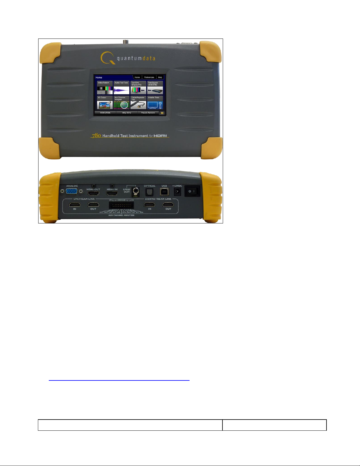
1.3 Introducing the 780 Handheld Test Instrument
The 780 Handheld Test Instrument is a battery-powered, portable multimedia pattern generator that enables
you to conduct quick, on-site verification testing of your HDMI system and analog video displays. The 780 is
equipped with both a reference source and a reference sink HDMI interface allowing you to test audio, video
and protocols—HDCP, EDID, CEC & infoframes—of any type of HDMI device: sources, repeaters and sinks. Its
portability makes it ideal for your bench and for use in the field. Because the 780 has both an HDMI output and
an HDMI input, you can test your HDMI cables and systems with splitters, extenders and switches as well with
the optional pixel error rate test feature.
A color touch display makes the 780 easy and convenient to use. When testing an HDMI source device you
can toggle between operating the unit through the touch screen and viewing the incoming video from the HDMI
source.
Page 5
780 Handheld Test Instrument – User Guide Page 4
May 15, 2012
Revision A28
Note: Image above shown with optional hardware board for passive HDMI monitoring between an HDMI source
and sink device.
1.4 Overview of 780 features
The 780 Handheld Test Instrument for HDMI provides a rich set of features. The following is a list of available
options and the key features and benefits of each:
1.4.1 Standard features
The following features are standard with the 780:
Pattern testing for HDTVs - Enables you to conduct pattern testing for an HDTV through the HDMI and
analog component outputs. Provides dozens of patterns with variation options on most.
Custom bitmaps and pattern scrolling – The 780 enables you to import bitmaps for use in pattern testing.
You can initiate a scroll of these bitmaps with user control over the rate and extent of horizontal movement.
Create custom formats using the standalone Format Editor.
3D bitmap pattern testing – The 780 enables you to import 3D bitmaps for use in pattern testing. You can
create your own bitmaps from any stereoscopic images you have using the Quantum Data Bitmap
Conversion Tool available from the Quantum Data website:
http://www.quantumdata.com/apps/3D/BMP_conv.asp. There are some sample 3D bitmaps on this
webpage as well.
Video confidence test of an HDMI source device – The 780 enables you to view the incoming video on the
780’s LCD screen.
Audio testing for AVRs and HDTVs – The 780 provides multi-channel digital audio test patterns through the
HDMI, SPDIF and optical outputs. A variety of audio patterns and formats are provided at sampling rates
Page 6

780 Handheld Test Instrument – User Guide Page 5
May 15, 2012
Revision A28
from 32kHz up to 192kHz and bit depths of 16, 20 and 24. Format supported are Dolby Digital and DTS
compressed formats and lossless compressed or high bit rate HDMI formats.
Installer Utility – Provides simplified diagnostics of HDMI interoperability problems in an HDMI installation.
The Installer utility enables installers to connect the 780 into an HDMI network and quickly conduct
diagnostics without required detailed knowledge of HDMI protocols.
Command line interface for automated testing.
1.4.2 Network Analyzer features
The following features are available with the Network Analyzer option:
HDCP test of an HDMI sink or input to a repeater device – The 780 enables you to run an HDCP functional
test on an HDMI sink device directly or through a repeater device.
EDID test of an HDMI HDTV or input to a repeater device – The 780 enables you to run an EDID functional
test on an HDMI sink device directly or through a repeater device. You can view the entire EDID in human
readable text. You can also run a portion of EDID compliance test.
Video test of an HDMI source device – The 780 provides an HDMI input for testing HDMI source devices.
You can run a verification test of a video source which includes timing and format information and an
indication of whether the video is HDCP content protected.
Data Island test of an HDMI source device – The 780 provides an HDMI input for testing HDMI source
devices. You can view the infoframes and other data islands.
Audio test of an HDMI source device – The 780 provides an HDMI input for testing HDMI source devices.
You can run a verification test of an audio source which includes decoding of the audio IEC headers, audio
infoframes and audio sample packet headers including parsing out of the channel status bits.
EDID test of an HDMI source device – The 780’s HDMI input can be provisioned with any EDID you have
access to. You can verify that a source device responds properly to the provisioned EDID. The EDID could
be a known-good EDID or an EDID that you have created specifically for testing.
HDCP test of an HDMI source device – The 780 enables you to run a test to determine how many HDCP
devices an HDMI source can support during HDCP authentication.
CEC ping test of any HDMI device – The 780 enables you to run a CEC ping test on an HDMI device.
1.4.3 HDMI Cable and Repeater test features
The following features are available with the Cable and Repeater test option:
HDMI Cable & Repeater test – Because the 780 has both an HDMI input and an HDMI output, you can
loop a cable or entire HDMI distribution networks comprised of splitters, extenders, repeaters, switches,
etc. from the 780’s output to input and run a pseudo-random noise pattern test to determine pixel errors on
the TMDS lines. The feature also runs a continuity test on the DDC test pair, CEC bus, the +5V line and the
hot plug lead. The Repeater test also shows you the hot plug delay between the downstream side and the
upstream side and the pulse width. The Cable & Repeater Test enable you to test a cable, repeater or
distribution network if the source and sink ends are collocated. If the source and sink ends are not
collocated then you need to use the Frame Compare test described below.
HDMI Frame Compare test – Because the 780 has an HDMI input, you can emulate a sink and test a
distribution network at the sink end. The feature works by capturing a frame of video from the source and
then comparing that frame, pixel-by-pixel, to subsequent frames. Errors are shown along with the number
of frames tested which 10 frames.
1.4.4 Auxiliary Channel Analyzer for DDC monitoring features
The following features are available with the Auxiliary Channel Analyzer test options:
Page 7

780 Handheld Test Instrument – User Guide Page 6
May 15, 2012
Revision A28
Table 1-1: 780 Shipping Box Contents
Item Description
Part No.
780 Handheld Test Instrument for HDMI.
00-00226
12V DC (1.5 amp) Power Supply / Adapter / Charger.
25-00094
Line cord for 12V Power Supply.
30A00400A03
HDMI-to-HDMI Type A cable.
30-00146
Three (3) foot VGA to (3) RCA adaptor cable.
99-00503
Six (6) foot USB cable.
30-00163
Quick Start Guide.
68-00217
DDC monitoring with Auxiliary Channel Analyzer (ACA) – The 780 ACA enables you to monitor CEC DDC
transactions such as HDCP and EDID as well as hot plug related events while emulating an HDMI source
and/or an HDMI sink device(s) in an HDMI system.
DDC passive monitoring with Auxiliary Channel Analyzer (ACA) – The 780 ACA enables you to monitor
CEC and DDC transactions throughout an HDMI systems comprised of a source, repeater and sink. You
can monitor +5V, hot plug events as well as the HDCP and EDID transactions.
1.4.5 What is in the 780 shipping box
The 780 instrument shipping container includes the items listed in Table 1-1 below:
Page 8

780 Handheld Test Instrument – User Guide Page 7
May 15, 2012
Revision A28
Table 2-1: 780 Video Interfaces
Video Interface
Description
HDMI (1) Output Type A
Single link HDMI output connector. Supports HDMI 1.3:
Bit Depth: 24/30/36 bit.
Colorimetry: RGB, YCbCr.
Sampling: 4:4:4 and 4:2:2.
Pixel rate: Timings up to 1080p60.
DVI support through HDMI to DVI adapter cable (RGB, 4:4:4, 24 bit).
Audio: LPCM, Dolby Digital and DTS (more details below).
Analog Output – Component and VGA (HD15F)
Bit Depth: 24 bit color depth.
Colorimetry: RGB, YPbPr.
Pixel rate: 80MHz.
Sync types: separate and composite.
HDMI (1) Input Type A
(Optional Feature Package)
Single link HDMI input connector. Supports HDMI 1.3:
Colorimetry: RGB, YCbCr.
Sampling: 4:4:4 and 4:2:2.
Pixel rate: Timings up to 1080p60.
2 Physical Interfaces of the 780 Handheld Test Instrument for HDMI
This section describes the administration, video and audio interfaces on the 780 test instrument:
2.1 Video Interfaces
Table 2-1 below describes the video interfaces on the 780 test instrument, these interfaces are used to render
test patterns for testing consumer electronic HDTVs and computer displays.
Page 9
780 Handheld Test Instrument – User Guide Page 8
May 15, 2012
Revision A28
Table 2-2: 780 Audio Interfaces
Interface
Description
HDMI (1) Output Type A
Single link HDMI output connector. Supports HDMI 1.3:
Channels: 8.
Bits per sample: 16, 20, 24.
Sampling rates (kHz): 32.0, 44.1, 48.0, 88.2, 96.0, 176.4, 192.0.
Formats: LPCM, Dolby Digital (clips), DTS (clips)
SPDIF - RCA
SPDIF RCA audio connector:
Channels: 8 (clips)
Bits per sample: 16, 20, 24.
Sampling rates (kHz): 32.0, 44.1, 48.0, 96.0
Formats: LPCM, Dolby Digital (clips), DTS (clips)
Optical – JIS FOS
Optical audio connector:
Channels: 8 (clips)
Bits per sample: 16, 20, 24.
Sampling rates (kHz): 32.0, 44.1, 48.0
Formats: LPCM, Dolby Digital (clips), DTS (clips)
2.2 Audio interfaces
Table 2-2 below describes the audio interfaces supported on the 780 test instrument.
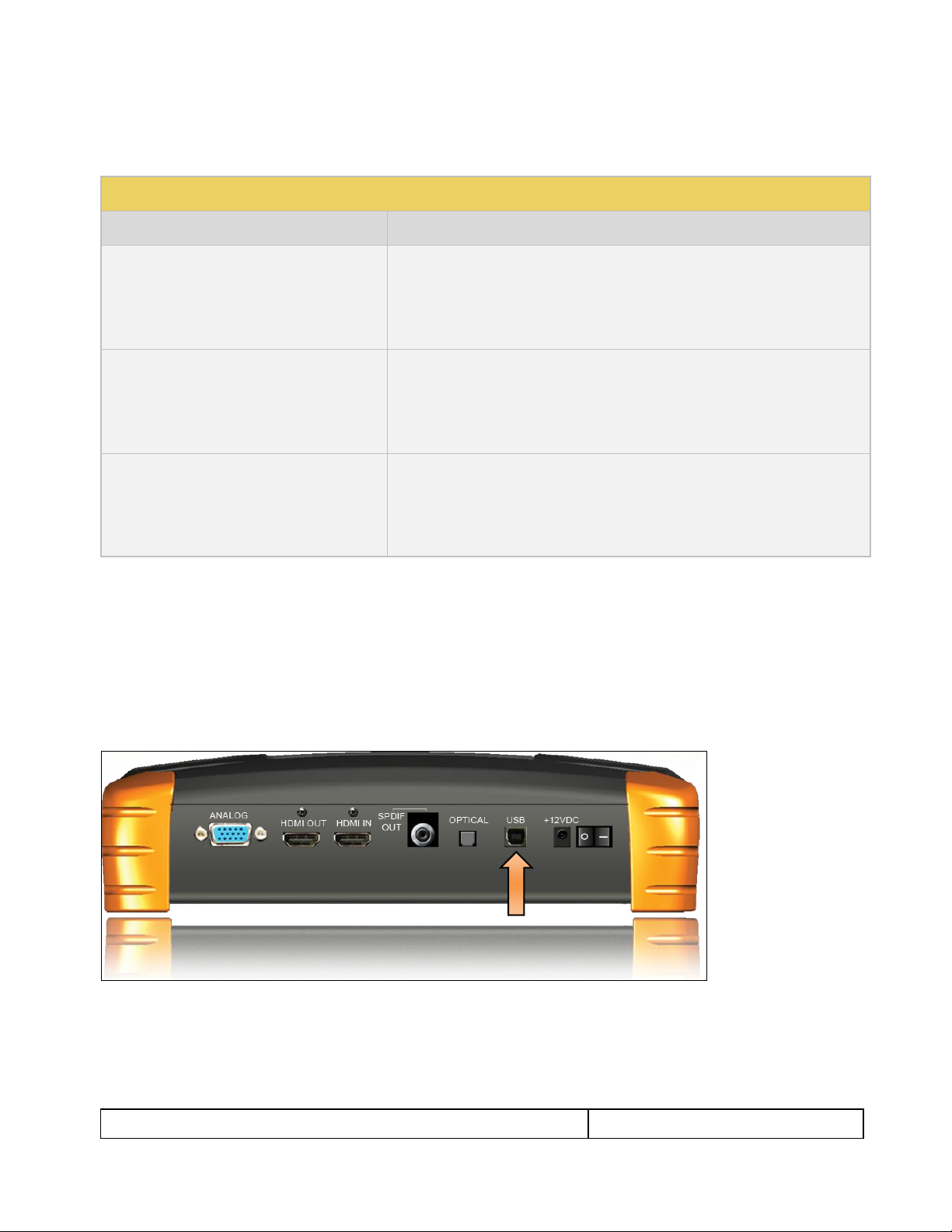
2.3 Administrative Interface
The 780 test instrument is equipped with a USB interface. This interface is used to download custom bitmaps
and to upgrade firmware and issue commands. The USB interface is a peripheral device. There are two modes:
COM - Command Mode. Used for sending basic commands to set the interface, select formats and
patterns.
Disk - Mass Storage Mode. Used for downloading bitmaps, audio clips and upgrading firmware or
gateware.
Page 10
780 Handheld Test Instrument – User Guide Page 9
May 15, 2012
Revision A28
3 General Operation
This section describes power up, power usage and general operation.
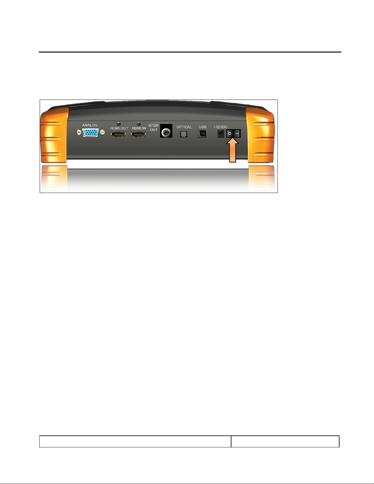
3.1 Power Considerations
The 780 has a rocker style power switch on the back panel. Refer to the photo below.
The 780 is a portable battery powered test instrument. It is equipped with nickel metal hydride batteries.
Typically, you can use the 780 on batteries for about 4 hours. It requires an overnight charge. Quantum Data
recommends that you set the screen brightness to the minimum level required. Turn the unit off if you are not
going to be using it for extended periods.
The 780 is supplied with the Part No 25-00094 12V DC power supply and charger as well as a part number
30A00400A03 line cord. We recommend that you use the 780 with the charger and only use the batteries
when power is not available.
Important Notes about power usage and status:
Monitor the battery meter on the lower right.
The screen will automatically dim after 2 minutes of inactivity to save on battery life.
A green indication or partial green indication shows the battery is being charged.
A gold color indicates that the device is being powered through the wall charger.
Fully charge the 780 overnight.
You must touch an active portion of the LCD to update the battery indicator to show its power status.
Do not continue using the 780 from battery power when the battery meter indicates that the batteries
are exhausted. When you see a thin green line at the right most portion of the battery icon, turn the
power off and switch to line power using the AC Charger adapter; then reapply power.
Page 11
780 Handheld Test Instrument – User Guide Page 10
May 15, 2012
Revision A28
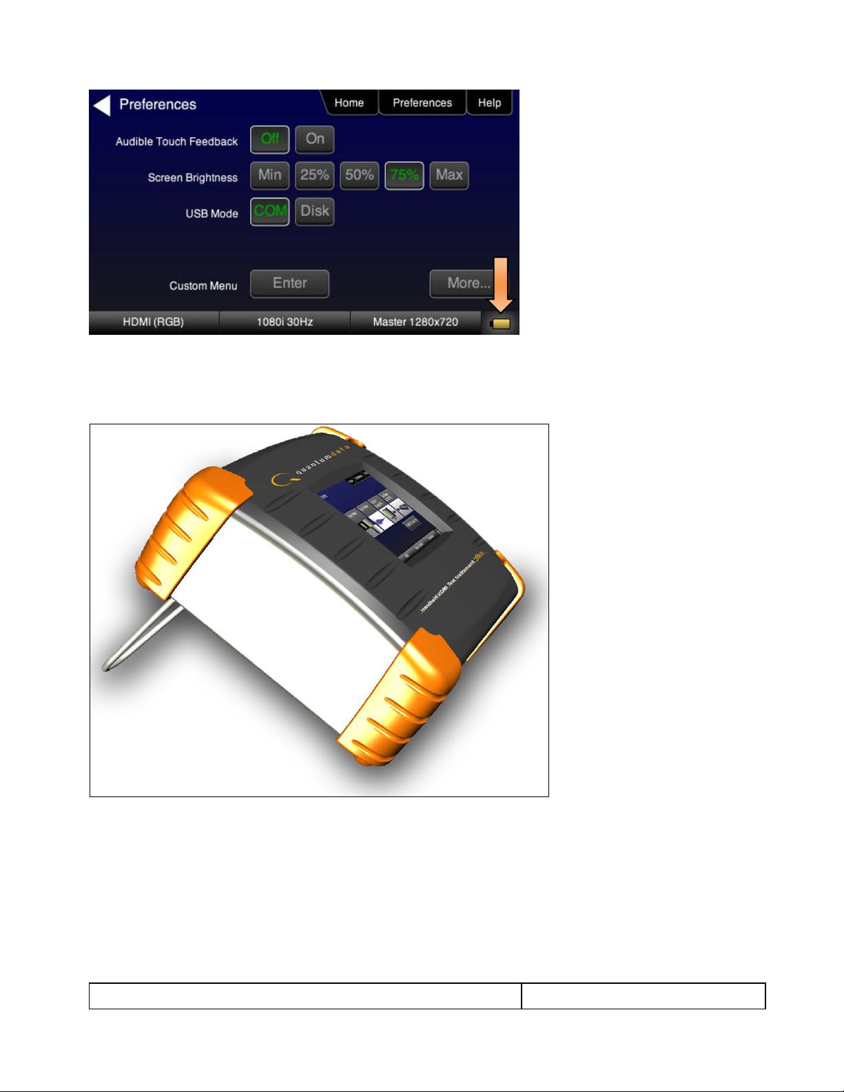
3.2 Tilt Bail
The 780 has support bail for convenience in viewing. This is depicted in the illustration below.
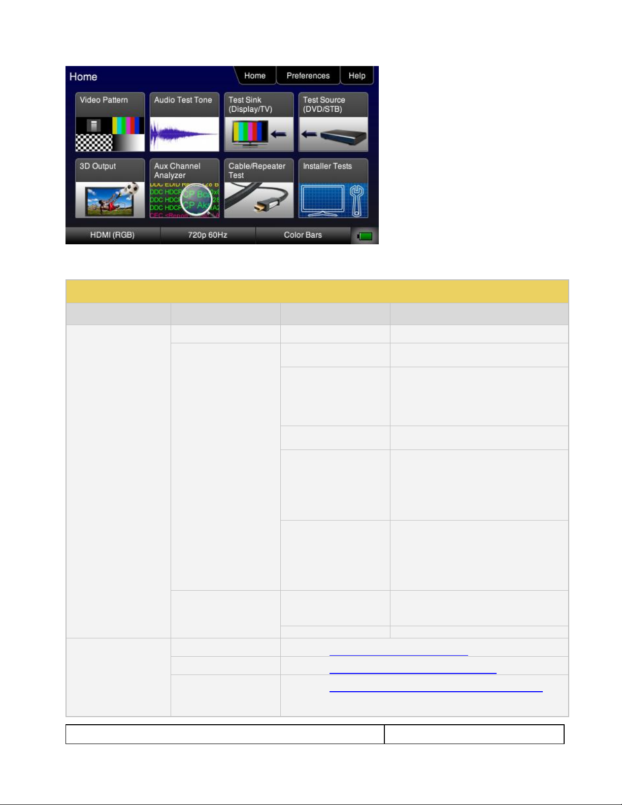
3.3 Navigating through the 780 User Interface
The 780 user interface is a color touch screen display 480 by 272. A single touch will activate an item on the
screen or take you down to a lower level menu. A + indicates that you have to double touch to navigate down to
a lower level menu.
Note: The top level menu will appear differently depending on what options have been purchased.
Page 12
780 Handheld Test Instrument – User Guide Page 11
May 15, 2012
Revision A28
Table 3-1: Top Level Menu
Item
Submenu - Pattern
Third Level Menu
Value
Top Menu Bar
Home
See Below
N/A
Preferences
Audible Touch
Off
On
Screen Brightness
Min
25%
50%
75%
Max
USB Mode
COM for commands
Disk for downloading files and upgrades
Hot Plug Mode
On – 804 automatically select the
formats in the EDID of the connected
HDTV.
Off – 804 will not automatically select
the formats in the EDID of the
connected HDTV.
AVMute
On – AVMute will occur when the
resolution is changed on the 780 HDMI
output.
Off – AVMute will occur when the
resolution is changed on the 780 HDMI
output.
Help
Upgrades
USB Storage Flash
Application Flash
FPGA Flash
Touchscreen
Calibrate the touch screen display
Function Buttons
Video Pattern
See below: Rendering Test Patterns on an HDTV
Audio Test Tone
See below: Testing Digital Audio of an HDMI Sink Device
Test Sink (Display/TV)
(with Network Analyzer
option)
See below: Using the 780 Test Instrument to Test HDMI Sink Devices
Table 3-1 below shows functions available in the top level menu.
Page 13
780 Handheld Test Instrument – User Guide Page 12
May 15, 2012
Revision A28
Test Source (DVD/STB)
(with Network Analyzer
option)
See below: Using the 780 Test Instrument to Test HDMI Source Devices
3D Output
See below: Rendering 3D Test Patterns on an HDTV
Auxiliary Channel
Analyzer
See below:
Procedures for Monitoring Auxiliary Channel events and transactions
Cable/Repeater Test
See below:
Using the 780 Test Instrument to Test HDMI Cable or Repeaters
Installer Tests
See below:
Procedures for Installer Utility
Bottom Status Buttons
Signal Type
See below: Using the 780 Test Instrument Installer Utility
Resolution
See below: Selecting a Signal Type and Resolution
Video Pattern
See below: Rendering Test Patterns on an HDTV
Battery Icon
See: Power Considerations
3.4 Calibrating the LCD
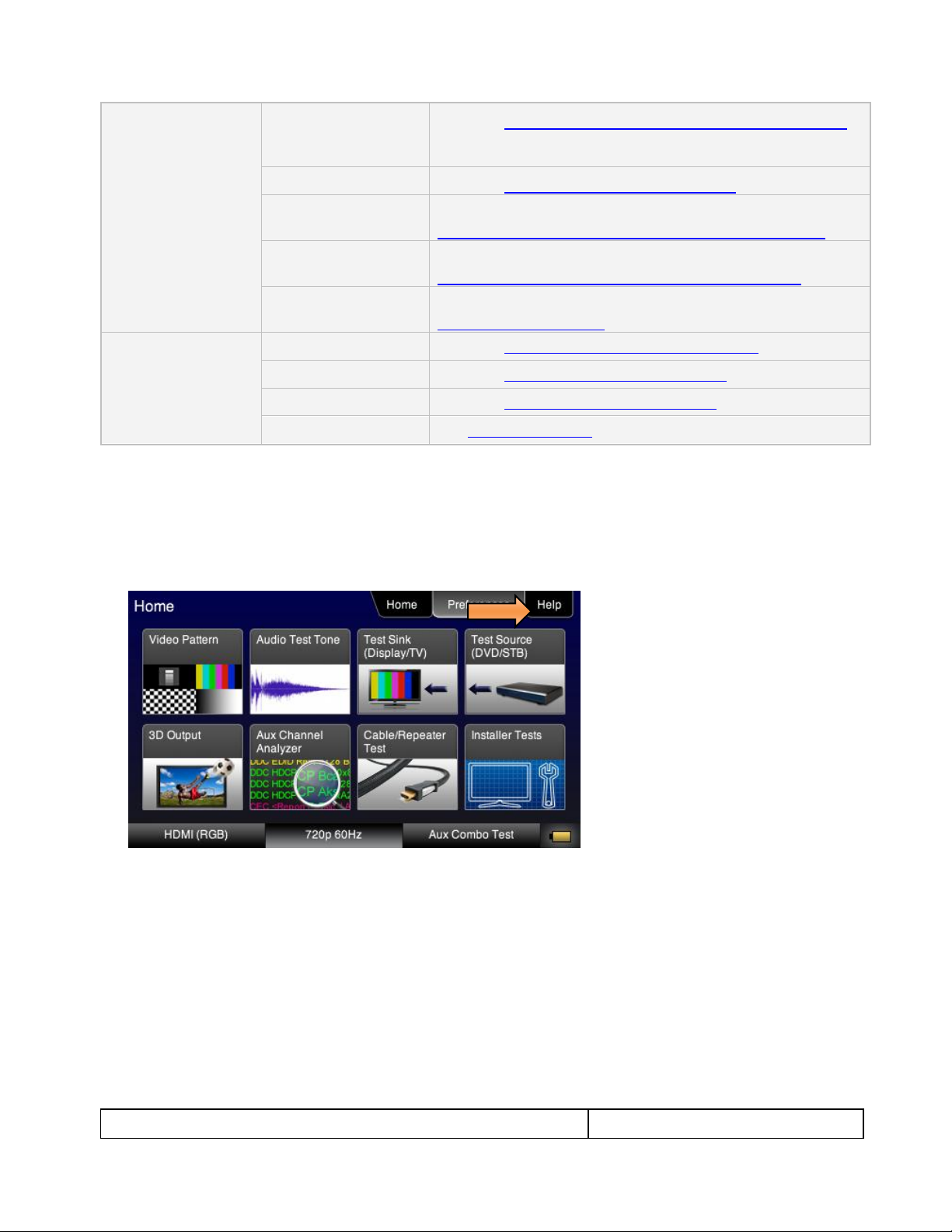
It is recommended that you calibrate the LCD display prior to using the 780 Test Instrument. Use the following
procedures to perform the calibration.
1. From the Home menu, navigate to the Help menu by pressing the Help activation button on the upper
status bar. The Home menu is shown below.
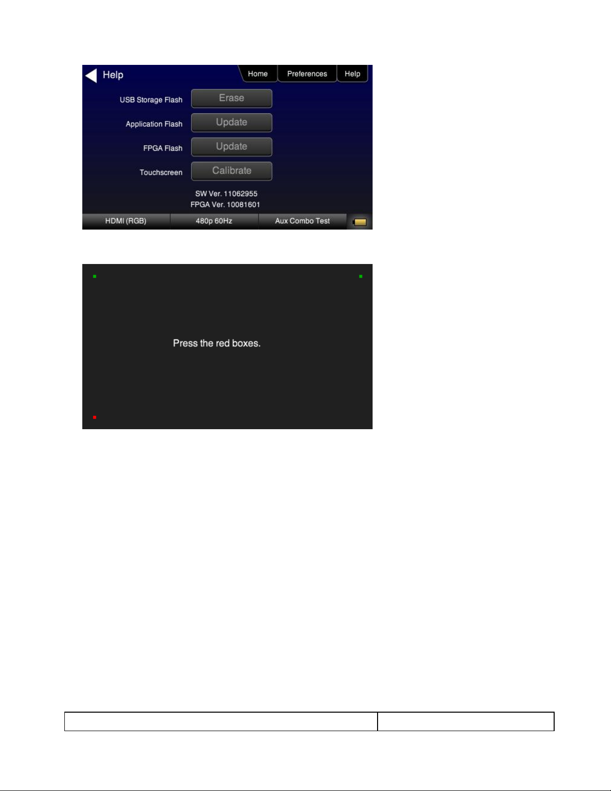
The Help menu appears as shown below:
Page 14
780 Handheld Test Instrument – User Guide Page 13
May 15, 2012
Revision A28
2. Touch select the Calibrate activation button. A screen appears instructing you to press each of four red
squares.
When you finish touch selecting the fourth box, the calibration is completed and you will return to the Home
menu.
Page 15
780 Handheld Test Instrument – User Guide Page 14
May 15, 2012
Revision A28
4 Using the 780 Test Instrument to Video and Audio Pattern Tests on
Sink Devices
This chapter provides procedures for running audio and video pattern tests on high definition sink devices such
as HDTVs and projectors. The features and functions described in this chapter are provided with the standard
780; no options are required. The following signal types are supported.
HDMI (via the HDMI physical connector)
DVI (via the HDMI physical connector)
YPbPr Component analog (via the HD VGA connector)
RGB Analog (via the HD VGA connector).
4.1 Making Physical Connections
The first step in testing a sink device is to make the physical connections between the 780 and the device(s)
under test.
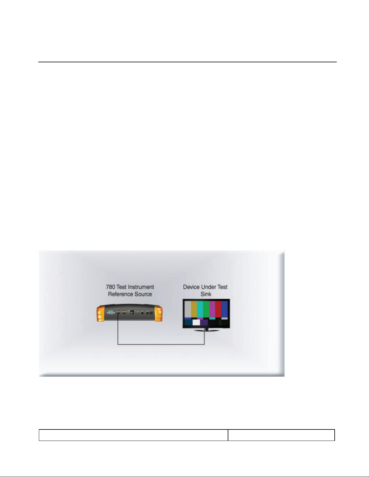
4.1.1 Connecting the 780 to the Display Device
Use the following procedures to make the physical connections from the 780 to the display device under test.
1. Make the cable connection between the appropriate the 780 video output connector (e.g. HDMI OUT or
ANALOG) connector and the input connector of the HDTV using the cables supplied.
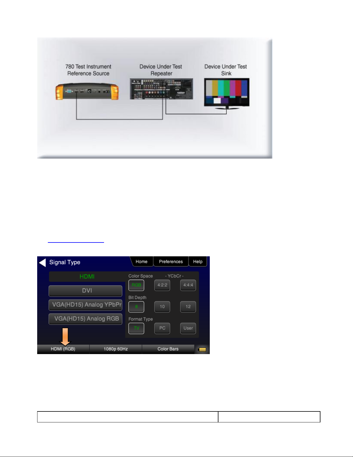
2. Alternatively you may connect from the 780 video output connector to an HDTV through an HDMI repeater
device such as an A/V receiver. In this case make the HDMI connection between the HDMI OUT connector
on the 780 and the HDMI input of the HDMI repeater device using an HDMI-to-HDMI cable. Then connect
the HDTV to an active output on the repeater. The following illustrations depict the typical test
configurations.
Page 16
780 Handheld Test Instrument – User Guide Page 15
May 15, 2012
Revision A28
4.2 Selecting a Signal Type and Resolution
After making the physical connections between the 780 and the display device under test you will need to
select the signal type, Resolution and Frame Rate for the sink device under test.
4.2.1 Procedures for Selecting a Signal Type
The procedures below describe how to select the active signal type.
1. Power up the 780 using the rocker switch on the back panel. Review the guidelines for battery usage at:
Power Considerations.
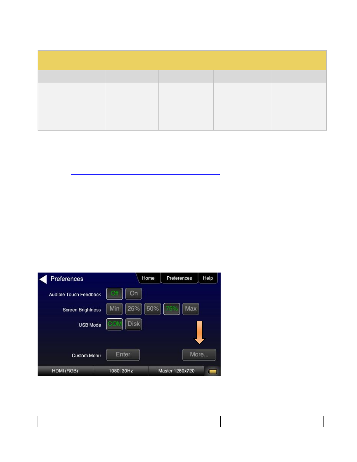
2. Touch select the Signal Type activation button on the panel on the left (see screen example below).
3. Touch select the desired signal type using the associated activation button.
4. Touch select the options for the Signal Type. Use the information in Table 4-1 below as a guide:
Page 17

780 Handheld Test Instrument – User Guide Page 16
May 15, 2012
Revision A28
Table 4-1: Signal Type
Signal Type Name
Physical Connector
Option
Option Values
HDMI
HDMI OUT via HDMI to
HDMI cable (provided)
Color Space
YCbCr
YCbCr 4:2:2
RGB
Bit Depth
8
10
12
Format Type
TV
Computer
User
DVI
HDMI OUT via HDMI to DVI
cable (not provided)
Format Type
TV
Computer
User
YPbPr Analog
ANALOG HD-15 (VGA) via
HD to 3-RCA cable
(provided)
Sync Type
Sep[arate] Sync
Sync on Green
RGB Analog
ANALOG HD-15 (VGA) via
VGA cable (not provided)
Format Type
TV
Computer
User
Sync Type
Sep[arate] Sync
Sync on Green
Table 4-2: HDTV (Consumer) Formats – Applies to HDMI, DVI (TV) and Analog YPbPr
Resolution
Frame Rates
Color Space
Sample Mode
Bit Depth
1080p (1920x1080)
1080i (1920x1080)
720p (1280x720)
576p (720x576)
576i (720x576)
480p (720x480)
480i (720x480)
24Hz
25Hz
29.97Hz
30Hz
50Hz
59.94Hz
60Hz
100Hz
119.88Hz
120Hz
YCbCr (HDMI)
YPbPr (Analog only)
RGB
4:4:4 (HDMI, DVI, YCbCr
only)
4:2:2 (HDMI only)
8
10 (HDMI only)
12 (HDMI only)
5. Use the information in Tables 4-2 and 4-3 below to select the proper video signal.
Page 18
780 Handheld Test Instrument – User Guide Page 17
May 15, 2012
Revision A28
Table 4-3: Partial List of Computer Formats – Applies to DVI Computer and Analog RGB Video Signal
Types
Resolutions
Name
Color Space
Sample Mode
Bit Depth
640x480
800x600
1024x768
1280x768
1280x1024
1600x1024
1920x1200
VGA
SVGA
XGA
WXGA
SXGA
WSXGA
WUXGA
RGB
4:4:4 (DVI)
8
4.2.2 Procedures for Selecting an HDMI Resolution and Frame Rate
The procedures below describe how to select the resolution in HDMI.
Note: You can create your own custom formats using the Quantum Data Format Editor. These procedures are
described in Creating and Using Custom Formats, EDIDs and Bitmaps.
When you make a physical connection to an HDMI HDTV, a hot plug event will occur. There are two modes the
780 can be set in when testing HDMI sink devices that determine how the 780 responds to this hot plug event:
1) Hot plug formats On; 2) Hot plug formats Off.
When hot plug formats are On and a hot plug event occurs, the 780 will read the EDID of the display device
connected to its output port. It will then automatically configure the list available signal types (resolutions and
frame rates) to only those supported by the HDMI sink device. The 780 will also be configured to output the
signal indicated in the EDID as the “preferred” timing. The preferred timing is highlighted in green following a
hot plug event.
When hot plug formats are Off, the 780 will display all viable HDMI formats for the HDMI interface whether they
are supported by the display or not.
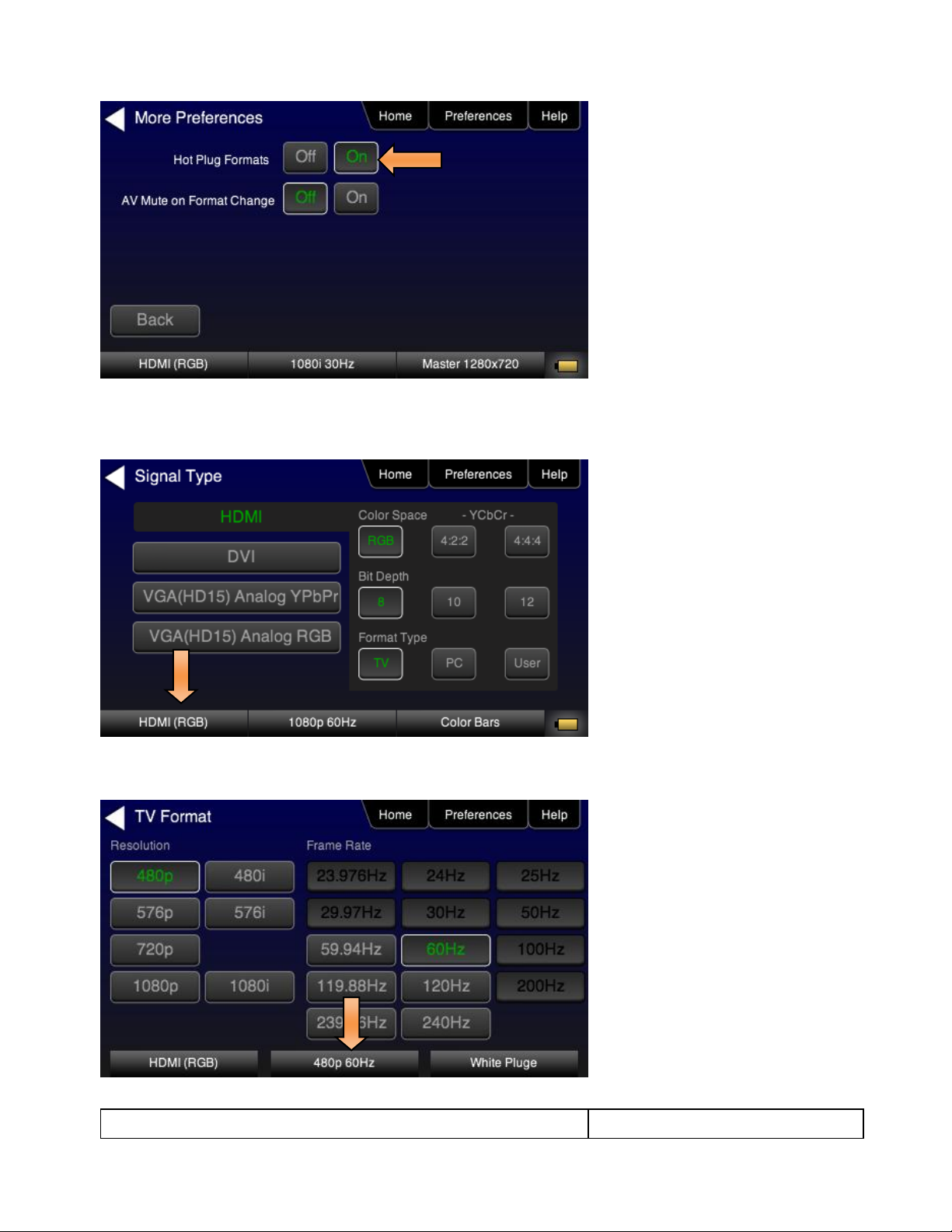
1. Select the Preferences from the 780 top level menu. Navigate to the second page by touch selecting the
More… key.
Page 19
780 Handheld Test Instrument – User Guide Page 18
May 15, 2012
Revision A28
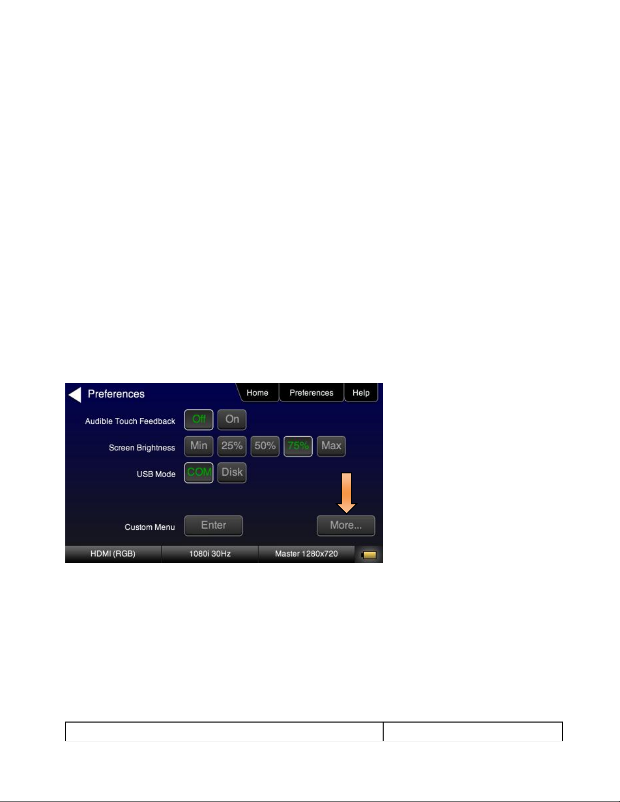
2. Select the Hot Plug Formats mode to On or Off as desired. Refer to the screen above.
3. Touch select the interface button (left button on the bottom panel). Refer to the figure below.
For the HDMI interface, you will set the Color Space, sampling mode, Bit Depth and Format Type.
4. Touch select the resolution and frame rate (middle button on the bottom panel). Refer to the figure below.
Page 20
780 Handheld Test Instrument – User Guide Page 19
May 15, 2012
Revision A28
For the HDMI formats, there are color codes that are applied to the Resolution and Frame Rate selections. The
following is a summary of their meaning:
A Resolution or Frame Rate with white lettering but with no outline – a Resolution or Frame Rate that
appears in the EDID and has a short video descriptor associated with it.
A Frame Rate with green lettering and with white outline – The Frame Rate that is currently selected.
A Frame Rate with red lettering but with no outline – The Frame Rate is not supported by the EDID for
that Resolution.
A Frame Rate(s) with green lettering and with white outline – The Frame Rate along with the currently
selected Resolution that is the “preferred” timing.
A Frame Rate with black lettering but with no outline – The Frame Rate is not supported by the standard
for the selected resolution.
Note: When you make a physical connection to an HDMI HDTV, a hot plug event will occur. If Hot Plug
Formats is enabled on the Preference menu, when the hot plug event occurs, the 780 will read the EDID
of the display device connected to its output port. The output is automatically set to the preferred timing
which is highlighted in green following a hot plug.
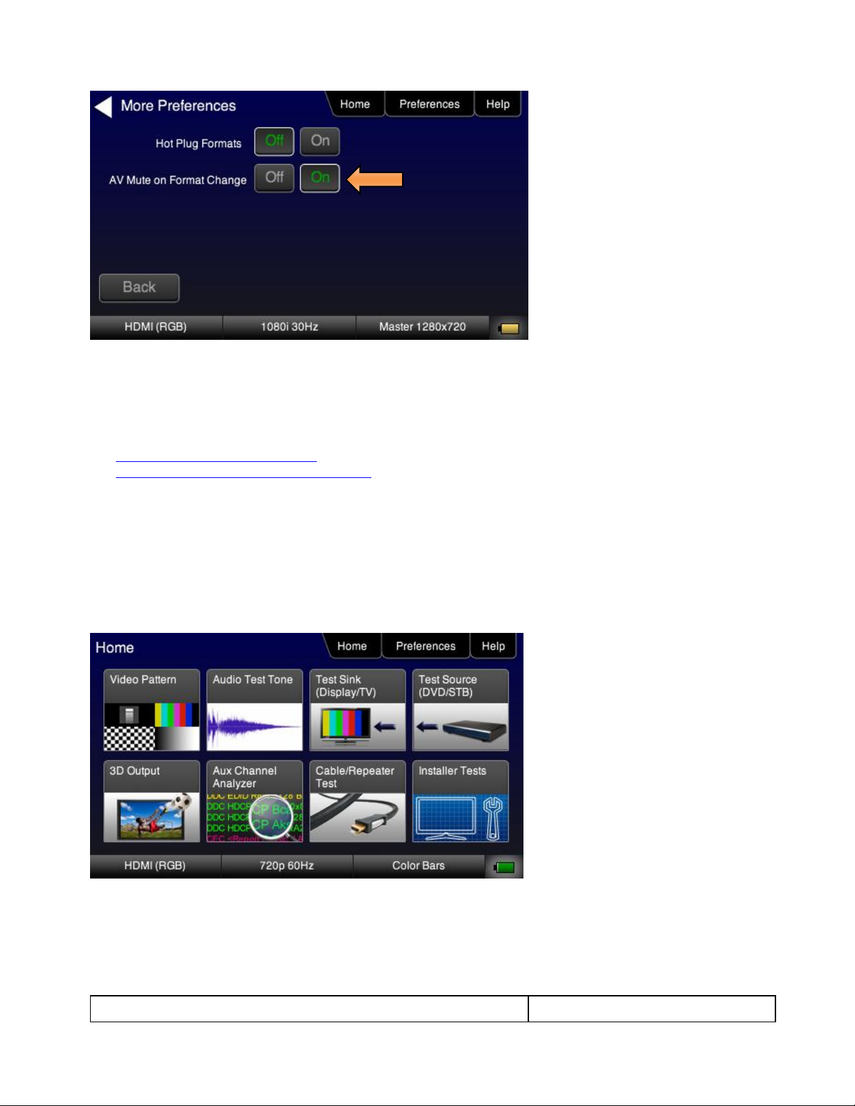
4.2.3 Procedures for Enabling AVMute
The procedures below describe how to enable AVMute. AVMute is an optional feature in HDMI that enables a
source to signal a sink to extinguish its audio and video. The source, in this case the 780 emulating a source
sets the AVMute Set flag in the general control packet. The purpose of AVMute is to avoid audio artifacts when
switching resolutions.
1. Select the Preferences from the 780 top level menu. Navigate to the second page by touch selecting the
More… key.
2. Touch select the On activation button next to AVMute on the screen below.
Page 21
780 Handheld Test Instrument – User Guide Page 20
May 15, 2012
Revision A28
4.3 Rendering Test Patterns on an HDTV
This subsection describes how to render test patterns on an HDTV. You will first have to complete the previous
procedures:
Making the physical connections
Selecting the Signal Type and Resolution
4.3.1 Procedures for Rendering Test Patterns on an HDTV
The procedures below cover cases where there is a direct connection between the 780 and the HDTV and also
where the 780 is connected to an HDTV through a repeater device.
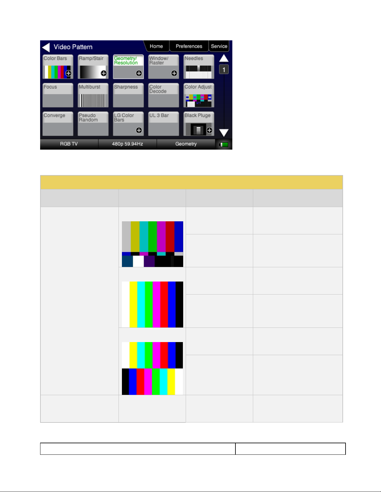
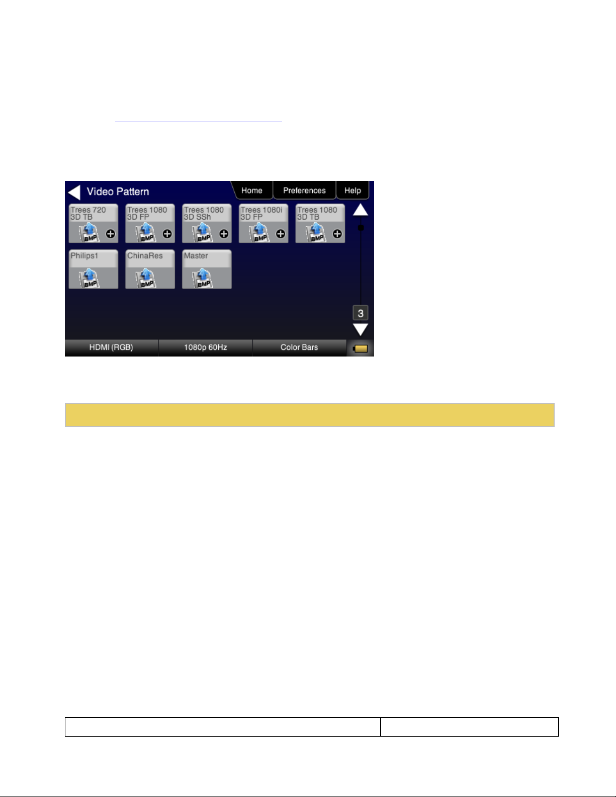
1. From the Home screen on the 780 display, touch select Video Pattern as shown below.
Note: Your Home screen may appear somewhat different depending on what options you have.
2. Touch select the desired test pattern from the menu shown below. You can select patterns that are
standard with the 780 or bitmaps that you have imported.
Note: A “+” on the lower right portion of the pattern indicates that there are options related to the specific
pattern. In these cases you double touch select to access the lower level menu.
Page 22
780 Handheld Test Instrument – User Guide Page 21
May 15, 2012
Revision A28
Table 4-3: Test Patterns
Pattern Name
Variant
Options
Range of Values
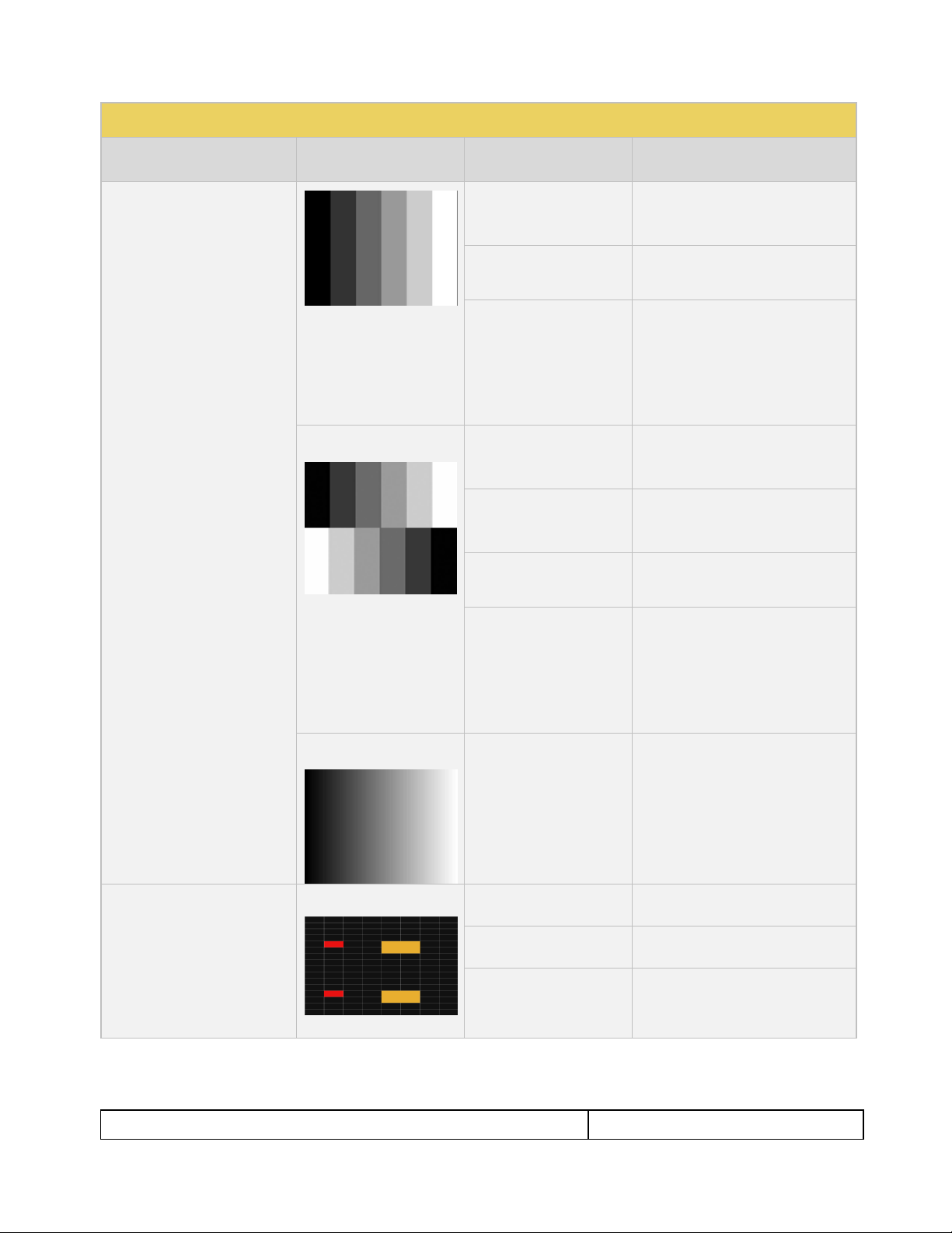
ColorBar patterns
Applications:
SMPTEBars - To adjust color
and hue.
Colorbars - To test a display’s
ability to product fully saturated
primary and secondary color.
SMPTE
Orientation - Vertical
Direction:
Left to Right
Right to Left
Orientation - Horizontal
Direction:
Top / Bottom
Bottom / Top
Full
Orientation - Vertical
Direction:
Left to Right
Right to Left
Orientation - Horizontal
Direction:
Top / Bottom
Bottom / Top
Split
Orientation - Vertical
Direction:
Left to Right
Right to Left
Orientation - Horizontal
Direction:
Top / Bottom
Bottom / Top
Ramp/Stair Patterns
Applications:
Stair - Full
Orientation - Vertical
Direction:
Left to Right
Right to Left
3. (If applicable) Specify the test pattern options. Use the information in Table 4-3 below as a guide.
Note: There may be additional patterns not shown in the table.
Page 23
780 Handheld Test Instrument – User Guide Page 22
May 15, 2012
Revision A28
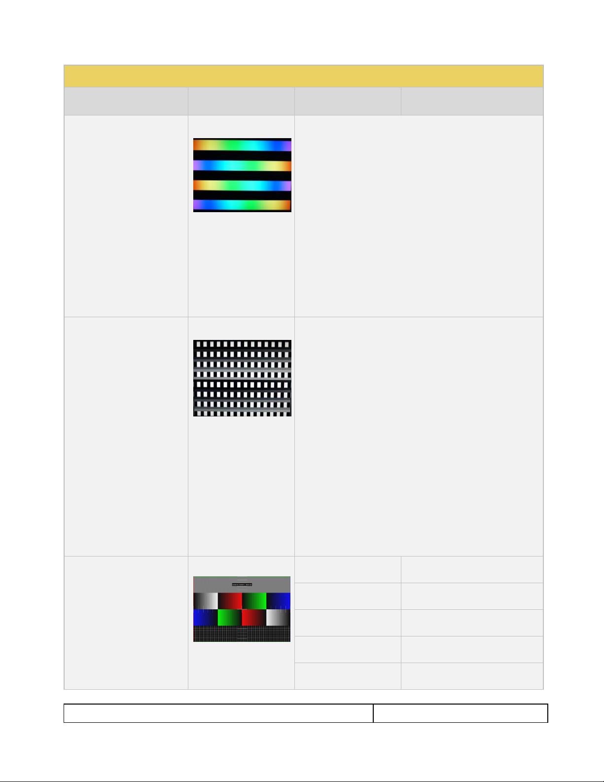
Table 4-3: Test Patterns
Pattern Name
Variant
Options
Range of Values
Stair - To visually check
grayscale tracking performance
of a rear projection display.
Ramp – To check the digitizing
linearity of video signal
processors.
Orientation - Horizontal
Direction:
Top / Bottom
Bottom / Top
Bars
5
11
21
Color
R
G
B
C
M
Y
W
Stair – Split
Orientation - Vertical
Direction:
Left to Right
Right to Left
Orientation - Horizontal
Direction:
Top / Bottom
Bottom / Top
Bars
5
11
21
Color
R
G
B
C
M
Y
W
Ramp
Color
R
G
B
C
M
Y
W
3D Box Pattern
Application: This is a 3D
pattern used to test 3D
displays. The pattern enables
you to set the offset between
the left and right image
components.
No variants
Box 1 Offset
-64 to +64
Box 2 Offset
-64 to +64
Background Brightness
0 to 63
Page 24
780 Handheld Test Instrument – User Guide Page 23
May 15, 2012
Revision A28
Table 4-3: Test Patterns
Pattern Name
Variant
Options
Range of Values
3D Color Ramp
Application: This is a 3D
pattern used to test 3D color
uniformity and crosstalk or
extinction ratio.
No variants
Description: There are 4 pairs of horizontal color bars. Each bar
depicts a color gradation from red to purple; two from left to right
and one from right to left.
Method – Color uniformity:
1. Close left eye to view image from right eye.
2. Assess the color gradation on each bar.
3. Close right eye to view image from left eye.
4. Subjectively compare the images to assess color
uniformity.
Method – Crosstalk (extinction ratio):
1. Close left eye to view image from right eye.
2. Verify that the bottom bar is extinguished. The extent to
which the bar is not extinguished represents the amount
of crosstalk.
3. Repeat for a test of the left eye
3D Cross Talk
Application: This is a 3D
pattern used to measure the
crosstalk (extinction ratio) for
frame packing, top and bottom
and side by side 3D format
structures.
No variants
Description: This image is divided in two sections with four rows of
16 white boxes each. The top section is for testing with the left eye
open. The bottom section is for testing with the right eye open.
The background area surrounding the boxes is a series of
grayscale ramps. The ramps begin at 100 IRE and transitions to
50 IRE at the left end of the fourth row of each series.
Method – Calculating percent crosstalk:
1. Close right eye to test the left eye using the top section.
2. Check the visibility of the boxes. Any deviation from
black indicates crosstalk.
3. Assess where the box and its background blend such
that they are not distinguishable.
4. Calculate the degree of crosstalk as a percent by
counting the number of boxes (from the beginning of the
series to the box identified in step 3) and divide that by
127. Example if the 20th box blends with its background,
the crosstalk would be 20/127 * 100 = 15.7%
5. Repeat with the left eye closed to test the right eye.
PGCWRGB Pattern
Application: This is a scrolling
pattern used to test for noise
on analog displays and motion
artifacts.
No variants
Show Text
On / Off
Show Center Cross
On / Off
Show Video
On / Off
Show Overscan
On / Off
Grid Type
10x50
5% H/V
Page 25
780 Handheld Test Instrument – User Guide Page 24
May 15, 2012
Revision A28
Table 4-3: Test Patterns
Pattern Name
Variant
Options
Range of Values
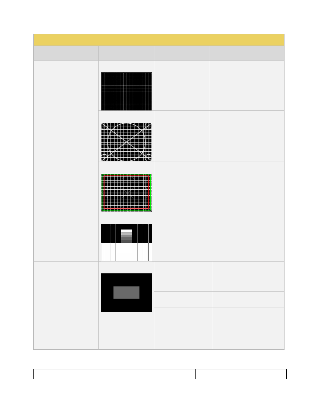
Geometry/Resolution
Patterns
Applications:
Grid – To check and adjust
convergence of red, green and
blue pictures.
Linearity – for testing deflection
linearity testing and alignment.
Overscan – To check and
adjust for the proper geometry
of display including picture
centering, size, pincushion and
linearity.
Grid Color Mode
White on Black
Black on White
Linearity
Color Mode
White on Black
Black on White
Overscan
N/A
Needles Pattern
Application: To detect whether
scan velocity modulation is
enabled on display.
No variants
Window/Raster Pattern
Applications:
Window1 - To calibrate display
drive chromaticity.
Window2 - To calibrate display
cutoff chromaticity.
Raster – To check color purity
and display chrominance
uniformity.
Window
IRE Level
-5
-1
100
+1
+5
IRE Label
Off
On
Color
R
G
B
C
M
Y
W
Page 26
780 Handheld Test Instrument – User Guide Page 25
May 15, 2012
Revision A28
Table 4-3: Test Patterns
Pattern Name
Variant
Options
Range of Values
Raster
IRE Level
-5
-1
100
+1
+5
IRE Label
Off
On
Color
R
G
B
C
M
Y
W
Needles Pattern
Application: To detect whether
scan velocity modulation is
enabled on display.
N/A
Focus Pattern
Application: To detect whether
scan velocity modulation is
enabled on display.
N/A
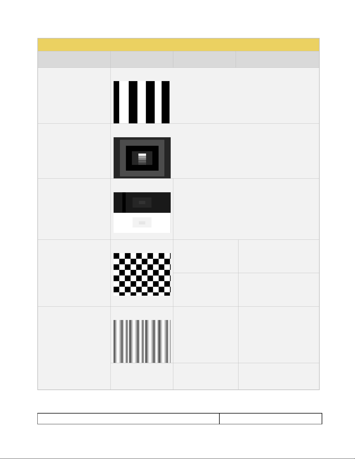
Multiburst Pattern
Application: To check a
display’s ability to produce
sharply defined stripes at equal
brightness up to full resolution.
N/A Sharpness
Application: To align display
sharpness, picture, aperature
and scan velocity modulation
adjustments.
No Variants
Page 27
780 Handheld Test Instrument – User Guide Page 26
May 15, 2012
Revision A28
Table 4-3: Test Patterns
Pattern Name
Variant
Options
Range of Values
Decoder Check
Application: To check the color
decoder performance to
determine if the decoder overemphasizes red or green
colors.
No Variants
Decoder Adjust Pattern
Application: To adjust a
display’s color decoder/matrix
circuit for most accurate color
reproduction.
No Variants
Converge Pattern
Application: To color converge
a display throughout the entire
picture area.
No Variants
Pseudo Random Pattern
Application: To test for pixel
errors on an HDMI cable.
No Variants
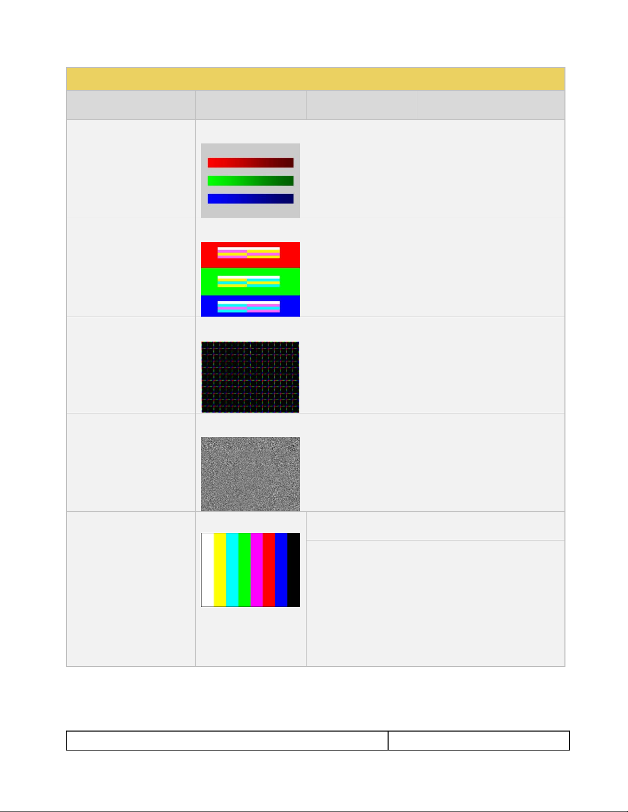
LG Color Pattern
Application: To test a display’s
ability to product fully saturated
primary and secondary color.
White is 100 IRE
Yellow is 100 IRE
Cyan is 100 IRE
Gray is 35 IRE
Red is 100 IRE
Blue is 100 IRE
Black is 0 IRE
No Variants
Horizontal
Vertical
Page 28
780 Handheld Test Instrument – User Guide Page 27
May 15, 2012
Revision A28
Table 4-3: Test Patterns
Pattern Name
Variant
Options
Range of Values
UL 3 Bar Pattern
No Variants
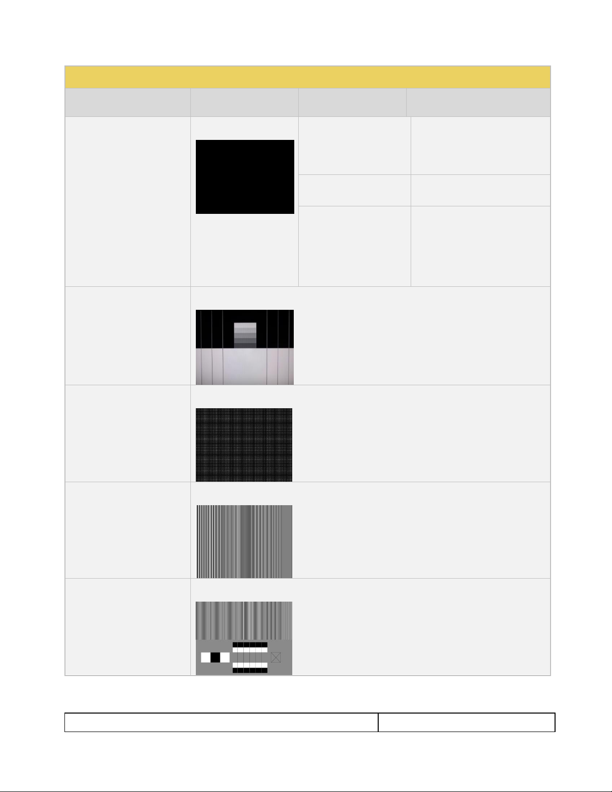
Black Pluge Pattern
Application: To set the picture
black level and check the DC
restoration performance of a
display.
No Variants
White Pluge Pattern
Application: To set the contrast
and brightness controls on
fixed pixel displays.
No Variants
N/A
Checkboard Pattern
Application: To check the
regulation of CRT video drive
power supply circuits.
No Variants
Rows
2
3
4
5
6
2
3
4
5
6
Zone Plate Pattern
This is a bitmap that can be
scrolled to test motion artifacts.
You can replace particular
bitmap with any other bitmap
image to allow scrolling. You
just need to ensure that you
assign it the same name.
Vertical
Stop
Slow
Medium
Fast
Horizontal Movement
Stop
Slow
Medium
Fast
Page 29
780 Handheld Test Instrument – User Guide Page 28
May 15, 2012
Revision A28
Table 4-4: Custom Test Image Packs
4.4 Using Custom Test Image Packs
The 780 provides licensed image packs for certain sets of test images. You need to have a license key to use
these custom test image packs. You can arrange to get access to them by contacting Quantum Data customer
support at: http://www.quantumdata.com/support.
When you purchase an image pack it appears as an icon at the end of the list of Test Patterns. A sample
screen is shown below (Philips1, ChinaRes, Master). You simply select one of the test patterns (e.g. ChinaRes
in the screen example below). They will take a few seconds to load. They will load at the resolution of the
format that you have selected.
Refer to the table below for a description and depiction of the Image Packs currently offered.
Page 30
780 Handheld Test Instrument – User Guide Page 29
May 15, 2012
Revision A28
Table 4-4: Custom Test Image Packs
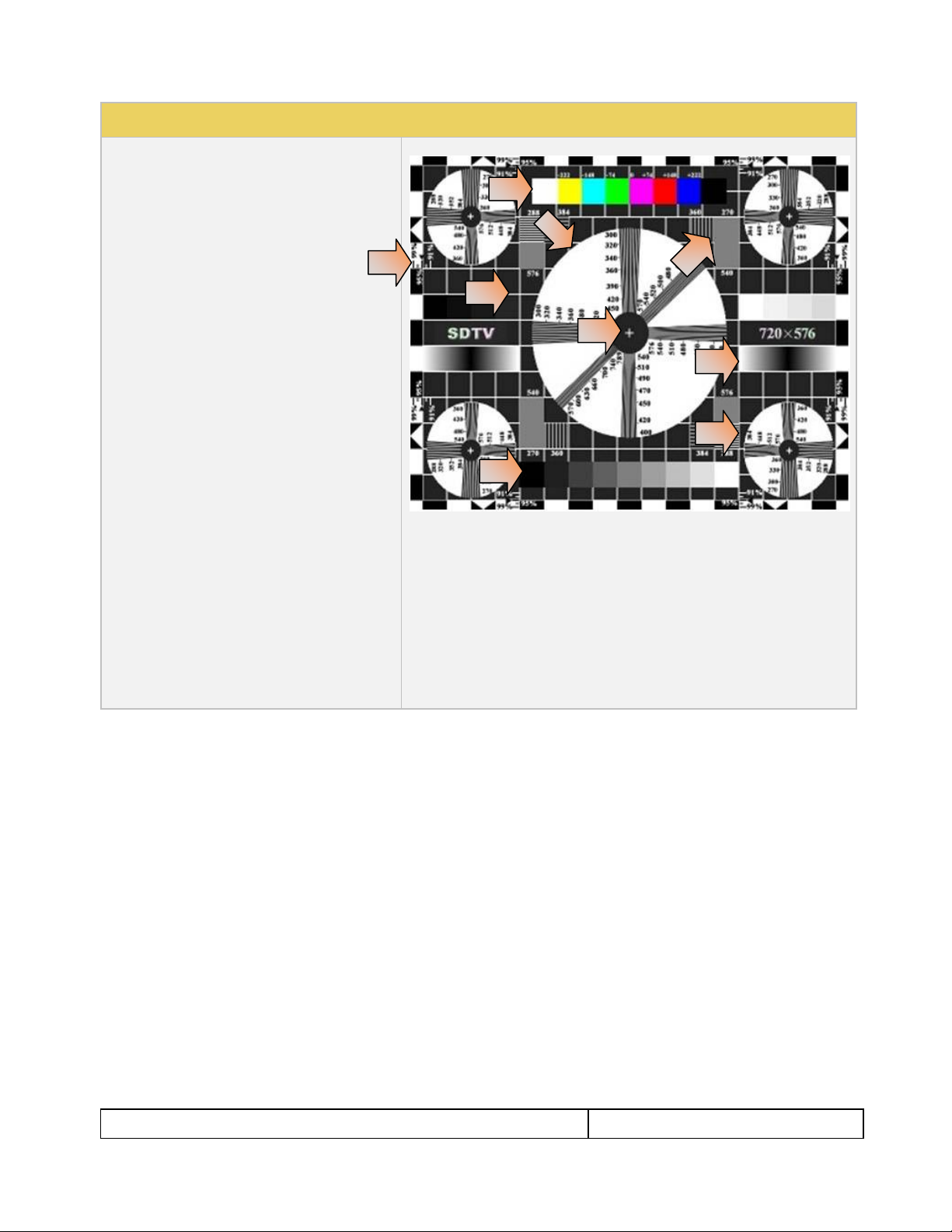
ChinaRes Pattern Pack
This is a bitmap that is available through the
Image Packs option. The ChinaRes test pattern is
specified by the National Testing and Inspection
Center for Radio and TV Products of China.
The image pack includes both a standard
definition aspect ratio (shown right) and a high
definition aspect ratio. This test pattern is
supported at: 1920x1080, 1280x720, 720x576
and 720x480 resolutions.
The following is a description of the elements in
this test image
1. Overscan gauges to determine percentage of
overscan.
2. Centered cross, centered circles, and centered
grid to test centering and concentricity.
3. White grid to test convergence.
4. Central resolution wedge gauges for vertical,
horizontal, and diagonal resolutions.
5. Corner resolution wedge gauges for vertical and
horizontal resolutions.
6. 4-quadrant horizontal and vertical test areas to
judge resolution and display artifacts.
7. Color bar for testing color purity and chroma
delay.
8. 10-step grayscale to test brightness, contrast, and
luminance.
9. Split (left and right) grayscales for testing dark-
field and bright-field gray levels.
Average picture level is approximately 50%.
1
2
3
6
7
8
9
4.5 Rendering 3D Test Patterns on an HDTV
This subsection describes how to render 3D test patterns on an HDTV. The 780 supports Side-by-Side, Topand-Bottom and Frame Packing (for both interlaced and progressive timings) 3D format structures.
4.5.1 Configurations for Rendering 3D Bitmaps on an HDMI Sink Device
Typically you will render 3D bitmap images with the 780 directly connected to an HDTV. This configuration is
shown below:
Page 31

780 Handheld Test Instrument – User Guide Page 30
May 15, 2012
Revision A28
4.5.2 Procedures Obtaining 3D Bitmaps on HDMI Sink Device
Use the procedures below to render 3D bitmap images on an HDMI sink.
1. Follow the procedures provided above to enable the HDMI output as the Signal Type.
2. Obtain 3D bitmaps. You can obtain 3D bitmaps in three ways:
Develop your own 3D bitmaps.
Sample 3D bitmaps from the Quantum Data website (www.quantumdata.com/downloads).
Generate 3D bitmaps from your own stereoscopic image pairs using the Quantum Data 3D Bitmap
Conversion Tool available from the Quantum Data website (www.quantumdata.com/downloads).
3. Transfer your 3D bitmaps over to the 780 using the procedures described in Importing Custom Bitmaps.
4.5.3 Procedures for Rendering 3D Bitmaps or 3D Test Patterns on HDMI Sink Device
1. Select a format that is suitable for rendering 3D images such as 720p60 and 1080. Use the procedures
above Procedures for Selecting an HDMI Resolution and Frame Rate.
If you have used the Quantum Data 3D Bitmap Conversion Tool, there is a naming convention for the 3D
bitmaps which also provides the required format for each specific bitmap.
2. Touch select 3D Output option from the top level menu shown below.
Page 32

780 Handheld Test Instrument – User Guide Page 31
May 15, 2012
Revision A28
The following screen will appear:
3. Select the 3D mode (Side-by-Side, Top-and-Bottom or Frame Packing) and then select the subtype and
Left/Right options (if applicable).
4. Select the 3D bitmap image from the Test Pattern list.
Note: You will have to make sure that the 3D bitmap you use matches your selection of 3D formats and
timing (resolution). In the example above, a 3D Frame Packing bitmap is selected for 1280 x 720.
Therefore you have to make sure that you select that specific timing (i.e. 1280 x 720) and that specific 3D
format structure (Frame Packing).
4.6 How to Scroll a Bitmap Pattern
This subsection describes how to scroll bitmaps on your 780
4.6.1 Guidelines for Scrolling Bitmaps
There are two ways you can animate (move) a bitmap image: 1) image shifting (scrolling); 2) panning. You can
shift or scroll a bitmap image that you have imported into the 780 by modifying the X and Y parameters or by
dragging and panning. When you use the X and Y parameters, you are limited to linear scrolling. With panning
you can move the image in non-linear motions.
Page 33

780 Handheld Test Instrument – User Guide Page 32
May 15, 2012
Revision A28
You can only scroll bitmaps whose overall pixel resolution is smaller than the resolution of the active format and
you can only scroll them within the bounds of the resolution of the active format. You cannot scroll the standard
test patterns in the 780.
In order to scroll a bitmap the name of the bitmap has to be “zp.bmp.” But you can scroll any bitmap. You just
have to make sure that you have named it “zp.bmp” (without the quotes). The zone plate bitmap is the only
bitmap that comes standard with the 780.
4.6.2 Procedures for Scrolling Bitmaps
Use the following procedure to scroll your bitmaps.
1. Touch select the desired bitmap image, e.g. Zone Plate image from the list of video patterns.
2. Double touch select on the Zone Plate bitmap to access its options.
The Zone Plate Options menu appears:
3. Specify the Horizontal Movement by touch selecting the appropriate setting Slow, Medium, Fast.
4. Specify the Vertical Movement by touch selecting the appropriate setting Slow, Medium, Fast.
The pattern will begin to move around the raster of the display in accordance with the horizontal and
vertical settings. To halt the motion, touch Stop for either or both of the Horizontal Movement and
Vertical Movement.
Page 34

780 Handheld Test Instrument – User Guide Page 33
May 15, 2012
Revision A28
4.7 How to Pan a Bitmap Image
This subsection describes how to pan bitmap test patterns on your 780
4.7.1 Guidelines for Panning Bitmaps
There are two ways you can animate a bitmap image: 1) image shifting (scrolling) 2) panning. Here are the
rules and capabilities:
You can pan bitmaps whose overall pixel resolution is greater than the resolution of the active format only
to the extent of the difference between the resolution of the bitmap and the resolution of the format you
currently have selected.
You can pan bitmaps whose resolution is lower than the active format but only within the range of the
excess space in the raster. You cannot pan the standard test patterns in the 780.
4.7.2 Procedures for Panning Bitmaps
Use the following procedure to pan your custom bitmaps.
1. Select by double touching, the desired bitmap image, e.g. Master 1920x1080 image from the list of video
patterns (shown below).
A message will appear informing you how to scroll the bitmap.
Page 35

780 Handheld Test Instrument – User Guide Page 34
May 15, 2012
Revision A28
2. Drag and pan the test pattern.
4.7.3 Procedures for Viewing the Video from an HDMI Source Device
Use the following procedures to view the incoming video from an HDMI source device.
1. Connect the HDMI source device under test to the 780 HDMI IN connector.
2. Touch select Test Source (DVD/STB) from the top level menu shown below.
3. Touch select Video Display from the Source Tests menu shown below.
4. Touch select the Start Fullscreen activation button on the Video Display menu to view the incoming video
without viewing the metadata from the source device under test.
Page 36

780 Handheld Test Instrument – User Guide Page 35
May 15, 2012
Revision A28
The video from the source is shown on the 780 LCD as depicted below.
Note that you can also view 3D video bitmaps as well. The following screen is a sample of what a 3D bitmap
would look like. The example below is a Top-and-Bottom format.
5. Touch select the screen to return to Video Display menu.
Page 37

780 Handheld Test Instrument – User Guide Page 36
May 15, 2012
Revision A28
6. Touch select the Start Fullscreen activation button on the Video Display menu to view the incoming video
along with the metadata from the source device under test. In this example a test pattern is shown.
Note also that the HDCP encryption status and AVmute status is shown. In addition to the AVI infoframe
values.
7. Return to the Source Test menu by touching the LCD. The Source Test menu reappears.
Page 38

780 Handheld Test Instrument – User Guide Page 37
May 15, 2012
Revision A28
Table 4-5: Summary of Audio Signal Types
Audio Signal Type
Interfaces
Description
Dolby 5.1
HDMI
Optical
SPDIF
Provides a set of Dolby Digital 5.1 noise patterns:
500-2kHz Pink
20-20kHz Pink
Sine Wave
Impulse
Polarity
Auto Time Delay
Dolby Digital Plus 7.1
HDMI
Provides a set of Dolby Digital Plus 7.1 sine wave clips:
2.0 192kHz – 2 channel @ 192kHz sampling rate
5.1 192kHz – 6 channel @ 192kHz sampling rate
7.1 192kHz – 8 channel @ 192kHz sampling rate
DTS-ES 6.1
HDMI
Optical
SPDIF
Provides a set of DTS ES 6.1 noise pattern clips:
500-2kHz Pink
20-20kHz Pink
Sine Wave
Impulse
Polarity
Auto Time Delay
Dolby TrueHD
HDMI
Provides a set of Dolby TrueHD Hi Bit Rate sine wave clips:
192kHz 7.1 1kHz TrueHD – 8 channel @ 192kHz sampling rate
192kHz 7.1 2kHz TrueHD – 2 channel @ 192kHz sampling rate
DTS HD Master Audio
HDMI
Provides a set of DTS-HD Hi Bit Rate sine wave clips:
192kHz 7.1 HDMA – 8 channel @ 192kHz sampling rate
192kHz 5.1 HDMA – 6 channel @ 192kHz sampling rate
PCM Sine Wave
(programmable)
HDMI
Optical
SPDIF
Provides programmable sine waves:
Bits per sample – 16, 20, 24
Sampling rate (kHz) – 32, 44.2, 48, 88.2, 96, 176.4, 192
Channels – 2.0, 2.1, 5.1, 6.1, 7.1
Level – 0dB to -99dB in 3dB increments (per channel)
Frequency – 0.01kHz to 20kHz (per channel)
Mute – On/Off (per channel)
4.8 Testing Digital Audio on an HDTV or A/V Receiver
This section provides procedures for testing digital audio on an HDTV or A/V Receiver.
Note: It is recommended not to select bitmap images when outputting compressed audio clips.
Table 4-5 below summarizes the 780 support for digital audio.
4.8.1 Connecting the 780 to the Audio Rendering Device
Use the following procedures to make the physical connections from the 780 to the audio rendering device
under test.
1. Make the cable connection between the appropriate the 780 video output connector (e.g. HDMI OUT,
SPDIF or OPTICAL) and the input connector of the audio rendering device using the cables supplied.
Alternatively you may connect from the 780 video output connector to an HDTV through an HDMI repeater
device such as an A/V receiver. In this case make the HDMI connection between the HDMI OUT connector
Page 39

780 Handheld Test Instrument – User Guide Page 38
May 15, 2012
Revision A28
on the 780 and the HDMI input of the HDMI repeater device using an HDMI-to-HDMI cable. Then connect
the HDTV to an active output on the repeater. The following illustrations depict the typical test
configurations.
The following illustrations depict the test setups for the HDMI audio, SPDIF audio and optical. Note also
that you can test directly into an HDTV without going through an A/V receiver.
Page 40

780 Handheld Test Instrument – User Guide Page 39
May 15, 2012
Revision A28
4.8.2 Procedures for Testing a Display with Dolby Digital or DTS Audio Test Patterns
Use the following procedures to run audio tests using Dolby Digital and or DTS audio test patterns. These test
patterns are useful for calibrating the room acoustics in a home theatre system.
1. Make the physical connections between the 780 and the audio rendering device as described in the
procedures above.
2. From the top level menu (shown in the figure below), select Audio Test Tone.
The Audio Pattern (Test Tone) menu appears as shown below:
Page 41

780 Handheld Test Instrument – User Guide Page 40
May 15, 2012
Revision A28
3. Touch select the desired Interface from the Audio Pattern menu (refer to the screen shot above which
shows HDMI). The options are Optical, SPDIF or HDMI.
4. Double touch select the Dolby Digital 5.1 or DTS-ES 6.1 item on the Audio Pattern menu (refer to the
screen shot above).
The following screen appears (DTS-ES shown):
5. Touch select the desired audio test pattern. (500-2kHz Pink is shown selected in the sample screen shot
above and Sine Wave shown in the screen shot below.) Use the information in Table 4-6 below to
understand the application of each audio test pattern.
Page 42

780 Handheld Test Instrument – User Guide Page 41
May 15, 2012
Revision A28
Table 4-6: Audio Pattern Tests
Pattern
Format
Interfaces
Range of Values
Pink Noise Patterns:
500-2kHz Pink noise
20-20kHz Pink noise
Application:
Tests sound pressure
level
Main speaker frequency
response
Dolby Digital 5.1
HDMI
SPDIF
Optical
Individually selectable channels
Cycle – cycling through each
channel; 8 seconds per channel
DTS-ES 6.1
HDMI
SPDIF
Optical
Sine Wave Pattern:
63Hz
125Hz
1kHz
4kHz
Application:
Speaker distortion
Dolby Digital 5.1
HDMI
SPDIF
Optical
Channel selection:
Select All channels or…
Cycle – cycling through each
channel; 8 seconds per channel
DTS-ES 6.1
HDMI
SPDIF
Optical
Impulse Pattern
Application:
Early reflections
Dolby Digital 5.1
HDMI
SPDIF
Optical
Individually selectable channels
Cycle – cycling through each
channel; 8 seconds per channel
DTS-ES 6.1
HDMI
SPDIF
Optical
Polarity Pattern
Application:
Polarity of the speaker
wires
Dolby Digital 5.1
HDMI
SPDIF
Optical
Individually selectable channels
Cycle – cycling through each
channel; 8 seconds per channel
DTS-ES 6.1
HDMI
SPDIF
Optical
Auto Time Delay
Application:
Dolby Digital 5.1
HDMI
SPDIF
Optical
Individually selectable channels
Cycle – cycling through each
Page 43

780 Handheld Test Instrument – User Guide Page 42
May 15, 2012
Revision A28
Table 4-6: Audio Pattern Tests
Pattern
Format
Interfaces
Range of Values
Fine tunes sound
convergence using the
distance setting in an AVR
DTS-ES 6.1
HDMI
SPDIF
Optical
channel; 8 seconds per channel
Table 4-7: Summary of Audio Sine Wave Clips
Sine Wave Audio Clips
Interfaces
Description
Dolby Digital Plus 7.1
HDMI
Provides a set of Dolby Digital Plus 7.1 sine wave clips:
2.0 192kHz – 2 channel @ 192kHz sampling rate
5.1 192kHz – 6 channel @ 192kHz sampling rate
7.1 192kHz – 8 channel @ 192kHz sampling rate
Dolby TrueHD
HDMI
Provides a set of Dolby TrueHD Hi Bit Rate sine wave clips:
192kHz 7.1 1kHz TrueHD – 8 channel @ 192kHz sampling rate
192kHz 7.1 2kHz TrueHD – 2 channel @ 192kHz sampling rate
DTS HD HRA
HDMI
Provides a set of DTS-HD Hi Bit Rate sine wave clips:
192kHz 7.1 5376kb HDHRA – 8 channel @ 192kHz sampling rate
192kHz 5.1 3840kb HDHRA – 6 channel @ 192kHz sampling rate
192kHz 7.1 5760kb HDHRA – 8 channel @ 192kHz sampling rate
DTS HD Master Audio
HDMI
Provides a set of DTS-HD Hi Bit Rate sine wave clips:
192kHz 7.1 HDMA – 8 channel @ 192kHz sampling rate
192kHz 5.1 HDMA – 6 channel @ 192kHz sampling rate
4.8.3 Procedures for Testing a Display with Dolby Digital or DTS Sine Wave Clips
Table 4-7 below summarizes the 780 support for digital audio.
Use the procedures below for testing multi-channel Dolby or DTS sine wave using clips.
1. Make the cable connection between the appropriate the 780 video output connector (e.g. HDMI OUT,
SPDIF or OPTICAL) and the input connector of the audio rendering device using the cables supplied.
2. From the top level menu (shown in the figure below), select Audio Test Tone.
Page 44

780 Handheld Test Instrument – User Guide Page 43
May 15, 2012
Revision A28
The Audio Pattern (Test Tone) menu appears as shown below:
3. Touch select the desired Interface from the Audio Pattern (Test Tone) menu (refer to the screen shot
above which shows HDMI). The options are Optical, SPDIF or HDMI.
4. Double touch select the Dolby Digital Plus 7.1/TrueHD or DTS-HD item on the Audio Pattern (Test
Tone) menu (refer to the screen shot above).
One of the following screens will appear:
Page 45

780 Handheld Test Instrument – User Guide Page 44
May 15, 2012
Revision A28
Table 4-8: Sine Wave Audio Pattern
Pattern
Interface
Description
PCM Sine Wave
(programmable)
HDMI
Optical
SPDIF
Provides programmable sine waves:
Bits per sample – 16, 20, 24
Sampling rate (kHz) – 32, 44.2, 48, 88.2, 96, 176.4, 192
Channels – 2.0, 2.1, 5.1, 6.1, 7.1
Level – 0dB to -99dB in 3dB increments (per channel)
Frequency – 0.01kHz to 20kHz (per channel) in 1Hz
increments
Mute – On/Off (per channel)
5. Touch select the desired clip.
4.8.4 Procedures for Testing with Programmable Sine Waves
Use the procedures below for testing with programmable sine waves. Table 4-8 below describes the audio sine
wave parameters that can be configured.
1. Make the cable connection between the appropriate the 780 video output connector (e.g. HDMI OUT,
SPDIF or OPTICAL) and the input connector of the audio rendering device using the cables supplied.
2. From the top level menu (shown in the figure below), select Audio Test Tone.
Page 46

780 Handheld Test Instrument – User Guide Page 45
May 15, 2012
Revision A28
The Audio Pattern menu appears as shown below:
3. Touch select the desired Interface (shown in the screen above) to select the active digital audio output.
(Optical selected in the example screen shot above.)
4. Double touch select the PCM Sine Wave item (shown in the screen above).
The PCM Sine Wave Options menu appears as shown below:
5. Touch select the values for the Bits per Sample using the three buttons provided. (24 bits is selected in
the example above.)
6. Touch select the Sampling Rate by incrementing the associated arrows adjacent to the current value.
(Refer to the screen shot above which shows 96 kHz selected.)
7. Touch select the Channels by incrementing the associated arrows adjacent to the current value. (Refer to
the screen shot above which shows 7.1 selected.)
8. Specify the Level by touch selecting the associated increment or decrement buttons showing +3dB and 3dB. (Refer to the screen shot above which shows the level at 0dB.) Repeat for each channel. You can
specify the level for each channel individually.
9. Specify the Frequency of the sine wave by touch selecting the associated increment or decrement buttons.
There are four buttons on the left of the current value. (1.00 kHz is shown selected in the screen shot
above) The four buttons provide a variety of increment and decrement values for convenience. Repeat for
each channel. You can specify the frequency for each channel individually in 1 Hz increments
Page 47

780 Handheld Test Instrument – User Guide Page 46
May 15, 2012
Revision A28
10. Specify which channels you want to mute by touch selecting a channel and then touch selecting the Mute
activation button. You can only select one channel at a time. Note that only the active channels (the ones
specified in Channels will be selectable. (Refer to the screen shot above.)
Page 48

780 Handheld Test Instrument – User Guide Page 47
May 15, 2012
Revision A28
5 Using the 780 Test Instrument to Test HDMI Protocols on Sink Devices
This section provides procedures for testing HDMI sink devices such as HDTVs, projectors and inputs on
repeater devices. The features and functions described in this section are included only if you have
purchased the Network Analyzer option.
5.1 Testing HDCP on an HDMI HDTV or HDMI Repeater Device
This section provides procedures for testing HDCP on an HDMI equipped HDTVs. The HDCP authentication
test initiates and HDCP authentication with the sink device (with or without a repeater) and displays the AKSV
and BKSV values, the An value, the Ro values and the Ri values. A pass/fail indication is provided as well.
5.1.1 Configurations for Testing HDCP on an HDMI Sink Device
You can run this test in two configurations.
780 HDMI OUT port connected directly to an HDTV input
780 HDMI OUT port connected to a repeater device which is then connected to a downstream HDTV.
These configurations are shown below:
Page 49

780 Handheld Test Instrument – User Guide Page 48
May 15, 2012
Revision A28
5.1.2 Procedures for Testing HDCP on an HDMI Sink Device
Use the procedures below to run an HDCP test on an HDMI sink.
1. Make the physical connections between the 780 HDMI OUT connector and the display device under test.
2. Enable the HDMI output using the procedures at Selecting a Signal Type and Resolution.
3. Touch select Test Sink (Display/TV) from the top level menu shown below.
4. Select HDCP Test from the Sink Tests menu shown below.
Page 50

780 Handheld Test Instrument – User Guide Page 49
May 15, 2012
Revision A28
5. Touch select Enable from the HDCP Output Tests menu shown below.
The Pass/Fail results and the key values exchanged during the authentication are presented on the display
as shown below:
6. Touch select Auto-Restart to restart HDCP authentication.
Page 51

780 Handheld Test Instrument – User Guide Page 50
May 15, 2012
Revision A28
Alternatively you can run this test from the command line as follows:
HDCP?
0 // indicates pass (1 indicates a failure)
5.2 Verifying the EDID on an HDMI HDTV or HDMI Repeater Device
This section provides procedures for verifying and viewing the EDID of an HDMI HDTV or an HDMI repeater
device such as an A/V receiver. You can also compare two EDIDs.
5.2.1 Configurations for Verifying and Viewing the EDID on an HDMI Sink Device
The following illustrations depict the typical test setups. You can either connect directly to an HDTV or to a
repeater device connected to an HDTV.
5.2.2 Procedures for Testing and Viewing the EDID on an HDMI Sink Device
Page 52

780 Handheld Test Instrument – User Guide Page 51
May 15, 2012
Revision A28
Use the procedures below to run an EDID test on an HDMI sink.
1. Make the physical connections between the 780 HDMI OUT connector and the display device under test.
2. Enable the HDMI output using the procedures at Selecting a Signal Type and Resolution.
3. Touch select Test Sink (Display/TV) from the top level menu shown below.
4. Touch select EDID Test from the Sink Tests menu shown below.
5. Touch select the Read activation button from the EDID Test menu shown below.
The EDID information is presented on multiple pages on the display. An example of a few of the pages of
an EDID listing is shown below. You scroll through all the pages using the scroll bar at the right side of the
listing. In addition, the EDID test runs a check on the EDID header and checksum to determine if the EDID
is valid and runs a portion of the EDID compliance test of the HDMI Compliance Test Specification.
Page 53

780 Handheld Test Instrument – User Guide Page 52
May 15, 2012
Revision A28
Page 54

780 Handheld Test Instrument – User Guide Page 53
May 15, 2012
Revision A28
The EDID sink test will also run certain sections of the EDID compliance test. The sections that are run are
those sections that do not require Capabilities Declaration Form (CDF) information to be entered for
example Test ID 8-2 shown in the following screen example below.
5.2.3 Workflow for Comparing EDIDs
Use the following procedures to compare two EDIDs. The following is the workflow for comparing two EDIDs.
Load a reference EDID either from an EDID file stored on the 780 or an EDID you have obtained from an
HDTV and subsequently stored.
Load the reference EDID.
Connect the 780 HDMI OUT port to the HDMI sink device whose EDID you wish to compare with your
reference EDID.
Compare the two EDIDs.
Note: To load an EDID use the procedures described in Adding Reference EDIDs for Use in Testing HDMI
Devices.
Page 55

780 Handheld Test Instrument – User Guide Page 54
May 15, 2012
Revision A28
5.2.4 Procedures for Comparing EDIDs
Use the following procedures to compare two EDIDs.
1. Follow the procedures above for Selecting a Signal Type and Resolution to enable the HDMI output.
2. Touch select Test Sink (Display/TV) from the top level menu shown below.
3. Touch select EDID Test from the Sink Tests menu shown below.
4. Touch select Load from the EDID Tests menu. The following screen results.
Page 56

780 Handheld Test Instrument – User Guide Page 55
May 15, 2012
Revision A28
5. Touch select the Load option from the EDID Test menu shown above that you want to use as a reference
EDID. The options:
Load File – Loads from an EDID file stored on the 780 file system
Load TV Default – Loads the standard reference EDID for a TV from the 780 file system
Load AVR Default - Loads the standard reference EDID for a AVR from the 780 file system
6. If you have selected the Load File option, the following screen results. Select the file that you wish to use
as the reference EDID. In the example below there is only one file.
The EDID is loaded and displayed on the screen.
Page 57

780 Handheld Test Instrument – User Guide Page 56
May 15, 2012
Revision A28
7. Connect the 780 HDMI OUT port to an HDMI sink device (e.g. HDTV or A/V receiver) and touch select
Compare. The results will show PASS or FAIL with an explanation as in the following two screen
examples.
When a failure occurs the following message is displayed.
5.3 Viewing the CEC devices on an HDMI network
This section describes how to view the CEC devices on an HDMI network.
Page 58

780 Handheld Test Instrument – User Guide Page 57
May 15, 2012
Revision A28
5.3.1 Configurations for Testing CEC on an HDMI Sink Device
You can run this test in two configurations.
780 HDMI OUT port connected directly to an HDTV input
780 HDMI OUT port connected to a repeater device which is then connected to a downstream HDTV.
These configurations are shown below:
5.3.2 Procedures for Testing CEC on an HDMI Sink Device
Use the following procedures to test CEC on an HDMI sink device.
1. Connect the 780 HDMI OUT port to an HDMI sink device (e.g. HDTV or A/V receiver) using the
configuration guidelines provided above.
2. Follow the procedures above for Selecting a Signal Type and Resolution to enable the HDMI output.
3. Touch select Test Sink (Display/TV) from the top level menu shown below.
Page 59

780 Handheld Test Instrument – User Guide Page 58
May 15, 2012
Revision A28
4. Touch select the CEC Test activation button from the Sink Tests menu shown below.
The CEC devices on the HDMI network are presented on the display as shown below:
Page 60

780 Handheld Test Instrument – User Guide Page 59
May 15, 2012
Revision A28
5.4 Multi-protocol (HDCP, EDID and CEC) testing on an HDMI HDTV
This section provides procedures for testing HDCP, EDID and CEC using the Aux Combo Test image. The Aux
Combo Test image runs tests similar to the individual HDCP, EDID and CEC tests except that the results are
displayed on the HDTV that the 780 HDMI output is connected to.
5.4.1 Configurations for running multi-protocol tests on an HDMI Sink Device
You run this test with the 780 HDMI OUT port connected directly to an HDTV input
This configuration is shown below:
5.4.2 Procedures for running multi-protocol tests on an HDMI Sink Device
Use the procedures below to run a multi-protocol test on an HDMI sink.
1. Make the physical connections between the 780 HDMI OUT connector and the display device under test.
2. Enable the HDMI output using the procedures at Selecting a Signal Type and Resolution.
3. Touch select video pattern status and activation button on the lower right of the LCD interface.
Page 61

780 Handheld Test Instrument – User Guide Page 60
May 15, 2012
Revision A28
4. Touch select the Aux Combo Test pattern from the second page of the Video Pattern menu shown below.
The results will appear on the connected display. An example of the results is shown below:
4. Alternatively you can run the AuxComboTest from the command line as follows:
IMGL AuxTest
IMGU
Page 62

780 Handheld Test Instrument – User Guide Page 61
May 15, 2012
Revision A28
6 Using the 780 Test Instrument to Test HDMI Source Devices
This section provides procedures for testing HDMI source devices such as DVD players, set top boxes and
outputs on repeater devices. The features and functions described in this section are included only if you
have purchased the Network Analyzer option.
6.1 Testing Video from an HDMI Source Device
This subsection describes how to test the video on HDMI source devices.
Note: You will not obtain correct results when you test a DVI device with computer formats.
6.1.1 Connection Configurations for Testing HDMI Source Devices
The 780’s HDMI input port acts as a “reference” HDMI sink device. Therefore it enables you to emulate a
known good HDMI sink device to conduct a basic confidence test of an HDMI source device. This test ensures
that you are receiving a valid HDMI video signal by displaying the timing of the incoming signal and informing
you whether it is HDCP encrypted or not. You can run this test in three configurations:
Source device connected directly to the 780 HDMI IN connector.
Source device connected to the 780 HDMI IN connector through a repeater device.
780 HDMI OUT and HDMI IN ports acting as both as a known good source and a known good sink connect
to both the input and output of the repeater device.
In all cases the 780 is emulating a sink to test an upstream source. In the third configuration, the 780 is
emulating both an HDMI source and sink. These test configurations are shown below.
Page 63

780 Handheld Test Instrument – User Guide Page 62
May 15, 2012
Revision A28
6.1.2 Procedures for Testing Video on an HDMI Source Device
Use the following procedures to test the video from an HDMI source device. You can view the incoming video
and check the video and timing parameters of the incoming video.
1. Make the physical connection between the 780 HDMI IN port and the source device under test using the
configuration instructions above.
2. Touch select Test Source (DVD/STB) from the top level menu shown below.
Page 64

780 Handheld Test Instrument – User Guide Page 63
May 15, 2012
Revision A28
3. Touch select Video Display from the Source Tests menu shown below.
4. Touch select the Start Fullscreen activation button on the Video Display menu to view only the incoming
video (no metadata) from the source device under test.
The video from the source is shown on the 780 LCD as depicted below.
Page 65

780 Handheld Test Instrument – User Guide Page 64
May 15, 2012
Revision A28
5. Return to the Source Test menu by touching the LCD. The Source Test menu reappears as shown below.
Note that you can also view 3D video bitmaps as well. The following screen is a sample of what a 3D
bitmap would look like. The example below is a Top-and-Bottom format.
6. Touch select the screen to return to Video Display menu.
Page 66

780 Handheld Test Instrument – User Guide Page 65
May 15, 2012
Revision A28
7. Touch select the Start Detailed activation button on the Video Display menu to view the incoming video
along with the metadata from the source device under test. In this example a test pattern is shown.
Note that the HDCP encryption status and AVmute status are also shown.
8. Return to the Source Test menu by touching the LCD. The Source Test menu reappears.
9. Touch select Format Analyzer from the Source Tests menu shown below.
10. Touch select the Read activation button (shown on the screen below) to initiate the test. The results are
shown in the screen shots below. The first screen shows a typical pass results, the second screen shows a
failure condition and the third screen shows a case where the incoming format was unknown.
Page 67

780 Handheld Test Instrument – User Guide Page 66
May 15, 2012
Revision A28
If one of the timing parameters does not match the value of the parameters in the associated standard timing in
the 780 format library, an indication of the error is shown as can be seen below.
If the timing does not match a standard timing in the 780 format library, a message is shown: “Unknown format”
as can be seen below.
Page 68

780 Handheld Test Instrument – User Guide Page 67
May 15, 2012
Revision A28
Table 5-1: Format Analyzer
Timing Parameters (left side)
Description
Video Type
Indicates whether the source is HDMI or DVI.
Total
Total horizontal and vertical resolution including blanking.
Active
Total active horizontal and vertical resolution excluding blanking.
Frames/sec
The frame rate of the HDMI/DVI input source.
Scan Type
Indicates whether the HDMI/DVI input source is progressive or interlaced.
HSYNC delay
The horizontal sync pulse delay in pixels.
HSYNC width
The horizontal sync pulse width in pixels.
VSYNC delay
The vertical sync pulse delay in lines.
VSYNC delay
The vertical sync pulse width in lines.
HSYNC polarity
The polarity of the horizontal sync pulse; either positive (+) or negative (-).
VSYNC polarity
The polarity of the vertical sync pulse; either positive (+) or negative (-).
AVI Infoframe Parameters
(right side)
Description
Bits per comp
The number of bits per component color. Can be 6, 8, 10, 12, 16.
Color space
Color space and sampling
Color space:
YCbCr
RGB
xvColor
Sampling:
4:4:4
4:2:2
Basic colorimetry
The ITU colorimetry standard.
Pixels repeated
Indicates whether pixel repetition is active.
Video ID code (VIC)
The CEA video identification code number.
Resolution
Shows the horizontal and vertical resolution as well as the frame rate and the aspect ratio.
AVmute status
The current setting of the AVmute parameter in the General Control Packet.
HDCP
Indicates the HDCP encryption status either: 1) Encrypted or 2) Unencrypted.
Table 5-1 below describes each field in the Format Analyzer on-screen report. The basic timing information is
shown on the left of the resulting screen and the AVI infoframes received are displayed on the right. Also
displayed on the right side is an indication of the status of HDCP encryption.
Page 69

780 Handheld Test Instrument – User Guide Page 68
May 15, 2012
Revision A28
6.2 Viewing Source Data Island Packet
This subsection describes how to view the HDMI data island packets from an HDMI source device.
6.2.1 Configurations for Viewing the Data Island Packets from a Source Device
The 780’s HDMI input port acts as a “reference” HDMI sink device. Therefore it enables you to emulate a
known good HDMI sink device to conduct a test on a source device. You can view the data island packets with
the source device connected directly to the 780. This test configuration is shown below.
6.2.2 Procedures for Viewing the Data Island Packets from a Source Device
Use the following procedures to view the data islands packets from an HDMI source device.
1. Connect the HDMI system devices to the 780 as shown in the diagram above. The HDMI source device
output is connected the 780 HDMI IN connector.
2. Touch select Test Source (DVD/STB) from the top level menu shown below.
The following screen appears:
Page 70

780 Handheld Test Instrument – User Guide Page 69
May 15, 2012
Revision A28
3. Touch select Packet Viewer from the Source Tests menu shown above.
4. Touch select the Refresh activation button on the Packet Viewer menu (shown below) to view the data
island packet information (AVI Infoframe shown).
5. Touch select the Save activation button on the Packet Viewer menu to save the data to a file.
A keyboard appears enabling you to select a name.
Page 71

780 Handheld Test Instrument – User Guide Page 70
May 15, 2012
Revision A28
6.3 Testing HDCP Max Devices on an HDMI Source Device
This subsection describes how to run a test of the number of HDCP devices an HDMI source device supports.
The Max HDCP devices test runs a test on the source device (such as a DVD or STB) to determine how many
downstream devices are supported during an HDCP authentication with a repeater device.
6.3.1 Configurations for Testing Max Devices a Source Device Supports
The 780’s HDMI input port acts as a “reference” HDMI sink device. Therefore it enables you to emulate a
known good HDMI sink device to conduct a test on a source device. You can run this source device connected
directly to the 780. This test configuration is shown below.
6.3.2 Procedures for Testing Max Devices a Source Device Supports
Use the following procedures to test the maximum number of HDCP devices a source device supports.
1. Connect the HDMI system devices to the 780 as shown in the diagram above. The HDMI source device
output is connected the 780 HDMI IN connector.
2. Touch select Test Source (DVD/STB) from the top level menu shown below.
Page 72

780 Handheld Test Instrument – User Guide Page 71
May 15, 2012
Revision A28
The following screen appears:
3. Touch select HDCP Test from the Source Tests menu shown above.
4. Touch select the Find Max Devs activation button on the HDCP Input Tests menu (shown below) to test
the number of HDCP device the source device supports.
The results of the test are shown on the screen.
Page 73

780 Handheld Test Instrument – User Guide Page 72
May 15, 2012
Revision A28
6.3.3 Procedures for disabling HDCP on the 780 Rx port
You can disable the HDCP registers of the 780’s Rx port to test how your source device responds to HDCP
being disabled. Currently you can only disable the HDCP port through the command line. For instructions on
establishing a command line session with the 780 from your PC refer to the section: Command Interface. Use
the commands in the following procedures enable and disable HDCP on the HDMI Rx port.
1. To disable HDCP on the HDMI Rx port enter the following command:
CPAG 0
ALLU
2. To re-enable HDCP on the HDMI Rx port enter the following command:
CPAG 1
ALLU
6.4 Testing Audio of an HDMI Source Device
This subsection describes how to test the audio from an HDMI source device.
6.4.1 Configurations for Testing Audio on an HDMI Source Device
With the 780 you can run a test on the HDMI audio from a source device. This test shows you the decoded
audio IEC header information, the audio infoframes and the audio sample packet header information
transmitted from the connected source device which could be a DVD, set top box or the output of an A/V
Receiver. You can run this test in three configurations:
Source device connected directly to the 780.
Source device connected to the 780 through a repeater device.
780 HDMI OUT and HDMI IN ports acting as both as a known good source and a known good sink connect
to both the input and output of the repeater device.
In all cases the 780 is emulating a sink to test an upstream source. In the third configuration, the 780 is
emulating both an HDMI source and sink. These test configurations are shown below.
Page 74

780 Handheld Test Instrument – User Guide Page 73
May 15, 2012
Revision A28
Page 75

780 Handheld Test Instrument – User Guide Page 74
May 15, 2012
Revision A28
6.4.2 Procedures for Testing Audio on an HDMI Source Device
Use the following procedures to test the audio from an HDMI source device.
1. Make the physical connection between the 780 HDMI IN port and the source device under test using the
configuration instructions above.
2. Select Test Source (DVD/STB) from the top level menu shown below.
3. Touch select Audio Analyzer from the Sources Test menu shown below.
Page 76

780 Handheld Test Instrument – User Guide Page 75
May 15, 2012
Revision A28
4. Touch select the Read activation button to initiate the test.
Page 77

780 Handheld Test Instrument – User Guide Page 76
May 15, 2012
Revision A28
Table 5-2: Audio Analyzer
Audio IEC Header decoded data (left side)
Description
Audio Format
Indicates the audio format type. Typically one of:
LPCM
Dolby
DTS
Sampling rate
The sampling frequency. One of:
Refer to Stream Header
32kHz
44.1kHz
48kHz
88.2kHz
96kHz
176.4kHz
192kHz
Target bitrate
Audio Infoframe Data (middle)
Description
Channel count
Indicates the number of active channels. One of:
Refer to Stream Header
2ch
3ch
4ch
5ch
6ch
7ch
8ch
Coding type
Indicates the audio format. One of:
Refer to stream header
LPCM (IEC 60958)
AC-3
MPEG1
MPEG2
AAC
DTS
ATRAC
One Bit Audio
Dolby Digital Plus
DTS-HD
MAT
DST
WMA Pro
Sample Size
The sample size or bit depth. One of:
Refer to Stream Header
16 bit
20 bit
24 bit
Table 5-2 below describes each field in the Audio Analyzer on-screen report. The audio infoframe information is
shown on the left of the resulting screen and the channel status data from the audio sample packets received
are displayed on the right.
Page 78

780 Handheld Test Instrument – User Guide Page 77
May 15, 2012
Revision A28
Table 5-2: Audio Analyzer
Audio IEC Header decoded data (left side)
Description
Sampling Frequency
The sampling frequency. One of:
Refer to Stream Header
32kHz
44.1kHz
48kHz
88.2kHz
96kHz
176.4kHz
192kHz
Channel Allocation
The speaker mapping and allocation. One or more of the following:
FL
FC
FR
RLC
FRC
RL
RC
RR
RLC
RRC
LFE
Channel Status Bit Data (right side)
Description
Application
Application format. One of: Consumer or Professional.
Sample words
Sample word encoding. One of: LPCM or Encoded (non linear compressed).
Copyright asserted
Copyright assertion. One of: Yes or No.
Format info
Format. Typically Default.
Mode
Channel mode. Typically 0 for Mode 0.
Category code
Category code. Typically 00 for general.
Source number
Source number. Typically 0 for Unspecified.
Channel number
Channel number. Typically 0 for Unspecified
Sampling freq
Sampling rate. One of:
32kHz
44.1kHz
48kHz
88.2kHz
96kHz
176.4kHz
192kHz
Page 79

780 Handheld Test Instrument – User Guide Page 78
May 15, 2012
Revision A28
Table 5-2: Audio Analyzer
Audio IEC Header decoded data (left side)
Description
Word length
Audio word length. One of:
16 bit
20 bit
24 bit
Page 80

780 Handheld Test Instrument – User Guide Page 79
May 15, 2012
Revision A28
6.5 Testing an HDMI Source’s Response to an EDID
The 780 HDMI IN port emulates an HDMI sink device. Part of that emulation function is presenting an EDID to
a source when a sink device is powered and hot plug is asserted. The 780 is provisioned with a default EDID
from the factory. There are two standard EDIDs available with the 780 as provided: 1) Standard HDTV EDID, 2)
Standard A/V Receiver EDID.
However you can reprovision the EDID by connecting it to a sink device whose EDID you would like to use for
testing. The 780 can store multiple EDIDs. These EDIDs can be obtained either by extracting them from an
HDMI sink device (e.g. HDTV or AVR) or by importing EDID .xml files created using Quantum Data EDID Editor
tools. For procedures on importing EDIDs refer to Adding Reference EDIDs for Use in Testing HDMI Devices.
The EDID test of an HDMI source device enables you to see how a source device responds to a specific EDID
or a series of EDIDs. The EDID could be a known good EDID or an EDID you have chosen specifically for
testing purposes.
6.5.1 Configurations for Testing an HDMI Source Devices Response to an EDID
You can run this test in two configurations: 1) with your source device connected directly to the 780, 2) with
your source device connected to the 780 through a repeater device. In both cases the 780 is emulating an
HDMI sink to test an upstream source. These configurations are shown below.
Page 81

780 Handheld Test Instrument – User Guide Page 80
May 15, 2012
Revision A28
6.5.2 Procedures for Testing an HDMI Source Devices Response to an EDID
Use the following procedures to test the EDID response from an HDMI source device.
1. Touch select Test Sink (Display/TV) to access the EDID test from the top level menu (shown below).
2. Touch select EDID Test from the Sink Tests menu shown below.
Page 82

780 Handheld Test Instrument – User Guide Page 81
May 15, 2012
Revision A28
The following menu appears.
3. Touch select Load from the EDID Tests menu. The following screen results.
The options:
Load File – Loads from an EDID file stored on the 780 file system
Load TV Default – Loads the standard reference EDID for a TV from the 780 file system
Page 83

780 Handheld Test Instrument – User Guide Page 82
May 15, 2012
Revision A28
Load AVR Default - Loads the standard reference EDID for a AVR from the 780 file system
4. If you have selected the Load File option, the following screen results. Select the file that you wish to use
as the reference EDID. In the example below there is only one file.
The EDID is loaded and displayed on the screen.
5. If you wish to obtain an EDID from an HDMI sink device that you have on hand, connect the 780 HDMI
OUT port to the HDMI input of that sink device. This configuration is depicted below.
Skip to Step 8 if you do not want to use an EDID from an HDMI sink device you have on hand.
Page 84

780 Handheld Test Instrument – User Guide Page 83
May 15, 2012
Revision A28
6. Navigate to the EDID Test from the Sink Tests menu shown below.
7. Touch select the Read activation button from the EDID Test menu shown above.
The EDID is listed as shown below.
Page 85

780 Handheld Test Instrument – User Guide Page 84
May 15, 2012
Revision A28
8. Touch select the Use on Rx activation button to apply the EDID, you have either loaded from a file or read
from an HDMI sink device, to the 780 HDMI IN port.
9. Connect the 780 HDMI IN port to the HDMI output of a source device you wish to test as shown in the
illustration below.
This will cause a hot plug event and the source device under test should read the EDID of the 780 HDMI IN
port. Run the Format Analyzer test and other diagnostic tests on the source to determine how it responded
to the EDID.
Page 86

780 Handheld Test Instrument – User Guide Page 85
May 15, 2012
Revision A28
Table 7-1: Installer Utility
Sink Test
Description
Verifies hot plug detect is high
Verifies EDID (bad header, bad checksum, pass/fail on
compliance)
Runs an HDCP test
Runs a video test at EDID preferred timing, with HDCP
enabled
Test EDID video at 1080p(24/50/60), 1080i(25/30),
720p(50/60)
YCbCr 4:2:2 and 4:4:4 video tests
Tests deep color parameters
Test port switch on HDTV with HDCP re-authentication
Source Test
Description
Tests the maximum number of HDCP keys supported by the
source device during HDCP authentication.
Verifies the incoming video at various timings
Verifies video timing parameters.
7 Using the 780 Test Instrument Installer Utility
This section provides procedures for diagnosing HDMI networks using the automated Installer Utility. The
features and functions described in this section are included as a standard feature. The Installer Utility
enables you to quickly and simply identify common interoperability problems. The Installer Utility enables you to
conduct step by step diagnostics toward the source—upstream (Source Test), toward the sink—downstream
(Sink Test), or in a looped configuration around a repeater device (Repeater Test). You can also conduct both
and upstream and a downstream diagnostic test at the same time using the Link Test.
Table 7-1 below describes what items are tested with each test in the Installer Utility.
Page 87

780 Handheld Test Instrument – User Guide Page 86
May 15, 2012
Revision A28
Repeater Test
Description
Verifies hot plug detect is asserted.
Verifies EDID (bad header, bad checksum, pass/fail on
compliance)
Indicates if the EDID was modified.
Verifies timing pass-through.
Checks if video was passed through unchanged or not.
If timing is passed through, test will also verify if the video is
passed through without color manipulation.
Verifies HDCP authentication and if repeater acts as an HDCP
repeater or not and verifies that it acts properly as an HDCP
repeater.
Test port switch on HDTV with HDCP re-authentication
Link Test
Description
Tests the maximum number of HDCP keys (max dev count)
supported by the source device during HDCP authentication.
Verifies hot plug detect is asserted.
Verifies EDID (bad header, bad checksum, pass/fail on
compliance).
Runs an HDCP authentication test on both source and sink.
Runs a video test at EDID preferred timing, with HDCP
enabled.
Test port switch on HDTV with HDCP re-authentication
Verifies the incoming video at various timings
Verifies video timing parameters.
7.1 Diagnosing HDMI Interoperability Problems toward the Source - Upstream
This subsection describes how to diagnose HDMI interoperability problems on HDMI source devices—
upstream (Source Test).
7.1.1 Connection Configurations for Testing HDMI Source Devices
The 780’s HDMI input port acts as a “reference” HDMI sink device. Therefore it enables you to emulate a
known good HDMI sink device to conduct diagnostics upstream toward the source device. The following
illustrations show the typical configurations.
Page 88

780 Handheld Test Instrument – User Guide Page 87
May 15, 2012
Revision A28
7.1.2 Procedures for Testing Upstream (Source Test) with the Installer Utility
Use the following procedures to test the video from an HDMI source device. You can view the incoming video
and check the video and timing parameters of the incoming video.
1. Make the physical connection between the 780 HDMI IN port and the source device under test using the
configuration instructions above or by following the instructions on the screen.
2. Touch select Installer Test from the top level menu shown below.
Page 89

780 Handheld Test Instrument – User Guide Page 88
May 15, 2012
Revision A28
3. Touch select Source Test from the Test Selection menu shown below.
4. Touch select the OK activation button to initiate the test.
The test will run for up to about a minute. A status screen is provided as shown below.
Page 90

780 Handheld Test Instrument – User Guide Page 89
May 15, 2012
Revision A28
You will be asked to verify the video and video parameters presented on the 780 display. Touch select the
appropriate activation button Yes or No.
A sample of a results screen is shown below.
Note: The test results show the field rate not the frame rate for interlaced formats.
Page 91

780 Handheld Test Instrument – User Guide Page 90
May 15, 2012
Revision A28
7.2 Diagnosing HDMI Interoperability Problems at the Sink - Downstream
This subsection describes how to diagnose HDMI interoperability problems on HDMI source devices—
downstream (Sink Test).
7.2.1 Connection Configurations for Testing HDMI Sink Devices
The 780’s HDMI input port acts as a “reference” HDMI source device. Therefore it enables you to emulate a
known good HDMI source device to conduct diagnostics downstream toward the sink device. The following
illustrations show the typical configurations.
7.2.2 Procedures for Testing Downstream (Sink Test) with the Installer Utility
Use the following procedures to test the video from an HDMI sink device.
Page 92

780 Handheld Test Instrument – User Guide Page 91
May 15, 2012
Revision A28
1. Make the physical connection between the 780 HDMI OUT port and the sink device under test using the
configuration instructions above or by following the instructions on the screen.
2. Touch select Installer Test from the top level menu shown below.
3. Touch select Sink Test from the Test Selection menu shown below.
4. Touch select the OK activation button to initiate the test.
Page 93

780 Handheld Test Instrument – User Guide Page 92
May 15, 2012
Revision A28
The test will run for up to about a minute. You will be asked to verify the video and video parameters presented
on the display device under test. Touch select the appropriate activation button Yes or No.
The results are presented for each timing (video resolution) tested. The following two screens are samples of
these results screens.
Page 94

780 Handheld Test Instrument – User Guide Page 93
May 15, 2012
Revision A28
7.3 Diagnosing HDMI Interoperability Problems with a Repeater
This subsection describes how to diagnose HDMI interoperability problems related to an HDMI repeater device
(Repeater Test).
7.3.1 Connection Configurations for Testing HDMI Repeater Devices
The 780’s HDMI input port acts as a “reference” HDMI source and sink device simultaneously. Therefore it
enables you to emulate both a known good HDMI source and sink device to conduct diagnostics on a repeater
device. The following illustration shows the typical configuration.
7.3.2 Procedures for Testing Repeaters (Repeater Test) with the Installer Utility
Use the following procedures to test the video from an HDMI repeater device with the Installer Utility.
1. Make the physical connections between the 780 HDMI IN and OUT ports and the sink device under test
using the configuration instructions above or by following the instructions on the screen.
2. Touch select Installer Test from the top level menu shown below.
3. Touch select Repeater Test from the Test Selection menu shown below.
Page 95

780 Handheld Test Instrument – User Guide Page 94
May 15, 2012
Revision A28
The Repeater Test screen will appear as shown below.
4. Touch select the OK activation button to initiate the test.
The test will run for up to about a minute. A status screen is provided as shown below.
You will be instructed to switch to different timings and verify that the video displayed on the 780 screen looks
correct. Touch select the appropriate the activation button YES or NO.
Page 96

780 Handheld Test Instrument – User Guide Page 95
May 15, 2012
Revision A28
The results are presented for each timing (video resolution) tested. The following screen is a sample of these
results.
7.4 Diagnosing HDMI Interoperability Problems in an HDMI Network
This subsection describes how to diagnose HDMI interoperability problems in an HDMI network (Link Test).
7.4.1 Connection Configurations for Testing HDMI Links
The 780’s HDMI input port acts as a “reference” HDMI source and sink device simultaneously. Therefore it
enables you to emulate both a known good HDMI source and sink device to conduct diagnostics on a source
devices upstream and sink devices downstream simultaneously. The following illustration shows the typical
configuration.
Page 97

780 Handheld Test Instrument – User Guide Page 96
May 15, 2012
Revision A28
7.4.2 Procedures for Testing HDMI Networks (Links) with the Installer Utility
Use the following procedures to test the video on an HDMI link with the Installer Utility.
1. Make the physical connection between the 780 HDMI IN and OUT ports and the HDMI source and sink
devices under test using the configuration instructions above or by following the instructions on the screen.
2. Touch select Installer Test from the top level menu shown below.
Page 98

780 Handheld Test Instrument – User Guide Page 97
May 15, 2012
Revision A28
3. Touch select Link Test from the Test Selection menu shown below.
A diagram will appear on the 780 display depicting the proper setup for the Link Test.
4. Touch select the OK activation button to initiate the test.
The test will run for up to about a minute. A status screen is provided as shown below.
Page 99

780 Handheld Test Instrument – User Guide Page 98
May 15, 2012
Revision A28
You will be instructed to switch interfaces on the HDTV during the test. Touch select the appropriate the OK
activation button.
Page 100

780 Handheld Test Instrument – User Guide Page 99
May 15, 2012
Revision A28
8 Using the 780 Test Instrument to Monitor the HDMI CEC and DDC
channel
This section provides procedures for using the optional Auxiliary Channel Analyzer (ACA) feature options.
There are two options available:
DDC and CEC monitoring with Auxiliary Channel Analyzer (ACA) – The 780 ACA enables you to monitor
CEC and DDC transactions such as HDCP and EDID as well as hot plug related events while emulating an
HDMI source and/or an HDMI sink device(s) in an HDMI system.
DDC and CEC passive monitoring with Auxiliary Channel Analyzer (ACA) – The 780 ACA enables you to
monitor CEC and DDC transactions throughout an HDMI systems comprised of a source, repeater and
sink. You can monitor +5V, hot plug events as well as the HDCP and EDID transactions.
These ACA features require a license key and can be enabled remotely. The features and functions
described in this section are included only if you have purchased either one of the Auxiliary Channel
Analyzer options.
8.1 Auxiliary Channel Analyzer – Emulation Monitoring
The Aux Channel Analyzer test monitors the DDC channel transactions and hot plug events while emulating
HDMI devices. The features and functions described in this section are included only if you have
purchased the Auxiliary Channel Analyzer – Emulation option.
You can view the details of each transaction and save the traces for viewing on the external ACA application
available from the Quantum Data website.
8.1.1 Configurations for Monitoring CEC and/or DDC Transactions with ACA on HDMI Sink Devices
This subsection provides configuration diagrams that depict ACA monitoring of HDMI sink devices, with or
without a repeater while the 780 is emulating an HDMI source device.
 Loading...