

Page 1

Quantum|ATL 7100 Series Library
Operator’s Guide
6241102-02
Ver. 2, Rel. 2
Page 2

Quantum|ATL 7100 Series Library Operator’s Guide, 6241102-02, Ver. 2, Rel. 2, August 2001. Printed in the
USA.
ATL Products, Inc. provid es th is publication “as is” without warranty of any kind, either express or implied,
including but not limited to the implied warranties of merchantability or fitness for a particular purpose.
ATL Products, Inc. may revise this publication from time to time without notice. Quantum|ATL is the
generally known alternative designation of ATL Products, Inc.
COPYRIGHT STATEMENT
Copyright 2001 by ATL Products, Inc. All rights reserved.
Your right to copy this manual is limited by copyright law. Making copies or adaptations without prior
written authorizati on of ATL Produ cts, Inc. is proh ibited by law an d constitu tes a punis hable v iolati on of the
law.
TRADEMARK STATEMENT
Prism Library Architecture, IntelliGrip, WebAdmin, and WebLibrarian are all trademarks of ATL Products,
Inc.
Other trademarks may be mentioned herein which belong to other companies.
6207947-06cP 39
Page 3
Contents
Preface ix
Chapter 1 Introduction 1
Overview .................................................................................................1
Library Numbering Conventions..................................................3
Operator Accessible Components........................................................6
Control Panel....................................................................................6
Load Port...........................................................................................8
Front Door .......................................................................................10
Storage Array Door........................................................................11
Drive Access Door .........................................................................12
Rear Panel .......................................................................................13
Chapter 2 Operating the Library 15
Operating Procedures..........................................................................15
Applying Power to the Library....................................................15
Placing the Library Online............................................................16
Taking the Library Offline............................................................16
Quantum|ATL 7100 Series Library Operator’s Guide iii
Page 4

Contents
Removing Power from the Library .............................................16
Working With Tape Cartridges...................................................17
Turning the Interior Light On or Off...........................................2 2
Using the Control Panel Menus .........................................................23
Entering Menu Mode ....................................................................23
Menu Navigation...........................................................................24
Performing Library Diagnostics ..................................................27
Setting the Library SCSI Address................................................29
Setting a Tape Drive SCSI Address.............................................30
Defining the Library Power-Up State .........................................33
Enabling/Disabling the Auto Clean Option..............................34
Enabling/Disabling the Retries Option......................................35
Enabling/Disabling the Auto Load Option...............................36
Setting the Status Display Area Language.................................37
Adjusting the Status Display Area Contrast..............................38
Cleaning a Drive.............................................................................40
Displaying the Library’s Actuator Status...................................41
Performing an Inventory ..............................................................43
Enabling/Disabling 4/52 Identity Mode ...................................44
Chapter 3 Operator Troubleshooting 47
Status Messages ....................................................................................47
Other Problems.....................................................................................49
Appendix A Regulatory Statements 51
FCC Statement ......................................................................................51
Industry Canada (Digital Apparatus) ...............................................52
Notice for USA and Canada Only......................................................53
Laser Statement.....................................................................................54
Battery Statement..................................................................................55
Glossary 57
iv Quantum|ATL 7100 Series Library Operator’s Guide
Page 5

Contents
Index 61
Quantum|ATL 7100 Series Library Operator’s Guide v
Page 6

Contents
vi Quantum|ATL 7100 Series Library Operator’s Guide
Page 7
Figures
Figure 1 Library..................................................................................2
Figure 2 100 Cartridge Model...........................................................4
Figure 3 68 Cartridge Model.............................................................5
Figure 4 Control Panel.......................................................................6
Figure 5 Load Port..............................................................................9
Figure 6 Front Door..........................................................................10
Figure 7 Storage Array Door ..........................................................11
Figure 8 Drive Access Door............................................................12
Figure 9 Rear Panel ..........................................................................13
Figure 10 Bar Code Label on a Tape Cartridge..............................17
Figure 11 Inserting and Removing Tapes.......................................18
Figure 12 Tape Cartridge Orientation.............................................21
Figure 13 Turning the Interior Light On/Off.................................23
Figure 14 Menu Structure .................................................................25
Figure 15 Menu Navigation Example .............................................26
Quantum|ATL 7100 Series Library Operator’s Guide vii
Page 8

Figures
viii Quantum|ATL 7100 Series Library Operator’s Guide
Page 9

Tables
Table 1 Controls on the Control Panel...........................................7
Table 2 Default Tape Drive SCSI Address..................................30
Table 3 Tape Drive Locations .......................................................32
Table 4 Tape Drive Locations .......................................................41
Table 5 Status Messages.................................................................48
Table 6 Other Problems .................................................................49
Quantum|ATL 7100 Series Library Operator’s Guide ix
Page 10

Tables
x Quantum|ATL 7100 Series Library Operator’s Guide
Page 11

Preface
The Quantum|ATL 7100 Series library (library) is the automated
storage and retrieval component of an automated tape library
system. It contains up to seven tape drives and is capable of storing
a maximum of 96 tape cartridges in a Fixed Storage Array (FSA).
An operator-accessible load port at the front of the lib rary can hold
an additional four tape cartridges for a maximum total of 100.
Audience
Purpose
This document was written for operators of the library.
This document provides information about the library including:
• Installing the library
• Basic library operations
• Operator commands
• Service commands
• Troubleshooting
Quantum|ATL 7100 Series Library Operator’s Guide ix
Page 12

Preface
Notational
Conventions
This manual uses the following conventions:
Caution: Cautions indicate potential hazards to equipment
and are included to prevent damage to equipment.
Note: Notes emphasize important information related to the
main topic.
Warning: Warnings indicate potential hazards to personal
safety and are included to prevent injury.
This manual uses the following:
• Right side of the library — Refers to the right side as you face
the component being described.
• Left side of the library — Refers to the left side as you face the
component being described.
• b — All binary numbers are succeeded by “b.”
• h — All hexadecimal numbers are succeeded by “h.”
• Error or attention conditions are represented in parenthesis
that translate as follows:
(SK=S ASC=AA ASCQ=QQ)
where:
S — hexadecimal sense key value
AA — hexadecimal additional sense code
QQ — hexadecimal additional sense code qualifier
x Quantum|ATL 7100 Series Library Operator’s Guide
Page 13

Preface
Related
Documents
Documents related to the library are shown below:
Document No Document Title Document Description
6241101 Quantum|ATL
7100 Series Library
Facilities Planning
and Installation
Guide
6241104 Quantum|ATL
7100 Series Library
Diagnostic Software
User’s Manual
6241105 Quantum|ATL
7100 Series Library
Software Interface
Guide
Note:
See applicable product manual for tape drive
Describes facility preparation
and provides the procedures
for first-time installation of
the library.
Provides procedures for
installing and using the
Quantum|ATL 7100 Series
Diagnostic Software.
For software engineers and
programmers developing
applications to control the
Quantum|ATL 7100 Series
library.
information.
SCSI-2 Specification 0
The SCSI-2 communications specification is the proposed
American National Standard for information systems, dated
March 9, 1990. Copies may be obtained from:
Global Engineering Documents
15 Inverness Way, East
Englewood, CO 80112
(800) 854-7179 or (303) 397-2740
Quantum|ATL 7100 Series Library Operator’s Guide xi
Page 14

Preface
Contacts
Quantum|ATL company contacts are listed below.
Quantum|ATL Corporate Headquarters 0
To order documentation on the library or other products contact:
Quantum|ATL
P.O. Box 57100
Irvine, CA 92619-7100
(949) 856-7800
(800) 284-5101
Technical Publications 0
To comment on existing documentation send e-mail to:
atl-docs@atlp.com
Visit the Quantum|ATL home page at:
http://www.atlp.com
0
Customer Support
The Quantum|ATL Customer Support Department provides a
24-hour help desk that can be reached at:
North/South America: (949) 725-2100 or
(800) 284-5101
Asia/Pacific Rim: (Internat ional Code)
+61 7 3862 4834
Europe/Middle East/Africa: (International Code)
+44 (0) 1256 848748
xii Quantum|ATL 7100 Series Library Operator’s Guide
0
Page 15

Send faxes for the Customer Support Department to:
North/South America: (949) 725-2176
Asia/Pacific Rim: (International Code)
+61 7 3862 4677
Europe/Middle East/Africa: (International Code)
+44 (0) 1256 848777
Send e-mail for the Customer Support Department to:
Preface
North/South America:
helpdesk@atlp.com
Asia/Pacific Rim: ATL-helpdesk-apac@atlp.com
Europe/Middle East/Africa: ukhelpdesk@atlp.com
Quantum|ATL 7100 Series Library Operator’s Guide xiii
Page 16

Preface
xiv Quantum|ATL 7100 Series Library Operator’s Guide
Page 17

Chapter 1
1Introduction
This chapter contains a brief description of the Quantum|ATL
7100 Series library (library) and each of the operator-accessible
components.
Overview 1
The library is an automated tape storage and retrieval system (see
figure 1
storing a maximum of 96 tape cartridges in a Fixed Storage Array
(FSA). An operator-accessible load port at the front of the library
can hold an additional four tape cartridges for a maximum total of
100.
). It accomodates up to seven tape drives and is capable of
Quantum|ATL 7100 Series Library Operator’s Guide 1
Page 18

Chapter 1 Introduction
Overview
Figure 1 Library
Fixed Storage Array (FSA)
(96 cartridge bins)
Load port (open)
(4 additional cartridges
Control
Panel
Door
handle
)
Gripping mechanism
(gripper)
Vertical carriage
Horizontal carriage
(Left-side cosmetic panel removed)
2 Quantum|ATL 7100 Series Library Operator’s Guide
Tape drives (7)
(Front)
Page 19

Chapter 1 Introduction
Overview
A host computer communicates with the library through a SCSI
interface using the SCSI-2 medium changer command set. In a
typical operation, the robotics receive a command from the host
computer to transfer a tape cartridge from one FSA component to
another (storage bin, tape drive, and load port). To transfer a
cartridge, a gripping mechanism aligns itself with the designated
tape cartridge and “picks” it from the FSA component. It then
moves and aligns itself with the designated location within the
FSA and “places” the tape cartridge.
Library Numbering Conventions
All FSA components (storage bins, load port bins, and t ape drives)
1
are numered. Figure 2
shows the numbering convention for the
“100 cartridge model”. This numbering convention is used in the
diagnostic software and the library menu mode, which is viewed
in the status display area of the control panel.
Quantum|ATL 7100 Series Library Operator’s Guide 3
Page 20
Chapter 1 Introduction
Overview
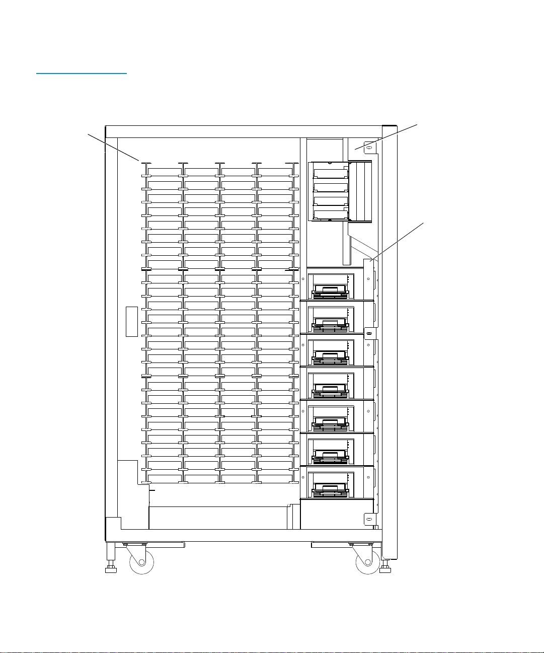
Figure 2 100
Cartridge Model
Fixed Storage Array
(FSA) bins
Bin 0
Bin 1
Bin 2
Bin 3
Bin 4
Bin 5
Bin 6
Bin 7
Bin 8
Bin 9
Bin 10
Bin 11
Bin 12
Bin 13
Bin 14
Bin 15
Bin 16
Bin 17
Bin 18
Bin 19
Bin 20
Bin 21
Bin 22
Bin 23
Bin 24
Bin 25
Bin 26
Bin 27
Bin 28
Bin 29
Bin 30
Bin 31
Bin 32
Bin 33
Bin 34
Bin 35
Bin 36
Bin 37
Bin 38
Bin 39
Bin 40
Bin 41
Bin 42
Bin 43
Bin 44
Bin 45
Bin 46
Bin 47
Bin 48
Bin 49
Bin 50
Bin 51
Bin 52
Bin 53
Bin 54
Bin 55
Bin 56
Bin 57
Bin 58
Bin 59
Bin 60
Bin 61
Bin 62
Bin 63
Bin 64
Bin 65
Bin 66
Bin 67
Bin 68
Bin 69
Bin 70
Bin 71
Bin 72
Bin 73
Bin 74
Bin 75
Bin 76
Bin 77
Bin 78
Bin 79
Bin 80
Bin 81
Bin 82
Bin 83
Bin 84
Bin 85
Bin 86
Bin 87
Bin 88
Bin 89
Bin 90
Bin 91
Bin 92
Bin 93
Bin 94
Bin 95
Bin 0
Bin 1
Bin 2
Bin 3
Drive 0
Drive 1
Drive 2
Drive 3
Drive 4
Drive 5
Drive 6
Load port bins
Tape dr iv e s
4 Quantum|ATL 7100 Series Library Operator’s Guide
Page 21
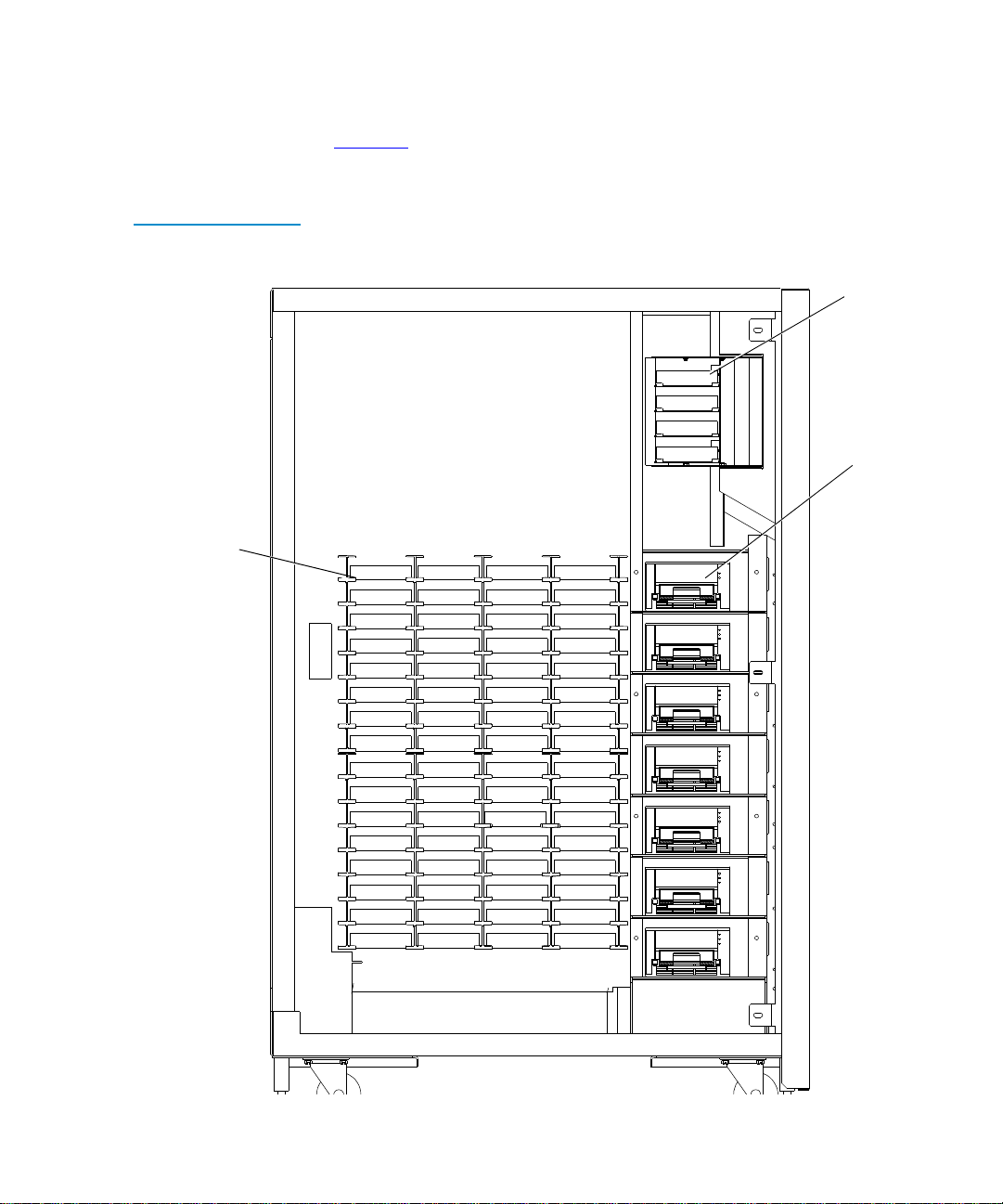
Figure 3 68 Cartridge
Model
FSA bins
Chapter 1 Introduction
Overview
Figure 3 shows the numbering convention for the “68 cartridge
model”.
Load port bins
Bin 0
Bin 1
Bin 2
Bin 3
Tape dr ives
Bin 0
Bin 1
Bin 2
Bin 3
Bin 4
Bin 5
Bin 6
Bin 7
Bin 8
Bin 9
Bin 10
Bin 11
Bin 12
Bin 13
Bin 14
Bin 15
Bin 16
Bin 17
Bin 18
Bin 19
Bin 20
Bin 21
Bin 22
Bin 23
Bin 24
Bin 25
Bin 26
Bin 27
Bin 28
Bin 29
Bin 30
Bin 31
Bin 32
Bin 33
Bin 34
Bin 35
Bin 36
Bin 37
Bin 38
Bin 39
Bin 40
Bin 41
Bin 42
Bin 43
Bin 44
Bin 45
Bin 46
Bin 47
Bin 48
Bin 49
Bin 50
Bin 51
Bin 52
Bin 53
Bin 54
Bin 55
Bin 56
Bin 57
Bin 58
Bin 59
Bin 60
Bin 61
Bin 62
Bin 63
Drive 0
Drive 1
Drive 2
Drive 3
Drive 4
Drive 5
Drive 6
Quantum|ATL 7100 Series Library Operator’s Guide 5
Page 22
Chapter 1 Introduction
Operator Accessible Components
Operator Accessible Components 1
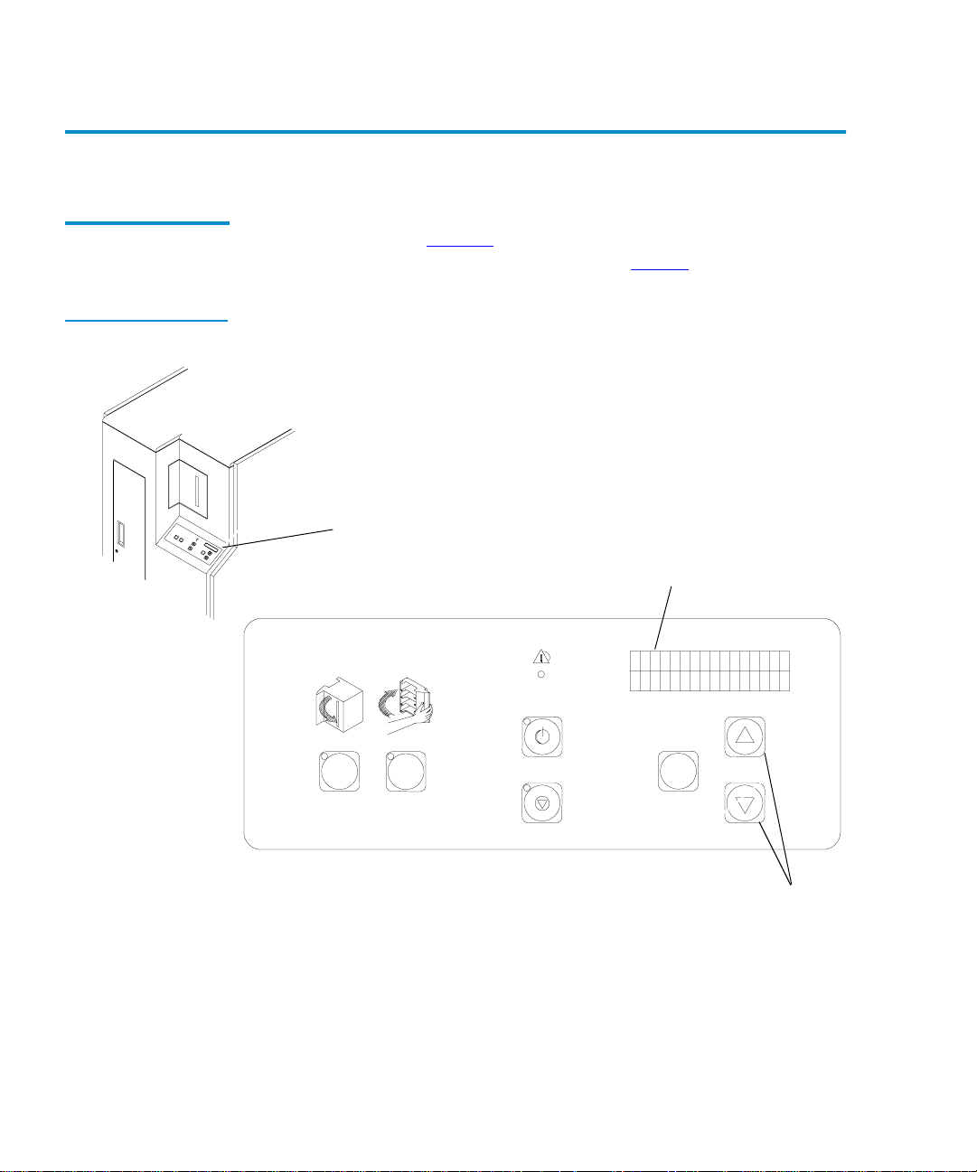
Control Panel 1
Figure 4 Control
Panel
The control panel (figure 4
) is located on the right side at the front
of the library. Its features are described in table 1
Control panel
Status display area
(16 characters/2 lines)
FAULT
.
STANDBY
OPEN CLOSE
STOP
6 Quantum|ATL 7100 Series Library Operator’s Guide
SELECT
Scrolling buttons
(Up {↑} and down {↓})
Page 23

Table 1 Controls on
the Control Panel
Control Library Function
Chapter 1 Introduction
Operator Accessible Components
OPEN
(load port)
OPEN button opens the load port door providing access to the four
The
loading bins. When pressed, the following occurs:
1. Park the robotics (green indicator blinks).
2. Unlock and open the load port door (green indicator illuminated).
3. Lock the load port door in the open position (green indicator off).
CLOSE
(load port)
CLOSE button closes the load port door. When pressed, the
The
following occurs:
1. Park the robotics (red indicator blinks) .
2. Unlock the door (red indicator illuminated).
3. The operator closes the door (red indicator illuminated).
4. The library locks the door in the closed position (red indicator off).
STANDBY The STANDBY button toggles the library between online mode and
standby mode.
On-line mode —normal operation, the red indicator is Off.
Standby mode — host communications are disabled, the control panel
menu mode is available, the diagnostic port on the rear panel (
DIAG) is
active, and the red indicator is On. If chosen during a transfer operation,
the library completes the operation before sta ndby mode is active (the
red indicator blinks during the completion of the transfer).
STOP
SELECT
↑↓
The STOP button removes power to the robotic equipment (red indicator
illuminates). Pressing the button again restores power to the robitics (red
indicator off).
With the library in STANDBY mode, pressing the
SELECT button
activates the menu mode. In menu mode, a menu appears in the bottom
line of the status display area (SDA). An operator then uses the
↑ and ↓
buttons to scroll menu options in the SDA. When the desired menu
option is displayed, the operator then chooses the SELECT button.
For detailed procedures on using the menu mode, see Chapter 3,
Operator Troubleshooting
Quantum|ATL 7100 Series Library Operator’s Guide 7
.
Page 24

Chapter 1 Introduction
Operator Accessible Components
Control Library Function
FAULT
(Indicator)
Status Display
Area
Load Port 1
The FAULT indicator illuminates when the library has an error condition.
The SDA displays the name of the error condition. For a listing and
detailed description of all status messages shown in the SDA, see chapter
3, Operator Troubleshooting
This is a 16-character, 2-line liquid crystal display (LCD) display. It
displays status messages that describe the operating state of the library. It
also displays menu options when the library is in menu mode.
.
The load port is located at the front of the library above and to the
left of the control panel (see figure 1
and/or remove up to four tape cartridges (see table 1
). It allows an operator to insert
for a
description of the lo ad port buttons).
To load/remove cartridges, press the OPEN button. When the
indicator stops blinking, the load port door opens and allowing the
operator to insert tape cartridges. To close , press the
CLOSE button
and push the door to the closed position.
Caution:
You must release the CLOSE button before pushing
the load port door closed.
For the unload operation, the gripper places tape cartridges in the
load port bins. Looking through the view port, the operator will be
able to decide if an unload operation is necessary. Pressing the
OPEN button automatically opens the door allowing the operator
to remove the tape cartridge(s).
8 Quantum|ATL 7100 Series Library Operator’s Guide
Page 25

Figure 5 Load Port
Chapter 1 Introduction
Operator Accessible Components
Load port (closed)
(View port)
Load port (open)
Cartridge
(Closes to left)
Quantum|ATL 7100 Series Library Operator’s Guide 9
Page 26

Chapter 1 Introduction
Operator Accessible Components
Front Door 1
Figure 6 Front Door
The front door accesses the library interior for manually loading/
unloading tape cartridges (typically done by field service
engineers during maintenance procedures). For safety purposes,
an interlock switch removes power from the robotics equipment
when the door is opened.
Always press the STANDBY button to open any library door. Do
not open until the
System Off-line is then displayed on the SDA.
STANDBY indicator blinks , then becom es solid.
Front door (open)
Handle
Interlock
switch
(open to right)
10 Quantum|ATL 7100 Series Library Operator’s Guide
Page 27

Chapter 1 Introduction
Operator Accessible Components
Storage Array Door
Figure 7 Storage
Array Door
The storage array door is used for bulk loading and unloading of
1
cartridges (see figure 7
). For safety purposes, an interlock switch
removes power from the robotics equipment when the door is
opened.
Always press the STANDBY button to open any library door. The
FAULT indicator flashes until the current command is completed.
Wait until the
STANDBY indicator is on solid and System Off-line is
displayed before opening the door.
Storage array door
Quantum|ATL 7100 Series Library Operator’s Guide 11
Page 28

Chapter 1 Introduction
Operator Accessible Components
Drive Access Door
Figure 8 Drive Access
Door
The drive access door (see figure 8
1
service engineers and is not normally used by operators . For safety
) is intended for use by field
purposes, an interlock switch removes power from the robotics
equipment when the door is opened.
Always press the STANDBY button to open any library door. The
FAULT indicator flashes until the current command is completed.
Wait until the
STANDBY indicator is on solid and System Off-line is
displayed before opening the door.
Drive access door
12 Quantum|ATL 7100 Series Library Operator’s Guide
Page 29

Chapter 1 Introduction
Operator Accessible Components
Rear Panel 1
Figure 9 Rear Panel
The rear panel of the library contains the AC power switch, AC
power receptacle and the communication ports for the host, tape
drives and diagnostic PC (see figure 9
). The operator’s only
responsibility concerning the rear panel is to verify the cables are
properly connected and to turn library power on or off with the
AC power switch.
DIAG (RS-232 diagnostic port)
SCSI ports
(port 8 at top,
port 1 at bottom)
AC power receptacle
and power switch
Quantum|ATL 7100 Series Library Operator’s Guide 13
Page 30

Chapter 1 Introduction
Operator Accessible Components
14 Quantum|ATL 7100 Series Library Operator’s Guide
Page 31

Chapter 2
2Operating the Library
This chapter describes the following basic library features:
• Operating procedures
• Adding or removing tape cartridges
• Using the control panel
Operating Procedures 2
Applying Power to the Library
To apply power to the library:
2
1 Verify the foll owing:
• Front door and load port are closed
• All outer panels are attached
• All back panel connections are secured
2 At the back panel, set the AC power switch to the I (on)
position.
Quantum|ATL 7100 Series Library Operator’s Guide 15
Page 32

Chapter 2 Operating the Library
Operating Procedures
3 After several seconds, verify that SDA shows System On-line.
Note: System On-line is only displayed if the library power-
up state is configured for
Off-line
is displayed.
On-line. Otherwise, System
Placing the Library Online
Taking the Library Offline
Removing Power from the Library
To place the library online:
2
1 With the library power applied and the SDA showing System
Off-line
2 Verify that System On-line is displayed in the SDA.
, press the control panel STANDBY button.
To take the library offline:
2
1 With the library power applied and the SDA showing System
On-line, press the control panel
2 The library robotics will stop after completing the current
STANDBY button.
command(s). Verify that System Off-line is displayed in the
SDA.
To remove power from the library:
2
1 Press the control panel STANDBY button. The library robotics
will stop after completing the current command(s). Verify that
System Off-line is displayed in the SDA.
2 At the rear panel, set the AC power switch to the O (off)
position.
Caution: Always leave library power off for at least 15
seconds before turning the power on again.
16 Quantum|ATL 7100 Series Library Operator’s Guide
Page 33

Chapter 2 Operating the Library
Operating Procedures
Worki ng With Tape Cartridges
Figure 10 Bar Code
Label on a Tape
Cartridge
Applying Bar Code Labels to Cartridges 2
2
A bar code label is the identification for the cartridge. Apply a bar
code label to all cartridges used in the library. When applying:
• Only use the bar code labels provided with the library.
• Apply the bar code label to the front face (see figure 10
Bar code label
Adding Tape Cartridges Through the Load Port 2
Note: Enable the auto load option before performing this task
(see Enabling/Disabling the Auto Load Option
page 36).
).
on
Caution: DO NOT USE CompacTape I, CompacTape IIor
CompacTape IIIXT tape cartridges in this library.
Caution: Examine all cartridges before adding them to the
library. Look for label stock or f oreign mate rial that
may be clinging to the cartridges.
To add a tape cartridge through the load port:
1 Verify that each cartridge has a bar code label.
Quantum|ATL 7100 Series Library Operator’s Guide 17
Page 34

Chapter 2 Operating the Library
Operating Procedures
2 Press the load port OPEN button and verify the indicator
3 With the load port door open, place the ta pe cartridge( s) in any
4 Press the load port CLOSE button.
begins blinking. (It may take several seconds for the load port
door to automatically open.)
Caution: Mechanical hazards could be exposed when the
load port is partially open or closed. Do not
attempt to insert hands or fingers into the load
port opening at any time.
available bin (see figure 11
Caution: The load port door is locked in the open position.
You must press the
).
CLOSE button before
attempting to close the load port door.
Figure 11 Inserting
and Removing Tapes
5 When the CLOSE indicator is steadily lit, push the load port
door closed. (The library will lock the door.)
Tape cartridge
Bar code label
opens to right/
closes to left
Load port
18 Quantum|ATL 7100 Series Library Operator’s Guide
Page 35

Chapter 2 Operating the Library
Operating Procedures
Removing Tape Cartridges from the Load Port 2
To remove a tape cartridge from the load port:
Note: Use the view port to determine if the load port contains
tape cartridges to be removed.
1 When tape cartridges are ready to be removed, press the load
port
OPEN button and verify the indicator is blinking. (It may
be several seconds before the load port door automatically
opens.)
Warning: Mechanical hazards could be exposed when the
load port is partially open or closed. Do not
attempt to insert hands or fingers into the load
port opening at any time.
2 Remove the tape cartridge(s) from the load port bin(s).
3 Press the load port CLOSE button.
Caution: The load port door is locked in the open position.
You must press the
CLOSE button before
attempting to close the load port door.
4 When the CLOSE indicator is steadily lit, push the load port
door closed. The library locks the door.
Bulk Loading or Unloading of Cartridges 2
It is recommended to add or remove tape cartridges from the
library using the load port. However, there may be situations (such
as initial loading of the l ibr ary) whe n you n eed to load or unload a
Quantum|ATL 7100 Series Library Operator’s Guide 19
Page 36

Chapter 2 Operating the Library
Operating Procedures
large number of cartridges. In this situation, you can load or
unload the cartridges through the storage array door.
Caution: DO NOT USE CompacTape I, CompacTape IIor
To bulk load or unload cartridges through the storage array door:
1 If loading cartridges, verify all cartridges have a bar code label.
2 If the library is powered on, press the control panel STANDBY
3 Open the storage array door.
CompacTape IIIXT tape cartridges in this library.
Note: Use the bar code labels provided with the library.
button. The library robotics will stop after completing the
current command(s). Verify that System Off-line is displayed
in the SDA.
4 Unload and/or load tape cartridges in the bins. When loading
a cartridge, insert the cartridge in the proper orientation (see
figure 10
, bar code label facing out and on the left side).
20 Quantum|ATL 7100 Series Library Operator’s Guide
Page 37

Figure 12 Tape
Cartridge Orientation
Chapter 2 Operating the Library
Operating Procedures
Quantum|ATL 7100 Series Library Operator’s Guide 21
Page 38

Chapter 2 Operating the Library
Operating Procedures
5 When finished, close the storage array door.
6 Press the control panel STANDBY button, and verify that
Note: The load port bins are keyed to ensure that tape
cartridges are inserted in the proper orientation.
Fixed storage array bins inside the library, however,
are not keyed, and you MUST ensure that cartridges
are loaded in the proper orientation.
System On-line is displayed in the SDA.
Turning the Interior Light On or Off
The library is normally shipped with the interior light set to the On
position. Use the following procedure to turn the interior light on
2
or off.
Note: The interior light bulb is not an operator-replaceable
item. If the light bulb needs replacement, notify your
field service engineer.
1 Press the control panel STANDBY button. The library robotics
will stop after completing the current command(s). Verify that
System Off-line is displayed in the SDA.
2 Open the front door by pulling the door towards you. (The
door opens to your right.)
3 Reach through the front door and set the light switch on the far
side of the light to the desired position (see figure 13
4 Close and latch the library front door.
5 Press the control panel STANDBY button, and verify that
System On-line is displayed in the SDA.
).
22 Quantum|ATL 7100 Series Library Operator’s Guide
Page 39

Figure 13 T ur nin g th e
Interior Light On/Off
Power
switch
Chapter 2 Operating the Library
Using the Control Panel Menus
Interior light
(opens to right)
Using the Control Panel Menus 2
Entering Menu Mode
To enter menu mode:
2
1 Press the control panel STANDBY button, and verify the SDA
displays System Off-line.
2 Press the SELECT button to enter menu mode. Verify the
following is displayed in the SDA:
Quantum|ATL 7100 Series Library Operator’s Guide 23
Page 40

Chapter 2 Operating the Library
Using the Control Panel Menus
Menu:
Configuration
Menu Navigation 2
In menu mode, the Status Display Area (SDA) displays two lines:
Line 1
Line 2
The upper line (line 1) of the display is passive. It shows the name
of the current menu or submenu.
The lower line (line 2) is the active line and shows the items that
can be selected from the current menu. Each item on the menu is
either a submenu or a function.
When you press the “up arrow” (↑) and “down arrow” (↓) buttons,
line 2 scrolls through the options available for the current menu.
When you press the
SELECT button, the submenu or function
displayed on line 2 is selected or executed.
There is an Exit option at the end of each menu, submenu and
option list. When you select
Exit, you are returned to the previous
menu.
The overall structure the menus is shown in figure 14.
Figure 15 is an example of menu navigation. It shows the
commands and associated SDA displays involved in changing the
“Auto Clean” option from “Disabled” (factory default) to
“Enabled.”
Exiting Menu Mode 2
There are two ways to exit from menu mode:
• Conventional method
• Fast method
24 Quantum|ATL 7100 Series Library Operator’s Guide
Page 41

Figure 14 Menu
Structure
Chapter 2 Operating the Library
Using the Control Panel Menus
Main Menu
Configuration
Inquiry
SCSI Address
Power-Up State
Num of Drives
Auto Clean
Retries
Auto Load
Language
Set View
Auto Inventory
No Barcode Scan
Emulate Exabyte
4/52 Identity
Temperature Det
Exit Menu
Drive Control
Unload
Clean
Exit Menu
Calibration
Cal All
Cal Storage
Cal Drives
Cal Load Port
Exit Menu
System Test Robot Control Diagnostics
Random Shuffle
Random /No Scan
Pick Each Bin
Pick All
Report Results
Exit Menu
Empty Load Port
Pick Bin
Pick Drive
Place Bin
Place Drive
Barcode Bin
Barcode Drive
Exit Menu
Home All
Selftest All
Status Actuator
Move Actuator
Inventory
Exercise All
Exit Menu
Quantum|ATL 7100 Series Library Operator’s Guide 25
Page 42

Chapter 2 Operating the Library
Using the Control Panel Menus
Figure 15 Menu
Navigation Example
Main menu function
“Configuration”
Submenu function
“Auto Clean”
“<” (less than sign)
indicates feature is
active
Status Display
Menu:
Configuration
Menu: Configurati
Inquiry
SCSI Address..
Power-Up State
Num of Drives..
Menu: Configurati
Auto Clean..
Menu: Auto Cle an
Enabled
Menu: Enabled
..Working..
SUCCESS
Menu: Auto Cle an
Enabled<
Switch
SELECT — Select the “Configuration” menu
Ø — Bypass the “Inquiry” submenu
Ø — Bypass the “SCSI Address” submenu
Ø — Bypass the “Power-Up State” submenu
Ø — Bypass the “Num of Drives” submenu
SELECT — Choose the “Auto Clean” submenu
SELECT — Select the “Enabled” Option
— The SDA displays the status
“SUCCESS” when the function is
finished.
— Press the
SELECT button simultaneously to exit
the menu mode or use them separately
to navigate to the Exi t or a nother
function.
Description
↑ or↓ button and the
Exiting from Menu Mode: Conventional Method 2
Use the ↑ and ↓ buttons to navigate to an Exit option, then press
the
SELECT button. This takes you one level up in the menu
hierarchy.
1 Continue until the f ollowing is displayed in the SDA.
Menu:
Exit
2 Press SELECT to exit menu mode.
26 Quantum|ATL 7100 Series Library Operator’s Guide
Page 43

Chapter 2 Operating the Library
Using the Control Panel Menus
Exiting from menu mode: fast method 2
1 If the results of an operation are displayed in the SDA, press
the
↑ or ↓ button to clear the SDA.
Note: If the results of an operation are displayed in the
SDA, the quick method of exiting menu mode is not
available until the results are cleared.
2 From anywhere in the menus, press the SELECT button and the
↑ or ↓ button simultaneously.
Performing Library Diagnostics
The Diagnostics menu has options available to:
2
• Home all actuators in the library (Home All)
• Command the library to perform a self-test (Selftest All)
• Display the library actuator status (Status Actuators)
• Display the library sensor status (Status Sensor)
• Command a robotic actuator to move (Move Actuator)
• Perform a library inventory (Inventory)
• Exercise the library robotic actuators (Exercise All)
This section only describes how to use the Diagnostics menu
option for performing a self-test to verify proper configuration and
operation of the library. For a description of other Diagnostic menu
options, refer to the Quantum|ATL 7100 Series Field Service Manual.
Note: As an alternate method of testing the library, you can use
the Diagnostic Software Package (DSP). Refer to the
Quantum|ATL 7100 Series Library Diagnostic Soft ware
User’s Manual for more information about the DSP.
Quantum|ATL 7100 Series Library Operator’s Guide 27
Page 44

Chapter 2 Operating the Library
Using the Control Panel Menus
Performing a Library Self-Test 2
This option performs a complete self-test of the library.
1 Press and release the control panel STANDBY button, and
2 To enter menu mode, press and release the SELECT button.
3 Press the ↓ button until Diagnostics is displayed in the SDA:
4 Press the SELECT button to select the Diagnostics menu. Verify
verify the SDA shows Off-line.
Verify the following is displayed in the SDA:
Menu:
Configuration..
Menu:
Diagnostics..
the following is displayed in the SDA:
Menu:Diagnostics
Home All
5 Press the ↓ button until Selfte st All is displayed in the SDA:
Menu:Diagnostics
Selftest All
6 Press the SELECT button. The following is displayed in the
SDA:
Menu:Selftest Al
..WORKING..
7 The self-test should take several seconds to complete. If the
self-test completes successfully, the following is displayed in
the SDA:
Menu:Selftest Al
SUCCESS
28 Quantum|ATL 7100 Series Library Operator’s Guide
Page 45

Chapter 2 Operating the Library
Using the Control Panel Menus
Setting the Library SCSI Address
The SCSI address of the library can be set using the SCSI Address/
2
Robotics submenus.
Note: The default SCSI address for the library is 0 (zero).
Note: SCSI address 7 is typically reserved for the host
controller.
1 Enter the menu mode.
2 Press the SELECT button to choose the Configuration menu
and verify the following is displayed in the SDA:
Menu:Configuration
Inquiry
3 Press the ↓ button once time to bypass the Inquiry menu and
verify the following is displayed in the SDA:
Menu:Configuration
SCSI Address
4 Press the SELECT button to choose the SCSI Address submenu
and verify the following is displayed in the SDA:
Menu:SCSI Address
Robotics
5 Press the SELECT button to choose the Robotics submenu and
verify the following is displayed in the SDA:
Menu:Robotics
SCSI ID 0
6 Use the ↑ and ↓ buttons to navigate to the SCSI ID number for
the library.
7 With the proper SCSI ID number displ ayed on line 2, press the
SELECT button.
Quantum|ATL 7100 Series Library Operator’s Guide 29
Page 46

Chapter 2 Operating the Library
Using the Control Panel Menus
8 Exit the menu mode.
Note: After changing the SCSI address of the library, one of
two things must happen to set the new SCSI ID: the
host controller must issue a “SCSI Bus Reset,” or the
library must be powered off and on again.
Setting a Tape Drive SCSI Address
Table 2 Default Tape
Drive SCSI Address
The SCSI Address/ Drive function is used to set the SCSI address
of tape drives in the library. The library ships with the tape drives
2
configured as shown in table 2
SCSI Address Drive Number Physical Location
10 top drive
21 second drive
3 2 third drive
43 fourth drive
5 4 fifth drive
65 sixth drive
1 (second bus) 6 bottom drive
Note:
SCSI address 7 is typically reserved for the host
.
controller.
To change the SCSI addresses of the drives in the library:
1 Enter the menu mode.
30 Quantum|ATL 7100 Series Library Operator’s Guide
Page 47

Chapter 2 Operating the Library
Using the Control Panel Menus
2 Press the SELECT button to c hoose the C onfigurat ion menu
and verify the following is displayed in the SDA:
Menu:Configuration
Inquiry
3 Use the ↓ button to bypass the Inquiry menu and verify the
following is displayed in the SDA:
Menu:Configuration
SCSI Address
4 Press the SELECT button again to choose SCSI Address and
verify the following is displayed in the SDA:
Menu:SCSI Addres
Robotics
5 Use the ↓ button to bypass the Robotics submenu and verify
the following is displayed in the SDA:
Menu:SCSI Addres
Drive 0
6 Use the ↑ and ↓ buttons to select the proper drive number to
set or change (see table 3
Quantum|ATL 7100 Series Library Operator’s Guide 31
).
Page 48

Chapter 2 Operating the Library
Using the Control Panel Menus
Table 3 Tape Drive
Locations
Tape Drive Number Physical Location
Drive 0 top drive
Drive 1 second drive
Drive 2 third drive
Drive 3 fourth drive
Drive 4 fifth drive
Drive 5 sixth drive
Drive 6 bottom drive
7 With the proper drive number displayed on line 2, press the
SELECT button and verify the following is displayed in the
SDA:
Menu:Drive 0
SCSI ID 0
8 Use the ↑ and ↓ buttons to navigate to the SCSI ID for the
selected drive.
9 With the proper SCSI ID displayed on line 2, press SELECT.
10 Exit the menu mode.
11 After changing the SCSI address of the drives, do one of the
following to set the new SCSI ID:
• Run the Reset Drives command from the Diagnostic
Software Package.
• Issue a “SCSI Bus Reset” from the host controller.
• Power the library off and on again.
Caution:
If you turn the library power off and then on
again, be sure to leave the power off for at least
15 seconds before turning power back on.
32 Quantum|ATL 7100 Series Library Operator’s Guide
Page 49

Chapter 2 Operating the Library
Using the Control Panel Menus
Defining the Library Power-Up State
The condition of the library after power-up, self-tests and
initialization can be def ined as eith er On-l ine or standby (Off- line).
2
The default is On-line.
To change the power-up state:
1 Enter the menu mode.
2 Press the SELECT button to choose the Configuration menu
and verify the following is displayed in the SDA:
Menu:Configuration
Inquiry
3 Use the ↓ button to bypass the Inquiry menu and verify the
following is displayed in the SDA:
Menu:Configuration
Power-Up State
4 Press the SELECT button to choose the Power-Up State menu
and verify the following is displayed in the SDA:
Menu:Power-Up State
On-line<
Note:
System On-line is the default. If you want to change
the power-up state to standby, proceed to step 5.
Otherwise, exit the menu mode.
5 Use the ↓ button to bypass the System On-line option and
verify the following is displayed in the SDA:
Menu:Power-Up State
Standby<
6 With the desired option displayed on line 2, press the SELECT
button.
7 Exit the menu mode.
Quantum|ATL 7100 Series Library Operator’s Guide 33
Page 50

Chapter 2 Operating the Library
Using the Control Panel Menus
Enabling/Disabling the Auto Clean Option
2
The automatic drive cleaning feature has two modes of drive
cleaning support:
• Auto clean enabled
• Auto clean disabled
In disabled mode, drive cleaning is enabled by the System
Administrator at the host computer. Although the library unit will
internally track cleaning tape cartridge movement and use, the
library unit provides no cleaning support in this mode. The host is
responsible for all cleaning functions, such as detecting when a
drive requires cleaning, tracking and selecting cleaning tape
cartridges, initiating media movement of the cleaning tape
cartridge to the drive and determining when a cleaning tape
cartridge has been “used up.”
With auto clean enabled, the library monitors each drive’s status to
determine when a drive requires cleaning and initiates action
when that determination is made. The library selects an available
cleaning tape cartridge, handles media movement of the cleaning
tape cartridge to and from the drive and supervises the cleaning
operation in the drive. The library tracks cleaning tape cartridges
within the library, monitors cleaning tape cartridge use and
determines when a cleaning tape cartridge has been “used up.” A
“used up” cleaning tape cartridge is exported to the load port
under control of the library.
The library is shipped with automatic drive cleaning disabled.
To enable or disable the auto clean option:
1 Enter the menu mode.
2 Press the SELECT button to choose the Configuration menu
and verify the following is displayed in the SDA:
Menu:Configuration
Inquiry
34 Quantum|ATL 7100 Series Library Operator’s Guide
Page 51

Chapter 2 Operating the Library
Using the Control Panel Menus
3 Use the ↓ button to bypass the Inquiry, SCSI Address, and
Power-Up State menus and verify the following i s displa yed in
the SDA:
Menu:Configuration
Auto Clean
4 With Auto Clean displayed on line 2 of the SDA, press the
SELECT button and verify the following is displayed in the
SDA:
Menu:Auto Clean
Enabled
5 With the desired option displayed on line 2, press the SELECT
button.
6 Exit the menu mode.
Enabling/Disabling the Retries Option
2
When the retries option is enabled, the library attempts to recover
from internal anomalies to complete a host command.
1 Enter the menu mode.
2 Press the SELECT button to choose the Configuration menu.
3 Verify the following is displayed in the SDA:
Menu:Configuration
Inquiry
4 Use the ↓ button to bypass the Inquiry, SCSI Address, Power-
Up State and Auto Clean menus and verify the following is
displayed in the SDA:
Menu:Configuration
Retries
Quantum|ATL 7100 Series Library Operator’s Guide 35
Page 52

Chapter 2 Operating the Library
Using the Control Panel Menus
5 With Retries displayed on line 2 of the SDA, press the SELECT
button and verify the following is displayed in the SDA:
Menu:Retries
Enabled
Enabling/Disabling the Auto Load Option
2
Note:
Retries Ena bled is the default. If you want to disable
this feature, proceed to step 6. Otherwise, exit the
menu mode.
6 Use the ↓ button to bypass the Enabled option and verify the
following is displayed in the SDA:
Menu:Retries
Disabled
7 With the desired option displayed on line 2, press the SELECT
button.
8 Exit the menu mode.
The auto load option allows the operator to l oad cartridges into the
fixed storage array without any intervention from the host
controller. When this option is enabled, the library automatically
finds bins in the FSA for cartridges that are placed in the load port.
If no bin locations are available in the FSA, the cartridges are left in
the load port bin and an error message is displayed on the control
panel SDA.
The default for the auto load option is disabled.
To change the auto load setting:
1 Enter the menu mode.
2 Press the SELECT button to choose the Configuration menu.
3 Verify the following is displayed in the SDA:
Menu:Configurati
Inquiry
36 Quantum|ATL 7100 Series Library Operator’s Guide
Page 53

Chapter 2 Operating the Library
Using the Control Panel Menus
4 Use the ↓ button to bypass the Inquiry, SCSI Address, Power-
Up State, Number of Drives, Auto Clean, and Retries menus
and verify the following is displayed in the SDA:
Menu:Configurati
Auto Load
5 With Auto Load displayed on line 2 of the SDA, press the
SELECT button and verify the following is displayed in the
SDA:
Menu:Auto Load
Disabled
Setting the Status Display Area Language
Note:
Auto Load Disabled is the default. If you want to
enable this feature,
proceed to step 6. Otherwise, exit
the menu mode.
6 Use the ↓ button to bypass the Enabled option and verify the
following is displayed in the SDA:
Menu:Auto Load
Enabled
7 With the desired option displayed on line 2, press the SELECT
button.
8 Exit the menu mode.
The language of text displayed in the status dis play area (SDA) c an
be set to a ny of the following:
2
• English (default)
• Francais
• Deutsch
• Espanol
• Italiano
Quantum|ATL 7100 Series Library Operator’s Guide 37
Page 54

Chapter 2 Operating the Library
Using the Control Panel Menus
To change the SDA language:
1 Enter the menu mode.
2 Press the SELECT button to choose the Configuration menu.
3 Verify the following is displayed in the SDA:
4 Use the ↓ button to bypass the Inquiry, SCSI Address, Power-
5 With Language displayed on line 2 of the SDA, press the
Menu:Configurati
Inquiry
Up State, Auto Clean, Retries and Auto Load sub-menus and
verify the following is displayed in the SDA:
Menu:Configurati
Language
SELECT button and verify the following is displayed in the
SDA:
Menu:Language
English
6 Use the ↑ and ↓ buttons to navigate to the desired language.
7 With the desired language displayed on line 2, press the
SELECT button.
8 Exit the menu mode.
Adjusting the Status Display Area Contrast
38 Quantum|ATL 7100 Series Library Operator’s Guide
To adjust the status display area contrast:
1 Enter the menu mode.
2
2 Press the SELECT button to choose the Configuration menu.
3 Verify the following is displayed in the SDA:
Menu:Configurati
Inquiry
Page 55

Chapter 2 Operating the Library
Using the Control Panel Menus
4 Use the ↓ button to bypass the Inquiry, SCSI Address, Power-
Up State, Auto Clean, Retries, Auto Load, and Language sub
menus and verify the following is displayed in the SDA:
Menu:Configurati
Set View
5 With Set View displayed on line 2 of the SDA, press the
SELECT button and verify the following is displayed in the
SDA:
Menu:Set View
Contrast 9
6 Use the ↑ and ↓ buttons to navigate to the desired contrast.
7 With the desired contrast displayed on line 2, press the
SELECT button.
8 Exit the menu mode.
Quantum|ATL 7100 Series Library Operator’s Guide 39
Page 56

Chapter 2 Operating the Library
Using the Control Panel Menus
Cleaning a Drive 2
You can use the drive clean option to clean a drive when
autocleaning is disabled or additional cleaning is required for a
drive (see Enabling/Disabling the Auto Clean Option
on page 34
for a description of the auto clean option.
1 Enter the menu mode.
2 Use the ↓ button to bypass the Configuration menu and verify
the following is displayed in the SDA:
Menu:
Drive Control
3 Press the SELECT button to choose the Drive Control menu.
4 Verify the following is displayed in the SDA:
Menu:Dr i v e C o nt r
Unload
5 Use the ↓ button to bypass the Unload submenu. Verify the
following is displayed in the SDA:
Menu:Dr i v e C o nt r
Clean
6 Press the SELECT button to choose the Clean sub-menu and
verify the following is displayed in the SDA:
Menu:Clean
Drive 1
7 Use the ↑ and ↓ buttons to select the proper drive number (see
table 3
8 With the proper drive number displayed on line 2, press the
).
SELECT button and verify the following is displayed:
Menu:Drive n
..Working..
Where n = the number of the drive that you selected.
40 Quantum|ATL 7100 Series Library Operator’s Guide
Page 57

Chapter 2 Operating the Library
Using the Control Panel Menus
9 When the following is displayed in the SDA, exit the menu
mode.
Menu:Clean
Drive n
Table 4 Tape Drive
Locations
Displaying the Library’s Ac tuator Status
Tape Drive Number Physical Location
Drive 0 top drive
Drive 1 second drive
Drive 2 third drive
Drive 3 fourth drive
Drive 4 fifth drive
Drive 5 sixth drive
Drive 6 bottom drive
This option reports the position of each of the four actuators
(horizontal, vertical, extension, gripper) in the library. You can use
2
this option to test for proper operation and tracking of each
actuator.
1 Enter the menu mode.
2 Use the ↓ button to bypass the Configuration, Drive Control,
Calibration, System Test, and Robot Control menus and verify
the following is displayed in the SDA:
Menu:
Diagnostics
Quantum|ATL 7100 Series Library Operator’s Guide 41
Page 58

Chapter 2 Operating the Library
Using the Control Panel Menus
3 Press the SELECT button to choose the Diagnostics menu and
4 Press the ↓ button twice to bypass the Home All and Selftest
5 Use the ↑ and ↓ buttons to scroll to the function that you want
verify the following is displayed in the SDA:
Menu:Diagnostics
Home All
All submenus. Then verify the following is displayed in the
SDA:
Menu:Diagnostics
Status Actuator
to display (Status Actuator or Status Sensor).
Note:
6 With the selection displayed on line 2, press the SELECT
Status Sensor is not currently supported.
button.
7 Use the ↑ and ↓ buttons to scroll through the (SDA line 2)
displays to review the information returned.
The following is an example for a status actuator:
Menu:Status Actu
1.51 11.8 3.25 C
1.51 = horizontal position
11.8 = vertical position
3.25 = extension position
c = gripper state-closed/open/unknown
8 When you have finished viewing the status of the library
sensors or actuators, exit the menu mode.
42 Quantum|ATL 7100 Series Library Operator’s Guide
Page 59

Chapter 2 Operating the Library
Using the Control Panel Menus
Performing an Inventory
This feature allows you to perform an inventory of the cartridges
2
contained in the library. The inventory information is written to
system RAM.
Note: Inventory information is maintai ned in system RAM and
is not retained if the system power is removed.
To perform an inventory:
1 Enter the menu mode. Verify the following is displayed in the
SDA:
Menu:
Configuration..
2 Use the ↓ button until Diagnostics is displayed in the SDA:
Menu:
Diagnostics
3 Press the SELECT button to select the Diagnostics menu. Verify
the following is displayed in the SDA:
Menu:Diagnostics
Home All
4 Press the ↓ button until the Inventory opti on on the Diagnosti c
menu is displayed:
Menu:Diagnostics
Inventory
Quantum|ATL 7100 Series Library Operator’s Guide 43
Page 60

Chapter 2 Operating the Library
Using the Control Panel Menus
5 With Inventory displayed on line 2, press the SELECT button.
6 When the SDA returns to the previous menu as shown below
7 Press and release the ↑ or ↓ button to clear the display.
8 Press and release the ↑ or ↓ button and the SELECT button
Note: With a full library, the inventory takes less than three
minutes if all cartridges are properly bar code
labeled. The actual inventory time takes longer if the
library is not completely full or if any of the
cartridges are not properly labeled. When the library
is full of unlabeled cartridges, the inventory may take
over 27 minutes.
(i.e., inventory is complete), exit the menu mode.
Menu:Inventory
Success
simultaneously, and verify that System On-line or System OffLine is displayed in the SDA.
Enabling/Disabling 4/52 Identity Mode
Some clients utilize host software specific to the Quantum|ATL
2
520 Series library. Enabling 4/52 Identity Mode allows the host to
interface with the Quantum|ATL 7100 Series library without
changing the host software.
Note:
The 4/52 Identity Mode configures to the
Quantum|ATL 7100 Series library to issue the same
inquiry string as the Quantum|ATL 520 Series library.
However, this is not a true “emulation” because the
Quantum|ATL 7100 Series library accomodates more
storage bins and tape drives than a Quantum|ATL 520
Series library. Some storage management software may
not be able to respond properly to a Quantum|ATL 7100
Series library in 4/52 Identity Mode. Check with your
software supplier for further information.
44 Quantum|ATL 7100 Series Library Operator’s Guide
Page 61

Chapter 2 Operating the Library
Using the Control Panel Menus
To configure 4/52 Identity Mode:
1 Enter the menu mode.
2 Press the SELECT button to choose the Configuration menu.
3 Verify the following is displayed in the SDA:
Menu:Configurati
Inquiry
4 Press the ↓ button until 4/52 Identity is displayed in the SDA:
Menu:Configurati
4/52 Identity..
5 Press the SELECT button to select 4/52 Identity and verify the
following is displayed in the SDA:
Menu:4/52 Identi
Enabled
6 Use the ↑ and ↓ buttons to display the desired option
(Enabled, Disabled, or Exit Menu).
7 With the desired setting displayed on line 2, press the SELECT
button.
8 Exit the menu mode.
Quantum|ATL 7100 Series Library Operator’s Guide 45
Page 62

Chapter 2 Operating the Library
Using the Control Panel Menus
46 Quantum|ATL 7100 Series Library Operator’s Guide
Page 63

Chapter 3
3Operator Troubleshooting
This chapter provides explanations of status messages displayed in
the control panel Status Display Area (SDA) as well as the
associated action necessary (if any) to rectify specific problems.
Status Messages 3
Table 5 lists of all status messages displayed in the SDA.
The status message column shows the two lines of the SDA. If
there is only one line of text in the message, it is displayed on line
1.
The description/action column provides a brief explanation of the
message and, where necessary, steps that you can take to resolve
any problem associated with the message.
Quantum|ATL 7100 Series Library Operator’s Guide 47
Page 64

Chapter 3 Operator Troubleshooting
Status Messages
Table 5 Status
Messages
Status Message Description/Action
System On-line. The library is online and ready to communicate with the host
computer.
System Off-line. The library is offline and ready to accept commands from the
diagnostic PC (
DIAG port) or enter the control panel menu mode.
Going On-line...
Please Wait
.
Going Off-line...
Please Wait
.
The library is transitioning from offline to online but must complete
a command that is (currently) executing. When finished,
On-line
The library is transitioning from online to of fl ine but must complete
a command that is currently executing. When finished,
line
is displayed in the SDA.
is displayed in the SDA.
System
System Off-
System Power-Up. This is the first message displayed in the SDA when the library
power is cycled from off to on.
Initializing...
Wait for On-line
This is the second message displayed in the SDA , af ter System
Power-Up
the library successfully completes initialization,
displayed.
, when the library power is cycled from off to on. When
System On-line is
On-line Init Fail In the event of an initialization failure (library power has been cycled
from off to on), this message is dis p layed in the SDA following the
Initializing...Wait for On-line message. (When the library
successfully completes initialization,
the SDA.)
System On-line is displayed in
System Stopped The control panel STOP button was pressed.
System DoorOpen The library front door is open.
48 Quantum|ATL 7100 Series Library Operator’s Guide
Page 65

Chapter 3 Operator Troubleshooting
Other Problems
Other Problems 3
In addition to the status messages described in table 6, there are
other problems that may occur. Some of the problems and the
steps to resolve them are listed in table 6
Note: Coordinate your troubleshooting efforts with the System
Administrator.
Note: For a problem not listed in table 6, notify your FSE.
Table 6 Other
Problems
Problem Resolution
.
A tape drive is not ejecting the
cartridges properly.
One or more cables are
disconnected from the ports
on the rear panel.
Quantum|ATL 7100 Series Library Operator’s Guide 49
Use the procedure described in the tape drive documentation
to remove the cartridge.
If the problem persists, notify your FSE.
Perform the procedure described in Removing Po wer from
the Library on page 16.
Reconnect the cables to the corresponding port on the rear
panel, figure 9
Perform the procedure described in Applying Power to the
Library on page 15.
on page 13.
Page 66

Chapter 3 Operator Troubleshooting
Other Problems
50 Quantum|ATL 7100 Series Library Operator’s Guide
Page 67

Appendix A
0Regulatory Statements
FCC Statement 0
This equipment has been tested and found to comply with the
limits for a Class A digital device, pursuant to Part 15 of the FCC
Rules. These limits are designed to provide reasonable protection
against harmful interference when the equipment is operated in a
commercial environment. This equipment generates, uses, and
can radiate radio frequency energy and, if not installed and used in
accordance with the instruction manual, may cause harmful
interference to radio communications.
Any changes or modifications made to this equipment may void
the user’s authority to operate this equipment.
Operation of this equipment in a residential area may cause
interference in which case the user at his own expense will be
required to take whatever measures may be required to correct the
interference.
Quantum|ATL 7100 Series Library Operator’s Guide 51
Page 68

Appendix A Regulatory Statements
Industry Canada (Digital Apparatus)
This device complies with Part 15 of the FCC Rules. Operation is
subject to the following conditions:
1 This device may not cause harmful interference, and
2 This device must acc ept any inte rference received, including
interference that may cause undesired operation.
Industry Canada (Digital Apparatus) 0
Referemce: Interference-Causing Equipment Standard, ICES-003
Issue 2
This Class A digital apparatus meets all requirements of the
Canadian Interference-Causing Equipment Regulations.
Cet appareil numérique de la class e A respecte toutes l es exigences
du Reglément sur le matériel brouilleur du Canada.
CISPR-22
WARNING!
This is a Class A product. In a domestic environment this product
0
may cause radio interference in which case the user may be
required to take adequate measures.
ACHTUNG! 0
Dieses ist ein Gerät der Funkstörgrenzwertklasse A. In
Wohnbereichen können bei Betrieb dieses Gerätes
Rundfunkstörungen auftreten, in welchen Fällen der Benutzer für
entsprechende Gegenmassnahmen verantwortlich ist.
ATTENTION! 0
Ceci est un produit de classe A. Dans un environment
domestique, ce produit peut causer des interférences
radioélectriques. Il appartient alors à l'utilisateur de prendre les
mesures appropriées.
52 Quantum|ATL 7100 Series Library Operator’s Guide
Page 69

Appendix A Regulatory Statements
Notice for USA and Canada Only
Notice for USA and Canada Only 0
If shipped to USA, use the UL LISTED power cord specified below
for 100-120 V operation. If shipped to Canada, use the CSA
CERTIFIED power cord specified below for 100-120V operation.
Plug Cap Parallel blade with ground pin (NEMA 5-15P
configuration)
Cord Type: SJT, three 16 AWG (1.5 mm
18 AWG (1.0 mm
Length Maximum 15 feet (4.5m)
Rating Minimum 10 A, 125 V
ATTENTION
2
) wires
2
) or
LIRE LA REMARQUE DANS LE MODE D’EMPLOI.
REMARQUE 0
CETTE REMARQUE NE CONCERNE QUE LES ÉTATS-UNIS ET
LE CANADA.
En cas d'envoi aux États-Unis, utiliser le cordon d'alimentation
CERTIFIÉ UL et convenant pour 100-120 V.
En cas d'envoi au Canada, utiliser le cordon d'alimentation
CERTIFIÉ CSA et convenant pour 100-120 V.
Fiche Broches parallèles avec une broche de mise à la terre
(configuration NEMA 5-15P)
0
Cordon Type: SJT, trifilaire 16 AWG (1.5 mm
18 AWG (1.0 mm
Longeur Maximum 15 pieds (4.5 m)
Capacité Minimum 10 A, 125 V
Quantum|ATL 7100 Series Library Operator’s Guide 53
2
)
2
) ou
Page 70

Appendix A Regulatory Statements
Laser Statement
Laser Statement 0
Class 1 Laser
Product
Laser Klasse 1 0
Appareil à Laser
de Classe 1
CAUTION: With all panels and enclosures in place, this product is
0
rated as a Class I laser product. The bar code scanner inside this
product, however, is a Class II laser. Avoid exposure to the laser
light emitted from the bar code scanner. Do not stare into the
beam.
CAUTION: Use of controls or adjustments or performance of
procedures other than those specified herein may result in
hazardous exposure.
VORSICHT: Dieses Produkt Enthdlt Einen Laser Der Kategorie II.
Laserstrahlen - Der Strichcode-scanner Gibt Laserstrahlen aus.
VERMEIDEN SIE jeden Blickkontakt und direkten kvrperlichen
Kontakt mit diesen Strahlen.
VORSICHT: Ein nicht ordnungsgemd_er (siehe hier enthaltene
Anweisungen) Einsatz bzw. Dnderungen der Betriebsleistung
kvnnen einen gesundheitsgefdhrdenden Kontakt zur Folge haben.
ATTENTION: Ce produit émet de la classe laser II. Rayonnement
0
laser - NE PAS fixer des yeux le rayon. Éviter les expositions - Le
rayonnement laser est émis à partir du lecteur optique de code
barre.
ATTENTION: L’utilisation de contrôles ou d’ajustements de
performance des procédures autres que ceux indiqués ici peut
entraîner une exposition dangereuse.
Producto Láser de
Clase 1
¡ATENCIÓN! Este producto contiene laser de clase II. Luz de la ser
0
- NO mire el rayo. Evite el contacto con la luz: la luz de laser se
emite desde el explorador de código de barras.
54 Quantum|ATL 7100 Series Library Operator’s Guide
Page 71

Appendix A Regulatory Statements
Battery Statement
¡ATENCIÓN! El uso de los controles o ajustes para realizar
procedimientos que no son especificados puede provocar una
situación peligrosa.
Luokan 1
Laserlaite
ATTENZIONE: Questo prodotto emette una luce laser di Classe II.
0
NON guardare il facsio di luce ed evitare di esporsi alla fonte del
laser. Il fascio di luce laser h emesso dal dispositivo di scansione
del codice a barre.
ATTENZIONE: L’uso di comandi o regolazioni per eseguire le
procedure che non siano quelli specificati in questa
documentazione pur causare rischi all ‘incolumit’ delle persone.
Battery S tatement 0
CAUTION 0
LET OP 0
This product contains a Lithium battery. The Dallas
Semiconductor DS12B887 on the motherboard contains a Lithium
battery. Lithium may be considered a hazardous material. Dispose
of this battery in accordance with local, state, and federal laws.
Dit product bevat een lithiumbatterij. De DS12B887-chip van
Dallas Semiconductor op het moederbord bevat een
lithiumbatterij. Lithium kan als gevaarlijk materiaal worden
beschouwd. Werp de batterij weg in overeenstemming met de
plaatselijke en landelijke milieuwetgeving.
VAROITUS 0
Tässä tuotteessa on litiumparisto. Emolevyllä oleva Dallas
Semiconductor DS12B887 sisältää litiumpariston. Litium saattaa
olla luokiteltu vaaralliseksi aineeksi. Hävitä tämä paristo
paikalli sten lakien ja määräysten mukaisesti.
Quantum|ATL 7100 Series Library Operator’s Guide 55
Page 72

Appendix A Regulatory Statements
Battery Statement
ATTENTION 0
ACHTUNG 0
Attenzione 0
PRECAUCIÓN 0
Ce produit contient une batterie au lithium. Le composant Dallas
DS12B887 de la carte mère contient une batterie au lithium. Le
lithium peut être considéré comme un produit dangereux. Rejetez
cette batterie selon les règlements locaux, régionaux ou fédéraux.
Dieses Produkt enthält eine Lithium-Batterie. Der Dallas Halbleiter
DS12B887 auf der Hauptplatine enthält eine Lithium-Batterie.
Lithium gilt als speziell zu entsorgender Sondermüll. Bei der
Entsorgung dieser Batterie müssen die entsprechenden lokalen,
länder- und bundesweiten Gesetze und Regelungen betreffend
Sammel- und Rückgabestellen beachte t werden.
Questo prodotto contiene una batteria al litio. Il modulo Dallas
Semiconductor DS12B887 contiene una bat teria al liti o sulla sche da
madre. Il litio può essere considerato un materiale pericoloso.
Utilizzare questo tipo di batterie in accordo con le normative
vigenti.
Este producto contiene una batería de litio. El modelo Dallas
Semiconductor DS12B887 de la placa base contiene una batería de
litio. El litio puede ser considerado un material peligroso. Deseche
la batería conforme a la normativa vigente de aplicación.
VARNING! 0
Denna produkt innehåller ett litiumbatteri. Dallas Semiconductor
DS12B887 på moderkortet innehåller ett litiumbatteri. Litium kan
betraktas som ett miljöfarligt ämne. När batteriet förbrukats, ska
de lagar som gäller för miljöfarligt avfall respekteras.
56 Quantum|ATL 7100 Series Library Operator’s Guide
Page 73

Glossary
A
actuators
Robotic components that move inside the library to
manipulate cartridges. These include the gripper, extension axis,
vertical and horizontal axes.
automated tape library A robotic storage and retrieval system for
tape cartridges.
B
bar code
A printed pattern of vertical bars of varying widths used
for computerized inventory control.
bar code label The identification label on tape cartridges.
bar code scanner A device that is mounted on the extension axis
that reads the cartridge bar code labels.
C
calibration
The software measurements and configuration
required for successful operation of the library.
control panel The panel on the front of the library that contains
the Status Display Area,
E
EIA/TIA-574
A serial communications cabling and protocol
as well as indicators and control buttons.
standard for 9-pin connectors, sometimes referred to as RS-232.
The diagnostic port (
DIAG), on the rear of the library, uses this
protocol.
Quantum|ATL 7100 Series Library Operator’s Guide 57
Page 74

Glossary
extension axis assembly Mounted onto the vertical axis, the
extension axis assembly consist s of the grip per assembly and the
horizontal axis on which the gripper assembly is mounted.
extension axis belt The drive belt connecting the extension
motor/gearbox to the gripper .
F
FCC Class A
Standard established by the U.S. Federal
Communications Commission governing electromagnetic
emissions in a commercial environment.
FSA Fixed Storage Array. This is a 3-column by 32-row fixture
mounted inside the library. Its purpose is to store up to 96
cartridges in the library.
FSE Field Service Engineer
G
gripper assembly
The assembly that mounts on the extension axis
and grips cartridges; referred to as the gripper.
H
horizontal belt
The drive belt connecting the horizontal motor to
the horizontal axis assembly.
host or host computer The computer that issues SCSI commands
to control the library robotics.
L
Liquid Crystal Display.
LCD
load port The operator accessible component of the library that
allows up to four cartridges to be import/export loaded and
unloaded into/from the library.
M
N
MTBF
MTTR Mean Time To Repair.
native mode
Mean Time Between Failures.
The uncompressed storage capacity of a tape
subsystem. A TZ289N tape drive can store 35 GB in native mode
and 70 GB with 2:1 compression.
NVRAM Non-Volatile RAM.
58 Quantum|ATL 7100 Series Library Operator’s Guide
Page 75

Glossary
O
P
off-line
on-line Ready for communications with a host.
PC
pick The act of removing a cartridge from one location in
Ready for communication with a diagnostic computer.
Personal computer.
preparation for placing it in another location.
place The act of placing a cartridge in a location after it has been
picked from another location.
PROM Programmable Read-Only Memory.
Q
Quantum|ATL 7100 Series Library
The automated storage and
retrieval component of an automated tape library system used for
storing and handling cartridges.
R
RAM
rear panel The rear cosmetic panel of the library that contains the
Random Access Memory.
AC power switch, AC power receptacle and connectors for
attaching external cabling to the library.
RS-232 A serial communications cabling and protocol standard
for 9-pin connectors.
S
SCSI
Small Computer System Interface, a communications
standard for attaching peripheral equipment to computers.
SDA Status Display Area. This is a 16-character, 2-line LCD
display. It shows status messages that describe the operating state
of the library. It is also used for displaying menu options while the
library is in the menu mode.
T
tape drive
The mechanism that reads and writes data from and to
a tape cartridge.
U
UL
Underwriters Laboratories.
Quantum|ATL 7100 Series Library Operator’s Guide 59
Page 76

Glossary
V
vertical belt
The drive belt connecting the vertical motor to the
vertical axis assembly.
vertical carriage assembly The crossbar and linear bearings
mounted on the vertical rails and all components mounted on the
crossbar.
Z
ZIF connector
Zero Insertion Force connector.
60 Quantum|ATL 7100 Series Library Operator’s Guide
Page 77

Index
A
Actuator status menu 41
Adjusting the display area contrast
38
menu
Auto clean option menu
Auto load feature men u
34
36
C
Cleaning a drive menu 40
Contrast, adjusting 38
Control panel 6
D
Diagnostics 28
Digital Linear Tapes
Display, contrast settings 39
1
F
Fixed Storage Array ix, 1
bin numbering
Front door 10
3
I
Inventory
elapsed time 44
43
menu
L
Language
languages supported 38
status display area language
menu
37
Library
placing online 16
Quantum|ATL 7100 Series Library Operator’s Guide 61
Page 78

Index
taking offline 16
Light, turning on/off
Load port
8
removing tape cartridges
22
19
M
Menu mode 23
entering
exiting
navigation 24
23
24
N
Numbering of bins and tape drives 3
O
Operator accessible components
control panel
front door
load port 8
rear panel
Operator troubleshooting
other problems
status messages 47
6
10
13
49
R
Rear panel 13
Retry option menu
35
S
SCSI address menu
setting/changing drive
setting/changing libra ry 29
SCSI II specification
SCSI interface
Self-test 28
xi
3
T
Tape cartridge
removing
Tape drive
cleaning
19
40
30
P
Power
applying
removing 16
Power-up state menu 33
62 Quantum|ATL 7100 Series Library Operator’s Guide
15
 Loading...