

Page 1

8VHU¶V*XLGH8VHU¶V*XLGH8VHU¶V*XLGH8VHU¶V*XLGH8VHU¶V*XLGH
4XDQWXP';6HULHV
4XDQWXP';6HULHV
';6HULHV
$
Page 2

Quantum DX-Series User’s Guide, 6513501-03 A01, February 2005, Made in USA.
Quantum Corporation provides this publication “as is” without warranty of any kind, either express or
implied, including but not limited to the implied warranties of merchantability or fitness for a particular
purpose. Quantum Corporation may revise this publication from time to time without notice.
COPYRIGHT STATEMENT
Copyright 2005 by Quantum Corporation. All rights reserved.
Your right to copy this manual is limited by copyright law. Making copies or adaptations without prior
written authorization of Quantum Corporation is prohibited by law and constitutes a punishable violation of
the law.
TRADEMARK STATEMENT
DLT and DLTtape are trademarks of Quantum Corporation.
Quantum, the Quantum logo, and the DLTtape logo are all registered trademarks of Quantum Corporation.
Other trademarks may be mentioned herein which belong to other companies.
6207947-06cP 77
Page 3

Contents
Preface xiii
Chapter 1 DX-Series System Description 1
Overview............................................................................................................. 2
Time Required for Backup ........................................................................2
Confidence in Completing the Backup.................................................... 2
Time to Restore Data..................................................................................2
DX-Series System ...............................................................................................3
Features and Benefits.........................................................................................7
DX-Series Components ..................................................................................... 8
DX-Series Storage Array............................................................................ 8
DX-Series Controller...................................................................................9
Fibre Channel Switch (DX100 Only)...................................................... 11
Ethernet Switch (DX100 Only)................................................................ 11
AC Power Sequencer (DX100 Only) ...................................................... 12
Supported RAID Configurations...................................................................13
RAID 5 Configuration.............................................................................. 14
Typical Configurations....................................................................................15
Quantum DX-Series User’s Guide iii
Page 4

Contents
Chapter 2 Basic Operations 17
Turning on the DX-Series Components........................................................17
Turning on the DX30 ................................................................................18
Turning on the DX100 ..............................................................................18
DX-Series Controller Operations ...................................................................19
DX-Series Storage Array Operations.............................................................21
System Monitoring....................................................................................21
Relocating the DX-Series System ...................................................................25
Chapter 3 DX-Series Remote Management 27
DX-Series Web Pages.......................................................................................28
DX-Series Web Page Menu Items ...........................................................28
Accessing DX-Series Web Pages .............................................................29
Using the DX-Series Web Pages..............................................................31
Configuration....................................................................................................33
Accessing Library Configuration............................................................33
Partitioning.................................................................................................34
Write Protection.........................................................................................39
Barcode Assignment.................................................................................40
Properties....................................................................................................42
Configuring the Network ........................................................................43
Configuring the Date and Time ..............................................................45
Configuring the Security Options...........................................................46
Configuring the Fibre Channel Options................................................48
System Status ....................................................................................................52
Accessing System Status ..........................................................................52
Viewing Tape Drive Details.....................................................................54
Viewing Robot Details..............................................................................55
Viewing Storage Bin Details....................................................................57
Viewing Hardware Status........................................................................58
Viewing System Performance .................................................................68
Remote Alerts....................................................................................................69
Accessing Remote Alerts..........................................................................69
Licensing............................................................................................................79
Accessing Licensing..................................................................................79
Keys Tab .....................................................................................................80
End User Agreement Tab.........................................................................81
iv Quantum DX-Series User’s Guide
Page 5

Contents
Utilities ..............................................................................................................82
Accessing Utilities..................................................................................... 82
Changing Library State............................................................................83
System Log................................................................................................. 83
Uploading Firmware................................................................................ 84
System Configuration ..............................................................................86
Downloading the System Diagnostics File ...........................................89
Rebooting the
DX-Series System............................................................................... 90
Chapter 4 Troubleshooting 93
Common Problems and Solutions................................................................. 93
Hardware Problems ................................................................................. 94
Ethernet Network Problems.................................................................... 95
Fibre Channel Network Problems.......................................................... 97
Host Bus Adapter Settings.............................................................................. 97
JNI™ Fibre Channel HBA .......................................................................98
Emulex™ Fibre Channel HBA................................................................98
Q-Logic™ Fibre Channel HBA .............................................................103
Appendix A DX-Series System Specifications 105
Physical Characteristics................................................................................. 106
Performance and Reliability Characteristics..............................................108
Environmental Specifications.......................................................................108
Appendix B Setup CD and Setup Menu 111
Reinstalling the Controller Operating System...........................................111
Connecting to the Controller.................................................................111
Installing System Firmware .................................................................. 112
DX-Series Setup Menu ..................................................................................114
Displaying User Options ....................................................................... 114
Configuring User Options.....................................................................116
Creating Cartridges ................................................................................116
Displaying Diagnostic Data .................................................................. 118
Quantum DX-Series User’s Guide v
Page 6

Contents
Appendix C Regulatory Statements 119
Glossary 127
Index 131
vi Quantum DX-Series User’s Guide
Page 7

Figures
Figure 1 DX-Series System Components.................................................5
Figure 2 DX-Series Hard Drives ................................................................6
Figure 3 DX-Series Storage Array..............................................................9
Figure 4 DX-Series Controller .................................................................. 10
Figure 5 Fibre Channel Switch................................................................. 11
Figure 6 Ethernet Switch........................................................................... 12
Figure 7 AC Power Sequencer .................................................................13
Figure 8 RAID 5 Configuration................................................................15
Figure 9 DX-Series System Plus a Tape Library....................................16
Figure 10 Power Switch Locations ............................................................ 19
Figure 11 Controller Front Panel ............................................................... 20
Figure 12 Storage Array LCD Location .................................................... 22
Figure 13 RAID Controller Locations ....................................................... 23
Figure 14 DX-Series Web Page Menu Items ............................................ 29
Figure 15 Login Page................................................................................... 30
Figure 16 Home Page .................................................................................. 31
Figure 17 System Details (Graphical vs. Textual) ...................................32
Quantum DX-Series User’s Guide vii
Page 8

Figures
Figure 18 Configuration Page.....................................................................34
Figure 19 Partition Details ..........................................................................35
Figure 20 Adding a Partition......................................................................36
Figure 21 Editing a Partition.......................................................................38
Figure 22 Enabling/Disabling Write Protection......................................40
Figure 23 Assigning Barcode Labels..........................................................41
Figure 24 Assigning a Library Name ........................................................43
Figure 25 Network Configuration Page....................................................44
Figure 26 Date and Time Configuration...................................................45
Figure 27 Security Configuration...............................................................47
Figure 28 Fibre Channel Input Port Locations.........................................48
Figure 29 Fibre Channel Configuration ....................................................49
Figure 30 Device Mapping Configuration................................................51
Figure 31 System Status Page .....................................................................53
Figure 32 Tape Drive Details......................................................................54
Figure 33 Robot Details ...............................................................................56
Figure 34 Storage Bin Details......................................................................57
Figure 35 Hardware Status Page................................................................59
Figure 36 Controller Details........................................................................60
Figure 37 Fibre Channel Switch Details....................................................62
Figure 38 Fibre Channel Switch Temperature Details............................62
Figure 39 Fibre Channel Switch Fan and Power Supply Status............63
Figure 40 Storage Array Details.................................................................64
Figure 41 Storage Array Properties Link..................................................66
Figure 42 Storage Array Properties ...........................................................67
Figure 43 Performance Status Page ...........................................................68
Figure 44 Tape Drive Throughput.............................................................69
Figure 45 Remote Alerts Page ....................................................................70
Figure 46 Email Tab .....................................................................................71
viii Quantum DX-Series User’s Guide
Page 9

Figures
Figure 47 SNMP Tab.................................................................................... 74
Figure 48 SNMP Trap Destinations...........................................................75
Figure 49 SNMP Community Management ............................................76
Figure 50 Contacts Tab................................................................................77
Figure 51 Licensing Page ............................................................................ 80
Figure 52 License Keys Tab ........................................................................ 81
Figure 53 End User Agreement Tab..........................................................82
Figure 54 Utilities Page ............................................................................... 83
Figure 55 System Log .................................................................................. 84
Figure 56 Uploading Firmware .................................................................85
Figure 57 Activating/ Removing a Firmware Image............................. 86
Figure 58 Downloading Configuration Files ...........................................87
Figure 59 Activating the Configuration File ............................................ 89
Figure 60 Downloading Diagnostics Files................................................ 90
Figure 61 Shutting Down the DX-Series System.....................................91
Figure 62 JNI Fibre Channel HBA Configuration................................... 98
Figure 63 Emulex Fibre Channel HBA .....................................................99
Figure 64 Emulex Topology Setting........................................................100
Figure 65 Modify Topology Drivers Screen...........................................100
Figure 66 Emulex Frame Size Setting......................................................101
Figure 67 Emulex link Speed Setting ...................................................... 102
Figure 68 Connecting the Service PC to the Controller........................ 112
Figure 69 DX-Series Installation Menu...................................................113
Figure 70 DX-Series Setup Menu.............................................................115
Quantum DX-Series User’s Guide ix
Page 10

Figures
x Quantum DX-Series User’s Guide
Page 11

Tables
Table 1 Controller Front Panel ............................................................... 20
Table 2 Front LED Descriptions.............................................................22
Table 3 RAID Controller LED Descriptions.........................................24
Table 4 Network Configuration Fields .................................................44
Table 5 Port Settings ................................................................................ 50
Table 6 Tape Drive Details......................................................................54
Table 7 Robot Details............................................................................... 56
Table 8 Storage Bin Details .....................................................................58
Table 9 Controller Temperature Details ............................................... 60
Table 10 Controller Fan and Power Supply Status ...............................61
Table 11 Controller Fibre Channel Ports Details................................... 61
Table 12 Storage Array Hard Drive Status.............................................64
Table 13 Storage Array Fan and Power Supply Status......................... 65
Table 14 Storage Array Temperature Details.........................................65
Table 15 Storage Array Properties........................................................... 67
Table 16 Email Notification ...................................................................... 72
Table 17 Email Server Information..........................................................73
Quantum DX-Series User’s Guide xi
Page 12

Tables
Table 18 SNMP Trap Selections................................................................74
Table 19 Company Information ...............................................................78
Table 20 Primary/Secondary Contact Information...............................78
Table 21 Hardware Problems ...................................................................94
Table 22 Ethernet Network Problems......................................................96
Table 23 Fibre Channel Network Problems............................................97
Table 24 Physical Characteristics ...........................................................106
Table 25 Interfaces....................................................................................107
Table 26 Performance Characteristics....................................................108
Table 27 Reliability Characteristics........................................................108
Table 28 Environ-mental Specifications................................................108
xii Quantum DX-Series User’s Guide
Page 13

Preface
This manual introduces the Quantum DX-Series enhanced data
protection system and discusses:
• DX-Series system operations
• Configuration
• Web interface
• Basic troubleshooting
Audience This manual is written for DX-Series system operators and field service
engineers.
Document
Organization
Following is a brief description of chapter contents.
• Chapter 1, “DX-Series System Description,” provides an overview of
the DX-Series system.
• Chapter 2, “Basic Operations,” provides installation instructions for
the DX-Series system.
• Chapter 3, “DX-Series Remote Management,” discusses using the
DX-Series system management pages to control the DX-Series system
remotely.
Quantum DX-Series User’s Guide xiii
Page 14
• Chapter 4, “Troubleshooting,” discusses problems you may
encounter during the setup and operation of the DX-Series system.
• The Appendices provide system specifications, event handling, and
regulatory statements.
Notational
Conventions
This manual uses the following conventions:
Caution: Caution indicates potential hazards to equipment or data.
Warning: Warning indicates potential hazards to personal safety.
Note: Note emphasizes important information related to the main
topic.
Tech Tip: Tech tip provides additional technical information that
may assist in installation and configuration.
• Right side of the system — Refers to the right side as you face the
component being described.
• Left side of the system — Refers to the left side as you face the
component being described.
• b — All binary numbers are succeeded by “b.”
• h — All hexadecimal numbers are succeeded by “h.”
• Error or attention conditions are represented in parenthesis that
translate as follows:
(SK=S ASC=AA ASCQ=QQ)
where:
S — hexadecimal sense key value
AA — hexadecimal additional sense code
QQ — hexadecimal additional sense code qualifiers
xiv Quantum DX-Series User’s Guide
Page 15

Related
Documents
The following Quantum document is also available for the DX-Series
system:
Document
Document No. Document Title
Description
Supported Internet
Browsers
6513502 Quantum DX-Series
Unpacking and
Installation
Describes unpacking
and installing the
DX-Series System
Instructions
The Internet browser software is not supplied with the DX-Series system;
you must obtain and install it independently. The DX-Series system
supports the following Internet browsers:
• Microsoft Internet Explorer 6.0 or later
You can download this software from
http://www.microsoft.com.
• Netscape Navigator 6.2 or later
You can download this software from
http://www.netscape.com.
SCSI-2 Specification 0
The SCSI-2 communications specification is the proposed American
National Standard for information systems, dated March 9, 1990. Copies
may be obtained from:
Global Engineering Documents
15 Inverness Way, East
Englewood, CO 80112
(800) 854-7179 or (303) 397-2740
Quantum DX-Series User’s Guide xv
Page 16

Contacts Quantum company contacts are listed below.
Quantum 0
Quantum
P.O. Box 57100
Irvine, CA 92619-7100
(949) 856-7800
(800) 284-5101
Technical Publications 0
To comment on existing documentation send e-mail to:
doc-comments@quantum.com
Visit the Quantum home page at: 0
http://www.Quantum.com
Customer Support 0
The Quantum Customer Support Department provides a 24-hour help
desk that can be reached at:
North/South America: (949) 725-2100 or
(800) 284-5101
Asia/Pacific Rim: (International Code)
+61 7 3862 4834
Europe/Middle East/Africa: (International Code)
+44 (0) 1256 848748
Send faxes for the Customer Support Department to:
North/South America: (949) 725-2176
Asia/Pacific Rim: (International Code)
+61 7 3862 4677
Europe/Middle East/Africa: (International Code)
+44 (0) 1256 848777
xvi Quantum DX-Series User’s Guide
Page 17

To contact the Customer Support Department use the following web/
E-mail addresses:
North/South America: www.quantum.com/askaquestion
Asia/Pacific Rim: apachelp@quantum.com
Europe/Middle East/Africa: eurohelp@quantum.com
Quantum DX-Series User’s Guide xvii
Page 18

xviii Quantum DX-Series User’s Guide
Page 19

Chapter 1
1DX-Series System
Description
This chapter describes the DX-Series system and its components. The
chapter consists of:
• Overview
• Features and Benefits
• DX-Series Components
• DX-Series Storage Array
• DX-Series Controller
• Supported RAID Configurations
• Typical Configurations
Quantum DX-Series User’s Guide 1
Page 20

Chapter 1 DX-Series System Description
Overview
Overview 1
The DX-Series Enhanced Backup Solution utilizes a disk-based backup
system to complement a tape library. This solution addresses the most
important problems facing Information Technology professionals:
• Time Required for Backup
• Confidence in Completing the Backup
• Time to Restore Data
Time Required for Backup
Confidence in Completing the Backup
Time to Restore Data
Not only is the amount of data that needs to be backed up growing by
nearly 100% per year, but the time window for performing the backup is
1
shrinking due to the impact of global operational expansion. Adding
more tape drives is no longer an efficient way to reduce the time required
for backup.
Confidence in completing the backup job within the backup window can
be very low because of time constraints or “hang ups” during the backup
process due to errors generated by mechanical problems. If these types of
1
errors could be eliminated by removing issues that are inherent in any
mechanical device, confidence in the backup job completing would
improve greatly.
The time required to restore data from a tape library is determined by
how long it takes to mount a cartridge in a tape drive and find the proper
1
position on the tape. This can take several minutes and then the restore
time is also reduced by the tape drive transfer speed. Restoring data from
hard drives (emulating tape cartridges) improves restore time by
eliminating the time required to load a cartridge and transfer speed
restrictions.
2 Quantum DX-Series User’s Guide
Page 21

Chapter 1 DX-Series System Description
DX-Series System
DX-Series System 1
The DX-Series system solves these problems by separating the backup
target (servers) from the backup archive (tape libraries). The DX-Series
system takes advantage of high speed hard drives to greatly reduce the
time required for backup/restore functions and also improve confidence
in completing the backup in the time allowed. The data stored on the
DX-Series system can then be migrated to a tape library without utilizing
valuable network resources.
The DX-Series system consists of the DX30 and DX100 devices. Both are
backup devices based upon high speed disk drives instead of tape drives.
The DX30 consists of:
• A single controller and 1 to 4 storage arrays
The DX100 consists of:
• A single controller and 2 to 16 storage arrays
• One or two Fibre Channel switches
• An Ethernet switch, and two or more AC power sequencers
The system emulates an ATL P1000 library with up to 24 virtual digital
linear tape (DLT™) 7000 tape drives (see figure 1
DLT7000 tape drives for DX30.
Note: The ATL P1000 library emulation is an inquiry string only and
can be configured via the remote management interface (see
Chapter 3
operates with all backup applications allowing the DX-Series
system to integrate seamlessly in a data center.
Quantum DX-Series User’s Guide 3
on page 27). The ATL P1000 was selected because it
) for DX100 and up to 6
Page 22

Chapter 1 DX-Series System Description
DX-Series System
Note: The DX-Series storage array is shipped with the following
RAID configuration:
• 1 LUN configured in RAID 5 (7 data drives + 1 parity
• 1 LUN configured in RAID 5 (6 data drives + 1 parity
• 1 global hot spare drive
To reconfigure the DX-Series storage array to either remove
the hot spare or add an additional hot spare (total of two hot
spares), contact Quantum customer support (see Customer
Support on page xvi). Reconfiguring the storage array RAID
configuration will cause all previously stored data to be lost.
Both the DX30 and the DX100 use the same system components
(controller and storage arrays). The DX100 storage arrays, however,
contain dual RAID controllers and the overall DX100 system can expand
to sixteen storage arrays. The DX100 controller also has a full compliment
of Fibre Channel HBAs (two quad port HBAs and four dual port HBAs)
whereas the DX30 has two Fibre Channel HBAs (a single quad port HBA
and a single dual port HBA).
drive)
drive)
4 Quantum DX-Series User’s Guide
Page 23
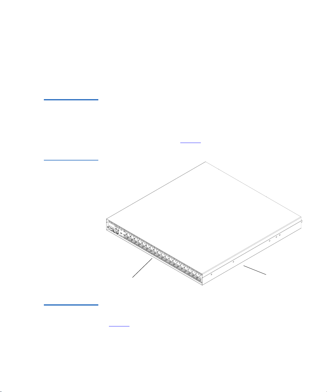
Figure 1 DX-Series
System Components
Chapter 1 DX-Series System Description
DX-Series System
DX-Series controller
(SP100)
Ethernet switch
(DX100 only)
Fibre Channel switch
(DX100 only)
DX-Series storage array
AC power sequencer
(DX100 only)
Quantum DX-Series User’s Guide 5
Page 24
Chapter 1 DX-Series System Description
DX-Series System
Serial ATA hard drives are the heart of the DX-Series system. These hard
drives (1 drive per drive sled = 16 total drives) appear to the backup
application as up to 160 DLT tape cartridges per storage array (see
figure 2
).
Data is stored on the hard drives through an interface that appears as an
ATL P1000 tape library. This allows backup applications to recognize and
integrate a DX-Series system into a data center environment just like a
typical tape library.
Figure 2 DX-Series
Hard Drives
Hard drives
in drive sleds
Caution: Removing hard drives during system operation may cause
loss of data or degraded system performance. Contact
Quantum customer support (see
report any hard drive failure.
6 Quantum DX-Series User’s Guide
Contacts on page xvi) to
Page 25

Chapter 1 DX-Series System Description
Features and Benefits
Features and Benefits 1
The DX-Series system provides the following features and benefits:
• Restores files 5 to 10 times faster than a conventional tape library
• Up to 64TB (raw) capacity in 4TB increments (additional capacity
appears as extra virtual tape cartridges to the backup software)
• High availability features:
• RAID 5 file system with one LUN of 7+1 and one LUN of 6+1
with a global hot spare to ensure data protection even if one drive
fails (Optional RAID 5 with zero or two hot spares)
• Event monitoring and logging
• Redundant cooling, power supplies, and disk parity protection
• Global spare and hot-swappable hard drives
• Up to two RAID controllers per storage array
• Flexible alert notification including e-mail and SNMP traps
• 3.25 TB (6.5 TB with 2:1 compression) usable capacity per storage
array (with one global hot spare, maximum of four in a DX30 and
sixteen in a DX100) in RAID 5 configuration (This is the minimum
capacity, check the DX-Series Management Home page for exact
capacity.)
• Serial ATA drive technology
• Restore latency under 10 seconds
• Two 2 Gbit/sec Fibre Channel interfaces for DX30; eight for DX100
• Hardware based 2:1 compression capability
• 10/100/1000 BaseT Ethernet interface for auxiliary management
functionality (web based management)
• Browser based remote management system that provides status and
configuration options
• Rack space requirements:
• DX30 base unit - 6U (15U with a maximum of 4 storage arrays)
• DX100 base unit - 12U (58U for a maximum of 16 storage arrays,
two Fibre Channel switches, eight AC power sequencers, and an
Ethernet switch)
Quantum DX-Series User’s Guide 7
Page 26

Chapter 1 DX-Series System Description
DX-Series Components
• Emulates 1 to 24 tape drives and supports up to 24 concurrent backup
streams for DX100, up to 6 for DX30
• User-selectable cartridge count between 4 and 2560 tape cartridges
for DX100, and 2 to 640 for DX30
• Quantum DLT7000 and ATL P1000 emulation
• Supported by every major backup software vendor preserving
software investment
• Installs in a standard rack with a minimum depth of 30 in (76.2 cm)
DX-Series Components 1
The DX-Series system consists of the following major components:
• DX-Series Storage Array
• DX-Series Controller
DX-Series Storage Array
• Fibre Channel Switch (DX100 Only)
• Ethernet Switch (DX100 Only)
• AC Power Sequencer (DX100 Only)
Up to four storage arrays can be installed in a DX30 system and up to
sixteen storage arrays can be installed in a DX100 system. The storage
1
array houses the following components:
• Drive sleds (16 per storage array)
• Two redundant power supplies
• Two redundant fan modules
• RAID controller(s) (contains Fibre Channel interfaces)
• DX30 contains a single RAID controller
• DX100 contains dual RAID controllers
These components are removed and replaced either through the front or
back of the array (see figure 3
).
8 Quantum DX-Series User’s Guide
Page 27
Figure 3 DX-Series
Storage Array
Chapter 1 DX-Series System Description
DX-Series Components
DX-SeriesDrive sleds
storage array
DX-Series Controller
RAID Sets 1
The DX-Series storage array is divided into two RAID sets. The first RAID
set is made up of the first eight drive sleds (sleds 1-8). The second RAID
set is made up of the next seven drive sleds (sleds 9-15). The last hard
drive (drive sled 16) is reserved as a global hot spare. Each RAID set can
sustain a single drive sled failure and can hold a maximum of 80 virtual
tape cartridges. A maximum of 160 virtual tape cartridges are held within
a storage array.
Drive Sleds 1
Each drive sled located on the front of the DX-Series storage array
contains one hard drive.
The DX-Series controller contains a Linux based operating system that
provides the library and tape drive emulation as well as Fibre Channel
1
and Ethernet interfaces (see
Quantum DX-Series User’s Guide 9
figure 4).
Page 28

Chapter 1 DX-Series System Description
DX-Series Components
Figure 4 DX-Series
Controller
DX-Series
controller
Ethernet Interface 1
The Ethernet port is provided for remote management of the DX-Series
controller via web-based configuration and management screens
(see DX-Series Remote Management
on page 27).
Fibre Channel Interfaces 1
Channel network at the customer site as well as the DX-Series storage
arrays in the system.
The DX30 contains the following Fibre Channel HBAs:
• A dual port Fibre Channel HBA (connects to customer Fibre Channel
network)
• A quad port Fibre Channel HBA (connects to DX-Series storage
arrays)
The DX100 contains the following Fibre Channel HBAs:
• Four dual port Fibre Channel HBAs (connects to customer Fibre
Channel network)
10 Quantum DX-Series User’s Guide
Page 29
Chapter 1 DX-Series System Description
DX-Series Components
• Two quad port Fibre Channel HBA (connects to DX-Series storage
arrays)
This connection can be a direct connection to the Fibre Channel host or to
a Fibre Channel switch. The Fibre Channel interface automatically detects
the mode being used by the network and sets itself appropriately.
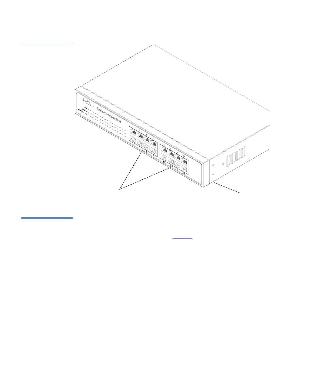
Fibre Channel Switch (DX100 Only)
Figure 5 Fibre
Channel Switch
The Fibre Channel switch provides twenty ports for connecting up to
eight storage arrays to the DX-Series controller. Each storage array has
two connections to the Fibre Channel switch for redundancy and
1
improved performance. One Fibre Channel switch is required for two to
eight storage arrays; a second Fibre Channel switch is required for nine to
sixteen storage arrays (see
figure 5).
Fibre Channel
switchPorts
Ethernet Switch (DX100 Only)
The Ethernet switch provides 16 ports for connecting the AC power
sequencer and Fibre Channel switch to the DX-Series controller (see
1
figure 6).
Quantum DX-Series User’s Guide 11
Page 30
Chapter 1 DX-Series System Description
DX-Series Components
Figure 6 Ethernet
Switch
Ports
AC Power Sequencer (DX100 Only)
12 Quantum DX-Series User’s Guide
The AC power sequencer (two power sequencers for every four storage
arrays) are programmed by the DX-Series controller to power on the
1
storage arrays in proper order (see
figure 7).
Ethernet
switch
Page 31

Figure 7 AC Power
Sequencer
Chapter 1 DX-Series System Description
Supported RAID Configurations
AC power
sequencer
Supported RAID Configurations 1
RAID is short for Redundant Array of Independent (or Inexpensive)
Disks, which is a category of hard disk drives that employ two or more
drives in combination for fault tolerance and performance. There are a
number of RAID levels in use today such as 0, 1, 3, 5, and 10.
The DX-Series system supports RAID 5 in both 7+1 and 6+1 with hot
spare configurations.
Quantum DX-Series User’s Guide 13
Page 32

Chapter 1 DX-Series System Description
Supported RAID Configurations
RAID 5 Configuration
The RAID 5 configuration is the most common RAID level in use today.
RAID 5 minimizes the write bottlenecks of other RAID levels by
1
distributing parity stripes over a series of hard drives. In doing so it
provides relief to the concentration of write activity on a single drive,
which in turn enhances overall system performance. Instead of allowing
any one drive in the array to assume the risk of a bottleneck, all of the
drives in the array assume write activity responsibilities. The distribution
frees up the concentration on a single drive, improving overall subsystem
throughput.
The RAID 5 parity encoding scheme maintains the system’s ability to
recover any lost data should a single drive fail. This can happen as long as
no parity stripe on an individual drive stores the information of a data
stripe on the same drive. In other words, the parity information for any
data stripe must always be located on a drive other than the one on which
the data resides (see figure 8
).
Note: The DX-Series storage array is shipped with the following
RAID configuration:
• 1 LUN configured in RAID 5 (7 data drives + 1 parity
drive)
• 1 LUN configured in RAID 5 (6 data drives + 1 parity
drive)
• 1 global hot spare drive
To reconfigure the DX-Series storage array to either remove
the hot spare or add an additional hot spare (total of two hot
spares), contact Quantum customer support (see Customer
Support on page xvi). Reconfiguring the storage array RAID
configuration will cause all previously stored data to be lost.
14 Quantum DX-Series User’s Guide
Page 33

Figure 8 RAID 5
Configuration
Data stripe
Chapter 1 DX-Series System Description
Typical Configurations
Data stripe A
Data stripe B
Data stripe C
Data stripe D
Data stripe E
A0 A1 A2 A3
B0 B1 B2
C0 C1 3 parity C3 C4
D0
1 parity
Drive 0 Drive 1 Drive 2 Drive 3 Drive 4
2 parity
E1 E2 E3 E4
D2 D3 D4
4 parity
0 parity
B4
Typical Configurations 1
The DX-Series system has many advantages over typical tape cartridge
based systems such as faster data transfer, instant availability, and
greater reliability. You can add storage arrays to the system to increase
storage capacity.
To take advantage of the DX-Series systems speed and reliability and still
have the safety of off-site storage, Quantum recommends exporting the
data from the DX-Series system to an automated tape library (see
figure 9
as the saftey of off-site backups on tape cartridges. Storage management
software applications often refer to this operation as “cloning” or
“vaulting.” Check with your software supplier for information on
enabling this feature.
). This configuration still allows fast backup and restores as well
Quantum DX-Series User’s Guide 15
Page 34

Chapter 1 DX-Series System Description
Typical Configurations
Figure 9 DX-Series
System Plus a Tape
Client
Library
Data
Server
SAN
Tape Library
(ex. Quantum P4000)
DX-Series
16 Quantum DX-Series User’s Guide
Page 35

Chapter 2
2Basic Operations
Although the vast majority of DX-Series system operations are handled
through the DX-Series Remote Management
system operations include:
• Turning on the DX-Series Components
• DX-Series Controller Operations
• DX-Series Storage Array Operations
• Relocating the DX-Series System
on page 27, basic DX-Series
T urning on the DX-Series Components 2
The power on procedure differs depending on the DX-Series system
(DX30 or DX100). Refer to the following section to turn on the DX-Series
system:
• Turning on the DX30
• Turning on the DX100
Quantum DX-Series User’s Guide 17
Page 36

Chapter 2 Basic Operations
Turning on the DX-Series Components
Turning on the DX30
Turning on the DX100
The DX30 components must be turned on in the following order:
2
• DX-Series storage array(s)
• DX-Series controller
To turn on the DX30 system (see figure 10):
1 Turn on both power switches on all DX-Series storage arrays.
2 Turn the DX30 controller on by pushing the power button located on
the front of the unit
The DX100 must be powered on in the following sequence (see figure 10):
2
1 Turn on both power switches on the storage arrays (they will not
power on yet).
2 Turn on the circuit breakers of the AC power sequencers.
3 Wait for all of the storage arrays to become ready.
4 Turn on the DX100 controller.
18 Quantum DX-Series User’s Guide
Page 37

Figure 10 Power
Switch Locations
Chapter 2 Basic Operations
DX-Series Controller Operations
Controller
Power
AC power sequencer
(DX100 only)
Storage arrayPower
Power
DX-Series Controller Operations 2
The DX-Series controller contains the Linux operating system as well as
the Fibre Channel HBAs connecting the unit to the storage arrays and to
the customer host systems.
The front panel of the controller has a series of buttons and LED
indicators (see figure 11
Quantum DX-Series User’s Guide 19
).
Page 38

Chapter 2 Basic Operations
DX-Series Controller Operations
Figure 11 Controller
Front Panel
Power button
System reset
Hard drive
activity
Alarm reset
Network
port 2
Power indicator
Network
port 1
Fan status
Power supply
status
Table 1 Controller
Front Panel
Button/LED Description
Power button Powers the controller on or off
System reset Resets the controller
Alarm reset Resets the alarm after a failure occurred
Power indicator This LED is lit when the controller is on
20 Quantum DX-Series User’s Guide
Page 39

Chapter 2 Basic Operations
DX-Series Storage Array Operations
Button/LED Description
Hard drive activity This LED flashes when the flash disk is
active
Network port 1 This LED flashes indicating activity on the
first network port
Network port 2 This LED flashes indicating activity on the
second network port
Power supply status Green indicates a good status on both power
supplies. Red indicates a single power
supply failure
Fan status Green indicates a good status on all internal
cooling fans. Red indicates at least one fan
failure.
DX-Series Storage Array Operations 2
This section describes how to monitor the DX-Series storage array.
System Monitoring 2
The DX-Series storage array can be monitored either through the front
LCD panel, various LEDs located on the front and back of the unit, and
also through an audible alarm.
Storage Array LCD 2
The storage array LCD is located in the upper left corner of the unit (see
figure 12
).
Quantum DX-Series User’s Guide 21
Page 40

Chapter 2 Basic Operations
DX-Series Storage Array Operations
Figure 12 Storage
Array LCD Location
Power
Busy
Attention
Up and down
arrows
Mute button
The LEDs located to the left side of the front LCD are described in table 2.
Quantum DX
Ready
Table 2 Front LED
Descriptions
LED On/Off Description
Power -
On The storage array is powered on.
Blue
Off The storage array is powered off.
Busy -
On The host or drive channel is active.
White
Off There is no host or drive activity.
Attention -
Red
On System status events have been detected by
the firmware. Use the up and down arrows
on the LCD to view the events.
Off All system components are functioning
normally.
22 Quantum DX-Series User’s Guide
Page 41

Figure 13 RAID
Controller Locations
Chapter 2 Basic Operations
DX-Series Storage Array Operations
LED On/Off Description
Button Description
Mute button Press the mute button to stop the alarm.
RAID Controller LEDs 2
The RAID controller LEDs are located in the back of the storage array (see
figure 13
). The DX30 storage array contains a single RAID controller
located in the upper bay and the DX100 storage array contains dual RAID
controllers.
The LEDs located on the RAID controller are described in table 2.
Quantum DX-Series User’s Guide 23
Page 42

Chapter 2 Basic Operations
DX-Series Storage Array Operations
Table 3 RAID
Controller LED
Descriptions
LED On/Flash/Off Description
1: Controller
Ready -
Green
On Indicates that the RAID
controller is active and operating
properly.
Flashing The RAID controller is
initializing.
Off The RAID controller is not ready
for operation.
2: FC Host
Ports Active
Flashing There is activity on the Fibre
Channel host.
- Green
Off There is no activity on the Fibre
Channel host.
3: SATA
Device Ports
Flashing There is activity on the SATA
drive ports.
- Green
Off There is no activity on the SATA
drive ports.
4: Partner
Failed
On Indicates that the partner
controller failed.
(DX100
only) -
Amber
Off The partner controller is
operating correctly.
5: Cache
Dirty
On The cache memory is dirty and is
being held up via the battery
backup unit (BBU).
6: BBU Fault
- Amber
On The BBU cannot sustain the
cache memory.
Off The BBU is able to sustain the
cache memory.
Slow flash The BBU is charging.
24 Quantum DX-Series User’s Guide
Page 43

Relocating the DX-Series System
LED On/Flash/Off Description
Chapter 2 Basic Operations
A: CH0 Link
- Green
B: CH1 Link
- Green
C: EXP Link
Green
Audible Alarm 2
Whenever any of the threshold values assigned to the different
components within the DX-Series storage array have been surpassed or
when an active component has failed, an audible alarm is triggered. To
determine what component has triggered the alarm, read the error
message on the LCD screen (see figure 12
On Channel 0 link is established.
Off Channel 0 link is not established
or is cut off.
On Channel 1 link is established.
Off Channel 1 link is not established
or is cut off.
On Expansion port link is
established.
Off Expansion port link is not
established or is cut off.
).
Relocating the DX-Series System 2
If you ever need to install the DX-Series system components in a different
location, refer to the “Quantum DX-Series Unpacking and Installation
Instructions” PN6513502 included on the documentation CD. These
instructions include hardware installation and cabling as well as software
configuration.
Quantum DX-Series User’s Guide 25
Page 44

Chapter 2 Basic Operations
Relocating the DX-Series System
26 Quantum DX-Series User’s Guide
Page 45

Chapter 3
3DX-Series Remote
Management
The DX-Series system utilizes a web-based interface which allows you to
configure and manage the DX-Series system from a remote workstation
on the same network. The DX-Series system is managed through the
following web pages (accessible using Internet browser software installed
on the host computer):
• Home allows you to view the status of all system components.
• Configuration allows you to set up information about the DX-Series
system such as network, date and time, passwords, and Fibre
Channel port settings and device mappings.
• System Status allows you to view the status of the emulated tape
drives, cartridges, and robot, as well as system performance.
• Remote Alerts allows you to set up e-mail messages and SNMP alerts
to alert you when certain events occur on the DX-Series system.
• Licensing allows you to view the license agreement as well as add
license keys to enable optional product features.
• Utilities allows you to upload and activate new firmware revisions as
well as configuration files.
Quantum DX-Series User’s Guide 27
Page 46

Chapter 3 DX-Series Remote Management
DX-Series Web Pages
DX-Series Web Pages 3
The Internet browser software is not supplied with the DX-Series system;
you must obtain and install it independently. The DX-Series system
supports the following Internet browsers:
• Microsoft Internet Explorer 6.0 or later
You can download this software from
http://www.microsoft.com.
Note: If Internet Explorer is the default browser on the client system:
• The latest security updates for Microsoft VM (virtual
machine) must be installed on the client system.
• The security settings must be set no higher than
“medium”. If the settings are set to “high security”, the
browser will not be able to login to the DX-Series system
since the system needs write access to the client.
DX-Series Web Page Menu Items
• The “Play animations in web pages” item in the Internet
Options/Advanced/Multimedia menu must be enabled.
• Netscape Navigator 7.1 or later
You can download this software from
http://www.netscape.com.
• Java Plug-in 1.4.2 or later
You can download this software from
http://www.java.com
The following figure depicts the menu items available from the DX-Series
Web pages.
3
28 Quantum DX-Series User’s Guide
Page 47

Figure 14 DX-Series
Web Page Menu
Items
Chapter 3 DX-Series Remote Management
DX-Series Web Pages
Login Home Configuration
Accessing DX-Series Web Pages
Quick Status Library
System
Details
System
Temperatures
System
Throughput
Partitions
Enable/Disable
Write Protection
Assign
Barcodes
Properties
Network
Date and
Time
Security
Monitor
Password
Administrator
Password
Fibre Channel
Configuration
Settings
Device
Mappings
Port
System
Status
Library
Drives
Storage
Bins
Robot
Hardware
Controller
Storage Arrays
FC Switches
Performance
Remote
Alerts
Email
Email
Notification
Email Server
Information
Test Email
System
SNMP
Trap
Selection
Trap
Destinations
Community
Management
Test SNMP
System
Contacts
Company
Information
Primary
Contact Info.
Secondary
Contact Info.
Licensing
Keys
End-User
Agreement
Utilities
Library
State
System
Log
Firmware
Upload
Configuration
Up/Download
Diagnostics
Shutdown
To access the DX-Series web pages:
3
1 On the host computer, open the Internet browser software.
2 In the Address field, type http://IPaddress/ where IP address is the IP
address for the DX-Series system.
The Log In page displays (see figure 15):
Quantum DX-Series User’s Guide 29
Page 48

Chapter 3 DX-Series Remote Management
DX-Series Web Pages
Figure 15 Login Page
3 Select the login type and enter the appropriate password.
Login Type Default Password Description
Monitor password The monitor user is
Administrator password The administrator user can
Note: The passwords must be lowercase and limited to 15
characters.
4 Click Login.
The Home page displays (see figure 16):
30 Quantum DX-Series User’s Guide
allowed to view the
DX-Series system
management pages, but
cannot change them.
both view and change the
management pages.
Page 49

Figure 16 Home Page
Banner
frame
Contents
frame
Management
frame
Chapter 3 DX-Series Remote Management
DX-Series Web Pages
System
temperature
and voltage
Quick status
Using the DX-Series Web Pages
System
throughput
The first page that displays after you login to the DX-Series web pages is
the DX-Series system
3
Home page (see figure 16). This page includes
information on the DX-Series system status as follows:
• Quantum DX-Series is on-line
• Quantum DX-Series is off-line
The Home page is divided into four distinct sections:
• Banner frame
• Contents frame
• Management frame
• Quick status information
Note: The
Home page display varies depending on the number of
storage arrays configured in your DX-Series system.
The banner frame displays the Quantum logo and product name. The
contents frame displays a list of the DX-Series web pages. To view a page,
Quantum DX-Series User’s Guide 31
Page 50

Chapter 3 DX-Series Remote Management
DX-Series Web Pages
click its corresponding link. The management frame displays the page
you selected.
Graphical View vs. Textual View 3
There are two options for viewing the system details from the Home page
(see figure 17
• Graphical view - system details are displayed in the management
frame using graphical representations of the DX-Series components
to describe the system status.
• Textual view - system details are displayed in the management frame
using text to describe the DX-Series system status.
Figure 17 System
Details (Graphical vs.
Textual)
):
32 Quantum DX-Series User’s Guide
Page 51

Chapter 3 DX-Series Remote Management
Configuration
Details Buttons (System Temperature/Voltage and Throughput) 3
Both the system temperature/voltage and throughput sections of the
home page have a details buttons.
• System Temperature/Voltage Details button: Click the system
temperature/voltage details button to go to the
Hardware page. This page provides more detailed information on the
system components (see
more information).
• Throughput Details button: Click the throughput details button to go
to the
System Status/Performance page. This page provides more
detailed system performance information (see
Performance on page 68 for more information).
To return to a previous web page, click the browser’s Back button.
Viewing Hardware Status on page 58 for
System Status/
Viewing System
Configuration 3
Accessing Library Configuration
This information was initially configured during the installation of the
DX-Series system.
To access the Configuration page, from the contents frame, click
Configuration.
3
The management frame displays the Configuration page (see figure 18).
Note: The DX-Series system must be offline before making any
changes to the system configuration. See Changing Library
State on page 83.
Quantum DX-Series User’s Guide 33
Page 52

Chapter 3 DX-Series Remote Management
Configuration
Figure 18 Configuration
Page
Partitioning 3
Partitioning provides the capability to divide the DX-Series virtual tape
drives and storage elements into separate partitions, usable by separate
host computers. The
Partitions page contains a list of unassigned tape
drives and cartridges as well as all user defined partitions currently
configured on the system. This page also contains the ability to add, edit,
and delete partitions.
Clicking on a partition name in the Partition list displays a detail window
listing all details for the selected partition (see figure 19
system status pages for details on the tape drives and tape cartridges.
34 Quantum DX-Series User’s Guide
). Refer to the
Page 53

Figure 19 Partition
Details
Partition name
Chapter 3 DX-Series Remote Management
Configuration
The library partitioning page is broken up into the following sections:
• Adding a Partition
• Editing a Partition
• Deleting a Partition
Adding a Partition 3
Up to two partitions can be added to a DX30 system. Up to eight
partitions can be added to a DX100 system.
Caution: Ensure that your backup package is properly configured
for the correct number of tape drives emulated in the
DX-Series system partition. Failure to do so may cause
your backup application to malfunction or cease to
operate.
Quantum DX-Series User’s Guide 35
Page 54

Chapter 3 DX-Series Remote Management
Configuration
To add a partition:
Note: To add, edit, or delete a partition, the system must be offline.
1 From the Partition page, click Add to add a partition to the system.
The Add Partition page displays (see figure 20).
Figure 20 Adding a
Partition
2 Enter a partition name that identifies it so it can be distinguished
from other partitions on the DX-Series system.
Note: The partition name is independent of the host name in the
Network tab (see Configuring the Network on page 43).
3 Select the inquiry identity to determine the inquiry string returned
from the DX-Series system. If you select
appears as an ATL P1000 to the host and backup application. If you
36 Quantum DX-Series User’s Guide
ATL P1000, the DX-Series
Page 55

Chapter 3 DX-Series Remote Management
Configuration
select Quantum DX30 or Quantum DX100, the host and backup
application recognize the device as a
DX100
respectively.
Quantum DX30 or Quantum
Note: Quantum recommends that the device configuration be set
to
ATL P1000 unless your specific backup application
supports the DX-Series inquiry strings. If your backup
application does support DX30 and DX100, you should
select that setting for improved performance.
4 Select the number of tape drives (emulated DLT7000) available to the
host and backup application in this partition. The Default partition
contains 6 tape drives at the time of installation, however, you can
change the number of drives (DX30 up to 6 tape drives; DX100 up to
24 tape drives).
Note: If all tape drives are assigned to other partitions, you must
unassign one or more tape drives to make them available
for a new partition. Be aware that in a DX30, all tape drives
are assigned to the Default partition at the time of
installation.
5 Enter the number of empty bins available in addition to the number
of cartridges created in the partition. The default number of empty
bins is 0 and up to 28 empty bins can be selected.
6 Select the number of tape cartridges from the A vailable Tape Cartridge
list and click the right arrow button to move the cartridges into the
partition.
Note: If all tape cartridges are assigned to other partitions, you
must unassign one or more tape cartridges to make them
available for a new partition. Be aware that all cartridges
that were created at the time of installation (see Creating
Cartridges on page 116) are assigned to the Default
partition.
7 Click Apply to create the partition.
Map the Fibre Channel ports as described in Configuring the Fibre
Channel Options on page 48.
Quantum DX-Series User’s Guide 37
Page 56

Chapter 3 DX-Series Remote Management
Configuration
8 Return the DX-Series system to the on-line state (see Changing
Library State on page 83).
The partition is added to the partition list. To add another partition,
repeat this procedure.
Editing a Partition 3
To edit a partition:
Note: To add, edit, or delete a partition, the system must be offline.
1 From the Partition page, click the link for the partition you wish to
edit.
The Edit Partition page displays (see figure 21).
Figure 21 Editing a
Partition
2 Edit the partition information as desired (see Adding a Partition on
page 35 for descriptions of the fields).
3 Click Apply.
38 Quantum DX-Series User’s Guide
Page 57

Chapter 3 DX-Series Remote Management
Configuration
4 Return the DX-Series system to the on-line state (see Changing
Library State on page 83).
The partition is updated.
Deleting a Partition 3
To edit a partition:
Note: To add, edit, or delete a partition, the system must be offline.
1 From the Partition page, click the link for the partition you wish to
delete.
The Edit Partition page displays (see figure 21).
2 Click Delete to delete the partition.
3 Return the DX-Series system to the on-line state (see Changing
Library State on page 83).
Write Protection 3
The partition is deleted.
Write protection, when enabled, prevents any data to be written to the
tape cartridge. This protects your important data from being overwritten. The cartridge will remain unavailable for further storage until
the write protection has been disabled.
Note: To enable or disable write protection, the system must be
offline.
To enable/disable write protection:
1 From the Library page, click the Write Protection link.
The Write P rotection page displays (see figure 22).
Quantum DX-Series User’s Guide 39
Page 58

Chapter 3 DX-Series Remote Management
Configuration
Figure 22 Enabling/
Disabling Write
Protection
Available tape
cartridge list
Write protect
enable/disable
Apply button
2 Select the tape cartridges from the Available Tape Cartridge list and
click the right arrow button to move them into the
Cartridge
list. You can sort the tape cartridges by barcode, partition,
location, and used. You can show all cartridges, unassigned
cartridges, or by partition assignment.
Tapes configuration
page
Selected Tape
3 Check Enable Write-Protection Selected Tape(s) to ENABLE write
protection on the selected tape cartridges or un-check the WriteProtection Select Tape(s) to DISABLE write protection on the selected
tape cartridges.
4 When you have selected the tape(s) and write protection status, click
Apply.
Write protection for the selected tapes is enable/disabled.
Barcode Assignment
Barcode labels provide individual identities for each tape cartridge in the
system. These labels allow the DX-Series system and third-party backup
3
applications to track and differentiate between the tape cartridges within
the system.
40 Quantum DX-Series User’s Guide
Page 59

Figure 23 Assigning
Barcode Labels
Chapter 3 DX-Series Remote Management
Configuration
Barcode labels are automatically assigned during the DX-Series system
initialization. These barcode labels can be over-ridden if necessary.
Note: To assign a barcode label, the system must be offline.
To assign a barcode label to a tape cartridge(s):
1 From the Library link of the Configuration page, click the Barcode
Assignment
link.
The Barcode Assignment page displays (see figure 23).
Tapes configuration page
Available tape
cartridge list
New alpha-numeric
prefix
Numeric ending
Apply button
2 Select the tape cartridges from the Available Tape Cartridge list and
click the right arrow button to move them into the
Cartridge
list.
Quantum DX-Series User’s Guide 41
Selected Tape
Page 60

Chapter 3 DX-Series Remote Management
Configuration
3 Enter the alpha characters (0 to 6 characters) in the New Alpha Prefix
field.
Note: If you are entering alpha characters for the first part of a
4 Enter the numeric character in the Numeric Ending field.
Note: This number is used as the first number in the range of
5 When you have selected the tape(s) and both the alpha and numeric
characters, click
Barcode labels are assigned for the selected tape(s).
barcode number and this is the first number in a range, no
more than five characters can be used. This allows the
system to assign the last character in the field.
tape cartridges. The number will increment with each
additional cartridge in the field.
Apply.
Properties 3
The library name identifies the DX-Series system so it can be
distinguished from other devices on the network through the SNMP
interface.
To set the library name:
1 From the Library link of the Configuration page, click the Properties
link.
The Properties page displays (see figure 23).
42 Quantum DX-Series User’s Guide
Page 61

Figure 24 Assigning a
Library Name
Chapter 3 DX-Series Remote Management
Configuration
2 Enter a library name and click Apply.
Configuring the Network
The DX-Series system will use the new library name the next time the
system is rebooted.
Note: The library name is independent of the host name in the
Network tab (see Configuring the Network on page 43).
The network configuration information was entered during the initial
setup of the DX-Series system. Consult your network administrator prior
3
to changing any of the information.
Viewing/Editing Network Configuration 3
1 To access the Network Configuration page, from the Configuration
page, click
Network.
The management frame displays the Network Configuration page (see
figure 25).
Quantum DX-Series User’s Guide 43
Page 62

Chapter 3 DX-Series Remote Management
Configuration
Figure 25 Network
Configuration Page
2 Edit the configuration information as desired (see table 4 for a
description of the fields).
3 Click Apply.
The DX-Series system will not use the new basic configuration until it
Table 4 Network
Configuration Fields
has been rebooted (see
Field Description
Hostname
Domain Name
Rebooting the DX-Series System on page 90).
View or set the hostname for the DX-Series system
View or set the domain name for the DX-Series
system.
IP Address
View or set the IP address for the DX-Series
system.
Network Mask
View or set the network mask for the DX-Series
system
44 Quantum DX-Series User’s Guide
Page 63

Field Description
Chapter 3 DX-Series Remote Management
Configuration
Configuring the Date and Time
Figure 26 Date and
Time Configuration
Default Gateway
View or set the default gateway for the DX-Series
system
Link Speed &
Duplex
View and set the link speed and duplex for the
DX-Series system (10/100/half/full/auto)
The date and time can be set from the DX-Series system web pages.
Setting the correct date and time allows the DX-Series system to provide
3
accurate reports when events occur on the DX-Series system.
Configuring the Data and Time 3
To access the Date and Time Configuration page:
1 In the Configuration page, click Date & Time.
The management frame displays the Date & Time Configuration page
(see
figure 26).
Quantum DX-Series User’s Guide 45
Page 64

Chapter 3 DX-Series Remote Management
Configuration
2 There are two options for setting the system date and time:
a Select Manual to manually set the system date and time using the
Change button for the system date and drop down boxes for the
system time.
b Select Use NTP (Network Time Protocol) to synchronize the
DX-Series system to an NTP server. The “Select a Server”
selection makes a list of well-known NTP servers such as the U.S.
Naval Observatory Master Clocks in Washington, DC and
Colorado Springs, Colorado available. The “Specify server”
selection enables you to type the name or IP address of any
desired NTP server. NTP sends periodic time requests to the DXSeries system, obtaining time stamps and using them to adjust
the system’s clock.
Configuring the Security Options
The DX-Series system has two levels of security built into the system:
Monitor and Administrator. The monitor user is allowed to view the
3
DX-Series system management pages, but not change them. The
administrator user can both view and change the management pages.
This section allows you to change the passwords for these accounts.
Accessing/Changing the Security Options 3
To access the Security page:
1 In the Configuration page, click Security.
The management frame displays the Security page (see figure 27).
46 Quantum DX-Series User’s Guide
Page 65

Figure 27 Security
Configuration
Chapter 3 DX-Series Remote Management
Configuration
2 Under Monitor Password, enter the desired password in the New
Password
field and again in the Confirm New Password field.
Note: The passwords must be lowercase and limited to 15
characters.
3 Click Apply.
A Results page indicates the password has been changed.
4 Under Administrator Password, enter the desired password in the
New Password field and again in the Confirm New Password field.
Note: The passwords must be lower case and limited to 15
characters.
5 Click Apply.
A Results page indicates the password has been changed.
Quantum DX-Series User’s Guide 47
Page 66

Chapter 3 DX-Series Remote Management
Configuration
Configuring the Fibre Channel Options
Figure 28 Fibre
Channel Input Port
Locations
The DX-Series system allows you to control and configure each of the
Fibre Channel input ports that connect to the customer SAN. The Fibre
Channel input ports are numbered 5 through 12 on the DX100 and 5
3
through 6 on the DX30 (see
DX100 back view (physical configurable ports)
figure 28).
12
567891011
DX30 back view (physical configurable ports)
To access the Fibre Channel page (see figure 29):
1 In the Configuration page, click Fibre Channel.
The management frame displays the Fibre Channel Port Settings page
(see
figure 29).
48 Quantum DX-Series User’s Guide
65
Page 67

Figure 29 Fibre
Channel Configuration
Chapter 3 DX-Series Remote Management
Configuration
Note: The DX-Series system must be off-line to configure the
Fibre Channel options.
2 While the Port WWNs are always unique, the Node WWNs can be set
according to the
Make the Node WWN section as follows:
a Selecting Globally Unique but same for all ports makes the Node
WWNs the same for all Fibre Channel ports.
b Selecting Equal to the Port WWNs for each port makes the Node
WWNs equal to the Port WWNs.
3 Selecting The Port Settings page (see table 5 for field descriptions)
allows you to set the AL_PA, Loop ID and link speed for each Fibre
Channel port connecting the DX-Series system to the customer SAN
(DX30 has two ports and DX100 has eight ports).
Quantum DX-Series User’s Guide 49
Page 68

Chapter 3 DX-Series Remote Management
Configuration
Table 5 Port Settings
Field Description
Node World
Wide Name
(WWN)
The node WWN is the overall system
identification on the customer SAN. This field
allows you to set the WWN in case a controller
is replaced so the customer SAN will not
require remapping.
AL_PA and
Loop ID
This field allows you to set either a soft or hard
AL_PA. Soft allows the customer SAN to
automatically assign a loop ID to the DX-Series
System. Hard allows you to manually assign
the loop ID. The Default setting is soft.
Speed
This field allows you to select the maximum
link speed of the Fibre Channel port (1GB/sec,
2GB/sec, or Automatic). The default setting is
Automatic.
4 To map specific devices to Fibre Channel ports, click Device Mapping.
The Device Mapping page displays (see figure 30).
50 Quantum DX-Series User’s Guide
Page 69

Figure 30 Device
Mapping Configuration
Chapter 3 DX-Series Remote Management
Configuration
The Device Mapping page allows you to map or assign DX-Series
virtual devices (robot and tape drives) to specific Fibre Channel
ports. The default setting for both the DX30 and DX100:
• Port 5 is assigned the robot and tape drives 0 through 2.
• Port 6 is assigned tape drives 3 through 5.
5 There are two ways to assign virtual devices to a specific Fibre
Channel port:
a Click Auto Populate to allow the DX-Series controller to
automatically assign virtual devices to a Fibre Channel port. The
controller assigns a robot and partition to each port.
Example: A system with 1 partition would have a robot assigned
to LUN 0 and all other devices within that partition assigned to
additional LUNs on that port.
b Use the drop down boxes located under the port number to select
the devices mapped to that port. Do NOT assign the same device
to more than one port unless your backup application can
support multiple mappings of the same device to more than one
port.
Quantum DX-Series User’s Guide 51
Page 70

Chapter 3 DX-Series Remote Management
System Status
Example: Assign the robot and tape drives 0 and 1 to port 5. From
the host, only the robot and tape drive 0 and 1 are visible from
port 5. Assign tape drive 2 and 3 to port 6. Only tape drive 2 and
3 are visible from port 6.
6 When all of the virtual devices have been assigned to the appropriate
port, click
Note: Microsoft Windows has a known issue recognizing more
The settings will take effect after the next system reboot (see
Rebooting the DX-Series System on page 90).
Apply to accept the port settings.
than eight LUNs on a single Fibre Channel port. See
Microsoft Knowledge Base Article 310072:
http://support.microsoft.com/default.aspx?scid=kb;en-us;310072
for information on reconfiguring Windows to overcome
this limitation.
System Status 3
The System Status page allows you to view information on the emulated
tape drives, robot, storage bins, and DX-Series system hardware.
Accessing System Status
52 Quantum DX-Series User’s Guide
To access the System Status page, from the contents frame, click System
Status
3
.
The management frame displays the System Status page (see figure 31).
Page 71

Figure 31 System
Status Page
Chapter 3 DX-Series Remote Management
System Status
The system status page provides two views for the system hardware:
• Physical View
The physical view displays the physical representation of the virtual
components (tape drives, tape cartridges, and robots) of the emulated
tape library. Each drive and tape cartridge is displayed in the tape
drive and storage bin sections. Clicking on a tape drive or cartridge
displays the specific details for that device on the right hand side of
the page.
Select the partition you wish to view from the drop down list. The
Show/Hide links will either display or hide information on the
selected tape drive, tape cartridge, or robot. Clicking on a tape drive,
tape cartridge, or robot displays detailed information about the
selected device.
• Logical View
A logical view displays the partitions within the DX-Series system.
Clicking on a partition displays the specific details for that partition
on the right hand side of the page.
Quantum DX-Series User’s Guide 53
Page 72

Chapter 3 DX-Series Remote Management
System Status
Viewing Tape Drive Details
Figure 32 Tape Drive
Details
Selected tape
drive
To view the tape drive details:
3
1 From the System Status page, select the partition from the drop down
list and click the tape drive you wish to view.
The tape drive details displays (see figure 32):
The tape drive details are shown in table 6.
Table 6 Tape Drive
Details
Field Description
Status Displays the current drive status. The drive can
be reading, writing, or idle.
Compression Displays the compression status, either enabled
or disabled.
54 Quantum DX-Series User’s Guide
Tape drive details
Page 73

Chapter 3 DX-Series Remote Management
System Status
Field Description
Contents Displays the current contents of the tape drive. If
a tape cartridge is present in the drive, the
cartridge label will display in the contents field
as well as the write protect status and capacity
information.
Brand Displays the manufacturer of the tape drive.
Model Displays the model of the tape drive.
Serial Number Displays the tape drive serial number.
LUN Displays the logical unit of the tape drive.
Port Displays the port number assigned to the tape
drive.
Viewing Robot Details
To view the robot details:
3
1 From the System Management page, click Show Robots to view the
details.
The robot details displays (see figure 33):
Quantum DX-Series User’s Guide 55
Page 74

Chapter 3 DX-Series Remote Management
System Status
Figure 33 Robot
Details
Robot
Table 7 Robot Details
Robot details
The robot details are shown in table 7.
Field Description
Status Displays the current status of the robot.
Contents Displays the current contents of the robot. If a
cartridge is present, the bar code label appears in
the robot contents.
Brand Displays the robot brand name.
Model Displays the robot model number.
Serial Number Displays the robot serial number.
56 Quantum DX-Series User’s Guide
Page 75

Chapter 3 DX-Series Remote Management
System Status
Viewing Storage Bin Details
Figure 34 Storage Bin
Details
Storage
bin
To view the storage bin details:
3
1 From the System Management page, click the storage bin to view the
details.
The storage bin details displays (see figure 34):
The storage bin details are shown in table 8.
Quantum DX-Series User’s Guide 57
Storage bin details
Page 76

Chapter 3 DX-Series Remote Management
System Status
Table 8 Storage Bin
Details
Viewing Hardware Status
Field Description
Status Displays the current status of the storage bin.
The status is either accessible or not accessible.
Contents Displays the current contents of a storage bin. If
a tape cartridge is present in a bin, the cartridge
label will display in the contents field as well as
the write protect status and capacity
information.
Compression
Information
Displays the compression ratio as well as the
uncompressed usage.
The DX-Series system provides a variety of hardware information from
the
3
Hardware Status page. The Hardware Status page gives the current
status of the hard drives, power supplies, fan modules, and temperature
of the controller, Fibre Channel switch and storage arrays.
To view the hardware status:
1 From the System Status page, click Hardware tab to view the
hardware status.
The Hardware Status page displays (see figure 35):
58 Quantum DX-Series User’s Guide
Page 77

Figure 35 Hardware
Status Page
Controller
Fibre Channel switch
(only present in DX100
systems)
Storage arrays
Chapter 3 DX-Series Remote Management
System Status
Controller Details 3
To view the details or status of the controller hardware, click on the
controller icon on the
The
Controller details display (see figure 36).
Quantum DX-Series User’s Guide 59
Hardware Status screen shown in figure 35.
Page 78

Chapter 3 DX-Series Remote Management
System Status
Figure 36 Controller
Details
Controller
status and
temperature
Controller details
Table 9 Controller
Temperature Details
Normal
Field Description
Controller
Temperature
Displays the current temperature of
the DX-Series system’s internal CPU
State
as well as the external system
temperature. There are three states
displayed: normal, warning, and
failed. The warning and failed states
also display a flashing amber box
around the temperature gauge for
warning and a red box for failed. If
the controller reaches 50°C (122°F),
a failure is displayed.
60 Quantum DX-Series User’s Guide
Warning
State
Failed
State
Page 79

Chapter 3 DX-Series Remote Management
Table 10 Controller
Fan and Power
Supply Status
Field Description Failed State
Power Supplies Displays the current status of the power
supplies. If a power supply has failed, contact
Quantum Customer Support (see Customer
Support on page xvi).
Fan Modules Displays the current status of the fan modules. If
a fan module has failed, contact Quantum
Customer Support (see Customer Support
on
page xvi).
System Status
Table 11 Controller
Fibre Channel Ports
Details
Ports Description
FC 1 and FC 6 Displays the current status of the individual ports
on the quad port Fibre Channel HBA(s). These are
the Fibre Channel HBA(s) that connect the
controller to the storage arrays via the Fibre
Channel switch. The status can either be Up
(green) or Down (grey).
FC 2 through
FC 5
Displays the current status of the individual ports
on the dual port Fibre Channel HBA(s). These are
the Fibre Channel HBA(s) that connect the
controller to the customer Fibre Channel SAN.
The status can either be 1 Gigabit/2 Gigabit
(green) or Down (grey).
Fibre Channel Switch Details (DX100 Systems Only) 3
To view the details or status of the Fibre Channel switch, click on the
Fibre Channel switch icon on the
figure 35
The
.
Fibre Channel Switch screen display (see figure 40).
Hardware Status screen shown in
Quantum DX-Series User’s Guide 61
Page 80

Chapter 3 DX-Series Remote Management
System Status
Figure 37 Fibre
Channel Switch
Details
Fibre Channel
switch status and
temperature
Fibre Channel switch details
Figure 38 Fibre
Channel Switch
Temperature Details
Normal
Field Description
State
Temperature Displays the current temperature of
the Fibre Channel switch internal
CPU as well as the external system
temperature. There are three states
displayed: normal, warning, and
failed. The warning and failed states
also display a flashing amber box
around the temperature gauge for
warning and a red box for failed. If
the controller reaches 50°C (122°F),
a failure is displayed.
62 Quantum DX-Series User’s Guide
Warning
State
Failed
State
Page 81

Chapter 3 DX-Series Remote Management
Figure 39 Fibre
Channel Switch Fan
and Power Supply
Status
Field Description Failed State
Power Supplies Displays the current status of the power
supplies. If a power supply has failed, contact
Quantum Customer Support (see Customer
Support on page xvi).
Fan Modules Displays the current status of the fan modules. If
a fan module has failed, contact Quantum
Customer Support (see Customer Support
on
page xvi).
Storage Array Details 3
System Status
To view the details or status of a storage array, click on a storage array
icon on the
The
Storage Array Details screen display (see figure 40).
Hardware Status screen shown in figure 35.
Quantum DX-Series User’s Guide 63
Page 82

Chapter 3 DX-Series Remote Management
System Status
Figure 40 Storage
Array Details
Storage array
status and
temperature
Storage array details
Table 12 St orage
Array Hard Drive
Status
Normal
Field Description
Storage Array
Hard Drives
Displays the current status of the
hard drives within the DX-Series
State
storage arrays. The hard drive
states displayed are: normal,
rebuild, and failed. Rebuild
indicates the array is currently
rebuilding the data on a new
storage array hard drive. If a hard
drive has failed, contact Quantum
Customer Support (see Customer
Support on page xvi).
64 Quantum DX-Series User’s Guide
Rebuild
State
Failed
State
Page 83

Chapter 3 DX-Series Remote Management
Table 13 St orage
Array Fan and Power
Supply Status
Field Description Failed State
Power Supplies Displays the current status of the power
supplies. If a power supply has failed, contact
Quantum Customer Support (see Customer
Support on page xvi).
Fan Modules Displays the current status of the fan modules. If
a fan module has failed, contact Quantum
Customer Support (see Customer Support
on
page xvi).
Table 14 St orage
Array Temperature
Details
System Status
Field Description
Storage Array
Temperature
Displays the current storage array
temperature. There are three states
displayed: normal, warning, and
failed. The warning and failed states
also display a flashing amber box
around the temperature gauge for
warning and a red box for failed. If
the array reaches 47°C (117°F), a
high temperature warning is
displayed. If the array reaches 50°C
(122°F), a failure is displayed.
Normal
State
Quantum DX-Series User’s Guide 65
Warning
State
Failed
State
Page 84

Chapter 3 DX-Series Remote Management
System Status
Storage Array Properties 3
The Storage Array Status screen also provides a link to storage array
properties (see figure 41
Figure 41 Storage
Array Properties Link
).
Storage array properties
To view the storage array properties, click Properties.
The storage array properties screen displays (see figure 42
66 Quantum DX-Series User’s Guide
).
Page 85

Figure 42 Storage
Array Properties
Chapter 3 DX-Series Remote Management
System Status
Table 15 St orage
Array Properties
The storage array properties are shown in table 15.
Field Description
Serial Number Displays the serial number for the primary
controller in the storage array.
Firmware
Revision
Displays the firmware revision currently
running on the selected storage array.
RAID Mode Displays the current RAID configuration on the
storage array. Only RAID 5 is supported.
Host Number Displays the host number.
Channel Displays the controller SCSI channel in which
the selected storage array is connected.
SCSI ID Displays the selected storage array SCSI ID.
LUN Displays the selected storage array LUN.
Quantum DX-Series User’s Guide 67
Page 86

Chapter 3 DX-Series Remote Management
System Status
Viewing System Performance
Figure 43 Performance
Status Page
3
The DX-Series system provides tape drive performance information on
the
Performance Status page. The Performance Status page gives the
current throughput of the tape drives in use.
To view the performance status:
1 From the System Status page, click Performance tab to view the
hardware status.
The Performance Status page displays (see figure 43):
The Performance Status page displays all partitions and their
individual performance information.
2 Select a partition to view the performance statistics of the individual
devices within the partition.
The tape drives within the partition display (see figure 44).
68 Quantum DX-Series User’s Guide
Page 87

Figure 44 Tape Drive
Throughput
Chapter 3 DX-Series Remote Management
Remote Alerts
Remote Alerts 3
The Remote Alerts page allows you to setup the DX-Series system to send
email alerts when hardware or software events have occurred on the
system.
Accessing Remote Alerts
To access the Remote Alerts page, from the contents frame, click Remote
Alerts
3
.
The management frame displays the Remote Alerts page (see figure 45).
Quantum DX-Series User’s Guide 69
Page 88

Chapter 3 DX-Series Remote Management
Remote Alerts
Figure 45 Remote
Alerts Page
The Remote Alert s page is divided into three sections:
• Email Page
• SNMP Page
• Contacts Page
Email Page 3
1 To access the Email page, from the Remote Alerts page, click the Email
tab.
The management frame displays the Email tab (see figure 46).
70 Quantum DX-Series User’s Guide
Page 89

Figure 46 Email Tab
Chapter 3 DX-Series Remote Management
Remote Alerts
2 Edit the Email information as desired (see table 4 for a description of
the fields) and click Apply.
3 After editing the Email information, click the Send button to test the
notification system. A test email is send to the administrative
recipients. If the test is not successful, verify the email server
information and the administrative recipients list and try again.
The Email tab details are shown in table 16 and table 17.
Quantum DX-Series User’s Guide 71
Page 90

Chapter 3 DX-Series Remote Management
Remote Alerts
Table 16 Email
Notification
Field Description
Message Type:
Hardware Failure
When a hardware failure occurs on the
DX-Series system such as a transition to a
degraded, limited access, or failed system state,
an email is sent to everyone on the hardware
failure recipient list.
Message Type:
Configuration
Changes
When a configuration change is made on the
DX-Series system such as changing a bar code
label or network configuration, an email is sent
to everyone on the configuration changes
recipient list.
Message Type:
Operator Access
When an operator access occurs on the DX-Series
system such as starting up or shutting down the
system, an email is sent to everyone on the
operator access recipient list.
Message Type:
Soft Error
When a soft error has occurred on the DX-Series
system such as an attention state (high
temperature warning), an email is sent to
everyone on the soft error recipient list.
Message Type:
Used for testing the e-mail subsystem.
Administrative
New Recipient To add a new recipient to a specific list, type the
email address of the new recipient in the field
and click
Add.
Recipients Each message type has a recipients list that is
viewed by clicking on the specific drop-down
box. To remove a recipient, select the individual
email address from the list and click
Send to
Quantum?
To send an email notification to Quantum as
well as the recipients list, select the Send to
Quantum check box for the specific message
type. The company and contact information is
sent to Quantum as an attachment to this email.
72 Quantum DX-Series User’s Guide
Remove.
Page 91

Chapter 3 DX-Series Remote Management
Remote Alerts
Table 17 Email
Server Information
Field Description
Outgoing Email
Server Host
Name
Domain Name
Server IP
View or set the outgoing email server hostname
for the DX-Series system (for example, the DNS
name).
View or set the domain name server IP address
for the DX-Series system.
Address
SNMP Page 3
SNMP is short for Simple Network Management Protocol, a set of
protocols for managing complex networks. SNMP works by sending
messages, called protocol data units (PDUs), to different parts of a
network. SNMP-compliant devices, called agents, store data about
themselves in Management Information Bases (MIBs) and return this
data to the SNMP requesters.
1 To access the SNMP page, from the Remote Alerts page, click the
SNMP tab.
The management frame displays the SNMP tab (see figure 50).
Quantum DX-Series User’s Guide 73
Page 92

Chapter 3 DX-Series Remote Management
Remote Alerts
Figure 47 SNMP Tab
2 Enable the trap selections to be reported (see table 18):
Table 18 SNMP Trap
Selections
Field Description
Informational If selected,
Warning If selected,
Failure If selected,
Informational Traps are enabled.
Warning Traps are enabled.
Failure Traps are enabled.
Available If selected, a trap is generated every time the
library transitions from an unavailable to an
available state.
Unavailable If selected, a trap is generated every time the
library transitions from an available to an
unavailable state.
3 Click Apply.
A Results page displays indicating the configuration has been
changed.
74 Quantum DX-Series User’s Guide
Page 93

Figure 48 SNMP Trap
Destinations
Chapter 3 DX-Series Remote Management
Remote Alerts
4 Click New in the Trap Destination area (see figure 48), to set the IP
addresses that are to receive the traps generated by the DX-Series
system,
for example, 12.34.56.78. Up to five trap destination
addresses may be set. If less than five trap destinations are required,
leave unused
Trap Destination fields blank.
5 Click Add to add the IP address to the trap destinations and return to
the SNMP tab.
6 Click New in the Community Management area to edit the SNMP
communities (see
Quantum DX-Series User’s Guide 75
figure 49).
Page 94

Chapter 3 DX-Series Remote Management
Remote Alerts
Figure 49 SNMP
Community
Management
7 Under New Community, enter the new community information:
a A unique name in the Name field, the field holds up to 20
characters (a-z, A-Z), no special characters or blank spaces are
allowed
Caution: If no communities are defined, the DX-Series system is
universally accessible through a “public” community
(read-only).
b IP address in the IP Address field, if the value in the Network
Mask edit box ends in a zero, the value in the IP address edit box
must also end in a zero
c Subnet mask in the Network Mask field
Note: A single community with an IP address or network mask
set to
0.0.0.0, or left blank, indicates that IP-address-based
access control is disabled.
76 Quantum DX-Series User’s Guide
Page 95

Figure 50 Contacts
Tab
Chapter 3 DX-Series Remote Management
Remote Alerts
d Access rights for the new community:
• Get allows SNMP get operations:
• Get/Set allows both SNMP get and put operations
8 Click Add.
A Results page displays indicating the community has been added.
9 Click Send from the SNMP tab to send a test SNMP trap.
Contacts Page 3
1 To access the Contacts page, from the Remote Alerts page, click the
Contacts tab.
The management frame displays the Contacts tab (see figure 50).
2 Edit the configuration information as desired (see table 4 for a
description of the fields) and click Apply.
The Contacts tab details are shown in table 19 and table 20.
Quantum DX-Series User’s Guide 77
Page 96

Chapter 3 DX-Series Remote Management
Remote Alerts
Table 19 Company
Information
Field Description
Company Name View or edit the company name where the
DX-Series system resides.
Street View or edit the street name where the company
is located.
City View or edit the city where the company is
located.
State View or edit the state where the company is
located.
Postal Code View or edit the postal code.
Country View or edit the country where the company is
located.
DX-Series
System Location
Support
View or edit the physical location of the
DX-Series system (example: data center).
View or edit the support contract number.
Contract
Table 20 Primary/
Secondary Contact
Information
Field Description
Name View or edit the primary/secondary contact
name.
Email Address View or edit the primary/secondary contact
email address.
Phone View or edit the primary/secondary contact
phone number.
Fax View or edit the primary/secondary contact fax
number.
Pager View or edit the primary/secondary contact
pager number, if available.
78 Quantum DX-Series User’s Guide
Page 97

Chapter 3 DX-Series Remote Management
Licensing
Field Description
Street View or edit the primary/secondary contact
street address.
City View or edit the primary/secondary contact city
location.
State View or edit the primary/secondary contact
state location.
Postal Code View or edit the primary/secondary contact
postal code.
Country View or edit the primary/secondary contact
country location.
Licensing 3
The Licensing page allows you to add functionality to the DX-Series
system through license key activation and also allows you to view the
Quantum end user license agreement.
Accessing Licensing
To access the Licensing page, in the contents frame, click Licensing.
3
The management frame displays the Licensing page (see figure 51).
Quantum DX-Series User’s Guide 79
Page 98

Chapter 3 DX-Series Remote Management
Licensing
Figure 51 Licensing
Page
Keys Tab 3
The Licensing page contains:
• Keys Tab
• End User Agreement Tab
The Keys page is used to enable compression on the DX-Series system. If
compression is purchased with the DX-Series system, it is enabled at the
time of installation. If you wish to purchase a license key to enable
compression, contact Quantum to obtain a key for your system.
To activate a license key:
1 Access the Licensing page (see Accessing Licensing).
2 Click the Keys tab.
The Keys page displays (see figure 52).
80 Quantum DX-Series User’s Guide
Page 99

Figure 52 License
Keys Tab
Chapter 3 DX-Series Remote Management
Licensing
3 Enter the license key in the New Key edit box and click Add.
End User Agreement Tab
The license key is added to the installed keys list.
The End User Agreement Tab displays the entire end user agreement for
the DX-Series system.
3
To view the end user agreement:
1 Access the Licensing page (see Accessing Licensing).
2 Click the End-User Agreement tab.
The End-User Agreement page displays (see figure 53).
Quantum DX-Series User’s Guide 81
Page 100

Chapter 3 DX-Series Remote Management
Utilities
Figure 53 End User
Agreement Tab
Utilities 3
The Utilities page allows you to perform maintenance functions on the
DX-Series system, including uploading and activating software images,
and configuration files. The
shut down the DX-Series system.
Accessing Utilities 3
82 Quantum DX-Series User’s Guide
To access the Utilities page, in the contents frame, click Utilities.
The management frame displays the Utilities page (see figure 54).
Utilities page also allows you to restart or
 Loading...