

Page 1

Quantum PX720 Unpacking
and Installation Instructions
Introduction 3
Selecting an Installation Location 4
Floor Space..................................................................................................................4
Floor Clearance ..........................................................................................................5
Floor Strength and Inclination.................................................................................5
Power and Grounding ..............................................................................................5
Environmental Conditions.......................................................................................6
Preparing for the Installation 6
Providing Necessary Tools and Equipment..........................................................6
Taking ESD Precautions ...........................................................................................6
Unpacking the Library 7
Receiving the Library................................................................................................7
Unboxing the Library................................................................................................8
Positioning the Library ...........................................................................................11
Unpacking the Library............................................................................................13
Storing the Shipping Materials..............................................................................22
Leveling the Library................................................................................................22
Installing the Quantum PX720 Library 23
Cabling the Quantum PX720 ................................................................................23
Loading the Tape Cartridges .................................................................................34
Initial Configuration................................................................................................34
Document 6444602-03 A01, August 2004 1
Page 2

Quantum PX720 Unpacking and Installation Instructions
Document 6444602-03 A01
August 2004
2 6207947-05fN 19
Page 3
Quantum PX720 Unpacking and Installation Instructions
Document 6444602-03 A01
August 2004
Introduction 0
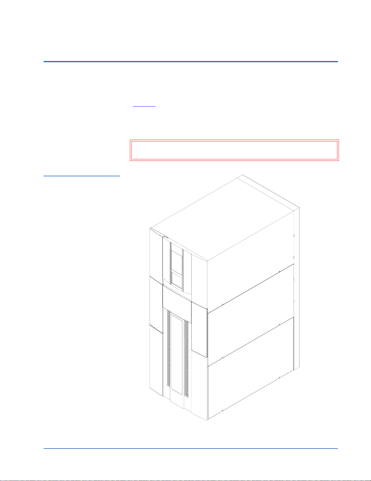
The Quantum PX720 is an automated storage and retrieval library consisting
of up to 20 tape drives and up to 642 SDLT or 726 LTO tape cartridges bins
(figure 1)
This document explains how to unpack the Quantum PX720. Once the library
is unpacked and moved to the desired installation location, set up the library
using the instructions in the Quantum PX720 Series User’s Guide.
Caution: Do NOT unpack the Quantum PX720 unless you are a
Figure 1 Quantum PX720
Library
.
qualified Quantum field service engineer.
Introduction 3
Page 4
Quantum PX720 Unpacking and Installation Instructions
Document 6444602-03 A01
August 2004
Selecting an Installation Location 0
When choosing an installation site for the PX720, consider the following
requirements:
• Floor space
• Floor clearance
• Floor strength and inclination
• Power and grounding
• Environmental conditions
These requirements are also described in the Quantum PX720 Series User’s
Guide.
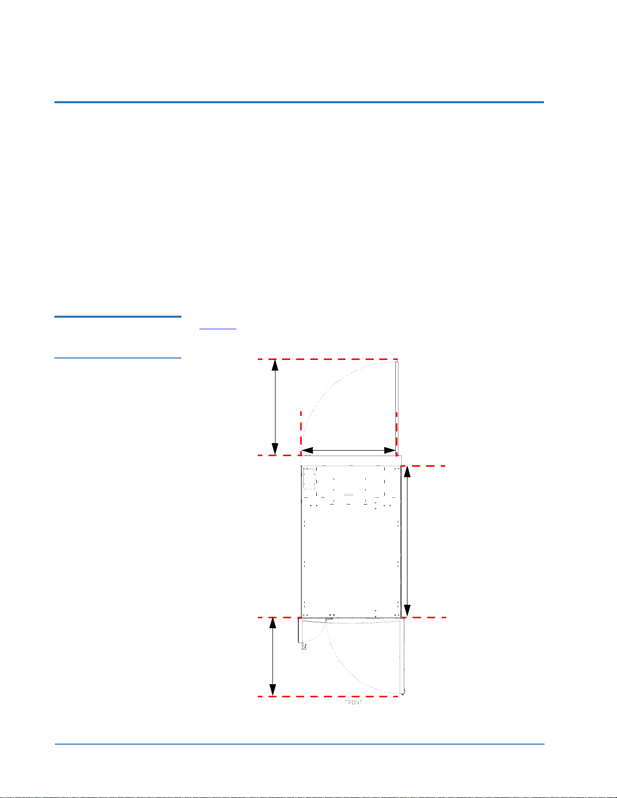
Floor Space 0 Figure 2 shows the minimum floor space required by the Quantum PX720.
Figure 2 Floor Space
Requirements
28 in. (71 cm)
30 in. (76 cm)
50 in. (127 cm)
23 in. (58 cm)
4 Selecting an Installation Location
Page 5

Quantum PX720 Unpacking and Installation Instructions
Document 6444602-03 A01
August 2004
Floor Clearance 0 The library has a floor clearance of 0.75 inch (19 mm). Place the library on a
level, uncarpeted floor free of defects.
Floor Strength and Inclination
0
The floor at the installation site must be rated at 250 lb/ft2
(1221 kg/m
2
). This is sufficient to support a fully loaded PX720 library.
The floor must be level to within 0.25 inch (6.4 mm) over a 6-foot-by-6-foot
(1.83-meter-by-1.83-meter) area.
Power and Grounding0 For the United States and Canada, two UL/CSA certified power cords are
furnished. Each uses a 14/3 SJT cord, a L6-20P plug, and an IEC-C320 C19
Figure 3 Power Supply
Cord
female connector (see figure 3
Connects to
wall outlet
Plug NEMA
L6-20P
).
Connects to library power supply
Connector IEC-C320 C19
The library is rated 200-240V~, 50-60Hz.
The library power requirements may require modification of the facilities
existing power capabilities by a qualified electrician. The required wall outlet
for the United States and Canada is rated at 250V 20A (see figure 4
).
Figure 4 Wall Outlet
Ground
Line x
Line y
Wall outlet:
NEMA L6-20R
rated 250V 20A
Two dedicated wall outlets and a 20 amp circuit breaker are required to
provide power to the PX720 library. Outside North America, replace the
supplied power cord with a harmonized 3 x 1.5 mm
2
power cord that is
approved by the country where used, and install the appropriate wall outlet.
More information on the electrical requirements is provided in the Quantum
PX720 Pre-Installation Site Survey Instructions.
Caution: The PX720 library must be connected to a grounded electrical
outlet.
Selecting an Installation Location 5
Page 6

Quantum PX720 Unpacking and Installation Instructions
Document 6444602-03 A01
August 2004
Environmental Conditions
0
The installation site must have the following environmental conditions:
• Humidity: 20%-80% non-condensing
• Temperature: 15°C-32°C (59°F-90°F)
• Altitude: sea level to 3048 meters (10,000 feet)
These environmental conditions apply when the library is in operation.
Note: For additional library specifications (including environmental
requirements during shipping and storage), see appendix A in the
Quantum PX720 Series User’s Guide.
Preparing for the Installation 0
Before you begin the installation procedure in this section, make the following
preparations as described in these sections:
• Providing necessary tools and equipment for installation
• Taking ESD precautions
Providing Necessary Tools and Equipment
Taking ESD Precautions
Provide the following tools for unpacking the library:
0
0
• #2 PHILLIPS® screwdriver
• Snips for metal bands
• Safety goggles
• 3/8 open-ended wrench or socket
• 3/4 inch open-end wrench (included in accessory kit)
• 3/16 in. Allen® wrench
• 7/16 inch wrench or socket
Provide the following tools for leveling the library:
• Carpenter’s level
Some components within the PX720 library contain static-sensitive parts. To
avoid damaging these parts while performing installation procedures, always
observe the following precautions:
• Keep the library turned off during all installation procedures.
• Keep the library power cord plugged into a grounded power outlet
except when working with AC electrical components.
6 Preparing for the Installation
Page 7
Quantum PX720 Unpacking and Installation Instructions
Document 6444602-03 A01
August 2004
• Avoid contact with power supplies, EMI filters, and AC electrical
components while the library is connected to a power outlet.
• Use an antistatic wrist strap.
• Keep static-sensitive parts in their original shipping containers until
ready for installation.
• Do not place static-sensitive parts on a metal surface. Place them inside
their protective shipping bag or on an antistatic mat.
• Avoid touching connectors and other components.
Note: Dry climates and cold-weather heating environments have lower
relative humidity and are more likely to produce static electricity.
Unpacking the Library 0
This section explains how to unpack the library and move it to its final
installation location. The PX720 is shipped in packing materials designed to
protect it from damage during transit. By following these instructions, you
help ensure that the library will continue to be safeguarded after it arrives at
the installation site.
The following are the major steps in this procedure:
• Receiving the Library
• Unboxing the Library
• Positioning the Library
• Unpacking the Library
• Leveling the Library
Receiving the Library0 Unpack the library as close to the installation site as possible. Inspect the
shipping pallet and carton for damage that may have occurred during
shipment. Report any damage to the shipper.
Warning: The Quantum PX720 with 20 tape drives weighs 1350 pounds
(612 kg). Two people are required to move and install the
library.
Unpacking the Library 7
Page 8
Quantum PX720 Unpacking and Installation Instructions
Document 6444602-03 A01
August 2004
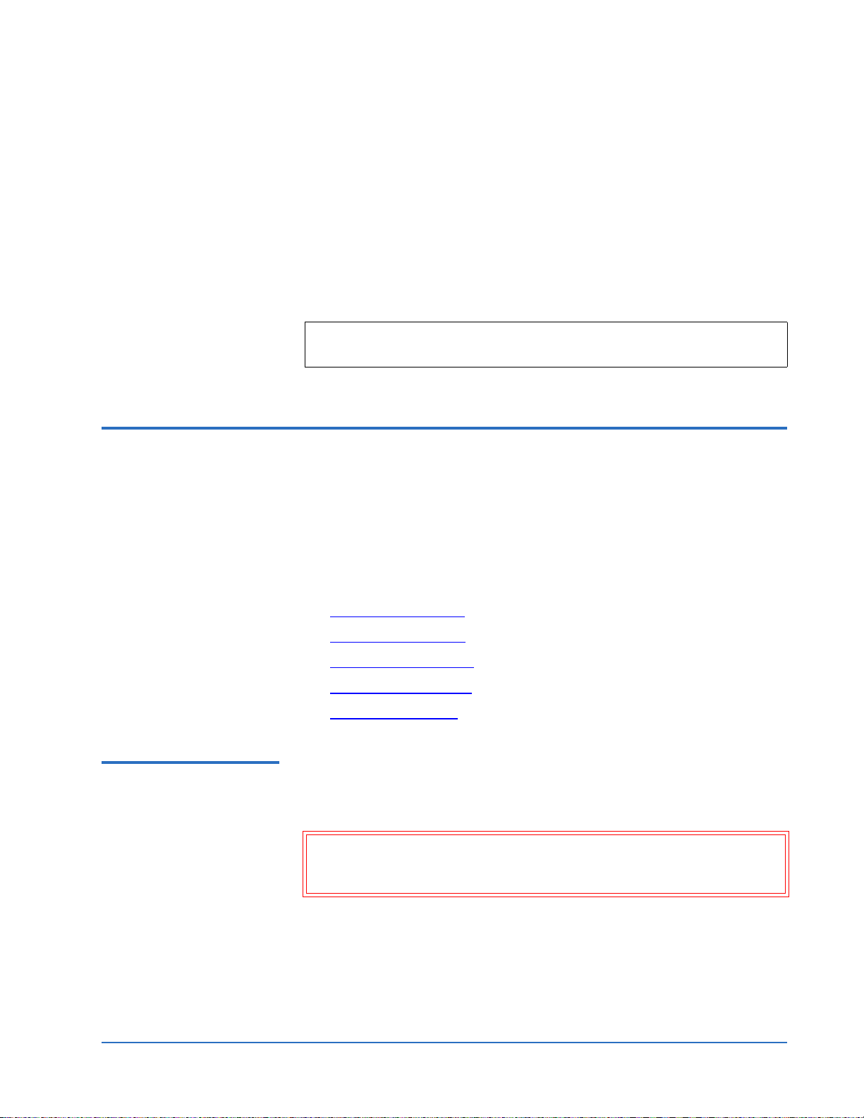
Unboxing the Library 0 To unbox the library:
1 Check the packing list and verify that all components have been received.
Note: If any part is missing or damaged (look for scuffs on the
antistatic bag), contact your authorized reseller.
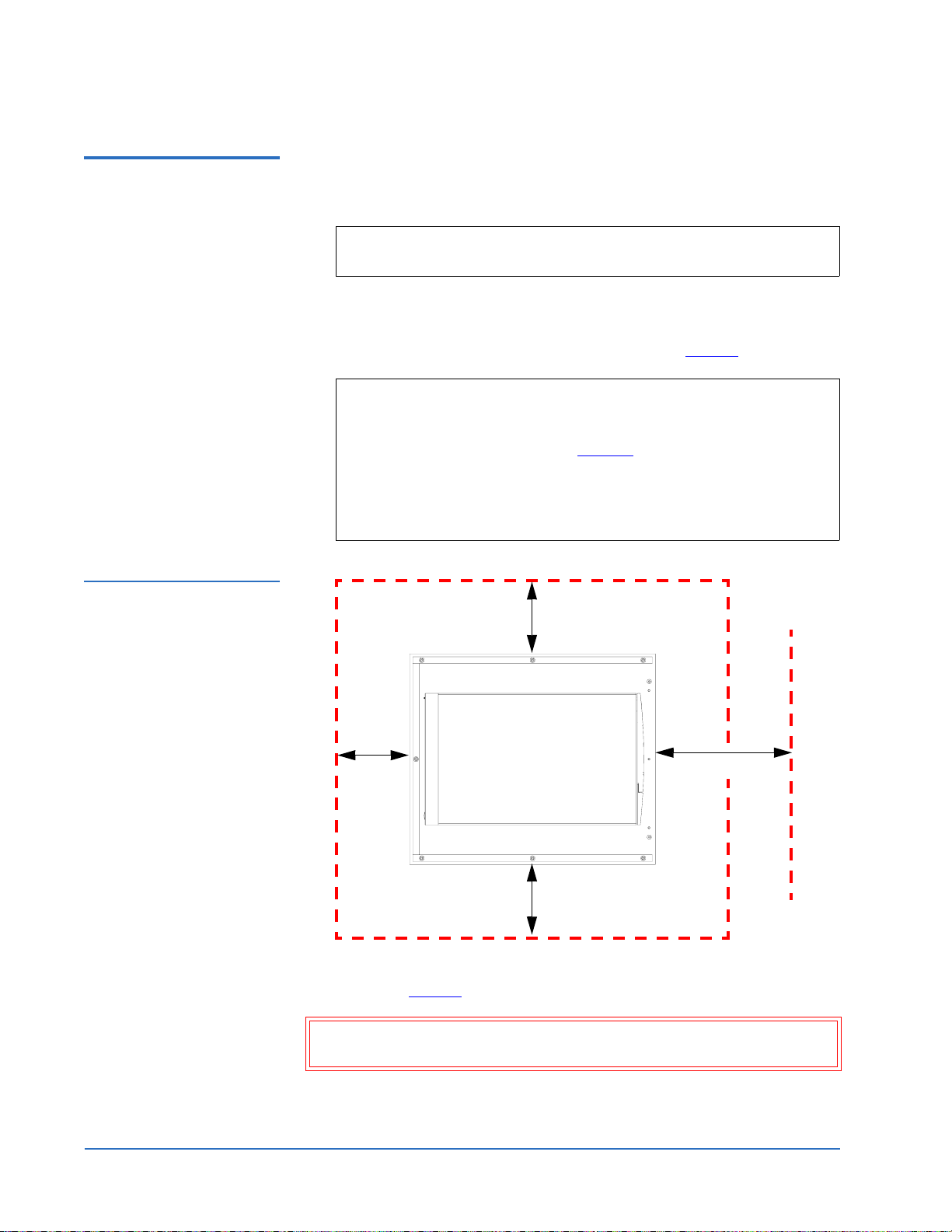
2 Choose the unloading side. The PX720 may be unloaded from only the
right side of the pallet.
Figure 5 Minimum Floor
Space Requirements—
Uncrating Site
3 Verify the minimum floor space requirements (see figure 5
).
Note: Uncrating the library requires a minimum of 3 feet (91 cm) on
all sides. For the side being used for the ramp, uncrating the
library requires an additional 7 feet (2.13 m) for a total of 10
feet (3.05 m) on that side. Figure 5
shows the minimum floor
space required by the PX720 at its uncrating site. The
minimum height required for unpacking the PX720 is 85
inches (2.16 meters). The crate occupies a footprint of 48 x 56
in. (122 x 142 cm).
3 ft. (91 cm)
Ramp side
3 ft.
(91 cm)
7 ft. (2.13 m)
4 Cut the two steel bands that secure the library and packing material to the
pallet (see figure 6
).
Warning: The steel bands are under tension and will snap away when
cut. Wear safety goggles when cutting the steel bands.
8 Unpacking the Library
Cabinet
front
3 ft. (91 cm)
Page 9
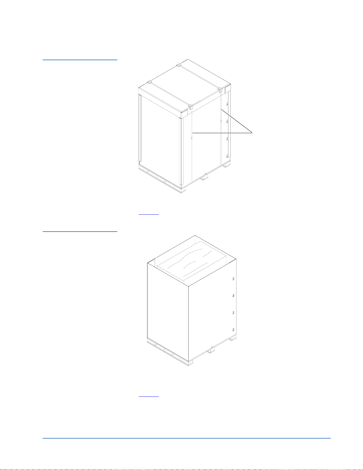
Figure 6 Removing the
Steel Bands
Quantum PX720 Unpacking and Installation Instructions
Document 6444602-03 A01
August 2004
Steel bands
Figure 7 Removing the
Box Top Cover
5 Lift the cardboard box top cover straight up and off of the pallet (see
figure 7
).
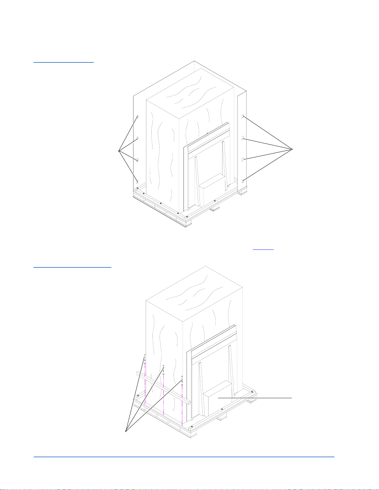
6 Remove the eight cardboard box retaining clips to their open position and
unwrap the two pieces of the cardboard box from the library (see
figure 8
).
Unpacking the Library 9
Page 10
Quantum PX720 Unpacking and Installation Instructions
Document 6444602-03 A01
August 2004
Figure 8 Removing the
Cardboard Box
Figure 9 Removing the
Front Pallet Rail
Retaining
clips
Retaining clips
7 Remove the 3-3/8 in. hex head bolts, lock washers, and flat washers from
the front rail of the pallet and set aside (see figure 9
).
Bolts
10 Unpacking the Library
Accessory kit
Page 11
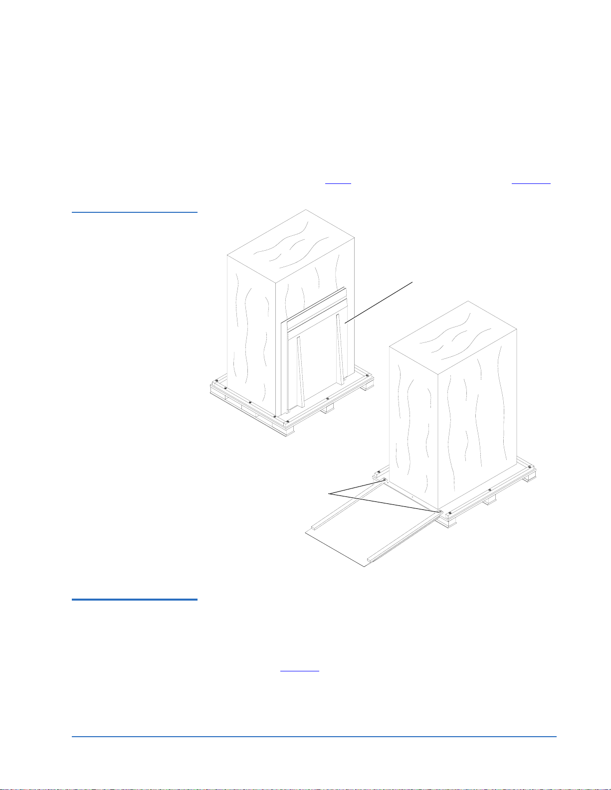
Figure 10 Lowering the
Ramp
Quantum PX720 Unpacking and Installation Instructions
Document 6444602-03 A01
August 2004
8 Remove the front rail from the pallet.
9 Remove the accessory kit from the pallet and place it at a location to be
accessed later.
10 Cut the tape securing the ramp against the library.
11 Use two of the hex 3-3/8 in. hex head bolts, lock washers, and flat
washers removed in step 7
to secure the ramp to the pallet (see figure 10).
Ramp
Hex head bolts
Positioning the Library0 To position the library:
1 Map out a route to the installation site (see the Quantum PX720 Pre-
Installation Site Survey Instructions).
2 Remove the four restraining bolts securing the PX720 to the shipping
pallet (see figure 11
Unpacking the Library 11
) using a 3/4 in open-end wrench.
Page 12

Quantum PX720 Unpacking and Installation Instructions
Document 6444602-03 A01
August 2004
Figure 11 Removing the
Restraining Bolts
Figure 12 Raising the
Leveling Feet
Bolts
Bolts
3 Raise the leveling feet (see figure 12).
Leveling feet
in raised position
4 Inspect the library for any damage that may have occurred during
shipment.
12 Unpacking the Library
Page 13

Figure 13 Rolling the
Library Down the Ramp
Quantum PX720 Unpacking and Installation Instructions
Document 6444602-03 A01
August 2004
5 Carefully roll the library down the ramp (see figure 13).
Warning: The Quantum PX720 with 20 tape drives weighs 1350
pounds (612 kg). Two people are required to move and
install the library.
6 Guide the library to its final installation site.
7 After the library is in its final position, remove the antistatic bag covering
the library.
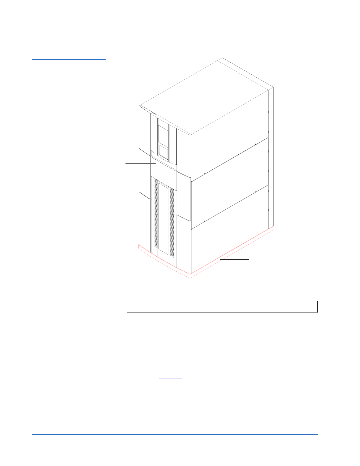
Unpacking the Library 0 To unpack the library:
1 Remove the base shipping foam covering the bottom edge of the library
(see figure 14
).
Unpacking the Library 13
Page 14
Quantum PX720 Unpacking and Installation Instructions
Document 6444602-03 A01
August 2004
Figure 14 Removing the
Base Shipping Foam
Service
tray
Base shipping foam
2 Unlock and open the library doors (front and back):
Note: The front door lock is located behind the service tray.
a Using the key from the accessories kit, unlock each door.
b Lift each door handle straight up and then turn the handle to unlatch
each door.
c Gently pull on each door handle to open the door.
3 From the front of the library, remove the foam from the Y-axis cover
plate, from the left front door, and also from the back door frame and
discard (see figure 15
).
14 Unpacking the Library
Page 15

Figure 15 Removing the
Shipping Foam
Quantum PX720 Unpacking and Installation Instructions
Document 6444602-03 A01
August 2004
Foam
Foam
Back of library Front of library
4 Using the power cables from the accessory kit, connect the library to a
grounded power source (see figure 16
).
Note: Do not turn on the library.
Unpacking the Library 15
Page 16

Quantum PX720 Unpacking and Installation Instructions
Document 6444602-03 A01
August 2004
Figure 16 Library Power
Connections
Power connectors
5 Remove the internal library frame restraints by (see figure 17):
a Removing four 1/4 in. hex nuts securing the two pieces of the
restraint with a 7/16 in. wrench or socket.
b Removing the two Allen head screws securing the restraint to the top
and bottom of the library frame with a 3/16 in. Allen wrench.
c Collapse the internal frame restraints and store with the shipping
materials (see Storing the Shipping Materials
Note: Do NOT discard the internal frame restraints or other shipping
materials. These materials may be needed to ship the library at
a later time.
16 Unpacking the Library
on page 22).
Page 17

Figure 17 Removing the
Internal Library Frame
Restraint
Quantum PX720 Unpacking and Installation Instructions
Document 6444602-03 A01
August 2004
Bolt
Bolt
Hex nuts
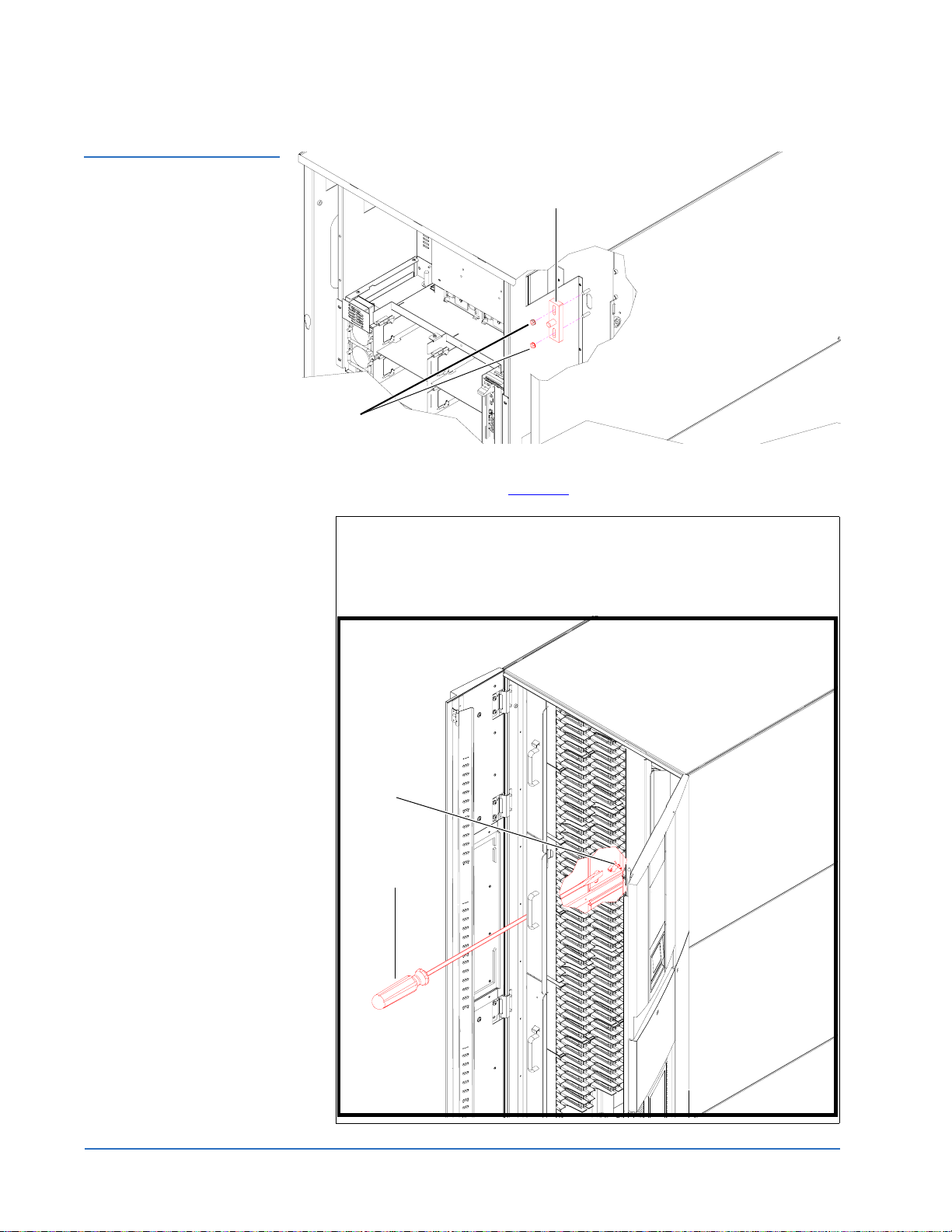
6 From the front of the library, remove the two shipping restraints (vertical
has 4 screws and robot has 7 screws) securing the robot with a PHILLIPS
screwdriver (see figure 18
).
Unpacking the Library 17
Page 18

Quantum PX720 Unpacking and Installation Instructions
Document 6444602-03 A01
August 2004
Figure 18 Removing the
Robot Shipping Restraints
Robot
shipping restraint
Vertical axis
shipping restraint
7 Use the screws removed in step 6, to attach the vertical axis shipping
restraint to the robot shipping restraint (see figure 19
).
8 Store the five spare screws in the robot shipping restraint as shown in
figure 19
.
9 Using the remaining two screws, secure the shipping restraints in the
library as shown in figure 19
.
18 Unpacking the Library
Page 19

Figure 19 Storing the
Shipping Restraints
Quantum PX720 Unpacking and Installation Instructions
Document 6444602-03 A01
August 2004
Shipping restraints
in storage position
Spare
screws
Shipping
restraints
Figure 20 Removing the
Counter Weight Shipping
Restraint
10 From the back of the library, remove the two nuts securing the counter
weight shipping restraint to the back wall with a 7/16 inch wrench (see
figure 20
Nuts
).
Shipping restraint
11 Reverse the counter weight shipping restraint and reinstall on the back
wall of the library using the two nuts previously removed in step 10
figure 21
).
(see
Unpacking the Library 19
Page 20
Quantum PX720 Unpacking and Installation Instructions
Document 6444602-03 A01
August 2004
Figure 21 Storing the
Counter Weight Shipping
Restraint
Nuts
12 Remove the six panel shipping restraints (three on each side) with a 7/16
in. wrench or socket (see figure 22
Shipping restraint
).
Note: To access the lower panel restraints, you must manually trip
the load port latching mechanism to release the load port. The
load port latching mechanism is located between the load port
and the outer skin of the panel (see below). Using the tip of a
screw driver, lift the latch up to release the load port.
Latch
Screwdriver
20 Unpacking the Library
Page 21

Figure 22 Removing the
Panel Shipping Restraints
Load port latching
mechanism
Quantum PX720 Unpacking and Installation Instructions
Document 6444602-03 A01
August 2004
Upper shipping restraint
Upper shipping restraint
Middle shipping restraint
Lower shipping restraint
Panels shown outside of library for clarity
13 Store the panel shipping restraint hardware (three sets on each side) on
Middle shipping restraint
Lower shipping restraint
the lower cabinet frame as shown in figure 23
.
Unpacking the Library 21
Page 22

Quantum PX720 Unpacking and Installation Instructions
Document 6444602-03 A01
August 2004
Figure 23 Panel Shipping
Restraints Storage
Locations
Panel restraint
storage locations
Left storage position shown
Storing the Shipping Materials
0
To store the shipping and packaging materials for future use:
1 Detach the ramp and place on top of the pallet.
2 Fold the shipping bag.
3 Place the shipping bag, foam cap, screws, internal library frame restraint,
and other packaging materials on the pallet.
4 Collapse the cardboard box.
5 Place the cardboard box on top of the packaging materials on the pallet.
6 Secure the pallet, packaging materials, and cardboard box for future use.
Leveling the Library 0 To level the library:
1 Rotate each foot of the library until it makes contact with the floor.
2 Rotate each foot an additional 1/4 turn with the open-end wrench to
begin raising the library.
3 Center a carpenter’s level on the top front edge of the library.
4 Check the gauge on the level. If the front of the library is level, proceed to
step 6
. If it is not level:
a Determine which side of the library is low.
b Adjust the leveling foot on the low side of the library by rotating the
leveling foot with the open-end wrench.
22 Unpacking the Library
Page 23

Quantum PX720 Unpacking and Installation Instructions
5 Repeat step 4 until the front is level.
Document 6444602-03 A01
August 2004
6 Repeat step 3
library.
7 Recheck the level on all top edges.
8 If necessary, repeat step 3
are level.
The unpacking is complete.
and step 4 for the left edge, back edge, and right edge of the
and step 4 until all four top edges of the library
Installing the Quantum PX720 Library 0
Installing the Quantum PX720 library consists of the following steps:
• Cabling the Quantum PX720
• Connecting the Cluster Controller Ethernet Cables
• Cabling a SCSI PX720 Library
• Cabling a Fibre Channel PX720 Library
• Loading the Tape Cartridges
• Initial Configuration
Cabling the Quantum PX720
After the Quantum PX720 is in its final location, the tape drives and robotics
0
controller must be connected to the backup host system(s). The cluster
controllers must also be connected with Ethernet cables. The PX720 supports
both SCSI and Fibre Channel host interfaces.
Refer to the appropriate section for your PX720 installation:
• Connecting the Cluster Controller Ethernet Cables
• Cabling a SCSI PX720 Library
• Cabling a Fibre Channel PX720 Library
Connecting the Cluster Controller Ethernet Cables 0
To connect the Cluster Controller Ethernet cables:
1 Open the back door of the Quantum PX720 to gain access to the tape
drive cluster controllers (see figure 25
2 Refer to table 1
connections.
and figure 24 for the tape drive cluster Ethernet
on page 26).
Installing the Quantum PX720 Library 23
Page 24

Quantum PX720 Unpacking and Installation Instructions
Document 6444602-03 A01
August 2004
Table 1 Cluster Controller
Ethernet Connections
Tape Drive Cluster Cluster Controller Ethernet Connections
Tape Drive Cluster 0 Eth1 - to internal network from the cabinet
controller
Eth2 - not used
Eth3 - to first FC470 if present
Eth4 - to tape drive cluster 1; Eth1
Tape Drive Cluster 1 Eth1 - to tape drive cluster 0; Eth4
Eth2 - not used
Eth3 - to second FC470 if present
Eth4 - to tape drive cluster 2; Eth1
Tape Drive Cluster 2 Eth1 - to tape drive cluster 1; Eth 4
Eth2 - not used
Eth3 - to third FC470 if present
Eth4 - to tape drive cluster 3; Eth1
Tape Drive Cluster 3 Eth1 - to tape drive cluster 2; Eth4
Eth2 - not used
Eth3 - to fourth FC470 if present
Eth4 - to tape drive cluster 4; Eth1
Tape Drive Cluster 4 Eth1 - to tape drive cluster 3; Eth4
Eth2 - not used
Eth3 - to fifth FC470 if present
Eth4 - not used
24 Installing the Quantum PX720 Library
Page 25

Figure 24 Cluster Controller
Ethernet Connections
Quantum PX720 Unpacking and Installation Instructions
Document 6444602-03 A01
August 2004
Tape drive
cluster 0
Tape drive
cluster 1
Tape drive
cluster 2
Cluster controller
2
I
C
Eth 1
Eth 2
Eth 3
Eth 4
Tape drive
cluster 3
Tape drive
cluster 4
Installing the Quantum PX720 Library 25
Page 26

Quantum PX720 Unpacking and Installation Instructions
Document 6444602-03 A01
August 2004
Cabling a SCSI PX720 Library 0
To cable a SCSI Quantum PX720:
1 Open the back door of the Quantum PX720 to gain access to the tape
drives and robotics controller (see figure 25
).
Figure 25 Tape Drives and
Robotics Controller
Tape drive numbering
Drive B (1) Drive A (0)
Drive C (2)Drive D (3)
Cluster 0, tape drives 0 through 3
Cluster 1, tape drives 4 through 7
Cluster 2, tape drives 8 through 11
Cluster 3, tape drives 12 through 15
Cluster 4, tape drives 16 through 19
2 Route a SCSI cable up through the base of the library on the right-hand
side and connect the host computer to the robotics controller (see
figure 25
).
Note: It is also possible to connect the SCSI robotics controller along
with the first drive in cluster 0.
26 Installing the Quantum PX720 Library
SCSI HBA
Page 27

Figure 26 Connecting the
Tape Drives
Quantum PX720 Unpacking and Installation Instructions
Document 6444602-03 A01
August 2004
3 Connect the host computers to the tape drives by routing SCSI cables up
through the base of the library and along the right-hand side of the
cabinet (see figure 26
).
Tech Tip: Start cabling with drive cluster 0 at the top of the library
and work down.
Host computers
Terminators
Cluster with 2 tape drives
per bus
Host computers
Cluster with 1 tape drives
per bus
Terminators
Host computers
Terminators
SCSI cables
Host computers
Note: Make sure that all SCSI cables droop down slightly to ensure
that the back door closes.
4 Route an Ethernet cable up through the base of the library and connect
the front Ethernet port located on the right side of the cabinet controller to
the local network (see figure 27
Installing the Quantum PX720 Library 27
).
Page 28

Quantum PX720 Unpacking and Installation Instructions
Document 6444602-03 A01
August 2004
Figure 27 Connecting the
Library to the Local Area
Network
5 Close the back door.
Service port
Ethernet port
under service tray
Local area
Ethernet port
Cabinet controller enclosure
shown outside for clarity
Cabling a Fibre Channel PX720 Library
Use the following procedure to connect the SCSI jumper cables, terminators,
and Ethernet cables to the tape drive cluster(s) and FC470(s).
• SCSI connectors 0 through 3 on the first FC470 are used to connect to tape
drives 0 through 3 and the library SCSI HBA.
• SCSI connectors 0 through 3 on the second FC470 are used to connect to
tape drives 4 through 7, if present.
• SCSI connectors 0 through 3 on the third FC470 are used to connect tape
drives 8 through 11.
• SCSI connectors 0 through 3 on the fourth FC470 are used to connect tape
drives 12 through 15.
• SCSI connectors 0 through 3 on the fifth FC470 are used to connect tape
drives 16 through 19.
Secure the SCSI cables from the FC470(s) to the card cage in the cable clamp
located on the right-hand side of the card cage. After you have completed the
SCSI connections from the FC470 bridges to the tape drives, close the back
access door on the library.
To cable a FC470 bridge to the tape drive cluster(s):
1 To connect the SCSI cables from the FC470 to the tape drives, see table 2
and figure 28
.
0
2 Route an Ethernet cable up through the base of the library and connect
the front Ethernet port located on the right side of the cabinet controller to
the local network (see figure 27
).
3 Connect an Ethernet cable from each tape drive cluster (E3) to it’s
corresponding FC470.
28 Installing the Quantum PX720 Library
Page 29

Quantum PX720 Unpacking and Installation Instructions
Document 6444602-03 A01
August 2004
4 The SCSI, Ethernet, and Fibre Channel cables must be routed and stacked
in the right-hand clamps correctly so the back door will close. Route the
cables down through the cable channel on the right-hand side of the
library. Refer to figure 29
and figure 30 for cable diagrams illustrating the
correct cable placement.
Caution: Use care when handling the fibre optic cables. Do not
crimp or bend the cables.
Table 2 Cabling a FC470
Bridge to the Tape Drives
T ape Drive Connection FC470 Connections/ Tape Drive
Termination
Tape drive 0, upper port Port 0 on first FC470
Tape drive 0, lower port Library SCSI HBA
Tape drive 1, upper port Port 1 on first FC470
Tape drive 1, lower port Terminator
Tape drive 2, upper port Port 2 on first FC470
Tape drive 2, lower port Terminator
Tape drive 3, upper port Port 3 on first FC470
Tape drive 3, lower port Terminator
Tape drive 4, upper port Port 0 on second FC470
Tape drive 4, lower port Terminator
Tape drive 5, upper port Port 1 on second FC470
Tape drive 5, lower port Terminator
Tape drive 6, upper port Port 2 on second FC470
Tape drive 6, lower port Terminator
Tape drive 7, upper port Port 3 on second FC470
Tape drive 7, lower port Terminator
Tape drive 8, upper port Port 0 on third FC470
Tape drive 8, lower port Terminator
Tape drive 9, upper port Port 1 on third FC470
Tape drive 9, lower port Terminator
Installing the Quantum PX720 Library 29
Page 30

Quantum PX720 Unpacking and Installation Instructions
Document 6444602-03 A01
August 2004
T ape Drive Connection FC470 Connections/ Tape Drive
Tape drive 10, upper port Port 2 on third FC470
Tape drive 10, lower port Terminator
Tape drive 11, upper port Port 3 on third FC470
Tape drive 11, lower port Terminator
Tape drive 12, upper port Port 0 on fourth FC470
Tape drive 12, lower port Terminator
Tape drive 13, upper port Port 1 on fourth FC470
Tape drive 13, lower port Terminator
Tape drive 14, upper port Port 2 on fourth FC470
Termination
Tape drive 14, lower port Terminator
Tape drive 15, upper port Port 3 on fourth FC470
Tape drive 15, lower port Terminator
Tape drive 16, upper port Port 0 on fifth FC470
Tape drive 16, lower port Terminator
Tape drive 17, upper port Port 1 on fifth FC470
Tape drive 17, lower port Terminator
Tape drive 18, upper port Port 2 on fifth FC470
Tape drive 18, lower port Terminator
Tape drive 19, upper port Port 3 on fifth FC470
Tape drive 19, lower port Terminator
30 Installing the Quantum PX720 Library
Page 31

Quantum PX720 Unpacking and Installation Instructions
Document 6444602-03 A01
August 2004
Figure 28 PX720
Interconnect (20 drives)
Eth3 on drive cluster 1
Eth3 on drive cluster 2
FC470 4
SCSI 0
SCSI 2
SCSI 1
SCSI 3
FC470 2
FC470 3
SCSI 0
SCSI 2
SCSI 1
SCSI 3
Eth3 on drive cluster 3
SCSI 3
FC470 1
SCSI 2
SCSI 1
SCSI 3
SCSI 0
SCSI 0
SCSI 2
SCSI 1
Tape drive cluster 0
Tape drive cluster 1
Tape drive cluster 2
Eth3 on drive cluster 0
Tape drive 1
Tape drive 3
Tape drive 5
Tape drive 7
Tape drive 9
Tape drive 11
Library SCSI HBA
Tape drive 0
Tape drive 2
Tape drive 4
Tape drive 6
Tape drive 8
Tape drive 10
FC470 5
SCSI 3
Terminator
SCSI 2
SCSI 0
SCSI 1
Eth3 on drive cluster 4
Tape drive cluster 3
Tape drive cluster 4
Tape drive 13
Tape drive 15
Tape drive 17
Tape drive 19
Tape drive 12
Tape drive 14
Tape drive 16
Tape drive 18
Installing the Quantum PX720 Library 31
Page 32

Quantum PX720 Unpacking and Installation Instructions
Document 6444602-03 A01
August 2004
Figure 29 Securing the
SCSI, Ethernet, and Fibre
Channel Cables
SCSI (4 ports)
Fibre Channel (2 ports)
Ethernet (1 port)
SCSI cables route
Ethernet and Fibre Channel
cables route
Cable channel
Excess SCSI cable
32 Installing the Quantum PX720 Library
Page 33

Figure 30 FC470 Cable
Connections Maximum
Drive Configuration
Quantum PX720 Unpacking and Installation Instructions
Document 6444602-03 A01
August 2004
Installing the Quantum PX720 Library 33
Page 34
Quantum PX720 Unpacking and Installation Instructions
Document 6444602-03 A01
August 2004
Refer to the Quantum PX720 FC470 Upgrade Instructions (PN 6444614) for
instructions on configuring the FC470 Fibre Channel bridge.
Loading the Tape Cartridges
0
Before operating the library, load the appropriate tape cartridges (LTO or
SDLT) into the library starting with the left-hand panels (refer to the Quantum
PX720 User’s Guide PN 6444601 for more information on tape cartridges).
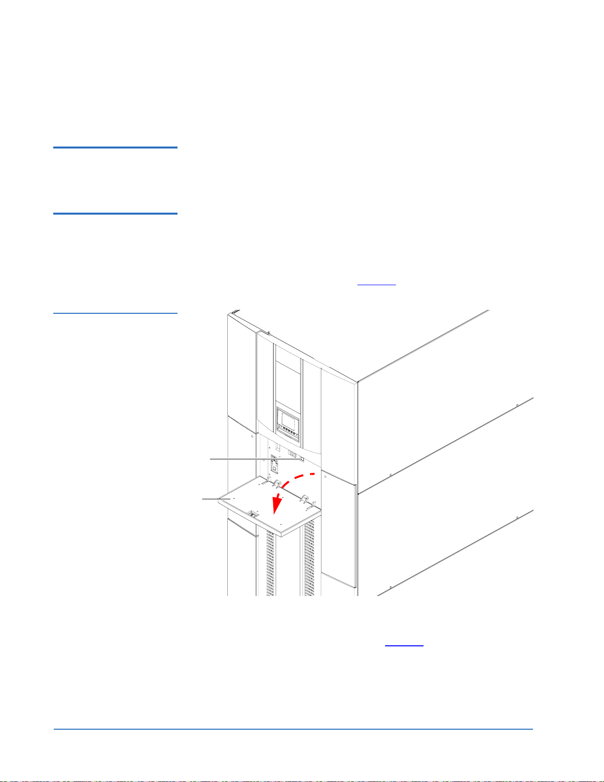
Initial Configuration 0 The Quantum PX720 must be initially configured with an IP address before
the remote management software is available.
To configure the Quantum PX720 IP address:
1 Press on the top of the service tray to tip it down and press the power
button to turn on the library (see figure 31
Figure 31 Turning on the
Library
).
Power button
Service tray
2 When the library completes the boot up sequence and the OCP is active,
press
Menu from the Home screen.
The OCP displays the
34 Installing the Quantum PX720 Library
Menu screen (see figure 32):
Page 35

Figure 32 Menu Screen
Quantum PX720 Unpacking and Installation Instructions
Document 6444602-03 A01
August 2004
Select
Figure 33 Password
Screen
3 From the Menu screen, use the up and down arrows to highlight Setup
and press
4 The library prompts you for your password (see figure 33
Select.
).
5 Enter the 6 digit password.
The password is accepted after the sixth digit is entered.
Note: The default password is 001122.
The
Setup screen displays (see figure 34):
Installing the Quantum PX720 Library 35
Page 36

Quantum PX720 Unpacking and Installation Instructions
Document 6444602-03 A01
August 2004
Figure 34 Setup Screen
Back Select
The Setup screen displays the following information:
• IP Address (requires cabinet reboot)
•IP Subnet Mask
•IP Gateway
• DHCP (default enabled)
• Change Password
• Restore Factory Settings
•Drive Autoclean
• Configured Drives
• Configured Slots
•Left Load Port (16)
• Right Load Port (32)
•Service Mode
6 To edit the setup information, use the up and down arrows to highlight
the section and press
Select.
• To set the IP address, subnet mask, and gateway, use the up and
down arrows to select the appropriate number and press
Select to
accept.
• To enable/disable DHCP, use the up and down arrows to toggle
between enable/disable. Press
library is not connected to a network which uses a DHCP server to
assign IP addresses, disable this function.
36 Installing the Quantum PX720 Library
Select to accept the setting. If your
Page 37

Quantum PX720 Unpacking and Installation Instructions
Document 6444602-03 A01
August 2004
• To change the password, use the up and down arrows to select
Change Password and press
Select. To change the password, enter a
6-digit password using the numbers provided on the OCP. Press
Select to accept the new password. When prompted, re-enter the
password to confirm.
• To enable autoclean, use the up and down arrows to select Autoclean
and press
Select.
• To enable the left load port, use the up and down arrows to select Left
Load Port (16) and press
Select.
• To enable the right load port, use the up and down arrows to select
Right Load Port (32) and press
Select.
7 When you are finished viewing/editing the setup information, press
Back twice to return to the Home screen.
8 From the
Home screen, press Ops to enter the operations screen.
9 Before the network information can become active, the cabinet must
reboot. To reboot the cabinet, use the up and down arrows to highlight
the cabinet and press
Select.
10 Use the up and down arrows to select the reboot option and press
The library reboots.
Select.
Installing the Quantum PX720 Library 37
Page 38

Quantum PX720 Unpacking and Installation Instructions
Document 6444602-03 A01
August 2004
38 Installing the Quantum PX720 Library
 Loading...