

Page 1

Quantum ATL P4000 and
ATL P7000 Prism FC470
User’s Guide Addendum
Introduction 3
Fibre Channel Description ...........................................................................3
Prism FC470 Router Operation ...................................................................3
Supported Fibre Channel Host Bus Adapters and Switches ..................3
Supported Backup Applications .................................................................4
Quantum Customer Support.......................................................................5
FC470 Overview 5
FC470 Web Interface 7
FC470 Menu Items.........................................................................................8
Accessing the FC470 Web Pages .................................................................8
Home Page .....................................................................................................9
System Page..................................................................................................10
Ports Page .....................................................................................................16
Discovery Page ............................................................................................21
Mapping Page..............................................................................................22
Statistics Page...............................................................................................25
Utilities Page ................................................................................................26
Trace Settings Configuration .....................................................................28
Current, Previous, and Last Assert Trace Displays................................29
Clear Current and Assert Traces...............................................................30
Document 6331190-01, Ver. 1, Rel. 1, July 2003 1
Page 2

Quantum ATL P4000 and ATL P7000 Prism FC470 User’s Guide Addendum
Document 6331190-01, Ver. 1, Rel. 1
July 2003
Event Log Configuration ........................................................................... 31
Event Log Display....................................................................................... 32
Clear Event Log........................................................................................... 32
Report Menu................................................................................................ 33
Reboot Option .............................................................................................33
Troubleshooting 34
LED Indicators............................................................................................. 34
Basic Troubleshooting................................................................................ 35
2 6207947-04fN 20
Page 3

Quantum ATL P4000 and ATL P7000 Prism FC470 User’s Guide Addendum
Document 6331190-01, Ver. 1, Rel. 1
July 2003
Introduction 0
The Quantum ATL P4000/P7000 Series automated tape libraries are
controlled by a host computer via a SCSI differential bus using the
SCSI-2 medium changer command set. There is also an RS-232
diagnostic port interface.
The P4000/P7000 Prism Architecture™ allows for easy conversion
from the SCSI host interface to a Fibre Channel host interface. This
document describes upgrading a standard P4000/P7000 equipped
with a SCSI host interface to a Fibre Channel host interface using a
Prism FC470 Upgrade kit.
Fibre Channel Description
Prism FC470 Router Operation
Fibre Channel is a serial data transfer architecture for use with
0
computers and mass storage devices that is rapidly emerging to
challenge SCSI as the interface of choice for host-to-storage
applications.
Fibre Channel advantages include:
• Connection distances with the Quantum ATL FC470 option up to
500 meters
• 2 GB/Sec data transfer rates
• Supports up to 126 devices in a loop mode
• Supports 24-bit addressing for over 16 million devices in point-topoint mode or fabric, when using a Fibre Channel switch or
multiple Fibre Channel switches.
• Operating system independence
• Interconnect flexibility
Once a Prism FC470 Router option is installed and tested, the library
0
operates exactly as a P4000/P7000 with a SCSI host interface.
Operation of the library via the graphical user interface (GUI) is
unchanged.
Supported Fibre Channel Host Bus Adapters and Switches
The following tables provide a list of supported Fibre Channel host
bus adapters (HBAs) and switches that have been tested at the time of
0
this printing. For an updated list of supported Fibre Channel HBAs
and switches, please see www.quantum.com
Introduction 3
.
Page 4

Quantum ATL P4000 and ATL P7000 Prism FC470 User’s Guide Addendum
Document 6331190-01, Ver. 1, Rel. 1
July 2003
Table 1 Supported Fibre
Channel HBAs
Table 2 Supported Fibre
Channel Switches
Manufacturer Model # Minimum Driver Level
Qlogic 2100, 2200,
23xx
Must have QLDriver installed on
host computer. See manufacturer’s
website for latest driver
information.
Emulex LP8K, LP9K See manufacturer’s website for
latest driver information.
JNI 1663, 6410,
65xx
Sun x6749a,
x6757a,
See manufacturer’s website for
latest driver information.
See manufacturer’s website for
latest driver information.
x6767a,
x6768a
Manufacturer Model Name/Number
Brocade Silkworm
McData Connectrix
Supported Backup Applications
Table 3 Supported
Backup Applications
SANbox and SANbox II 8/16
The following table lists the backup applications tested at the time of
0
this printing. For an updated list of supported backup applications,
please see www.quantum.com
Software Developer Application Version
Veritas NetBackup 3.4.1, 4.5 and later
Backup Exec 8.6 and later
Computer
Associates
Legato Networker 5.5, 6.x, 7.0 and later
HP Data Protector Omniback 4.x
BrightStor Enterprise 10.0 and later
ARCServe 6.61, 7.0 and later
.
4 Introduction
Page 5

Quantum ATL P4000 and ATL P7000 Prism FC470 User’s Guide Addendum
Document 6331190-01, Ver. 1, Rel. 1
July 2003
Quantum Customer Support
The Quantum Customer Support Department provides a 24-hour help
0
desk that can be reached at:
North/South America: (949) 725-2100 or
(800) 284-5101
Asia/Pacific Rim: (International Code)
+61 7 3862 4834
Europe/Middle East/Africa: (International Code)
+44 (0) 1256 848748
Send faxes for the Customer Support Department to:
North/South America: (949) 725-2176
Asia/Pacific Rim: (International Code)
+61 7 3862 4677
Europe/Middle East/Africa: (International Code)
+44 (0) 1256 848777
To contact the Customer Support Department use the following web/
E-mail addresses:
North/South America: www.quantum.com/askaquestion
Asia/Pacific Rim:
apachelp@quantum.com
Europe/Middle East/Africa: eurohelp@quantum.com
FC470 Overview 0
The FC470 provides a bridge between a Fibre Channel host and the
SCSI tape drives within a library. Figure 1
Channel bridge and feature locations.
shows the FC470 Fibre
FC470 Overview 5
Page 6

Quantum ATL P4000 and ATL P7000 Prism FC470 User’s Guide Addendum
Document 6331190-01, Ver. 1, Rel. 1
July 2003
Figure 1 FC470 Overview
SCSI ports
Fibre ports
RJ-45 port
SCSI Ports 0
The FC470 contains four SCSI ports or buses (port 0, port 1, port 2, and
port 3). When the SCSI port (bus) is connected to a tape drive, the
corresponding LED is lit indicating activity on the SCSI bus.
Fibre Channel Ports 0
The FC470 contains two Fibre Channel ports (port 0 and port 1). Each
port has two corresponding LEDs. The top LED indicates activity on
the Fibre Channel port and the bottom LED indicates a valid Fibre
Channel link on the port.
Ethernet Port 0
The FC470 contains one Ethernet port which is used for remote
configuration and bridge management. The port has two
corresponding LEDs. The top LED indicates activity on the port and
the bottom LED indicates a valid Ethernet link.
Serial Port 0
The FC470 contains one serial port which is used to access the serial
interface and locally manage or configure the bridge.
Power Indicator 0
The FC470 contains one power LED which indicates two power states
on the bridge. If the LED is green, the bridge is powered on. If the LED
is yellow, the bridge is in the process of performing a “Power-On-SelfTest” or a the bridge has a processor problem.
6 FC470 Overview
Page 7

Quantum ATL P4000 and ATL P7000 Prism FC470 User’s Guide Addendum
Document 6331190-01, Ver. 1, Rel. 1
July 2003
Reset Button 0
The FC470 contains a reset button that is used to force a manual reboot
of the bridge. A pen or other small object must be used to access the
reset button. You can also reboot the FC470 from the web interface.
Caution: Resetting the FC470 during a backup/restore job can
result in a disruption of that process and loss of data.
Ensure all data transfer jobs have completed before
resetting the FC470.
FC470 Web Interface 0
The FC470 utilizes a web-based interface which allows you to
configure and manage the bridge from a remote workstation on the
same network. The FC470 is managed through the following web
pages (accessible using Internet browser software installed on the host
computer):
• Home Page
contains status information, including a physical
image of the FC470.
• System Page
allows you to configure standard system
components.
• Ports Page
allows you to configure both the SCSI and Fibre
Channel ports
• Discovery Page
allows you to display connected devices and
discover new devices
• Mapping Page
• Statistics Page
• Utilities Page
allows you to display and configure route mapping
displays the FC470 statistics
allows you to access FTP utilities and trace
information
• Report Menu
• Reboot Option
displays the consolidated view of all FC470 systems
allows you to remotely reboot the FC470
The FC470 supports the following web browsers:
• Microsoft Internet Explorer 5.5 or later
You can download this software from
http://www.microsoft.com.
• Netscape Navigator 6.2 or later
You can download this software from
http://www.netscape.com.
FC470 Web Interface 7
Page 8
Quantum ATL P4000 and ATL P7000 Prism FC470 User’s Guide Addendum
Document 6331190-01, Ver. 1, Rel. 1
July 2003
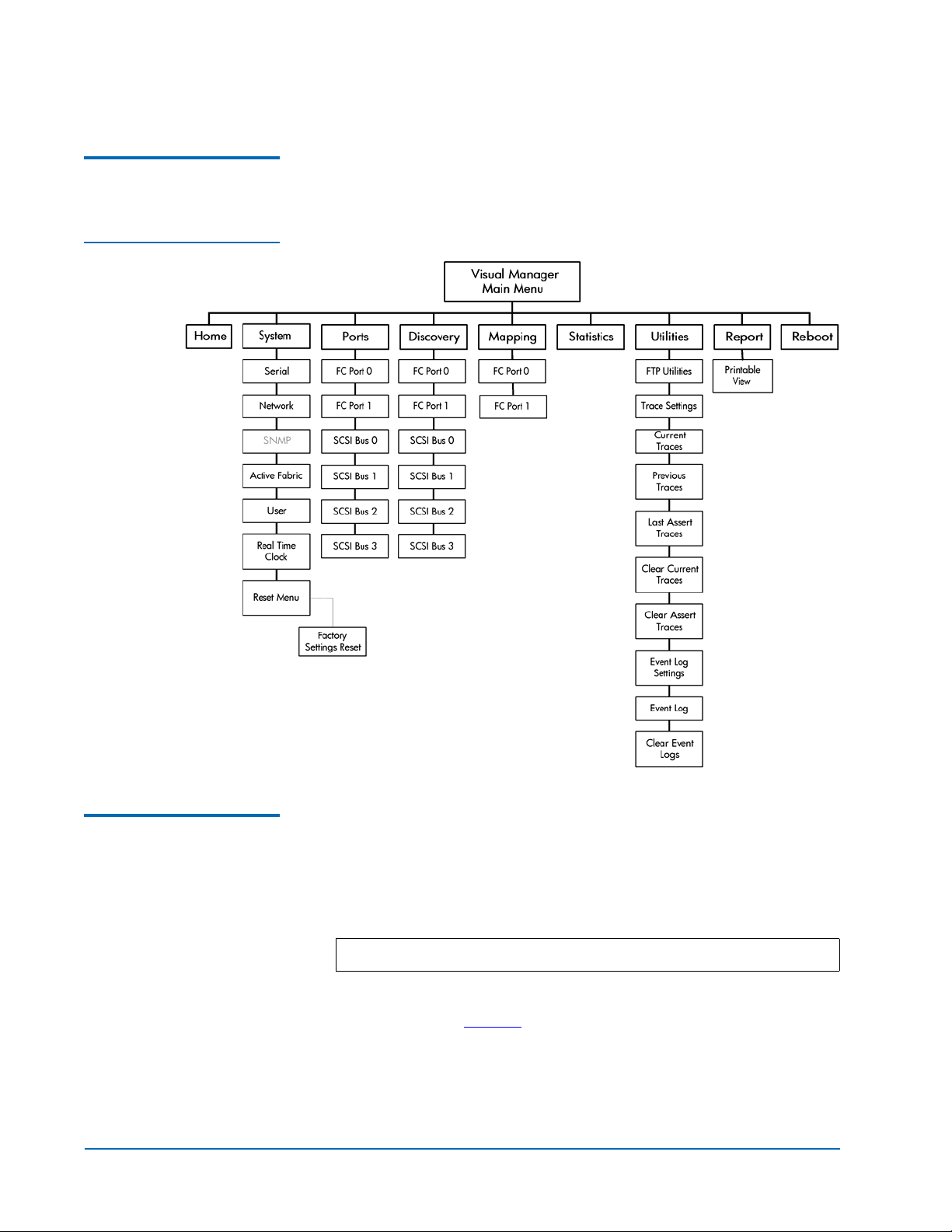
FC470 Menu Items 0
Figure 2 FC470 Menu
Tree
The following figure depicts the menu items available from the FC470
Web Pages.
Accessing the FC470 Web Pages
0
To access the FC470 web pages:
1 On the host computer, open the internet browser software.
In the
Address field, type http://IPaddress/ where IP address is the
IP address for the FC470.
Note: The default IP address is 1.1.1.1
The FC470
Home page is displayed, showing FC470 status
information (see figure 3
who knows the IP address.
8 FC470 Web Interface
). The home page is accessible to anyone
Page 9
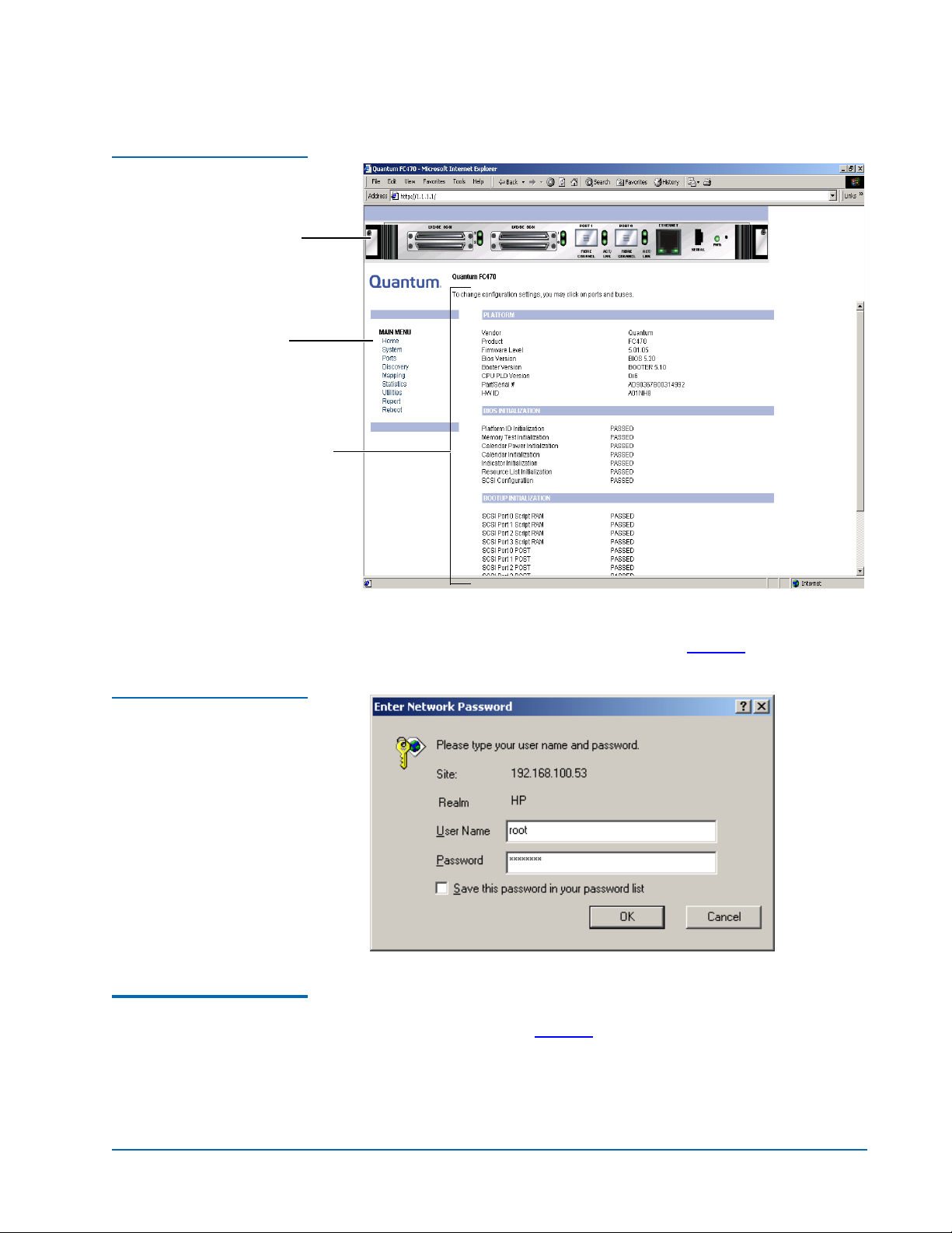
Figure 3 Home Page
FC470 bridge
Main menu
Status information
Quantum ATL P4000 and ATL P7000 Prism FC470 User’s Guide Addendum
Document 6331190-01, Ver. 1, Rel. 1
July 2003
Figure 4 Password Dialog
Home Page 0
2 Select a menu option to access menus and screens.
Password dialog box is displayed (see figure 4).
The
The first page that displays when you access the FC470 web pages is
the FC470
Home page (see figure 3). This page includes information on
the FC470 status as follows:
• Current platform information
• Current bios initialization information
FC470 Web Interface 9
Page 10

Quantum ATL P4000 and ATL P7000 Prism FC470 User’s Guide Addendum
Document 6331190-01, Ver. 1, Rel. 1
July 2003
• Current bootup initialization information
The
Home page is divided into three distinct sections:
• FC470 bridge - The FC470 image is interactive, allowing quick
access to configuration menus:
• To display current settings and status for a port, click the
corresponding port shown on the FC470 image.
• To open a menu for making changes to the configuration for
that particular port or bus, click the desired Fibre Channel port
or SCSI port.
System Page 0
• To open the
Network Configuration page, click the Ethernet port
• Main menu
• Bridge status information
The banner frame displays the corporate logo and product name. The
main menu displays a list of the FC470 web pages. To view a page,
click its corresponding link. The management frame displays the page
you selected.
The
System page is used to view and configure serial, network, trap,
active fabric, clock, and power supply components.
To access the
1 Click System from the Main menu on the Home page.
The
System page:
System page displays (see figure 5):
10 FC470 Web Interface
Page 11
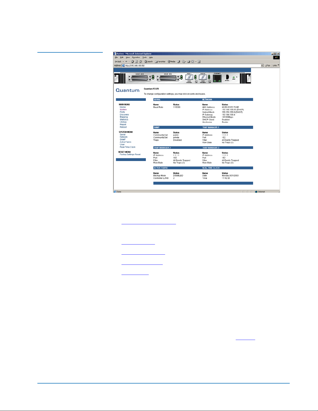
Figure 5 System Page
Quantum ATL P4000 and ATL P7000 Prism FC470 User’s Guide Addendum
Document 6331190-01, Ver. 1, Rel. 1
July 2003
.
The System page allows you to configure:
• Serial port (Quantum Field Service Only)
• Network Information
• SNMP (currently not supported)
• Active Fabric
• User Information
• Real Time Clock
• Reset Page
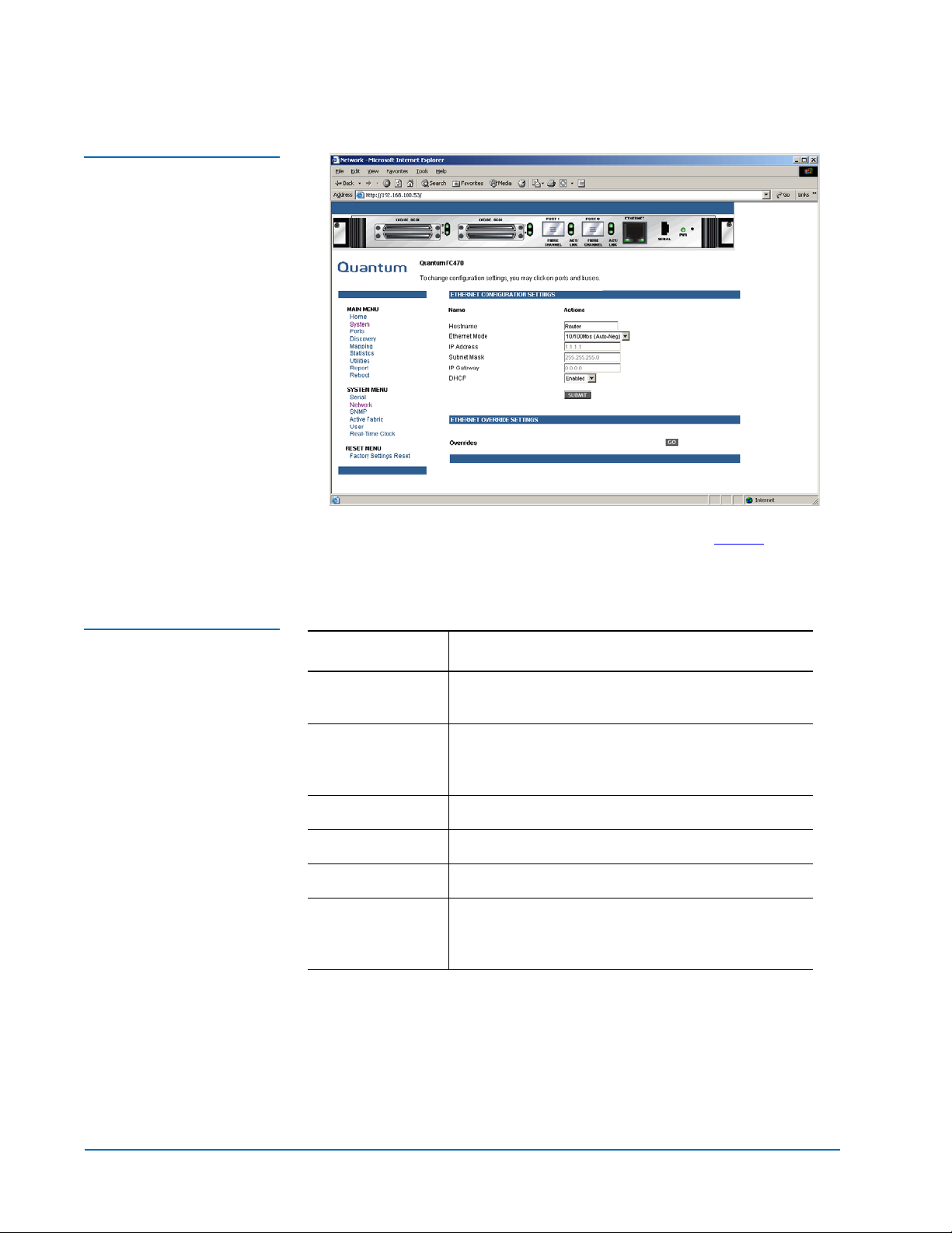
Network Information 0
The
Network Information page allows you to configure network
settings for the FC470.
To access the
1 Click Network in the System menu.
The Network Information page displays (see figure 6
Network Information page:
):
FC470 Web Interface 11
Page 12
Quantum ATL P4000 and ATL P7000 Prism FC470 User’s Guide Addendum
Document 6331190-01, Ver. 1, Rel. 1
July 2003
Figure 6 Network
Information Page
Table 4 Network
Configuration Fields
2 Edit the configuration information as desired (see table 4 for a
description of the fields) and click
Submit to accept any new
information.
Field Description
Hostname View or set the hostname for the FC470 (for
example, the DNS name)
Ethernet Mode View or set the Ethernet port speed (10Mps,
100Mps half duplex, 100Mps full duplex, 10/100
auto negotiate
IP Address View or set the IP address for the FC470
Subnet Mask View or set the subnet mask for the FC470
IP Gateway View or set the IP gateway for the FC470
DHCP Enable or disable DHCP support. When enabled,
the FC470 requests a dynamic IP address form a
DHCP server on the Ethernet network.
The FC470 will not use the new basic configuration until it has been
rebooted.
Active Fabric 0
The
Active Fabric page allows you to configure active fabric options on
the FC470.
12 FC470 Web Interface
Page 13

Figure 7 Active Fabric
Page
Quantum ATL P4000 and ATL P7000 Prism FC470 User’s Guide Addendum
To access the Active Fabric page:
1 Click Active Fabric in the System menu.
Active Fabric page displays (see figure 7):
The
Document 6331190-01, Ver. 1, Rel. 1
July 2003
Table 5 Active Fabric
Fields
2 Edit the active fabric information as desired (see table 5 for a
description of the fields) and click
Submit to accept any new
information.
Field Description
Number of
Controller LUNS
Controller LUNS
in Auto
Assigned Map
Go
User Information 0
The
User Information page allows you to configure FC470 security.
To access the
User Information page:
1 Click User Information in the System menu.
View or set the number of controller LUNs
reported by the FC470. This number must be in
the range of 0 through 4 (default=0)
View or set the location of LUNs in the Port 0 and
Port 1 map. This setting can be toggled between
first and last (default=last)
User Information page displays (see figure 8).
The
FC470 Web Interface 13
Page 14

Quantum ATL P4000 and ATL P7000 Prism FC470 User’s Guide Addendum
Document 6331190-01, Ver. 1, Rel. 1
July 2003
Figure 8 User Information
Page
Table 6 User Information
Fields
2 Edit the user information as desired (see table 6 for a description of
the fields) and click
Submit to accept any new information.
Field Description
User Name View or set the user name. The user name can be
any alphanumeric combination (default=root)
Password View or set the password. The password can be
any alphanumeric combination
(default=password)
Note:
The username and passwords should be unique and kept
confidential. Using a combination of letters and numbers is
recommended.
Real Time Clock 0
Real Time Clock page allows you to set the system time and date.
The
To access the
Real Time Clock page:
1 Click Real Time Clock in the System menu.
Real Time Clock page displays (see figure 9):
The
14 FC470 Web Interface
Page 15

Figure 9 Real Time Clock
Page
Quantum ATL P4000 and ATL P7000 Prism FC470 User’s Guide Addendum
Document 6331190-01, Ver. 1, Rel. 1
July 2003
Table 7 Real Time Clock
Fields
2 Edit the real time clock information as desired (see table 7 for a
description of the fields) and click
Submit to accept any new
information.
Field Description
Date Settings View or set the month, date, and year. The year
must have four digits.
Day of Week View or set the day of the week.
Time Settings View or set the hours, minutes, and seconds. The
system clock is a 24-hour clock.
Reset Page 0
The Reset page allows you to reset the FC470 to it’s factory default
settings.
To access the
1 Click Reset in the System menu.
Reset page:
Reset page displays (see figure 10).
The
FC470 Web Interface 15
Page 16

Quantum ATL P4000 and ATL P7000 Prism FC470 User’s Guide Addendum
Document 6331190-01, Ver. 1, Rel. 1
July 2003
Figure 10 Reset Page
Ports Page 0
2 To reset the FC470 to its default factory configuration, select Yes
and click
Submit.
All bridge activities are disrupted while the unit resets the
configuration to the factory configuration and saves those options
to the FLASH memory. All configurable bridge options are reset
except for:
•IP address
•Port maps
The
Ports page is used to view and modify the configuration settings
of both the Fibre Channel and SCSI ports on the FC470.
To access the
1 Click on Ports from the Main menu on the Home page.
The
Ports page:
Ports page displays (see figure 11).
16 FC470 Web Interface
Page 17

Figure 11 Ports Page
Quantum ATL P4000 and ATL P7000 Prism FC470 User’s Guide Addendum
Document 6331190-01, Ver. 1, Rel. 1
July 2003
The Ports page displays the current status of all connected Fibre
Channel and SCSI ports on the FC470.
Ports page allows you to configure:
The
• Fibre Channel Ports
• SCSI Ports
Fibre Channel Ports 0
The
Fibre Channel Ports pages allow you to configure the individual
Fibre Channel ports on the FC470.
To access a
1 Click on the Fibre Channel port you wish to view or configure
Fibre Channel Port page:
from the Ports menu.
The Fibre Channel Port page displays (see figure 12
).
FC470 Web Interface 17
Page 18

Quantum ATL P4000 and ATL P7000 Prism FC470 User’s Guide Addendum
Document 6331190-01, Ver. 1, Rel. 1
July 2003
Figure 12 Fibre Channel
Port Page
Table 8 Fibre Channel
Port Fields
2 Edit the Fibre Channel port information as desired (see table 8 for a
description of the fields) and click
Submit to accept any new
information.
Field Description
Link Status Indicates the port link status. The status is either Up or
Down.
Port Mode View or set the port mode. The port mode settings are:
• Auto Sense - the port attempts to negotiate as a
loop. If it is not successful, the port negotiates as a
fabric. If the port negotiates as a loop, it then
determines whether it is a private or public loop.
• N_Port - (default setting) the port bypasses port
negotiation and connects as fabric automatically. If
N_Port is selected and the Fibre Channel network is
on a loop, a communication error will occur.
Use Hard AL_PA View or set Hard AL_PA usage. The settings are either
enabled or disabled.
Hard AL_PA
View the AL_PA table.
Settings
18 FC470 Web Interface
Page 19

Quantum ATL P4000 and ATL P7000 Prism FC470 User’s Guide Addendum
Document 6331190-01, Ver. 1, Rel. 1
July 2003
Field Description
Discovery Mode View or set the FC470 discovery mode. The discovery
settings are (default: Manual):
• Auto Discovery on Reboot Events - the FC470
automatically discovers all Fibre Channel devices
when rebooted or when link-up events occur, such
as connecting cables or rebooting network hubs/
switches. Both the Fibre Channel ports and the
devices behind the ports are discovered on all
subsequent link-up events.
• Auto Discovery on Link Up Events - the FC470
automatically discovers all Fibre Channel devices
when rebooted or when link-up events occur, such
as connecting cables or rebooting network hubs/
switches. both the ports and the devices behind the
ports are discovered for the first link-up event.
Subsequent link-up events only discover the ports
and not the devices behind the ports.
• Manual Discovery - (default setting) when this
setting is selected, the FC470 only discovers new
devices when the Discovery option is selected from
the Main menu or when a Registered State Change
Notification (FSCN) is received from a fabric.
Buffered Tape
Writes
View or set the buffered tape writes setting (default:
enabled). When enabled, buffered tape writes return
status on consecutive write commands prior to the
tape device receiving data.
Buffered Tape
Queue Depth
View or set the buffered tape Queue depth. Select a
setting of 0 through 10 from the drop down list.
Default Map View or set the mapping mode for the selected port.
The port mapping settings are (default: indexed):
• Port 0 or Port 1 Device Map
• Indexed (default setting) - the indexed map should
NOT be edited for security reasons.
• Auto-assigned - contains all SCSI devices that are
attached to the FC470
• SCC
Performance
Mode
FC470 Web Interface 19
View or edit the FC470 performance mode. The FC470
Fibre Channel port speed can be set to either 1GB/sec
or 2GB/sec. Ensure that the FC470 and the fabric or
loop are set for the same network speed. You may
experience framing errors if the network and FC470
speeds are set differently.
Page 20

Quantum ATL P4000 and ATL P7000 Prism FC470 User’s Guide Addendum
Document 6331190-01, Ver. 1, Rel. 1
July 2003
Field Description
Figure 13 SCSI Port Page
Force FCP
Response Code
Override
Settings
SCSI Ports 0
SCSI Ports pages allow you to configure the individual SCSI
The
View or edit the force FCP response code. The setting
can be toggled between off or on for support of HPspecific HBA #223180-B21 and #120186-001.
This option is reserved for Quantum Customer
Support Only.
ports/busses on the FC470.
To access a
1 Click on the SCSI port you wish to view or configure from the
SCSI Port page:
Ports menu.
The SCSI Port page displays (see figure 13
).
2 Edit the SCSI port information as desired (see table 8 for a
description of the fields) and click
information.
20 FC470 Web Interface
Submit to accept any new
Page 21

Quantum ATL P4000 and ATL P7000 Prism FC470 User’s Guide Addendum
Document 6331190-01, Ver. 1, Rel. 1
July 2003
Table 9 SCSI Port Fields
Discovery Page 0
Field Description
Primary Initiator
View or set the SCSI ID for this port (default: 7)
ID
Discovery View or edit the discovery mode. The settings are
enabled or disabled.
Bus Reset on
Boot
View or set bus reset on boot mode. When enabled,
the FC470 automatically resets the SCSI busses during
a power up or reboot. After the power-up or reboot is
complete, there is an additional 30 second delay while
host/devices are discovered.
Override
Settings
The
Discovery page is used to view and discover new target devices
This option is reserved for Quantum Customer
Support Only.
such as tape drives and media changers.
To access the
1 Click on Discovery from the Main menu on the Home page.
Discovery page:
Figure 14 Discovery Page
Discovery page displays (see figure 14).
The
FC470 Web Interface 21
Page 22

Quantum ATL P4000 and ATL P7000 Prism FC470 User’s Guide Addendum
Document 6331190-01, Ver. 1, Rel. 1
July 2003
To perform a manual discovery of a specific Fibre Channel or SCSI
port, select the port either from the Discovery menu or from the FC470
image and click
Go.
Mapping Page 0
Figure 15 Mapping Page
The Mapping page allows you to view or modify host and map
information for a Fibre Channel port or SCSI port. Maps and hosts can
be added, edited, or deleted.
To access the
1 Click on Mapping from the Main menu on the Home page.
The
Mapping page:
Mapping page displays (see figure 15).
Each physical port/bus on the Interface Controller can have the
following maps:
22 FC470 Web Interface
Page 23

Quantum ATL P4000 and ATL P7000 Prism FC470 User’s Guide Addendum
Document 6331190-01, Ver. 1, Rel. 1
July 2003
Table 10 Device Map
Types
Map Type System/User Generated Fibre Channel or SCSI
Auto Assigned System Fibre Channel and SCSI
Indexed (default) System Fibre Channel and SCSI
Port <0,1> Device
Map
SCC System Fibre Channel
Note:
Port 0 or Port 1 Device Map is the recommended map to be
System Fibre Channel
used for editing and assigning oncoming hosts. The Indexed
(default) map should not be used for editing, for security
reasons, even though the user is able to edit this map.
To view or change map settings of a specific port or bus:
1 Select the port or bus from the menu bar on the left side of the
screen or from the FC470 image at the top of the screen.
Specific mapping information is displayed, including the name of
the port, the selected host, and the assigned map.
Table 11 Mapping screen
options
2 To make changes to the configuration, enter the new value and
then select
Submit.
Because some mapping configuration settings are the same for
Fibre Channel and SCSI maps and some settings are unique, this
mapping section is subdivided as follows:
• Common Fibre Channel Mapping Tasks
• Fibre Channel Mapping Tasks
Common Fibre Channel Mapping Tasks 0
Although the initial screen display for Fibre Channel and SCSI maps
differ slightly, the available actions are the same.
Field Description
Select Host Adds a known host. To add a previously configured
host, select the host from the Select Host drop down
box.
Edit/View Host View or change the host information.
Delete Host Deletes the current host.
FC470 Web Interface 23
Page 24

Quantum ATL P4000 and ATL P7000 Prism FC470 User’s Guide Addendum
Document 6331190-01, Ver. 1, Rel. 1
July 2003
Field Description
Select Map Adds a known map. To edit the port 0 or port 1 device
map, expand the Select Map drop down box and select
the appropriate map from the list.
Edit/View Map View or change map information.
Delete Map Deletes the current map
Note:
Indexed, Auto Assigned, and ACC maps cannot be deleted
or renamed.
Fibre Channel Mapping Tasks 0
Configuration tasks for Fibre Channel mapping include:
• Viewing and Changing Fibre Channel Host Information
• Viewing and Changing Fibre Channel Map Information
Viewing and Changing Fibre Channel Host Informati o n 0
This section is reserved for Quantum Customer Support only.
Viewing and Changing Fibre Channel Map Inf o rma ti o n 0
To view or change current Fibre Channel map information:
1 In the Mapping Menu screen, select the Fibre Channel port.
2 Select Edit/View in the Map section of the screen.
The Fibre Channel Map dialog box is displayed. Current map
information is shown at the top of the dialog box.
3 Enter the new settings and then select the appropriate action
button.
24 FC470 Web Interface
Page 25

Figure 16 Fibre Channel
Dialog Box
Quantum ATL P4000 and ATL P7000 Prism FC470 User’s Guide Addendum
Document 6331190-01, Ver. 1, Rel. 1
July 2003
Note: Auto-assigned and SCC maps cannot be modified, cleared,
filler, or have entries removed.
Table 12 Fibre Channel
Map Settings
Clear Map Clears all entries from the current map.
Remove Gaps Removes any incremental gaps in the sequence of
LUNs listed in the table. When the system removes
gaps from the table, the LUNs are renumbered in
sequential order, starting with LUN 0.
Fill Maps Fills in the current map. To use the fill map option,
expand the fill map priority drop down box, select the
fill option, and then click Fill Map.
Discovered
Device Entry
Adds a discovered device to the map. To add a
discovered device to the map, use the drop down box
to enter the settings, at the desired LUN number, and
then click Create Entry in the discovered device entry
section of the screen.
Manual Device
Entry
Creates a map entry for a device that is not yet
discovered or installed. To add a new device to the
map, use the drop down boxes to enter the settings,
and then click Create Entry in the manual device
entry section of the screen.
Statistics Page 0
The
Statistics page allows you to view various FC470 statistics
remotely.
To access the
Statistics page:
FC470 Web Interface 25
Page 26

Quantum ATL P4000 and ATL P7000 Prism FC470 User’s Guide Addendum
Document 6331190-01, Ver. 1, Rel. 1
July 2003
1 Click on Statistics from the Main menu on the Home page.
The
Statistics page displays (see figure 17).
Figure 17 Statistics Page
To view information for a specific port or us, click the component on
the menu bar or the FC470 image. To refresh the display, click
Utilities Page 0
SCSI System Statistics
The
Utilities page allows you to access FTP utilities and various trace
.
information.
To access the
1 Click on Utilities from the Main menu on the Home page.
The
26 FC470 Web Interface
Utilities page:
Utilities page displays (see figure 18).
Reset
Page 27

Figure 18 Utilities Page
Quantum ATL P4000 and ATL P7000 Prism FC470 User’s Guide Addendum
Document 6331190-01, Ver. 1, Rel. 1
July 2003
The FTP utility requires the use of a JAVA applet and prompts for
permission to install the applet, if needed. If the prompt is displayed,
follow the onscreen instructions to complete the installation. The FTP
utility then prompts for permission to run the applet.
Note: Internet access is required to verify the signature for the FTP
applet and to download the JAVA applet plug-in for your
browser.
To open an FTP session:
1 Enter the User Name, Password, and the IP address of the Interface
Controller and click
2 Select the local file to upload or download. If necessary, click
Browse to scroll through a file list.
Note: The configuration file should be named
Connect.
<myconfigfile.cfg> when typing it into the FTP window.
The following file types can be uploaded to the Interface Controller:
•Configuration (.cfg)
FC470 Web Interface 27
Page 28

Quantum ATL P4000 and ATL P7000 Prism FC470 User’s Guide Addendum
Document 6331190-01, Ver. 1, Rel. 1
July 2003
•Firmware (.dlx)
• The following file types can be downloaded from the Interface
Controller:
• Configuration (.cfg)
• Traces for the current boot cycle (curtrace.txt)
• Traces from the previous boot cycle (prvtrace.txt)
1 Click Binary Transfer mode.
2 Choose the desired task:
Trace Settings Configuration
Figure 19 Trace Settings
Screen
• To download a file, click
• To upload a file, click
Note: If a valid firmware or configuration file is uploaded to
Get.
Put.
the Interface Controller, an automatic reboot will occur
once the file has been received. The Interface Controller
cannot be accessed from the Visual Manager UI during
the time that the reboot is in process, which is
approximately 30 seconds.
The
Trace Settings screen is used to configure the trace settings (see
0
figure 19
).
28 FC470 Web Interface
Page 29

Quantum ATL P4000 and ATL P7000 Prism FC470 User’s Guide Addendum
Document 6331190-01, Ver. 1, Rel. 1
July 2003
Current Trace settings are displayed. To change the settings, use the
drop-down boxes and choose the desired setting. After all changes are
completed, select
Submit.
Table 13 Trace Settings
Settings Description
General Errors Displays the most serious errors and exception conditions.
FCP Transport Fibre Channel Protocol transport functionality will be
monitored and recorded.
PS Transport Parallel SCSI transport functionality will be monitored and
recorded.
PS Driver Parallel SCSI driver functionality will be monitored and
recorded.
Timing Timer functions will be monitored and recorded.
AF Active Fabric firmware will be monitored and recorded.
FCP Driver Fibre Channel Protocol driv er functionality will be
monitored and recorded.
FCP Management Fibre Channel Protocol management functionality will be
monitored and recorded.
PS Management Parallel SCSI functionality will be monitored and recorded.
SG List Scatter/gather list will be monitored and recorded
Current, Previous, and Last Assert Trace Displays
FCP/RMI Fibre Channel Protocol routing laye r wil l be monitored and
recorded.
INBAND Controller management functionality will be monitored and
recorded.
These three
Traces
0
booted. The
cycle. The
Utilities Menu screens show trace information. The Current
screen shows data since the Interface Controller was last
Previous Traces screen shows data from the last boot
Last Assert Traces screen shows data since the last assertion.
FC470 Web Interface 29
Page 30

Quantum ATL P4000 and ATL P7000 Prism FC470 User’s Guide Addendum
Document 6331190-01, Ver. 1, Rel. 1
July 2003
Figure 20 Current Traces
Screen
Clear Current and Assert Traces
Figure 21 Clear Current
Trace Buffer Screen
These
0
or the assert trace buffer.
Utilities Menu screens are used to clear the current trace buffer
FC470 activities will not be disrupted while the buffer is cleared.
30 FC470 Web Interface
Page 31

Quantum ATL P4000 and ATL P7000 Prism FC470 User’s Guide Addendum
Document 6331190-01, Ver. 1, Rel. 1
July 2003
Event Log Configuration
Figure 22 Event Log Filter
Configuration Screen
The
Event Log Setting screen is used to configure Event Log filters.
0
Event Log settings:
• Disable Event Logging
• Emergency Events
•Alert Events
• Critical Events
• Error Events
• Warning Events
•Notify Events
•Info Events
•Debug Events
• Log All Events (Default)
Event logging captures the last 215 events and then starts overwriting
the log.
Note: To ensure accurate event logging, correctly set the clock and
date in the Real Time Clock Configuration Menu.
FC470 Web Interface 31
Page 32

Quantum ATL P4000 and ATL P7000 Prism FC470 User’s Guide Addendum
Document 6331190-01, Ver. 1, Rel. 1
July 2003
Event Log Display 0
Figure 23 Event Log
Display Screen
The
Event Log screen is used to view the Event Log.
Clear Event Log 0
Figure 24 Clear Event Log
Screen
The
Clear Event Log screen is used to clear the Event Log.
Current FC470 activities will not be disrupted.
32 FC470 Web Interface
Page 33

Quantum ATL P4000 and ATL P7000 Prism FC470 User’s Guide Addendum
Document 6331190-01, Ver. 1, Rel. 1
July 2003
Report Menu 0
Figure 25 Report Screen
Accessed from the Main Menu, the
Report screen displays a
consolidated view of all system information, including environmental
conditions.
Reboot Option 0
Figure 26 Reboot Screen
FC470 reboots are executed using this FC470 Main Menu option.
FC470 Web Interface 33
Page 34

Quantum ATL P4000 and ATL P7000 Prism FC470 User’s Guide Addendum
Document 6331190-01, Ver. 1, Rel. 1
July 2003
When the Interface Controller is rebooted, current Interface Controller
activities will be disrupted. All submitted configuration changes will
be activated during the boot-up process.
Caution: Confirm there is no activity, such as a backup in
progress, before initiating a reboot as the Interface
Controller activities will be disrupted.
Troubleshooting 0
This section discusses basic methods of identifying problems in the
setup and configuration of the Interface Controller.
Most problems occur during the initial installation of the Interface
Controller. Before proceeding with advanced troubleshooting
techniques, verify all connections and review the configuration.
LED Indicators 0
The following topics are discussed in this section:
• LED Indicators
• Basic Troubleshooting
The LED indicators on the Interface Controller are useful for
diagnosing various problems:
•The SCSI bus LEDs indicate SCSI activity. These indicators are lit
during power up, configuration, and when the unit is transferring
data. If the SCSI indicator stays continually lit without any
corresponding Fibre Channel LED activity, it may indicate a
problem with the SCSI bus configuration. Verify the SCSI bus
configuration.
•The Fibre Channel port LEDs indicate Fibre Channel activity
(ACT) and link (LNK) status. If one of these indicators does not
light or stays continually lit without any corresponding SCSI bus
activity, it may indicate a problem with a Fibre Channel link.
Verify the Fibre Channel port configuration.
•The Ethernet LEDs indicate activity and link status. If one of these
indicators does not light or stays continuously lit, it may indicate a
problem with the network connection. Verify the network
connection. The port must be connected to a 10/100BaseT Ethernet
network to function properly.
34 Troubleshooting
Page 35

Figure 27 FC470 Features
Quantum ATL P4000 and ATL P7000 Prism FC470 User’s Guide Addendum
Document 6331190-01, Ver. 1, Rel. 1
July 2003
Table 14 FC470 Feature
Descriptions
Basic Troubleshooting0
Item Description
1 SCSI bus activity LEDs (on corresponding ports, 0, 1)
2 SCSI bus activity LEDs (on corresponding ports, 2, 3)
3 Fibre Channel Link LED on Port 0
4 Fibre Channel Activity on Port 0
5 Fibre Channel Link LED on Port 1
6 Fibre Channel Activity LED on Port 1
7 Ethernet Activity and Link LEDs
8 Power LED
Simplify the installation by reducing it to the most basic configuration.
Then, add elements one at a time, verifying the operation after each
step.
Basic troubleshooting includes verifying the setup and the
connections, including:
• Verifying SCSI Bus Configuration
• Verifying Fibre Channel Port Connection
• Verifying SCSI Devices in Windows NT
• Verifying Windows 2000 Driver
• Verifying Mapping
• Verifying Devices
• Verifying the Host Configuration
• Verifying HBA Device Driver Information
Each of these topics is discussed in the following sections.
Verifying SCSI Bus Configuration 0
• Items to check include:
Troubleshooting 35
Page 36

Quantum ATL P4000 and ATL P7000 Prism FC470 User’s Guide Addendum
Document 6331190-01, Ver. 1, Rel. 1
July 2003
• Termination — Problems with termination can cause intermittent
or hard failures. A SCSI bus must be terminated on both ends.
Termination problems are common when both narrow and wide
devices are on the same bus.
• Bus Type — On an LVD SCSI bus, SE and LVD devices can be
connected to the same bus. However, if one SE device is detected
during power up, communication to all devices will convert to SE
mode.
• Device ID — Each device on a SCSI bus must have a unique ID.
Verify configured IDs are not in use by other devices on the same
SCSI bus.
• Cabling — Check SCSI cables to verify they are functional. SCSI
rules for total length, distance between devices, and stub length
must be followed. Connections should also be checked and
reseated if necessary.
• SCSI Devices — Verify that the SCSI devices on a particular SCSI
bus can be seen in the Configuration Menu of the Interface
Controller. If the Interface Controller cannot see the devices, verify
SCSI configuration, cabling, and termination.
Verifying Fibre Channel Port Connection 0
If SCSI devices are recognized on the SCSI buses, but do not appear to
the Fibre Channel host, it may be that the Fibre Channel link is not
properly established. Most hubs and switches have link indicators
showing link status. When the Interface Controller is connected and
powered on, this link indicator should be solid. If it is not, check the
cabling or connections.
One method of verifying link integrity when connected to a functional
host, involves disconnecting and then reconnecting the Fibre Channel
cable. This procedure should cause momentary activity of this
indicator as the link reinitializes.
Additionally, verify that the cable type of the Interface Controller and
the attached hub, HBA, or switch is of corresponding types. When
using optical media, verify that the attached device is using non-OFC
type optical devices.
Note: By default, the Fibre Channel port speed is set to 2 Gb/s.
Changes to the Fibre Channel port speed must be manually
set, such as for 1 Gb/s. If set incorrectly and the Interface
Controller is plugged into a Loop or Fabric, the unit may
receive framing errors, which can be found in the trace logs,
and the fiber link light will be off because of the incorrect
Fibre Channel link speed.
36 Troubleshooting
Page 37

Quantum ATL P4000 and ATL P7000 Prism FC470 User’s Guide Addendum
Document 6331190-01, Ver. 1, Rel. 1
July 2003
Verifying SCSI Devices in Windows NT 0
When mapping Fibre Channel and SCSI devices, verify the Fibre
Channel and SCSI devices are recognized by the Interface Controller.
Windows NT may need to be rebooted with all SCSI devices and the
Interface Controller powered up before recognizing the devices.
To verify the Fibre Channel and SCSI devices:
1 Navigate to the Windows NT Control Panel, and select SCSI
Adapters.
2 Double-click the Fibre Channel HBA.
The SCSI devices should be listed.
If no devices are listed, verify the Interface Controller configuration,
Fibre Channel HBA configuration, and cabling.
If devices are listed, verify the Fibre Channel HBA mapping mode or
the AL_PA addresses.
Verifying Windows 2000 Driver 0
The Windows 2000 driver is the device driver installation file (called
an INF file) needed by the MS Windows 2000 Operating System. The
Interface Controller needs no driver in reality, as the HBA in the Host
PC manages it. But this file lets the Windows 2000 Device Manager
register a Interface Controller's Controller LUN as a “System” device,
so that the Device Manager thereafter will not consider the controller
LUN to be an unknown or “newly discovered” device with every
reboot. Using this file, a User only has to “identify the Interface
Controller to the Device Manager” once.
To install (register) the Interface Controller with a host Windows 2000
PC that has the FC HBA that will connect to the Interface Controller,
use the included INF file (located on the user documentation CD). A
controller LUN must also set up on the Interface Controller so that
Windows 2000 can “discover” it.
When the Interface Controller FC link is “Up”, the user can either
reboot the PC, or run the “Scan for new Hardware” function of the
Windows 2000 Device Manager. Either action should cause the HBA
to issue a SCSI Inquiry command, to which the Interface Controller
replies with its ASCII Inquiry string. Initially, the Windows 2000
Hardware Wizard will use this string to refer to the Interface
Controller.
After this discovery interaction occurs, the Hardware Wizard will
prompt the user to install a device driver. The user should then select
the Wizard's “Search for a suitable driver” option, and specify the
folder containing the Interface Controller INF file, in this case located
on the user documentation CD.
Troubleshooting 37
Page 38

Quantum ATL P4000 and ATL P7000 Prism FC470 User’s Guide Addendum
Document 6331190-01, Ver. 1, Rel. 1
July 2003
The Hardware Wizard scans all the INF files in the specified folder,
and selects the first INF file it finds with a device entry containing a
matching hardware ID string. It then copies the selected INF file,
renaming it to “oem<#>.if”, where the '#' is some integer, and places
the copy into the “C:\WINNT\inf” folder. It “compiles” the INF file
to a “.PNF” file with the same root filename, and uses its Interface
Controller model entry information to install -- or register in the
Interface Controller's case -- the newly discovered device.
The user must reboot the Host PC to complete the process, as
prompted by the Wizard.
Verifying t he Interface Controller Configuration 0
If you are in doubt about the configuration or about the location of the
error, restore the Interface Controller to the factory default
configuration and configure the unit one step at a time, verifying the
functionality of the configuration after each change is made.
Caution: Restoring factory defaults overwrites user
configurations. In the Serial/Telnet interface, use the
save configuration option before resetting factory
defaults to allow recovery of user configuration.
Verifying Mapping 0
If the Interface Controller is working in Fibre Channel-to-SCSI Initiator
mode and is using Indexed or SCC mapping, try changing to Autoassigned mapping.
Verifying Devices 0
Connecting the SCSI target devices directly to a SCSI interface (for
example, a host SCSI bus) to verify that the devices are functional
recommended
Verifying the Host Configuration 0
.
is
In some cases, the Fibre Channel HBA or host device driver may not be
working properly. Check the configuration of these elements.
It may be useful to check the release notes for the device driver to see if
there are any specific issues or a required configuration. It may also be
useful to ensure that the current version of the HBA driver is being
used.
Older applications can have expectations about what constitutes a
valid SCSI ID, and thus may not correctly handle certain mappings.
This is not an issue for the operating system or most applications.
38 Troubleshooting
Page 39

Quantum ATL P4000 and ATL P7000 Prism FC470 User’s Guide Addendum
Document 6331190-01, Ver. 1, Rel. 1
July 2003
However, some applications may exhibit difficulties addressing target
IDs greater than 15 (16 and higher.) To resolve this situation, configure
the Interface Controller to use hard addressing and set the AL_PA to a
value that the HBA will be able to map with an ID less than 16.
Verifying HBA Device Driver Information 0
Review the HBA device driver Readme.txt file for configuration
specifics. An HBA may require a different configuration. HBAs
typically come with utility programs to view or change their
configurations.
Troubleshooting 39
 Loading...