

Page 1

Quantum ATL P-Series
User’s Guide Addendum -
Prism FC230 Router
Introduction 3
Fibre Channel Description ...........................................................................3
FC230 Router Operation...............................................................................3
Key to Successful Configuration of the FC230..........................................4
FC230 Router Configuration 4
Connect a Service PC to the Library...........................................................4
Start the FC230 Services Software...............................................................6
Upgrade the FC230 Firmware .....................................................................7
Scan the SCSI Buses.......................................................................................8
CLI Command Types 9
CLI Command Syntax 10
Number and String Entry...........................................................................10
Command Entry ..........................................................................................10
List of Abbreviations...................................................................................10
Fibre Channel Services Command List 11
6331121-03, Ver. 3, Rel. 2, August 2002 1
Page 2

ATL P-Series Library User’s Guide Addendum - Prism FC230 Router
6331121-03, Ver. 3, Rel. 2
August 2002
2 6207947-04aN 10
Page 3

ATL P-Series Library User’s Guide Addendum - Prism FC230 Router
6331121-03, Ver. 3, Rel. 2
August 2002
Introduction 0
In default configuration, the Quantum ATL P-Series tape library is
controlled by a host computer through a SCSI differential bus that uses
the SCSI-2 medium changer command set. There is also an RS-232
diagnostic port interface.
Through the installation of the FC230 Router with Prism
Architecture™, you can easily convert the ATL P-Series library from a
SCSI host interface to Fibre Channel. This document describes the
FC230 router, including configuration procedures common to ATL PSeries libraries.
Note: The term “ATL P-Series” refers to the following ATL Tape
Library™ models: P2000, P3000, P4000, and P7000.
Fibre Channel Description
For a complete description of ATL P-Series library operating
procedures, refer to the appropriate ATL P-Series Library User’s
Guide.
Fibre Channel is a serial data transfer architecture for use with
0
computers and mass storage devices. Fibre Channel is rapidly
emerging to challenge SCSI as the interface of choice for host-tostorage applications.
Fibre Channel advantages include:
• Up to 500-meter connection range
• 1 GB/S data transfer rate
• Support of up to 126 devices on a loop
• Support of 24-bit addressing for over 16 million devices in pointto-point mode or fabric
• Operating system independence
• Interconnect flexibility
• Full direct connectivity between all ports on a network, increasing
the total throughput of all devices on a network
FC230 Router Operation
0
Once the FC230 router is installed and tested, the library operates
exactly the same as a ATL P-Series library with a SCSI host interface.
Introduction 3
Page 4

ATL P-Series Library User’s Guide Addendum - Prism FC230 Router
6331121-03, Ver. 3, Rel. 2
August 2002
The look, feel, and operation of the library’s graphical user interface
(GUI) panel remains unchanged.
Key to Successful Configuration of the FC230
0
The FC230 must be configured using the on-board FC230 router
Services software. The key to successfully configuring the FC230
Option is to know how many:
• SCSI buses are present in the library
• SCSI devices are connected to each bus
FC230 Router Configuration 0
The FC230 router configuration includes the following steps:
• Connect a Service PC to the Library
• Start the FC230 Services Software
• Upgrade the FC230 Firmware
• Scan the SCSI Buses
Caution: If there is more than one FC230 board in the library, be
sure to repeat this procedure for each board.
Connect a Service PC to the Library
Figure 1 Opening the Rear
Access Panel (ATL P2000
library shown)
4 FC230 Router Configuration
0
To connect a service PC to the library:
1 Open the library back access panel (see figure 1).
Rear access panel
Page 5

ATL P-Series Library User’s Guide Addendum - Prism FC230 Router
6331121-03, Ver. 3, Rel. 2
August 2002
2 Locate the RJ-45 connector on the top of the first FC230 board in
the library (see figure 2
3 Connect a 9-pin serial cable (PN 6312122) to the RJ-45 connector.
).
Figure 2 FC230 Board
RJ-45 Connector
Serial cable
(PN 6312122)
4 Route the serial cable down through the cable slot in the base of the
library cabinet.
5 Close the library back access panel.
Caution: If the panel is left open with the library power on, the
electronics will overheat and generate an error.
6 Connect the opposite end of the serial cable to the com port on a
service PC.
7 Turn on the PC.
8 Bring up a terminal emulation program on the PC such as
HyperTerminal or ProComm.
9 Set the PC com port operation as follows:
• Baud rate: 9600
• Data bits: 8
• Stop bits: 1
•Parity: none
• Flow control: none
• Properties/Setting/Function,...keys act as: Windows keys
FC230 Router Configuration 5
Page 6
ATL P-Series Library User’s Guide Addendum - Prism FC230 Router
6331121-03, Ver. 3, Rel. 2
August 2002
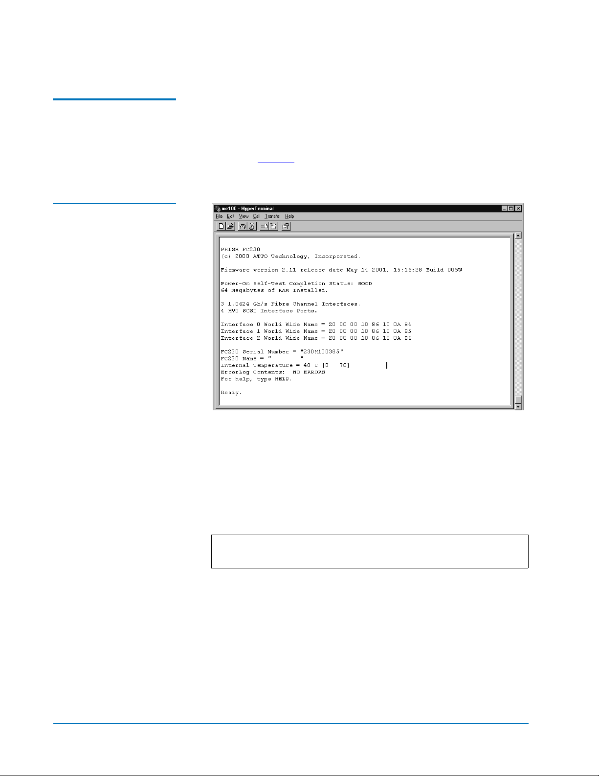
Start the FC230 Services Software
Figure 3 POST Output
Screen
To start FC230 services software:
0
1 Turn on the library or cycle the library power.
2 Upon power-up, the POST output scrolls past the PC screen,
shown in figure 3
, and the services software is immediately
available.
3 If the initial screen is not displayed, check the PC COM port
settings then power cycle the library.
4 Press <Enter> when POST completes and Ready displays. The PC is
now in command line mode.
If this is an initial installation, or a replacement FC230 board has
been installed, the HyperTerminal screen may not display
characters that are entered at the keyboard.
Note: Firmware version 2.11 or higher automatically enables
echo mode.
5 Enter the following commands to enable echo mode:
a Type set serialportecho enabled, then press <Enter>.
b Type saveconfiguration, then press <Enter>.
Wait for the Ready prompt before proceeding.
c Type firmwarerestart, then press <Enter>.
The POST screen displays and the FC230 services software is now
ready for use.
6 FC230 Router Configuration
Page 7

ATL P-Series Library User’s Guide Addendum - Prism FC230 Router
6331121-03, Ver. 3, Rel. 2
August 2002
Upgrade the FC230 Firmware
If a new version of FC230 firmware is available, use the following
0
procedure to download the new firmware to the FC230 board:
1 Copy the new firmware file to a directory on the service PC.
2 Set the FC230 baud rate and the HyperTerminal baud rate to
115200 using the following steps (this speeds the firmware
download process):
a At the Ready prompt type set serialportbaudrate 115200,
then press <Enter>.
b Type saveconfiguration, then press <Enter>.
Wait for a new Ready prompt.
c From the HyperTerminal menu (located at the top of the
screen) select
d
From the HyperTerminal menu select File/Properties/
Connect To tab/ Configure button.
e
Set the baud rate to 115200.
f From the HyperTerminal menu, select Call/Connect.
Note: Press <Enter> until you see the ready prompt.
Call/Disconnect.
At the Ready prompt:
3
a Type saveconfiguration and then press <Enter>.
b Type firmwarerestart and then press <Enter>.
c Type zmodem receive and then press <Enter>.
4 From the HyperTerminal menu at the top of the screen select:
Transfer/Send File
5
Browse to the location of the new firmware file:
xxx.IMA
In the Send File dialog box, select protocol:
6
zmodem
Click the Send button.
7
The firmware download begins and takes a few minutes to
complete. When the download is complete a new
Ready prompt
appears on the HyperTerminal screen.
8 At the Ready prompt, power cycle the library.
Note: The library has to be power cycled for the new firmware
to take effect.
FC230 Router Configuration 7
Page 8

ATL P-Series Library User’s Guide Addendum - Prism FC230 Router
6331121-03, Ver. 3, Rel. 2
August 2002
Confirm the new firmware revision is displayed in the
HyperTerminal screen as the software comes ready. Wait for the
Ready prompt.
9 Reset the FC230 and the service PC back to 9600 baud:
a At the Ready prompt, type set serialportbaudrate 9600 and
then press
b Type saveconfiguration, then press <Enter>.
<Enter>.
Scan the SCSI Buses 0
Wait for a new
c From the HyperTerminal menu, located at the top of the screen,
Call/Disconnect.
select
d From the HyperTerminal menu select File/Properties/
Connect To tab/Configure button
e Set the baud rate to 9600.
f From the HyperTerminal menu select Call/Connect.
Ready prompt.
.
Use the following procedure to confirm that the SCSI buses are cabled
properly and the SCSI IDs are properly set, as shown in figure 4
1 Connect the serial cable to the RJ-45 connector of the first FC230
.
board in the library.
2 Cycle power on the library to start the FC230 services software.
3 At the Ready prompt:
a Type scsitargets 0, then press <Enter> as shown in figure 4.
This command scans and displays all SCSI devices found on
SCSI bus 0 - the robotics controller and drives 0 and 1.
b Type scsitargets 1, then press <Enter> as shown in figure 4.
Scans bus 1 - displays drives 2 and 3.
c Type scsitargets 2, then press <Enter>.
Scans bus 2 - displays drives 4 and 5.
d Type scsitargets 3, then press <Enter>.
Scans bus 3 - displays drives 6 and 7.
4 Move the serial cable to the RJ-45 connector of the second FC230
board in the library.
5 Press <Enter>.
Ready is displayed on the screen. The PC is now in command line
mode.
8 FC230 Router Configuration
Page 9

ATL P-Series Library User’s Guide Addendum - Prism FC230 Router
6331121-03, Ver. 3, Rel. 2
August 2002
If this is an initial installation, or a replacement FC230 board has
been installed, the HyperTerminal screen may not display
characters that are entered at the keyboard.
Note: Firmware version 2.11 or higher automatically enables
echo mode.
6 Enter the following commands to enable echo mode:
a Type set serialportecho enabled, then press <Enter>.
b Type saveconfiguration, then press <Enter>.
Wait for the Ready prompt before proceeding.
c Type firmwarerestart, then press <Enter>.
The POST screen displays and the FC230 services software is ready
for use.
7 At the Ready prompt type scsitargets 0, then press <Enter>.
S
cans bus 0 [of 2nd router board] and displays drives 8 and 9.
Figure 4 SCSI Bus Scan
Screen
CLI Command Types 0
Fibre Channel CLI commands have four types of operation:
• Immediate—causes an immediate action; not preceded by a get or
set operation
• Get—returns the current value of a parameter (abbreviated “g”)
• Set—changes the value of a parameter (abbreviated “s”).
CLI Command Types 9
Page 10

ATL P-Series Library User’s Guide Addendum - Prism FC230 Router
6331121-03, Ver. 3, Rel. 2
August 2002
• Usage—if an operation type cannot be determined, the “Usage”
form is assumed and a brief help message appears.
Many Set commands require a SaveConfiguration command to take
effect. When this is required, an asterisk appears next to the command
line prompt.
CLI Command Syntax 0
The information below can help you make proper CLI entries.
Number and String Entry
Command Entry 0
List of Abbreviations 0
Decimal numbers may be entered raw (ex: 123), octal numbers must be
0
preceded by “0” (ex: 0713), and hexadecimal numbers must be
preceded by the C-style “0x” prefix (ex: 9x1FA4).
Quoted strings are treated as a single parameter for any command that
expects character input, regardless of space within the string.
The following is a list of symbols used commonly used with
commands:
• [ ] indicates required entry
• < > indicates optional entry
• | indicates choose one entry
CLI commands are not case sensitive. Upper and lowercase characters
have been used in this document to aid readability.
The following list of abbreviations are used in command lines:
• fp: Fibre Channel port number (0 - 2)
• fl: Fibre Channel LUN (0 - 31)
• sb: SCSI bus number (0 - 3)
• st: SCSI target ID (1 - 15)
• sl: SCSI LUN (0 - 7)
10 CLI Command Syntax
Page 11

ATL P-Series Library User’s Guide Addendum - Prism FC230 Router
6331121-03, Ver. 3, Rel. 2
August 2002
Fibre Channel Services Command List 0
This section provides a list of currently available Fibre Channel
Services Software commands. Most commands are available for both
the FC230 and FC310 bridges; shaded commands are supported by the
FC230 bridge only.
Command Description Default Syntax
AddressMap Sets the current operating mode of
the FC ports
AutoMap (Immediate) Automatically maps all currently
operational SCSI devices attached to
the Fibre Channel bridge across 1, 2,
and all 3 ports, as defined by the
user.
BootFibreDelay Sets the time in seconds for the Fibre
Channel bridge to wait before
announcing its presence to the Fibre
switch.
BootScanPorts Used to specify which FC port
should be used to assign devices
within a boot scan.
Addressmap B (port failover)
overrides this command.
ClearEvent
(Immediate)
DisplayEvent
(Immediate)
Clears the contents of the event log. clearevent
Displays the contents of the event
log. The log is filtered by the current
switch settings as described in the
DispEvent section.
A set addressmap [A | B [1 | 2]]
get addressmap
automap < [fp] | [fp [fp]] | [fp [fp [fp]]] >
(Typing automap by itself distributes maps
across all 3 ports.)
30 set bootfibredelay [0 | 15 | 30]
get bootfibredelay
Auto set bootscanports [fp [fp [fp]]] | [all] | [auto]
get bootscanports
[all] indicates that all ports will be used.
[auto] indicates that the FC bridge should
detect which ports are in use.
displayevent < all >
< all > causes the display filtering to be
temporarily suspended and all logged events
to be displayed.
Fibre Channel Services Command List 11
Page 12

ATL P-Series Library User’s Guide Addendum - Prism FC230 Router
6331121-03, Ver. 3, Rel. 2
August 2002
Command Description Default Syntax
DispEvent
Set the switches which control the filtering performed when
displaying events. Switches have the following meanings and
settings:
(subsystem) switch: mask that controls which subsystem
events are displayed. The mask is a byte value with the
following bit patterns corresponding to the currently
supported subsystems:
0x01 FCP Processor /i960
Interaction
0x02 SCSI Processor/i960
Interaction
0x04 Ethernet (Future)
0x20 NVRAM & Flash
To display the events from several different subsystems, use a
mask value equal to the logical OR of the corresponding
subsystem values. To display events from all subsystems
enter the value 3Fh for the mask.
(event_level) switch: mask that controls what reporting level
events are displayed. The mask is a byte value with the
following bit patterns corresponding to the currently
supported reporting levels:
0x01 Info; general information
0x02 Warning; unexpected situation/condition
0x04 Critical; operation limited/curtailed
0x08 Failure; hard failure
0x10 Other; otherwise not categorized
0x20 Debug; tracking events
To display events from several different reporting levels, use a
mask value equal to the logical OR of the corresponding
reporting levels. To display events for all reporting levels
enter the value 3Fh for the mask.
(status) switch: has the following two values which
correspond to the status of the events to be displayed:
all All events, regardless of their status values are displayed.
ngood Only events with a status other than good are
displayed.
set dispevent [subsystem] [event_level]
[status]
get dispevent
3Fh
Example: 0x01 0x01 all
3Fh
all
DispFcPortDB
(Immediate)
12 Fibre Channel Services Command List
Displays the contents of the
specified FC port’s internal port
database.
dispfcportdb <fp>
Page 13

ATL P-Series Library User’s Guide Addendum - Prism FC230 Router
Command Description Default Syntax
6331121-03, Ver. 3, Rel. 2
August 2002
EccLog Displays/clears ECC log statistics
for the FC bridge.
EthernetSpeed Sets/displays the Ethernet speed of
the card
FcConnMode Set the connection mode for the
FC230 to arbitrated loop or point-topoint. Applies to all three Fibre
Channel ports on each board.
FcFairArb Turn on or off the FC-AL arbitration
fairness. Applies to all three Fibre
Channel ports on each board.
FcFrameLength Specify the maximum number of
payload bytes in a Fibre Channel
frame. If the frame length is not
specified, the current frame length is
displayed.
FcFullDuplex Enables/disables full duplex
communication between the FC
bridge and other Fibre devices.
set ecclog clear
get ecclog
The get command displays the statistics. The
set commands clears the statistics.
auto set EthernetSpeed [10 | 100 | auto]
get EthernetSpeed
ptp set fcconnmode [loop | ptp]
get fcconnmode
enabled set fcfairarb [enabled | disabled]
get fcfairarb
2048
bytes
enabled set fcfullduplex [enabled | disabled]
set fcframelength [512 | 1024 | 2048]
get fcframelength
get fcfullduplex
FcHard Enable or disable Fibre Channel
hard address assignment. Under
soft addressing the FC230 loop
address is assigned during loop
initialization.
FcHardAddress Set the value used as the FC-AL
hard address. There is an individual
hard address value for each of the
three Fibre Channel ports on each
board.
FcInitiator Enables/disables the FC bridge as
an initiator on the Fibre network.
This functionality is required for
features such as Extended Copy to
locate and send commands to Fibre
devices.
hard set fchard [enabled | disabled]
get fchard
port 0 =
0x03
port 1 =
0x04
port 2 =
0x05
disabled set fcinitiator [enabled | disabled]
set fchardaddress [fp [address]]
get fchardaddress [fp]
get fcinitiator
Fibre Channel Services Command List 13
Page 14

ATL P-Series Library User’s Guide Addendum - Prism FC230 Router
6331121-03, Ver. 3, Rel. 2
August 2002
Command Description Default Syntax
FcPortFailure
(Immediate)
FcPortList
(Immediate)
FcSCSIBusyStatus Specify the SCSI status value
FcTargets (Immediate) Displays information about every
FcWWName Reports the World Wide Name
Controls the behavior of FC ports
while the bridge is in AddressB
(failover) mode.
List the available Fibre Channel
ports and their current status.
returned when the FC230 is unable
to accept a SCSI command due to a
temporary lack of internal
resources.
FC device visible to a bridge
operating in initiator mode.
(WWN) of the referenced Fibre
Channel interface.
fcportfailover fp [recover | force [loopdown
| portdown | isperr]]
The recover option should be selected for
actual failover operation.
The force option forces a failure for testing
and demonstration purposes by simulating
loss of FC synchronization (loopdown), ISP
chip failure detected by fabric (portdown), or
internal ISP chip error (isperr).
fcportlist
QFULL set fcscsibusystatus [busy | qfull]
get fcscsibusystatus
fctargets <fp>
get fcwwname [portnumber]
FibreBridgeModel Report the specific FC230 model
information.
FibreBridgeName Specify the 8-character name
assigned to the FC bridge.
FibreBridgeTargetLUNSpecify the soft target LUN used by
the FC bridge when addressed by
the host. This LUN is taken from
NVRAM.
FirmwareRestart
(Immediate)
Help (Immediate) Displays a list of available
IdentifyFibreBridgeCauses the “Fault” LED on the
Reboot the FC bridge firmware. firmwarerestart
commands. When the optional
command name is present, detailed
command-specific information is
displayed.
FC230 board to blink continuously
until disabled.
get fibrebridgemodel
“........” set fibrebridgename [name]
get fibrebridgename
14 (all FC
ports)
disabled set identifyfibrebridge [enabled | disabled]
set fibrebridgetargetlun [0 - 31]
help [command name]
get identifyfibrebridge
14 Fibre Channel Services Command List
Page 15

ATL P-Series Library User’s Guide Addendum - Prism FC230 Router
Command Description Default Syntax
6331121-03, Ver. 3, Rel. 2
August 2002
Info (Immediate) Displays version numbers and other
product information for key FC
bridge components.
IPAddress Sets/displays the current IP address
of the FC
IPDHCP Enables/disables the FC to request
an IP address from the network.
Requires the bridge be attached to a
network with at least one DHCP
server.
IPGateway Sets/displays the current default
gateway. If IPDHCP is enabled, the
get command reports the current IP
gateway assigned by the
nameserver.
IPSubnetMask Sets/displays the current subnet
mask. IF IPDHCP is enabled, the get
command reports the current IP
subnet mask assigned by the
nameserver.
LicensedOption Enables/disables a user-defined
licensed option.
info
set IPAddress xxx.xxx.xxx.xxx
get IPAddress
enabled set IPDHCP [enabled | disabled]
get IPDHCP
set IPGateway xxx.xxx.xxx.xxx
get IPGateway
set IPSubnetMask xxx.xxx.xxx.xxx
get IPSubnetMask
none set licensedoption [option_name [enabled |
disabled]]
get licensedoption
LogEvent
Sets the switches which control the filtering performed when
logging events. The switches have the following meanings
and settings:
(enabled | disabled) switch: controls whether or not events
logging is enabled or disabled.
(subsystem) switch: same as switch for DispEvent in previous
section
(event_level) switch: same as switch for DispEvent in
previous section
(status) switch: same as switch for DispEvent in previous
section
MaxEnclTempAlrm Sets/displays the maximum
enclosure temperature alarm of the
unit in degrees C (5-40 degrees C).
The get option reports whether a particular
option is enabled.
disabled set logevent [enabled | disabled] |
[[subsystem] [event_level] [status]]
get logevent
70 degrees
Centigrade
set maxencltempalrm [5 - 40]
get maxencltempalrm
Fibre Channel Services Command List 15
Page 16

ATL P-Series Library User’s Guide Addendum - Prism FC230 Router
6331121-03, Ver. 3, Rel. 2
August 2002
Command Description Default Syntax
MinEnclTempAlrm Sets/displays the minimum
enclosure temperature alarm of the
unit in degrees C (5-40 degrees C).
OEMConfigFile Reports the name (i.e., the contents
of the first record) of the OEM
configuration file stored in
persistent memory.
ParityLog Displays/clears the parity error
statistical log for the FC bridge.
Reserve (Immediate)
Reservation of the FC230 is implicit; once the configuration
image is changed by any user of services (Serial/Ethernet/
Etc.,) the FC230 becomes RESERVED. Performing a
SaveConfiguration, RestoreConfiguration or FcRestart
RELEASES the FC230 so that other devices may access it.
When the FC230 services interface is reserved, set commands
are unavailable, but get commands are available. Note that at
least one service interface always has access to the FC230 at all
times. This interface always reports a RELEASED status, since
it may issue set commands.
0 degrees
Centigrade
ATTO get oemconfigfile
set minencltempalrm [5 - 40]
get minencltempalrm
set parity clear
get paritylog
The get command displays the statistics. The
set commands clears the statistics.
reserve
RestoreConfigurati
on (Immediate)
RouteChange
(Immediate)
RouteDisplay
(Immediate)
Restore to factory default
configuration or the last saved
configuration. The new
configuration must be saved to take
effect.
Map a Fibre Channel port and LUN
to a SCSI bus, target, and LUN.
Valid route change entries are:
fp (0-2)
fl (0-31)
sb (0-3)
st (0-15)
sl (0-7).
List the currently mapped Fibre
Channel-to-SCSI routes.
restoreconfiguration [default | saved]
routechange [fp] [fl] [sb] [st] [sl]
routedisplay
routedisplay [fp]
routedisplay [online | offline]
routedisplay [fp [fl]]
routedisplay [fp [online | offline]]
16 Fibre Channel Services Command List
Page 17

ATL P-Series Library User’s Guide Addendum - Prism FC230 Router
6331121-03, Ver. 3, Rel. 2
Command Description Default Syntax
RouteOffline Set the status of a route to offline. set routeoffline [fp] [fl]
get routeoffline [fp] [fl]
RouteOnline Set the status of a route to online. set routeonline [fp] [fl]
get routeonline [fp] [fl]
August 2002
SaveConfiguration
(Immediate)
ScsiInitID Specify the SCSI initiator ID to be
ScsiPortList
(Immediate)
ScsiPortReset
(Immediate)
ScsiPortResetOnSta
rtup
ScsiPortSelTimeout Show the time (msec) that the router
ScsiPortSyncTransferSpecify whether synchronous SCSI
Save the new configuration. If a
firmware restart is required to make
the change, the user is prompted to
confirm the restart. The user can
override the confirmation request
by indicating the override value on
the command line.
used on the specified SCSI port.
List the available SCSI ports and
their status.
Reset the specified SCSI bus. scsiportreset [sb]
Specify whether the SCSI port
should be reset on power-up.
waits for a response from a SCSI
device on the selected port after a
selection request.
transfers should be negotiated with
devices on the specified SCSI port.
saveconfiguration < restart | norestart >
0x07 (all
SCSI buses)
Reset each
SCSI bus
on startup
256 msec set scsiportseltimeout [sb [256 | 128 | 64 | 32
enabled set scsiportsynctransfer [[sb] [enabled |
set scsiinitid [sb [0-15]]
get scsiinitid [sb]
scsiportlist
set scsiportresetonstartup [sb [enabled |
disabled]]
get scsiportresetonstartup [sb]
| 16 | 8 | 4 | 2 | 1]]
get scsiportseltimeout [sb]
disabled]]
get scsiportsynctransfer [sb]
ScsiPortTaggedQueu
ing
ScsiPortUltra2 Specify whether the selected port
ScsiPortWideTransferSpecify whether wide SCSI transfers
ScsiTargets List the SCSI devices that are on the
ScsiTermination Set the internal termination of the
SerialNumber Report the FC230 board serial
Specify whether tagged command
queuing is allowed on the SCSI port.
supports Ultra2 (LVD) transfers.
should be negotiated.
referenced SCSI bus.
referenced SCSI port.
number.
Fibre Channel Services Command List 17
disabled set scsiporttaggedqueuing [sb [enabled |
disabled]]
get scsiporttaggedqueuing [sb]
set scsiportultra2 [sb [enabled | disabled]]
get scsiportultra2 [sb]
enabled set scsiportwidetransfer [sb [enabled |
disabled]]
get scsitargets [sb]
enabled set scsitermination [sb [enabled | disabled]]
get scsitermination [sb]
230x... get serialnumber
Page 18

ATL P-Series Library User’s Guide Addendum - Prism FC230 Router
6331121-03, Ver. 3, Rel. 2
August 2002
Command Description Default Syntax
SerialPortBaudRate Set the baud rate for the FC230 serial
port (2400, 9600, 19200, 38400, 57600,
or 115200).
SerialPortEcho Enables/disables echoing of
keyboard input.
SerialPortHandshakeSet the data handshaking method
used for controlling the flow
between the transmitter and
receiver (hardware, software, or
none).
SerialPortStopBits Set the number of stop bits for the
FC230 serial port (1 or 2).
SpeedWrite Enables/disables the Speed Write
command. Speed Write is designed
to improve the performance of FCP
WRITE commands to SCSI devices
attached to the FC bridge.
SpeedWriteDefault Sets Speed Write functionality to be
enabled for subsequent SCSI
devices mapped to the FC bridge.
9600 set serialportbaudrate [rate]
get serialportbaudrate
disabled set serialportecho [enabled | disabled]
none set serialporthandshake [hard | xon | none]
get serialporthandshake
1 set serialportstopbits [1 | 2]
get serialportstopbits
disabled set speedwrite [sb st sl | all] [enabled |
disabled]
get speedwrite [sb st sl | all]
“sb” specifies SCSI bus, “st” specifies SCSI
target, and “sl” specifies SCSI LUN.
disabled set speedwritedefault [enabled | disabled]
get speedwritedefault
Temperature Report the unit temperature in
degrees C.
VerboseMode
Sets the Command Line Interface to display extended
information about a parameter when the help command is
given. When verbose mode is enabled, parameter values are
generally preceded by labels in responses to the get
commands. Only the parameter value is output when verbose
mode is disabled.
XCDevices
Allows the user to obtain information about the devices used
in a particular Extended Copy command. The Extended Copy
command to query is specified by the CmdNumber for the
command as presented in the SCStatus CLI command. The
‘DeviceType’ field displays the SCSI device type for each
device. The ‘VendorId’, ‘ProductId’, and ‘Serial Number’
fields display the SCSI Inquiry data identifying the device.
Note that the SerialNumber field displays up to 16 of the least
significant digits of the device serial number. the
‘DataDirection’ field specifies whether a device is a data
source, a data destination, or both as specified in the segment
descriptors of an Extended Copy command; the field can take
on the values [Source | Destination | Both].
get temperature
enabled set verbose [enabled | disabled]
get verbose
get XCDevices [CmdNumber]
18 Fibre Channel Services Command List
Page 19

ATL P-Series Library User’s Guide Addendum - Prism FC230 Router
Command Description Default Syntax
6331121-03, Ver. 3, Rel. 2
August 2002
XCError
Retrieves any SCSI sense data returned by an Extended Copy
command as the result of an error. The Extended Copy
command to query is specified by the CmdNumber for the
command as presented in the XCStatus CLI command. The
‘SCSIStatus’, ‘SenseKey’, ‘ASC’, and ‘ASCQ’ fields display the
sense data returned by the Extended Copy command. If a
device involved in the command’s data transfer also returned
sense data, that device’s serial number is displayed in the
‘DeviceId’ field and that device’s sense data is displayed in
the ‘DStat’, ‘DSK’, ‘DASC’, and ‘DASCQ’ fields. Any field that
does not contain valid data is filled in with 00.
XCStatus
Allows the user to poll for the status of Extended Copy
commands issued to the FC. The ‘CmdNumber’ field presents
a unique identifier for a particular Extended Copy command.
The ‘ListId’ field displays the List ID specified in the CDB of
the Extended Copy command. The ‘HostId’ field displays the
8-byte Node Name of the Fibre Channel host that issued the
Extended Copy command. The ‘Status’ field displays the
current state of the Extended Copy command, which can be
[Initializing | Active | Done | Error]. The ‘Transferred’ field
displays the amount of data transferred by the Extended
Copy command in MB.
get SCError [CmdNumber]
get XCStatus
Zmodem (Immediate) Transfer a firmware image or
NVRAM parameter file to or from
the router using ZMODEM file
transfer protocol.
zmodem [send [filename] | receive]
Fibre Channel Services Command List 19
 Loading...