

Page 1

ACL 4/52 Automated Tape Library
for DLT Cartridges
Software Interface Guide
6211225-03
Version 3.0
Page 2

Page 3

6211225-03, Version 3.0, October 25, 1996, Made in USA.
© Copyright 1996, ATL Products, Inc. All rights reserved.
Your right to copy this manual is limited by copyright law. Making copies or adaptations without prior written authorization of
ATL Products, Inc. is prohibited by law and constitutes a punishable violation of the law.
ATL Products, Inc. provides this publication “as is” without warranty of any kind, either express or implied, including but not
limited to the implied warranties of merchantability or fitness for a particular purpose. ATL Products, Inc. may revise this
publication from time to time without notice.
FCC STATEMENT
This equipment has been tested and found to comply with the limits for a Class A digital device, pursuant to Part 15 of the FCC
Rules. These limits are designed to provide reasonable protection against harmful interference when the equipment is operated
in a commercial environment. This equipment generates, uses, and can radiate radio frequency energy and, if not installed and
used in accordance with the instruction manual, may cause harmful interference to radio communications.
Any changes or modifications made to this equipment may void the user's authority to operate this equipment.
Operation of this equipment in a residential area may cause interference in which case the user at his own expense will be
required to take whatever measures may be required to correct the interference.
This device complies with Part 15 of the FCC Rules. Operation is subject to the following conditions: (1) this device may not
cause harmful interference, and (2) this device must accept any interference received, including interference that may cause
undesired operation.
CISPR-22 WARNING!
This is a Class A product. In a domestic environment this product may cause radio interference in which case the user may be
required to take adequate measures.
ACHTUNG!
Dieses ist ein Gerät der Funkstörgrenzwertklasse A. In Wohnbereichen können bei Betrieb dieses Gerätes Rundfunkstörungen
auftreten, in welchen Fällen der Benutzer für entsprechende Gegenmassnahmen verantwortlich ist.
ATTENTION!
Ceci est un produit de classe A. Dans un environment domestique, ce produit peat causer des interférences radio lectriques. Il
appartienl alors a l'utilisateur de prendre les mesures appropriées.
NOTICE FOR USA AND CANADA ONLY
If shipped to USA, use the UL LISTED power cord specified below for 100-120 V operation. If shipped to CANADA, use the
CSA CERTIFIED power cord specified below for 100-120V operation.
Plug Cap Parallel blade with ground pin (NEMA 5-15P Configuration)
Cord Type: SJT, three 16 or 18 AWG wires
Length Maximum 15 feet
Rating Minimum 10 A, 125 V
LIRE LA REMARQUE DANS LE MODE D'EMPLOI
ATTENTION
Page 4

REMARQUE
CETTE REMARQUE NE CONCERNE QUE LES ÉTATS-UNIS ET LE CANADA.
En cas d'envoi aux États-Unis, utiliser le cordon d'alimentation certifié UL et convenant pour 100-120 V.
En cas d'envoi au CANADA, utiliser le cordon d'alimentation CERTIFIÉ CSA et convenant pour 100-120 V.
Fiche Broches paralléus avec une broche de mise à la terre (configuration NEMA 5-15P)
Cordon Type: SJT, trifilaire 16 ou 18 AWG
Longeur Maximum 15 pieds
Capacité Minimum 10 A, 125 V
ZU IHRER SICHERHEIT
Vorsicht
Um Feuergefahr und die Gefahr eines elektrischen Schlages zu vermeiden. darf das Gerät weder Regen noch Feuchtigkeit
ausgesetzt werden.
Um einen elektrischen Schlag zu vormeiden, darf das Gehäuse nicht geöffnet werden. Überlassen Sie Wartungsarbeiten stets
nur einem Fachmann.
Achtung
Da der interne Laserstrahl in lhre Augen eindringen und Verletzungen verursachen kann, darf das Gehäuse nicht selbst geöffnet
werden. Überlassen Sie Wartungearbeiten stets nur einem Fachmann.
Die Verwendung von Brillen, Kontaktlinsen usw.vergrössert die Gefahr.
Zur besonderen Beachtung
Zur Sicherheit
Sollte ein fester Gegenstand oder Flüssigkeit in das Geräteinnere gelangen, trennen Sie das Gerät von der Wandsteckdose ab und
lassen Sie es von einem Fachmann überprufen, bevor Sie es weiter verwenden.
Zum Abziehen des Kabels fassen Sie stets am Stecker und niemals am Kabel selbst an.
Zur Aufstellung
Stellen Sie das Gerät weder auf einer weichen Unterlage (z. B. Decke, T eppich) noch in der Nahe von Vorhangen, Tapeten usw,
auf, da hierdurch die Ventilationsöffnungen blockiert werden können.
Zur Reiningung
Verwenden Sie zur Reiningung des Gehäuses, des Bedienungspultes und der Bedienungselemente ein trockenes, weiches Tuch
oder ein weiches, leicht mit mildem Haushaltsreiniger angefeuchtetes Tuch. Lösemittel wie Alkohol oder Benzin dürfen nicht
verwendet werden, da diese die Gehäuseoberfläche ungreifen.
Page 5

Table of Contents
Introduction
Purpose.......................................................................................................................1-3
Conventions Used in this Guide ................................................................................1-3
Related Documentation..............................................................................................1-4
ATL Products Technical Publications.................................................................1-5
ATL Products BBS..............................................................................................1-5
ATL Products Internet Web Site.........................................................................1-5
Theory of Operation
Chapter Overview......................................................................................................2-3
Library Description....................................................................................................2-3
SCSI Implementation Philosophy..............................................................................2-4
Medium Changer Elements........................................................................................2-4
Medium Transport Element.................................................................................2-5
Storage Elements.................................................................................................2-5
Import/Export (Load Port) Elements...................................................................2-5
Data Transfer Elements.......................................................................................2-5
Events.........................................................................................................................2-6
Power Cycle ........................................................................................................2-7
Library Unit Off-line/Standby.............................................................................2-7
Library Unit On-line Initialization Failure..........................................................2-7
Library Unit Door Opened..................................................................................2-7
Library Unit Stopped...........................................................................................2-7
Accessed Load Port.............................................................................................2-7
Maximum Temperature Exceeded ......................................................................2-7
Operational Sequences........................................................................................2-8
Power-On Sequence......................................................................................2-8
Door Opened Sequence ................................................................................2-8
System Stopped Sequence............................................................................2-9
On-line Initialization Sequence ....................................................................2-9
Library Unit Inventory Sequence ...............................................................2-10
Off-line Sequence.......................................................................................2-11
Automatic Drive Cleaning Sequence..........................................................2-11
Configuration Procedures ........................................................................................2-12
“DIAG” Interface..............................................................................................2-12
ACL 4/52 Software Interface Guide
Document 6211225-03
Version 3.0
Table of Contents v
Page 6

ACL 4/52 Software Interface Guide
Document 6211225-03
Version 3.0
Control Panel Menu Mode ............................................................................... 2-13
Error Recovery Procedures..................................................................................... 2-14
Internal Error Recovery.................................................................................... 2-14
Operator Recovery............................................................................................ 2-14
System Performance ............................................................................................... 2-15
Key Performance Items.................................................................................... 2-15
Typical Application Enhancements.................................................................. 2-15
System Diagnostic Support..................................................................................... 2-16
Host Interface Diagnostic Error Codes............................................................. 2-16
Off-line Diagnostics via the “DIAG” Port ....................................................... 2-16
Software Interfaces
Chapter Overview ..................................................................................................... 3-3
SCSI Interface........................................................................................................... 3-3
Reset Sequence................................................................................................... 3-4
Supported Messages........................................................................................... 3-4
Abort ............................................................................................................ 3-5
Bus Device Reset......................................................................................... 3-5
Command Complete .................................................................................... 3-5
Disconnect (from Target to Initiator)........................................................... 3-5
Identify (Initiator to Target)......................................................................... 3-6
Identify (Target to Initiator)......................................................................... 3-6
Save Data Pointer......................................................................................... 3-6
Supported Operational Commands..................................................................... 3-7
Initialize Element Status (07h)..................................................................... 3-9
Initialize Element Status with Range (E7h)............................................... 3-10
Inquiry (12h).............................................................................................. 3-12
Log Sense Command (4Dh)....................................................................... 3-15
Mode Select Command (15h).................................................................... 3-19
Mode Sense (1Ah) ..................................................................................... 3-25
Move Medium (A5h)................................................................................. 3-35
Position To Element (2Bh) ........................................................................ 3-37
Prevent/Allow Medium Removal (1Eh).................................................... 3-38
Read Element Status (B8h)........................................................................ 3-40
Ready Inport (DEh).................................................................................... 3-53
Release (17h) ............................................................................................. 3-54
Reserve (16h)............................................................................................. 3-55
Request Sense (03h)................................................................................... 3-58
Request Volume Element Address (B5h).................................................. 3-61
Rezero Unit (01h) ...................................................................................... 3-75
Send Diagnostic (1Dh)............................................................................... 3-76
vi Table of Contents
Page 7

ACL 4/52 Software Interface Guide
Document 6211225-03
Send Volume Tag (B6h)............................................................................ 3-78
Test Unit Ready (00h)................................................................................ 3-80
Sense Data Values
Introduction...............................................................................................................A-1
Control Panel Messages
Introduction...............................................................................................................B-1
System States ............................................................................................................B-2
Operator Messages....................................................................................................B-4
Menu Mode Messages ..............................................................................................B-5
Automatic Drive Cleaning Discussion
Purpose and Scope ....................................................................................................C-3
Drive Cleaning Modes ..............................................................................................C-3
Host Initiated Cleaning Mode ............................................................................C-3
Fully Automatic Cleaning Mode........................................................................C-3
Selection of Cleaning Mode......................................................................................C-4
Diagnostic Software ...........................................................................................C-4
Control Panel......................................................................................................C-4
Mode Select Command (Host Initiated).............................................................C-4
Reporting of Cleaning Mode.....................................................................................C-5
Diagnostic Software ...........................................................................................C-5
Mode Sense Command (Host Initiated) .............................................................C-5
Cleaning Cartridges...................................................................................................C-5
Capacity..............................................................................................................C-5
Identification.......................................................................................................C-6
Storage and Tracking..........................................................................................C-6
Monitoring Usage...............................................................................................C-7
Element Status Information................................................................................C-7
Monitoring Drives.....................................................................................................C-8
Drive Interface....................................................................................................C-8
Drive Monitoring................................................................................................C-8
Initiating Drive Cleaning Operations........................................................................C-8
Selection of Cleaning Cartridges ..............................................................................C-9
Media Movement to the Drive..................................................................................C-9
Supervising the Drive Cleaning Operation.............................................................C-10
Media Movement from the Drive ...........................................................................C-10
Unloading Cleaning Cartridges...............................................................................C-11
Version 3.0
Table of Contents vii
Page 8

ACL 4/52 Software Interface Guide
Document 6211225-03
Version 3.0
Exabyte EXB-120 Emulation Discussion
Purpose and Scope ....................................................................................................D-3
Host Interface Modes................................................................................................D-3
Standard Interface Mode ....................................................................................D-3
Exabyte EXB-120 Interface Mode.....................................................................D-3
Selection of Host Interface Mode .............................................................................D-4
Diagnostic Software ...........................................................................................D-4
Control Panel......................................................................................................D-4
Mode Select Command (Host Initiated).............................................................D-4
Reporting of Host Interface Mode ............................................................................D-5
Diagnostic Software ...........................................................................................D-5
Mode Sense Command (Host Initiated) .............................................................D-5
SCSI Command Differences.....................................................................................D-6
Inquiry (12h).......................................................................................................D-6
Move Medium (A5h)..........................................................................................D-6
Read Element Status (B8h) ................................................................................D-6
Receive Diagnostic Results (1Ch)......................................................................D-7
Request Sense (03h) ...........................................................................................D-7
Send Diagnostic (1Dh) .......................................................................................D-7
Write Firmware (C1h)........................................................................................D-7
Unsolicited Message Differences.......................................................................D-7
Exabyte Emulation Design Philosophy.....................................................................D-8
Glossary
Index
viii Table of Contents
Page 9

List of Figures
Figure 1: Control Panel .........................................................................................2-6
Figure 2: Read Element Status Data General Structure ......................................3-42
Figure 3: Request Volume Element Address Data General Structure ................3-63
ACL 4/52 Software Interface Guide
Document 6211225-03
Version 3.0
List of Figures ix
Page 10

x
Page 11

List of Tables
Table 1: Related Documentation .......................................................................... 1-4
Table 2: Supported Operational Commands......................................................... 3-8
Table 3: Initialize Element Status Cmd................................................................ 3-9
Table 4: Initialize Element Status with Range Command.................................. 3-10
Table 5: Inquiry Command................................................................................. 3-12
Table 6: Standard Inquiry Data........................................................................... 3-13
Table 7: Log Sense Command............................................................................ 3-15
Table 8: Supported Log Pages............................................................................ 3-16
Table 9: Medium Changer Statistics Page.......................................................... 3-17
Table 10: Log Parameter....................................................................................... 3-17
Table 11: Supported Log Parameter Codes.......................................................... 3-18
Table 12: Mode Select Command ........................................................................ 3-19
Table 13: Mode Select Data - Vendor Unique Page 20h...................................... 3-20
Table 14: Mode Select Data - Vendor Unique Page 00h...................................... 3-21
Table 15: Mode Select Data - Element Address Assignment Page...................... 3-23
Table 16: Mode Sense Command......................................................................... 3-25
Table 17: Mode Sense Data Header ..................................................................... 3-27
Table 18: Mode Sense Data - Vendor Unique Page 00h...................................... 3-28
Table 19: Mode Sense Data - Element Address Assignment Page ...................... 3-30
Table 20: Mode Sense Data - Transport Geometry Parameters Page................... 3-32
Table 21: Mode Sense Data - Device Capabilities Data....................................... 3-33
Table 22: Mode Sense Data - Vendor Unique Page 20h...................................... 3-34
Table 23: Move Medium Command..................................................................... 3-36
Table 24: Position To Element Command............................................................ 3-37
Table 25: Prevent/Allow Medium Removal Command....................................... 3-39
Table 26: Read Element Status Command........................................................... 3-40
Table 27: Element Status Data.............................................................................. 3-43
Table 28: Element Status Page ............................................................................. 3-44
Table 29: Medium Transport Element Descriptor................................................ 3-45
Table 30: Primary Volume Tag Information........................................................ 3-46
Table 31: Storage Element Descriptor.................................................................. 3-47
Table 32: Import/Export Element Descriptor....................................................... 3-49
Table 33: Data Transfer Element Descriptor........................................................ 3-51
ACL 4/52 Software Interface Guide
Document 6211225-03
Version 3.0
List of Tables xi
Page 12

ACL 4/52 Software Interface Guide
Document 6211225-03
Version 3.0
Table 34: Ready Inport Command....................................................................... 3-53
Table 35: Release Command ............................................................................... 3-54
Table 36: Reserve Command............................................................................... 3-56
Table 37: Element List Descriptor....................................................................... 3-57
Table 38: Request Sense Command .................................................................... 3-58
Table 39: Request Sense Data.............................................................................. 3-59
Table 40: Request Volume Element Address Command .................................... 3-61
Table 41: Volume Element Address Header ....................................................... 3-64
Table 42: Element Status Page ............................................................................ 3-65
Table 43: Medium Transport Element Descriptor............................................... 3-66
Table 44: Primary Volume Tag Information ....................................................... 3-68
Table 45: Storage Element Descriptor................................................................. 3-68
Table 46: Import/Export Element Descriptor ...................................................... 3-71
Table 47: Data Transfer Element Descriptor....................................................... 3-73
Table 48: Rezero Unit Command ........................................................................ 3-75
Table 49: Send Diagnostic Command ................................................................. 3-76
Table 50: Selftest Bit Definitions ........................................................................ 3-77
Table 51: Send Volume Tag Command............................................................... 3-78
Table 52: Send Volume Tag Parameters ............................................................. 3-79
Table 53: Test Unit Ready Command ................................................................. 3-80
Table A-1: Sense Data Values (Hexadecimal)......................................................... A-2
Table B-1: System States......................................................................................... B-2
Table B-2: Operator Messages................................................................................. B-4
xii List of Tables
Page 13

ACL 4/52 Software Interface Guide
Document 6211225-03
Version 3.0
Introduction
Purpose...................................................................................................................... 1-3
Conventions Used in this Guide................................................................................ 1-3
Related Documentation............................................................................................. 1-4
ATL Products Technical Publications................................................................ 1-5
ATL Products BBS............................................................................................. 1-5
ATL Products Internet Web Site........................................................................ 1-5
1
1-1
Page 14

1-2
Page 15

Purpose
ACL 4/52 Software Interface Guide
Document 6211225-03
Version 3.0
This guide was written for software engineers developing the
application and hierarchical mass storage software that accesses the
ACL 4/52 Automated T ape Library (library). The manual describes the
SCSI-2 software interfaces, discusses performance issues as well as
error handling. The document is divided into the following sections:
• Section 1, “Introduction,” describes the purpose of this manual,
provides a list of its contents and a list of related documentation.
• Section 2, “Theory of Operation,” contains detailed discussions of
the Medium Changer Elements, Events, Operational Sequences,
Configuration and Error Recovery Procedures as well as System
Performance and Diagnostic Support issues.
• Section 3, “Softwar e Interfaces,” describes the specific terminology
of the Small Computer Systems Interface (SCSI-2).
Conventions Used in this Guide
The following conventions are used in this guide:
All binary numbers are succeeded by “b”.
All hexadecimal numbers are succeeded by “h”.
Error or attention conditions are represented in parenthesis that
translate as follows:
(SK=S ASC=AA ASCQ=QQ)
where:
S = hexadecimal sense key value
AA = hexadecimal additional sense code
QQ = hexadecimal additional sense code qualifier
Definitions of these values are located in Appendix A.
Purpose 1-3
Page 16

ACL 4/52 Software Interface Guide
Document 6211225-03
Version 3.0
Related Documentation
Table 1 is a list of all manuals associated with the ACL 4/52
Automated Tape Library. To obtain further information and/or copies
of documentation on this product, contact:
ATL Products, Inc.
1515 South Manchester Avenue
Anaheim, California 92802-2907
(714)774-6900
The part number of each document will be required at the time of
order.
Table 1: Related Documentation
Document
Number
6211221 ACL 4/52 Facilities
6211222 ACL 4/52 Operator’s
6211223 ACL 4/52 Field Service
6211224 ACL 4/52 Diagnostic
EK-TH4XX-1M DLT™2000 Series
81-108336-01 DLT™4000 Cartridge
Document Title Document Description
Planning and
Installation Guide
Guide
Manual
Software User’s
Manual
Cartridge Tape
Subsystem Owner’s
Manual
Tape Drive Product
Manual
This guide describes facility preparation and
provides the procedures for first-time installation of
the library.
This guide describes the operator accessible
components of the library and provides both
operating and troubleshooting procedures.
This document contains periodic maintenance, fault
isolation and removal/replacement procedures.
This manual provides procedures for installing and
using the ACL 4/52 Diagnostic Software.
This document describes the DLT™2000 Tape
Drive and provides operating instructions and
troubleshooting procedures.
This document describes the DLT™4000 Tape
Drive and provides operating instructions and
troubleshooting procedures.
81-60000-01 DLT™7000 Tape
Drive Product Manual
1-4 Related Documentation
This document describes the DLT™7000 Tape
Drive and provides operating instructions and
troubleshooting procedures.
Page 17

ATL Products Technical Publications
Comments or questions regarding this or any ATL Products’
documentation can be directed to the address listed on page 1-4 or by
sending email directly to the ATL Products, Inc. technical publications
group. Send all documentation related email comments and questions
to:
atl-docs@odetics.com
ATL Products BBS
The ATL Products, Inc. Bulletin Board Service (BBS) provides a
customer service conference, product support conference,
documentation conference and public-domain software conference.
product manuals, utility software, firmware updates, and other
product information may be obtained in soft copy. BBS. The BBS is
available 24 hours a day, 7 days a week at 714-780-7736.
ACL 4/52 Software Interface Guide
Document 6211225-03
Version 3.0
Modem settings for the ATL BBS are:
• 8 bits, 1 stop bit, no parity.
• support for up to 28.8 Kbps.
• modems that are also capable of V.34, V.FC
TM
V.32 bis
.
ATL Products Internet Web Site
If you are on the Internet, you may prefer to access our home page.
Documents, utility software, firmware updates, and product
information may be obtained in soft copy. You will also find Sales &
Marketing contacts along with e-mail address for customer
information and feedback. A TL Products, Inc. can be reached 24 hours
a day, 7 days a week on the internet at:
http://www.atlp.com/
TM
, V.32 terboTM, and
Related Documentation 1-5
Page 18

1-6
Page 19

ACL 4/52 Software Interface Guide
Document 6211225-03
Version 3.0
Theory of Operation
Chapter Overview.................................................................................................. 2-3
Library Description ................................................................................................2-3
SCSI Implementation Philosophy ........................................................................2-4
Medium Changer Elements...................................................................................2-4
Medium Transport Element............................................................................2-5
Storage Elements .............................................................................................2-5
Import/Export (Load Port) Elements ...........................................................2-5
Data Transfer Elements ..................................................................................2-5
Events........................................................................................................................2-6
Power Cycle ......................................................................................................2-7
Library Unit Off-line/Standby.......................................................................2-7
Library Unit On-line Initialization Failure ...................................................2-7
Library Unit Door Opened .............................................................................2-7
Library Unit Stopped.......................................................................................2-7
Accessed Load Port..........................................................................................2-7
Maximum Temperature Exceeded.................................................................2-7
Operational Sequences ....................................................................................2-8
Power-On Sequence...................................................................................2-8
Door Opened Sequence.............................................................................2-8
System Stopped Sequence ........................................................................2-9
On-line Initialization Sequence................................................................2-9
Library Unit Inventory Sequence..........................................................2-10
Off-line Sequence ....................................................................................2-11
Automatic Drive Cleaning Sequence....................................................2-11
Configuration Procedures....................................................................................2-12
“DIAG” Interface............................................................................................2-12
2
2-1
Page 20

ACL 4/52 Software Interface Guide
Document 6211225-03
Version 3.0
Control Panel Menu Mode........................................................................... 2-13
Error Recovery Procedures................................................................................. 2-14
Internal Error Recovery ................................................................................ 2-14
Operator Recovery ........................................................................................ 2-14
System Performance ............................................................................................ 2-15
Key Performance Items................................................................................. 2-15
Typical Application Enhancements............................................................ 2-15
System Diagnostic Support................................................................................. 2-16
Host Interface Diagnostic Error Codes....................................................... 2-16
Off-line Diagnostics via the “DIAG” Port.................................................. 2-16
2-2
Page 21

Chapter Overview
This chapter contains detailed discussions of the Medium Changer
Elements, Events, Operational Sequences, Configuration and Error
Recovery Procedures as well as System Performance and Diagnostic
Support issues.
Library Description
The ACL 4/52 library is the automated storage and retrieval
component of an automated tape library system. It is capable of
storing a maximum of 48 Digital Linear Tapes (DLT™) in a Fixed
Storage Array (FSA) within the library cabinet. An operator accessible
Load Port at the front of the cabinet can hold an additional four
DLT™s for a total of 52. A host computer communicates with the
library via a SCSI interface. The host controls the robotic equipment
using the SCSI-2 Medium Changer Command Set.
ACL 4/52 Software Interface Guide
Document 6211225-03
Version 3.0
In a typical operation, the host commands the robotics to transfer
DL T™s between storage bins (in the FSA), one of the four (DLT™2000,
DLT™4000, or DLT™7000) tape drives or the Load Port. Each time a
DLT™ is transferred, a gripping mechanism is moved to the DLT™s
location where it “picks” the tape, moves it to the designated (new)
location and then “places” it.
The library has fully functional media changer capability as defined by
the SCSI-2 specification. The library robotics control is directed by the
host computer. The SCSI interface enables the robotics to be driven by
the same SCSI bus as the tape drives. By providing a standard control
interface and supporting standard tape drives, the ACL 4/52 enables
host software developers to adapt their software to drive the ACL
4/52.
The ACL 4/52 has a minimal connection to any installed tape drives.
The library knows the number of drives installed and the SCSI
addresses for the tape drives. The library does not know if the drives
are on the same SCSI bus or not. This information is only relevant to
the host computer.
Chapter Overview 2-3
Page 22

ACL 4/52 Software Interface Guide
Document 6211225-03
Version 3.0
SCSI Implementation Philosophy
Using the SCSI-2 standard, the tape library has been designed so that
the host can adapt to changes in the tape library configuration.
Changes in the number of tape drives can be detected by the host.
The tape library uses the SCSI-2 Medium Changer Command Set. No
attempt is made to add complex commands to the tape library
command set. The tape library command set is complete and includes
all primitive (elemental) commands required by a host to carry out any
required complex operations.
Even though the tape library relies on the host computer to issue a
sequence of elemental commands in the correct order to complete
complex operations, it has been designed to be forgiving of system
integration errors. The tape library monitors the status of all
mechanisms and does not execute operations that could result in
damage to the library or an installed tape drive.
Medium Changer Elements
The Medium Changer Command Set accesses the address space for
the set of physical locations and mechanisms within the library unit.
The SCSI-2 term “element” is used throughout this document to refer
to one member of the tape library address space. Each “element” is a
discrete physical entity that can hold a DLT™ cartridge.
Each element within a library is represented by a unique 16 bit element
address. Each library consists of the following medium changer
elements:
• Medium Transport Element
• Storage Elements
• Data Transfer Elements
• Import/Export Elements
The Mode Sense Command can be issued to determine each library’s
configuration. The first address and number of elements for each type
(medium transport, storage, import/export or data transfer) can also
be determined using this command.
2-4 SCSI Implementation Philosophy
Page 23

Medium Transport Element
The library has a transport mechanism. This mechanism consists of the
horizontal, vertical and extension axes and a gripper.
The transport mechanism can hold a single cartridge using the gripper
and is considered one medium transport element. The transport
mechanism is used to move media between elements within the
library unit.
Storage Elements
Each library unit contains up to 48 storage elements, which correspond
to the bins in the FSA. One storage element exists per bin.
Import/Export (Load Port) Elements
ACL 4/52 Software Interface Guide
Document 6211225-03
Version 3.0
The import/export mechanism consists of a four-bin, rotating Load
Port. Each of the four bins in the Load Port has a unique element
address.
When the door is open the elements still exist, but are not “accessible”
to the medium transport.
Data Transfer Elements
A data transfer element is associated with every tape drive installed in
a library unit since each tape drive can store a single tape cartridge.
The medium transport mechanism is able to load or unload tape
cartridges into or from each tape drive.
Medium Changer Elements 2-5
Page 24
ACL 4/52 Software Interface Guide
Document 6211225-03
Version 3.0
Events
Events are system conditions created by failures or operator actions
such as opening the door or pressing the STOP switch.
Some of these events appear as states on the control panel. For a list of
event states, see Appendix B. (The control panel does not queue these
states.)
Events are recorded in sense data. Depending on the interface, the host
can obtain the sense data either in response to a Request Sense
Command or as an Unsolicited Message.
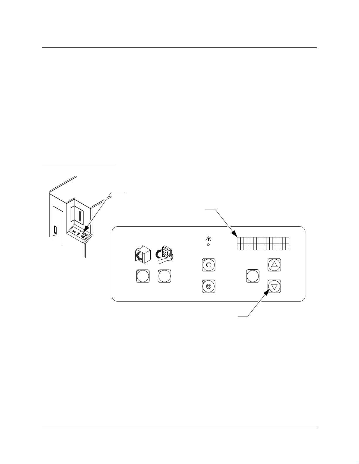
Figure 1: Control Panel
Control Panel
Status Display Area
(16 Characters/2 Lines)
FAULT
STANDBY
OPEN CLOSE
STOP
Scrolling Buttons
(Up {↑} and Down{↓})
SELECT
TA00003b/15b
The library does not support asynchronous event notification. This
simplifies the host/library interface and is acceptable since the events
happen infrequently and do not require an immediate host response.
The SCSI host can check for library events by issuing the Request
Sense command to the library. The event sense data is transmitted in
response to a Request Sense command. The library queues event
conditions for the library. The host can repeatedly issue the Request
Sense command to obtain each queued condition.
The most significant events are described in the sections that follow.
2-6 Events
Page 25

Power Cycle
When the library is powered on it generates a “Power On/Reset
Occurred” event (SK=6 ASC=29 ASCQ=00).
Library Unit Off-line/Standby
When a library is placed into the off-line/standby state, it generates a
“Logical Unit Standby Button Was Pressed” event (SK=6 ASC=80
ASCQ=09).
Library Unit On-line Initialization Failure
When a library is placed into the on-line state and the on-line
initialization fails, the library generates an event for the specific error
condition that caused the failure. The control panel indicates which
state of the initialization failed (see Appendix B for more information).
ACL 4/52 Software Interface Guide
Document 6211225-03
Version 3.0
Library Unit Door Opened
When the front door of a library is opened, the library disables all
actuators and generates a “Door Was Opened” event (SK=6 ASC=80
ASCQ=00).
Library Unit Stopped
When the library is stopped by pressing the STOP switch on the
control panel, the library disables all actuators and generates a
“System Stop Button Was Pressed” event (SK=6 ASC=80 ASCQ=07).
Accessed Load Port
When the Load Port door is closed, the library generates an “Import or
Export Element Accessed” event (SK=6 ASC=28 ASCQ=01).
Maximum Temperature Exceeded
The library monitors the ambient temperature within the system. If the
temperature exceeds 91.4
to the medium, the library generates a “Warning Safe Temperature
Exceeded” event (SK=6 ASC=88 ASCQ=00) and continues operations.
If the temperature exceeds 96.8
until the temperature decreases and generates a “Maximum
Temperature Exceeded” event (SK=4 ASC=88 ASCQ=01).
ο
F, there is a possibility for potential damage
ο
F, the library disables all actuators
Events 2-7
Page 26

ACL 4/52 Software Interface Guide
Document 6211225-03
Version 3.0
Operational Sequences
A description of operational sequences follow. They are listed in or der
of precedence. For example, if the door is opened and the STOP switch
was pressed, the door open sequence will override the system stop
sequence until it is complete.
Power-On Sequence
The following actions occur when the library is powered-on:
• The local controller for the library resets and initializes all
hardware.
• The control panel is blank.
• During this time, the library responds to the Inquiry, Request
Sense, Log Sense, and Mode Sense commands. Check Condition is
set for all other commands and the “Logical Unit is Not Ready”
condition (SK=2 ASC=04 ASCQ=00) is set in the sense data.
• When the power -on initialization is complete, the library generates
a “Power On/Reset Occurred” event (SK=6 ASC=29 ASCQ=00).
• The library sets the tape drive SCSI IDs and then resets the tape
drives
The system then moves into one of the following sequences depending
on the condition of the system.
Door Opened Sequence
Before entering the library, take the unit off-line. After the off-line
sequence is complete, it is recommended that you press the STOP
switch before opening the doors. When the door is opened, the library
is no longer operational (as viewed by the host). The following actions
occur when the door is opened:
• The control panel indicates that the door is opened.
• The library generates a “Door Was Opened” event (SK=6 ASC=80
ASCQ=00).
• If the door is opened without performing the of f-line sequence, the
system halts all library motion. Any motion command currently in
progress is aborted and Check Condition is returned to the host.
The “Door is Opened” condition (SK=2 ASC=80 ASCQ=00) is set
in the sense data.
2-8 Events
Page 27

ACL 4/52 Software Interface Guide
Document 6211225-03
Version 3.0
• While the door is opened, the library responds to the Inquiry,
Request Sense, Log Sense, and Mode Sense commands. Check
Condition is set for all other commands issued during this time
and the “Door is Opened” condition (SK=2 ASC=80 ASCQ=00) is
set in the sense data.
System Stopped Sequence
The STOP switch allows the operator to stop all power to the
actuators. The following actions occur when the system is stopped:
• The control panel indicates that the system is stopped.
• The library generates a “System Stop Button Was Pressed” event
(SK=6 ASC=80 ASCQ=07).
• The system halts all library motion. Any motion command
currently in progress is aborted and Check Condition status is
returned to host. The “System is Stopped” condition (SK=2
ASC=80 ASCQ=07) is set in the sense data.
• While the system is stopped, the library responds to the Inquiry,
Request Sense, Log Sense, and Mode Sense commands. Check
Condition status is set for all other commands issued during this
time, and the “System is Stopped” condition (SK=2 ASC=80
ASCQ=07) is set in the sense data.
On-line Initialization Sequence
The STANDBY switch allows the library to be placed on-line. The
on-line initialization sequence occurs only after the door is shut, the
system is not stopped and the library does not have the STANDBY
button pressed. The following actions occur during the on-line
initialization sequence:
• The control panel indicates that the library is performing the
on-line initialization sequence.
• The local controller for the library performs a test to check the
operation of the library unit mechanisms.
• The mechanisms are then homed.
• During this time, the library responds to the Inquiry, Request
Sense, Log Sense, and Mode Sense commands. Check Condition
status is set for all other commands, and the “Logical Unit in
Process of Becoming Ready” condition (SK=2 ASC=04 ASCQ=01)
is set in the sense data.
Events 2-9
Page 28

ACL 4/52 Software Interface Guide
Document 6211225-03
Version 3.0
• When the mechanisms are successfully tested and homed, the
library performs an inventory of its elements. (See Library Unit
Inventory Sequence).
• When initialization successfully completes, the control panel
changes to “System On-line” and the library is fully operational.
Library Unit Inventory Sequence
The library inventories its storage elements after power-up (if on-line),
upon receipt of an Initialize Element Status Command or after the
door is closed and the library is placed on-line.
• The local controller for the library checks the state of the medium
transport element (gripper). The inventory cannot be performed if
there is a DLT™ in the medium transport element. In this case, if
the inventory is host commanded, then Check Condition is set, and
the “Transfer Full” condition (SK=5 ASC=80 ASCQ=01) is set in
the sense data. Otherwise, the library generates a “Transfer Full”
(SK=5 ASC=80 ASCQ=01) on-line initialization failure event.
• If a tape drive handle is not closed, the gripper is extended to sense
the presence of a cartridge with the Cartridge-in-Gripper (CIG)
Sensor. If a cartridge is found, the gripper is used to push the
cartridge into the tape drive and the handle is closed. If no
cartridge is found, the tape drive handle is closed.
• If this is the first inventory since power-on, an inventory was
commanded using Initialize Element Status or an inventory was
initiated by opening and closing the front door , each element of the
FSA will be inventoried. Otherwise if an inventory was previously
commanded, only those elements who’s status is unknown will be
inventoried.
• First, the FSA is scanned for bar codes. If the library determines
that a bin contains an invalid bar code (or no bar code), it uses the
gripper to sense whether or not there is a DLT™ present.
• After the FSA is scanned, Load Port bins are scanned in the same
manner.
• An inventory is attempted for each tape drive present. If the
interface reports that a cartridge is present, the controller scans for
a valid bar code.
• The inventory time varies depending on the number of DLT™
cartridges with valid bar codes. A fully populated FSA with valid
bar codes takes much less time than a partially populated FSA.
2-10 Events
Page 29

ACL 4/52 Software Interface Guide
Document 6211225-03
Version 3.0
• Results of the inventory ar e returned with the Read Element Status
Command.
Off-line Sequence
The STANDBY switch allows the library to be taken off-line. The
off-line sequence can only occur when the door is shut, the system is
not stopped and the STANDBY button is pressed. When a library is
placed off-line, the following sequence is performed:
• The local controller for the library completes any currently
processing command. The STANDBY LED will flash during this
time.
• When all commands are complete, the control panel changes to
“System Off-line” and the STANDBY LED will become solid to
indicate that the unit is off-line.
• The library generates a “Unit Standby Button Was Pressed” event
(SK=6 ASC=80 ASCQ=09).
• When the library is off-line, it responds to the Inquiry, Request
Sense, Log Sense, and Mode Sense commands. Check Condition is
set for all other commands issued during this time, and the “Unit
Is Turned Off-line” (SK=2 ASC=80 ASCQ=09) condition is set in
the sense data.
• Field Service Engineer (FSE) level diagnostic commands can be
executed via the diagnostic port or control panel.
The library remains off-line until one of the other operational
sequences occur.
Automatic Drive Cleaning Sequence
The default state of automatic drive cleaning is “disabled.” For a
detailed discussion of the automatic drive cleaning features, see
Appendix C.
Events 2-11
Page 30

ACL 4/52 Software Interface Guide
Document 6211225-03
Version 3.0
Configuration Procedures
The library can be configured using either the EIA/TIA-574 (DIAG)
interface (refer to Document 6211224, ACL 4/52 Diagnostic Software
User’s Manual) or through the Control Panel Menu Mode (refer to
Document 6211222, ACL 4/52 Operator’s Guide).
“DIAG” Interface
The following configuration functions are available using the
Diagnostic Software Program via the “DIAG” port:
• Horizontal, vertical and extension positions of the data transfer
elements of the: FSA, load port and tape drives
• Set SCSI address of the: library and tape drives
• Set power-up state (on-line/off-line)
• Enable/Disable the Auto Clean option
• Enable/Disable the Auto Load option
• Select the language to be displayed in the Status Display Area
(English/Francais/Deutsch/Espanol/Italiano)
• Initialize Inventory
• Initialize non-volatile RAM
• Enable/Disable Recovery
• Report Recovery status
• Enable/Disable the Tape Drive Cleaning feature
• Initialize Auto Cleaning default values
• Report the Tape Drive Cleaning status
• Download firmware revisions
2-12 Configuration Procedures
Page 31

Control Panel Menu Mode
The following configuration functions are available using the Control
Panel Menu Mode:
• Horizontal, vertical and extension positions of the data transfer
elements of the: FSA, load port and tape drives
• Set SCSI address of the: library and tape drives
• Set power-up state (on-line/off-line)
• Enable/Disable the Auto Clean option
• Enable/Disable Recovery
• Enable/Disable the Auto Load option
• Select the language to be displayed in the Status Display Area
(English/Francais/Deutsch/Espanol/Italiano)
ACL 4/52 Software Interface Guide
Document 6211225-03
Version 3.0
• Operate System Test
• Enable/Disable temperature sensor
Configuration Procedures 2-13
Page 32

ACL 4/52 Software Interface Guide
Document 6211225-03
Version 3.0
Error Recovery Procedures
Internal Error Recovery
If a failure occurs during a movement command, the software
attempts to recover. The following are types of retries and recovery
efforts:
• If an actuator is not in a valid starting position at the start of any
movement command, the software attempts to home the actuator
before starting the command. If the home is successful, the
command is continued. (SK=B ASC=81 ASCQ=10, SK=B ASC=83
ASCQ=10, SK=B ASC=84 ASCQ=10, SK=B ASC=86 ASCQ=10)
• If an actuator movement fails because of a current feedback,
actuator timeout or mechanical position error, the actuator move is
retried. If the retry is successful, the command is continued. (SK=B
ASC=81 ASCQ=00-05, SK=B ASC=83 ASCQ=01-03, SK=B ASC=84
ASCQ=01, SK=B ASC=84 ASCQ=03, SK=B ASC=86 ASCQ=01,
SK=B ASC=86 ASCQ=03, SK=B ASC=86 ASCQ=07)
• If a drive does not eject a DLT™ far enough for it to be fully
• If the pick portion of a move command fails and the DLT™
• If a place into a drive fails because of an extension axis current
Operator Recovery
Refer to Document 6211222, ACL 4/52 Operator’s Guide, for suggested
operator recovery procedures.
gripped, the software will make several attempts to pull the DLT™
out of the drive. It closes the gripper on the DLT™, pulls it out
slightly and then attempts again to pull it out of the drive. (SK=B
ASC=81 ASCQ=51)
appears to be in the gripper, the command is continued and the
place completed if possible. If the place fails as well, only the
original pick error code is returned.
feedback error, the extension axis is retracted and the “place” is
attempted one additional time before the error is reported. (SK=B
ASC=83 ASCQ=02)
2-14 Error Recovery Procedures
Page 33

System Performance
Key Performance Items
The actuator move times are the key performance items. The internal
software attempts to maximize the library’s performance by allowing
multiple actuators to move simultaneously. For example, the vertical
and horizontal axes are moved to the appropriate position at the same
time when moving toward a storage element, i.e., diagonally. Also, the
extension and gripper actuators are moved to a ready position after
the completion of a move to prepare for the next move.
The host can increase performance by minimizing the distance of the
actuator moves. It can do this by using the time when the tape drives
are busy (or when no commands are being issued) to sort the storage
elements to better suit the application.
ACL 4/52 Software Interface Guide
Document 6211225-03
Version 3.0
Typical Application Enhancements
The host should check for any attention or error conditions that the
tape library may have buffered by issuing Request Sense Commands
until no conditions exist.
The SCSI interface allows the host to enable the “disconnect from bus”
option. This allows the target to disconnect from the bus while
processing a command from the host application and reconnect when
the command is complete. Disconnecting allows access to the drives or
other logical units while the command is being performed.
The internal software does not support command queueing. It is up to
the host application to queue commands to the unit. It may also be
advantageous for the application to group queued commands to
require the least amount of actuator motion.
The Position To Element command allows the application to move the
robotics to a more advantageous position while the tape drives are
busy. For example, if a DLT™ is about to be ejected from the drive, the
robotics can be positioned in front of a drive to pick up the DLT™
when ejected. (The host should verify that a tape is present before
attempting a “pick” operation. If the tape drive is not unloaded, the
error “MEDIUM NOT PRESENT” {SK=5 ASC=3A ASCQ=00} is
returned and the host should attempt to retry.)
System Performance 2-15
Page 34

ACL 4/52 Software Interface Guide
Document 6211225-03
Version 3.0
System Diagnostic Support
The library unit has a layered self diagnostic capability. Each layer
addresses a specific type of diagnostic need. The layers provide a basic
go/no-go capability as-well-as complete fault isolation capability.
Host Interface Diagnostic Error Codes
This lowest layer consists of the tests that are performed when the
library unit is placed on-line. These tests are designed to catch all
major system failures and give the host computer a high degree of
confidence that the library is operational. This layer has been kept as
simple as possible to minimize the amount of support software
required at the host.
The next layer allows isolation of faults that occur during operation.
Error definitions and recovery procedures, provided in Appendix A,
are designed to be descriptive enough to quickly test failed operations
and correct any conditions that would have resulted in an unnecessary
service call.
Off-line Diagnostics via the “DIAG” Port
The top level of diagnostic commands are available through the use of
the Diagnostic Software Program (DSP) interfacing to the library over
the “DIAG” Port on the rear of the library. The commands are
designed for use by an authorized Field Service Engineer and are
intended for use with the fault isolation procedures described in
Document 6211223, ACL 4/52 Field Service Manual. Use of the DSP is
described in Document 6211224, ACL 4/52 Diagnostic Software User’s
Manual.
2-16 System Diagnostic Support
Page 35

ACL 4/52 Software Interface Guide
Software Interfaces
Chapter Overview.................................................................................................. 3-3
SCSI Interface...........................................................................................................3-3
Reset Sequence..................................................................................................3-4
Supported Messages ........................................................................................3-4
Abort............................................................................................................3-5
Bus Device Reset........................................................................................3-5
Command Complete .................................................................................3-5
Disconnect (from Target to Initiator)......................................................3-5
Identify (Initiator to Target) .....................................................................3-6
Identify (Target to Initiator) .....................................................................3-6
Save Data Pointer.......................................................................................3-6
Supported Operational Commands ..............................................................3-7
Initialize Element Status (07h) .................................................................3-9
Initialize Element Status with Range (E7h)..........................................3-10
Inquiry (12h).............................................................................................3-12
Log Sense Command (4Dh)....................................................................3-15
Mode Select Command (15h).................................................................3-19
Mode Sense (1Ah)....................................................................................3-25
Move Medium (A5h)...............................................................................3-35
Position To Element (2Bh) ......................................................................3-37
Prevent/Allow Medium Removal (1Eh)..............................................3-38
Read Element Status (B8h)......................................................................3-40
Ready Inport (DEh) .................................................................................3-53
Release (17h).............................................................................................3-54
Reserve (16h) ............................................................................................3-55
Request Sense (03h) .................................................................................3-58
Request Volume Element Address (B5h).............................................3-61
Rezero Unit (01h) .....................................................................................3-75
Send Diagnostic (1Dh).............................................................................3-76
Send Volume Tag (B6h) ..........................................................................3-78
Test Unit Ready (00h)..............................................................................3-80
Document 6211225-03
Version 3.0
3
3-1
Page 36

3-2
Page 37

Chapter Overview
This chapter describes the specific terminology of the Small Computer
Systems Interface (SCSI-2) in relation to the ACL 4/52.
SCSI Interface
Note SCSI-2 terminology is listed below with its ACL 4/52 equivalent:
• Logical Unit is the Library.
• Initiator is the Host Computer.
• Data Transfer Element is the Tape Drive.
• Medium Transport Element is the Gripper Mechanism.
ACL 4/52 Software Interface Guide
Document 6211225-03
Version 3.0
• Storage Element is a Bin in the Fixed Storage Array.
• Import Export Element is a Bin in the Load Port.
The ACL 4/52 is a SCSI-2 medium change device. The host computer
serves as the SCSI initiator and issues commands to the library and
tape drives which act as SCSI targets.
The library provides only SCSI target support. It does not perform any
of the initiator functions. The library has its own SCSI address separate
from any other SCSI devices including the tape drives.
The library does not support SCSI queuing or linked commands. All
element addresses must be specified absolutely; no relative addressing
is permitted.
The amount of data transferred between the host and the library is
minimal. For this reason, the library does not support either
synchronous or wide data transfers.
The library is intended for use with SCSI-2 initiators. It cannot be used
with a SCSI-I initiator.
The library does not support the Change Definition Command,
Asynchronous Event Notification or extended contingent allegiance.
Note The message and command sections of this chapter assume that you
have significant knowledge of the SCSI Specification.
Chapter Overview 3-3
Page 38

ACL 4/52 Software Interface Guide
Document 6211225-03
Version 3.0
Reset Sequence
The ACL 4/52 library supports the SCSI-2 soft reset option. When a
SCSI bus reset occurs, the library clears the SCSI bus as described in
the SCSI-2 Standard.
Supported Messages
This section describes the required messages and supported optional
messages and their use in coordinating the host and library. The
messages that the host (a SCSI initiator) can send to the library (a SCSI
target) are described along with the library response when the
message is received. The messages sent by the library to the host are
described along with why they are sent.
These descriptions are not meant as a supplement to the information
provided in the SCSI-2 standard. These descriptions are intended to
document how these messages have been adapted for use with the
library.
The library supports all messages indicated as mandatory for target
support by the SCSI-2 specification. The mandatory messages are:
• Abort
• Bus Device Reset
• Command Complete
• Identify (initiator to target)
• Initiator Detected Error
• Message Parity Error
• Message Reject
• No Operation
The library also supports several messages indicated as optional for
SCSI targets by the SCSI-2 specification. Most of the library operations
are slow in relation to the other operations being controlled using the
SCSI bus. By using these optional messages, the library can make the
bus available for other operations while completing a library
operation. These messages are:
• Disconnect (Direction is from target to initiator)
• Identify
• Save Data Pointer
3-4 SCSI Interface
Page 39

ACL 4/52 Software Interface Guide
Document 6211225-03
Version 3.0
Abort
The Abort message allows the host to clear the present operation on
the library. Abort can be used as follows with the library:
• The initiator of an operation can abort that pr ocess by sending this
message to the library. This stops the operation of the library at its
next “safe” position. Since only one operation is supported per
library at a time, this message effectively stops all processing.
• If any other initiators send this message, the library accepts the
message but does not abort any of the operations.
Bus Device Reset
The Bus Device Reset message from a host to the library causes the
library to clear all I/O processes. The Unit Attention condition is set to
indicate that the device has been reset.
Command Complete
The library sends this message to the host after the library has
completed the command operation and sent valid status information
to the host. This message does not indicate that the operation was
completed successfully. Successful completion must be determined by
examining the status information. After sending this message, the
library is ready to accept another command.
Disconnect (from Target to Initiator)
The Identify message from the host indicates if the library can
disconnect during the execution of an operation. When the library
receives a command which cannot be immediately completed and a
disconnect has been allowed, then the library disconnects from the
host while performing the operation. This frees the SCSI bus for other
uses while the operation is in progress.
The library disconnects from the host by sending the host the Save
Data Pointer message (if necessary) just before the Disconnect
message.
Given the nature of the host and library interface it is not expected that
a data pointer will be used by the host. Only data transfers which are
broken into multiple connections will end each successful connection
with a Save Data Pointer and Disconnect message sequence. This
conforms to SCSI-2 standard section 5.6.6.
The SCSI-2 standard also allows an optional host-to-target disconnect
message. The library does not support this option and responds with a
Message Reject if a Disconnect message is received.
SCSI Interface 3-5
Page 40

ACL 4/52 Software Interface Guide
Document 6211225-03
Version 3.0
Identify (Initiator to Target)
The host sends this message to the library to identify the library to
which the command is being sent. This message also indicates whether
the library may disconnect during the command.
The Identify message from the host overrides the unit number in the
command descriptor block. If the library receives an Identify message
from the host, the library ignores the unit number in the command
descriptor block. If an Identify message is not received, the library uses
the unit number in the command descriptor block. The library does not
disconnect during an operation under these circumstances.
Identify (Target to Initiator)
When the library uses the Disconnect message to disconnect from the
host, the library sends an Identify message to the host after completing
the operation and reselecting the host. The library number in this
Identify message is the same as the library number in the Identify
message the host sent to the library at the start of the operation.
The library does not support any target routines.
The host does an implied Resume Pointers when the Identify message
is received from the library.
Save Data Pointer
The library sends this message to the host, when data transfers are
broken into multiple connections, before disconnection using the
Disconnect message.
3-6 SCSI Interface
Page 41

Supported Operational Commands
The library supports all commands that the SCSI-2 Specification
indicates are required by all devices:
• Inquiry (12h)
• Request Sense (03h)
• Send Disagnostic (1Dh)
• Test Unit Ready (00h)
The library also supports all of the commands which the SCSI-2
Specification indicates are required by media change devices:
• Move Medium (A5h)
In addition, the library supports the following optional commands:
ACL 4/52 Software Interface Guide
Document 6211225-03
Version 3.0
• Initialize Element Status (07h)
• Log Sense (4Dh)
• Mode Select (15h)
• Mode Sense (1Ah)
• Position to Element (2Bh)
• Read Element Status (B8h)
• Request Volume Element Address (B5h)
• Rezero Unit (01h)
• Prevent/Allow Medium Removal (1Eh)
• Release (17h)
• Reserve (16h)
• Send Volume Tag (B6h)
Finally, the library supports the following vendor specific commands:
• Initialize Element Status with Range(E7h)
• Ready Import (DEh)
SCSI Interface 3-7
Page 42

ACL 4/52 Software Interface Guide
Document 6211225-03
Version 3.0
Note This section describes the commands, command format and data
format. For the most part, these formats are taken directly from the
SCSI-2 Specification. Only the fields and values supported by the ACL
4/52 are described in this guide. The commands, their operation code
and type are shown in Table 2.
Table 2: Supported Operational Commands
Initialize Element Status 07h Optional
Initialize Element Status with Range E7h Vendor
Inquiry 12h Mandatory
Log Sense 4Dh Optional
Command Name Operation Code Type
Mode Select 15h Optional
Mode Sense 1Ah Optional
Move Medium A5h Mandatory
Position to Element 2Bh Optional
Prevent/Allow Medium Removal 1Eh Optional
Read Element Status B8h Optional
Ready Inport DEh Vendor
Release 17h Optional
Request Sense 03h Mandatory
Request Volume Element Address B5h Optional
Reserve 16h Optional
Rezero Unit 01h Optional
Send Diagnostic 1Dh Mandatory
Send Volume Tag B6h Optional
Test Unit Ready 00h Mandatory
3-8 SCSI Interface
Page 43

ACL 4/52 Software Interface Guide
Document 6211225-03
Version 3.0
Initialize Element Status (07h)
The Initialize Element Status Command allows the host to request an
inventory of the tape cartridges held in a library. The library conducts
an inventory and determines whether each element contains a tape
cartridge. The inventory will read the bar code of each tape (unless
commanded not to). If no bar code is read, the library will use sensors
to determine whether each element contains a tape.
Inventory information is returned to the host only if requested using
the Read Element Status command.
The library does not accept any other commands from the host during
the inventory process.
The host can issue an Abort of the inventory for the library. If another
Initialize Element Status command is then issued, the inventory
process is restarted from the beginning.
If the gripper contains a tape cartridge, the inventory procedure
cannot be conducted. In this case a Transfer Full error (SK=5 ASC=80
ASCQ=01) is returned. The cartridge should be moved to an available
bin, and the command retried.
The format for this command data block is shown in Table 3.
Table 3: Initialize Element Status Cmd
Bit/Byte 76543210
0
1
2
3
4
5
Logical Unit Number Reserved (00h)
NBL Reserved (00h)
Operation Code (07h)
Reserved (00h)
Reserved (00h)
Reserved (00h)
Logical Unit Number The Logical Unit Number must be set to 0. This field indicates
which logical unit the command should be sent to.
NBL A
No Bar-code Labels field of 1 specifies the inventory to not scan
the bar codes of the elements and set the corresponding primary
volume tags to empty. A value of 0 specifies element bar code
labels are to be scanned and placed in the primary volume tags.
SCSI Interface 3-9
Page 44

ACL 4/52 Software Interface Guide
Document 6211225-03
Version 3.0
Initialize Element Status with Range (E7h)
The Initialize Element Status with Range Command allows the host to
request an inventory of a specified range of elements in the library. The
library conducts the inventory and determines whether each element
within the specified range contains a tape cartridge. The inventory will
read the bar code of each tape (unless commanded not to). If no bar
code is read, the library will use sensors to determine whether each
element contains a tape.
Inventory information is returned to the host only if requested using
the Read Element Status command.
The library does not accept any other commands from the host during
the inventory process.
The host can issue an Abort of the inventory for the library. If another
Initialize Element Status command is then issued, the inventory
process is restarted from the beginning.
If the gripper contains a tape cartridge, the inventory procedure
cannot be conducted. In this case a Transfer Full error (SK=5 ASC=80
ASCQ=01) is returned. The cartridge should be moved to an available
bin, and the command retried.
The format for this command data block is shown in Table 4.
Table 4: Initialize
Element Status with
Range Command
Bit/Byte 76543210
0
1
2
3
4
5
Logical Unit Number Reserved (00h) Range
(MSB)
Operation Code (E7h)
Starting Element Address
(LSB)
Reserved (00h)
Reserved (00h)
3-10 SCSI Interface
Page 45

ACL 4/52 Software Interface Guide
Document 6211225-03
Version 3.0
Bit/Byte 76543210
6
7
8
9
(MSB)
Number of Elements
(LSB)
Reserved (00h)
NBL Reserved (00h)
Logical Unit Number The Logical Unit Number must be set to 0. This field indicates
which logical unit the command should be sent to.
Range A Range field of 1 specifies performing the inventory over the
range specified by the Starting Element Address and Number of
Elements fields. A value of 0 specifies performing the inventory on
all elements in the library, ignoring the Starting Element Address
and Number of Elements fields.
Starting Element Address and Number of Elements
These fields are used to select the range of elements to be
inventoried and are only valid when the Range field is 1. The
inventory range begins with the first element with an address
greater than or equal to the Starting Element Address, and
includes all defined elements until the indicated number of
elements have been inventoried or the last element is reached.
NBL A No bar code Labels field of 1 specifies the inventory to not scan
the bar codes of the elements and set the corresponding primary
volume tags to empty. A value of 0 specifies element bar code
labels are to be scanned and placed in the primary volume tags.
SCSI Interface 3-11
Page 46

ACL 4/52 Software Interface Guide
Document 6211225-03
Version 3.0
Inquiry (12h)
The host uses the Inquiry Command to determine the devices attached
to the SCSI bus. Using this command, the host can request a
description from each device. The description provided by the library
identifies the type of device, manufacturer, and the nature of the
supported SCSI interface.
Only the standard Inquiry data format is supported.
The format for this command data block is shown in Table 5.
Table 5: Inquiry Command
Bit/Byte 76543210
0
1
2
3
4
5
Logical Unit Number Reserved
Operation Code (12h)
(0h)
Page Code (00h)
Reserved (00h)
Allocation Length
Reserved (00h)
EVPD
(0)
Logical Unit Number The Logical Unit Number must be set to 0. This field indicates
which logical unit the command should be sent to.
EVPD The Enable Vital Product Data (EVPD) bit should always be zero.
An EVPD bit of zero specifies that the target returns the Standard
Inquiry Data.
Allocation Length This field contains the maximum amount of data that may be
returned. Anything greater than 36 returns the full 36 bytes of data.
Page Code Vital Product Data Page Code. The ACL 4/52 returns only the
Standard Inquiry Data. This field is not used and must be set to 0.
The format for the Standard Inquiry Data block returned by the library
to the initiator is shown in Table 6.
3-12 SCSI Interface
Page 47

ACL 4/52 Software Interface Guide
Document 6211225-03
T able 6: Standard Inquiry Data
Bit/Byte 7 6 5 4 3 2 1 0
Version 3.0
0
1
2
3
4
5
6
7
8-
15
16-
31
Peripheral Qualifier Peripheral Device Type
RMB
(1)
ISO Version
AENC
(0)
RelAdr
(0)
(MSB)
(MSB)
(0)
TrmIOP
WBus32
(0)
(0)
ECMA Version
Reserved
(0)
WBus16
(0)
Device-Type Modifier
(00h)
(0)
Response Data Format
Additional Length (1Fh)
Reserved
(0000h)
Sync
(0)
Linked
(0)
Vendor ID
Product ID
ANSI-Approved Version
(2)
Reserved
(0)
(02h)
CmdQue
(0)
SftRes
(0)
(LSB)
(LSB)
32-
35
(MSB)
Product Revision Level
(LSB)
Peripheral Qualifier
0 indicates the specified library is currently connected.
3 indicates the specified library cannot be supported.
Peripheral Device Type
08h indicates medium changer device.
1Fh indicates unknown or no device type used in conjunction
with Peripheral Qualifier 3.
RMB A Removable Medium Bit (RMB) of one indicates that the medium
is removable.
Device-Type Modifier This field is not supported and should return a value of zero.
SCSI Interface 3-13
Page 48

ACL 4/52 Software Interface Guide
Document 6211225-03
Version 3.0
ISO and ECMA Version A zero code value in this field indicates that the target does not
claim compliance to the ISO version of SCSI (ISO IS 9316) or the
ECMA version of SCSI (ECMA-111).
ANSI-Approved Version A return of two indicates the device complies with the SCSI-2
Standard.
AENC The asynchronous event notification capability bit of 0 indicates
that the device does not support the asynchronous event
notification capability.
TrmIOP A terminate I/O process value of zero indicates that the device
does not support the TERMINATE I/O PROCESS message.
Response Data Format A value of two indicates that the data must be in the format
specified in the SCSI-2 standard.
Additional Length This field indicates the length (in bytes) of additional inquiry data
available.
RelAdr A Relative Address of zero indicates the device does not support
relative addressing for this library.
WBus32 and WBus16 A bit of zero in these two fields indicates that the device supports
8-bit wide data transfers.
Sync A synchronous transfer value of zero indicates the device does not
support synchronous data transfer.
Linked A linked command value of zero indicates the device does not
support linked commands for this library.
CMDQue A command queuing value of zero indicates the device does not
support tagged command queuing for this library.
SftRes A soft reset bit of zero indicates that the device responds to the
RESET with a hard reset. A soft reset bit of one indicates that the
device responds to the RESET condition with a soft reset.
Vendor ID This field contains the string “ATL
bbbbb
.”
Product ID This field contains the ASCII character string:
ACL4/52bb621XXXX
Note In the ASCII string above, each “b” represents a “space” (20h) and the
“XXXX” in the represents the ATL part number of the library.
Product Revision Level This field contains the ACL 4/52 library firmware revision level in
the format X.XX.
3-14 SCSI Interface
Page 49

ACL 4/52 Software Interface Guide
Document 6211225-03
Log Sense Command (4Dh)
The Log Sense Command (Table 7) provides a means to retrieve
statistical information maintained by the logical unit. Data is returned
from the logical unit in the Medium Changer Statistics Page (Table 9).
Table 7: Log Sense Command
Bit/Byte 76543210
Version 3.0
0
1
2
3
4
(MSB)
5
6
(MSB)
7
8
9
Logical Unit Number Reserved (0) PPC(0) SP(0)
PC (1) Page Code
Operation Code (4Dh)
Reserved
(0000h)
Parameter
Pointer
Allocation
Length
Reserved (00h)
(LSB)
(LSB)
Logical Unit Number The Logical Unit Number must be set to 0. This field indicates
which logical unit the command should be sent to.
PPC The parameter pointer control field is not supported and must be
set to zero.
SP The save parameters field is not supported and must be set to zero.
PC The page control field defines the type of parameter values to be
selected. Only cumulative values are supported, therefore this field
must be set to one.
SCSI Interface 3-15
Page 50

ACL 4/52 Software Interface Guide
Document 6211225-03
Version 3.0
Page Codes Currently, there are only 3 supported page codes:
00h Supported Log Page (see Table 8).
30h Medium Changer Statistic Page (see Table 9).
3Fh Return all supported pages. This is a composite of all
pages, returned sequentially. Order of composition is
Supported Log Page (00h) followed by Medium Changer
Statistic Page (30h).
Parameter Pointer This field allows the host to request parameter data beginning
from a specific parameter code to the maximum allocation length
or the maximum parameter code supported by the target,
whichever is less. See Table 11 for supported parameter codes.
Allocation Length This field specifies how much memory the host has set aside to
store the log sense information returned by the library.
Supported Log Page
The supported log page (Table 8) returns the list of log pages
supported.
Table 8: Supported Log Pages
Bit/Byte 76543210
0
1
2
3
4
5
Reserved (0) Page Code (00h)
Reserved (00h)
(MSB)
Page Length
(0002h) (LSB)
SUPPORTED PAGE LIST
(00h)
(30h)
Page Length This field specifies the length in bytes of the following supported
page list.
Supported Page List The supported page list field contains a list of all log page codes
supported. Currently, there are only 2 pages supported. This one
(00h), and the Medium Changer Statistics Page (30h) all log pages.
3-16 SCSI Interface
Page 51

ACL 4/52 Software Interface Guide
Document 6211225-03
Medium Changer Statistics Page
This page provides a means for returning medium changer
statistical data.
Table 9: Medium Changer Statistics Page
Bit/Byte 76543210
Version 3.0
0
1
2
3
4
-
11
x-7
-
x
Reserved (0) Page Code (30h)
Reserved (00h)
(MSB)
Page
Length
LOG PARAMETER LIST
Log Parameter
(First)
.
.
Log Parameter
(Last)
(LSB)
Page Length This field specifies the length in bytes of the following list of log
parameters.
Log Parameter Each Log parameter begins with a four-byte parameter header fol-
lowed by four bytes of parameter value data. See Table 10 for Log
Parameter format.
Table 10: Log Parameter
Bit/Byte 76543210
0
1
2
3
4-7
SCSI Interface 3-17
(MSB)
Parameter
Code
DU(0) DS(0) TSD(0) ETC(0) TMC(0) Rsv(0) LP(0)
Parameter Length (04h)
(MSB) Parameter Value (LSB)
(LSB)
Page 52

ACL 4/52 Software Interface Guide
Document 6211225-03
Version 3.0
Parameter Code The parameter code field identifies which log parameter is being
transferred for that log page. See Table 11 for parameter codes
supported.
DU, DS, TSD, ETC, TMC, and LP
These parameters are not supported and must be set to zero.
Parameter Length All log parameter values supported in the Medium Changer
Statistics page have a length of 4 bytes.
Parameter Value The cumulative count of parameter as described in Table 11.
Table 11: Supported Log Parameter Codes
Parameter Code Description
8000
8001
8010
8011
8012
8013
8014
8015
8020
8021
8022
8023
8024
8030
8031
8032
8033
8040
8041
8042
8043
Number of seconds system has been powered on 4
Number of seconds spent processing commands 4
Number of attempted moves from a bin 4
Number of attempted moves to a bin 4
Number of attempted moves from a drive 4
Number of attempted moves to a drive 4
Number of attempted moves from the Load Port 4
Number of attempted moves to the Load Port 4
Number of individual horizontal moves 4
Number of individual vertical moves 4
Number of individual extension moves 4
Number of individual gripper moves 4
Number of individual extension force moves 4
Number of horizontal retries 4
Number of vertical retries 4
Number of extension retries 4
Number of gripper retries 4
Number of place into drive retries 4
Number of pick from drive retries 4
Number of partially gripped cartridge retries 4
Number of drive load retries 4
Size
(bytes)
3-18 SCSI Interface
Page 53

ACL 4/52 Software Interface Guide
Document 6211225-03
Mode Select Command (15h)
The Mode Select command provides a means for the host to specify
parameters to the library. The library supports Element Address
Assignment Page, Vendor Unique Page 20h, and Vendor Unique Page
00h.
Table 12: Mode Select Command
Bit/Byte 7 6 5 4 3 2 1 0
Version 3.0
0
1
2
3
4
5
Logical Unit Number PF (1) Reserved (0) SP
Operation Code (15h)
Reserved (0000h)
Parameter List Length
Reserved (00h)
Logical Unit Number The Logical Unit Number must be set to zero. This field indicates
which logical unit the command should be sent to.
SP - Save Page When set to zero indicates perform mode select without saving.
When set to one performs mode select and saves it in nonvolatile
memory.
PF When set to one, the page format field indicates that the Mode
Select Parameters are formatted as specified in the SCSI-2
Standard.
Parameter List Length Indicates the length of the following parameter list. The list length
should reflect the combined length of all Mode Select Data pages
being sent with the Mode Select command. Mode Select Data
pages are shown in Tables 13, 14, and 15.
SCSI Interface 3-19
Page 54

ACL 4/52 Software Interface Guide
Document 6211225-03
Version 3.0
The format for Mode Select Vendor Unique Page 20h is shown in
Table 13.
Table 13: Mode Select
Data - Vendor Unique
Page 20h
Bit/Byte 7 6 543210
0
1
2
3
PS
(0)
Reserved
(0)
Page Length
Reserved
(00h)
Reserved
(00h)
Page Code
(20h)
(02h)
AC DLR
EXB
PS - Parameters Savable This bit is only used with the Mode Sense command (See Table 22
on page 3-34). This bit is reserved for Mode Select command and
should be set to zero.
DLR-Drive Load Retry This bit is ignored. It can be set to one or zero for compatibility
with existing hosts.
AC-Auto Clean When this bit is set to one, the automatic drive cleaning feature is
enabled. When it is set to zero, the automatic drive cleaning feature
is disabled.
Note The normal state of automatic drive cleaning is “disabled.” For a
detailed discussion of the automatic drive cleaning feature, see
“Appendix C.”
EXB-Exabyte Emulation When this bit is set to one the library emulates an Exabyte
EXB-120. This setting changes the behavior of the SCSI command
set. The differences in the interface when in Exabyte Emulation
mode are described in Appendix TBD. When set to zero the library
SCSI interface operates in the default manner as described in this
document.
3-20 SCSI Interface
Page 55

ACL 4/52 Software Interface Guide
Document 6211225-03
Version 3.0
The format for Mode Select Vendor Unique Page 00h is shown in
Table 14.
Table 14: Mode Select
Data - Vendor Unique
Page 00h
Bit/Byte 7 6 543210
0
1
2
3
4-
63
PS
(0)
AInit UInit
Reserved
(0)
(0)
Page Length
(3Eh)
Parity
(0)
NBL Rsrvd
Maximum Parity Retries
(00h)
Display Messages
(00h)
Page Code
(00h)
(0)
NRDC
(0)
MDC
(0)
PS - Parameters Savable This bit is only used with the Mode Sense command (See Table 18
on page 3-28). This bit is reserved for Mode Select command and
should be set to zero.
AInit When this value is set to one the library insures that all elements
have been inventoried before entering the On-line state. If set to
zero, the library only inventories itself when commanded to by the
Init Element Status or Init Element Status with Range command.
UInit Not supported.
Parity Not supported.
NBL - No bar code Labels V alid only if the AInit field value is one. When the library performs
an inventory due to going On-line, if the value of the NBL field is
one bar codes are not scanned and the primary volume tags are set
to empty. If the NBL field is set to zero, when the library performs
an inventory due to going On-line, bar codes are scanned and their
value placed in the corresponding primary volume tag.
NRDC - Not Ready Display Control
Not supported.
SCSI Interface 3-21
Page 56

ACL 4/52 Software Interface Guide
Document 6211225-03
Version 3.0
MDC - Message Display Control
Not supported.
Maximum Parity Retries Not supported.
Display Message Not supported.
3-22 SCSI Interface
Page 57

ACL 4/52 Software Interface Guide
Document 6211225-03
Version 3.0
The format for the Element Address Assignment Page is shown in
Table 15.
Table 15: Mode Select
Data - Element Address
Assignment Page
Bit/Byte 7 6 543210
0
1
2
3
4
5
6
7
8
9
10
11
12
13
PS
(0)
(MSB)
(MSB)
(MSB)
(MSB)
(MSB)
(MSB)
Reserved
(0)
Page Code
(1Dh)
Parameter Length (12h)
First Medium Transport Element Address
(LSB)
Number of Medium Transport Elements
(0001h) (LSB)
First Storage Element Address
(LSB)
Number of Storage Elements
(LSB)
First Import Export Element Address
(LSB)
Number of Import Export Elements
(LSB)
14
15
16
17
18
19
(MSB)
First Data Transport Element Address
(LSB)
(MSB)
Number of Data Transport Elements
(LSB)
Reserved
(0000h)
SCSI Interface 3-23
Page 58

ACL 4/52 Software Interface Guide
Document 6211225-03
Version 3.0
PS - Parameters Savable This bit is only used with the Mode Sense command (See Table 19
on page 3-30). This bit is reserved for Mode Select command and
should be set to zero.
First Medium Transport Element Address
This field specifies the first medium transport element contained in
the medium changer (other than the default medium transport
address of zero).
Number of Medium Transport Elements
This field defines the total number of medium transport elements
contained in the medium changer.
First Storage Element Address
This field specifies the first storage element contained in the
medium changer.
Number of Storage Elements
This field defines the total number of storage elements contained
in the medium changer.
First Import/Export Element Address
This field specifies the first import/export element contained in
the medium changer.
Number of Import/Export Elements
This field defines the total number of import/export elements
contained in the medium changer.
First Data Transport Element Address
The first data transfer element address field specifies the first data
transfer element contained in the medium changer.
Number of Data Transport Elements
This field defines the total number of data transfer elements
contained within the medium changer and accessible to the
medium transport elements.
3-24 SCSI Interface
Page 59

ACL 4/52 Software Interface Guide
Document 6211225-03
Version 3.0
Mode Sense (1Ah)
The SCSI Mode Sense Command provides a general method for a host
to obtain the current parameter settings of a target device. The host
selects the set parameters to be returned by setting the Page Code field
in the command block. This code selects the page of parameter
information to be returned by the target.
The ACL 4/52 library supports the three medium changer device
parameter pages defined in the SCSI-2 standard and two vendor
unique pages:
• Element Address Assignment Page
• Transport Geometry Parameters Page
• Device Capabilities Page
• Vendor Unique Page 20h
• Vendor Unique Page 00h
The host can request all pages with a single command using the
Return All Pages page code as described in the standard.
The format for the Mode Sense Command block is shown in Table 16.
Table 16: Mode Sense Command
Bit/Byte 7 6 5 4 3 2 1 0
0
1
2
3
4
5
Logical Unit Number Reserved
PC Page Code
Operation Code (1Ah)
DBD Reserved
(0)
Reserved (00h)
Allocation Length
Reserved (00h)
(00)
Logical Unit Number The Logical Unit Number must be set to 0. This field indicates
which logical unit the command should be sent to.
SCSI Interface 3-25
Page 60

ACL 4/52 Software Interface Guide
Document 6211225-03
Version 3.0
DBD The disable block descriptors (DBD) field can be one or zero. A bit
of zero indicates that the target may return zero or more block
descriptors in the returned Mode Sense data at the target’s
discretion. A DBD bit of one specifies that the target does not
return any block descriptors in the returned Mode Sense data.
PC The Page Control (PC) field defines the type of parameter values to
be returned:
0 requests the current parameter values for the specified
page code for the library. The current values returned are
the default values.
1 requests the target to return the changeable parameter
mask for the page code specified. The page requested is
returned containing information that indicates which
parameters are changeable.
2 requests the target return the default values for the page
code specified.
3 requests the target return saved values for the page code
specified. Only the Vendor Unique Page has
changeable/savable parameters. Otherwise, the current
setting for each parameter is always the same as the setting
that parameter had when the library was turned on.
Page Codes The valid page codes are:
00h Vendor Unique Page 00h
1Dh Element Address Assignment Page
1Eh Transport Geometry Parameters Page
1Fh Device Capabilities Page
20h Vendor Unique Page 20h
3Fh Return All Pages
Allocation Length This should be set according to the number of bytes in the page
that has been requested:
44h Vendor Unique Page 00h
18h Element Address Assignment Page
08h Transport Geometry Parameters Page
18h Device Capabilities Page
08h Vendor Unique Page 20h
84h Return All Pages
The parameter data returned for each Mode Sense command is
preceded by a Mode Parameter Header Block. The header block is then
followed by either the requested parameter page or all pages if the
Return All Pages page code was used.
3-26 SCSI Interface
Page 61

ACL 4/52 Software Interface Guide
Document 6211225-03
Version 3.0
The format for the Mode Sense Header Block is shown in Table 17.
Table 17: Mode Sense Data Header
Bit/Byte 76543210
0
1
2
3
Mode Sense Data Length
Medium Type (00h)
Device-Specific Parameter (00h)
Block Descriptor Length (00h)
Mode Data Length This field is set to the amount of data following the Data Length
field in bytes. This includes the last three bytes in the Header Block
as well as all bytes in the parameter page or pages.
Medium Type Code This field is reserved for medium changer devices.
Device-Specific Parameter This field is reserved for medium changer devices.
Block Descriptor Length This field is reserved for medium changer devices.
SCSI Interface 3-27
Page 62

ACL 4/52 Software Interface Guide
Document 6211225-03
Version 3.0
The format for Mode Select Vendor Unique Page 00h is shown in
Table 18.
Table 18: Mode Sense
Data - Vendor Unique
Page 00h
Bit/Byte 7 6 543210
0
1
2
3
4-
63
PS
(1)
AInit UInit
Reserved
(0)
(0)
Page Length
(3Eh)
Parity
(0)
NBL Rsrvd
Maximum Parity Retries
(00h)
Display Messages
(00h)
Page Code
(00h)
(0)
NRDC
(1)
MDC
(1)
PS-Parameters Savable This bit is always set to one indicating that this page can be saved
to nonvolatile memory.
AInit When this value is set to one the library insures that all elements
have been inventoried before entering the On-line state. If set to
zero, the library only inventories itself when commanded to by the
Init Element Status or Init Element Status with Range command.
UInit Not supported.
Parity Not supported.
NBL - No bar code Labels V alid only if the AInit field value is one. When the library performs
an inventory due to going On-line, if the value of the NBL field is
one bar codes are not scanned and the primary volume tags are set
to empty. If the NBL field is set to zero, when the library performs
an inventory due to going On-line, bar codes are scanned and their
value placed in the corresponding primary volume tag.
NRDC - Not Ready Display Control
Not supported.
3-28 SCSI Interface
Page 63

MDC - Message Display Control
Not supported.
Maximum Parity Retries Not supported.
Display Message Not supported.
ACL 4/52 Software Interface Guide
Document 6211225-03
Version 3.0
SCSI Interface 3-29
Page 64

ACL 4/52 Software Interface Guide
Document 6211225-03
Version 3.0
The format for the Element Address Assignment Page is shown in
Table 19.
Table 19: Mode Sense
Data - Element Address
Assignment Page
Bit/Byte 7 6 543210
0
1
2
3
4
5
6
7
8
9
10
11
12
13
PS
(1)
(MSB)
(MSB)
(MSB)
(MSB)
(MSB)
(MSB)
Reserved
(0)
Page Code
(1Dh)
Parameter Length (12h)
First Medium Transport Element Address
(LSB)
Number of Medium Transport Elements
(0001h) (LSB)
First Storage Element Address
(LSB)
Number of Storage Elements
(LSB)
First Import Export Element Address
(LSB)
Number of Import Export Elements
(LSB)
14
15
16
17
18
19
(MSB)
First Data Transport Element Address
(LSB)
(MSB)
Number of Data Transport Elements
(LSB)
Reserved
(0000h)
PS-Parameters Savable This bit is always set to one indicating that this page can be saved
to nonvolatile memory.
3-30 SCSI Interface
Page 65

First Medium Transport Element Address
This field identifies the first medium transport element contained
in the medium changer (other than the default medium transport
address of zero).
Number of Medium Transport Elements
This field defines the total number of medium transport elements
contained in the medium changer.
First Storage Element Address
This field identifies the first storage element contained in the
medium changer.
Number of Storage Elements
This field defines the total number of storage elements contained
in the medium changer.
ACL 4/52 Software Interface Guide
Document 6211225-03
Version 3.0
First Import/Export Element Address
This field identifies the first import/export element contained in
the medium changer.
Number of Import/Export Elements
This field defines the total number of import/export elements
contained in the medium changer.
First Data Transport Element Address
The first data transfer element address field identifies the first data
transfer element contained in the medium changer.
Number of Data Transport Elements
This field defines the total number of data transfer elements
contained within the medium changer and accessible to the
medium transport elements.
SCSI Interface 3-31
Page 66

ACL 4/52 Software Interface Guide
Document 6211225-03
Version 3.0
The format for the Transport Geometry Parameters Page is shown in
Table 20.
Table 20: Mode Sense
Data - Transport
Geometry Parameters
Page
Bit/Byte 7 6 543210
0
1
2
3
PS
(0)
Reserved
(0)
Member Number In Transport Element Set (00h)
Page Code
(1Eh)
Parameter Length (02h)
TRANSPORT GEOMETRY DESCRIPTOR
Reserved
(00h)
Rotate
(0)
PS The parameters savable bit of zero indicates the target is not
capable of saving the page in a nonvolatile vendor-specific
location.
Parameter Length There are two bytes of parameter information.
Transport Geometry Descriptor
A rotate bit of zero indicates that the medium transport element
does not support media rotation.
Member Number In Transport Element Set
The first element in a set has a member number of zero.
3-32 SCSI Interface
Page 67

ACL 4/52 Software Interface Guide
Document 6211225-03
Version 3.0
The format for the Device Capabilities Page is shown in Table 21.
Table 21: Mode Sense
Data - Device Capabilities
Data
Bit/Byte 7 6 5 4 3 2 1 0
11
12
0
PS
(0)
1
2
3
4
5
6
7
Reserved
(0)
Reserved
Reserved
Reserved
Reserved
Reserved
(0h)
(0h)
(0h)
(0h)
(0h)
Page Code
(1Fh)
Parameter Length (12h)
StorDT
a
(1)
Reserved (0h)
MT->DT
(1)
ST->DT
(1)
I/E->DT
(1)
DT->DT
(1)
StorI/E
(1)
MT->I/E
(1)
ST->I/E
(1)
I/E->I/E
(1)
DT->I/E
(1)
StorST
(1)
MT->ST
(1)
ST->ST
(1)
I/E->ST
(1)
DT->ST
(1)
StorMT
(1)
MT->MT
(0)
ST->MT
(1)
I/E->MT
(1)
DT->MT
(1)
8
-
Reserved
(00000000h)
Reserved
(0h)
MT<->DT
(0)
MT<->I/E
(0)
MT<->ST
(0)
MT<->MT
(0)
13
14
15
Reserved
(0h)
Reserved
(0h)
Reserved
(0h)
ST<->DT
(0)
I/E<->DT
(0)
DT<->DT
(0)
ST<->I/E
(0)
I/E<->I/E
(0)
DT<->I/E
(0)
ST<->ST
(0)
I/E<->ST
(0)
DT<->ST
(0)
ST<->MT
(0)
I/E<->MT
(0)
DT<->MT
(0)
16
-
19
DT = Data Transfer Element (Tape Drive)
IE = Import/Export Element (Load Port)
MT = Medium Transport Element (Gripper Mechanism)
ST = Storage Element (Fixed Storage Array Bin)
Reserved
(00000000h)
SCSI Interface 3-33
Page 68

ACL 4/52 Software Interface Guide
Document 6211225-03
Version 3.0
The StorDT, StorIE, StorST, and StorMT fields indicate whether an
element of the indicated type (DT , IE, ST, or MT) is capable of storing a
tape cartridge.
The XX->YY fields indicate whether a transfer from an element of type
XX is possible to an element of type YY. A one in any of these fields
indicates that all Move Medium commands where the source element
is type XX and destination element is type YY are supported. A zero in
these fields indicates the move may or may not be valid depending on
the particular element requested.
The library does not support the Exchange Medium command. Bytes
12 through 15 in this parameter page contain the individual fields
specifying the library exchange capabilities. Since the library has no
exchange capability, all of these fields are zero.
The format of the Vendor Unique Page 20h is shown in Table 22.
Table 22: Mode Sense
Data - Vendor Unique
Page 20h
Bit/Byte 7 6 543210
0
1
2
3
PS Reserved Page Code (20h)
Page Length (02h)
Reserved AC DLR
Reserved EXB
PS-Parameters Savable This bit is always set to one indicating that this page can be saved
to nonvolatile memory.
Page Code The page code value of 20h is used to indicate a vendor unique
page, in page format.
Page Length The page length is fixed at a value of 2 bytes.
DLR-Drive Load Retry This bit is ignored and will be set to 0.
AC-Auto Clean If this bit is set to one, the current state of the automatic drive
cleaning feature is “enabled”. When it is set to zero, the feature is
“disabled.”
3-34 SCSI Interface
Page 69

ACL 4/52 Software Interface Guide
Document 6211225-03
EXB-Exabyte Emulation When this bit is set to one the library emulates an Exabyte
EXB-120. This setting changes the behavior of the SCSI command
set. The differences in the interface when in Exabyte Emulation
mode are described in “Appendix D,” Exabyte EXB-120 Emulation
Discussion.” When set to zero the library SCSI interface operates in
the default manner as described in this document.
Move Medium (A5h)
The host uses the Move Medium Command to move a tape cartridge
from one element to another within a library. The host specifies the
source element and the destination element in the command block.
The library then moves the tape cartridge contained in the source
element to the empty destination element.
The source and destination elements can be of any type: storage,
medium transport, import/export or data transport element. The valid
combinations of source element type and destination element type are
summarized in the Mode Sense Device Capabilities Parameter Page.
Version 3.0
If a valid source element type and destination element type are
specified, the command is valid but the operation may still not be
possible. In this case the library returns Check Condition status and
sets the sense key to Illegal Request.
The Additional Sense Code and Additional Sense Code Qualifier is set
to indicate why the operation cannot be carried out. For example, this
might occur if a source element or destination element is specified
which does not contain a tape cartridge. See Appendix A, Table 1,
“Sense Data Values (Hexadecimal),” for a summary of the conditions,
sense key, and additional sense encoding.
SCSI Interface 3-35
Page 70

ACL 4/52 Software Interface Guide
Document 6211225-03
Version 3.0
The format for the Move Medium Command block is shown in
Table 23.
Table 23: Move Medium Command
Bit/Byte 76543210
0
1
2
3
4
5
6
7
8
9
10
11
Logical Unit Number Reserved (00h)
(MSB)
(MSB)
(MSB)
Operation Code (A5h)
Transport Element Address
(0000h) (LSB)
Source Element Address
Destination Element Address
Reserved
(0000h)
Reserved
(00h)
Reserved (00h)
(LSB)
(LSB)
Invert
(0)
Logical Unit Number The Logical Unit Number must be set to 0. This field indicates
which logical unit the command should be sent to.
Transport Element Address The default medium transport element address of zero or the
medium transport element address specified by the Mode Sense
Data can be used.
Source Element Address The source element address specifies the location from which the
medium is taken.
Destination Element Address
The destination address specifies the location to which the
medium is moved.
Invert The medium changer does not support medium rotation for
handling double sided media. The invert bit must be set to zero.
3-36 SCSI Interface
Page 71

Table 24: Position To Element Command
ACL 4/52 Software Interface Guide
Document 6211225-03
Version 3.0
Position To Element (2Bh)
The Position To Element command is used by the host to position the
medium transport element in front of another element within a library.
The host specifies the destination element in the command block. The
library then moves the transport element in front of the destination
element.
The destination element can be one of the following types: storage,
import/export or data transfer. If the address is in error, the library
returns Check Condition status and sets the sense key to Illegal
Request.
The format of the Position To Element Command block is shown
Table 24.
Bit/Byte 76543210
0
1
2
3
4
5
6
7
8
9
Logical Unit Number Reserved (00h)
(MSB)
(MSB)
Operation Code (2Bh)
Transport Element Address
(0000h) (LSB)
Destination Element Address
Reserved
(00h)
Reserved
(00h)
Reserved
(00h)
(LSB)
Invert
(0)
Logical Unit Number The Logical Unit Number must be set to 0. This field indicates
which logical unit the command should be sent to.
Transport Element Address
The default medium transport element address of zero or the
medium transport element address specified by the mode sense
data can be used.
SCSI Interface 3-37
Page 72

ACL 4/52 Software Interface Guide
Document 6211225-03
Version 3.0
Destination Element Address
The destination address specifies the location to which the
medium transport element is moved.
Invert The medium changer does not support medium rotation for
handling double-sided media. The invert bit must be set to zero.
Prevent/Allow Medium Removal (1Eh)
The Prevent/Allow Medium Removal Command requests the target
to disable or enable, respectively, the removal of medium by not
allowing the user to open the load port door.
This does not allow medium removal if any initiator currently has
medium removal prevented. However, if the door is already opened
the user can still close the door.
The prevention of medium removal begins when the initiator issues a
Prevent/Allow Medium Removal Command with a prevent bit of one
(medium removal prevented). The prevention of medium removal for
the logical unit terminates:
• After the initiator (that has medium removal prevented) issues a
Prevent/Allow Medium Removal Command with a prevent bit of
zero and the target has successfully performed a synchronize cache
operation
• Upon the receipt of a Bus Device Reset message from the initiator
• After a Hard Reset
While a prevention of medium removal condition exists, the target
inhibits mechanisms that normally allow removal of the medium by
an operator.
3-38 SCSI Interface
Page 73

ACL 4/52 Software Interface Guide
Document 6211225-03
Version 3.0
The format of the Prevent/Allow Medium Removal Command block
is shown in Table 25.
Table 25: Prevent/Allow Medium Removal Command
Bit/Byte 76543210
0
1
2
3
4
5
Logical Unit Number Reserved (00h)
Operation Code (1Eh)
Reserved
(00h)
Reserved
(00h)
Reserved
(00h)
Reserved
(00h)
Prevent
Logical Unit Number The Logical Unit Number must be set to zero. This field indicates
which logical unit the command should be sent to.
Prevent When this bit is set to one, medium removal is (prevented)
disabled. When set to zero (default), removal is (allowed) enabled.
SCSI Interface 3-39
Page 74

ACL 4/52 Software Interface Guide
Document 6211225-03
Version 3.0
Read Element Status (B8h)
The host can determine the status of any of the library’s elements by
issuing a Read Element Status Command. The type of element
(medium transfer, storage, import/export or data transfer) can be
specified in the command as well as the starting address and number
of elements for which status information is to be returned.
The library automatically updates its internal element status every
time the status changes. The library inventory initializes the
information and it is updated with each move. Because the
information is updated with each move, no action is required by the
library other than returning the information it has stored.
The format for the Read Element Status Command block is shown in
Table 26.
Table 26: Read Element Status Command
Bit/Byte 76543210
0
1
2
3
4
5
6
7
8
9
10
11
Logical Unit Number VolTag Element Type Code
(MSB)
(MSB)
(MSB)
Operation Code (B8h)
Starting Element Address
(LSB)
Number of Elements
(LSB)
Reserved (00h)
Allocation
Length
(LSB)
Reserved (00h)
Reserved (00h)
Logical Unit Number The Logical Unit Number is 0.
3-40 SCSI Interface
Page 75

ACL 4/52 Software Interface Guide
Document 6211225-03
Version 3.0
VolTag The Volume Tag field (VolTag) indicates whether the volume tag
information associated with each tape cartridge should be
returned as part of the status information. The volume tag (or bar
code) is updated for each tape cartridge whenever it is moved with
a Move Medium Command. The volume tag information for all
tape cartridges can also be updated using the Initialize Element
Status Command. Since tape cartridges are a single-sided media,
only a single volume tag is supported per tape cartridge.
Element Type Code This field is used to indicate which type of element (medium
transport, storage, import/export, data transfer, or all) is to be
reported by this command:
0 indicates all element types reported.
1 indicates medium transport element.
2 indicates storage element.
3 indicates import/export element.
4 indicates data transfer elements.
Starting Element Address and Number of Elements
These fields are used to select the range of elements to be reported.
Within this range no status information will be reported for an
undefined element address. Only elements matching the indicated
type will be returned. No elements with an address smaller than
the Starting Element Address will be reported. Beginning with the
first defined element with an address greater than or equal to the
Starting Element Address, all defined, type matching elements will
be reported until reports for the indicated number of elements
have been returned.
Allocation Length This field specifies how much memory the host has set aside to
store the status information returned by the library. This field
should be set to a number which is large enough to store the status
information for the requested number of elements. If it is not, the
library only reports the status information for the number of
elements whose status information fits within the allocated space.
SCSI Interface 3-41
Page 76

ACL 4/52 Software Interface Guide
Document 6211225-03
Version 3.0
The returned Read Element Status Data has the general structure as
depicted in Figure 2.
Figure 2: Read Element
Status Data General
Structure
Read Element Status Data
Read Element Status Data Header
Element Status Data Page (first or only)
Element Status Data Page Header
Element Descriptor (first or only)
.
.
.
Other Element Descriptors (if any)
.
.
.
Other Status Data Pages (if any)
A single Read Element Status Data Header is returned along with one
or more element status pages. The Read Element Status Data Header
indicates the address of the first element reported, the number of
elements reported, and the size of the report for all requested data.
The size of the report is given in bytes. The size is the total number of
bytes that would be contained in the report for all requested data less
seven. The Read Element Status command can be given with an
Allocation Length of eight to determine how much space must be
allocated to transfer all of the status data requested by the command.
3-42 SCSI Interface
Page 77

ACL 4/52 Software Interface Guide
Document 6211225-03
Version 3.0
The format for the Read Element Status Data is shown in Table 27.
Table 27: Element Status Data
Bit/Byte 76543210
0
1
2
3
4
5
6
7
8
-
X
(MSB)
(MSB)
(MSB)
First Element Address Reported
This field indicates the element address of the element with the
smallest element address found to meet the command description
block request.
First Element Address Reported
(LSB)
Number of Elements Reported
(LSB)
Reserved (00h)
Byte Count of
Report Available (LSB)
One or More Element Status Page(s)
Number of Elements Reported
This field indicates the number of elements meeting the request in
the command descriptor block. The status for these elements is
returned if sufficient allocation length was specified.
Byte Count of Report Available
This field indicates the number of bytes of element status page
data available for all elements meeting the request in the command
descriptor block.
From one to four Element Status Pages can be returned. One page is
returned for each type of element with status information. Each page
contains a header and one or more element descriptors. Each element
descriptor reports the status for a single library element.
The page header (bytes 0-7) contains information that defines the
contents of the element descriptors for the elements of that type. The
format of a status page is shown in Table 28.
SCSI Interface 3-43
Page 78

ACL 4/52 Software Interface Guide
Document 6211225-03
Version 3.0
Table 28: Element Status Page
Bit/Byte 7 6 543210
0
1
2
3
4
5
6
7
8
-
X
PVolTag AVolTag
(0)
(MSB)
(MSB)
One or More Element Descriptors
Element Type Code
Reserved
(00h)
Element Descriptor Length
(LSB)
Reserved (00h)
Byte Count of
Descriptor Data Available (LSB)
PVolTag A primary volume tag field value of one indicates that the primary
volume tag information field is present in each of the following
element descriptor blocks. A value of zero indicates that these
bytes are omitted from the element descriptors that follow.
AVolTag The Alternate Volume Tag is not supported. This field is set to zer o.
Element Descriptor Length This field indicates the number of bytes in each element descriptor.
Byte Count of Descriptor Data Available
The Byte Count of Descriptor Data Available indicates the number
of bytes (minus seven) of descriptor data (excluding this header)
that would be returned for the descriptors of the specified type if
an adequate allocation length had been specified.
There are four different types of element descriptor blocks, one for
each type of element. There are several fields which are found in mor e
than one type of element descriptor as well as fields which are unique
to an element descriptor.
The fields found in more than one type of element descriptor have
been indicated by the same name in the illustrations and descriptions
that follow.
3-44 SCSI Interface
Page 79

ACL 4/52 Software Interface Guide
Document 6211225-03
Version 3.0
The format of an element descriptor for an element of the medium
transport element type is shown in Table 29.
Table 29: Medium Transport Element Descriptor
Bit/Byte 76543210
0
1
2
3
4
5
6
7
8
9
10
11
12
-
47
(MSB)
SValid
(0)
Element Address
Reserved (00h) Except Rsvd
Reserved (00h)
Additional Sense Code
Additional Sense Code Qualifier
Reserved
(000000h)
Invert
(0)
Source Storage Element Address
(0000h)
Primary Volume Tag Information (if present)
Reserved
(00h)
(LSB)
Full
(0)
48
-
51
52
53
Reserved
(00000000h)
Vendor Unique
(0000h)
Element Address This field indicates the address of the element being reported by
that element descriptor.
SCSI Interface 3-45
Page 80

ACL 4/52 Software Interface Guide
Document 6211225-03
Version 3.0
Except The Exception field is set to one when that element is in an
abnormal state. When the element is in a normal state, it is set to
zero. Further information on the abnormal state is available in the
Additional Sense Code and Additional Sense Code Qualifier fields.
Full The Full field is set to one whenever the element contains a tape
cartridge. It is set to zero otherwise.
Additional Sense Code and Additional Sense Code Qualifier
These fields are only valid if the Exception field is set to one.
SValid, Invert, and Source Storage Element Address
The source valid, source storage element address field and the
invert bit information value of zero indicates these fields are not
valid.
Primary Volume Tag Information
If the Volume Tag information was requested in the command
block, the Primary Volume Tag Information field will be included
in the element descriptor. This field contains the information read
from the bar code affixed to each tape cartridge; its format is
shown in Table 30.
Table 30: Primary Volume Tag Information
Bit/Byte 76543210
12
-
43
44
45
46
47
Volume Identification Field
Reserved
(0000h)
Volume Sequence Number
(0000h)
Volume Identification Field
This is a left justified sequence of ASCII characters representing the
bar code scanned from the cartridge followed by blanks 20h.
3-46 SCSI Interface
Page 81

ACL 4/52 Software Interface Guide
Document 6211225-03
Version 3.0
Volume Sequence Number This field is reserved and set to zero.
The format of an element descriptor for an element of the storage
element type is shown in Table 31.
Table 31: Storage Element Descriptor
Bit/Byte 765432 1 0
0
1
2
3
4
5
6
7
8
9
10
11
12
-
47
(MSB)
Reserved
SValid Invert
(0)
Element Address
Access Except Reserved
(0h)
Reserved (00h)
Additional Sense Code
Additional Sense Code Qualifier
Reserved
(000000h)
Reserved
(00h)
Source Storage Element Address
Primary Volume Tag Information (if present)
(LSB)
Full
(0)
48
-
51
52
53
Reserved
(00000000h)
Vendor Unique
(0000h)
Element Address This field indicates the address of the element being reported by
that element descriptor.
SCSI Interface 3-47
Page 82

ACL 4/52 Software Interface Guide
Document 6211225-03
Version 3.0
Access An access bit value of one indicates that access to the element by a
medium transport element is allowed.
Except The Exception field is set to one when that element is in an
abnormal state. When the element is in a normal state, it is set to
zero. Further information on the abnormal state will be available in
the Additional Sense Code and Additional Sense Code Qualifier
fields in that element descriptor. See the Request Sense Command
for the meaning of the codes contained in the two Sense Code
fields.
Full The Full field is set to one whenever the element contains a tape
cartridge. It is set to zero otherwise.
Additional Sense Code and Additional Sense Code Qualifier
These fields are only valid if the Exception field is set to one.
Currently, the only valid values for these fields indicate either the
Element Contents Unknown condition (ASC=80 ASCQ=22),
Cleaning Cartridge Installed (ASC=30 ASCQ=03) or Operation
Medium Removal Requested (ASC=5A ASCQ=01).
SValid The SValid bit is set to one if the information in the Source Storage
Element Address field is valid. If the information is unknown (due
to a door open or power on condition) the SValid bit is set to zero.
Invert The invert field is not supported and is set to zero.
Source Storage Element Address
The Source Storage Element Address represents the address of the
last storage element which held the cartridge. The SValid field
indicates whether or not this information is valid.
Primary Volume Tag Information
If the Volume Tag information was requested in the command
block, the Primary Volume Tag Information field will be included
in the element descriptor. See Table 30 for format.
3-48 SCSI Interface
Page 83

ACL 4/52 Software Interface Guide
Document 6211225-03
Version 3.0
The layout of an element descriptor for an element of the import
/export element type is illustrated in Table 32.
Table 32: Import/Export Element Descriptor
Bit/Byte 76543210
0
1
2
3
4
5
6
7
8
9
10
11
12
-
47
(MSB)
Reserved
(0)
SValid Invert
(0)
Element Address
Import
Enable
Additional Sense Code Qualifier
Source Storage Element Address
Primary Volume Tag Information (if present)
Export
Enable
Reserved (00h)
Additional Sense Code
Access Except Import
Reserved
(000000h)
Reserved
(00h)
(LSB)
Full
Export
48
-
51
52
53
Reserved
(00000000h)
Vendor Unique
(0000h)
Import Element The Import Enable field indicates whether the element can import
a tape cartridge into the library. It is set to one if imports are
possible through that element and zero otherwise. This field is
always set to one.
SCSI Interface 3-49
Page 84

ACL 4/52 Software Interface Guide
Document 6211225-03
Version 3.0
Import Enable The Import Enable field indicates whether the element can export a
tape cartridge from the library. It is set to one.
Export Enable The Export Enable field indicates whether the element can export a
tape cartridge from the library. It is set to one.
Access An access bit value of one indicates access to the element by a
medium transport element is allowed. This is set to zero if the load
port door is open.
Except The Exception field is set to one when that element is in an
abnormal state. When the element is in a normal state, it is set to
zero. Further information on the abnormal state will be available in
the Additional Sense Code and Additional Sense Code Qualifier
fields in that element descriptor. See Appendix A for the meaning
of the codes contained in the two Sense Code fields.
Import Export The Import/Export field is set to zero if the tape cartridge
contained in the element was placed there by the transfer
mechanism. It is set to one if the tape was placed there by an
operator or if its source is unknown (e.g., after power cycle).
Full The Full field is set to one whenever the element contains a tape
cartridge. It is set to zero when the element contains no tape or the
Load Port door is open.
Additional Sense Code and Additional Sense Code Qualifier
These fields are only valid if the Exception field is set to one.
Currently the only valid values for these fields indicate the
Element Contents Unknown condition (ASC=80 ASCQ=22),
Cleaning Cartridge Installed (ASC=30 ASCQ=03) and Operator
Medium Removal Request (ASC=5A ASCQ=01).
SValid The SValid bit is set to one if the information in the Source Storage
Element Address field is valid. If the information is unknown the
SValid bit is set to zero.
Invert The invert field is not supported and is set to zero.
Source Storage Element Address
The Source Storage Element Address represents the address of the
last storage element which held the cartridge. The SValid field
indicates whether or not this information is valid.
3-50 SCSI Interface
Page 85

ACL 4/52 Software Interface Guide
Document 6211225-03
Version 3.0
The format of an element descriptor for an element of the data transfer
element type is shown in Table 33.
Table 33: Data Transfer Element Descriptor
Bit/Byte 76543210
0
1
2
3
4
5
6
7
8
9
10
11
(MSB)
Reserved
Not
Bus
SValid Invert
Rsvd ID
(0)
(0h)
Element Address
Access Except Rsvd
Reserved (00)
Additional Sense Code
Additional Sense Code Qualifier
LU
Valid
Source Storage Element Address
Valid
SCSI Bus Address
Reserved (00h)
Rsvd Logical Unit Number
Reserved
(00h)
(LSB)
Full
(0)
12
-
47
48
-
51
52
53
Primary Volume Tag Information (if present)
Reserved
(00000000h)
Vendor Unique
(0000h)
Element Address This field indicates the address of the element being reported by
that element descriptor.
Access An access bit value of one indicates access to the element by a
medium transport element is allowed.
SCSI Interface 3-51
Page 86

ACL 4/52 Software Interface Guide
Document 6211225-03
Version 3.0
Except The Exception field is set to one when that element is in an
abnormal state. When the element is in a normal state, it is set to
zero. Further information on the abnormal state will be available in
the Additional Sense Code and Additional Sense Code Qualifier
fields in that element descriptor. See the Request Sense Command
for the meaning of the codes contained in the two Sense Code
fields.
Full The Full field is set to one whenever the element contains a tape
cartridge. It is set to zero otherwise.
Additional Sense Code and Additional Sense Code Qualifier
These fields are only valid if the Exception field is set to one.
Currently the only valid values for these fields indicate the
Element Contents Unknown condition (ASC=80 ASCQ=22),
Cleaning Cartridge Installed (ASC=30 ASCQ=03) or any DL T drive
error (ASC=8D or ASC=F3).
SValid The SValid bit is set to one if the information in the Source Storage
Element Address field is valid. If the information is unknown (due
to a door open or power on condition) the SValid bit is set to zero.
Invert The invert field is not supported and is set to zero.
Source Storage Element Address
The Source Storage Element Address represents the address of the
last storage element which held the cartridge. The SValid field
indicates whether or not this information is valid.
Primary Volume Tag Information
If the Volume Tag information was requested in the command
block, the Primary Volume Tag Information field is included in the
element descriptor. See Table 30 for format.
3-52 SCSI Interface
Page 87

ACL 4/52 Software Interface Guide
Document 6211225-03
Version 3.0
Ready Inport (DEh)
Note This is only provided on this unit for compatibility with existing
libraries and provides no function on this library.
Table 34: Ready Inport Command
Bit/Byte 76543210
0
1
2
3
4
5
Logical Unit Number Reserved (00h)
(MSB)
Operation Code (DEh)
Element Address
(LSB)
Reserved (00h)
Reserved (00h)
Logical Unit Number The Logical Unit Number must be set to 0. This field indicates
which logical unit the command should be sent to.
Element Address Address of import to ready.
SCSI Interface 3-53
Page 88

ACL 4/52 Software Interface Guide
Document 6211225-03
Version 3.0
Release (17h)
The Release Command releases the library or elements that match the
specified release parameters.
Note It is not an error to attempt to release the library if it is not currently
reserved by the requesting initiator. However, if the library is reserved
by another initiator, the library is not released.
Table 35: Release Command
Bit/Byte 76543210
0
1
2
3
4
5
Logical Unit Number 3rdPty 3rd Party ID Element
Unused Reserved (00h) Flag Link
Operation Code (17h)
Reservation ID
Reserved (00h)
Reserved (00h)
Logical Unit Number The Logical Unit Number is 0. This field indicates which logical
unit the command should be sent to.
3rdPty and 3rd Party ID The 3rd party release option for Release allows an initiator to
release a logical unit or elements that were previously reserved
using the 3rd party reservation option. If the 3rdPty bit is zero,
then the 3rd party release option is not requested and the
command will only release a unit or elements that were reserved
without 3rd party reservation. If the 3rdPty bit is one, the unit or
elements are released were originally reserved by the same
initiator using the 3rd party reservation option, and if the device is
the same SCSI device that was specified in the 3rd party device ID
(3rd Party ID) field.
Element and Reservation IDThe Element field specifies whether this command is an Element
or Unit Release. If the value is one, the command will Release all
elements reserved by the requesting initiator, that were reserved
with the same Reservation ID value as this release attempt and that
meet 3rd party release requirements, if applicable. If the value is
zero, the command will Release a reservation placed on this unit
by the requesting initiator that meets 3rd party release
requirements, if applicable.
3-54 SCSI Interface
Page 89

ACL 4/52 Software Interface Guide
Document 6211225-03
Version 3.0
Reserve (16h)
Reserve reserves the specified library or elements for exclusive use by
the requesting initiator or the another specified SCSI device. The
reservation remains in effect until one of the following conditions is
met:
• The initiator that made the reservation sends a valid Reserve
command capable of overriding the reservation. Element
reservations will replace all previous element r eservations with the
same Reservation ID from the same initiator, and can not override
Unit reservations. Unit reservation can override any previous
reservation from the same initiator, regardless of Reservation ID.
• The library or element is released by a valid Release command
from the same initiator.
• A Bus Device Reset message is received from any initiator.
• A hard reset occurs.
The occurrence of the last two conditions is indicated by the library
returning a Check Condition status with a sense key of Unit Attention
on the next command following the condition. It is not an error to
issue Reserve Unit to a library that is currently reserved to the
requesting initiator.
If a Unit Reserve is attempted on a unit that has previously been
reserved by another initiator or contains any element previously
reserved by another initiator, the target returns a Reservation Conflict
status. If an Element Reserve is attempted on an element previously
reserved from another initiator or contained by a unit previously
reserved by any initiator or previously element reserved with a
different Reservation ID, the target returns a Reservation Conflict
status.
If, after honoring a Unit Reservation, any other initiator attempts to
perform any command except Inquiry, Request Sense, or Release, the
command is rejected with a Reservation Conflict status. A Release
command issued by another initiator is ignored by that reserved
logical unit. If, after honoring an Element Reservation, any other
initiator issues a command other than Release to that element, the
command is rejected with a Reservation Conflict status. A Release
command issued by another initiator is ignored by the reserved
element.
SCSI Interface 3-55
Page 90

ACL 4/52 Software Interface Guide
Document 6211225-03
Version 3.0
Table 36: Reserve Command
Bit/Byte 76543210
0
1
2
3
4
5
Logical Unit Number 3rdPty 3rd Party ID Element
(MSB)
Unused Reserved (00h) Flag Link
Operation Code (16h)
Reservation ID
Element List Length
(LSB)
Logical Unit Number The Logical Unit Number must always be 0. This field indicates
which logical unit the command should be sent to.
3rdPty and 3rd Party ID The 3rd party reservation option for RESERVE UNIT allows an
initiator to reserve a logical unit for another SCSI device. This
option is intended for systems that use COPY, and is implemented
by the library.
If the 3rd party (3rdPty) bit is zero, then the 3rd party reservation
option is not requested. If the 3rdPty bit is one, Reserve Unit
reserves the logical unit for the SCSI device specified in the 3rd
party device ID (3rd Party ID) field. The library preserves the
reservation until any one of the four conditions mentioned above
occurs. The library ignores any attempt made by any other initiator
to release the reservation and returns a Good status.
An initiator that holds a current reservation may modify that
reservation (for example, to switch third-parties) by issuing
another Reserve Unit to the library.
Element and Reservation IDThe Element field specifies whether this command is an Element
or Unit Release. If the value is one, the command will Release all
elements reserved by the requesting initiator, that were reserved
with the same Reservation ID value as this release attempt and that
meet 3rd party release requirements, if applicable. If the value is
zero, the command will Release a reservation placed on this unit
by the requesting initiator that meets 3rd party release
requirements, if applicable.
3-56 SCSI Interface
Page 91

ACL 4/52 Software Interface Guide
Document 6211225-03
Version 3.0
Element List Length Only valid if Element is 1, otherwise this field is reserved and must
contain zeroes. This field specifies the Length of Element List
Descriptors that follow. This value must be a whole multiple of the
length of a single Element List Descriptor (6).
Table 37: Element List Descriptor
Bit/Byte 76543210
0
Reserved
1
(0000h)
2
3
4
5
(MSB)
Number of Elements
(MSB)
Starting Element Address
Starting Element Address and Number of Elements
These fields are used to select the range of elements to be reserved.
The reservation begins with the first element with an address
greater than or equal to the Starting Element Address, and
includes all defined elements until the indicated number of
elements have been reserved or the last element is reached. All the
specified elements must be able to be reserved or no reservations
take place at all.
(LSB)
(LSB)
SCSI Interface 3-57
Page 92

ACL 4/52 Software Interface Guide
Document 6211225-03
Version 3.0
Request Sense (03h)
The Request Sense Command allows the host to receive sense data
from the library.
The library supports the reporting of current errors only. A current
error (error code 70h) is returned when the err or was generated during
the execution of the command indicating the Check Condition.
The library supports unit attention condition queuing as described in
the SCSI-2 standard. Other details of processing for this command are
consistent with those described in the SCSI-2 standard.
The format of the Request Sense command is shown in Table 38.
Table 38: Request Sense Command
Bit/Byte 76543210
0
1
2
3
4
5
Logical Unit Number Reserved (00h)
Operation Code (03h)
Reserved
(0000h)
Allocation Length
Reserved (00h)
Logical Unit Number The Logical Unit Number is 0. This field indicates which logical
unit the command should be sent to.
Allocation Length This field contains the maximum amount of data which may be
returned to the host. Anything greater than 21 returns the full 21
bytes of data.
3-58 SCSI Interface
Page 93

ACL 4/52 Software Interface Guide
Document 6211225-03
Version 3.0
The format of the Request Sense data is shown in Table 39.
Table 39: Request Sense Data
Bit/Byte 7 6 5 4 3210
0
1
2
3
4
5
6
7
8
9
10
11
12
Valid
(0)
Filemark
(0)
(MSB)
(MSB)
EOM
(0)
Error Code
(70h)
Segment Number (00h)
ILI
(0)
Reserved
(0)
Information Bytes
(00000000h)
Additional Sense Length (0Dh)
Command Specific
Information Bytes
(0h)
Additional Sense Code
Sense Key
(LSB)
(LSB)
13
14
15
16
17
18
19
20
SKSV
(0)
Additional Sense Code Qualifier
Field Replaceable Unit Code (00h)
Reserved
Vendor Unique ASC
Vendor Unique ASCQ
Vendor Specific
SCSI Interface 3-59
Page 94

ACL 4/52 Software Interface Guide
Document 6211225-03
Version 3.0
Valid This field is set to zero indicating that the information field is not
being used.
Segment Number, Filemark, EOM, and ILI
These fields are not supported and are set to zero.
Error Code The following error value is supported:
70h current error
Sense Key The following Sense Key values are supported:
0h NO SENSE
1h RECOVERED ERROR
2h NOT READY
4h HARDWARE ERROR
5h ILLEGAL REQUEST
6h UNIT ATTENTION
9h VENDOR SPECIFIC
Bh ABORTED COMMAND
Information This field is not supported and is set to zero.
SKSV The Sense Key Specific fields ar e not supported, ther efore this field
is always set to zero.
Additional Sense Length, Additional Sense Code, Additional Sense Code Qualifier, Vendor
Unique ASC and Vendor Unique ASCQ
See Appendix A, “Sense Data Values,” for a list of possible sense
information returned from the library.
Command-Specific Information and Field Replaceable Unit Code
These fields are not supported and are set to zero.
3-60 SCSI Interface
Page 95

ACL 4/52 Software Interface Guide
Document 6211225-03
Version 3.0
Request Volume Element Address (B5h)
The Request Volume Element Address command reports the element
descriptors found by a Send Volume Tag command. The type of
element (medium transfer, storage, import/export or data transfer)
can be specified in the command as well as the starting address and
number of elements for which status information is to be returned.
The format of the Request Volume Element Address command is
shown in Table 40.
Table 40: Request Volume Element Address Command
Bit/Byte 76543210
0
1
2
3
4
5
6
7
8
9
10
11
Logical Unit Number VolTag Element Type Code
(MSB)
(MSB)
(MSB)
Operation Code (B5h)
Starting Element Address
Number of Elements
Reserved (00h)
Allocation Length
Reserved (00h)
Reserved (00h)
Logical Unit Number The Logical Unit Number is 0.
(LSB)
(LSB)
(LSB)
SCSI Interface 3-61
Page 96

ACL 4/52 Software Interface Guide
Document 6211225-03
Version 3.0
VolTag The Volume Tag field (VolTag) indicates whether the volume tag
information associated with each tape cartridge should be
returned as part of the status information. The volume tag (or bar
code) is updated for each tape cartridge whenever it is moved with
a Move Medium Command. The volume tag information for all
tape cartridges can also be updated using the Initialize Element
Status Command. Since tape cartridges are a single-sided media,
only a single volume tag is supported per tape cartridge.
Element Type Code This field is used to indicate which type of element (medium
transport, storage, import/export, data transfer, or all) is to be
reported by this command.
0 indicates all element types reported.
1 indicates medium transport element.
2 indicates storage element.
3 indicates import/export element.
4 indicates data transfer elements.
Starting Element Address and Number of Elements
These fields are used to select the range of elements to be reported.
Within this range no status information will be reported for an
undefined element address. Only elements matching the indicated
type will be returned. No elements with an address smaller than
the Starting Element Address will be reported. Beginning with the
first defined element with an address greater than or equal to the
Starting Element Address, all defined, type matching elements will
be reported until reports for the indicated number of elements
have been returned.
Allocation Length This field specifies how much memory the host has set aside to
store the status information returned by the library. This field
should be set to a number which is large enough to store the status
information for the requested number of elements. If it is not, the
library only reports the status information for the number of
elements whose status information fits within the allocated space.
3-62 SCSI Interface
Page 97

Figure 3: Request
Volume Element Address
Data General Structure
ACL 4/52 Software Interface Guide
Document 6211225-03
Version 3.0
The returned Request Volume Element Address Data has the general
structure as depicted in Figure 3.
Request Volume Element Address Data
Request Volume Element Address Data Header
Element Status Data Page (first or only)
Element Status Data Page Header
Element Descriptor (first or only)
.
.
.
Other Element Descriptors (if any)
.
.
.
Other Status Data Pages (if any)
A single Volume Element Address Header is returned along with one
or more element status pages. The Volume Element Address indicates
the address of the first element reported, the number of elements
reported, the action code of the reported Send Volume Tag command
and the size of the report for all requested data.
The size of the report is given in bytes. The size is the total number of
bytes that would be contained in the report for all requested data less
seven. The Request Volume Element Address command can be given
with an Allocation Length of eight to determine how much space must
be allocated to transfer all of the status data requested by the
command.
SCSI Interface 3-63
Page 98

ACL 4/52 Software Interface Guide
Document 6211225-03
Version 3.0
The format for the Volume Element Address Header is shown in
Table 41.
Table 41: Volume Element Address Header
Bit/Byte 76543210
0
1
2
3
4
5
6
7
8
-
X
(MSB)
(MSB)
Reserved (00h) Send Action Code (05h)
(MSB)
First Element Address Reported
This field indicates the element address of the element with the
smallest element address found to meet the command description
block request.
First Element Address Reported
(LSB)
Number of Elements Reported
(LSB)
Byte Count of
Report Available (LSB)
One or More Element Status Page(s)
Number of Elements Reported
This field indicates the number of elements meeting the request in
the command descriptor block. The status for these elements is
returned if sufficient allocation length was specified.
Send Action Code Send Action Code from the Send Volume Tag that issued the
command. The library only supports Action code 05h.
Byte Count of Report Available
This field indicates the number of bytes of element status page
data available for all elements meeting the request in the command
descriptor block.
3-64 SCSI Interface
Page 99

ACL 4/52 Software Interface Guide
Document 6211225-03
Version 3.0
From zero to four Element Status Pages can be returned. One page is
returned for each type of element with status information. Each page
contains a header and one or more element descriptors. Each element
descriptor reports the status for a single library element.
The page header (bytes 0-7) contains information that defines the
contents of the element descriptors for the elements of that type. The
format of a status page is shown in Table 42.
Table 42: Element Status Page
Bit/Byte 7 6 543210
0
1
2
3
4
5
6
7
8
-
X
PVolTag AVolTag
(0)
(MSB)
(MSB)
One or More Element Descriptors
Element Type Code
Reserved
(00h)
Element Descriptor Length
(LSB)
Reserved (00h)
Byte Count of
Descriptor Data Available (LSB)
PVolTag A primary volume tag field value of one indicates that the primary
volume tag information field is present in each of the following
element descriptor blocks. A value of zero indicates that these
bytes are omitted from the element descriptors that follow.
AVolTag The Alternate Volume Tag is not supported. This field is set to zer o.
Element Descriptor Length This field indicates the number of bytes in each element descriptor.
Byte Count of Descriptor Data Available
The Byte Count of Descriptor Data Available indicates the number
of bytes (minus seven) of descriptor data (excluding this header)
that would be returned for the descriptors of the specified type if
an adequate allocation length had been specified.
SCSI Interface 3-65
Page 100

ACL 4/52 Software Interface Guide
Document 6211225-03
Version 3.0
There are four different types of element descriptor blocks, one for
each type of element. There are several fields which are found in mor e
than one type of element descriptor as well as fields which are unique
to an element descriptor.
The fields found in more than one type of element descriptor have
been indicated by the same name in the illustrations and descriptions
that follow.
The format of an element descriptor for an element of the medium
transport element type is shown in Table 43.
Table 43: Medium Transport Element Descriptor
Bit/Byte 76543210
0
1
2
3
4
5
6
7
8
9
10
11
12
-
47
(MSB)
SValid
(0)
Element Address
Reserved (00h) Except Rsvd
Reserved (00h)
Additional Sense Code
Additional Sense Code Qualifier
Reserved
(000000h)
Invert
(0)
Source Storage Element Address
(0000h)
Primary Volume Tag Information (if present)
Reserved
(00h)
(LSB)
Full
(0)
3-66 SCSI Interface
 Loading...