

Page 1

3U Rackmount Enclosure
Quick Start Guide
The 3U Rackmount enclosure is provided with one or of the following
supported tape drives already installed:
• LTO-5 Full-Height, SAS model TC-L53FN-AR
LTO-5 Full-Height Tape Drive
Contents
Connecting the Drive Interface and Power
Cables .....................................................2
Installing a Second Tape Drive or
Replacing a Tape Drive ...........................3
Preinstallation Requirements .............3
Installation Procedure ........................4
Installing the 3U Rackmount Enclosure in
a Rack ...................................................10
Tools Required .................................. 10
Installation Requirements ................ 10
Installing the 3U Enclosure ..............11
Class A Device Declarations..................15
You can upgrade a single-drive enclosure to the two-drive configuration by
installing a second tape drive using any supported model of the same type
interface.
This guide references the instructions for installing the 3U Rackmount
enclosure in an equipment rack, and provides the procedures for:
• Connecting the drive interface and power cables
• Installing a second tape drive into the 3U Rackmount enclosure
Page 2
LTO-5 Full-Height Tape Drive
SAS connectors
AC power connector
Power Requirements Power requirements for the 3U Rackmount enclosure are as follows:
• 100 to 240 Volts AC/2 to 4 Amps
• 47 to 63 Hz
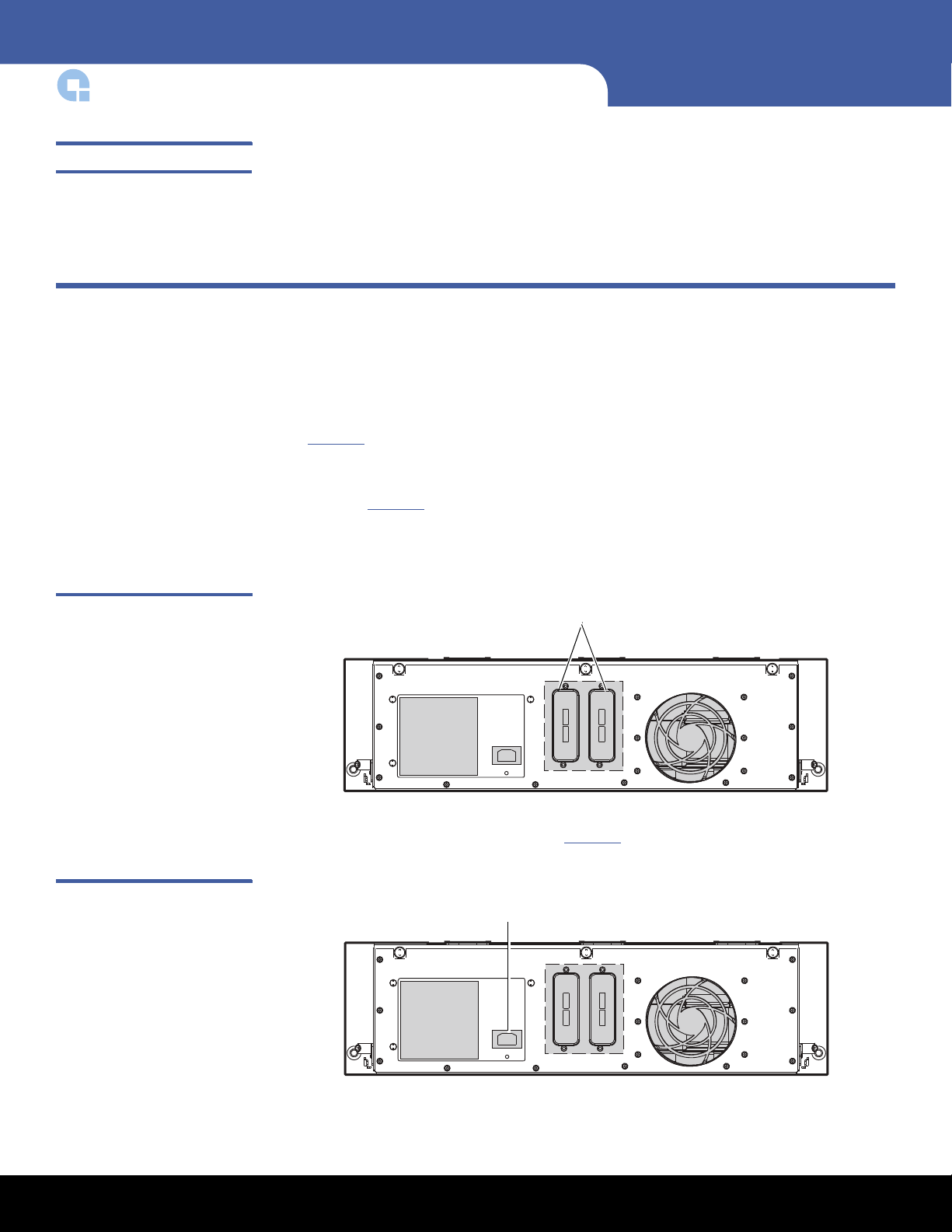
Connecting the Drive Interface and Power Cables
1 Shut down and turn off the host server system.
2 T
urn off all attached accessory devices, such as printers and other SCSI devices.
Figure 1 SAS Interface
Connectors
3 On th
4 Connect the supplied AC power cable to the AC power connector on the back panel
e back panel of a serial-attached SCSI (SAS) 3U Rackmount enclosure (see
Figure
of the 3U Rackmount enclosure (see Figure
1):
a Connect one end of the supplied external SAS interface cable to the external SAS
interface connector on the same side of the enclosure as the installed tape drive
(see Figure 1
b Connect the other end of the external SAS interface cable to the SAS connector
on the host server.
).
2).
Figure 2 AC Power Connector
2 Connecting the Drive Interface and Power Cables
Page 3

Figure 3 Power Button
Power switch
Power LED
LTO-5 Full-Height Tape Drive
5 Connect the other end of the AC power cable to the rack/facility AC power
receptacle.
6 Press the master AC power switch on the front of the 3U Rackmount enclosure to
apply power to the enclosure and illuminate the power LED (see Figure
7 Turn on all attached accessory devices, such as printers and other SCSI devices that
you turned off at step 2 of this procedure.
8 T
urn on and restart the host server.
3).
Installing a Second Tape Drive or Replacing a Tape Drive
Follow these instructions to install a second tape drive or to replace a tape drive after it
has been removed.
Caution: Before installing a second tape drive, you must turn off the 3U Rackmount
enclosure and disconnect it from its AC power source.
Preinstallation Requirements
Before installing a second tape drive in the 3U Rackmount enclosure, make sure you
have the following required tools and parts:
To ol s
Parts
#2 Phillips screw driver
• A supported model tape drive
• SAS cable depending on the tape drive type
Installing a Second Tape Drive or Replacing a Tape Drive 3
Page 4

LTO-5 Full-Height Tape Drive
Top panel
Installation Procedure The installation procedure is divided into the following major sections:
Note: The 3U rackmount enclosure is designed for full-height tape drives, however,
half-height tape drives can also be installed. Refer to the tape drive
documentation for information on installation.
• Removing the Top Panel
• Adding a Second Tape Drive
• Replacing a Tape Drive:
• Connecting the Tape Drive Cables
• Closing the Top Panel
Removing the Top Panel
To remove the top panel:
Figure 4 Top Access Panel
1 Press th
turn off the drive power.
2 Disconne
the 3U Rackmount enclosure.
3 Remove the 3U Rackmount enclosure from the equipment rack and place it on a
clean, stable, fl
4 Open
e drive power switch on the front panel of the 3U Rackmount enclosure to
ct the AC power cable from the AC power connector on the back panel of
at surface.
the top access panel (see Figure 4):
4 Installing a Second Tape Drive or Replacing a Tape Drive
Adding a Second Tape Drive
Note: If you are replacing a tape drive, refer to Replacing a Tape Drive: on page 6.
To add a second tape drive:
1 Remove the shipping screw f
rom the drive blank next to the thumbscrew.
Page 5
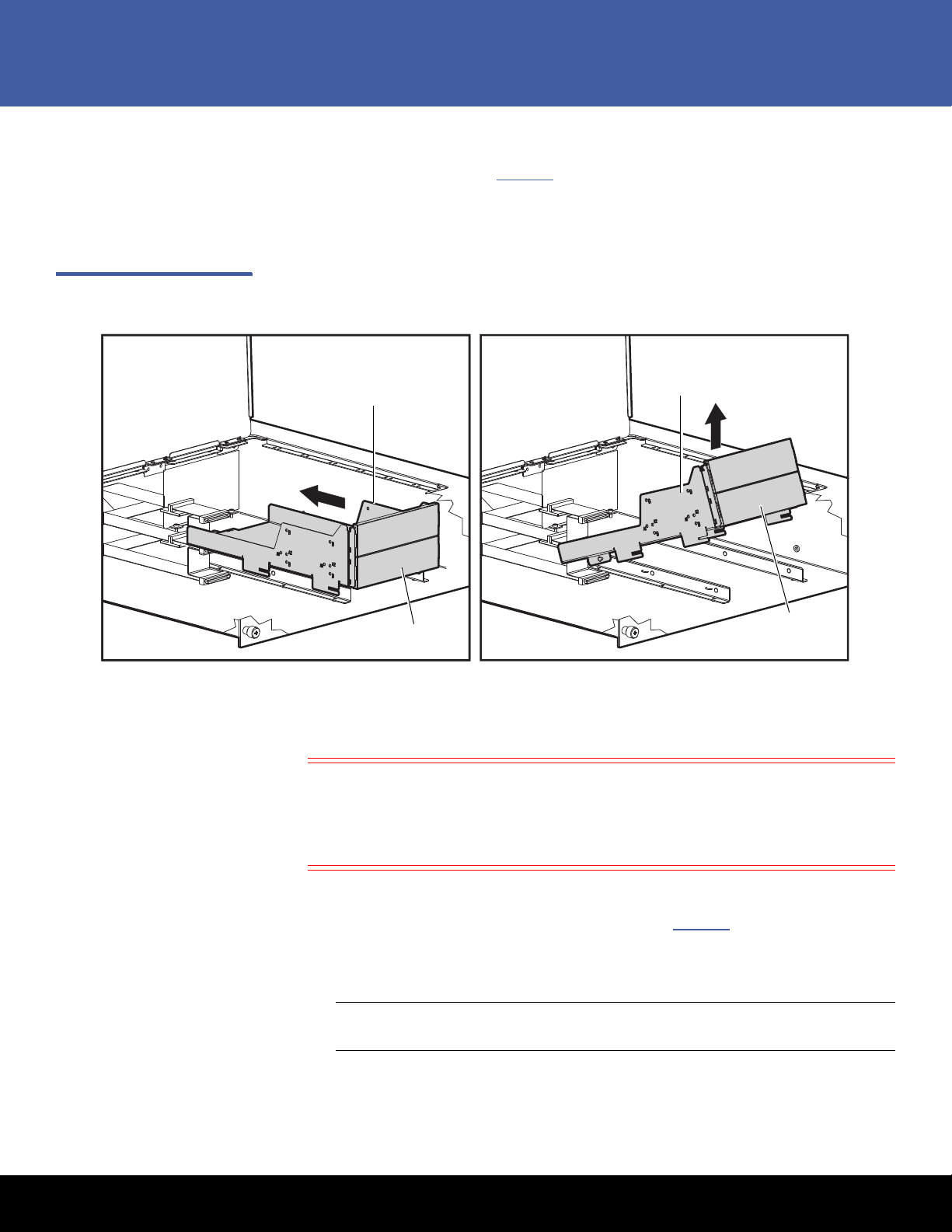
2 Loosen the thumbscrew.
Drive tray
Drive tray
Drive blanks
Drive blanks
3 Remove the drive tray (see Figure 5):
LTO-5 Full-Height Tape Drive
Figure 5 Removing the Drive
Blank
a Push t
he drive tray toward the rear of the 3U enclosure.
b Pull the drive tray up and out at an angle.
4 Remove the drive blanks from the front of the drive tray.
5 P
osition the tape drive in the drive tray and align mounting holes with the holes in
the drive tray.
Caution: If you are installing a half-height tape drive, using screws other than
the Phillips screws labeled as General Mounting Screws can damage
the tape drive.
Do not us
e screws other than the General Mounting Screws to secure
the internal LTO-5 Half-Height Tape Drive.
6 Secure the drive using two screws on each side of the tape drive.
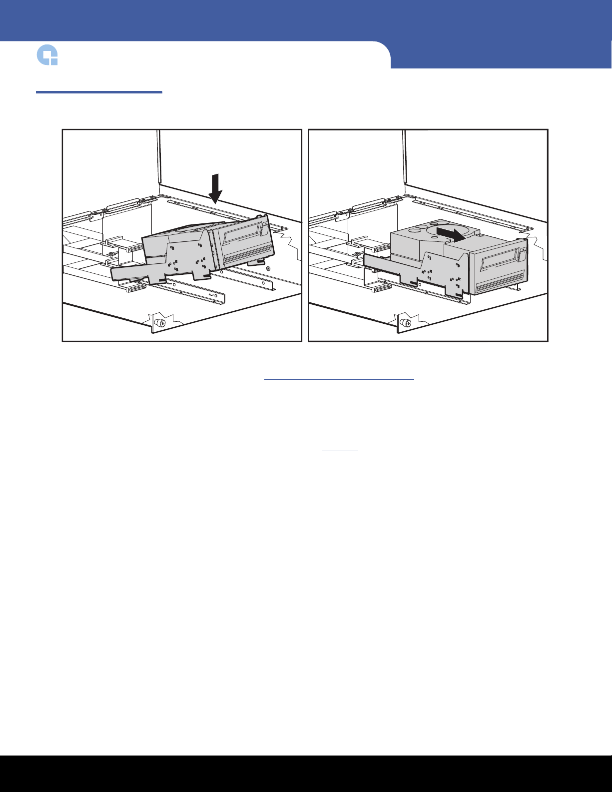
7 In
stall the tape drive tray into the 3U enclosure (see Figure 6):
a Place the drive tray in the enclosure at an angle and then lay it flat.
b Slide the drive toward the front of the enclosure.
Note: Ensure that the cut outs on the drive tray line up with the tabs on the
enclosure.
Installing a Second Tape Drive or Replacing a Tape Drive 5
Page 6
LTO-5 Full-Height Tape Drive
Figure 6 Installing the Tape
Drive
8 Secure the tape drive tray by tightening the thumbscrew.
Continue with
Connecting the Tape Drive Cables on page 8.
Replacing a Tape Drive:
To replace a tape drive:
1 Remove th
a Disconne
a Push the drive tray toward the rear of the 3U enclosure.
b Pull the drive tray up and out at an angle.
e tape drive (see Figure 7):
ct all cables from the tape drive.
6 Installing a Second Tape Drive or Replacing a Tape Drive
Page 7
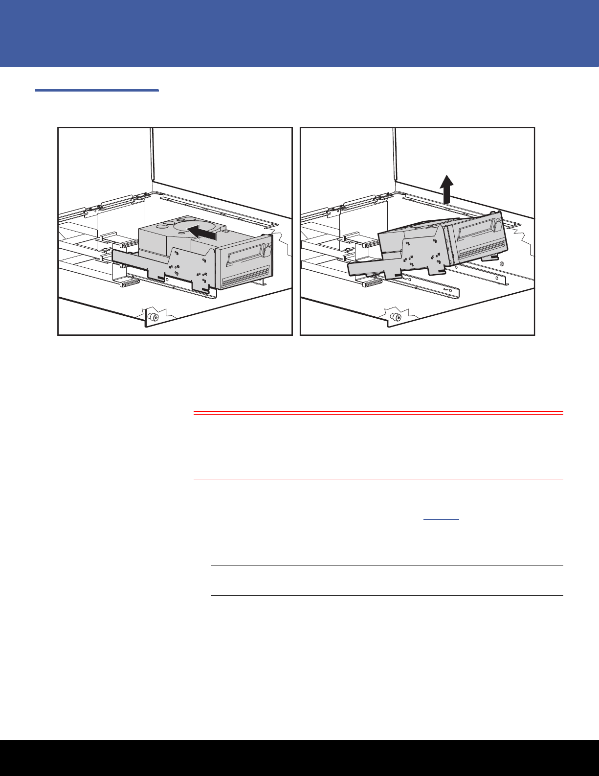
Figure 7 Removing the Tape
Drive
LTO-5 Full-Height Tape Drive
2 Remove the screws securing the mounting drive tray to the tape drive.
3 Re
move the failed tape drive from the drive tray.
4 P
osition the new tape drive in the drive tray and align mounting holes with the holes
in the drive tray.
Caution: If you are installing a half-height tape drive, using screws other than
the Phillips screws labeled as General Mounting Screws can damage
the tape drive.
Do not us
e screws other than the General Mounting Screws to secure
the internal LTO-5 Half-Height Tape Drive.
5 Secure the drive using two screws on each side of the tape drive.
6 In
stall the tape drive tray into the 3U enclosure (see Figure 8):
a Place the drive tray in the enclosure at an angle and then lay it flat.
b Slide the drive toward the front of the enclosure.
Note: Ensure that the cut outs on the drive tray line up with the tabs on the
enclosure.
Installing a Second Tape Drive or Replacing a Tape Drive 7
Page 8

LTO-5 Full-Height Tape Drive
SAS cable
Power cable
Figure 8 Installing the New
Ta p e D r i v e
Figure 9 Connecting the SAS
and Power Cables
7 Secure the tape drive tray by tightening the thumbscrew.
Continue with
Connecting the Tape Drive Cables on page 8.
Connecting the Tape Drive Cables
To connect the tape drive cables:
1 Conne
ct the following cables to the back of the tape drive (see Figure 9).
a Connect the SAS cable
to the tape drive SAS connector.
b Connect a power cable to the SAS cable.
8 Installing a Second Tape Drive or Replacing a Tape Drive
Page 9
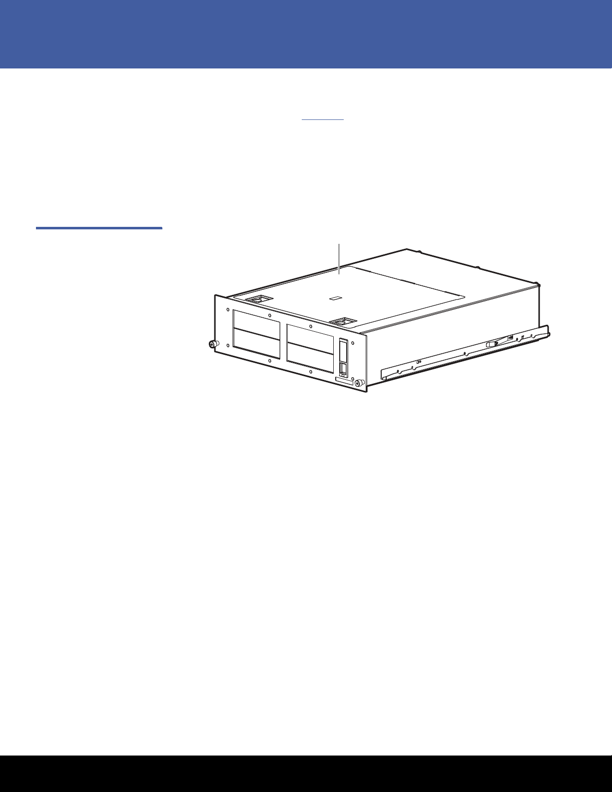
Figure 10 Closing the Top
Top panel
Access Panel
LTO-5 Full-Height Tape Drive
Closing the Top Panel
To close the top panel (see Figure 10):
1 Close the top access panel.
2 Install the 3U enclosure back into the rack.
3 Connect the AC power connector on the back panel of the 3U Rackmount enclosure.
4 Press the drive power switch on the front panel of the 3U Rackmount enclosure to
turn on the drive power.
Installing a Second Tape Drive or Replacing a Tape Drive 9
Page 10

LTO-5 Full-Height Tape Drive
Installing the 3U Rackmount Enclosure in a Rack
The rack rails supplied with the 3U rackmount enclosure can be used to install the unit in
racks that have round, square, or threaded holes in the vertical mounting bars.
The kit contains the following items:
• A template to mark the rack for proper alignment of rack-mounting brackets.
• A cable management system consisting of a cable reel and cable rack bracket.
• A pair of spring-loaded rails.
Tools Required If you are installing the tape enclosure in a rack with unmarked holes in the vertical
mounting bars the following items will make the rack installation easier:
•Pencil
• #2 Phillips screwdriver to install the cable management system.
• Two M6 x 1.0-12L Phillips screws that came with your rack.
Installation Requirements
When installing the enclosure in a rack:
• Start at the bottom of the rack, or at the top of a previously mounted component,
and work upward.
• If possible, install the heaviest components at the bottom and lighter ones toward
the top of the rack.
• Make sure that the rack-mounting rails are level from front to back.
WARNING: To reduce the risk of personal injury or equipment damage, be sure that:
1. The rack leveling jacks are extended to the floor. 2. The full weight of
the rack rests on the leveling jacks. 3. The stabilizing feet are attached to
the rack if it is a single rack installation. 4. The racks are coupled in
multiple rack installations. 5. Only one component is extended at a time.
6. A rack may become unstable if more than one component is extended
for any reason.
Before you begin
If you are installing the 3U rackmount enclosure in a rack with unmarked holes in the
vertical mounting bars, identify and mark the correct mounting holes in the rack before
you begin rail installation.
10 Installing the 3U Rackmount Enclosure in a Rack
Page 11
LTO-5 Full-Height Tape Drive
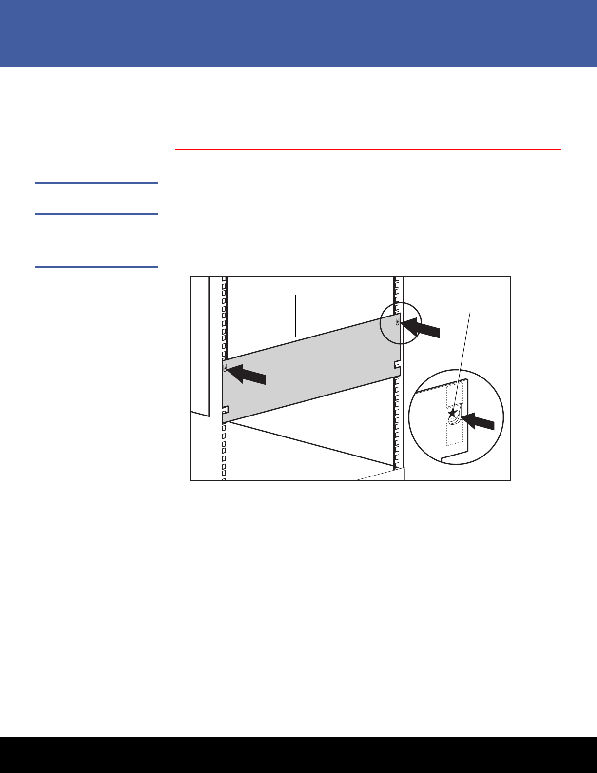
Mark with pencil
Te mp l at e
Caution: It is important to install rack components level. To ensure that the 3U
rackmount enclosure is installed correctly it may be necessary to measure
the height of the correct mounting holes in the front and rear vertical
mounting bars.
Installing the 3U Enclosure
Figure 11 Attaching the
Template to the Rack
To install the 3U enclosure:
1 Attach the template to the front of t
2 Usi
ng a pencil, mark the holes for the front tabs of the spring-loaded rack rails, and
he rack (see Figure 11).
mark the top and bottom edges of the template for additional installations.
3 Repeat steps 1 and 2 for the back of the rack.
4 Install
the spring-loaded rack rails (see Figure 12):
a F
rom the back of the rack, insert the front tabs of the spring-laded rack rail into
the proper holes.
b Press the rail forward and insert the rear tabs of the spring-loaded rack rail into
Installing the 3U Rackmount Enclosure in a Rack 11
the proper holes.
c The rail locks into place securely.
Page 12

LTO-5 Full-Height Tape Drive
Back of rack
Front of rack
Cable reel
Figure 12 Attaching the
Spring-loaded Rails
5 Repeat steps 4 and 5 for the second spring-loaded rack rail.
6 F
rom the back of the rack, align the cable reel with the hole in the right spring-
loaded rack rail and secure it with an M6 x 1.0-12L Phillips screw (see Figure
13).
Figure 13 Attaching the
Spring-loaded Rails
7 Tighten the thumbscrew into the spring-loaded rack rail.
8 F
rom the back of the rack, align the cable rack bracket with the hole in the spring-
loaded rack rail and secure it with an M6 x 1.0-12L Phillips screw (see Figure
14).
12 Installing the 3U Rackmount Enclosure in a Rack
Page 13

Figure 14 Attaching the Cable
Cable bracket
3U enclosure
Rack Bracket
LTO-5 Full-Height Tape Drive
9 Tighten the thumbscrew into the spring-loaded rack rail.
Figure 15 Installing the 3U
Enclosure
10 Al
ign the rear of the storage enclosure rails with the front end of the spring-loaded
rack rails, then push it fully into the rack (see Figure
15).
Caution: Be sure to keep the component parallel to the floor when sliding the
storage enclosure into the spring-loaded rack rails. Tilting the
component up or down could result in damage to the rails.
11 Tighten the front panel thumbscrews.
Installing the 3U Rackmount Enclosure in a Rack 13
Page 14

LTO-5 Full-Height Tape Drive
Cable reel
Cable bracket
12 Connect a SAS cable to the back of the 3U enclosure (see Figure 1 on page 2) for
every SAS device in the 3U enclosure.
Figure 16 Securing the System
Cables
13 Conne
14 Secure
ct the power cable to the back of the 3U enclosure (see Figure 2 on page 2).
the system cables at the back of the 3U enclosure to the cable reel and cable
bracket as shown in Figure
16.
The 3U rackmount enclosure installation is complete.
14 Installing the 3U Rackmount Enclosure in a Rack
Page 15

Class A Device Declarations
WARNING: This equipment has been tested and found to comply with the limits for a
Class A digital device pursuant to Part 15 of the FCC Rules. These limits are
designed to provide reasonable protection against harmful interference
when the equipment is operated in a commercial environment. This
equipment generates, uses, and can radiate radio frequency energy and,
if not installed and used in accordance with the instruction's manual,
might cause interference to radio communications. Operation of this
equipment in a residential area is likely to cause interference, in which
case users are required to correct the interference at their expense.
The user is cautioned that changes and modifications made to the
equipment without approval of the manufacturer could void the user's
authority to operate this equipment.
LTO-5 Full-Height Tape Drive
Class A Device Declarations 15
Page 16

Backup. Recovery. Archive. It’s What We Do.
©2010 Quantum Corporation. All rights reserved. Quantum, the Quantum logo, and all
other logos are registered trademarks of Quantum Corporation or of their respective owners.
Protected by Pending and Issued U.S. and Foreign Patents, including U.S. Patent No. 5,990,810.
For assistance, contact the Quantum Customer Support Center:
USA: 800-284-5101 (toll free) or 949-725-2100
EMEA: 00800-4-782-6886 (toll free) or +49 6131 3241 1164
APAC: +800 7826 8887 (toll free) or +603 7953 3010
Worldwide: http://www.quantum.com/ServiceandSupport
About Quantum
Quantum Corp. (NYSE:QTM) is the leading global storage company
specializing in backup, recovery and archive. Combining focused
expertise, customer-driven innovation, and platform independence,
Quantum provides a comprehensive range of disk, tape, media and
software solutions supported by a world-class sales and service
organization. This includes the DXi™-Series, the first disk backup
solutions to extend the power of data deduplication and replication
across the distributed enterprise. As a long-standing and trusted
partner, the company works closely with a broad network of
resellers, OEMs and other suppliers to meet customers’ evolving
data protection needs.
LTO-5 Full-Height Tape Drive
*6-66885-01*
16 6-66885-01 Rev A, March 2010
 Loading...