

Page 1
1U Rackmount
Quick Start Guide
CONTENTS
English ................................1
German ...............................6
Spanish ..............................11
French ................................16
Japanese ...........................21
Korean ...............................26
Simplified Chinese ............31
Class A Device
Declarations ......................36
For More Information .......36
Introduction 0
This guide provides instructions for installing the 1U Rackmount enclosure in an
equipment rack, and for installing tape drives into the 1U Rackmount.
The 1U Rackmount accommodates the following tape drives:
• DAT-72 (models CD72 and CD144)
• DLT-V4 (models CV1303 and CV1304)
• DLT VS160 (models BHFCA-EO, BHFCA-EY, BHGCA-EO and BHGCA-EY)
• LTO-2 HH (models CL1003 and CL1004)
• LTO-3 HH (models TC-L33CX-EO and TC-L33CX-EY)
Power requirements for the 1U Rackmount are as follows:
• 100-240 Volts AC / 4-2 Amps
• 47-63 Hz
The 1U Rackmount comes with either one or two tape drives installed. If yours
came with one, you may add another in the future (you may use any of the abovementioned tape drive types). See Installing a Second Tape Drive
for instructions.
Installing the 1U Rackmount in an Equipment Rack 0
1 The packing box contains the 1U Rackmount enclosure, mounting kit, and
accessories.
2 Use the mounting kit to install the 1U Rackmount into your equipment rack.
Refer to the installation instructions included with mounting kit.
ARNING: For maximum stability, the equipment rack should be securely bolted
W
to the floor per the rack manufacturer’s recommendations.
After installing components in the equipment rack, do not pull out more
than one component on its slide rails at a time. If the equipment rack is not
securely bolted to the floor, the weight of more than one extended
component could cause the equipment rack to become unstable, tip over,
and cause damage, serious bodily injury, or death.
Page 2
1U Rackmount Quick Start Guide
Connecting the SCSI and Power Cables0
1 Shut down and turn off the selected host server. Turn
off all attached accessory devices, such as printers and
other SCSI devices.
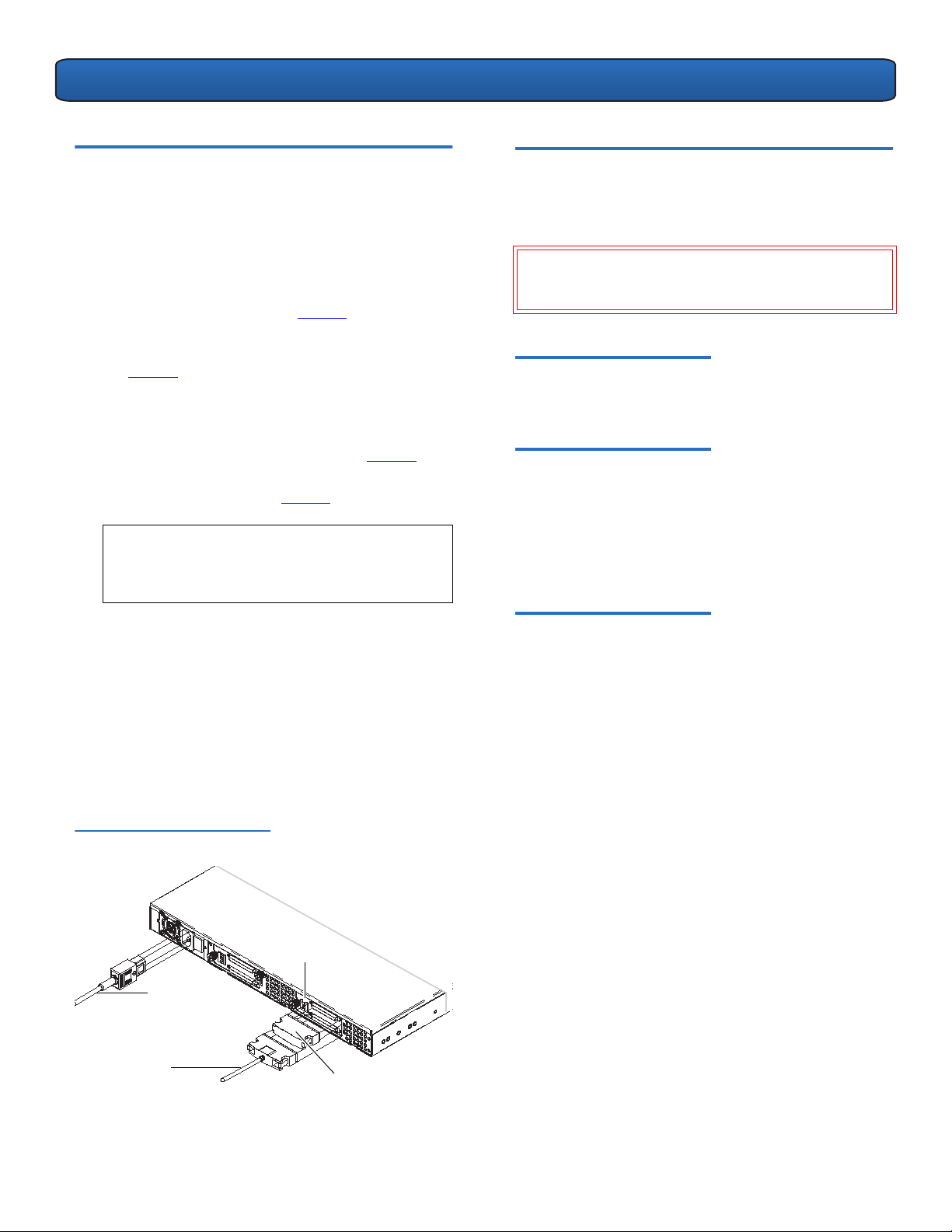
2 On the back panel of the 1U Rackmount, connect one
end of the supplied external SCSI cable to either of the
SCSI connectors on the same side of the 1U Rackmount
as the installed tape drive. See figure 1
3 Connect the supplied SCSI terminator to the adjacent
SCSI connector on the back panel of the 1U Rackmount.
See figure 1
4 Connect the other end of the external SCSI cable to the
host.
5 Connect the power cable to the power receptacle on
the back panel of the 1U Rackmount. See figure 1.
6 Each SCSI device must have its own unique ID. Change
the SCSI ID if necessary. See figure 1.
OTE: Any time you change the SCSI ID, you must
N
.
turn the tape drive power off and then back on
by pressing the power button on the front panel
of the 1U Rackmount.
.
Installing a Second Tape Drive 0
Follow these instructions to install a second tape drive or to
reinstall a tape drive after it has been removed.
CAUTION: Before performing this procedure, you must
turn off the 1U Rackmount and disconnect it from its
power source.
Required Tools 0
#1 and #2 PHILLIPS® screwdrivers
Additional Required Equipment 0
• (1) Tape drive
• (1) External SCSI cable
• (1) SCSI terminator
7 Plug in the power cable to the nearest properly
grounded power outlet.
8 Turn on the power switch on the back panel of the
1U Rackmount.
9 Turn on drive power by pressing the power button on
the front panel of the 1U Rackmount. The green power
LED should illuminate.
10 Turn on any other devices you turned off earlier.
11 Turn on the host server.
Figure 1 Back Panel
Configuration
SCSI ID
switch
Power
cable
SCSI cable
SCSI
Terminator
Instructions 0
1 Turn off 1U Rackmount drive power by pressing the
power button on the front panel.
2 Turn off the power switch on the back panel of the 1U
Rackmount.
3 Disconnect the power cable from the back panel of the
1U Rackmount.
4 Remove the 1U Rackmount from the the equipment
rack. Place the 1U Rackmount on a clean, stable, flat
surface.
2
Page 3

1U Rackmount Quick Start Guide
''6
5 Loosen the captive thumbscrew securing the top cover
(thumbscrew is located on back panel). Slide the cover
toward the back of the 1U Rackmount about 1/2 inch
to loosen it from the front clips. Lift the top cover off.
See figure 2
.
Figure 2 Removing the Top Cover
Top c o v e r
thumbscrew
6 Inside the chassis, remove the two screws securing the
front filler panel to the 1U Rackmount walls using a
#2 PHILLIPS screwdriver. Lift out the filler panel and
discard. See figure 3
.
7 Remove the foam insert from the bulkhead. See
figure 3.
8 Remove the two mounting bracket screws using a
#1 PHILLIPS screwdriver. Lift off the mounting brackets.
See figure 3
.
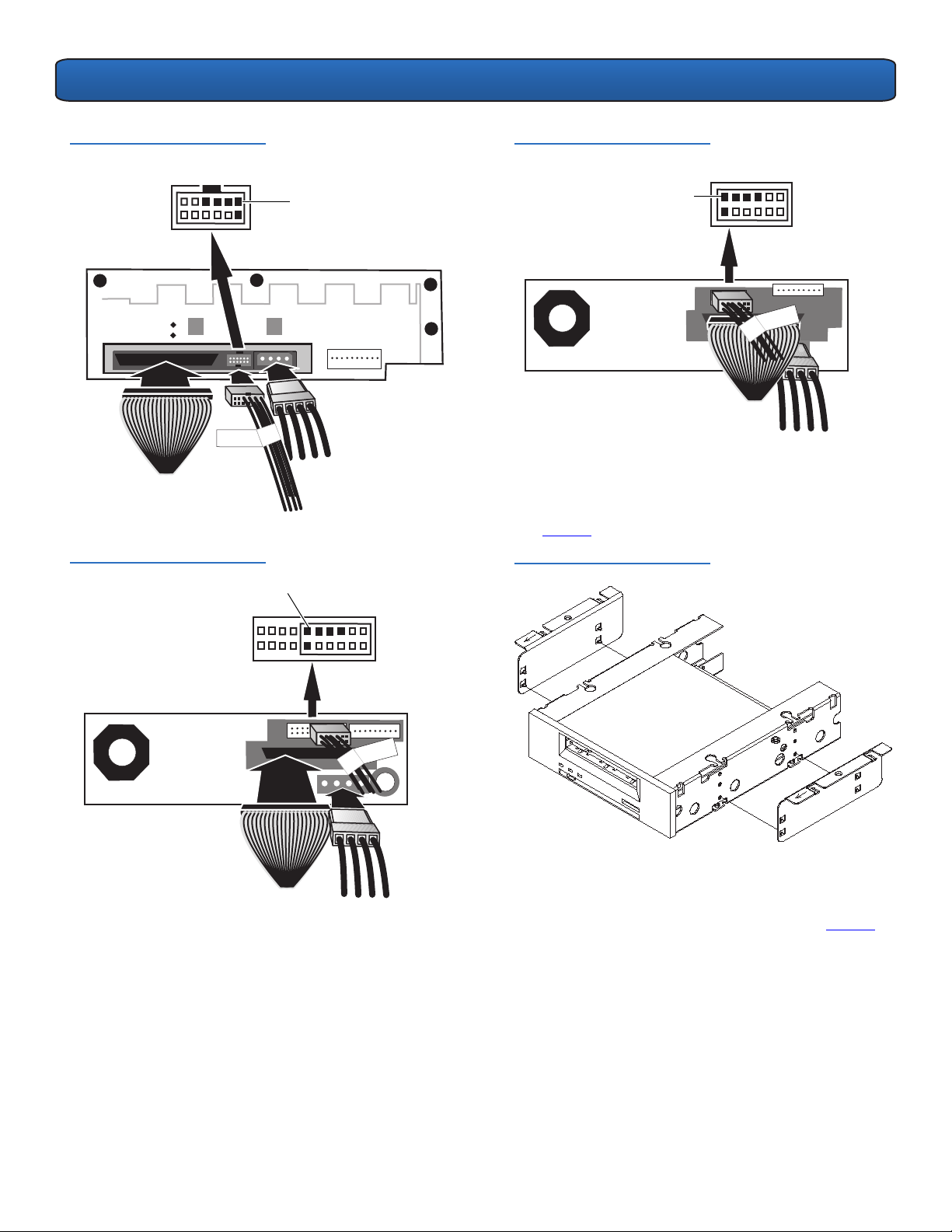
9 Connect the internal SCSI cable, SCSI ID cable, and
power cable to the back of the second tape drive.
Follow these specific instructions for your tape drive:
• DAT 72, DLT-V4, and DLT VS160: Use the keyed
SCSI ID connector labeled “DDS”. The purple wire
on the SCSI ID cable must be connected to the
upper right SCSI ID pin. See figure 4
and figure 5.
• LTO-2 HH: Use the SCSI ID cable labeled “LTO”.
Connect the SCSI ID cable to the 12 right-most
pins. (The eight left-most pins are not used.) The
purple wire must be in the upper left position. See
figure 6
.
• LTO-3 HH: Use the SCSI ID cable labeled “LTO”. The
purple wire must be in the upper left position. See
figure 7
.
Figure 4 DAT 72 Connections
Purple wire
location
Figure 3 Items Inside Chassis
Filler panel
screw
Mounting
brackets
Filler panel
Foam
insert
Mounting
bracket
screws
3
Page 4
1U Rackmount Quick Start Guide
''6
/72
/72
/+
Figure 5 DLT VS160 and DLT-V4
Connections
Figure 6 LTO-2 HH Connections
Purple wire location
Purple wire
location
Figure 7 LTO-3 HH Connections
Purple wire
location
10 Insert the two posts on each mounting bracket into the
mounting holes on either side of the second tape drive.
In tape drives with four mounting holes, insert the
posts into the lower set of mounting holes. See
figure 8
.
Figure 8 Mounting Brackets
11 While holding the mounting brackets against the tape
drive, position the tabs of the mounting brackets over
the retaining holes in the tape drive bay. See figure 9
.
4
Page 5

1U Rackmount Quick Start Guide
Figure 9 Aligning Tape Drive
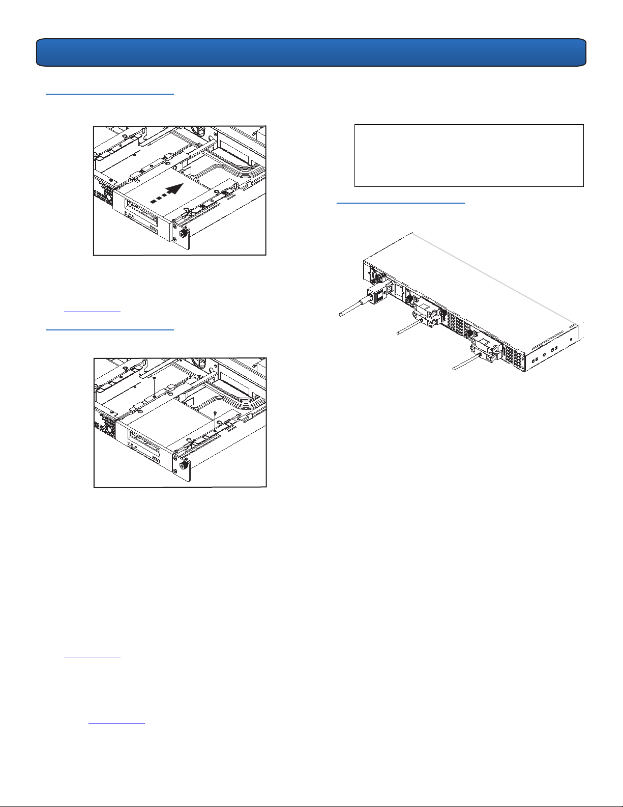
12 Lower the second tape drive into the tape drive bay.
Slide the tape drive toward the back of the
1U Rackmount until the front of the tape drive is flush
with the front panel of the 1U Rackmount and the tabs
on the mounting brackets slide into the retaining holes
on either side of the tape drive bay. See figure 10
.
Figure 10 Sliding Tape Drive
14 Replace the 1U Rackmount top cover and tighten the
top cover thumbscrew.
15 Reinstall the 1U Rackmount into the equipment rack.
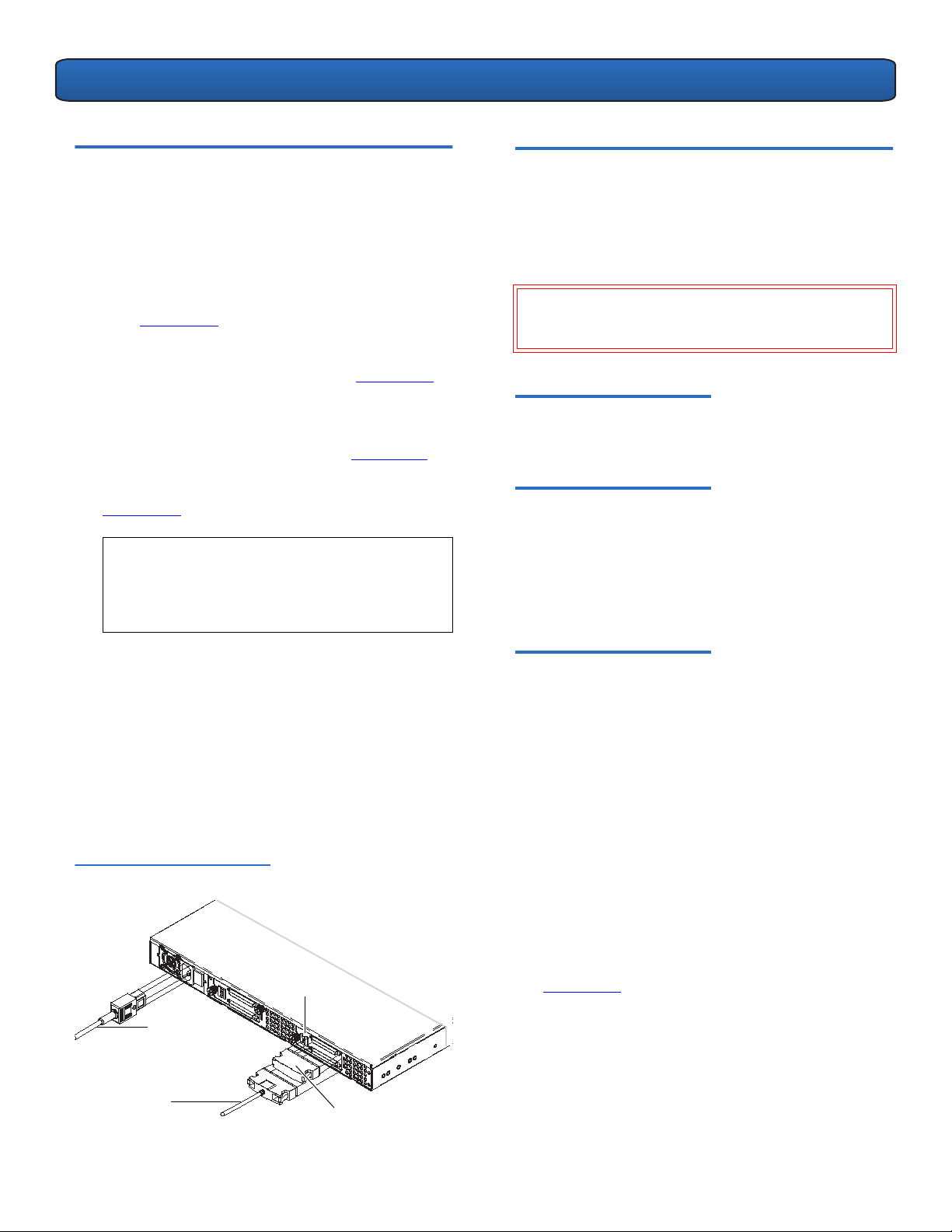
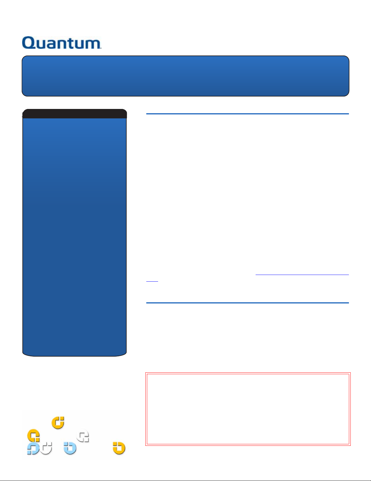
16 On the back panel of the 1U Rackmount, connect one
end of an external SCSI cable to either of the SCSI
connectors on the same side of the 1U Rackmount as
the second tape drive.
17 Connect a SCSI terminator to the adjacent SCSI
connector. See figure 12
.
18 Connect the other end of the SCSI cable to the host.
19 Reconnect the power cable to the power receptacle on
the back panel of the 1U Rackmount. See figure 12
.
20 Each SCSI device must have its own unique ID. Change
the SCSI ID if necessary.
N
OTE: Any time you change the SCSI ID, you must
turn the tape drive power off and then back on
by pressing the power button on the front panel
of the 1U Rackmount.
Figure 12 Completed Back Panel
13 Reinstall the two mounting bracket screws using a
#1 PHILLIPS screwdriver. See figure 11
.
Figure 11 Reinstalling Mounting
Bracket Screws
21 Turn on the power switch on the back panel of the 1U
Rackmount.
22 Turn on drive power by pressing the power button on
the front panel of the 1U Rackmount.
5
Page 6

1U Rackmount
Kurzanleitung
INHALT
Englisch ............................... 1
Deutsch................................6
Spanisch.............................11
Französisch ........................16
Japanisch ...........................21
Koreanisch .........................26
Vereinfachtes Chinesisch ..31
Gerät der Klasse A
Deklarationen....................36
Weitere Informationen .....36
Einführung 0
Dieses Handbuch enthält Anleitungen zur Installation eines 1U RackmountGehäuses in ein Geräte-Rack und zur Installation von Bandlaufwerken in das 1U
Rackmount.
Die folgenden Bandlaufwerke können in das 1U Rackmount eingebaut werden:
• DAT-72 (Modelle CD72 und CD144)
• DLT-V4 (Modelle CV1303 und CV1304)
• DLT VS160 (Modelle BHFCA-EO, BHFCA-EY, BHGCA-EO und BHGCA-EY)
• LTO-2 HH (Modelle CL1003 und CL1004)
• LTO-3 HH (Modelle TC-L33CX-EO und TC-L33CX-EY)
Das 1U Rackmount erfordert die folgenden Leistungsparameter:
• 100-240 Volt Wechselstrom / 4-2 Ampere
• 47-63 Hz
Das 1U Rackmount wird entweder mit einem oder mit zwei installierten
Bandlaufwerken geliefert. Wenn Ihr Modell mit einem Bandlaufwerk ausgestattet
ist, können Sie zu einem späteren Zeitpunkt ein weiteres installieren (Sie können
einen beliebigen der oben erwähnten Bandlaufwerktypen einsetzen). Anleitungen
hierzu erhalten Sie unter Installation eines zweiten Bandlaufwerks
.
Installation des 1U Rackmount in ein Geräte-Rack 0
1 Die Verpackungskiste enthält das 1U Rackmount-Gehäuse, Montage-Kit und
Zubehör.
2 Verwenden Sie das Montage-Kit zur Installation des 1U Rackmount in Ihrem
Geräte-Rack. Lesen Sie die mit dem Montage-Kit gelieferten
Installationsanleitungen.
ARNUNG: Um maximale Stabilität zu erreichen, sollte das Geräte-Rack gemäß
W
den Empfehlungen des Rack-Herstellers fest in den Boden geschraubt
werden.
Nach der Installation der Komponenten in das Geräte-Rack sollten Sie nicht
mehr als jeweils eine Komponente auf den Laufschienen herausziehen.
Wenn das Geräte-Rack nicht sicher in den Boden geschraubt ist, könnte das
Gewicht von mehr als einer herausgezogenen Komponente verursachen,
dass das Geräte-Rack unstabil wird, umkippt und Schaden, schwere
Körperverletzung oder Tod zur Folge hat.
Page 7
1U Rackmount Kurzanleitung
Anschluss des SCSI-Kabels und des Netzkabels
1
Fahren Sie den ausgewählten Hostserver herunter und
schalten Sie ihn aus. Schalten Sie alle angeschlossenen
Zubehörgeräte wie Drucker und andere SCSI-Geräte aus.
2 Schließen Sie ein Ende des mitgelieferten externen SCSI-
Kabels an einen der SCSI-Steckverbinder an der
Rückplatte des 1U Rackmount an, an derselben Seite
des 1U Rackmount wie das installierte Bandlaufwerk.
Siehe Abbildung 1
3 Schließen Sie den mitgelieferten SCSI-Terminator an den
danebenliegenden SCSI-Steckverbinder an der
Rückplatte des 1U Rackmount an. Siehe Abbildung 1.
4 Schließen Sie das andere Ende des externen SCSI-Kabels
an den Host an.
5
Schließen Sie das Netzkabel an den Netzanschluss an der
Rückplatte des 1U Rackmount an. Siehe Abbildung 1.
6 Jedes SCSI-Gerät muss eine eindeutige ID besitzen.
Ändern Sie die SCSI-ID, falls erforderlich. Siehe
Abbildung 1.
NMERKUNG: Jedes Mal, wenn Sie die SCSI-ID
A
ändern, muss das Bandlaufwerk mit dem
Netzschalter an der Vorderseite des 1U
Rackmount aus- und wieder eingeschaltet
werden.
.
0
Installation eines zweiten Bandlaufwerks 0
Folgen Sie diesen Anleitungen, um ein zweites
Bandlaufwerk zu installieren oder um ein Bandlaufwerk neu
zu installieren, nachdem dieses entfernt worden war.
V
ORSICHT: Vor dem Ausführen dieses Verfahrens muss
das 1U Rackmount ausgeschaltet und von der
Stromquelle getrennt werden.
Benötigte Werkzeuge 0
Kreuzschlitz-Schraubendreher Größe 1 und 2
Weitere benötigte Gegenstände 0
• (1) Bandlaufwerk
• (1) Externes SCSI-Kabel
• (1) SCSI-Terminator
7 Stecken Sie das Netzkabel in die nächste
ordnungsgemäß geerdete Steckdose.
8 Schalten Sie das 1U Rackmount mit dem Netzschalter
an der Rückplatte des 1U Rackmount ein.
9 Schalten Sie das Laufwerk mit dem Netzschalter an der
Vorderseite des 1U Rackmount ein. Die grüne Netz-LED
sollte aufleuchten.
10 Schalten Sie alle anderen Geräte ein, die Sie
ausgeschaltet hatten.
11 Schalten Sie den Hostserver ein.
Abbildung 1 Konfiguration der
Rückplatte
SCSI-IDSchalter
Netzkabel
SCSI-Kabel
SCSITerminator
Anleitungen 0
1 Schalten Sie das 1U Rackmount-Laufwerk mit dem
Netzschalter an der Vorderseite aus.
2 Schalten Sie das 1U Rackmount mit dem Netzschalter
an der Rückplatte des 1U Rackmount aus.
3 Trennen Sie das Netzkabel von der Rückplatte des
1U Rackmount.
4 Nehmen Sie das 1U Rackmount aus dem Geräte-Rack
heraus. Stellen Sie das 1U Rackmount auf eine saubere,
stabile, ebene Oberfläche.
5 Lösen Sie die unverlierbare Flügelschraube, die die
obere Abdeckung befestigt (die Flügelschraube
befindet sich an der Rückplatte). Schieben Sie die
Abdeckung ungefähr 1 cm in Richtung der Rückseite
des 1U Rackmount, um sie von den Vorderklemmen zu
lösen. Heben Sie die obere Abdeckung ab. Siehe
Abbildung 2
.
7
Page 8

1U Rackmount Kurzanleitung
''6
''6
Abbildung 2 Abnehmen der
oberen Abdeckung
Flügelschraube der
oberen Abdeckung
6 Entfernen Sie mit einem Kreuzschlitz-Schraubendreher
Größe 2 die zwei Schrauben im Gehäuse, die die
Fronteinlageplatte an den 1U Rackmount-Wänden
befestigen. Nehmen Sie die Fronteinlageplatte heraus
und verwerfen Sie diese. Siehe Abbildung 3.
7 Entfernen Sie die Schaumeinlage aus der Trennwand.
Siehe Abbildung 3.
8 Entfernen Sie die zwei Einbauträgerschrauben mit
einem Kreuzschlitzschraubenzieher Größe 1. Heben Sie
die Einbauträger ab. Siehe Abbildung 3.
Kabel muss an den rechten oberen SCSI-IDAnschlussstift angeschlossen werden. Siehe
Abbildung 4 und Abbildung 5.
• LTO-2 HH: Verwenden Sie das mit „LTO“
gekennzeichnete SCSI-ID-Kabel. Schließen Sie das
SCSI-ID-Kabel an die 12 Anschlussstifte ganz außen
rechts an. (Die acht Anschlussstifte ganz außen
links werden nicht gebraucht.) Der violette Draht
muss sich oben links befinden. Siehe Abbildung 6
• LTO-3 HH: Verwenden Sie das mit „LTO“
gekennzeichnete SCSI-ID-Kabel. Der violette Draht
muss sich oben links befinden. Siehe Abbildung 7.
Abbildung 4 DAT 72-Anschlüsse
.
Position des
violetten
Drahts
Abbildung 3 Elemente im
Gehäuse
Einlageplattenschraube
Schaumeinlage
Einbauträger
Einlageplatte
Einbauträgerschrauben
9 Schließen Sie das interne SCSI-Kabel, das SCSI-ID-Kabel
und das Netzkabel an der Rückseite des zweiten
Bandlaufwerks an. Folgen Sie diesen spezifischen
Anleitungen für Ihr Bandlaufwerk:
• DAT 72, DLT-V4 und DLT VS160: Verwenden Sie
den mit „DDS“ gekennzeichneten kodierten SCSIID-Steckverbinder. Der violette Draht am SCSI-ID-
Abbildung 5 DLT VS160- und
DLT-V4-Anschlüsse
Position des
violetten Drahts
8
Page 9

1U Rackmount Kurzanleitung
/72
/72
/+
Abbildung 6 LTO-2 HHAnschlüsse
Position des violetten
Abbildung 7 LTO-3 HHAnschlüsse
Drahts
Abbildung 8 Einbauträger
11 Halten Sie die Einbauträger an das Bandlaufwerk an
und positionieren Sie die Laschen der Einbauträger über
den Sicherungslöchern des Bandlaufwerkschachts.
Siehe Abbildung 9
.
Abbildung 9 Ausrichten des
Bandlaufwerks
Position des
violetten Drahts
12 Schieben Sie das zweite Bandlaufwerk in den
10 Setzen Sie die zwei Stangen an jedem Einbauträger in
die Einbaulöcher zu beiden Seiten des zweiten
Bandlaufwerks ein. Setzen Sie die Stangen bei
Bandlaufwerken mit vier Einbaulöchern in den unteren
Einbaulochsatz ein. Siehe Abbildung 8.
Bandlaufwerkschacht hinein. Schieben Sie das
Bandlaufwerk in Richtung der Rückseite des 1U
Rackmount, bis die Vorderseite des Bandlaufwerks mit
der Vorderseite des 1U Rackmount bündig ist und die
Laschen an den Einbauträgern in die Sicherungslöcher
zu beiden Seiten des Bandlaufwerkschachts gleiten.
Siehe Abbildung 10
.
9
Page 10
1U Rackmount Kurzanleitung
Abbildung 10 Einschieben des
Bandlaufwerks
13 Setzen Sie die zwei Einbauträgerschrauben mit einem
Kreuzschlitzschraubenzieher Größe 1 wieder ein. Siehe
Abbildung 11
.
Abbildung 11 Wiedereinsetzen
der Einbauträgerschrauben
20 Jedes SCSI-Gerät muss eine eindeutige ID besitzen.
Ändern Sie die SCSI-ID, falls erforderlich.
NMERKUNG: Jedes Mal, wenn Sie die SCSI-ID
A
ändern, muss das Bandlaufwerk mit dem
Netzschalter an der Vorderseite des 1U
Rackmount aus- und wieder eingeschaltet
werden.
Abbildung 12 Rückplatte zum
Abschluss des Vorgangs
14 Setzen Sie die obere Abdeckung des 1U Rackmount
wieder auf dieses auf und ziehen Sie die Flügelschraube
der oberen Abdeckung fest.
15 Setzen Sie das 1U Rackmount wieder in das Geräte-
Rack ein.
16 Schließen Sie ein Ende eines externen SCSI-Kabels an
einen der SCSI-Steckverbinder an der Rückplatte des 1U
Rackmount an, an derselben Seite des 1U Rackmount
wie das zweite Bandlaufwerk.
17 Schließen Sie einen SCSI-Terminator an den
danebenliegenden SCSI-Steckverbinder an. Siehe
Abbildung 12
.
18 Schließen Sie das andere Ende des SCSI-Kabels an den
Host an.
19 Schließen Sie das Netzkabel wieder an den
Netzanschluss an der Rückplatte des 1U Rackmount an.
Siehe Abbildung 12
.
21 Schalten Sie das 1U Rackmount mit dem Netzschalter
an der Rückplatte des 1U Rackmount ein.
22 Schalten Sie das Laufwerk mit dem Netzschalter an der
Vorderseite des 1U Rackmount ein.
10
Page 11
1U para montaje en bastidor
Manual de referencia
CONTENIDO
Inglés ...................................1
Alemán.................................6
Español ..............................11
Francés...............................16
Japonés..............................21
Coreano .............................26
Chino simplificado ............31
Dispositivo clase A
Declaraciones ....................36
Para obtener más
información .......................36
Introducción 0
En esta guía se brindan instrucciones para la instalación del gabinete 1U para
montaje en bastidor en el bastidor de un equipo y para la instalación de unidades
de cinta en su interior.
El 1U para montaje en bastidor puede alojar las siguientes unidades de cinta:
• DAT-72 (modelos CD72 y CD144)
• DLT-V4 (modelos CV1303 y CV1304)
• DLT VS160 (modelos BHFCA-EO, BHFCA-EY, BHGCA-EO y BHGCA-EY)
• LTO-2 HH (modelos CL1003 y CL1004)
• LTO-3 HH (modelos TC-L33CX-EO y TC-L33CX-EY)
A continuación se indican los requisitos de alimentación del 1U para montaje en
bastidor:
• 100-240 VCA / 4-2 A
• 47-63 Hz
El 1U para montaje en bastidor se entrega con una o bien dos unidades de cinta
previamente instaladas. Si el suyo sólo cuenta con una unidad de cinta, puede
agregar otra en el futuro (puede utilizar cualquiera de los tipos de unidades de
cinta mencionados anteriormente). Consulte Instalación de una segunda unidad de
cinta para obtener instrucciones.
Cómo instalar el 1U para montaje en bastidor en un bastidor de equipo
1 La caja de embalaje contiene el gabinete del 1U para montaje en bastidor, el
paquete de montaje y los accesorios.
2 Utilice el paquete de montaje para instalar el 1U para montaje en bastidor en
un bastidor de equipo. Consulte las instrucciones de instalación incluidas en el
paquete de montaje.
DVERTENCIA: Para mayor estabilidad, el bastidor del equipo debe estar
A
firmemente atornillado al piso conforme a las recomendaciones del
fabricante del bastidor.
Una vez que los componentes estén instalados en el bastidor del equipo, no
saque más de un componente a la vez por medio de los rieles deslizables.
Cuando el bastidor del equipo no está firmemente atornillado al piso, el
peso de más de un componente saliendo del bastidor puede ocasionar que
éste pierda estabilidad y se caiga, ocasionando lesiones físicas graves o
incluso la muerte.
0
Page 12

1U para montaje en bastidor: Manual de referencia
Conexión de los cables SCSI y de alimentación
1 Cierre y apague el servidor host seleccionado. Apague
todos los dispositivos accesorios conectados, como
impresoras y otros dispositivos SCSI.
2 En el panel posterior del 1U para montaje en bastidor,
conecte un extremo del cable SCSI externo que se
suministra con el equipo a uno de los conectores SCSI
situados en el mismo lado del 1U donde se encuentra
instalada la unidad de cinta. Consulte la figura 1
3
Conecte el terminador SCSI que se suministra con el equipo
al conector SCSI adyacente ubicado en el panel posterior
del 1U para montaje en bastidor. Consulte la figura 1
4 Conecte el otro extremo del cable SCSI externo al host.
5 Conecte el cable de alimentación en el enchufe
correspondiente ubicado en el panel posterior del 1U
para montaje en bastidor. Consulte la figura 1.
6 Cada dispositivo SCSI debe contar con su propio
identificador exclusivo. Modifique el identificador SCSI
de ser necesario. Consulte la figura 1.
OTA: Siempre que cambie el identificador SCSI,
N
deberá apagar la unidad de cinta y volver a
encenderla presionando el botón de encendido
que se encuentra en el panel frontal del 1U para
montaje en bastidor.
.
.
0
Instalación de una segunda unidad de cinta 0
Siga las instrucciones que aparecen a continuación para
instalar una segunda unidad de cinta o volver a instalar la
que extrajo.
P
RECAUCIÓN: Antes de realizar este procedimiento, debe
apagar el 1U para montaje en bastidor y
desconectarlo de la fuente de alimentación.
Herramientas requeridas 0
Destornilladores PHILLIPS® n° 1 y 2
Otros componentes requeridos 0
• (1) Unidad de cinta
• (1) Cable SCSI externo
• (1) Terminador SCSI
7 Enchufe el cable de alimentación al toma corriente con
toma a tierra más cercano.
8 Active el interruptor de encendido situado en el panel
posterior del 1U para montaje en bastidor.
9 Para encender la unidad, presione el botón de
encendido ubicado en el panel frontal del 1U para
montaje en bastidor. El indicador LED de encendido
color verde se deberá iluminar.
10 Encienda los dispositivos que apagó previamente.
11 Encienda el servidor host.
Figura 1 Configuración del
panel posterior
Selector de
identificador SCSI
Cable de
alimentación
Cable SCSI
Terminador
SCSI
Instrucciones 0
1 Apague el 1U para montaje en bastidor presionando el
botón de encendido situado en el panel frontal.
2 Apague el interruptor de encendido ubicado en el panel
posterior del 1U para montaje en bastidor.
3 Desconecte el cable de alimentación del panel posterior
del 1U para montaje en bastidor.
4 Extraiga el 1U para montaje en bastidor del bastidor del
equipo. Coloque el 1U para montaje en bastidor sobre
una superficie plana, limpia y estable.
5 Afloje el tornillo de palometa cautivo que sujeta la
cubierta superior (el tornillo se encuentra ubicado en el
panel posterior). Deslice la cubierta aproximadamente
1,27 cm (1/2 pulgada) hacia la parte posterior del 1U
para montaje en bastidor para desprenderla de los
sujetadores frontales. Levante y retire la cubierta
superior. Consulte la figura 2
.
12
Page 13

1U para montaje en bastidor: Manual de referencia
''6
Figura 2 Desmontaje de la
cubierta superior
Tornillo de
palometa de la
cubierta superior
6 En el interior del chasis, retire los dos tornillos que
sujetan el panel de relleno frontal a las paredes del 1U
para montaje en bastidor por medio de un
destornillador PHILLIPS n° 2. Levante el panel de relleno
y deséchelo. Consulte la figura 3.
7 Retire el separador de espuma plástica del panel
divisorio. Consulte la figura 3.
8 Retire los dos tornillos de los soportes de montaje por
medio de un destornillador PHILLIPS n° 1. Levante y
retire los soportes de montaje. Consulte la figura 3.
9 Conecte el cable SCSI interno, el cable del identificador
SCSI y el cable de alimentación en la parte posterior de
la segunda unidad de cinta. Siga estas instrucciones
específicas de acuerdo con la unidad de cinta que
utiliza:
• DAT 72, DLT-V4 y DLT VS160: utilice el conector
del identificador SCSI codificado que muestra la
etiqueta “DDS”. El cable de color púrpura dentro
del cable del identificador SCSI debe conectarse a
la patilla del identificador SCSI situada en la parte
superior derecha. Consulte la figura 4
y la figura 5.
• LTO-2 HH: utilice el cable del identificador SCSI que
lleva la etiqueta “LTO”. Conecte el cable del
identificador SCSI a las 12 patillas ubicadas en el
extremo derecho. (Las ocho patillas del extremo
izquierdo no se utilizan). El cable de color púrpura
debe estar en la parte superior izquierda. Consulte
la figura 6
.
• LTO-3 HH: utilice el cable del identificador SCSI
que muestra la etiqueta “LTO”. El cable de color
púrpura debe estar en la parte superior izquierda.
Consulte la figura 7
.
Figura 4 Conexiones DAT 72
Ubicación del
cable de color
púrpura
Figura 3 Elementos del interior
del chasis
Tornillo del
panel de
relleno
Soportes
de montaje
Panel de relleno
Tornillos de
soportes de
montaje
Separador
de espuma
plástica
13
Page 14

1U para montaje en bastidor: Manual de referencia
''6
/72
/72
/+
Figura 5 Conexiones DLT VS160 y
DLT-V4
Figura 6 Conexiones LTO-2 HH
Ubicación del cable de
color púrpura
Ubicación del
cable de color
púrpura
Figura 7 Conexiones LTO-3 HH
Ubicación del
cable de color
púrpura
10 Inserte los dos postes de cada soporte de montaje en
los orificios situados a ambos lados de la segunda
unidad de cinta. En las unidades de cinta con cuatro
orificios de montaje, inserte los postes en el grupo de
orificios inferiores. Consulte la figura 8
.
Figura 8 Soportes de montaje
11 Mientras sujeta los soportes de montaje contra la
unidad de cinta, coloque las lengüetas de los soportes
de montaje sobre los orificios de retención en el
alojamiento de la unidad de cinta. Consulte la figura 9
.
14
Page 15

1U para montaje en bastidor: Manual de referencia
Figura 9 Alineación de la unidad de cinta
12
Introduzca la segunda unidad de cinta en el alojamiento.
Deslice la unidad de cinta hacia la parte posterior del
1U para montaje en bastidor, hasta que la parte
delantera de la unidad de cinta se alinee con el panel
frontal del 1U para montaje en bastidor y las lengüetas
de los soportes de montaje se deslicen en los orificios de
retención situados a ambos lados del alojamiento de la
unidad de cinta. Consulte la figura 10
.
Figura 10 Inserción de la unidad de cinta
14 Vuelva a colocar la cubierta superior del 1U para
montaje en bastidor y apriete el tornillo de palometa
que la sujeta.
15 Coloque nuevamente el 1U para montaje en bastidor en
el bastidor del equipo.
16 En el panel posterior del 1U para montaje en bastidor,
conecte un extremo del cable SCSI externo a uno de los
conectores SCSI situados en el mismo lado del 1U para
montaje en bastidor donde se encuentra la segunda
unidad de cinta.
17 Conecte un terminador SCSI al conector SCSI
adyacente. Consulte la figura 12
.
18 Conecte el otro extremo del cable SCSI en el equipo
host.
19 Vuelva a conectar el cable de alimentación en el
enchufe situado en el panel posterior del 1U para
montaje en bastidor. Consulte la figura 12.
20 Cada dispositivo SCSI debe contar con su propio
identificador exclusivo. Modifique el identificador SCSI
de ser necesario.
OTA: Siempre que cambie el identificador SCSI,
N
deberá apagar la unidad de cinta y volver a
encenderla presionando el botón de encendido
que se encuentra en el panel frontal del 1U para
montaje en bastidor.
13 Coloque nuevamente los dos tornillos de los soportes
de montaje por medio de un destornillador PHILLIPS
n° 1. Consulte la figura 11
.
Figura 11 Colocación de los tornillos de
los soportes de montaje
Figura 12 Panel posterior completo
21 Active el interruptor de encendido situado en el panel
posterior del 1U para montaje en bastidor.
22 Para encender la unidad, presione el botón de
encendido ubicado en el panel frontal del 1U para
montaje en bastidor.
15
Page 16

Montage en rack 1U
Guide de démarrage rapide
SOMMAIRE
Anglais .................................1
Allemand .............................6
Espagnol ............................11
Français..............................16
Japonais.............................21
Coréen ...............................26
Chinois simplifié ...............31
Conditions particulières
relatives aux périphériques
de Classe A ........................36
Pour plus d'informations .36
Introduction 0
Ce guide fournit des instructions pour installer une enceinte de montage en rack
1U dans un rack et des lecteurs de bande dans un montage en rack 1U.
Le montage en rack 1U peut contenir les lecteurs de bande suivants :
• DAT-72 (modèles CD72 et CD144)
• DLT-V4 (modèles CV1303 et CV1304)
• DLT VS160 (modèles BHFCA-EO, BHFCA-EY, BHGCA-EO et BHGCA-EY)
• LTO-2 HH (modèles CL1003 et CL1004)
• LTO-3 HH (modèles TC-L33CX-EO et TC-L33CX-EY)
La puissance requise pour le montage en rack 1U est la suivante :
• 100-240 V c.a. / 4-2 A
• 47-63 Hz
Le montage en rack 1U est disponible avec un ou deux lecteurs de bande installés.
Si un seul lecteur est installé, vous pouvez en ajouter un autre par la suite (vous
pouvez utiliser n'importe quel lecteur de bande mentionné ci-dessus). Voir
Installation d'un deuxième lecteur de bande
pour des instructions.
Installation du montage en rack 1U dans un rack 0
1 Le carton d'emballage contient l'enceinte du montage en rack 1U, le kit de
montage et les accessoires.
2 Utilisez le kit de montage pour installer le montage en rack 1U dans votre rack.
Reportez-vous aux instructions d'installation fournies avec le kit de montage.
VERTISSEMENT : Pour un maximum de stabilité, le rack doit être bien fixé au sol
A
à l'aide de boulons selon les recommandations du fabriquant du rack.
Une fois les composants installés dans le rack, ne retirez pas plus d'un
composant à la fois sur les rails à glissières. Si le rack n'est pas rattaché au
sol avec des boulons, le poids de plus d'un composant étendu risquerait de
rendre le rack instable et de le faire chavirer, ce qui pourrait causer des
dommages, des blessures importantes ou même la mort.
Page 17

Montage en rack 1U – Guide de démarrage rapide
Branchement des câbles SCSI et d'alimentation 0
1 Arrêtez et mettez hors tension le serveur hôte
sélectionné. Éteignez tous les périphériques auxiliaires
reliés, comme les imprimantes et les autres
périphériques SCSI.
2 Sur le panneau arrière du montage en rack 1U,
connectez une extrémité du câble SCSI externe fourni à
l'un des connecteurs SCSI qui se trouve du même côté
que le lecteur de bande installé. Voir figure 1
3 Raccordez le terminateur SCSI fourni au connecteur
SCSI contigu sur le panneau arrière du montage en rack
1U. Voir figure 1.
4
Raccordez l'autre extrémité du câble SCSI externe à l'hôte.
5 Raccordez le câble d'alimentation à la prise sur le
panneau arrière du montage en rack 1U. Voir figure 1.
6 Chaque périphérique SCSI doit avoir son propre
numéro d'identification. Changez le numéro
d'identification SCSI si besoin est. Voir figure 1.
EMARQUE : Chaque fois que vous changez le
R
numéro d'identification SCSI, vous devez
éteindre le lecteur de bande puis le rallumer en
appuyant sur le bouton d'alimentation situé sur
le panneau avant du montage en rack 1U.
.
Installation d'un deuxième lecteur de bande 0
Suivez ces instructions pour installer un deuxième lecteur de
bande ou pour réinstaller un lecteur de bande qui a été
retiré.
TTENTION ! Avant d'effectuer cette procédure, mettez le
A
montage en rack 1U hors tension et débranchez-le
de sa source d'alimentation.
Outils requis 0
Tournevis cruciforme no 1 et 2
Autre matériel requis 0
• (1) Lecteur de bande
• (1) Câble SCSI externe
• (1) Terminateur SCSI
7 Branchez le câble d'alimentation dans la prise reliée à la
terre la plus proche.
8 Appuyez sur l'interrupteur d'alimentation situé sur le
panneau arrière du montage en rack 1U pour allumer.
9 Mettez le lecteur sous tension en appuyant pendant
une seconde sur le bouton d'alimentation situé sur le
panneau avant du montage en rack 1U. Le voyant DEL
d'alimentation vert devrait s'allumer.
10 Allumez les autres périphériques que vous aviez éteints
précédemment.
11 Allumez le serveur hôte.
Figure 1 Configuration du panneau arrière
Commutateur de
numéros
d'identification SCSI
Câble
d'alimentation
Câble SCSI
Terminateur
SCSI
Instructions 0
1 Mettez le lecteur dans le montage en rack 1U hors
tension en appuyant pendant une seconde sur le
bouton d'alimentation situé sur le panneau avant.
2 Appuyez sur l'interrupteur d'alimentation situé sur le
panneau arrière du montage en rack 1U pour éteindre.
3 Déconnectez le câble d'alimentation du panneau arrière
du montage en rack 1U.
4 Retirez le montage en rack 1U du rack. Placez le
montage en rack 1U sur une surface plane, stable et
propre.
5 Desserrez la vis à oreilles imperdable qui fixe le panneau
supérieur (la vis se trouve dans le panneau arrière).
Faites glisser le panneau sur environ 1,25 cm vers
l'arrière du montage en rack 1U pour le libérer des
attaches avant. Soulevez le panneau pour le retirer. Voir
figure 2
.
17
Page 18

Montage en rack 1U – Guide de démarrage rapide
''6
Figure 2 Retrait du panneau
supérieur
Vis à oreilles du
panneau supérieur
6 À l'intérieur du châssis, retirez les deux vis qui fixent le
panneau protecteur avant aux parois du montage en
rack 1U à l'aide d'un tournevis cruciforme n
o
2. Soulevez
le panneau protecteur pour le retirer et jetez-le. Voir
figure 3
7
Retirez le morceau de mousse de la cloison. Voir figure 3.
8 Retirez les deux vis des pattes de fixation à l'aide d'un
tournevis cruciforme n
.
o
1. Soulevez les pattes de
fixation pour les retirer. Voir figure 3.
9 Raccordez le câble SCSI interne, le câble d'identification
SCSI et le câble d'alimentation à l'arrière du deuxième
lecteur de bande. Suivez les instructions qui
correspondent à votre lecteur de bande :
• DAT 72, DLT-V4 et DLT VS160 : utilisez le
connecteur d'identification SCSI codé marqué
« DDS ». Le fil violet du câble d'identification SCSI
doit être raccordé à la broche d'identification SCSI
en haut à droite. Voir figure 4
et figure 5.
• LTO-2 HH : utilisez le câble d'identification SCSI
marqué « LTO ». Raccordez le câble d'identification
SCSI aux 12 broches les plus à droite (les 8 broches
les plus à gauche ne sont pas utilisées). Le fil violet
doit être en haut à gauche. Voir figure 6
.
• LTO-3 HH : utilisez le câble d'identification SCSI
marqué « LTO ». Le fil violet doit être en haut à
gauche. Voir figure 7.
Figure 4 Connexions du DAT 72
Emplacement
du fil violet
Figure 3 Éléments à l'intérieur du
châssis
Vis du panneau
protecteur
Pattes de
fixation
Panneau protecteur
Vis des
pattes de
fixation
Morceau
de
mousse
18
Page 19

Montage en rack 1U – Guide de démarrage rapide
''6
/72
/72
/+
Figure 5 Connexions du DLT
VS160 et du DLT-V4
Figure 6 Connexions du LTO-2 HH
Emplacement du fil violet
Emplacement
du fil violet
Figure 7 Connexions du LTO-3 HH
Emplacement
du fil violet
10 Insérez les deux montants de chaque patte de fixation
dans les trous de montage de chaque côté du deuxième
lecteur de bande. Pour les lecteurs de bande avec
quatre trous de montage, insérez les montants dans les
trous de montage inférieurs. Voir figure 8
.
Figure 8 Pattes de fixation
11 Tout en maintenant les pattes de fixation contre le
lecteur de bande, placez les languettes des pattes de
fixation sur les trous de maintien de la baie de lecteur
de bande. Voir figure 9
.
19
Page 20

Montage en rack 1U – Guide de démarrage rapide
Figure 9 Alignement du lecteur
de bande
12
Abaissez le deuxième lecteur de bande dans la baie de
lecteur de bande. Faites glisser le lecteur de bande vers
l'arrière du montage en rack 1U jusqu'à ce que l'avant du
lecteur de bande s'encastre dans le panneau avant du
montage en rack 1U et que les languettes des pattes de
fixation s'insèrent dans les trous de maintien de chaque
côté de la baie de lecteur de bande. Voir figure 10
Figure 10 Insertion du lecteur de bande
14 Remettez en place le panneau supérieur du montage en
rack 1U et serrez la vis à oreilles du panneau supérieur.
15 Réinstallez le montage en rack 1U dans le rack.
16 Sur le panneau arrière du montage en rack 1U,
connectez l'extrémité d'un câble SCSI externe à l'un des
connecteurs SCSI qui se trouve du même côté que le
deuxième lecteur de bande.
17 Raccordez un terminateur SCSI au connecteur SCSI
contigu. Voir figure 12
.
18 Raccordez l'autre extrémité du câble SCSI à l'hôte.
19 Reconnectez le câble d'alimentation dans la prise sur le
panneau arrière du montage en rack 1U. Voir figure 12
.
20 Chaque périphérique SCSI doit avoir son propre
numéro d'identification. Changez le numéro
d'identification SCSI si besoin est.
EMARQUE : Chaque fois que vous changez le
R
numéro d'identification SCSI, vous devez
éteindre le lecteur de bande puis le rallumer en
appuyant sur le bouton d'alimentation situé sur
.
le panneau avant du montage en rack 1U.
Figure 12 Panneau arrière achevé
13 Réinstallez les deux vis des pattes de fixation à l'aide
d'un tournevis cruciforme no 1. Voir figure 11.
Figure 11 Réinstallation des vis
des pattes de fixation
21 Appuyez sur l'interrupteur d'alimentation situé sur le
panneau arrière du montage en rack 1U.
22 Mettez le lecteur sous tension en appuyant pendant
une seconde sur le bouton d'alimentation situé sur le
panneau avant du montage en rack 1U.
20
Page 21

目次
1U ラックマウント
クイック スタート ガイド
はじめに 0
英語........................ 1
ドイツ語.................... 6
スペイン語................. 11
フランス語................. 16
日本語..................... 21
韓国語..................... 26
中国語(簡体字)............ 31
クラス A デバイス
に関する情報............... 36
詳細情報................... 36
このガイドでは、1U ラックマウント エンクロージャを装置ラックに取り付ける手
順と、1U ラックマウントにテープ ドライブを装着する手順を説明します。
1U ラックマウントには、以下に示すテープ ドライブを収容することができます。
・ DAT-72 ( モデル CD72 および CD144)
・ DLT-V4 ( モデル CV1303 および CV1304)
・ DLT VS160 ( モデル BHFCA-EO、BHFCA-EY、BHGCA-EO および BHGCA-EY)
・ LTO-2 HH ( モデル CL1003 および CL1004)
・ LTO-3 HH ( モデル TC-L33CX-EO および TC-L33CX-EY)
1U ラックマウントに関する電源要件を以下に示します。
・ 100-240 V AC / 4-2 A
・ 47-63 Hz
1U ラックマウントには、テープ ドライブが 1 つまたは 2 つ搭載されています。
テープ ドライブが 1 つしか搭載されていない場合は、将来もう 1 つドライブを
追加することができます。( 上記のテープ ドライブなら、どれを使用しても構い
ません。) 手順については、追加テープ ドライブの取り付け
を参照してください。
装置ラックへの 1U ラックマウントの取り付け 0
1 パッケージの箱には、1U ラックマウント エンクロージャ、取り付けキット、
および付属品が入っています。
2 取り付けキットを使用して 1U ラックマウントを装置ラックに取り付けます。
取り付けキットに同梱の説明書を参照してください。
警告: 最大限の安定性を確保するため、装置ラックは製造元の推奨に従って、
ボルトで床にしっかりと固定してください。
装置ラックにコンポーネントを取り付けたあとで、スライド レール上のコ
ンポーネントを 一度に複数引き出すことは避けてください。 装置ラックが
ボルトで床にしっかりと固定されていない場合に、引き出した複数のコン
ポーネントの重量でラックが不安定になって倒れ、装置の損傷や人身事故
につながる危険性があります。
Page 22

1U ラックマウント クイック スタート ガイド
SCSI と電源ケーブルの接続 0
1 ホスト サーバーをシャットダウンして電源を切ります。
プリンタやその他の SCSI デバイスなど、接続している
付属デバイスの電源をすべて切ります。
2 1U ラックマウントの背面パネル上で、付属の外部 SCSI
ケーブルの一端を、搭載されているテープ ドライブと
同じ側にある 1U ラックマウント側面の、SCSI コネク
タのどちらか 1 つに接続します。図 1
さい。
3 1U ラックマウント背面パネル上にある隣接 SCSI コネ
クタに、付属の SCSI ターミネータを接続します。 図 1
を参照してください。
4
外部 SCSI ケーブルのもう一方の端をホストに接続します。
5 1U ラックマウントの背面パネル上にある電源コンセン
トに電源ケーブルを接続します。図 1 を参照してくだ
さい。
6 各 SCSI デバイスには、それぞれ固有の ID が必要で
す。 必要に応じて SCSI ID を変更してください。 図 1
を参照してください。
注: SCSI ID を変更するときは、1U ラックマウント
の前面パネル上にある電源ボタンを使用して、
テープ ドライブの電源をいったん切ってから入
れ直す必要があります。
7 近くのアース付きコンセントに電源ケーブルを差し込み
ます。
8 1U ラックマウントの背面パネル上にある電源スイッチ
を入れます。
9 1U ラックマウントの前面パネル上にある電源ボタンを
押してドライブの電源を入れます。 緑の電源 LED が点
灯します。
10 先に電源を切っておいたその他のデバイスすべてに電源
を入れます。
11 ホスト サーバーをオンにします。
を参照してくだ
追加テープ ドライブの取り付け 0
追加のテープ ドライブを取り付ける場合、または以前に取
り外したテープ ドライブを再び取り付ける場合は、以下の
手順に従ってください。
注意: この手順を開始する前に、1 U ラックマウントを
オフにし、電源装置から切り離す必要があります。
必要な工具 0
#1 および #2 PHILLIPS® ドライバ
その他に必要な装置 0
・ (1) テープ ドライブ
・ (1) 外部 SCSI ケーブル
・ (1) SCSI ターミネータ
手順 0
1 前面パネル上にある電源ボタンを押して、1U ラックマ
ウント ドライブの電源を切ります。
2 1U ラックマウントの背面パネル上にある電源スイッチ
を切ります。
3 1U ラックマウントの背面パネルから電源ケーブルを外
します。
4 1U ラックマウントを装置ラックから取り外します。 1U
ラックマウントを清潔で、安定した平面上に置きます。
図 1 背面パネルの構成
電源ケーブル
SCSI ケーブル
SCSI ID スイッチ
SCSI ターミネータ
22
Page 23

1U ラックマウント クイック スタート ガイド
''6
5 上面カバーを固定している蝶ねじを緩めます (つまみね
じは、背面パネル上にあります )。 1U ラックマウント
の背面方向にカバーを約 1 cm スライドさせ、前面のク
リップから外します。上面カバーを持ち上げて外しま
す。図 2
を参照してください。
図 2 上部カバーの取り外し
上面カバーの
つまみねじ
6 #2 PHILLIPS ドライバを使用して、シャーシ内部で 1U
ラックマウントの壁に前面フィラー パネルを固定して
いる 2 つのねじを取り外します。フィラー パネルを取
り外し、廃棄します。図 3 を参照してください。
7 隔壁から発泡剤を取り除きます。図 3
を参照してくだ
さい。
8 #1 PHILLIPS ドライバを使用して、2 つの取り付けブラ
ケットねじを外します。取り付けブラケットを外しま
す。図 3 を参照してください。
9 内部 SCSI ケーブル、SCSI ID ケーブル、および電源
ケーブルを追加テープ ドライブの背面に接続します。
お使いのテープ ドライブに特定の手順に従います。
・ DAT 72、DLT-V4、および DLT VS160:「DDS」とラベ
ルのついたキー付き SCSI ID を使用します。SCSI
ID ケーブル上にある紫色のワイヤーを、右上の
SCSI ID ピンに接続します。図 4
および 図 5 を参
照してください。
・ LTO-2 HH:「LTO」とラベルの付いた SCSI ID ケー
ブルを使用します。SCSI ID ケーブルを最右端の
12 のピンに接続します。( 最左端の 8 つのピンは
使用しません。) 紫色のワイヤーは、左上に位置す
る必要があります。図 6
を参照してください。
・ LTO-3 HH:「LTO」とラベルの付いた SCSI ID ケー
ブルを使用します。 紫色のワイヤーは、左上に位置
する必要があります。 図 7 を参照してください。
図 4 DAT 72 の接続
紫色の
ワイヤーの
場所
図 3 シャーシの内容物
フィラー
パネルねじ
取り付けブラケット
フィラー パネル
発泡剤
取り付け
ブラケットねじ
23
Page 24

1U ラックマウント クイック スタート ガイド
''6
/72
/72
/+
図 5 DLT VS160 および DLT-V4
の接続
図 6 LTO-2 HH の接続
紫色のワイヤーの場所
紫色のワイヤーの
場所
図 7 LTO-3 HH の接続
紫色のワイヤーの
場所
10 各取り付けブラケット上にある 2 本の支柱を、追加
テープ ドライブのどちらかの側面にある取り付け穴に
挿入します。テープ ドライブに 4 つの取り付け穴が付
いている場合は、下方の取り付け穴を使用します。図 8
を参照してください。
図 8 取り付けブラケット
11 テープ ドライブに対して取り付けブラケットを抑えて
持ちながら、取り付けブラケットのタブをテープ ドラ
イブ ベイ内にある保持穴に移動させます。図 9
を参照
してください。
24
Page 25

1U ラックマウント クイック スタート ガイド
図 9 テープ ドライブの位置調整
12 追加テープ ドライブをテープ ドライブ ベイ内に押し
込みます。 テープ ドライブの前面が 1U ラックマウン
トの前面パネルに接触し、取り付けブラケット上のタブ
がテープ ドライブ ベイのどちらかの側面上にある保持
穴にはまるまで、テープ ドライブを 1U ラックマウン
トの背面に向けてスライドさせます。図 10
ください。
図 10 テープ ドライブをスライドする
を参照して
14 1U ラックマウントの上部カバーを元に戻し、蝶ねじを
締めます。
15 1U ラックマウントを装置ラックに再度取り付けます。
16 1U ラックマウントの背面パネル上で、付属の外部 SCSI
ケーブルの一端を追加テープ ドライブと同じ側にある
1U ラックマウントの側面の SCSI コネクタのどちらか
に接続します。
17 SCSI ターミネータ を隣接する SCSI コネクタに接続し
ます。図 12 を参照してください。
18 SCSI ケーブルのもう一方の端をホストに接続します。
19 1U ラックマウントの背面パネル上にある電源コンセン
トに電源ケーブルを再接続します。 図 12
ださい。
20 各 SCSI デバイスには、それぞれ固有の ID が必要で
す。 必要に応じて SCSI ID を変更してください。
注: SCSI ID を変更するときは、1U ラックマウント
の前面パネル上にある電源ボタンを使用して、
テープ ドライブの電源をいったん切ってから入
れ直す必要があります。
図 12 装着完了した背面パネル
を参照してく
13 #1 PHILLIPS ドライバを使用して、2 つの取り付けブラ
ケットねじを締め直します。 図 11
い。
図 11 取り付けブラケットねじ
を締め直す
を参照してくださ
21 1U ラックマウントの背面パネル上にある電源スイッチ
を入れます。
22 1U ラックマウントの前面パネル上にある電源ボタンを
押してドライブの電源を入れます。
25
Page 26

목차
1U Rackmount
빠른 시작 안내서
소개 0
영어 ....................................1
독일어 .................................6
스페인어 ............................ 11
불어 .................................. 16
일본어 ............................... 21
한국어 ............................... 26
중국어 간체 ........................ 31
클래스 A 장치
선언 .................................. 36
추가 정보 ........................... 36
이 설명서는 1U Rackmount 인클로우저를 장치 랙에 설치하고 테이프 드라이브를
1U Rackmount 에 설치할 때 적용되는 지침을 제공합니다 .
1U Rackmount 는 다음과 같은 테이프 드라이브를 수용합니다 .
• DAT-72( 모델 CD72 및 CD144)
• DLT-V4( 모델 CV1303 및 CV1304)
• DLT VS160( 모델 BHFCA-EO, BHFCA-EY, BHGCA-EO 및 BHGCA-EY)
• LTO-2 HH( 모델 CL1003 및 CL1004)
• LTO-3 HH( 모델 TC-L33CX-EO 및 TC-L33CX-EY)
1U Rackmount 의 전원 요구사항은 다음과 같습니다 .
• 100-240 V AC / 4-2 A
• 47-63 Hz
1U Rackmount 에는 하나 또는 두 개의 테이프 드라이브가 설치되어 있습니다 . 테
이프 드라이브가 한 개 제공되었으면 이후 다른 하나를 추가할 수 있습니다 ( 위에서
언급된 모든 테이프 드라이브 유형을 사용할 수 있음 ). 이에 대한 지침은 두 번째 테
이프 드라이브 설치를 참조하십시오 .
장치 랙에 1U Rackmount 설치 0
1 포장 박스에는 1U Rackmount 인클로우저 , 장착 키트 및 액세서리가 들어 있습
니다 .
2 장착 키트를 사용하여 장치 랙에 1U Rackmount를 설치합니다 . 장착 키트에 들
어 있는 설치 지침을 참조하십시오 .
경고 : 안정성을 최대한 확보하려면 랙 제조업체의 권장 사항에 따라 장치 랙을
볼트로 바닥에 단단히 고정해야 합니다 .
장치 랙의 구성 요소를 설치한 후에는 슬라이드 레일에서 구성 요소를 동시
에 두 개 이상 당기지 마십시오 . 장치 랙이 바닥에 볼트로 단단히 고정되어
있지 않은 경우 확장 구성 요소 두 개 이상의 무게로 인해 장치 랙이 불안정해
져서 넘어지거나 , 손상을 일으키거나 , 심각한 부상 또는 사망 사고를 일으킬
수 있습니다 .
Page 27

1U Rackmount 빠른 시작 안내서
SCSI 및 전원 케이블 연결 0
1 선택한 호스트 서버를 종료하고 전원을 끕니다 . 프린터
와 기타 SCSI 장치 등 부착된 모든 액세서리 장치의 전원
을 끕니다 .
2
1U Rackmount 의 뒷면에서 제공된 외장형 SCSI 케이블
의 한 쪽 끝을 설치된 테이프 드라이브와 같은 쪽의
1U Rackmount 에 있는 SCSI 커넥터 하나에 연결합니다 .
참조 .
그림 1
3 제공된 SCSI 터미네이터를 1U Rackmount 뒷면의 인접
한 SCSI 커넥터에 연결합니다 . 그림 1 참조 .
4 외장형 SCSI 케이블의 다른 쪽 끝을 호스트에 연결합니
다.
5 전원 케이블을 1U Rackmount 뒷면의 전원 소켓에 연결
합니다 . 그림 1 참조 .
6 각 SCSI 장치에는 고유한 ID가 있어야 합니다. 필요한 경
우 SCSI ID 를 변경합니다 . 그림 1
주: SCSI ID 를 변경할 때는 항상 1U Rackmount 앞
면에 있는 전원 버튼을 눌러 테이프 드라이브 전
원을 껐다가 다시 켜야 합니다 .
7 올바르게 접지된 가장 가까운 전원 콘센트에 전원 케이
블을 꽂습니다 .
8 1U Rackmount 뒷면에 있는 전원 스위치를 켭니다 .
9 1U Rackmount 의 앞면에 있는 전원 버튼을 눌러 드라이
브 전원을 켭니다 . 녹색 전원 LED 에 불이 들어옵니다 .
10 처음에 껐던 모든 장치의 전원을 켭니다 .
11 호스트 서버의 전원을 켭니다 .
그림 1 뒷면 구성
참조 .
두 번째 테이프 드라이브 설치 0
두 번째 테이프 드라이브를 설치하거나 테이프 드라이브를
제거했다가 다시 설치하는 경우 다음 지침을 따릅니다 .
주의 : 이 절차를 수행하기 전에 1U Rackmount의 전원을
끄고 전원에서 1U Rackmount 를 분리해야 합니다 .
필요한 도구 0
#1 및 #2 PHILLIPS® 십자 드라이버
추가 필수 장비 0
• (1) 테이프 드라이브
• (1) 외장형 SCSI 케이블
• (1) SCSI 터미네이터
지시사항 0
1 1U Rackmount 의 앞면에 있는 전원 버튼을 눌러 드라이
브 전원을 끕니다 .
2 1U Rackmount 뒷면에 있는 전원 스위치를 끕니다 .
3 1U Rackmount 뒷면에서 전원 케이블을 분리합니다 .
4 장치 랙에서 1U Rackmount 을 제거합니다 . 깨끗하고 안
정된 수평면에 1U Rackmount 를 놓습니다 .
5 상단 덮개를 고정시키는 손잡이 나사를 풉니다 ( 손잡이
나사는 뒷면 패널에 있습니다 ). 덮개를 1U Rackmount
뒤쪽으로 1/2 인치 정도 밀어서 앞 클립에서 풀리도록 합
니다 . 상단 덮개를 들어올립니다 . 그림 2 참조 .
전원 케이블
SCSI 케이블
SCSI ID
스위치
그림 2 상단 덮개 제거
SCSI 터미네이터
상단 덮개
손잡이 나사
27
Page 28

1U Rackmount 빠른 시작 안내서
''6
''6
6 섀시 내부에서 앞면 필러 패널을 1U Rackmount 벽면에
고정시키는 두 개의 나사를 #2 PHILLIPS 십자 드라이버
를 사용하여 풉니다 . 필러 패널을 들어내 버립니다 . 그
림3 참조 .
7 칸막이에서 폼 충전물을 제거합니다 . 그림 3
참조 .
8 #1 PHILLIPS 십자 드라이버를 사용하여 두 개의 장착용
브래킷 나사를 제거합니다 . 장착용 브래킷을 들어냅니
다. 그림 3 참조 .
그림 3 섀시 내부 항목
필러 패널 나사
폼 충전물
장착용 브래킷
장착용 브래킷
나사
그림 4 DAT 72 연결
분홍색 선 위치
그림 5 DLT VS160 및 DLT-V4
연결
분홍색 선 위치
필러 패널
9 내부 SCSI 케이블, SCSI ID 케이블 및 전원 케이블을 두
번째 테이프 드라이브의 뒷면에 연결합니다 . 해당 테이
프 드라이브에 맞는 지침을 따릅니다 .
• DAT 72, DLT-V4 및 DLT VS160: 키로 지정된 SCSI
ID 커넥터 ( “DDS” ) 를 사용합니다 . SCSI ID 케이
블의 분홍색 선은 오른쪽 위 SCSI ID 핀에 연결되어
야 합니다 . 그림 4
• LTO-2 HH:
및 그림 5 참조 .
SCSI ID 케이블 “LTO” 를 사용합니다 .
SCSI ID 케이블을 12 개의 가장 오른쪽 핀에 연결합
니다 . (8 개의 가장 왼쪽 핀은 사용되지 않습니다 .)
분홍색 선이 왼쪽 위 위치에 있어야 합니다 . 그림 6
참조 .
• LTO-3 HH:
SCSI ID 케이블 “LTO” 를 사용합니다 .
분홍색 선이 왼쪽 위 위치에 있어야 합니다 . 그림 7
참조 .
28
Page 29

1U Rackmount 빠른 시작 안내서
/72
/72
/+
그림 6 LTO-2 HH 연결
분홍색 선 위치
그림 7 LTO-3 HH 연결
분홍색 선 위치
그림 8 장착용 브래킷
11 테이프 드라이브에 대해 장착용 브래킷을 잡은채로 장착
용 브래킷의 탭을 테이프 드라이브 베이의 고정 구멍 위
에 오도록 합니다 . 그림 9
참조 .
그림 9 테이프 드라이브 배열
12 두 번째 드라이브를 테이프 드라이브 베이에 내려 놓습
10 각 장착용 브래킷의 두 포스트를 두 번째 테이프 드라이
브의 한 쪽 측면에 있는 장착용 구멍에 끼웁니다. 장착용
구멍이 네 개 있는 테이프 드라이브의 경우는 포스트를
아래 장착용 구멍 세트에 끼웁니다 . 그림 8
참조 .
니다 . 테이프 드라이브의 앞이 1U Rackmount 의 앞면
과 같은 높이가 되고 장착용 브래킷의 탭이 테이프 드라
이브 베이의 측면에 있는 고정 구멍으로 들어갈 때까지
테이프 드라이브를 1U Rackmount 뒤쪽으로 밀어넣습
니다 . 그림 10
참조 .
29
Page 30

1U Rackmount 빠른 시작 안내서
그림 10 테이프 드라이브 밀기
13 #1 PHILLIPS 십자 드라이버를 사용하여 두 개의 장착용
브래킷 나사를 다시 설치합니다 . 그림 11 참조 .
그림 11 장착용 브래킷 나사
다시 설치
그림 12 완성된 뒷면 패널
21 1U Rackmount 뒷면에 있는 전원 스위치를 켭니다 .
22 1U Rackmount 의 앞면에 있는 전원 버튼을 눌러 드라이
브 전원을 켭니다 .
14 1U Rackmount 상단 덮개를 다시 덮고 상단 덮개의 손잡
이 나사를 조입니다 .
15 1U Rackmount 를 다시 장치 랙에 밀어 넣습니다 .
16 1U Rackmount의 뒷면에서 외장형 SCSI 케이블의 한 쪽
끝을 두 번째 테이프 드라이브와 같은 쪽의
1U Rackmount 에 있는 SCSI 커넥터 하나에 연결합니다 .
17 SCSI 커넥터를 인접한 SCSI 커넥터에 연결합니다 .
그림 12 참조 .
18 SCSI 케이블의 다른 쪽 끝은 호스트에 연결합니다 .
19 전원 케이블을 1U Rackmount 뒷면의 전원 소켓에 다시
연결합니다 . 그림 12
20 각 SCSI 장치에는 고유한 ID가 있어야 합니다. 필요한 경
우 SCSI ID 를 변경합니다 .
주: SCSI ID 를 변경할 때는 항상 1U Rackmount 앞
면에 있는 전원 버튼을 눌러 테이프 드라이브 전
원을 껐다가 다시 켜야 합니다 .
를 참조하십시오 .
30
Page 31

目录
1U Rackmount
快速启动指南
简介 0
英语........................ 1
德语........................ 6
西班牙语................... 11
法语....................... 16
日语....................... 21
韩语....................... 26
简体中文................... 31
A 类设备声明............... 36
详细信息................... 36
本指南介绍了如何将 1U Rackmount 机柜安装到设备机架中,并且还介绍了如何将磁
带机安装到 1U Rackmount 中。
1U Rackmount 可容纳下列磁带机:
• DAT-72 (型号 CD72 和 CD144)
• DLT-V4 (型号 CV1303 和 CV1304)
• DLT VS160 (型号 BHFCA-EO、BHFCA-EY、BHGCA-EO 和 BHGCA-EY)
• LTO-2 HH (型号 CL1003 和 CL1004)
• LTO-3 HH (型号 TC-L33CX-EO 和 TC-L33CX-EY)
1U Rackmount 的电源要求如下所示:
• 100-240 伏交流电 / 4-2 安
• 47-63 Hz
1U Rackmount 一般装有一个或两个磁带机。 如果您只有一个,可以在将来添加另一
个 (您可以使用上述任何磁带机类型)。请参阅安装第二个磁带机
了解有关说明。
在设备机架中安装 1U Rackmount 0
1 包装箱中含有 1U Rackmount 机柜、安装套件和附件。
2 使用安装套件将 1U Rackmount 安装到设备机架中。 请参阅随安装套件提供的安
装说明。
警告:为保证最大的稳定性,应按照机架制造商的建议,将设备机架牢固地锚栓在
地板上。
在设备机架中装好组件后,请勿在同一时刻在滑轨上拉出一个以上的组件。
如果设备机架没有牢固地锚栓在地板上,一个以上的伸出组件的重量会导致
设备机架不稳、翻倒,并造成损坏、严重身体伤害或死亡。
Page 32

1U Rackmount 快速启动指南
连接 SCSI 和电源线 0
1 关机并关闭所选主机服务器。 关闭所有连接的附件设备,
例如打印机和其它 SCSI 设备。
2 在 1U Rackmount 的后面板上,将提供的外部 SCSI 电缆
的一端连接到 1U Rackmount 与安装的磁带机同一侧的
SCSI 接口的任何一端。请参阅图1
3 将提供的 SCSI 端接器连接到 1U Rackmount 后面板上相
邻的 SCSI 接口。请参阅图1。
4 将外部 SCSI 电缆的另一端连接到主机。
5 将电源线连接到 1U Rackmount 的后面板上的电源插座。
请参阅图1
6 每个 SCSI 设备必须具有其各自唯一的 ID。必要时可更
改 SCSI ID。请参阅图1。
注:每次更改 SCSI ID 时,必须通过按 1U
7 将电源线插入到最近的正确接地的电源插座。
8 打开 1U Rackmount 后面板上的电源开关。
9 通过按 1U Rackmount 前面板上的电源按钮打开磁带机电
源。绿色电源指示灯应该点亮。
10 打开之前关闭的所有其它设备。
11 打开主机服务器。
图 1 后面板配置
。
Rackmount 前面板上的电源按钮关闭磁带机,
然后重新打开。
。
SCSI ID 转换器
安装第二个磁带机 0
按照下列说明安装第二个磁带机或在已将其移除后重新安装磁
带机。
小心:在执行本步骤之前,您必须关闭 1U Rackmount 并且
断开电源。
需要的工具 0
1 号和 2 号 PHILLIPS® 螺丝起子
其它需要的设备 0
• (1) 磁带机
• (1) 外部 SCSI 电缆
• (1) SCSI 端接器
说明 0
1 通过按前面板上的电源按钮断开 1U Rackmount 磁带机电
源。
2 关闭 1U Rackmount 后面板上的电源开关。
3 将电源线从 1U Rackmount 的后面板断开。
4 从设备机架移除 1U Rackmount。将 1U Rackmount 放置
在清洁、稳定的平面上。
5 将保护顶盖的固定翼形螺丝拧松 (翼形螺丝位于后面板
上)。将机盖向 1U Rackmount 的后侧滑动约 1/2 英寸,
以将其从前夹中释放出来。抬起卸下顶盖。请参阅图2
。
SCSI 电缆
电源线
图 2 卸下顶盖
SCSI 端接器
顶盖翼形螺丝
32
Page 33

1U Rackmount 快速启动指南
''6
''6
6 在机箱内部,使用 2 号 PHILLIPS 螺丝起子将两个保护
前填充面板的螺丝移动到 1U Rackmount 壁。提起卸下填
充面板并丢弃。请参阅图3
7 将泡沫插入物从舱壁中移除。请参阅图3
。
。
8 使用 1 号 PHILLIPS 螺丝起子移除两个安装托架。提起
卸下安装托架。请参阅图3
。
图 3 机箱内的物品
填充面板螺丝
泡沫插入物
安装托架
填充面板
安装托架螺丝
图 4 DAT 72 连接
紫色线位置
图 5 DLT VS160 和 DLT-V4 连接
紫色线位置
9 将内部 SCSI 电缆、SCSI ID 电缆和电源线连接到第二个
磁带机的后面。遵循适用于您磁带机的以下特定说明:
• DAT 72、DLT-V4 和 DLT VS160:使用标签为 “DDS”
的楔形 SCSI ID 接口。SCSI ID 电缆上的紫色线必
须连接到右上方的 SCSI ID 插针。请参阅图4
。
图 5
和
• LTO-2 HH:使用标签为 “LTO”的 SCSI ID 电缆。
将 SCSI ID 电缆连接到最右侧的 12 个插针。(八个
最左侧的插针未使用。)紫色线必须位于左上方位
置。请参阅图6。
• LTO-3 HH:使用标签为 “LTO”的 SCSI ID 电缆。
紫色线必须位于左上方位置。 请参阅图7。
33
Page 34

1U Rackmount 快速启动指南
/72
/72
/+
图 6 LTO-2 HH 连接
图 7 LTO-3 HH 连接
紫色线位置
紫色线位置
图 8 安装托架
11 将安装托架对着磁带机握住,同时将其余孔上的安装托架
的挂钩置于磁带机凹槽中。请参阅图 9
。
图 9 对齐磁带机
12 将第二个磁带机降低到磁带机凹槽中。将磁带机向
1U Rackmount 的后侧滑动,直到磁带机的前侧完全嵌入
10 将每个安装托架上的两个接线柱插入到第二个磁带机任意
一侧的安装孔中。在具有四个安装孔的磁带机中,将接线
柱插入到较低一组安装孔中。请参阅图 8
。
1U Rackmount 的前面板,并且安装托架上的挂钩滑入磁
带机凹槽另一侧的其余孔中。请参阅图10
。
图 10 滑动磁带机
34
Page 35

1U Rackmount 快速启动指南
13 使用 1 号 PHILLIPS 螺丝起子重新安装两个安装托架螺
丝。请参阅图11
图 11 重新安装安装托架螺丝
14 将 1U Rackmount 顶盖放回原处,拧紧顶盖翼形螺丝。
15 将 1U Rackmount 重新安装到设备机架中。
16 在 1U Rackmount 的后面板上,将外部 SCSI 电缆的一端
连接到 1U Rackmount 上与第二个磁带机同侧的 SCSI 接
口上的任意一端。
17 将 SCSI 端接器连接 到相邻的 SCSI 接口。请参阅
图12
。
18 将 SCSI 电缆的另一端连接到主机。
19 将电源线重新连接到 1U Rackmount 的后面板上的电源插
座。请参阅图12。
20 每个 SCSI 设备必须具有其各自唯一的 ID。必要时可更
改 SCSI ID。
。
注:每次更改 SCSI ID 时,必须通过按 1U
Rackmount 前面板上的电源按钮关闭磁带机,
然后重新打开。
图 12 完整的后面板
21 打开 1U Rackmount 后面板上的电源开关。
22 通过按 1U Rackmount 前面板上的电源按钮打开磁带机电
源。
35
Page 36

1U Rackmount Quick Start Guide
Class A Device Declarations 0
ARNING: This equipment has been tested and found to comply with the limits for Class A digital device pursuant to Part 15 of
W
the FCC Rules. These limits are designed to provide reasonable protection against harmful interference when the equipment
is operated in a commercial environment. This equipment generates, uses, and can radiate radio frequency energy and, if
not installed and used in accordance with the instruction's manual, may cause interference to radio communications.
Operation of this equipment in a residential area is likely to cause interference in which case the user will be required to
correct the interference at his own expense.
The user is cautioned that changes and modifications made to the equipment without approval of the manufacturer could
void the user's authority to operate this equipment.
Japan VCCI Declaration 0
Korea MIC Declaration 0
Taiwan BSMI Declaration 0
For more information,
visit quantum.com
©2006 Quantum Corporation. Quantum, the Quantum logo, DLT, DLTtape, and the DLTtape logo are registered trademarks of Quantum Corporation in the U.S.A and other countries. The
DLT logo is a trademark of Quantum Corporation. LTO and Ultrium are trademarks of HP, IBM, and Quantum in the U.S.A. and other countries. All other trademarks are the property of their
respective companies.
United States of America
Quantum Corporation
141 Innovation Drive
Irvine, CA 92617
U.S.A.
phone 949.856.7800
fax 949.856.7799
European Headquarters
Quantum Corporaton
3 Bracknell Beeches
Old Bracknell Lane West
Bracknell
Berkshire RG12 7BW
United Kingdom
phone +44 1344 353500
fax +44 1344 353510
Asia Pacific
Quantum Corporaton
9 Temesek Boulevard, #08-03
Suntec Tower Two
Singapore 038989
phone +65 6334 0660
fax +65 6432 2830
December 2006
*81-81540-02 A01*
81-81540-02 A01
 Loading...