

Page 1

Quantum Atlas TM10K II 9.2/18.4/36.7/73.4 GB
Ultra 160/m S
Product Manual
June 8, 2000
81-122517-04
Page 2

Quantum reserves the right to make changes and improvements to products without incurring any
obligation to incorporate such changes or improvements in units previously sold or shipped. Quantum
reserves the right to make changes to this product manual without incurring any obligation to notify
recipients of earlier versions of the product manual.
You can request Quantum publications from your Quantum Sales Representative, or order them directly
from Quantum.
Publication Number: 81-122517-04 June 8, 2000
UL / CSA / VDE / TÜV / FCC
UL standard 1954 recognition granted under File No. E78016
CSA standard C22.2-950 certification granted under File No. LR49896
TÜV Rheinland EN 60 950
Tested to FCC Rules for Radiated and Conducted Emissions, Part 15, Sub Part J, for Class-B Equipment.
SERVICE CENTERS
Quantum Service Center Quantum Asia-Pacific Pte. Ltd. Quantum Customer Service
715 Sycamore Avenue 50 Tagore Lane #b1-04 Quantum Ireland Ltd.
Milpitas, California 95035 Singapore, 2678 Finnabair Industrial Park
Phone: (800) 894-4000 Phone: (65) 450-9333 Dundalk
Fax: (408) 894-3218 Fax: (65) 452-2544 County Louth, Ireland
http://www.quantum..com Phone: (353) 42-55350
Fax: (353) 45-55355
PATENTS
These products are covered by or licensed under one or more of the following U.S. Patents:
4,419,701; 4,538,193; 4,625,109; 4,639,798; 4,647,769; 4,647,997; 4,661,696; 4,669,004; 4,675,652;
4,703,176; 4,730,321; 4,772,974; 4,783,705; 4,819,153; 4,882,671; 4,920,442; 4,920,434; 4,982,296;
5,005,089, 5,027,241; 5,031,061; 5,084,791; 5,119,254; 5,160,865; 5,170,229; 5,177,771; Other U.S. and
Foreign Patents Pending.
2000 Quantum Corporation. All rights reserved. Printed in U.S.A.
The Quantum logo is a registered trademark of Quantum Corporation. Quantum and AIRLOCK are
trademarks of Quantum Corporation, registered in the U.S.A. and other countries. Capacity for the
Extraordinary, Quantum Atlas, DisCache, WriteCache are trademarks of Quantum Corporation. All other
brand names or trademarks are the property of their manufacturers.
This product or document is protected by copyright and distributed under licences restricting its use,
copying, distributing, and decompilation. No part of this product or document may be reproduced in any
form by any means without prior written authorization of Quantum and its licensors, if any.
RESTRICTED RIGHTS LEGEND: Use, duplication, or disclosure by the government is subject to
restrictions as set forth in subparagraphs (c)(1)(ii) of the Rights in Technical Data and Computer
Software clause at DFARS 252.227-7013 and FAR 52.227-19.
THIS PUBLICATION IS PROVIDED “AS IS” WITHOUT WARRANTY OF ANY KIND, EITHER
EXPRESS OR IMPLIED, INCLUDING, BUT NOT LIMITED TO, THE IMPLIED WARRANTIES OF
MERCHANTABILITY, FITNESS FOR A PARTICULAR PURPOSE, OR NON-INFRINGEMENT.
Page 3

CONTENTS
REVISION RECORD.............................................................................................................. xvii
Chapter 1 ABOUT THIS MANUAL
1.1 AUDIENCE.................................................................................................................................................................1-1
1.2 DOCUMENT ORGANIZATION .................................................................................................................................1-1
1.3 TERMINOLOGY AND CONVENTIONS....................................................................................................................1-1
1.4 REFERENCES.............................................................................................................................................................1-3
Chapter 2 GENERAL DESCRIPTION
2.1 PRODUCT OVERVIEW.............................................................................................................................................2-1
2.2 KEY FEATURES.........................................................................................................................................................2-1
2.3 STANDARDS AND REGULATIONS..........................................................................................................................2-2
2.4 HARDWARE REQUIREMENTS.................................................................................................................................2-2
Chapter 3 INSTALLATION
3.1 SAFETY, HANDLING, & ELECTROSTATIC DISCHARGE PROTECTION.................................................................3-1
3.1.1 Safety Precautions.........................................................................................................................................3-1
3.1.2 Handling.........................................................................................................................................................3-1
3.1.3 Electrostatic Discharge (ESD) Protection....................................................................................................3-2
3.2 SPACE REQUIREMENTS..........................................................................................................................................3-3
3.3 UNPACKING INSTRUCTIONS..................................................................................................................................3-5
3.4 CONFIGURATION JUMPERS AND CONNECTIONS...............................................................................................3-6
3.4.1 Jumper Configurations and Connections – Disk Drives with 68-Pin SCSI Connector..........................3-6
3.4.1.1 TERMPWR (Disk Drives with 68-Pin SCSI Connector)......................................................................3-8
3.4.1.2 SCSI ID (Disk Drives with 68-Pin SCSI Connector).............................................................................3-8
3.4.1.3 Write Protection (Disk Drives with 68-Pin SCSI Connector)...........................................................3-10
3.4.1.4 Spin Up (Disk Drives with 68-Pin SCSI Connector)..........................................................................3-10
3.4.1.5 Enable Narrow Mode (Force 8) (Disk Drives with 68-Pin SCSI Connector)..................................3-11
3.4.1.6 Remote Busy and Fault Displays (Disk Drives with 68-Pin SCSI Connector)................................3-11
3.4.2 Jumper Configurations and Connections for SCA-2 Connector Versions...........................................3-12
3.4.2.1 Termination for SCA-2 Connector Versions.....................................................................................3-12
3.4.2.2 SCSI ID for SCA-2 Connector Versions..............................................................................................3-12
3.4.2.3 Spin Up for SCA-2 Connector Versions............................................................................................3-13
3.4.2.4 Activity LED for SCA-2 Connector Versions....................................................................................3-14
3.4.2.5 Force Single-Ended Operation for SCA-2 Connector Versions.....................................................3-15
3.5 CONNECTOR PINOUTS AND WIRING DIAGRAMS............................................................................................3-16
3.5.1 Atlas 10K II Ultra 160/m SCSI Disk Drive with 68-Pin SCSI Connector..................................................3-16
3.5.2 Atlas 10K II Ultra 160/m SCSI Disk Drive with 80-Pin, SCA-2 SCSI Connector.....................................3-18
3.6 DRIVE MOUNTING AND INSTALLATION ............................................................................................................3-20
3.6.1 Orientation...................................................................................................................................................3-20
3.6.2 Mounting Screw Clearance ........................................................................................................................3-21
3.6.3 Shock Clip.....................................................................................................................................................3-23
3.6.4 Mounting.....................................................................................................................................................3-23
3.6.5 Ventilation....................................................................................................................................................3-23
Quantum Atlas 10K II Ultra 160/m SCSI Hard Disk Drives iii
Page 4

Contents
3.6.6 Installation in a 3.5-inch Bay ....................................................................................................................3-24
3.6.7 Installation in a 5.25-inch Bay..................................................................................................................3-25
3.6.8 Backplane Installation (SCA Drive)............................................................................................................3-25
3.6.9 Drive Connections.......................................................................................................................................3-26
3.6.9.1 SCSI Bus Connection...........................................................................................................................3-26
3.6.9.2 Power Connection...............................................................................................................................3-26
3.6.9.3 Cables....................................................................................................................................................3-27
Chapter 4 SPECIFICATIONS
4.1 SPECIFICATION SUMMARY...................................................................................................................................4-1
4.2 FORMATTED CAPACITY.........................................................................................................................................4-3
4.3 DATA TRANSFER RATES.........................................................................................................................................4-4
4.4 TIMING SPECIFICATIONS.......................................................................................................................................4-5
4.5 POWER.....................................................................................................................................................................4-6
4.5.1 Power Sequencing.......................................................................................................................................4-6
4.5.2 Power Reset Limits.......................................................................................................................................4-6
4.5.3 Power Requirements....................................................................................................................................4-7
4.5.3.1 Power Consumption............................................................................................................................4-7
4.5.3.2 DC Voltage Tolerances.........................................................................................................................4-7
4.5.3.3 Current Requirements..........................................................................................................................4-8
4.5.3.4 Current Transients................................................................................................................................4-9
4.5.3.5 Supply Ripple Voltage and Noise.......................................................................................................4-9
4.5.3.6 DC Voltage Monitoring.......................................................................................................................4-9
4.6 ACOUSTICS............................................................................................................................................................4-10
4.7 MECHANICAL........................................................................................................................................................4-10
4.8 ENVIRONMENTAL CONDITIONS.........................................................................................................................4-11
4.9 SHOCK AND VIBRATION ......................................................................................................................................4-11
4.10 RELIABILITY.........................................................................................................................................................4-12
Chapter 5 SCSI DESCRIPTION
5.1 Overview of the SCSI Command Descriptions...................................................................................................5-3
5.2 Command Descriptor Block.................................................................................................................................5-5
5.3 Status/Error Reporting...........................................................................................................................................5-9
5.4 Auto Contingent Allegiance Condition and Contingent Allegiance Condition...........................................5-11
5.5 Extended Contingent Allegiance Condition.....................................................................................................5-13
5.6 Linked Commands...............................................................................................................................................5-15
5.7 DATA Transfer Command Components...........................................................................................................5-17
5.8 SCSI Command Descriptions..............................................................................................................................5-21
5.9 CHANGE DEFINITION Command (40h) .............................................................................................................5-23
5.10 FORMAT UNIT Command (04h) ......................................................................................................................5-25
5.10.1 Five Forms of FORMAT UNIT Commands.............................................................................................5-27
5.10.2 FORMAT UNIT Parameter List..................................................................................................................5-27
5.10.2.1 FORMAT UNIT Defect List Header........................................................................................................5-28
5.10.2.2 FORMAT UNIT Defect Descriptor – Block Format..............................................................................5-29
5.10.2.3 FORMAT UNIT Defect Descriptor – Physical Sector and Byte From Index Format........................5-30
5.10.2.4 FORMAT UNIT Initialization Pattern Descriptor..................................................................................5-31
5.11 INQUIRY Command (12h) ................................................................................................................................5-33
5.11.1 Standard Inquiry Data Page.....................................................................................................................5-35
iv Quantum Atlas 10K II Ultra 160/m SCSI Hard Disk Drives
Page 5

Contents
5.11.2 Vital Product Data Pages.........................................................................................................................5-37
5.11.2.1 Supported Vital Product Data Pages Page (00h)...............................................................................5-37
5.11.2.2 Unit Serial Number Page (80h)............................................................................................................5-38
5.11.2.3 Implemented Operating Definition Page (81h)................................................................................5-39
5.11.2.4 ASCII Implemented Operating Definition Page (82h)......................................................................5-40
5.11.2.5 Device Identification Page (83h).........................................................................................................5-41
5.11.2.6 Firmware Revision Page (C0h)............................................................................................................5-43
5.11.2.7 Quantum Manufacturing Information Page (C1h)..........................................................................5-44
5.11.2.8 Negotiated Rate Page (C4h).................................................................................................................5-45
5.11.2.9 Command Support Data Pages...........................................................................................................5-47
5.12 LOG SELECT Command (4Ch)..........................................................................................................................5-51
5.13 LOG SENSE Command (4Dh) ...........................................................................................................................5-53
5.13.1 LOG SENSE Command Descriptor Block...............................................................................................5-55
5.13.2 LOG SENSE Log Pages..............................................................................................................................5-56
5.14 MODE SELECT (6) Command (15h)................................................................................................................5-59
5.14.1 Initiator-Changeable Mode Pages..........................................................................................................5-60
5.14.2 Mode Page Types.....................................................................................................................................5-61
5.14.3 Mode Parameter List................................................................................................................................5-61
5.14.3.1 Categories of Changeable Pages.........................................................................................................5-63
5.14.3.2 Unit Attention Condition Page (00h).................................................................................................5-64
5.14.3.3 Read-Write Error Recovery Page (01h)...............................................................................................5-65
5.14.3.4 Disconnect-Reconnect Page (02h).....................................................................................................5-68
5.14.3.5 Verify Error Recovery Page (07h)........................................................................................................5-71
5.14.3.6 Caching Page (08h)..............................................................................................................................5-73
5.14.3.7 Control Mode Page (0Ah)....................................................................................................................5-76
5.14.3.8 Notch and Partition Page (0Ch)...........................................................................................................5-79
5.14.3.9 XOR Control Mode Page (10h)...........................................................................................................5-82
5.14.3.10 Power Condition Page (1Ah).............................................................................................................5-84
5.14.3.11 Information Exceptions Control Page (1Ch)...................................................................................5-87
5.14.3.12 Quantum-Unique Page (39h)...........................................................................................................5-91
5.15 MODE SELECT (10) Command (55h) ..............................................................................................................5-99
5.16 MODE SENSE (6) Command (1Ah)...............................................................................................................5-103
5.16.1 Read-Only Mode Pages........................................................................................................................5-104
5.16.2 Format Device Page (03h)....................................................................................................................5-105
5.16.3 Rigid Disk Geometry Page (04h).........................................................................................................5-107
5.16.4 Vendor-Unique Caching Page (38h)...................................................................................................5-110
5.17 MODE SENSE (10) Command (5Ah).............................................................................................................5-111
5.18 PERSISTENT RESERVATION IN Command (5E h)..........................................................................................5-113
5.19 PERSISTENT RESERVATION OUT Command (5Fh) ...................................................................................... 5-123
5.20 READ (6) Command (08h)............................................................................................................................5-135
5.21 READ (10) Command (28h) .......................................................................................................................... 5-137
5.22 READ BUFFER Command (3Ch) .................................................................................................................... 5-139
5.23 READ CAPACITY Command (25h) ................................................................................................................ 5-140
5.24 READ DEFECT DATA (10) Command (37h) ................................................................................................. 5-143
5.25 READ DEFECT DATA (12) Command (B7h) ................................................................................................. 5-147
5.26 READ LONG Command (3E h).......................................................................................................................5-151
5.27 READ SKIP MASK Command (E8h)...............................................................................................................5-153
5.28 REASSIGN BLOCKS Command (07h)...........................................................................................................5-155
Quantum Atlas 10K II Ultra 160/m SCSI Hard Disk Drives v
Page 6

Contents
5.29 RECEIVE DIAGNOSTIC RESULTS Command(1Ch).......................................................................................5-157
5.29.1 Supported Diagnostics Pages Page (00h)..........................................................................................5-159
5.29.2 Translate Address Page (40h)..............................................................................................................5-160
5.30 RELEASE (6) Command (17h).......................................................................................................................5-163
5.31 RELEASE (10) Command (57h).....................................................................................................................5-165
5.32 REPORT DEVICE IDENTIFIER Command........................................................................................................5-167
5.33 REPORT LUNS Command (0Ah)....................................................................................................................5-169
5.34 REQUEST SENSE Command (03h)................................................................................................................5-171
5.34.1 Sense Data Availability..........................................................................................................................5-171
5.34.2 Clearing Sense Data...............................................................................................................................5-172
5.34.3 Status Reporting...................................................................................................................................5-172
5.34.4 Sense Data Format for Error Code 70h and Error Code 71h...........................................................5-172
5.35 RESERVE (6) Command (16h).......................................................................................................................5-191
5.36 RESERVE (10) Command (56h)....................................................................................................................5-193
5.37 REZERO UNIT Command (01h).....................................................................................................................5-197
5.38 SEEK (6) Command (0Bh)..............................................................................................................................5-199
5.39 SEEK (10) Command (2Bh)...........................................................................................................................5-201
5.40 SEND DIAGNOSTIC Command (1Dh)...........................................................................................................5-203
5.40.1 Supported Diagnostic Page List...........................................................................................................5-204
5.40.2 Translate Address Page.........................................................................................................................5-204
5.41 SET DEVICE IDENTIFIER Command...............................................................................................................5-205
5.42 START STOP UNIT Command (1Bh)..............................................................................................................5-207
5.43 SYNCHRONIZE CACHE Command (35h)......................................................................................................5-209
5.44 TEST UNIT READY Command (00h)..............................................................................................................5-211
5.45 VERIFY Command (2Fh)................................................................................................................................5-213
5.46 WRITE (6) Command (0Ah)...........................................................................................................................5-213
5.47 WRITE (10) Command (2Ah)........................................................................................................................5-217
5.48 WRITE AND VERIFY Command (2E h)...........................................................................................................5-219
5.49 WRITE BUFFER Command (3Bh)...................................................................................................................5-221
5.50 WRITE LONG Command (3Fh)......................................................................................................................5-223
5.51 WRITE SAME Command (41h)......................................................................................................................5-225
5.52 WRITE SKIP MASK Command (EAh).............................................................................................................5-227
5.53 XDREAD (10) Command (52h).....................................................................................................................5-229
5.54 XDWRITE (10) Command (50h)...................................................................................................................5-231
5.55 XPWRITE (10) Command (51h)....................................................................................................................5-233
Chapter 6 FEATURE DESCRIPTIONS
6.1 Key Features............................................................................................................................................................6-1
6.2 Prefetch...................................................................................................................................................................6-2
6.3 Write-Back Caching...............................................................................................................................................6-2
6.4 Zero Latency READ/WRITE.....................................................................................................................................6-3
6.5 Disconnect-Reconnect..........................................................................................................................................6-3
6.6 Track and Cylinder Skewing.................................................................................................................................6-3
6.7 Average Access Time .............................................................................................................................................6-3
6.8 Embedded Servo System ......................................................................................................................................6-4
6.9 Data Integrity and Security ...................................................................................................................................6-4
6.9.1 Media Error Protection...................................................................................................................................6-4
6.9.2 Transfer Error Protection................................................................................................................................6-4
vi Quantum Atlas 10K II Ultra 160/m SCSI Hard Disk Drives
Page 7

Contents
6.9.3 Addressing Error Protection..........................................................................................................................6-4
6.9.4 Data Sector Reallocation Error Protection...................................................................................................6-5
6.9.5 Data Verification.............................................................................................................................................6-5
6.10 Tagged Command Queuing..............................................................................................................................6-5
6.11 Command Reordering........................................................................................................................................6-6
6.12 Banded Recording...............................................................................................................................................6-6
6.13 Special Functions.................................................................................................................................................6-6
6.14 Power Management............................................................................................................................................6-6
6.15 Diagnostics...........................................................................................................................................................6-7
6.15.1 Power Up Self Test (POST).........................................................................................................................6-7
6.15.2 Periodic Self-Adjustments.........................................................................................................................6-7
6.15.3 Host Diagnostics.........................................................................................................................................6-8
6.15.4 Log Sense....................................................................................................................................................6-8
6.16 Error Recovery......................................................................................................................................................6-8
6.16.1 Seek Error Recovery....................................................................................................................................6-8
6.16.2 Data Read Errors.........................................................................................................................................6-8
6.16.3 Reallocation of Bad Blocks........................................................................................................................6-9
6.17 The Ultra 160/m Low Voltage Differential (LVD) SCSI Interface ....................................................................6-9
6.17.1 Diffsens .....................................................................................................................................................6-10
6.17.2 Diffsens Switching...................................................................................................................................6-11
6.17.3 DT and ST Clocking..................................................................................................................................6-11
6.17.4 Cyclic Redundancy Checking.................................................................................................................6-12
6.17.5 Domain Validation...................................................................................................................................6-12
6.18 Hot Plugging/Removal Insertion of SCSI Devices..........................................................................................6-12
Appendix A QUICK REFERENCE
Appendix B SCSI REFERENCE INFORMATION
B.1 SCSI-2 Bus Timing..................................................................................................................................................B-1
B.2 SCSI-3 Bus Timing..................................................................................................................................................B-4
B.3 Signal States............................................................................................................................................................B-9
B.3.1 Signal Values ................................................................................................................................................B-9
B.3.2 SCSI ID Bits & Priorities ..............................................................................................................................B-10
B.4 SCSI Signals...........................................................................................................................................................B-11
B.5 SCSI Bus Phases....................................................................................................................................................B-12
B.5.1 BUS FREE Phase ..........................................................................................................................................B-12
B.5.2 ARBITRATION Phase ..................................................................................................................................B-13
B.5.3 SELECTION Phase .......................................................................................................................................B-14
B.5.4 RESELECTION Phase ...................................................................................................................................B-15
B.5.5 Information Transfer Phases .....................................................................................................................B-17
B.5.5.1 Asynchronous Data Transfer .........................................................................................................B-18
B.5.5.2 Synchronous Data Transfer ...........................................................................................................B-19
B.5.5.3 Wide Data Transfer .........................................................................................................................B-21
B.5.5.4 Signal Restrictions Between Phases .............................................................................................B-21
B.5.5.5 Message Out – Attention Conditions ..........................................................................................B-21
B.6 SCSI Bus Conditions.............................................................................................................................................B-23
B.6.1 Attention Condition ..................................................................................................................................B-23
B.6.2 Reset Condition ..........................................................................................................................................B-24
Quantum Atlas 10K II Ultra 160/m SCSI Hard Disk Drives vii
Page 8

Contents
B.7 SCSI Message Format..........................................................................................................................................B-26
viii Quantum Atlas 10K II Ultra 160/m SCSI Hard Disk Drives
Page 9

Contents
B.8 Supported SCSI Messages...................................................................................................................................B-29
B.8.1 ABORT TASK Message (0Dh) (ABORT TAG) ...........................................................................................B-29
B.8.2 ABORT TASK SET Message (06h) (ABORT) .............................................................................................B-29
B.8.3 CLEAR ACA Message (16h) ......................................................................................................................B-29
B.9.4 CLEAR TASK SET Message (0Eh)...............................................................................................................B-29
B.8.5 CONTINUE TASK SET Message (12h) (CONTINUE I/O PROCESS)...........................................................B-30
B.8.6 DISCONNECT Message (04h)) ..................................................................................................................B-30
B.8.7 IDENTIFY Message (80h - FFh)..................................................................................................................B-30
B.8.8 IGNORE WIDE RESIDUE Message (23h)...................................................................................................B-31
B.8.9 INITIATE RECOVERY Message (0Fh).........................................................................................................B-31
B.8.10 INITIATOR DETECTED ERROR Message (05h)........................................................................................B-31
B.8.11 LINKED COMMAND COMPLETE Message (0Ah)..................................................................................B-33
B.8.12 LINKED COMMAND COMPLETE (WITH FLAG) Message (0Bh)...........................................................B-33
B.8.13 MESSAGE PARITY ERROR Message (09h).............................................................................................B-33
B.8.14 MESSAGE REJECT Message (07h)...........................................................................................................B-33
B.8.15 NO OPERATION Message (08h)..............................................................................................................B-34
B.8.16 Queue Tag Messages (20h, 21h, or 22h) .............................................................................................B-34
B.8.16.1 HEAD OF QUEUE TAG Message (21h) ...................................................................................B-35
B.8.16.2 ORDERED QUEUE TAG Message (21h) ..................................................................................B-35
B.8.16.3 SIMPLE Message (20h) (SIMPLE QUEUE TAG) .....................................................................B-35
B.8.17 RELEASE RECOVERY Message (10h)......................................................................................................B-35
B.8.18 SAVE DATA POINTER Message (02h).....................................................................................................B-36
B.8.19 SYNCHRONOUS DATA TRANSFER REQUEST Message (01h)..............................................................B-37
B.8.20 TARGET RESET Message (0Ch) (BUS DEVICE RESET)............................................................................B-37
B.8.21 TARGET TRANSFER DISABLE Message (13h)........................................................................................B-37
B.8.22 TASK COMPLETE Message (00h) (COMMAND COMPLETE)...............................................................B-38
B.8.23 WIDE DATA TRANSFER REQUEST Message (03h).................................................................................B-38
B.8.24 PARALLEL PROTOCOL REQUEST Message (04h)..................................................................................B-40
Appendix C NEGOTIATED RATE INFORMATION PAGE REFERENCE
C.1 TRANSFER PERIOD FACTOR FIELD ..................................................................................................................C-1
C.2 SETTINGS FOR THE QAS, DT, AND IU FIELDS................................................................................................C-2
INDEX.................................................................................................................................. I-1
Quantum Atlas 10K II Ultra 160/m SCSI Hard Disk Drives ix
Page 10

Contents
Figures
3-1 Mechanical Dimensions for the 68-pin Wide SCSI Quantum Atlas 10K II Ultra 160/m Hard Disk Drive
(9.1/18.2 GB Models)........................................................................................................................................3-3
3-2 Mechanical Dimensions for the 80-pin SCA-2 Quantum Atlas 10K II Ultra 160/m Hard Disk Drive
(9.1/18.2 GB Models)........................................................................................................................................3-4
3-3 Drive Packing Assembly....................................................................................................................................3-5
3-4 Jumper and Connector Locations, 68-Pin SCSI Connector Version............................................................3-7
3-5 Pin Loca tions on SCA-2 Connector...............................................................................................................3-13
3-6 Force Single-Ended Operation Jumper Locations.......................................................................................3-15
3-7 Connectors on 68-Pin SCSI Connector Versions of Atlas 10K II Ultra 160/m Hard Disk Drives.............3-16
3-8 SCA-2 Connector on Quantum Atlas 10K II Ultra 160/m SCSI Hard Disk Drive.......................................3-18
3-9 Mounting Dimensions for the 68-pin Quantum Atlas 10K II Ultra 160/m SCSI Hard Disk Drive..........3-20
3-10 Mounting Dimensions for the 80-pin SCA-2 Quantum Atlas 10K II Ultra 160/m SCSI Hard Disk Drive3-21
3-11 Mounting Screw Clearance for the Quantum Atlas 10K II Ultras 160/m SCSI Hard Disk Drive..........3-22
3-12 Lengthwise Airflow Cooling........................................................................................................................3-23
3-13 Widthwise Airflow Cooling..........................................................................................................................3-24
3-14 Brackets for 5.25-inch Bay...........................................................................................................................3-25
3-15 Drive Power Connector J2............................................................................................................................3-26
5-1 Typical (6-Byte) Command Descriptor Block — Data Format...................................................................5-6
5-2 Command Descriptor Block Control Field — Data Format........................................................................5-8
5-3 CHANGE DEFINITION Command Descriptor Block — Data Format........................................................5-23
5-4 FORMAT UNIT Command Descriptor Block — Data Format...................................................................5-26
5-5 FORMAT UNIT Parameter List — Data Format...........................................................................................5-27
5-6 FORMAT UNIT Defect List Header — Data Format....................................................................................5-28
5-7 FORMAT UNIT Defect Descriptor — Block Format....................................................................................5-29
5-8 FORMAT UNIT Defect Descriptor — Physical Sector and Bytes From Index
Format.......................................................................................................................................................5-30
5-9 FORMAT UNIT Initialization Pattern Descriptor — Data Format..............................................................5-30
5-10 INQUIRY Command Descriptor Block — Data Format.............................................................................5-33
5-11 Standard Inquiry Data Page — Data Format..............................................................................................5-35
5-12 Supported Vital Product Data Pages Page — Data Format......................................................................5-37
5-13 Unit Serial Number Page — Data Format...................................................................................................5-38
5-14 Implemented Operating Definition Page — Data Format........................................................................5-39
5-15 ASCII Implemented Operating Definition Page — Data Format..............................................................5-40
5-16 Device Identification Page — Data Format................................................................................................5-41
5-17 Firmware Revision Page — Data Format....................................................................................................5-42
5-18 Quantum Manufacturing Information Page — Data Format..................................................................5-44
5-18A Negotiated Rate Information Page — Data Format..................................................................................5-45
5-19 Command Support Data Page — Data Format..........................................................................................5-47
5-20 LOG SELECT Command Descriptor Block — Data Format.......................................................................5-51
5-21 LOG SENSE Command Descriptor Block — Data Format.........................................................................5-53
5-22 LOG SENSE Log Page Format − Data Format.............................................................................................5-56
5-23 Generic Log Parameter − Data Format.......................................................................................................5-57
5-24 MODE SELECT (6) Command Descriptor Block — Data Format..............................................................5-59
5-25 Mode Parameter List — Data Format..........................................................................................................5-61
5-26 Mode Parameter Header (6-Byte) — Data Format....................................................................................5-62
5-27 Mode Parameter Block Descriptor — Data Format...................................................................................5-62
5-28 Unit Attention Condition Page — Data Format.........................................................................................5-64
5-29 Read-Write Error Recovery Page — Data Format.......................................................................................5-65
5-30 Disconnect-Reconnect Page — Data Format.............................................................................................5-68
5-31 Verify Error Recovery Page — Data Format................................................................................................5-71
5-32 Caching Page — Data Format......................................................................................................................5-73
5-33 Control Mode Page — Data Format............................................................................................................5-76
5-34 Notch and Partition Page — Data Format..................................................................................................5-79
x Quantum Atlas 10K II Ultra 160/m SCSI Hard Disk Drives
Page 11

Contents
5-35 XOR Control Mode Page — Data Format...................................................................................................5-82
Quantum Atlas 10K II Ultra 160/m SCSI Hard Disk Drives xi
Page 12

Contents
Figures (continued)
5-36 Power Condition Page — Data Format.........................................................................................5-85
5-37 Information Exceptions Control Page — Data Format...............................................................5-87
5-38 Quantum-Unique Page — Data Format.......................................................................................5-91
5-39 MODE SELECT (10) Command Descriptor Block - Data Format................................................5-99
5-40 Mode Parameter Header (10-Byte) — Data Format....................................................................5-99
5-41 Mode Parameter Block Descriptor – Data Format....................................................................5-100
5-42 MODE SENSE (6) Command Descriptor Block — Data Format..............................................5-103
5-43 Mode Parameter Header (6 Byte) — Data Format....................................................................5-104
5-44 Format Device Page — Data Format..........................................................................................5-105
5-45 Rigid Disk Geometry Page — Data Format...............................................................................5-107
5-46 Vendor-Unique Caching Page — Data Format.........................................................................5-110
5-47 MODE SENSE (10) Command Descriptor Block - Data Format...............................................5-111
5-48 Mode Parameter Header (10 Byte) — Data Format.................................................................5-111
5-49 Mode Parameter Block Descriptor – Data Format....................................................................5-112
5-50 PERSISTENT RESERVATION IN Command - Data Format.........................................................5-113
5-51 Read Keys Parameters - Data Format.........................................................................................5-115
5-52 Read Reservations Parameters - Data Format...........................................................................5-116
5-53 PERSISTENT RESERVATION IN Read Reservations Descriptor - Data Format.........................5-117
5-54 PERSISTENT RESERVATION OUT Command - Data Format.....................................................5-123
5-55 PERSISTENT RESERVATION OUT Parameter List - Data Format...............................................5-132
5-56 READ (6) Command - Data Format............................................................................................5-135
5-57 READ (10) Command — Data Format.......................................................................................5-137
5-58 READ BUFFER Command — Data Format.................................................................................5-139
5-59 READ CAPACITY Command — Data Format.............................................................................5-141
5-60 READ CAPACITY Returned Data — Data Format.......................................................................5-142
5-61 READ DEFECT DATA (10) Command — Data Format..............................................................5-143
5-62 Defect Descriptor — Block Format.............................................................................................5-144
5-63 Defect Descriptor — Bytes From Index Format or Physical Sector Format...........................5-144
5-64 Defect List Header — Data Format.............................................................................................5-145
5-65 READ DEFECT DATA (12) Command — Data Format..............................................................5-147
5-66 Defect Descriptor — Block Format.............................................................................................5-148
5-67 Defect Descriptor — Bytes From Index Format or Physical Sector Format...........................5-148
5-68 Defect List Header — Data Format.............................................................................................5-149
5-69 READ LONG Command Descriptor Block — Data Format......................................................5-151
5-70 READ LONG Command — Returned Data................................................................................5-152
5-71 READ SKIP MASK Command Descriptor Block — Data Format..............................................5-153
5-72 REASSIGN BLOCKS Command Descriptor Block — Data Forma t...........................................5-155
5-73 REASSIGN BLOCKS Defect List Header — Data Format...........................................................5-155
5-74 REASSIGN BLOCKS Defect Descriptor — Data Format.............................................................5-156
5-75 RECEIVE DIAGNOSTIC RESULTS Command Descriptor Block — Data Format......................5-157
5-76 Supported Diagnostic Pages Page — Data Format..................................................................5-159
5-77 Translate Address Page — Data Format.....................................................................................5-161
5-78 RELEASE (6) Command Descriptor Block — Data Format......................................................5-163
5-79 RELEASE (10) Command Descriptor Block — Data Format....................................................5-165
5-80 REPORT DEVICE IDENTIFIER Command Descriptor Block — Data Format............................5-167
5-81 REPORT DEVICE IDENTIFIER Parameter List — Data Format....................................................5-168
5-82 REPORT LUNS Command Descriptor Block — Data Format...................................................5-169
5-83 LUN Reporting Parameter List — Data Format.........................................................................5-170
5-84 REQUEST SENSE Command Descriptor Block — Data Format................................................5-171
5-85 Sense Data Format for Error Code 70h — Data Format...........................................................5-173
5-86 ILLEGAL REQUEST Sense Key Field Pointer Bytes — Data Format..........................................5-189
5-87 NOT READY Sense Key - Progress Indication Bytes — Data Format.......................................5-189
5-88 MEDIUM ERROR or RECOVERED ERROR Sense Key - Retry Count —
Data Format...................................................................................................................................5-190
xii Quantum Atlas 10K II Ultra 160/m SCSI Hard Disk Drives
Page 13

Contents
Figures (continued)
5-89 RESERVE (6) Command Descriptor Block — Data Format......................................................5-191
5-90 RESERVE (10) Command Descriptor Block — Data Format....................................................5-193
5-91 Extent Descriptors – Data Format...............................................................................................5-195
5-92 Parameter List When LongID and Ext ent Bits = 1 – Data Format..........................................5-195
5-93 RESERVE (10) ID Only Parameter List – Data Format...............................................................5-196
5-94 REZERO UNIT Command Descriptor Block — Data Format....................................................5-197
5-95 SEEK (6) Command Descriptor Block — Data Format.............................................................5-199
5-96 SEEK (10) Command Descriptor Block — Data Format...........................................................5-201
5-97 SEND DIAGNOSTIC Command Descriptor Block — Data Format...........................................5-203
5-98 Supported Diagnostic Page List — Data Format......................................................................5-204
5-99 Translate Address Page — Data Format.....................................................................................5-204
5-100 SET DEVICE IDENTIFIER Command Descriptor Block — Data Format....................................5-205
5-101 SET DEVICE IDENTIFIER Parameter List — Data Format............................................................5-206
5-102 START STOP UNIT Command Descriptor Block — Data Format.............................................5-207
5-103 SYNCHRONIZE CACHE Command Descriptor Block — Data Format.....................................5-209
5-104 TEST UNIT READY Command Descriptor Block — Data Format.............................................5-211
5-105 VERIFY Command Descriptor Block — Data Format...............................................................5-213
5-106 WRITE (6) Command Descriptor Block — Data Format..........................................................5-215
5-107 WRITE (10) Command Descriptor Block — Data Format........................................................5-217
5-108 WRITE AND VERIFY Command Descriptor Block — Data Format..........................................5-219
5-109 WRITE BUFFER Command Descriptor Block — Data Format..................................................5-221
5-110 WRITE LONG Command Descriptor Block — Data Format.....................................................5-223
5-111 WRITE SAME Command Descriptor Block — Data Format.....................................................5-225
5-112 WRITE SKIP MASK Command Descriptor Block — Data Format............................................5-227
5-113 XDREAD (10) Command Descriptor Block — Data Format....................................................5-229
5-114 XDWRITE (10) Command Descriptor Block — Data Format...................................................5-231
5-115 XPWRITE (10) Command Descriptor Block — Data Format...................................................5-233
6-1 ST Clocking and DT Clocking.........................................................................................................6-11
B-1 Extended Message – Data Format.................................................................................................B-28
B-2 IDENTIFY Message – Data Format..................................................................................................B-31
B-3 Queue Tag Message – Data Format..............................................................................................B-34
B-4 SYNCHRONOUS DATA TRANSFER – Data Format........................................................................B-36
B-5 WIDE DATA TRANSFER REQUEST Message – Data Format.........................................................B-38
B-6 PARALLEL PROTOCOL REQUEST Message – Data Format..........................................................B-40
Quantum Atlas 10K II Ultra 160/m SCSI Hard Disk Drives xiii
Page 14

Contents
Tables
3-1 SCSI ID Selection on Option Connector (68-Pin SCSI Connector Drives)....................................3-9
3-2 Jumper Settings for SCSI ID, 28-Pin Secondary Option Connector...........................................3-10
3-3 SCSI-ID Pin Assignments (SCA-2 Connector Versions of the Disk Drive)..................................3-13
3-4 Spin Up on Power On Options.......................................................................................................3-14
3-5 68-Pin Wide (LVD) SCSI Connector Pin Assignments.................................................................3-17
3-6 80-Pin SCA-2 SCSI Connector Pin Assignments...........................................................................3-19
3-7 Connectors and Jumpers................................................................................................................3-27
4-1 Specifications.....................................................................................................................................4-1
4-2 Formatted Capacity...........................................................................................................................4-3
4-3 Transfer Rates.....................................................................................................................................4-4
4-4 Timing Specifications........................................................................................................................4-5
4-5 Power Reset Limits............................................................................................................................4-6
4-6 Acoustical Characteristics...............................................................................................................4-10
4-7 Environmental Specifications........................................................................................................4-11
4-8 Shock and Vibration Specifications..............................................................................................4-12
5-1 Supported SCSI Messages.................................................................................................................5-3
5-2 Command Descriptor Block — Field Descriptions........................................................................5-6
5-3 Command Descriptor Block Control Field — Field Descriptions.................................................5-8
5-4 Status Codes.....................................................................................................................................5-10
5-5 DATA-Phase Command Contents..................................................................................................5-18
5-6 CHANGE DEFINITION — Field Descriptions..................................................................................5-24
5-7 FORMAT UNIT Command – Field Descriptions............................................................................5-26
5-8 FORMAT UNIT Command Supported Options............................................................................5-27
5-9 FORMAT UNIT Defect List Header — Field Descriptions.............................................................5-28
5-10 FORMAT UNIT Initialization Pattern Descriptor — Field Descriptions......................................5-31
5-11 FORMAT UNIT Initialization Pattern Type.....................................................................................5-31
5-12 INQUIRY Command Descriptor Block — Field Descriptions......................................................5-33
5-13 Standard Inquiry Data Page — Field Descriptions.......................................................................5-36
5-14 Vital Product Data — Page Codes..................................................................................................5-37
5-15 Unit Serial Number Page — Field Descriptions............................................................................5-38
5-16 Implemented Operating Definition Page — Field Descriptions................................................5-39
5-17 Device Identification Page — Field Descriptions.........................................................................5-42
5-17A Negotiated Rate Information Page — Field Descriptions...........................................................5-46
5-18 Command Support Data Page — Field Descriptions..................................................................5-48
5-19 Command Support Data Page Command or Operation Codes.................................................5-49
5-20 LOG SELECT Command Descriptor Block — Field Descriptions................................................5-51
5-21 Disk Drive Log Pages.......................................................................................................................5-54
5-22 LOG SENSE Command Descriptor Block — Field Descriptions.................................................5-55
5-23 LOG SENSE Log Page Format − Field Descriptions......................................................................5-56
5-24 Generic Log Parameter − Field Descriptions................................................................................5-57
5-25 MODE SELECT (6) Command — Field Descriptions....................................................................5-59
5-26 Initiator-Changeable Mode Pages.................................................................................................5-60
5-27 Mode Page Types.............................................................................................................................5-61
5-28 Mode Parameter List — Field Descriptions..................................................................................5-62
5-29 Mode Parameter Header — Field Descriptions............................................................................5-62
5-30 Mode Parameter Block Descriptor — Field Descriptions............................................................5-63
5-31 Categories Of Changeable Pages...................................................................................................5-63
5-32 Unit Attention Condition Page — Field Descriptions..................................................................5-64
5-33 Read-Write Error Recovery Page — Field Descriptions...............................................................5-66
5-34 Disconnect-Reconnect Page — Field Descriptions.....................................................................5-69
5-35 Verify Error Recovery Page — Field Descriptions........................................................................5-72
5-36 Caching Page — Field Descriptions...............................................................................................5-74
xiv Quantum Atlas 10K II Ultra 160/m SCSI Hard Disk Drives
Page 15

Contents
Quantum Atlas 10K II Ultra 160/m SCSI Hard Disk Drives xv
Page 16

Contents
Tables (continued)
5-37 Control Mode Page — Field Descriptions.....................................................................................5-77
5-38 Notch and Partition Page — Field Descriptions...........................................................................5-80
5-39 XOR Control Page - Field Descriptions..........................................................................................5-83
5-40 Power Condition Page — Field Descriptions................................................................................5-86
5-41 Information Exceptions Control Page — Field Descriptions......................................................5-87
5-42 Codes Used by the MRIE Field........................................................................................................5-90
5-43 Quantum Unique Page — Field Descriptions..............................................................................5-92
5-44 Mode Parameter Block Descriptor – Field Descriptions...........................................................5-100
5-45 MODE SENSE Command — Field Descriptions.........................................................................5-103
5-46 Mode Parameter Header — Field Descriptions.........................................................................5-104
5-47 Read-Only Mode Pages................................................................................................................5-104
5-48 Format Device Page — Field Descriptions.................................................................................5-106
5-49 Rigid Disk Geometry Page — Field Description........................................................................5-108
5-50 Vendor-Unique Caching — Field Description...........................................................................5-110
5-51 Mode Parameter Block Descriptor – Field Descriptions...........................................................5-112
5-52 PERSISTENT RESERVATION IN Command — Field Descriptions.............................................5-113
5-53 Read Keys Parameters — Field Descriptions.............................................................................5-115
5-54 Read Reservations Parameters — Field Descriptions...............................................................5-116
5-55 PERSISTENT RESERVATION IN Read Reservations Descriptor
— Field Descriptions...................................................................................................................5-117
5-56 Persistent Reservation Type Codes and Their Meanings..........................................................5-119
5-57 When Do Conflicts Between Existing Reservations and New
Reservations Exist?.......................................................................................................................5-122
5-58 PERSISTENT RESERVATION OUT Command — Field Descriptions.........................................5-124
5-59 PERSISTENT RESERVATION OUT Command’s Service Action Descriptors.............................5-126
5-60 Persistent Reservation Type Codes and Their Meanings..........................................................5-130
5-61 PERSISTENT RESERVATION OUT Parameter List – Field Descriptors.......................................5-133
5-62 Device Server Interpretation of Service and Scope Value........................................................5-134
5-63 READ (6) Command — Field Descriptions................................................................................5-135
5-64 READ (10) Command — Field Descriptions..............................................................................5-137
5-65 READ BUFFER Command — Field Descriptions........................................................................5-140
5-66 READ CAPACITY Command — Field Descriptions....................................................................5-141
5-67 READ DEFECT DATA (10)Command — Field Descriptions......................................................5-143
5-68 Defect List Header — Field Descriptions....................................................................................5-145
5-69 READ DEFECT DATA (12)Command — Field Descriptions......................................................5-147
5-70 Defect List Header — Field Descriptions....................................................................................5-149
5-71 READ LONG Command Descriptor Block — Field Descriptions.............................................5-151
5-72 READ SKIP MASK — Field Description.......................................................................................5-153
5-73 REASSIGN BLOCKS Defect List Header — Field Descriptions..................................................5-155
5-74 Diagnostic Pages Supported by the Drives................................................................................5-157
xvi Quantum Atlas 10K II Ultra 160/m SCSI Hard Disk Drives
Page 17

Contents
Tables (continued)
5-75 RECEIVE DIAGNOSTIC RESULTS Command Descriptor Block — Field Descriptions............5-158
5-76 Source Descriptor — Field Descriptions....................................................................................5-162
5-77 RELEASE (6) Command Descriptor Block — Field Descriptions.............................................5-163
5-78 RELEASE (10) Command Descriptor Block — Field Descriptions...........................................5-166
5-79 REPORT DEVICE IDENTIFIER Command Descriptor Block — Field Descriptions ..................5-167
5-80 REPORT DEVICE IDENTIFIER Parameter List — Field Descriptions...........................................5-168
5-81 REPORT LUNS Command Descriptor Block — Field Descriptions..........................................5-169
5-82 REQUEST SENSE Command Descriptor Block — Field Descriptions......................................5-171
5-83 Sense Data Fields (Error Code 70h) — Field Descriptions.......................................................5-172
5-84 Supported Sense Keys..................................................................................................................5-175
5-85 Sense Key Information Field Contents.......................................................................................5-177
5-86 Supported Additional Sense Codes and Qualifiers (in Hex)....................................................5-179
5-87 Sense-Key Specific Field Contents..............................................................................................5-188
5-88 ILLEGAL REQUEST Sense Key Field Pointer Bytes —
Field Descriptions.........................................................................................................................5-189
5-89 NOT READY Sense Key - Progress Indication Bytes —
Field Descriptions.........................................................................................................................5-190
5-90 MEDIUM ERROR OR RECOVERED ERROR Sense Key - Retry Count —
Field Descriptions.........................................................................................................................5-190
5-91 RESERVE (6) Command — Field Descriptions..........................................................................5-191
5-92 RESERVE (10) Command — Field Descriptions........................................................................5-194
5-93 Reservation Types.........................................................................................................................5-195
5-94 SEND DIAGNOSTIC Command — Field Descriptions...............................................................5-203
5-95 SET DEVICE IDENTIFIER Command Descriptor Block — Field Descriptions...........................5-205
5-96 SET DEVICE IDENTIFIER Parameter List.......................................................................................5-206
5-97 START STOP UNIT Command — Field Descriptions.................................................................5-207
5-98 SYNCHRONIZE CACHE Command — Field Descriptions..........................................................5-209
5-99 VERIFY Command — Field Descriptions...................................................................................5-213
5-100 WRITE (6) Command — Field Descriptions...............................................................................5-215
5-101 WRITE (10) Command — Field Descriptions............................................................................5-217
5-102 WRITE AND VERIFY Command — Field Descriptions..............................................................5-219
5-103 WRITE BUFFER Command — Field Descriptions......................................................................5-222
5-104 WRITE LONG Command — Field Descriptions.........................................................................5-223
5-105 WRITE SAME Command — Field Descriptions.........................................................................5-225
5-106 WRITE SKIP MASK Command — Field Descriptions.................................................................5-227
5-107 XDREAD (10) Command — Field Descriptions........................................................................5-229
5-108 XDWRITE (10) Command — Field Descriptions.......................................................................5-231
5-109 XPWRITE (10) Command — Field Descriptions........................................................................5-233
A-1 SCSI-2/SCSI-3 Equivalent Terminology............................................................................................A-1
A-2 SCSI-3 Quick Reference – Commands and Messages...................................................................A-2
A-3 SCSI-3 Quick Reference – Pages.......................................................................................................A-4
A-4 SCSI-3 Quick Reference – Sense Keys..............................................................................................A-5
A-5 SCSI-3 Quick Reference – Status Codes..........................................................................................A-5
Quantum Atlas 10K II Ultra 160/m SCSI Hard Disk Drives xvii
Page 18

Contents
Tables (continued)
B-1 SCSI Bus Timing Values – ANSI SCSI-2 Standard............................................................................B-1
B-2 SCSI-3 Bus Control Timing................................................................................................................B-4
B-3 Single Transition (ST) SCSI Bus Data and Information Phase Timing..........................................B-5
B-4 Double Transition (DT) SCSI Bus Data and Information Phase Timing.......................................B-6
B-5 Signal Sources....................................................................................................................................B-9
B-6 SCSI ID Bits & Arbitration Priorities................................................................................................B-10
B-7 SCSI-3 Bus Signal Definitions.........................................................................................................B-11
B-8 Information Transfer Phases...........................................................................................................B-18
B-9 Drive MESSAGE OUT Phase Response...........................................................................................B-23
B-10 SCSI Message Format......................................................................................................................B-26
B-11 Supported SCSI Messages...............................................................................................................B-27
B-12 Extended Message – Field Descriptions........................................................................................B-28
B-13 Drive’s Response to DISCONNECT Message.................................................................................B-30
B-14 IDENTIFY Message – Field Descriptions........................................................................................B-31
B-15 Drive’s Response to INITIATOR DETECTED ERROR.......................................................................B-32
B-16 SYNCHRONOUS DATA TRANSFER REQUEST Message – Field Descriptions.............................B-37
B-17 WIDE DATA TRANSFER REQUEST Message – Field Descriptions................................................B-39
B-18 PARALLEL PROTOCOL REQUEST Message – Field Descriptions.................................................B-41
C-1 Transfer Period Factor Field Values When PARL = 1 ....................................................................C-1
C-2 Transfer Period Factor Field Values When PARL = 0 ....................................................................C-2
C-3 Settings for the QAS, DT, and IU Fields of the Negotiated Rate Information Page (INQUIRY
Command).........................................................................................................................................C-2
xviii Quantum Atlas 10K II Ultra 160/m SCSI Hard Disk Drives
Page 19

Contents
Quantum Atlas 10K II Ultra 160/m SCSI Hard Disk Drives xix
Page 20

REVISIONS
REVISION RECORD
This Revision Record provides a publication history of this manual. It lists all major
revisions and their effective dates. The publication number (part number) is listed in
the Revision Level column.
Revision Level Date Summary of Changes
81-122517-01 October 8, 1999 Initial Release Preliminary version of
manual.
81-122517-01 December 17, 1999 2nd release of preliminary manual.
Addition of product specifications,
changes to INQUIRY command.
81-122517-01 March 3, 2000 3nd release of preliminary manual.
Removal of references to Fibre
Channel. Addition of REPORT
DEVICE IDENTIFIER and SET DEVICE
IDENTIFIER commands. Changes to
specifications and SCSI chapter.
Added Index.
81-122517-01 April 19, 2000 1st release of final version of manual.
Changes to specifications chapter,
SCSI Chapter.
81-122517-02 April 20, 2000 2nd release of final version of
manual. Changes to bit count in
explanation of Byte Transfer Length
for READ LONG and WRITE LONG
commands.
81-122517-03 May 3, 2000 3rd release of final version of
manual.
Chapter 4: Changes to specs for
number of R/W heads (18.4 GB),
numbers supplied for User Track
Data Pitch, Servo Sample Interval,
Linear Density, Grown Defects from
Environmental Change, User Data
Blocks/Surface, Interface Transfer
Rate, User Data Rate, Average Access
to Data, Command Overhead, ECMA
seek rate statements.
Chapter 5: INQUIRY section, added
information for the Negotiated Rate
Information Page. Added Appendix
C.
(continued)
Quantum Atlas 10K II Ultra 160/m SCSI Hard Disk Drives xvii
Page 21

Revision Record
Revision Level Date Summary of Changes
81-122517-04 June 8, 2000 4rd release of final version of
manual.
Cover: Capacities corrected for 36.7
and 73.4 GB drives.
Chapter 4: Changes to specs for
formatted capacities (Section 4.2),
data transfer rates (Section 4.3),
timing specifications (Section 4.4),
power consumption (Section
4.5.3.1), current requirements
(Section 4.5.3.3), supply ripple
voltage and noise (Section 4.5.3.5),
acoustics (Section 4.6), and Table 4-
8.
Chapter 5: Change to ARRE
definition (Table 5-33),
Reall.Uncorr.Errors definition (Table
5-43). Addition of information for
starting AIP following Table 5-43.
xviii
Quantum Atlas 10K II Ultra 160/m SCSI Hard Disk Drives
Page 22

This chapter outlines the scope and contents of this manual. It contains information
about the intended audience, purpose of the manual, document organization, and
document conventions.
1.1 AUDIENCE
This manual was written for original equipment manufacturers (OEMs) that are
integrating a Quantum AtlasTM 10K II Ultra 160/m SCSI disk drive into a system or
subsystem. Its primary audience is the OEM technical staff that makes disk drive
purchase and configuration decisions, and system integrators that are responsible
for the SCSI interface. This manual is not intended for end-users and is not a users
manual or an installation guide.
1.2 DOCUMENT ORGANIZATION
This product manual is organized into the following chapters:
• Chapter 1 – About this Manual
• Chapter 2 – General Description
Chapter 1
ABOUT THIS MANUAL
• Chapter 3 – Installation
• Chapter 4 – Specifications
• Chapter 5 – SCSI Descriptions
• Chapter 6 – Feature Descriptions
1.3 TERMINOLOGY AND CONVENTIONS
In the Glossary at the back of this manual, you can find definitions for many of the
terms used in this manual. In addition, the following abbreviations may be used in
this manual:
• ASIC application-specific integrated circuit
• bpi bits per inch
• dB decibels
• dBA decibels, A weighted
• ECC error correcting code
• fci flux changes per inch
• Gbit gigabit
• GB gigabyte
• Hz hertz
• KB kilobytes
• LSB least significant bit
Quantum Atlas 10K II Ultra 160/m SCSI Hard Disk Drives 1-1
Page 23

About This Manual
• LVDS low voltage differential SCSI
• mA milliamperes
• MB megabytes (1 MB = 1,000,000 bytes when referring to disk storage and
• Mbit/S megabits per second
• MB/s megabytes per second
• ms milliseconds
• MSB most significant bit
• mv millivolts
• ns nanoseconds
• SCSI Small Computer System Interface
• tpi tracks per inch
• µs microseconds
• V volts
The typographical and naming conventions used in this manual are listed below.
Conventions that are unique to a specific table appear in the notes that follow that
table.
1,048,576 bytes in all other cases)
Typographical Conventions:
• Names of Bits: Bit names are presented in initial capitals. An example is the
Host Software Reset Bit.
• Commands: Firmware commands are listed as all capitals. An example is
MODE SELECT.
• Parameters: Parameters are given as initial capitals when spelled out, and are
given as all capitals when abbreviated. Examples are Prefetch Enable (PE) and
Cache Enable (CE).
• Hexadecimal Notation: The hexadecimal notation is given as in the example
30h, with the “h” indicating hexadecimal.
• Signal Negation: A signal that is non-active or is in its non-asserted state.
• Messages: A message that is sent from the drive to the host is listed in all
capitals. An example is BUS DEVICE RESET.
Naming Conventions:
• Host: In general, the system in which the drive resides is referred to as the host.
• Computer Voice: This refers to any items that the user types at a computer
keyboard. These items appear in this manual, if applicable, in 10-point, all
capitals, Courier New font. An example is FORMAT.
1-2 Quantum Atlas 10K II Ultra 160/m SCSI Hard Disk Drives
Page 24

1.4 REFERENCES
For additional information about the SCSI Interface, refer to:
• ANSI Small Computer System Interface-2 (SCSI-2) Specification, ANSI
X3T9.2/86-109, Revision 10K II.
• ANSI Small Computer System Interface-3 (SCSI-3) Specification, ANSI
X3T10/August, 1994.
• SPI-2 Specification Revision 18.
About This Manual
Quantum Atlas 10K II Ultra 160/m SCSI Hard Disk Drives 1-3
Page 25

About This Manual
1-4 Quantum Atlas 10K II Ultra 160/m SCSI Hard Disk Drives
Page 26

This chapter summarizes the general functions and key features of the Quantum
10K II Ultra 160/m SCSI family of hard disk drives, and lists applicable standards
and regulations.
2.1 PRODUCT OVERVIEW
Quantum Atlas 10K II Ultra 160/m SCSI hard disk drives are part of a family of
high performance, 1-inch high (low profile) and 1.6-inch high (half-height) hard
disk drives manufactured to meet the highest product quality standards. The disk
drives are designed for high-end PC-based workstations, RAID storage systems,
digital video applications, database servers, file servers, and other storage systems
where high capacity, extraordinary performance, and reliability are critical. These
hard disk drives use nonremovable 3.5-inch hard disks and are available with the
following SCSI configurations:
• Ultra 160/m, Ultra2, Ultra SCSI 68-pin Wide (16-bit)
• Ultra 160/m, Ultra2, Ultra SCSI 80-pin SCA-2 (16-bit)
Chapter 2
GENERAL DESCRIPTION
There are currently four models in the Atlas 10K II series with capacities of 9.2,
18.4, 36.7, and 73.4 gigabytes (GB).
2.2 KEY FEATURES
Atlas 10K II Ultra 160/m SCSI disk drives include the following features :
• Formatted storage capacity of 9.2 GB (2 disks, 3 heads), 18.4 GB (3 disks, 5
heads), 36.7 GB (5 disks, 10 heads), and 73.4 GB (10 disks, 20 heads). The 9.2,
18.4, and 36.7 GB drives are in the 1.0-inch, low profile form factor; the 73.4
GB drive is in the 1.6-inch, half-height form factor.
• MR heads and banded recording for higher overall bit-densities
• Hardware XOR to automatically detect and correct errors and defects in the data
stream for array applications (RAID)
• Self-Monitoring, Analysis, and Reporting Technology (S.M.A.R.T.) Revision 2
support
• ORCA (Optimized Reordering Command Algorithm) and tagged command
queuing for greater throughput
• 8 MB Track-oriented segmented cache buffer with prefetch
• Automatic Power Management System with power-saving sub-states
• 10,000 rpm rotational speed yielding 3.0 ms average latency
Quantum Atlas 10K II Ultra 160/m SCSI Hard Disk Drives 2-1
Page 27

General Description and Specifications
• 4.7 ms second average random seek time (read) and 7.9 ms average access-todata time for the 1.0-inch drives; 5.2 ms second average random seek time (read)
and 8.4 ms average access-to-data time for the 1.6-inch versions of the drive.
• Embedded servo system for exceptional head positioning accuracy and long life
• “Zero latency” reads and writes reduce data access time
• Full SCSI– 3 compliance 1 (compatible with SCSI-2 and SCSI–1)
• Advanced Ultra 160/m-LVD, Ultra2-LVD and Ultra SE Multimode SCSI with
68-pin wide connector or 80-pin SCA-2 connector
• Superior data integrity:
› 352-bit Reed-Solomon quad-burst ECC provides fast on-the-fly correction for
small errors and robust software-based correction for larger errors
› EDC internal protection from SCSI bus to media
2.3 STANDARDS AND REGULATIONS
The Quantum Atlas 10K II Ultra 160/m SCSI hard disk drives satisfy the following
standards and regulations:
• Underwriters Laboratory (U.L.): Standard 1950. Information technology
equipment including business equipment.
• Canadian Standards Assocation (CSA): Standard C.22.2 No. 950-M89.
Information technology equipment including business equipment
• European Standards (TÜV): Standard EN 60 950. Information technology
equipment including business equipment
• Federal Communications Commission (FCC): FCC Rules for Radiated and
Conducted Emissions, Part 15, Sub Part J, For Class B equipment
• CISPR: CISPR 22 Rules for Radiated and Conducted Emissions, for Class B
equipment
• Tested to comply with Australian requirements to carry C-Tick logo
2.4 HARDWARE REQUIREMENTS
The Quantum Atlas 10K II Ultra 160/m SCSI hard disk drives are completely
compatible with host computers and controllers that provide a 68-pin Wide or 80-pin
SCA-2 interface. A 50-pin to 68-pin adapter is required to use the 68-pin Wide drive
in a 50-pin cabling configuration.
1The drives are in compliance with the SCSI-3 draft proposed ANSI standards as
they exist at the time of product release; SCSI-3 features may not be enabled on
drives when shipped.
2-2 Quantum Atlas 10K II 160/m SCSI Hard Disk Drives
Page 28

Chapter 3
INSTALLATION
This chapter explains how to unpack, configure, mount, and connect the Quantum
Atlas 10K II Ultra 160/m SCSI hard disk drive prior to operation.
3.1 SAFETY, HANDLING, & ELECTROSTATIC DISCHARGE PROTECTION
3.1.1 Safety Precautions
For your safety, follow all safety procedures described here and in other sections of
the manual.
• Remove power from the computer system (or expansion unit) before installing or
removing the drive to prevent the possibility of electrical shock or damage to the
drive. Unplug the unit containing the drive to provide an added measure of
safety.
• Read, understand, and observe all label warnings.
3.1.2 Handling
Damage to the drive can occur as the result of careless handling, vibration, shock,
or electrostatic discharge (ESD). Always handle the drive with care to avoid damage
to the precision internal components.
CAUTION
A 1/4-inch drop onto a hard surface can damage the drive
Follow these guidelines to avoid damage to the drive:
• Always observe prescribed ESD precautions.
• Keep the drive in its anti-static bag until ready to install.
• Always use a properly fitted wrist strap or other suitable ESD protection when
handling the drive.
• Hold drive only by its sides. Do not touch any components on the PCBA.
• Always handle the drive carefully and gently. A drop of 1/4 inch onto a bench or
desktop can damage a drive.
• Do not bump, jar, or drop the drive. Use care when transporting the drive.
• Always gently place the drive flat, PCB side down, on an appropriate ESDprotected work surface to avoid the drive being accidentally knocked over.
• Do not pack other materials with the drive in its shielded bag.
• Place the drive in the anti-static bag before placing in shipping container.
• Do not stack objects on the drive.
Quantum Atlas 10K II Ultra 160/m SCSI Hard Disk Drives 3−1
Page 29

Installation
• Never force the drive or the mounting brackets into the drive bay.
• Do not expose the drive to moisture.
• Do not damage any seals on the drive; doing so may void the warranty.
3.1.3 Electrostatic Discharge (ESD) Protection
Various electrical components within the disk drive are sensitive to static electricity
and Electrostatic Discharge (ESD). Even a static buildup or discharge that is too
slight to feel can be sufficient to destroy or degrade a component's operation.
To minimize the possibility of ESD-related damage to the drive, we strongly
recommend using both a properly installed workstation anti-static mat and a
properly installed ESD wrist strap. When correctly installed, these devices reduce the
buildup of static electricity which might harm the drive.
Observe the following precautions to avoid ESD-related problems:
• Use a properly installed anti-static pad on your work surface.
• Always use a properly fitted and grounded wrist strap or other suitable ESD
protection when handling the drive and observe proper ESD grounding
techniques.
• Hold the drive only by its sides. Do not touch any components on the PCBA.
• Leave the drive in its anti-static bag until you are ready to install it in the
system.
• Place the drive on a properly grounded anti-static work surface pad when it is
out of its protective anti-static bag.
• Do not use the bag as a substitute for the work surface anti-static pad. The
outside of the bag may not have the same anti-static properties as the inside. It
could actually increase the possibility of ESD problems.
• Do not use any test equipment to check components on the electronics module.
There are no user-serviceable components on the drive.
3−2 Quantum Atlas 10K II Ultra 160/m SCSI Hard Disk Drives
Page 30
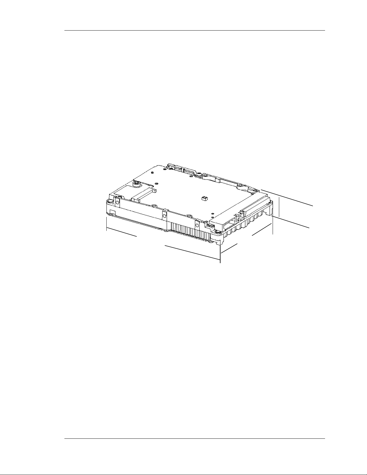
3.2 SPACE REQUIREMENTS
The Quantum Atlas 10K II Ultra 160/m SCSI disk drive is shipped without a
faceplate (or bezel) and comes in the following SCSI interface configurations:
• 68-pin Wide SCSI
• 80-pin SCA-2 SCSI
Figures 3-1 and 3-2 show the mechanical dimensions of disk drives of these two
interface types.
Installation
26.1 mm
(1.02 in.)
147.0 mm
(5.78 in.)
101.6 mm
(4.00 in.)
Figure 3-1 Mechanical Dimensions for the 68-pin Wide SCSI Quantum Atlas 10K II
Ultra 160/m Hard Disk Drive (Low Profile Form Factor)
Quantum Atlas 10K II Ultra 160/m SCSI Hard Disk Drives 3−3
Page 31

Installation
26.1 mm
(1.02 in.)
147.0 mm
(5.78 in.)
101.6 mm
(4.00 in.)
Figure 3-2 Mechanical Dimensions for the 80-pin SCA-2 Quantum Atlas 10K II Ultra
160/m SCSI 9.1/18.2 Disk Drives (Low Profile Form Factor)
Shock Feet
Quantum Atlas 10K II Ultra 160/m SCSI disk drives are outfitted with plastic shock
feet on the bottom edge of the base casting, near the corners, beneath the side
mounting holes (translucent), and near the corners of the top cover next to the
screws (black). The shock feet give an additional level of isolation to prevent the
head and disk damage that occasionally may occur during unpacking, staging, and
installation. The shock feet attenuate the short-pulse shocks that occur when
placing the drive on a hard work surface. If the drive is tested on a hard surface, it
should be supported so that its shock feet are not in contact with the hard surface;
the disk drive should be supported in the middle, between the shock feet.
NOTE
To provide optimal protection, the shock feet are designed to exceed the form
factor when uncompressed.
3−4 Quantum Atlas 10K II Ultra 160/m SCSI Hard Disk Drives
Page 32

3.3 UNPACKING INSTRUCTIONS
The maximum limits for physical shock can be exceeded if the disk drive is
not handled properly. Special care must be taken not to bump or drop the
disk drive.
1. Open the shipping container and remove the packing assembly that contains the
disk drive.
2. Remove the disk drive from the packing assembly.
During shipment and handling, the antistatic electrostatic discharge (ESD)
bag prevents damage to electronic components due to electrostatic
discharge. To avoid accidental damage to the disk drive, do not use a sharp
instrument to open the ESD bag. Save the packing materials for possible
future use.
Installation
CAUTION
CAUTION
3. When you are ready to install the disk drive, remove it from the ESD bag
Figure 3.3 shows the packing assembly for a single Quantum Atlas 10K II Ultra
160/m SCSI hard disk drive. A 12-pack shipping container is available for
multiple drive shipments.
Figure 3-3 Drive Packing Assembly
Quantum Atlas 10K II Ultra 160/m SCSI Hard Disk Drives 3−5
Page 33

Installation
3.4 CONFIGURATION JUMPERS AND CONNECTIONS
This section includes setup and configuration information for Atlas II Ultra 160/m
SCSI disk drives. These disk drives include
• The 16-bit multimode Ultra 160/m SCSI-3 wide version with 68-pin SCSI
connector,
• The 16-bit multimode Ultra 160/m SCSI-3 version with SCA-2 80-pin connector.
Specific individual settings for each drive type are described in sections 3.4.1
through 3.4.2.
WARNING
Before you begin, review the Safety, ESD, and Handling precautions described at the
beginning of this manual to avoid personal injury or damage to equipment.
3.4.1 Jumper Configurations and Connections – Disk Drives with 68-Pin
SCSI Connector
This section describes how to configure the jumpers on Atlas 10K II Ultra 160/m
disks with 68-pin SCSI interface connectors. The following features are jumperselectable:
• TERMPWR
• SCSI ID
• Write Protection
• Spin Up
• Remote LED di splays (BUSY and FAULT. Note that the FAULT LED
illuminates when any diagnostic or functional failure occurs that prevents the
drive from performing logical I/O.)
Note that the disk drive does not support on-board SCSI termination.
Figure 3-4 presents an overview of the jumper and connector locations for the wide,
68-pin connector version of the drive.
3−6 Quantum Atlas 10K II Ultra 160/m SCSI Hard Disk Drives
Page 34

DRIVES WITH 68-PIN SCSI
¡ ¡ ¡ ¡
SCSI
28-Pin Secondary Option Connector
Pin
Pin 1
Pin 28
CONNECTOR
12-Pin Option Connector
§§§§§§§§§§§§§§§§§§§§§§§§§§§§§§§§§§
§§§§§§§§§§§§§§§§§§§§§§§§§§§§§§§§§§
¡ ¡ ¡ ¡ ¡ ¡
¡ ¡ ¡ ¡ ¡ ¡
Pin 12
Back: Connectors
and Jumpers
Power
Installation
12/11 No Connect / +5V
10/9 GND / Reserved
8/7 Busy LED / SCSI ID bit 3
6/5 GND / SCSI ID, bit 2
4/3 GND / SCSI ID, bit 1
2/1 Fault LED / SCSI ID bit 0
28/27 Term Pwr / TermPwr
26/25 Customize / GND
24/23 Enable Narrow / GND
22/21 Stagger Spin / GND
20/19 Write Protect / GND
18/17 Busy LED / +5V
16/15 No Connect / No
Connect
14/13 DiffSense / GND
12/11 Spin Delay / GND
10/9 Key / Fault LED
8/7 SCSI ID, bit 0 / GND
6/5 SCSI ID, bit 1 / GND
4/3 SCSI ID, bit 2 / GND
¡ ¡
Figure 3-4 Jumper and Connector Locations, 68-Pin SCSI Connector Version
Quantum Atlas 10K II Ultra 160/m SCSI Hard Disk Drives 3−7
Page 35

Installation
3.4.1.1 TERMPWR (Disk Drives with 68-Pin SCSI Connector)
To ensure that there is a sufficient level of power along the entire SCSI bus,
Quantum Corporation recommends that all devices on the SCSI bus supply
TERMPWR (if they are capable). SCSI devices are protected by a diode or similar
semiconductor to prevent back flow of the terminator power when more than one
device supplies this power.
Configure the drive to provide TERMPWR by installing a jumper across pin pair 27 /
28 (Figure 3-4) on the Secondary Option Connector located on the front of the drive.
3.4.1.2 SCSI ID (Disk Drives with 68-Pin SCSI Connector)
Each SCSI device on the bus must have a unique SCSI ID number assigned to it.
The drive can be configured for SCSI ID numbers that range from 0 through 15.
Set the SCSI ID for the drive at the 12-pin Option connector or the 28-pin Secondary
Option connector. Jumper locations are shown in Figure 3-4. Use Tables 3-1 and 3-2
to assign SCSI IDs using the Option connector or Secondary Option connector pins
NOTE
Refer to your system or SCSI controller documentation for recommendations
about assigning SCSI ID numbers for your specific system.
3−8 Quantum Atlas 10K II Ultra 160/m SCSI Hard Disk Drives
Page 36

Installation
Table 3-1 SCSI ID Selection on Option Connector (68-Pin SCSI Connector Drives)
Jumper Location – Option Connector
SCSI ID Pin Pair 7 / 8 Pin Pair 5 / 6 Pin Pair 3 / 4 Pin Pair 1 / 2
0 0 0 0 0
1 0 0 0 1
2 0 0 1 0
3 0 0 1 1
4 0 1 0 0
5 0 1 0 1
6 0 1 1 0
7 0 1 1 1
8 1 0 0 0
9 1 0 0 1
10 1 0 1 0
11 1 0 1 1
12 1 1 0 0
13 1 1 0 1
14 1 1 1 0
15 1 1 1 1
0 = Jumper Not Installed
1 = Jumper Installed
Configure the drive for remote (external) SCSI ID selection by removing the SCSI
ID jumpers (if present) from the referenced SCSI ID pins. Then connect the leads
from the external selection switch to the referenced pins. Observe the following
guidelines while doing so:
• ID bit 0, at Pin 1, is the Least Significant Bit.
• SCSI ID bits 0, 1, 2, and 3 (pins 1, 3, 5, and 7, respectively) are active LOW
signals. That is, the bit is a 1 if the corresponding remote switch is closed to
ground.
• Use pins 2, 4, 6 and 8 as the associated ground returns for ID bits 0, 1, 2, and 3,
respectively. The ground returns can be used individually, or the ground returns
of all four ID bits can be combined at pin 10.
Quantum Atlas 10K II Ultra 160/m SCSI Hard Disk Drives 3−9
Page 37

Installation
Table 3-2 Jumper Settings for SCSI ID, 28-Pin Secondary Option Connector
Jumper Location – Secondary Option Connector
SCSI ID Pin Pair 7 / 8 Pin Pair 5 / 6 Pin Pair 3 / 4 Pin Pair 1 / 2
0 0 0 0 0
1 1 0 0 0
2 0 1 0 0
3 1 1 0 0
4 0 0 1 0
5 1 0 1 0
6 0 1 1 0
7 1 1 1 0
8 0 0 0 1
9 1 0 0 1
10 0 1 0 1
11 1 1 0 1
12 0 0 1 1
13 1 0 1 1
14 0 1 1 1
15 1 1 1 1
0 = Jumper Not Installed
1 = Jumper Installed
3.4.1.3 Write Protection (Disk Drives with 68-Pin SCSI Connector)
To configure Write Protection for the drive, install a jumper across pin pair 19 / 20
on the Secondary Option Connector (Figure 3-4). To disable Write Protection on the
drive, remove the jumper.
3.4.1.4 Spin Up (Disk Drives with 68-Pin SCSI Connector)
Atlas 10K II Ultra 160/m SCSI drives have three Spin Up modes:
• Option 1: Spin up immediately when power is applied: Verify that no jumper
is installed across pin pair 11 / 12 (GND / Spin Delay) of the
Secondary Option connector (Figure 3-4).
• Option 2: Spin up after a predetermined delay following power on : Install
jumpers across pin pair 11 / 12 (GND / Spin Delay) and across pin
pair 21 / 22 (GND / Stagger Spin) on the Secondary Option
connector (Figure 3-4). Set the delay parameters with the MODE
SELECT command, Quantum-Unique Page (39h). The delay is equal
to a user-specified multiplier, multiplied by the numerical SCSI ID of
the drive. This will give a staggered spin-up in multiple-drive
installations.
• Option 3: Spin up on START STOP UNIT command: Install a jumper across
pin pair 11 / 12 (GND / Spin Delay) and remove any jumper from
pin pair 21 / 22 (GND / Stagger Spin), if a jumper is installed there,
on the Secondary Option connector (Figure 3-4).
3−10 Quantum Atlas 10K II Ultra 160/m SCSI Hard Disk Drives
Page 38

Installation
3.4.1.5 Enable Narrow Mode (Force 8) (Disk Drives with 68-Pin SCSI
Connector)
Wide Data Transfer (WDTR) negotiations can be limited to 8-bit responses either by
setting the Force 8 bit of the Quantum-Unique Page (39h) of the MODE SELECT
command (15h) to 1, or by installing a jumper on pin pair 23 / 24 of the Secondary
Option Connector (Figure 3-4).
3.4.1.6 Remote Busy and Fault Displays (Disk Drives with 68-Pin SCSI
Connector)
Busy and Fault status of the drive can be monitored remotely by connecting a remote
(external) Busy and/or remote Fault display LEDs to the appropriate pins on the 12pin Option Connector or the 28-pin Secondary Option Connector.
Remote Busy LED
On the Option Connector, connect the cathode side of the remote Busy LED to pin
8, Busy LED (Figure 3-4). Connect the anode side of the LED to pin 11, +5V.
On the Secondary Option Connector, connect the cathode side of the remote Busy
LED to pin 18, Busy LED (Figure 3-4). Connect the anode side of the LED to pin
17, +5V.
Remote Fault
On the Option Connector, connect the cathode side of the remote Fault LED to pin
2, Fault LED (Figure 3-4). Connect the anode side of the LED to pin 11, +5V.
On the Secondary Option Connector, connect the cathode side of the remote Fault
LED to pin 9, Fault LED (Figure 3-4). Connect the anode side of the LED to pin 17,
+5V.
Quantum Atlas 10K II Ultra 160/m SCSI Hard Disk Drives 3−11
Page 39

Installation
3.4.2 Jumper Configurations and Connections for SCA-2 Connector
Versions
This section describes jumper settings and connections for Atlas 10K II Ultra 160/m
SCSI drives with 80-pin SCA-2 (Single Connector Attachment) connector for the
following features:
• SCSI ID
• Spin Up
• Activity LED displays
Use Figure 3-5 to locate the appropriate pins for configuring the drive. Note that
Figure 3-5 does not call out each of the 80 pins on the connector, but rather
illustrates the layout of the pins.
NOTE
The SCA-2 Connector version of the disk drives do not provide TERMPWR,
Active Termination, or Write Protection.
3.4.2.1 Termination for SCA-2 Connector Versions
These versions of Atlas 10K II Ultra 160/m SCSI disk drives cannot be configured to
provide bus termination. Therefore, be sure to properly terminate the SCSI bus on
which this drive is installed.
NOTE
Refer to your system or SCSI controller documentation regarding any
additional recommendations regarding drive placement on the SCSI bus and
SCSI bus termination.
3.4.2.2 SCSI ID for SCA-2 Connector Versions
Each SCSI device on the bus must have a unique SCSI ID number assigned to it.
The drive can be configured for SCSI ID numbers that range from 0 through 15.
Configure the SCSI ID by providing the proper open or ground signal inputs to the
referenced pins of the drive’s 80-pin new version SCA-2 connector (Figure 3-5). Refer
to Table 3-3 for SCSI ID pin assignments.
NOTE
Refer to your system or SCSI controller documentation for specific
recommendations about assigning SCSI ID numbers for your specific system.
3−12 Quantum Atlas 10K II Ultra 160/m SCSI Hard Disk Drives
Page 40

Installation
Pin 40 Pin 39
Pin 80 Pin 79
HDA
Pin 2 Pin 1
Pin 42 Pin 41
Figure 3–5 Pin Locations on SCA-2 Connector
Table 3–3 SCSI ID Pin Assignments (SCA-2 Connector Versions of the Disk Drive)
Location on SCA Connector
SCSI ID ID3 - Pin 80 ID2 - Pin 40 ID1 - Pin 79 ID0 - Pin 39
0 0 0 0 0
1 0 0 0 1
2 0 0 1 0
3 0 0 1 1
4 0 1 0 0
5 0 1 0 1
6 0 1 1 0
7 0 1 1 1
8 1 0 0 0
9 1 0 0 1
10 1 0 1 0
11 1 0 1 1
12 1 1 0 0
13 1 1 0 1
14 1 1 1 0
15 1 1 1 1
0 = Open Circuit, +2.4 V to Vcc +0.5 V
3.4.2.3 Spin Up for SCA-2 Connector Versions
Atlas 10K II drives with SCA-2 SCSI connectors have three Spin Up modes:
• Option 1 Spin up occurs immediately when power is applied.
• Option 2 Drive spin up occurs after a predetermined delay following power on.
Set the delay parameters with the MODE SELECT Command,
Quantum-Unique Page (39h).The delay is equal to a user-specified
multiplier multiplied by the numerical SCSI ID of the drive. This
will give a staggered spin-up in multiple-drive installations.
• Option 3 Drive spin up is controlled by the START STOP UNIT command.
Configure the desired spin up option (Table 3-4) by setting the state of the
DELAY_SPIN (Pin 38) and STAGGER_SPIN (Pin 78) inputs on the 80-pin SCA-2
connector (Figure 3-5). The states of these signals are set by using either hard-wired
connections at the backplane or backplane logic.
Quantum Atlas 10K II Ultra 160/m SCSI Hard Disk Drives 3−13
Page 41

Installation
Table 3–4 Spin Up on Power On Options
STAGGER_SPIN
Option
(Pin 78)
DELAY_SPIN
(Pin 38)
Option 1 – Spin Up When
Power is
Applied
Option 2 – Spin Up After
Delay
Option 3 – Spin Up on
START
Command
Reserved Ground Ground
Open Open
Ground Open
Open Ground
3.4.2.4 Activity LED for SCA-2 Connector Versions
The drive provides the output BUSY_OUT signal to power a user-supplied activity
LED.
The output indicates the drive is performing a SCSI operation. To use this output,
connect a user-supplied LED cathode to the BUSY_OUT connection, pin 77 on the
SCA Connector (Figure 3-5). The LED anode must be attached to the proper +5
VDC supply through an appropriate current-limiting resistor.
3−14 Quantum Atlas 10K II Ultra 160/m SCSI Hard Disk Drives
Page 42

3.4.2.5 Force Single-Ended Operation for SCA-2 Connector Versions
Pin 2
Pin 1
Pin 3
Pin 4
A jumper is provided to force the disk drive to operate as a single-ended device. See
the explanation of the LVD SCSI interface in Chapter 7 for details.
To force the disk drive to operate as a single-ended device, install the low profile
jumper across pin pair 1 / 3 (Figure 3-6). For LVD operation and monitoring of
DIFFSENS signal, place the jumper across pin pair 2 / 4.
Figure 3-6 Force Single-Ended Operation Jumper Locations
Force single-ended jumper shown
installed across Pin Pair 1 / 3. This forces
the disk to operate as a single-ended
device and disables its ability to monitor
DIFFSENS.
Installation
Remove the jumper or park it across Pin
Pair 2 / 4 to enable the disk drive’s
DIFFSENS monitoring feature, required for
LVD SCSI.
Quantum Atlas 10K II Ultra 160/m SCSI Hard Disk Drives 3−15
Page 43

Installation
Pin 28
1
3.5 CONNECTOR PINOUTS AND WIRING DIAGRAMS
Atlas 10K II Ultra 160/m SCSI disk drive interfaces include a 16-bit wide SCSI
version and a SCA-2 connector version. Connector pinout information for the drive
and signal connection diagrams are found in this section.
3.5.1 Atlas 10K II Ultra 160/m SCSI Disk Drive with 68-Pin SCSI Connector
Figure 3-7 shows the locations of the Power, SCSI, Option, and Secondary Option
Connectors on the68-pin SCSI connector version of the drive. Figure 3-7 also
provides the locations and names of the signals connected to the pins at the Option
and Secondary Option Connectors on the drive. Table 3-5 provides signal names/pin
locations for the 68-pin wide SCSI connector.
35
68
1 121
Power Connector Option Connector
Option Connector Signals
Pin - Signal Pin - Signal
1 - SCSI ID, bit 0 2 - Fault LED
3 - SCSI ID, bit 1 4 - GND
5 - SCSI ID, bit 2 6 - GND
7 - SCSI ID, bit 3 8 - Busy LED
9 - Reserved 10 - GND
11 - +5 V 12 - No Connect
HDA
SCSI Connector
Secondary Option Connector
Secondary Option Connector Signals
Pin - Signal Pin - Signal
1 - GND 2 - SCSI ID, bit 3
3 - GND 4 - SCSI ID, bit 2
5 - GND 6 - SCSI ID, bit 1
7 - GND 8 - SCSI ID, bit 0
9 - Fault LED 10 - key
11 - GND 12 - Spin Delay
13 - GND 14 - DiffSense
15 - No Connect 16 - No Connect
17 - +5V 18 - Busy LED
19 - GND 20 - Write Protect
21 - GND 22 - Stagger Spin
23 - GND 24 - Enable Narrow
25 - GND 26 - Customize
27 - TermPwr 28 - TermPwr
34
Pin 1
Figure 3-7 Connectors on 68-Pin SCSI Connector Versions of Atlas 10K II Ultra 160/m Hard
Disk Drives
3−16 Quantum Atlas 10K II Ultra 160/m SCSI Hard Disk Drives
Page 44

Installation
Table 3-5 68-Pin Wide (LVD) SCSI Connector Pin Assignments
Signal Name Pin Number Pin Number Signal Name
+DB(12) 1 35 -DB(12)
+DB(13) 2 36 -DB(13)
+DB(14) 3 37 -DB(14)
+DB(15) 4 38 -DB(15)
+DB(P1) 5 39 -DB(P1)
+DB(0) 6 40 -DB(0)
+DB(1) 7 41 -DB(1)
+DB(2) 8 42 -DB(2)
+DB(3) 9 43 -DB(3)
+DB(4) 10 44 -DB(4)
+DB(5) 11 45 -DB(5)
+DB(6) 12 46 -DB(6)
+DB(7) 13 47 -DB(7)
+DB(P) 14 48 -DB(P)
GROUND 15 49 GROUND
DIFFSENS 16 50 GROUND
TERMPWR 17 51 TERMPWR
TERMPWR 18 52 TERMPWR
RESERVED 19 53 RESERVED
GROUND 20 54 GROUND
+ATN 21 55 -ATN
GROUND 22 56 GROUND
+BSY 23 57 -BSY
+ACK 24 58 -ACK
+RST 25 59 -RST
+MSG 26 60 -MSG
+SEL 27 61 -SEL
+C/D 28 62 -C/D
+REQ 29 63 -REQ
+I/O 30 64 -I/O
+DB(8) 31 65 -DB(8)
+DB(9) 32 66 -DB(9)
+DB(10) 33 67 -DB(10)
+DB(11) 34 68 -DB(11)
NOTE
A negative sign (-) before a signal indicates an active-low signal.
Quantum Atlas 10K II Ultra 160/m SCSI Hard Disk Drives 3−17
Page 45

Installation
3.5.2 Atlas 10K II Ultra 160/m SCSI Disk Drive With 80-Pin, SCA-2 SCSI
Connector
Figure 3-8 shows the location of the SCSI Connector on this version of the drive.
Table 3-6 provides signal names/pin locations for the 80-pin SCA-2 SCSI connector.
Pin 40 Pin
SCSI SCA-2 Connector
Pin 80 Pin 79
Pin 2 Pin 1
Pin 42 Pin
HDA
Figure 3-8 SCA-2 Connector on Quantum Atlas 10K II Ultra 160/m SCSI Hard Disk Drive
3−18 Quantum Atlas 10K II Ultra 160/m SCSI Hard Disk Drives
Page 46

Installation
Table 3-6 80-Pin SCA-2 SCSI Connector Pin Assignments
Signal Name Pin Number Pin Number Signal Name
+12 V 1 41 12V GROUND
+12 V 2 42 12V GROUND
+12 V 3 43 12V GROUND
+12 V 4 44 MATED 1
NO CONNECT 5 45 NO CONNECT
NO CONNECT 6 46 SCSI_DIFFSENS
-DATA_M(11) 7 47 DATA_P(11)
-DATA_M (10) 8 48 DATA_P(10)
-DATA_M B(9) 9 49 DATA_P(9)
-DATA_M(8) 10 50 DATA_P(8)
-SCSI_I/O 11 51 SCSI_I/O_P
-SCSI_REQ 12 52 SCSI_REQ_P
-SCSI_C/D 13 53 SCSI_C/D_P
-SCSI_SEL 14 54 SCSI_SEL_P
-SCSI_MSG 15 55 SCSI_MSG_P
-SCSI_RST 16 56 SCSI_RST_P
-SCSI_ACK 17 57 SCSI_ACK_P
-SCSI_BSY 18 58 SCSI_BSY_P
-SCSI_ATN 19 59 SCSI_ATN_P
-SCSI_PARITY_M(0) 20 60 SCSI_PARITY_P(0)
-DATA_M(7) 21 61 DATA_P(7)
-DATA_M(6) 22 62 DATA_P(6)
-DATA_M(5) 23 63 DATA_P(5)
-DATA_M(4) 24 64 DATA_P(4)
-DATA_M(3) 25 65 DATA_P(3)
-DATA_M(2) 26 66 DATA_P(2)
-DATA_M(1) 27 67 DATA_P(1)
-DATA_M(0) 28 68 DATA_P(0)
-SCSI_PARITY_M(1) 29 69 SCSI_PARITY_P(1)
-DATA_M(15) 30 70 DATA_P(15)
-DATA_M(14) 31 71 DATA_P(14)
-DATA_M(13) 32 72 DATA_P(13)
-DATA_M(12) 33 73 DATA_P(12)
+5V 34 74 GROUND (MATED 2)
+5V 35 75 5V GROUND
+5V 36 76 5V GROUND
RESERVED 37 77 ACTIVE LED OUT
-DELAY_SPIN 38 78 -STAGGER_SPIN
-SCSI ID (0) 39 79 -SCSI ID (1)
-SCSI ID (2) 40 80 -SCSI ID (3)
NOTE
A negative sign (-) before a signal indicates an active-low signal.
Quantum Atlas 10K II Ultra 160/m SCSI Hard Disk Drives 3−19
Page 47

Installation
3.6 DRIVE MOUNTING AND INSTALLATION
This section provides information for installing the disk drive and for connecting the
SCSI and power cables as applicable.
WARNING
Before you begin, review the Safety, ESD, and Handling precautions described in
the beginning of this manual to avoid personal injury or damage to the drive.
3.6.1 Orientation
The drive can be mounted in any position. Figures 3–9 and 3-10 show the drive base
assembly, with mounting locations and dimensions indicated.
Figure 3-9 Mounting Dimensions for the 68-pin Quantum Atlas 10K II Ultra 160/m
SCSI Hard Disk Drive
3−20 Quantum Atlas 10K II Ultra 160/m SCSI Hard Disk Drives
Page 48

Installation
Figure 3-10 Mounting Dimensions for the 80-pin SCA-2 Quantum Atlas 10K II Ultra
160/m SCSI Hard Disk Drive
3.6.2 Mounting Screw Clearance
The printed circuit board assembly (PCBA) is very close to the mounting holes.
Do not exceed the specified length for the mounting screws. The specified
screw length allows full use of the mounting hole threads while avoiding
damaging or placing unwanted stress on the PCBA.
Figure 3-11 specifies the minimum clearance between the PCBA and the screws
in the mounting holes. The maximum torque applied to the screws must not
exceed 14 inch-pounds (1.57 N-m). A maximum screw length of 0.22 inches
(5.59 mm) may be used in the side mounting locations when a bracket of 0.04
inches (1.016 mm) minimum thickness is used.
CAUTION
Quantum Atlas 10K II Ultra 160/m SCSI Hard Disk Drives 3−21
Page 49

Installation
The PCBA is very close to the mounting holes. Figure 3-11 specifies the clearance
between the screws in the mounting holes and the PCBA. Do not use mounting
screws longer than the maximum lengths specified in Figure 3-11. The specified
screw length allows full use of the mounting hold threads while avoiding damage or
stress on the PCBA. Clearance from the disk drive to any other surface (except
mounting surfaces) must be a minimum of 0.05 inches (1.25 mm).
Leave this mounting hole unused when
installing the drive with less than 4 bottom
mounting screws.
Figure 3-11 Mounting Screw Clearance for the Quantum Atlas 10K II Ultra 160/m
SCSI Hard Disk Drive
3−22 Quantum Atlas 10K II Ultra 160/m SCSI Hard Disk Drives
Page 50

3.6.3 Shock Clip
The shock clip provides an extra level of isolation from the occurrence of a short
duration, non-operational shock, particularly when the disk drive is mounted on a
rigid platform.
To prevent the possibility of a cross-threaded screw, it is recommended that
the screws associated with the fixed side mounting locations be started before
the screw associated with the shock clip. Install all of the applicable screws
before the final torquing process.
Shock performance is optimal when either four bottom mount locations or
four outer side screw locations are used.
3.6.4 Mounting
For the best results during performance benchmark testing, it is recommended that
the disk drive be mounted firmly within a system or a fixture, rather than sitting
unconstrained on a tabletop or work surface. If it is necessary to perform testing on
an unconstrained disk drive, place the disk drive on a flat, smooth, semi-cushioned
surface (similar to a mousepad). This avoids any performance degradations due to
possibly higher incidence of recovered errors. The disk drive should not be operated
on a hard surface.
Installation
CAUTION
3.6.5 Ventilation
The Quantum Atlas 10K II Ultra 160/m SCSI hard disk drive operates without a
cooling fan, provided the ambient air temperature does not exceed 131ºF (55ºC).
Figures 3-12 and 3-13 show possible configurations for airflow required for adequate
cooling. Clearance from the drive to any other surface above and below the disk drive
must be a minimum of 1/16-inch (1.25 mm).
Figure 3–12 Lengthwise Airflow Cooling
Quantum Atlas 10K II Ultra 160/m SCSI Hard Disk Drives 3−23
Page 51

Installation
Figure 3–13 Widthwise Airflow Cooling
3.6.6 Installation in a 3.5-inch Bay
Screw-length must not exceed 0.25-inch (6.25 millimeters) or the drive may
be damaged.
The drive base contains threaded holes on its sides and bottom to mount the drive
(see Figure 3-9 or Figure 3-10). The holes accept #6-32 screws.
Mounting brackets may used when installing the drive in a 5.25-inch form
factor bay. Brackets supplied by Quantum Corporation to mount the drive are
recommended, otherwise, the drive’s isolation characteristics may be
affected. A Bracket kit (part no. 70-30695-01) is available from the Quantum
Corp.
To mount the drive:
1. Position the completed drive in the drive bay and choose the drive base
mounting holes that match the bay mounting locations.
CAUTION
NOTE
2. Insert and secure the screws at the selected locations.
3−24 Quantum Atlas 10K II Ultra 160/m SCSI Hard Disk Drives
Page 52

3.6.7 Installation in a 5.25-inch Bay
Screws used to mount the drive must not exceed 0.25-inch
(6.25 millimeters) in length, or the drive may be damaged.
Figure 3-14 shows the brackets representative of those used to mount the drive in a
5.25-inch bay. A bracket kit including four screws is available from Quantum
Corporation. The part number of the kit is 70-30695-01.
CAUTION
SIDE
BRACKET
Installation
SIDE
BRACKET
Figure 3-14 Brackets for 5.25-inch Bay
Attach the brackets to the drive using four #6-32 screws (see Figure 3-11).
Mount the drive in the bay by performing the following steps:
1. Position the completed unit (drive and brackets) in the bay.
2. Secure the unit with screws at the selected mounting hole locations.
3.6.8 Backplane Installation (SCA Drive)
CAUTION
Screws used to mount the drive must not exceed 0.25-inch
(6.25 millimeters) in length, or the drive may be damaged.
Because of the variety of mounting possibilities, these instructions are general in
nature. They should be used only as a guide for mounting the drive in your
particular system.
Mount the drive as follows:
1. Position the drive in the bay.
2. Align the RAID connector on the drive to the backplane connector in the
system.
Quantum Atlas 10K II Ultra 160/m SCSI Hard Disk Drives 3−25
Page 53

Installation
3.6.9 Drive Connections
3.6.9.1 SCSI Bus Connection
3. Insert the RAID connector of the drive into the system backplane
connector, being careful not to damage any connector pins.
4. Secure the drive in the RAID system with #6-32x1/4 UNC screws. Use
the side mount or bottom mount holes, depending upon enclosure
mounting hole requirements.
NOTE
To ensure proper operation of the drive, run any required software after the
installation is completed.
The drive connects to both the SCSI and power buses.
Align the system SCSI bus cable connector to J1 on the drive. Connect the cable
to J1 carefully to avoid bending or damaging the connector pins. Drives with
SCA connector may plug directly into a backplane connector
The connectors used on the drive vary with the drive type:
• Wide Ultra3 SCSI-3 drives with 68-pin SCSI Connector – Combination
Connector containing 68-pin SCSI connector, 4-pin Power Connector,
and 12-pin Option Connector (Figure 3-7).
• Wide Ultra3 SCSI-3 drives with 80-pin SCA-2 connector providing SCSI,
Power, and configuration/option inputs (Figure 3-8).
3.6.9.2 Power Connection
Align the system power cable connector to the drive power connector J2 (Figure
3-15). Connect the system power cable to J2 carefully to avoid bending or
damaging the connector pins. Note that drives with SCA-2 connector do not
have this separate J2 Power Connector.
Figure 3-15 Drive Power Connector J2
3−26 Quantum Atlas 10K II Ultra 160/m SCSI Hard Disk Drives
Page 54

3.6.9.3 Cables
Furnish the appropriate cables and connectors to match the drive connectors listed
in Table 3–7.
Connector/Jumper Quantum (or Vendor) Part Number
68-pin SCSI connector Quantum 23-409326-01
(includes a 68-pin SCSI connector, Molex 87360-0009
a 4-pin power connector, and a 2 mmpitch, 12-pin (2x6) option connector)
23-pin secondary option connector Quantum TBD
[2 mm-pitch 2X14 keyed connector JAE TBD
Installation
Table 3–7 Connectors and Jumpers
16-bit Wide SCSI (68-Pin)
Single Connector Attachment SCSI (80-Pin, SCA-2)
RAID connector (Champ 0.050 inch Quantum 23-416824-80
Series I 80-position plug) AMP 1123283-9
Shunt Jumper (All drives)
2 mm-pitch shunt for configuration Quantum 23-400479-01
of drive characteristics Augat CN-AX027C5A02
Berg 86730-001
Quantum Atlas 10K II Ultra 160/m SCSI Hard Disk Drives 3−27
Page 55

Installation
3−28 Quantum Atlas 10K II Ultra 160/m SCSI Hard Disk Drives
Page 56

This chapter provides a detailed description of the physical, electrical, and
environmental characteristics of the Quantum Atlas 10K II 160/m SCSI hard disk
drives.
4.1 SPECIFICATION SUMMARY
Table 4-1 Specifications
Chapter 4
SPECIFICATIONS
QUANTUM
DESCRIPTION
Formatted Capacity 9.10 GB 18.4 GB 36.7 GB 73.4 GB
Nominal Rotational Speed (rpm) 10,000 10,000 10,000 10,000
Number of Disks 2 3 5 10
Number of R/W Heads 3 5 10 20
Maximum Areal Density
(Gb/square inch)
Data Organization:
User Data Tracks per Surface 17337 17337 17337 17337
Data Bands per Surface 24 24 24 24
User Data Track Pitch
(at 14,200 tpi)
Data Blocks/Track 301 – 528
Data Cylinders 17337 17337 17337 17337
Servo Sectors:
Servo Spokes/Track
Servo Sample Interval
Bytes Per Sector 512 to 524 512 to 524 512 to 524 512 to 524
Recording:
Recording Technology ID-less Split
Linear Density (Kfci) ID = 341.6
Encoding Method 50/52 RLL
ATLAS 10K II
9.1 GB
7.7 7.7 7.7 7.7
22500 22500 22500 22500
(ID – OD)
132 (all tracks)
45.45 µsec
Sector
OD = 306.1
PRML
QUANTUM
ATLAS 10K II
18.4 GB
301 – 528
(ID – OD)
132 (all tracks)
45.45 µsec
ID-less Split
Sector
ID = 341.6
OD = 306.1
50/52 RLL
PRML
QUANTUM
ATLAS 10K II
36.7 GB
301 – 528
(ID – OD)
132 (all tracks)
45.45 µsec
ID-less Split
Sector
ID = 341.6
OD = 306.1
50/52 RLL
PRML
QUANTUM
ATLAS 10K II
73.4 GB
301 – 528
(ID – OD)
132 (all tracks)
45.45 µsec
ID-less Split
Sector
ID = 341.6
OD = 306.1
50/52 RLL
PRML
Quantum Atlas 10K II Ultra 160/m SCSI Hard Disk Drives 4-1
Page 57

Specifications
Table 4-1 Specifications (continued)
DESCRIPTION
QUANTUM
ATLAS 10K II
9.1 GB
QUANTUM
ATLAS 10K II
18.2 GB
QUANTUM
ATLAS 10K II
36.4 GB
QUANTUM
ATLAS 10K II
72.8 GB
Buffer Size 8 MB 8 MB 8 MB 8 MB
RELIABILITY:
Annualized Failure Rate (AFR)1No greater than
1.5%
Seek Error Rate 10 in 10
Recoverable Error Rate 10 in 10
Unrecoverable Error Rate 10 in 10
Grown Defects from
Environmental Change
(Maximum)
2
Minimum Contact Start/Stop
6
12
14
18 36 72 144
40,000 40,000 40,000 40,000
No greater than
1.5%
10 in 10
10 in 10
10 in 10
6
12
14
No greater than
1.5%
10 in 10
10 in 10
10 in 10
6
12
14
No greater than
1.5%
10 in 10
10 in 10
10 in 10
Cycles @ 25°C (77°F)
Auto Head-Park Method AirLock® – with
magnetic bias
AirLock® – with
magnetic bias
AirLock® – with
magnetic bias
AirLock® – with
magnetic bias
NOTES
1
Projected AFR is from a predicted theoretical AFR for the Atlas 10K IIfamily of
products that is based on design (i.e., Bellcore) and historical data and does not
include process variance, returns with no trouble found, or handling and excessive
shock failures. Historically, the field AFR, which returns all returns regardless of cause,
has been 50 – 60% of the projected AFR. The development of an operational AFR
methodology and derating curve, in line with the IDEMA AFR standardization effort,
is underway. For more information, see the HDD Reliability White Paper on Quantum
Corporation’s World Wide Web site at www.quantum.com.
2
With AWRE and ARRE set to 1, the drive will add detected bad blocks to the Grown
Defect List and reallocate the data. A small number of grown defects can occur,
typically during the first 48 hours of I/O activity, as a result of significant
environmental change. This change includes specification extremes (altitude,
voltage, temperature, shock, vibration, etc.) not encountered during the
manufacturing test process. Environmental extremes and shocks encountered during
shipping and handling may also lead to grown defects.
6
12
14
4-2 Quantum Atlas 10K II Ultra 160/m SCSI Hard Disk Drives
Page 58

4.2 FORMATTED CAPACITY
The Quantum Atlas 10K II Ultra 160/m SCSI hard disk drives receive a low-level
format at the manufacturing facility. This formatting creates the actual tracks and
sectors on the disk drive. Table 4-2 shows the storage capacities of the three different
disk drives that result from this process. Formatting done at the user level, for
operation with DOS, UNIX, or other operating systems, will result in less capacity
than the physical capacity shown.
Specifications
Table 4-2 Formatted Capacity
QUANTUM
DESCRIPTION
Formatted Capacity 9.2 GB 18.4 GB 36.7 GB 73.4 GB
User Data Blocks/Surface 17,938,986 35,860,910 71,721,820 143,443,640
ATLAS 10K II
9.2 GB
QUANTUM
ATLAS 10K II
18.4 GB
QUANTUM
ATLAS 10K II
36.7 GB
QUANTUM
ATLAS 10K II
73.4 GB
Quantum Atlas 10K II Ultra 160/m SCSI Hard Disk Drives 4-3
Page 59

Specifications
4.3 DATA TRANSFER RATES
Table 4-3 shows the data transfer rates for the Quantum Atlas 10K II Ultra 160/m
SCSI disk drives. Specifications are for both the 68-pin Wide and SCA-2 connector
versions of the disk drive.
Table 4-3 Transfer Rates
DESCRIPTION
Interface Transfer Rate
(MB/second)
Media Transfer Rate
Channel Rate
User Data Rate
Data Streaming Rate
(min/max, MB per sec.)
Weighed Ave. Streaming
Rate (MB per sec.)
QUANTUM
ATLAS 10K II
9.1 GB
160 160 160 160
38.2 – 26.09
MB/second
42.0 – 31.0
MB/second
29/40 24/40 24/40 24/40
22.77 22.77 22.77 22.77
QUANTUM
ATLAS 10K II
18.2 GB
38.2 – 26.09
MB/second
42.0 – 26.0
MB/second
QUANTUM
ATLAS 10K II
36.7 GB
38.2 – 26.09
MB/second
42.0 – 19.5
MB/second
QUANTUM
ATLAS 10K II
73.4 GB
38.2 – 26.09
MB/second
42.0 – 19.5
MB/second
4-4 Quantum Atlas 10K II Ultra 160/m SCSI Hard Disk Drives
Page 60

4.4 TIMING SPECIFICATIONS
Table 4-4 illustrates the timing specifications of the Quantum Atlas 10K II Ultra
160/m SCSI disk drives.
Specifications
Table 4-4 Timing Specifications
DESCRIPTION
QUANTUM
ATLAS 10K II
9.2 GB
QUANTUM
ATLAS 10K II
18.4 GB
QUANTUM
ATLAS 10K II
36.7 GB
QUANTUM
ATLAS 10K II
73.4 GB
Seek Times (All Nominal):
Single Track Seek
Average Seek (READ)
Average Seek (WRITE)
Average Access to Data
Average Head Switch Time
Full Stroke Seek (Max. Seek)
Average Rotational Latency
Command Overhead, Seek
.6 ms
4.7 ms
4.7 ms
7.9 ms
0.6 ms
12 ms
3 ms
200 us
.6 ms
4.7 ms
4.7 ms
7.9 ms
0.6 ms
12 ms
3 ms
200 us
.6 ms
4.7 ms
4.7 ms
7.9 ms
0.6 ms
12 ms
3 ms
200 us
.6 ms
5.2 ms
5.2 ms
8.4 ms
0.6 ms
13 ms
3 ms
200 us
Start/Stop Times:
Time to Data Available1 (from SCSI
START command)
Time to Data Available2 (from
power up)
Nominal: 15
seconds
Nominal: 25
seconds
Nominal: 15
seconds.
Nominal: 25
seconds
Nominal: 15
seconds
Nominal: 25
seconds
Nominal: 17
seconds
Nominal: 27
seconds
Spin Down Time 12 seconds 12 seconds 12 seconds 14 seconds
NOTES FOR TABLE 4-4
1
Time to Data Available from SCSI start command assumes that the SPIN DELAY
jumper is installed and power has been supplied to the disk drive with the PCBA
ready. Measurement is from the issue of a SCSI START command until a good test
unit status is received from the disk drive.
2
Time to Data Available from power up assumes that no SPIN DELAY jumper is
installed. Measurement is from the time power is applied until a good test unit status
is received from the disk drive.
Quantum Atlas 10K II Ultra 160/m SCSI Hard Disk Drives 4-5
Page 61

Specifications
4.5 POWER
The Quantum Atlas 10K II Ultra 160/m SCSI hard disk drive operates from two
supply voltages:
+12V ±5%
+5V ±5%
The allowable ripple and noise (60Hz – 100MHz) is 150 mV peak-to-peak, for the
+12V supply and 75 mV peak-to-peak, for the +5V supply.
4.5.1 Power Sequencing
Power may be applied in any order or manner, or open either the power or power
return line with no loss of data or damage to the disk drive. However, data may be
lost in the sector being written at the time of a power loss. The disk drive can
withstand transient voltages of +10% to –100% from nominal while powering up or
down.
4.5.2 Power Reset Limits
When powering up, the disk drive remains reset until both VHT reset limits in Table
4-5 are exceeded. When powering down, the drive becomes reset when either supply
voltage drops below the VLT threshold.
Table 4-5 Power Reset Limits*
DC VOLTAGE THRESHOLD
+5V VLT = 4.25V minimum
V
= 4.365V maximum
HT
+12V VLT = 10.16V minimum
V
= 10.48V maximum
HT
* Includes a 75 mV peak-to-peak ripple on +5V or 150 mV
peak-to-peak ripple on +12V to maximize or minimize values.
4-6 Quantum Atlas 10K II Ultra 160/m SCSI Hard Disk Drives
Page 62

4.5.3 Power Requirements
This section lists the various power specifications for the Quantum Atlas 10K II
Ultra 160/m SCSI hard disk drives.
4.5.3.1 Power Consumption
Startup (Peak) 38.8 W* 38.8 W* 38.8 W* 47.6 W*
40% Seek (ECMA) 15.0 W 15.0 W 16.7 W 20.7 W
Idle 8.6 W 8.6 W 9.9 W 14.7 W
* Quantum Corporation’s startup peak current measurements are based on a
2.5 ms sampling rate. The industry typical sampling rate is 20ms and,
therefore, the Quantum stated startup peak power data appear to be higher
than the industry typical numbers.
Specifications
Maximum Watts
9.2 GB 18.4 GB 36.7 GB 73.4 GB
ECMA Seek Rate is defined in ECMA standard 74. It corresponds to 52
random seeks per second.
4.5.3.2 DC Voltage Tolerances
Nominal Voltage Voltage Tolerance Absolute Limits
5 Vdc Supply ± 5% 4.75 - 5.25 Vdc
12 Vdc Supply ± 5% (±6% transient during spin-up) 11.4 - 12.6 Vdc
Polarity must not be reversed at any time. Reversing polarity at any time on
either power line may damage components. Voltage is measured at the drive
power connector.
NOTE
CAUTION
Quantum Atlas 10K II Ultra 160/m SCSI Hard Disk Drives 4-7
Page 63

Specifications
4.5.3.3 Current Requirements
Typical currents are at nominal supply voltages.
Spin-Up Mode
Typical / Maximum Current
9.2 GB 18.4 GB 36.7 GB 73.4 GB
5 Vdc Supply, Avg. 740.2 / 810* mA 686.0 / 820* mA 731.8 / 820* mA 719.5 / 820* mA
12 Vdc Supply, Avg. 2524.5 / 2850 mA,
peak
* This value achieved during calibration.
Idle Mode
5 Vdc Supply, Avg. 570 mA 580 mA 580 mA 570 mA
12 Vdc Supply, Avg. 490 mA 610 mA 610 mA 1030 mA
ECMA Seek Mode
(ECMA Seeking) 9.2 GB 18.4 GB 36.7 GB 73.4 GB
5 Vdc Supply, Avg. 600 mA 610 mA 610 mA 590 mA
12 Vdc Supply, Avg. 960 mA 1080 mA 1080 mA 1450 mA
ECMA Seek Rate is defined in ECMA standard 74. It corresponds to 52
random seeks per second.
2475.1 / 2860 mA,
peak
9.2 GB 18.4 GB 36.7 GB 73.4 GB
NOTE
2507.4 / 2860 mA,
peak
Maximum
Maximum
3221.5 / 3740 mA,
peak
4-8 Quantum Atlas 10K II Ultra 160/m SCSI Hard Disk Drives
Page 64

4.5.3.4 Current Transients
Spin-Up Mode
Max. Positive Rate of Change +2.0 A in 200 µs
Max. Negative Rate of Change -2.0 A in 50 µs
12 Vdc Supply Regulations ± 5%
Active Mode (ECMA Seeking)
Max. Positive Rate of Change +1.0 A in 200 µs
Max. Negative Rate of Change -1.0 A in 200 µs
12 Vdc Supply Regulations ± 5%
ECMA Seek Rate is defined in ECMA standard 74. It corresponds to 52
random seeks per second.
Specifications
NOTE
Instantaneous Peak Current transients of <3A for <50 µs may occur during
spin-up.
4.5.3.5 Supply Ripple Voltage and Noise
Supply Noise Voltage is the AC component from 100 KHz to 50 MHz measured with
the supply operating the drive.
5 Vdc Supply Noise 150 mV p - p maximum
12 Vdc Supply Noise 250 mV p - p maximum
4.5.3.6 DC Voltage Monitoring
Unsafe Voltage Detection Level
5 Vdc Supply Too Low 4.50 V nominal trip point
12 Vdc Supply Too Low 10.1 V nominal trip point
NOTE
Quantum Atlas 10K II Ultra 160/m SCSI Hard Disk Drives 4-9
Page 65

Specifications
4.6 ACOUSTICS
Table 4-6 specifies the acoustical characteristics of the Quantum Atlas 10K II Ultra
160/m SCSI hard disk drive. Acoustic measurements are taken in an anechoic
chamber with background noise <25 dBA.
Typical
Table 4-6 Acoustical Characteristics
Acoustic Emissions (Typ / Max)
9.2 GB 18.4 GB 36.7 GB 73.4 GB
Active (ECMA Seeking)
Idle
ECMA Seek Rate is defined in ECMA standard 74. It corresponds to 52
random seeks per second.
4.4 / 4.7 dB
3.9 / 4.2 dB
4.4 / 4.7 dB
3.9 / 4.2 dB
NOTE
4.4 / 4.7 dB
3.9 / 4.2 dB
4.9 / 5.2 dB
4.3 / 4.6 dB
4.7 MECHANICAL
Dimensions 9.1 GB 18.4 GB 36.7 GB 73.4 GB
Height (in / mm) (3-sigma) 1.0 inch /
25.72 mm ± 0.24
Width (in / mm) 4.0 inch /
101.6 mm ± 0.25
Length (in / mm) 5.75 inch /
146.5 mm ± 0.25
Weight (lbs / kg, nominal) 1.4 / 0.64 1.4 / 0.64 1.5 / 0.68 2.4 / 1.1
1.0 inch /
25.72 mm ± 0.24
4.0 inch /
101.6 mm ± 0.25
5.75 inch /
146.5 mm ± 0.25
1.0 inch /
25.72 mm ± 0.24
4.0 inch /
101.6 mm ± 0.25
5.75 inch /
146.5 mm ± 0.25
1.64 inch /
41.6 mm ± 0.24
4.0 inch /
101.6 mm ± 0.25
5.75 inch /
146.5 mm ± 0.25
NOTE
All dimensions are exclusive of any optional faceplate (bezel).
4-10 Quantum Atlas 10K II Ultra 160/m SCSI Hard Disk Drives
Page 66

4.8 ENVIRONMENTAL CONDITIONS
Table 4-7 summarizs the environmental specifications of the Quantum Atlas 10K II
Ultra 160/m SCSI hard disk drive.
Table 4-7 Environmental Specifications
PARAMETER OPERATING NON-OPERATING
Temperature
(Non-condensing)
Temperature Gradient
(Non-condensing)
Humidity1 (non-condensing)
Maxmimum Wet Bulb
Temperature
Humidity Gradient 30% per hour 30% per hour
Altitude
2
NOTES:
1
2
No condensation.
Altitude is relative to sea level.
5° to 55°C
(41° to 131°F)
20°C (68°F) per hour, max. 30°C (86°F) per hour, max.
5% to 85%, RH
37°C (98.6°F)
-198 to +3049 m (-650 to 10,000
feet)
-40° to 70°C
(-40° to 158°F)
5% to 95%, RH
40°C (104°F)
-198 to +12,195 m (-650 to
40,000 feet)
Specifications
4.9 SHOCK AND VIBRATION
The Quantum Atlas 10K II Ultra 160/m SCSI hard disk drive can withstand levels
of shock and vibration applied to any of its three mutually perpendicular axes, or
principal base axis, as specified in Table 4-8. A functioning drive can be subjected to
specified operating levels of shock and vibration. When a disk drive has been
subjected to specified non-operating levels of shock and vibration, with power to the
disk drive off, there will be no change in performance at power on.
When packed in its single-pack shipping container, the disk drive can withstand a
drop of 36 inches onto a concrete surface on any of its six faces, three edges, or one
corner. The 12-pack shipping container can withstand a drop from 30 inches onto a
concrete surface on any of its six faces, three edges, or one corner.
Quantum Atlas 10K II Ultra 160/m SCSI Hard Disk Drives 4-11
Page 67

Specifications
Table 4-8 Shock and Vibration Specifications
PARAMETER OPERATING NON-OPERATING
Shock 15 G peak linear half-sine, 11 ms duration
(3 axes) (READ only)
63/10 G peak linear half-sine, 2 ms
duration (3 axes) (READ/WRITE)
Vibration Sine/Swept, G, Peak to Peak:
Frequency (Hz) 1.0” 1.6”
5 – 300 2.0 2.0
300 – 500 0.5 0.5
Vibration, Random G2/Hz:
Frequency (Hz) 1.0” 1.6”
10 – 300 0.008 0.004
300 – 500 0.0012 0.0006
Maximum Linear Shock (unpackaged):
1”: Maximum 70 G, 11 ms duration,
half-sine; 130 G 1 ms duration, halfsine; 220 G 2 ms duration, half-sine
1.6”:Maximum 70 G, 11 ms duration,
half-sine; 110 G 1 ms duration, halfsine; 150 G 2 ms duration, half-sine
Maximum Linear Shock (packaged):
Drop: from 91.4 cm (36.0 inches)
for packages up to 20 lbs.; 76.2 cm
(30.0 inches) for packages between
21 and 40 lbs. Drop on 6 faces, 3
edges, 1 corner.
Swept Sine (G, Peak to Peak, 5 to 500Hz):
2.0
G2/Hz:
Frequency (Hz)
10 – 300 0.05
300 – 500 0.01
4.10 RELIABILITY
Component Life: 5 years
Preventive Maintenance: Not required
Start/Stop: 40,000 cycles (minimum, @ 25°C [77°F])
Drive reliability is closely related to the temperatures to which the disk drive is
exposed. The operational design termperature ambient is 30°C (86°F). Temperature
ambient above 50°C (122°F) or below 5°C (41°F) may decrease drive reliability.
4-12 Quantum Atlas 10K II Ultra 160/m SCSI Hard Disk Drives
Page 68

Chapter 5
SCSI DESCRIPTION
This chapter contains an overview of SCSI command and status processing and a
detailed description of the commands supported by the disk drives. The SCSI
command system enables the initiator to instruct the drive to perform specific
functions.
NOTE
In this manual, unless otherwise stated, numerical values are given in decimal.
Hexadecimal numbers, such as opcodes, are always given with an “h” following,
as in 5Ah except when entire data tables are in hexadecimal.
Quantum Atlas 10K II Ultra160/m SCSI Hard Disk Drives 5–1
Page 69

SCSI Description
5–2 Quantum Atlas 10K II Ultra160/m SCSI Hard Disk Drives
Page 70

5.1 OVERVIEW OF THE SCSI COMMAND DESCRIPTIONS
The disk drives support the SCSI-3 commands listed in Table 5-1. The command
categories are sequential, normal, and immediate.
Immediate commands are processed when received by the drive. In most cases, these
commands do not require drive resources, do not change the state of the drive, and
bypass the command queue (unless the command is tagged).
Sequential commands execute in the order that they arrive (unless accompanied by
a HEAD OF QUEUE tag) and execute to completion before a subsequent command
is activated.
Normal commands are allowed to execute concurrently (with the restriction that the
drive executes overlapping writes in the order received). Normal commands are
usually I/O commands.
Table 5–1 Supported SCSI Commands
Command Operation Code Category
CHANGE DEFINITION 40h Sequential
FORMAT UNIT 04h Sequential
INQUIRY 12h Immediate
LOG SELECT 4Ch Sequential
LOG SENSE 4Dh Sequential
MODE SELECT (6) 15h Sequential
MODE SELECT (10) 55h Sequential
MODE SENSE (6) 1Ah Sequential
MODE SENSE (10) 5Ah Sequential
PERSISTENT RESERVATION IN 5Eh Sequential
PERSISTENT RESERVATION OUT 5Fh Sequential
READ (6) 08h Normal
READ (10) 28h Normal
READ BUFFER 3Ch Sequential
READ CAPACITY 25h Immediate
READ DEFECT DATA (10) 37h Sequential
READ DEFECT DATA (12) B7h Sequential
READ LONG 3Eh Sequential
READ SKIP MASK E8h Normal
REASSIGN BLOCKS 07h Sequential
RECEIVE DIAGNOSTIC RESULTS 1Ch Sequential
SCSI Description
(continued…)
Quantum Atlas 10K II Ultra160/m SCSI Hard Disk Drives 5–3
Page 71

SCSI Description
Command Operation Code Category
RELEASE 17h Sequential
RELEASE (10) 57h Sequential
REPORT LUNS A0h Sequential
REPORT DEVICE IDENTIFIER A3h Sequential
REQUEST SENSE 03h Immediate
RESERVE 16h Sequential
RESERVE (10) 56h Sequential
REZERO UNIT 01h Sequential
SEEK (6) 0Bh Sequential
SEEK (10) 2Bh Sequential
SEND DIAGNOSTIC 1Dh Sequential
SET DEVICE IDENTIFIER A4h Sequential
START STOP UNIT 1Bh Sequential
SYNCHRONIZE CACHE 35h Sequential
TEST UNIT READY 00h Immediate
VERIFY 2Fh Normal
WRITE (6) 0Ah Normal
WRITE (10) 2Ah Normal
WRITE AND VERIFY 2Eh Normal
WRITE BUFFER 3Bh Sequential
WRITE LONG 3Fh Sequential
WRITE SAME 41h Sequential
WRITE SKIP MASK EAh Normal
XDREAD 52h Normal
XDWRITE 50h Normal
XPWRITE 51h Normal
Table 5–1 Supported SCSI Commands (continued)
NOTES: 1. Relative Addressing is not supported by the drive. Therefore, in all I/O
commands, the RelAdr bit must be 0.
2. RESERVE and RELEASE are supported, as are third-party reservations. Extent
reservations are not supported.
3. The RECEIVE DIAGNOSTIC RESULTS and SEND DIAGNOSTIC DATA
commands implement vendor-unique pages to test the drive during
the manufacturing process. It is recommended that initiators specify
only the non-page format variants of these commands (PF=0), except
for page 0x40.
5–4 Quantum Atlas 10K II Ultra160/m SCSI Hard Disk Drives
Page 72

5.2 Command Descriptor Block
An initiator communicates with the drive by sending a 6-, 10-, or 12-byte Command
Descriptor Block (CDB) that contains the parameters for the specific command. The
SCSI command's operation code is always the first byte in the CDB and a control
field is the last byte. For some commands, the CDB is accompanied by a list of
parameters sent during the data-out buffer transfer. Figure 5-1 shows the format of a
typical 6-byte CDB.
Table 5-2 contains a description of the CDB fields.
SCSI Description
Quantum Atlas 10K II Ultra160/m SCSI Hard Disk Drives 5–5
Page 73

SCSI Description
(LSB))
Bit
Byte
0 Operation Code
1 Reserved
2 - 3 Logical Block Address
4 Transfer Length, Parameter List Length, or Allocation Length
5 Control
NOTE: Reserved fields in CDBs and Parameters have a value of 0; Reserved fields in
7 6 5 4 3 2 1 0
(MSB)
Logical Block Address
(LBA)
(LBA)
states and other parameters sent to an initiator are set to 0.
Figure 5–1 Typical (6-Byte) Command Descriptor Block — Data Format
Table 5–2 Command Descriptor Block — Field Descriptions
Field Description
Operation Code The first byte of a SCSI CDB contains an operation code. The operation
code of the CDB has a Group Code field (bits 7-5) and a Command Code
field (bits 4-0). The 3-bit Group Code field provides for eight groups of
command codes. The 5-bit Command Code field provides for 32
command codes in each group. A total, therefore, of 256 possible
operation codes exist. Operation codes are defined in the SCSI command
standards. The group code for CDBs specified therein correspond to the
length of the command descriptor as below:
Group Code Meaning
0 6-byte commands
1 10-byte commands
2 10-byte commands
3 Reserved
4 16-byte commands
5 12-byte commands
6 Vendor specific
7 Vendor specific
The operation code specifies the command being requested. The list of
supported SCSI commands and their operation codes are contained in
Table 5-1.
(continued)
5–6 Quantum Atlas 10K II Ultra160/m SCSI Hard Disk Drives
Page 74

SCSI Description
Table 5–2 Command Descriptor Block — Field Descriptions (continued)
Field Description
Logical Block Address The 6-byte READ, SEEK, and WRITE Command Descriptor Blocks contain
a 21-bit Logical Block Address. The 10-, 12-, and 16- Command
Descriptor Blocks contain a 32-bit Logical Block Address.
Commands that require additional parameter data specify the length of
the Logical Block Address that is needed. See the specific command
descriptions for more detailed information.
Relative Addressing indicates a technique used to determine the next
Logical Block Address to be operated on. The drive does not support
Relative Addressing, it defaults to a value of 0, which specifies that the
Logical Block Address specifies the first logical block of a range of logical
blocks to be operated on by the command.
Transfer Length The transfer length field normally specifies the number of sectors to be
transferred between the initiator and the drive. For several commands,
the transfer length indicates the number of bytes (not sectors) to be sent.
For these commands, this field may be identified by a different name
Commands that use one byte for the transfer length value allow up to
256 sectors of data to be transferred by one command. A transfer length
value of 0 indicates that 256 sectors are to be sent. Transfer length
values of 1 through 255 indicate the number of sectors to be transferred.
Commands that use multiple bytes for the transfer length value function
differently. A transfer length value of 0 indicates that no data transfer is
to occur. Transfer length values of 1 or greater indicate the number of
sectors to be transferred.
Parameter List Length The Parameter List Length is used to specify the number of bytes sent
during the data-out buffer transfer. This field is typically used for
parameters that are sent to a drive (for example, mode, diagnostic, and
log parameters). A parameter list length of 0 indicates that no data is to
be transferred.
Allocation Length The Allocation Length field specifies the maximum number of bytes that
the initiator has allocated for returned data. The Allocation Length is
used to limit the amount of data returned to the initiator.
An Allocation Length of 0 indicates that no data is to be transferred from
the drive to the initiator. The drive terminates the data-in buffer transfer
when the specified number of bytes have been transferred to the
initiator or when all available data has been transferred, whichever is
less.
Control Field The Control Field is the last byte of every Command Descriptor Block; its
format is shown in Figure 5-2 and described in Table 5-3.
Quantum Atlas 10K II Ultra160/m SCSI Hard Disk Drives 5–7
Page 75

SCSI Description
Bit 7 6 5 4 3 2 1 0
Byte
5 Vendor Specific Reserved NACA Flag Link
Field Description
Vendor Specific Bits These bits must be 0.
NACA Normal Auto-Contingent Allegiance - This bit must be zero to indicate
Link Bit A Link bit set to one signals that the initiator requests continuation of a
Flag Bit The Flag bit is used in conjunction with the Link Bit to notify the initiator
Figure 5–2 Command Descriptor Block Control Field — Data Format
Table 5–3 Command Descriptor Block Control Field — Field Descriptions
that SCSI-2 Contingent Allegiance rules apply.
task (I/O Process) across two or more SCSI commands. If the Link bit is
one and the flag bit is zero, and the command completes successfully,
the drive will continue the task and return a status of INTERMEDIATE and
a service response of Linked Command Complete.
If the Link bit and the Flag bit of the Control word are both set to one,
and the drive completes a command with a status of INTERMEDIATE, the
drive shall return a service response of Linked Command Complete (with
Flag). Refer to Section 5.6 for Linked Commands description.
in an expedient manner that a command has been completed. Aflag bit
set to 1 is valid only when the Link Bit is set to 1.
5–8 Quantum Atlas 10K II Ultra160/m SCSI Hard Disk Drives
Page 76

5.3 Status/Error Reporting
SCSI message-level errors are communicated by messages that are defined
specifically for that purpose. SCSI command-level errors are communicated by a
status that is returned by the drive during the STATUS phase. This phase occurs at
the end of each command, unless the command is terminated by one of the following
events:
• ABORT TASK SET message
• ABORT TASK message
• TARGET RESET message
• CLEAR QUEUE message
• Unexpected disconnect
The status code is contained in bits 1 through 5 of the status byte. Bits 0, 6, and 7
are reserved. Table 5-4 describes the status codes returned by the drive.
SCSI Description
Quantum Atlas 10K II Ultra160/m SCSI Hard Disk Drives 5–9
Page 77

SCSI Description
Status Code Definition Meaning
00h GOOD The drive successfully completed the command.
02h CHECK CONDITION An Auto Contingent Allegiance (ACA) condition
08h BUSY The drive cannot service the command at the
10h INTERMEDIATE This status is returned for every command (except the
18h RESERVATION CONFLICT Another initiator has reserved the drive. (This status is
28h TASK SET FULL The drive cannot service the command at the
Table 5–4 Status Codes
occurred.
moment, and its Command Descriptor Block has been
discarded. The initiator can retry the command at a
later time. This status is returned when:
• A non-tagged command is received and the logical
unit's command queue is full (all internal command
buffers are in use).
• A disconnect privilege was not granted in the
IDENTIFY message of a queue-tagged I/O process
(Parallel SCSI).
• A disconnect privilege was not granted in the
IDENTIFY message of a non-tagged I/O process and
a command from another initiator is currently active
(Parallel SCSI).
• A command is received while aan auto-contingent
allegiance condition exists for another initiator.
last) in a series of linked commands that was
successfully completed. However, if the command is
terminated with other that GOOD status (such as
CHECK CONDITION, RESERVATION CONFLICT, OR
BUSY), the INTERMEDIATE status is not returned and
the series of linked commands and the task is ended.
never returned for INQUIRY or REQUEST SENSE
commands.)
moment, and its Command Descriptor Block has been
discarded. (Returned for a tagged command when all
of the drive's internal command buffers are in use, or
when a host sends a tagged command while an Auto
Contingent Allegiance condition is pending for that
initiator)
5–10 Quantum Atlas 10K II Ultra160/m SCSI Hard Disk Drives
Page 78

SCSI Description
5.4 Auto Contingent Allegiance Condition and Contingent Allegiance
Condition
Auto Contingent Allegiance condition (ACA) is the SCSI-3 term for the condition of
the drive immediately after it returns a CHECK CONDITION status code. While it
is in this condition, the drive:
• Keeps the status information (sense data) that characterizes the nature of, and
the reason for, the command's failure.
• Suspends execution of all commands that were queued behind the command
that failed (includes commands from all initiators, tagged or untagged).
• Discards and returns BUSY status for both tagged and untagged drive access
commands from other initiators.
The Auto Contingent Allegiance condition remains in effect until cleared by one
of the following:
• TARGET RESET message received from any initiator
• ABORT TASK SET message received from the allegianced initiator
• Subsequent command received from the allegianced initiator
After receipt of an ABORT TASK SET message from the “allegianced” initiator, the
drive clears any queued command sourced by that initiator and processes the
remaining queued commands.
For Parallel SCSI, as its first action following receipt of the CHECK CONDITION
status code, the initiator sends a REQUEST SENSE command to retrieve the sense
data. Any other command from the initiator causes the drive to set the sense key to
NO SENSE and the additional sense code to NO ADDITIONAL SENSE
INFORMATION. These actions happen prior to resuming execution of queued
commands, or, if there are no commands queued, before processing a new command.
Also for Parallel SCSI, after receipt of the REQUEST SENSE command or any other
command from the “allegianced” initiator, the drive resumes processing of the
queued commands in the normal manner if the QErr bit in the MODE SELECT
Control Mode page is set to 0, its default value. If the value of QErr is 1, the drive
aborts all queued commands and generates a Unit Attention condition for initiators
with commands in the queue. A Unit Attention condition is not generated for the
“allegianced” initiator if commands belonging to it are flushed from the queue.
Quantum Atlas 10K II Ultra160/m SCSI Hard Disk Drives 5–11
Page 79

SCSI Description
5–12 Quantum Atlas 10K II Ultra160/m SCSI Hard Disk Drives
Page 80

5.5 Extended Contingent Allegiance Condition
Under SCSI-2 processing, the Extended Contingent Allegiance condition extends
Contingent Allegiance handling so the initiator has explicit control over the point at
which suspended (queued) commands are resumed. It allows the initiator to send a
REQUEST SENSE command and then send the non-tagged commands to access the
drive’s medium.
This action is provided to fix damage left by the failed command before permitting
the drive to continue with processing the queued commands.
The Extended Contingent Allegiance condition is enabled and disabled by the EECA
bit in the MODE SELECT Control Mode page. The Extended Allegiance Condition
differs from the Contingent Allegiance in that, under the Extended Contingent
Allegiance condition:
• The drive sends an INITIATE RECOVERY message to the allegiance initiator
prior to returning the failed command’s COMMAND COMPLETE message. If
the initiator rejects the INITIATE RECOVERY message, the drive drops back to
contingent allegiance level of operation for the current error.
• An ABORT message does not terminate the extended contingent allegiance
condition.
• Non-tagged drive access commands from the “allegianced” initiator are accepted
by the drive and take priority over all queued commands. QUEUE FULL status
is returned if the host sends a tagged command.
• The drive delays resuming or aborting the queued commands until a RELEASE
RECOVERY message is received from the initiator.
SCSI Description
The extended contingent allegiance condition remains in effect until cleared by one
of the following:
• Hard reset
• BUS DEVICE RESET message from any initiator
• RELEASE RECOVERY message from the “allegianced” initiator
Quantum Atlas 10K II Ultra160/m SCSI Hard Disk Drives 5–13
Page 81

SCSI Description
5–14 Quantum Atlas 10K II Ultra160/m SCSI Hard Disk Drives
Page 82

5.6 Linked Commands
An I/O Process (task) may contain multiple commands that are linked together. The
initiator communicates this condition of linked (or unlinked) commands by setting
(or clearing) the Link bit of the Command Descriptor Block’s control word. A linked
command is one in which the Link bit in the Command Descriptor Block is set.
After successful completion of a linked command the drive sends an
INTERMEDIATE status, followed by a LINKED COMMAND COMPLETE message.
If the Flag bit was set in the Command Descriptor Block, the drive sends an
INTERMEDIATE status, followed by a LINKED COMMAND COMPLETE (WITH
FLAG) message. The drive then switches the bus to the command phase in order to
receive the next command in the linked chain.
All commands in a linked chain are addressed to the same nexus and are part of a
single task (I/O process). The drive defers any commands that are not part of the
linked chain until the chain is complete. The last command in the chain has the
Link bit cleared.
NOTE: Relative addressing is not supported by the Atlas 10K II disk drive.
SCSI Description
Quantum Atlas 10K II Ultra160/m SCSI Hard Disk Drives 5–15
Page 83

SCSI Description
5–16 Quantum Atlas 10K II Ultra160/m SCSI Hard Disk Drives
Page 84

5.7 DATA Transfer Command Components
Many of the SCSI commands cause data to be transferred between the initiator and
the drive. The content and characteristics of this data are command-dependent.
Table 5-5 lists the information transmitted for all of the commands.
The “Length in CDB” column of Table 5-5 identifies the Command Descriptor Block
field used by the drive to determine how much command-related data are to be
transferred. The units (bytes or logical blocks) for the different Length fields are
implied by the Length Field Name as follows:
Field Name Units Implied
Allocation Length Bytes of data the drive is allowed to send to the initiator
Parameter List Length Bytes of data the initiator has available for the drive
Transfer Length Logical data sectors the initiator wants transferred or
verified
Byte Transfer Length Bytes of data the initiator wants transferred
The DATA OUT column in Table 5-5 lists the information passed to the drive by the
initiator as part of the command. The DATA IN column lists the information sent
to the initiator by the drive.
SCSI Description
Numbers in parentheses after an item indicate the item’s length in bytes. In some
cases, additional length information is communicated during the DATA phase. For
example, a FORMAT UNIT Defect List Header contains a Defect List Length field
that contains the total length of the Defect Descriptors that follow the Defect List
Header. Table 5-5 does not include these cases.
Quantum Atlas 10K II Ultra160/m SCSI Hard Disk Drives 5–17
Page 85

SCSI Description
Table 5–5 DATA-Phase Command Contents
Length Data Out Data In
Command in CDB (To Drive) (To Initiator)
CHANGE DEFINITION 0 --- --FORMAT UNIT 0 Defect List Header (4) ---
Initialization Pattern (6-8)
Defect Descriptors
INQUIRY Allocation --- Standard Inquiry or a
Vital Product Data page
LOG SELECT Parameter List --- -- (must be 0)
LOG SENSE Allocation --- Log Page
MODE SELECT Parameter List Mode Parameter Header (4) ---
Block Descriptor (8)
Page(s)
MODE SENSE Allocation --- Block Descriptor (8)
PERSIST. RES. IN
PERSIST. RES. OUT
READ (6) (10) Transfer --- Data
READ BUFFER Allocation --- READ BUFFER Header (4)
Mode-zero Buffer (512) or
Section of Drive’s DRAM or
READ BUFFER Desc. (4)
READ CAPACITY Allocation --- READ CAPACITY data (8)
READ DEFECT DATA Allocation --- • Defect List (Hdr) (4)
• Defect Descriptors
READ LONG Byte Transfer --- • Data (512)
(Must be 560) • LBA Tag (2)
• EDC (2)
• ECC (44)
READ SKIP MASK
REASSIGN BLOCKS 0 Defect List Header(4) Defect Descriptors
RECEIVE Allocation --- Diagnostic Page
DIAGNOSTIC RESULTS • ECC (25)
RELEASE 0 --- --REPORT DEVICE
IDENTIFIER
REQUEST SENSE Allocation --- Sense Data (18)
RESERVE 0 --- ---
(Extent List
Option not
supported)
REZERO UNIT 0 --- ---
5–18 Quantum Atlas 10K II Ultra160/m SCSI Hard Disk Drives
(continued)
Page 86

SCSI Description
Table 5–5 DATA-Phase Command Contents (continued)
Length Data Out Data In
Command in CDB (To Drive) (To Initiator)
SEEK (6)(10) 0 --- --SEND DIAGNOSTIC Parameter List Diagnostic Page --SET DEVICE IDENTIFIER
START STOP UNIT 0 --- --SYNCHRONIZE 0 --- ---
CACHE
TEST UNIT READY 0 --- --VERIFY Transfer Data --WRITE (6)(10) Transfer Data --WRITE AND VERIFY Transfer Data ---
WRITE BUFFER Parameter List Zeros (4) ---
Mode-zero buffer (512)
or Data to put into DRAM
or Microcode image (262,144)
or Microcode image
(successive 16 KB pieces)
WRITE LONG Byte Transfer • Data (512) ---
(must be 560) • LBA Tag (2)
• EDC (2)
• ECC (44)
WRITE SAME 0 Data (1 logical sector) --WRITE SKIP MASK
XDREAD
XDWRITE
XPWRITE
Quantum Atlas 10K II Ultra160/m SCSI Hard Disk Drives 5–19
Page 87

SCSI Description
5–20 Quantum Atlas 10K II Ultra160/m SCSI Hard Disk Drives
Page 88

5.8 SCSI COMMAND DESCRIPTIONS
The SCSI command descriptions that follow this page contain detailed information
about the SCSI commands that are supported by the drive. Each description provides
a Data Format and Field Descriptions for the Command Descriptor Block for the
described command.
The commands are presented in alphabetic order, and each command starts on a
new, odd-numbered page.
Common Fields
Several fields that are common to many commands are described here, rather than
being repeated throughout the descriptions. These fields include:
Reserved – Reserved bits, fields, bytes, and code values are set aside for future
standardization and must be set to 0. If the drive receives a command that contains
non-0 bits in a reserved field or a reserved code value, the command is terminated
with a CHECK CONDITION status and the sense key set to ILLEGAL REQUEST.
However, there are some fields that are not checked for compatibility with older
SCSI initiators.
Control – The Link Bit and Flag Bit are supported.
RelAdr – Not supported; must be 0.
SCSI Description
Quantum Atlas 10K II Ultra160/m SCSI Hard Disk Drives 5–21
Page 89

SCSI Description
5–22 Quantum Atlas 10K II Ultra160/m SCSI Hard Disk Drives
Page 90

5.9 CHANGE DEFINITION Command (40h)
The CHANGE DEFINITION command sets the SCSI compliance for disk drives
with parallel SCSI interfaces to one of four different levels: SCSI-1, SCSI-1/CCS,
SCSI-2 or SCSI-3.
Bit
Byte
0 Operation Code (40h)
1 Reserved
2 Reserved Save
3 Rsv’d
4 - 7 Reserved
7 6 5 4 3 2 1 0
New Operating Definition
(0, 1, 2, 3, or 4 are legal values for Parallel SCSI Disk Drives)
SCSI Description
8 Parameter Data Length
9 Control
Figure 5–3 CHANGE DEFINITION Command Descriptor Block — Data Format
Quantum Atlas 10K II Ultra160/m SCSI Hard Disk Drives 5–23
Page 91

SCSI Description
Field Description
Save Save Parameters. When this field is set to 1, the new operating
New Operating Definition The values that ca n be supplied in the field are listed below:
Parameter Data Length Length, in bytes, of the parameter data. Must be 0.
Table 5–6 CHANGE DEFINITION — Field Descriptions
definition is saved in the drive's non-volatile memory.
0 Current Definition
1 SCSI-1
2 SCSI-1/CCS (Common Command Set)
3 SCSI-2
4 SCSI-3
5–24 Quantum Atlas 10K II Ultra160/m SCSI Hard Disk Drives
Page 92

5.10 FORMAT UNIT Command (04h)
The FORMAT UNIT command formats the disk's storage media into initiatoraddressable logical blocks according to initiator-defined options. This command
ensures that the disk storage media is formatted so that all data sectors are
accessible. Any data residing on the disk before this command is invoked is lost.
This command repairs damage left by previous WRITE LONG commands. The
WRITE LONG command allows the initiator to deliberately corrupt a sector's ECC
or EDC.
The FORMAT UNIT command updates the defective sector list, referred to as the
Grown Defect List, that is maintained by the drive. As described below, the drive
gives the initiator considerable control over this list. If certification is enabled, all
initiator-addressable logical blocks are verified, and bad sectors are reassigned and
added to the Grown Defect List.
During FORMAT UNIT command processing, the drive ignores the
Read/Write AWRE and ARRE bits (from Error Recovery Mode page) and
does auto-revectoring as needed.
SCSI Description
NOTE
The drive is physically formatted when it leaves the manufacturing facility.
Therefore, it is not necessary to reformat the drive before using it. If the logical
sector size of the drive is changed using the Block Descriptor of the MODE SELECT
Command, it is recommended (but not necessary) to reformat the drive.
The Immed bit that can be included in the FORMAT UNIT command parameter list
allows the initiator to control whether the drive returns completion status either
after fetching and validating the Command Descriptor Block and parameter list or
after the FORMAT UNIT command completes.
The time required for the FORMAT UNIT command to format the disk primarily
depends on the capacity of the drive. The number of defects detected and the number
of defects already in the Primary and Grown Defect Lists also influence the time
required to format the drive. If the Disable Certification bit is set to 1, formatting
time is reduced.
Defective sectors on the drive are managed through two lists: the Primary Defect
List and the Grown Defect List. The Primary Defect List is created when the drive is
manufactured and is the drive's initial defect list. The Primary Defect List is not
affected by the FORMAT UNIT command. Sectors listed in it are revectored by the
drive. The Grown Defect List contains a list of the sectors that have gone bad since
the drive's primary list was generated.
Defects are communicated in a data structure referred to as a Defect Descriptor. The
SCSI specification defines several Defect Descriptor formats. The FORMAT UNIT
command recognizes defect descriptors in Block format, Bytes From Index format,
and Physical Sector format. (There is one exception: a value of FFFFFFFFh in either
the defect Bytes From Index field or the Defective Sector Number fields is ignored).
Quantum Atlas 10K II Ultra160/m SCSI Hard Disk Drives 5–25
Page 93

SCSI Description
FORMAT UNIT Command (04h) (continued)
Bit
Byte
0 Operation Code (04h)
1 Reserved Fmt
2 Vendor-Specific
3 - 4 Interleave
5 Control
7 6 5 4 3 2 1 0
Data
Cmp
List
Defect List Format
Figure 5–4 FORMAT UNIT Command Descriptor Block — Data Format
Table 5–7 FORMAT UNIT Command — Field Descriptions
Field Description
FmtData Format Data. When the Format Data value is 1, it indicates that a data-out
buffer transfer occurs as part of the command execution. The FORMAT UNIT
Parameter List (consisting of a Defect List Header and, optionally, a number
of Block Format Defect Descriptors) is passed to the device during this phase.
When the Format Data value is 0, the data-out buffer transfer does not occur.
CmpLst Complete List. When the Complete List value is 1, the drive deletes its current
Grown Defect List and starts a new one, containing the Logical Block
Numbers listed in the defect list supplied by the initiator with this command.
Defective Logical Block Numbers identified during this format operation are
added to the list, creating a new Grown Defect List.
When the Complete List value is 0, the drive adds initiator-supplied and
newly found defective Logical Block Numbers to the existing Grown
Defective List.
Defect List Format The Defect List Format value specifies the defect descriptor passed by the
initiator to the drive when the Format Data value is 1. Acceptable values are:
000b (Block [or Sector] Format)
100b (Index Format)
101b (Physical Sector Format).
Vendor-Specific Not supported. Must be 0.
Interleave Not supported. Ignored by the drive.
5–26 Quantum Atlas 10K II Ultra160/m SCSI Hard Disk Drives
Page 94

FORMAT UNIT Command (04h) (continued)
5.10.1 Five Forms of FORMAT UNIT Commands
Five different forms of the FORMAT UNIT command are supported through different
combinations of the Format Data bit, Complete List bit, and the information in the
Defect List Length field. (Refer to FORMAT UNIT Defect Header List for a
description of the Defect List Length field.) The different command forms give the
initiator control over the contents of the Grown Defect List. Table 5-8 describes the
contents of the Grown Defect List after FORMAT UNIT command execution.
Table 5–8 FORMAT UNIT Command Supported Options
Defect List Contents of Grown Defect List after
FmtData CmpLst Length FORMAT UNIT Command Execution
0 0 N/A All sectors found to be bad, but not listed in the Primary
Defect List or Grown Defect List, are added to the Grown
Defect List.
1 0 0 Same as above.
1 1 0 The existing Grown Defect List is discarded. A new Grown
Defect List is generated, containing all sectors found to be
bad but not listed in the Primary Defect List.
1 0 >0 The Grown Defect List contains:
• Original Grown Defect List.
• All sectors found to be bad, but not listed in the
Primary Defect List.
• A list of sectors supplied by the initiator. These sectors
are passed in defect descriptors in the data-out buffer
transfer that occurs as part of the FORMAT UNIT
command.
1 1 >0 Same as the case above, except that the current Grown
Defect List is discarded before formatting begins.
SCSI Description
5.10.2 FORMAT UNIT Parameter List
The FORMAT UNIT Parameter List (Figure 5-5) consists of a Defect List Header
(Figure 5-6) followed by one or more Defect Descriptors. Descriptors are either four
bytes or eight bytes in length.
Bit
Byte
0 - 3 Defect List Header
7 6 5 4 3 2 1 0
Initialization Pattern Descriptor (if any)
Figure 5–5 FORMAT UNIT Parameter List — Data Format
Quantum Atlas 10K II Ultra160/m SCSI Hard Disk Drives 5–27
Defect Descriptors (if any)
Page 95

SCSI Description
FORMAT UNIT Command (04h) (continued)
5.10.2.1 FORMAT UNIT Defect List Header
The FORMAT UNIT Defect List Header (Figure 5-6) provides several optional
format control bits to give the initiator more control over the defect lists. Table 5-9
provides descriptions of the data fields in the Defect List Header.
Bit
Byte
0 Reserved
1 FOV DPRY DCRT STPF IP DSP Immed VS
2 - 3 Defect List Length
7 6 5 4 3 2 1 0
Figure 5–6 FORMAT UNIT Defect List Header — Data Format
Table 5–9 FORMAT UNIT Defect List Header — Field Descriptions
Name Description
FOV The Format Options Valid bit indicates that the remaining option bits in this
byte are valid. If this bit is not set, the remaining bits, except Immed, are
ignored.
DPRY The Disable Primary bit specifies whether the drive should ignore the Primary
Defect List during the format to identify defective areas on the media. The
drive's default is 0, indicating that the drive should replace sectors found in
the Primary Defect List during the format.
DCRT The Disable Certification bit specifies whether the drive should certify the
media during the format. The drive’s default is 0, indicating that the drive
should certify the media.
STPF The Stop Format bit specifies the error conditions under which the drive is to
terminate the format. The state of the bit is ignored and the drive acts as if
this bit is set. If either the Grown Defect List or the Primary Defect List is not
found, the format operation terminates with a CHECK CONDITION status and
a sense key of MEDIUM ERROR.
IP The Initialization Pattern bit signals the drive that the FORMAT UNIT
Parameter List contains initialization pattern information.
An Initialization Pattern bit of 1 indicates that an initialization pattern
descriptor (Figure 5-7) is included in the FORMAT UNIT parameter list
immediately following the Defect List Header.
An Initialization Pattern bit of 0 indicates that an initialization pattern
descriptor (Figure 5-7) is not included in the FORMAT UNIT parameter list,
and the drive will use its default initialization pattern of all zeros.
5–28 Quantum Atlas 10K II Ultra160/m SCSI Hard Disk Drives
(continued)
Page 96

FORMAT UNIT Command (04h) (continued)
Table 5–9 FORMAT UNIT Defect List Header — Field Descriptions (continued)
Name Description
DSP The Disable Saving Parameter prohibits the drive from preserving MODE
SELECT parameters received while the Format is in progress. This bit is
ignored, and the drive acts as if it were set.
Immed When the Immediate bit is 0, the drive returns a status after the format
operation completes. If the disconnect privilege is granted in the
accompanying IDENTIFY message, the drive disconnects from the bus after
fetching and validating the Command Descriptor Block and the FORMAT
UNIT Parameter List. If the disconnect privilege is not granted, the drive stays
connected to the bus during the entire FORMAT UNIT command.
When the Immediate bit is set to 1, the drive returns a status after the
Command Descriptor Block and FORMAT UNIT Parameter List have been
fetched and validated. In this case, the drive ignores the IDENTIFY message's
disconnect privilege bit and remains connected to the bus while it validates
the Command Descriptor Block and Parameter List. It returns the completion
status before it disconnects. The drive then proceeds with the format.
VS Vendor-specific. Must be 0.
Defect List Length Gives the length in bytes of the Defect Descriptors that follow. A value of 0 is
valid and means that no Defect Descriptors follow. A CHECK CONDITION
status is returned if this value is not a multiple of the defect descriptor size.
The Defect List Length is equal to four times the number of defect descriptors
if Block format is used, or eight times if Bytes From Index format or Physical
Sector format is used.
SCSI Description
5.10.2.2 FORMAT UNIT Defect Descriptor — Block Format
Each descriptor specifies a 4-byte defective sector address of the sector that contains
the defect.
Bit
Byte
0 - 3 Defective Block Address
7 6 5 4 3 2 1 0
Figure 5–7 FORMAT UNIT Defect Descriptor — Block Format
Quantum Atlas 10K II Ultra160/m SCSI Hard Disk Drives 5–29
Page 97

SCSI Description
FORMAT UNIT Command (04h) (continued)
5.10.2.3 FORMAT UNIT Defect Descriptor — Physical Sector and Bytes From
Index Format
The Physical Sector defect descriptor specifies the location of a defect that is the
length of a sector. The Bytes From Index defect descriptor specifies the location of a
defect that is no more than eight bytes long.
Each descriptor is comprised of the bytes shown in Figure 5-8. The Cylinder Number
of Defect is the most significant part of the address, and the Defective Sector
Number or Defect Bytes From Index is the least significant part of the address. A
value of FFFFFFFFh in bytes 4 to 7 is ignored.
Bit
Byte
0 - 2 Cylinder Number of Defect
3 Head Number of Defect
4 - 7
7 6 5 4 3 2 1 0
Defective Sector Number
or
Defect Bytes from Index
Figure 5–8 FORMAT UNIT Defect Descriptor — Physical Sector and Bytes
From Index Format
5.10.2.4 FORMAT UNIT Initialization Pattern Descriptor
The Initialization Pattern option specifies that the logical blocks on the drive
medium shall contain a specified initialization pattern. The Initialization Pattern
descriptor is sent to the drive as part of the FORMAT UNIT parameter list. The
contents of the descriptor fields are described in Table 5-10.
Bit
Byte
7 6 5 4 3 2 1 0
0 IP Modifier = 0 Reserved
1 IP Type
2 - 3 IP Length
4 - n IP
Figure 5–9 FORMAT UNIT Initialization Pattern Descriptor — Data Format
5–30 Quantum Atlas 10K II Ultra160/m SCSI Hard Disk Drives
Page 98

FORMAT UNIT Command (04h) (continued)
Table 5–10 FORMAT UNIT Initialization Pattern Descriptor — Field Descriptions
Name Description
IP Modifier The Initialization Pattern Modifier must be 0.
IP Type The Initialization Pattern Type field (Table 5-11) indicates the type of pattern the
drive uses to initialize each logical sector within the initiator-accessible portion of
the medium. All bytes within a logical sector are written with the initialization
pattern.
IP Length The Initialization Pattern Length field indicates the number of bytes contained in
the Initialization Pattern. The valid lengths (when IP Type = 1) are two or four
bytes.
IP Initialization Pattern.
Table 5–11 FORMAT UNIT Initialization Pattern Type
Initialization
Pattern Type Description
00h Use default pattern.
01h Repeat the initialization pattern as required to fill the
logical sector.
02h – FFh
3
Reserved.
SCSI Description
1
2
NOTES: 1 If the Initialization Pattern Length is not 0, the drive terminates the command with
CHECK CONDITION status. The sense key is set to ILLEGAL REQUEST, and the
additional sense code is set to INVALID FIELD IN PARAMETER LIST.
2 If the Initialization Pattern Length is 0, the drive terminates the command with
CHECK CONDITION status. The sense key is set to ILLEGAL REQUEST, and the
additional sense code is set to INVALID FIELD IN PARAMETER LIST.
3 If the Initialization Pattern Type is not 0 or 1, the drive terminates the command
with a CHECK CONDITION status. The Sense Key is set to ILLEGAL REQUEST, and the
Additional Sense Code is set to INVALID FIELD IN PARAMETER LIST.
Quantum Atlas 10K II Ultra160/m SCSI Hard Disk Drives 5–31
Page 99

SCSI Description
5–32 Quantum Atlas 10K II Ultra160/m SCSI Hard Disk Drives
Page 100

5.11 INQUIRY Command (12h)
The INQUIRY command allows the initiator to determine the kind of SCSI devices
attached to its SCSI bus. It causes a device that is attached to a SCSI bus to return
information about itself. The drive identifies itself as a Direct Access Storage Device
that implements the applicable interfacing protocol. The drive does not need to
access its storage medium to respond to the inquiry.
The drive can provide two categories of data in response to an INQUIRY command:
Standard Inquiry Data and Vital Product Data. Standard Inquiry Data contains
basic data about the drive, and Vital Product Data comprises several pages of
additional data. Each Vital Product Data page requires a separate INQUIRY
command from the initiator.
An INQUIRY command is not affected by, nor does it clear, a Unit Attention
condition.
SCSI Description
Bit
Byte
0 Operation Code (12h)
1 Reserved CmdDt EVPD
2 Page Code or Operation Code
3 Reserved
4 Allocation Length
5 Control
7 6 5 4 3 2 1 0
Figure 5–10 INQUIRY Command Descriptor Block — Data Format
Table 5–12 INQUIRY Command Descriptor Block — Field Descriptions
Field Description
CmdDt Command Support Data. If CmdDt = 0 and EVPD (see below) = 0, the drive
returns the Standard Inquiry Data. If CmdDt = 1 with EVPD = 0, the drive
returns the Command Data specified by Page Code/Operation.
EVPD Enable Vital Product Data. If EVPD = 0 and CmdDt (see above) = 0, the drive
returns the Standard Inquiry Data. If EVPD = 1and CmdDt = 0, the drive returns
the Vital Product Data Page specified by Page Code/Operation Code.
(continued)
Quantum Atlas 10K II Ultra160/m SCSI Hard Disk Drives 5–33
 Loading...