

Page 1
CELSIUS
.com EasyGuide
CELSIUS Mobile H
English
Page 2

Are there ...
... any technical problems or other questions which you would like to be clarified?
Please contact:
· your sales partner
· your sales outlet
Further information can be found in the "Safety, Warranty and Ergonomi cs" booklet.
The latest information on our produc t s, tips, updates, etc., can be found on the internet under:
http://www.fujitsu-siemens.com
Page 3

Page 4
639
9
Dieses Handbuch wurde auf Recycling-Papier gedruckt.
This manual has been printed on recycled paper.
Ce manuel est imprimé sur du papier recyclé.
Este manual ha sido impreso sobre papel reciclado.
Questo manuale è stato stampato su carta da riciclaggio.
Denna handbok är tryckt på recyclingpapper.
Dit handboek werd op recycling-papier gedrukt.
Herausgegeben von/Published by
Fujitsu Siemens Computers GmbH
Bestell-Nr./Order No.:
Printed in the Federal Republic of Germany
AG 1001 10/01
A2
1-K115-Z120-1-761
A26391-K115-Z120-1-19
Page 5

Introduction
Important notes
CELSIUS Mobile H
Operating Manual
Preparing the workstation
for use
Working with the
workstation
Connecting external
devices
Settings in BIOS Setup
Troubleshooting and tips
Memory expansion
August 2001 edition
Technical data
Index
Page 6

DPMS and VESA are registered trademarks of Video Electronics St andards Association.
Intel is a registered tradem ark, Pentium and Celeron are trademarks of Intel Corporation,
USA.
Microsoft, MS, MS-DOS, Windows, and Windows NT are registered trademarks of Microsoft
Corporation.
OS/2 and PS/2 are registered tradem arks of International Busi ness Machines, Inc.
Zip is a trademark of Iomega Corporati on.
Bluetooth is a trademark owned by Bluetooth SIG Inc., U.S.A.
Macrovision is a tradem ark of Macrovision Corporation, USA.
All other trademarks referenced are trademarks or registered trademarks of their respective
owners, whose protected rights are acknowledged.
Copyright ã Fujitsu Siem ens Computers GmbH 2001
All rights, includi ng ri ghts of translation, reproduc t i on by printing, copying or sim i l ar methods,
in part or in whole, are reserved.
Offenders will be liable for damages.
All rights, including rights creat ed by patent grant or registration of a utilit y model or design,
are reserved.
Delivery subject to availability. Right of technical modification reserved.
Page 7

Contents
Introduction .....................................................................................................................................1
Notational conventions ......................................................................................................................2
Important notes ...............................................................................................................................3
Safety................................................................................................................................................3
Notes on installing and removing boards and modules..............................................................5
Manufacturer’s notes.........................................................................................................................6
Copyright-protected technology .................................................................................................6
Energy saving............................................................................................................................6
Disposal and recycling...............................................................................................................7
CE marking........................................................................................................................................7
GS symbol......................................................................................................................................... 7
Battery storage..................................................................................................................................7
Transporting the workstation..............................................................................................................7
Before you travel .......................................................................................................................8
Transporting the workstation......................................................................................................8
Cleaning the workstation ...................................................................................................................9
Preparing the workstation for use................................................................................................11
Unpacking and checking the delivery...............................................................................................11
Switching on the workstation for the first time..........................................................................12
Connecting the power adapter and switching on the workstation.....................................13
First-time software installation..........................................................................................14
Working with the workstation.......................................................................................................15
Switching the workstation on...........................................................................................................15
Switching off the workstation...........................................................................................................16
Switching off workstation via operating system........................................................................16
Indicators......................................................................................................................................... 17
Keyboard.........................................................................................................................................19
Key combinations....................................................................................................................21
Preparing the removable radio keyboard for use......................................................................23
Operating the removable radio keyboard for use .....................................................................25
Switching the keyboard on and off...................................................................................26
Operating the keyboard without a radio connection..........................................................26
Indicators on the keyboard...............................................................................................27
Touchpad and touchpad buttons..............................................................................................28
Display settings...............................................................................................................................29
Battery.............................................................................................................................................30
Performing the battery learning cycle.......................................................................................30
Charging the battery................................................................................................................31
Monitoring charging time..........................................................................................................31
Inserting and removing the battery...........................................................................................31
Removing the battery.......................................................................................................32
Using the power-management features ...........................................................................................34
Hard disk.........................................................................................................................................38
Installing the battery.........................................................................................................33
Energy-saving modes of workstation .......................................................................................35
Operating systems with ACPI (Windows 98, Windows ME und Windows 2000)..............35
Operating systems with APM (Windows 95, Windows NT with APM extensions).............36
PHDISK (for Windows 98 and Windows NT only)....................................................................37
Additional power-management features........................................................................... 37
A26391-K115-Z120-2-7619
Page 8

Contents
Inserting and removing modules ..................................................................................................... 38
Removing modules.......................................................................................................... 38
Installing modules ........................................................................................................... 39
Optical drives.................................................................................................................................. 40
Optical drive indicator.............................................................................................................. 40
Inserting or removing a CD/DVD ............................................................................................. 40
Floppy Disk Drive.............................................................................................................. .............. 41
Working with floppy disks........................................................................................................ 41
56k-Modem..................................................................................................................................... 42
Connecting workstation modem to telephone connection........................................................ 43
Connecting IEEE1394 (FireWire)....................................................................................................43
PC cards......................................................................................................................................... 44
Installing a PC card................................................................................................................. 44
Removing a PC card............................................................................................................... 45
SmartCards..................................................................................................................................... 45
Inserting a SmartCard............................................................................................................. 46
Sliding out a SmartCard..........................................................................................................47
Microphone and loudspeakers ........................................................................................................ 48
Fingerprint reader............................................................................................................................ 49
Property and data protection........................................................................................................... 50
Security functions under Windows .......................................................................................... 50
BIOS Setup security functions................................................................................................. 50
Setting passwords........................................................................................................... 51
Canceling passwords......................................................................................................52
Removable keyboard ..............................................................................................................52
Kensington Lock......................................................................................................................53
Connecting external devices........................................................................................................ 55
Ports...............................................................................................................................................55
Connecting an external monitor....................................................................................................... 57
Connecting an external keyboard.................................................................................................... 58
Connecting an external PS/2 mouse...............................................................................................58
Connecting a serial mouse.............................................................................................................. 58
Using the parallel port.....................................................................................................................58
Using the serial port........................................................................................................................ 58
Establishing an infrared connection................................................................................................. 59
Connecting USB devices ................................................................................................................ 59
Settings in BIOS Setup................................................................................................................. 61
Start BIOS Setup............................................................................................................................61
Operating BIOS Setup .................................................................................................................... 61
Exiting BIOS Setup......................................................................................................................... 62
A26391-K115-Z120-2-7619
Page 9

Contents
Troubleshooting and tips..............................................................................................................63
Installing new software ............................................................................................................63
Saving and restoring system files ............................................................................................63
Restoring the hard disk contents under Windows ....................................................................63
The workstation's date or time is incorrect...............................................................................64
Battery indicator does not illuminate........................................................................................64
The LCD screen of the workstation remains blank...................................................................64
The workstation's LCD display is difficult to read.....................................................................64
The external monitor stays blank.............................................................................................65
The external monitor is blank or the image is unstable ............................................................ 65
The workstation does not start after switch on.........................................................................66
The workstation stops working.................................................................................................66
The mouse does not work........................................................................................................67
The floppy disk cannot be written.............................................................................................67
The printer does not print.........................................................................................................67
Acoustic warnings....................................................................................................................68
Error messages on the screen.................................................................................................68
Memory expansion........................................................................................................................71
Removing and installing memory extension.............................................................................71
Technical data................................................................................................................................75
Workstation.....................................................................................................................................75
Battery.............................................................................................................................................76
Power adapter.................................................................................................................................77
Wireless Keyboard Product Specification ........................................................................................77
Index...............................................................................................................................................79
A26391-K115-Z120-2-7619
Page 10

Page 11

Introduction
Your CELSIUS Mobile H is a versatile and ergonomic workstation. Innovative t echnology and
ergonomic design make this workstation the ideal user-fri endl y and reliable travel companion.
To simplify the init i al start-up of your workstation, one or two operating systems are preinstalled on
the hard disk (dual-installation). If two operating systems are preinstalled, you can select which of
the two operating systems you want to install during initial start-up.
The energy-saving processor and t he energy-saving functions t hat can be configured allow you to
make the most effec tive use of the battery capacity.
Your WORKSTATION has 128 -1024 Mbyte of main m em ory installed, depending on the upgrade lev el .
Data is stored on a hard disk dri ve. Your workstation is al so equipped with a 3 1/2-inch disk dri ve.
Depending on the model, your workst at i on is delivered with a CD-RW drive, a DV D-ROM drive or a
combo drive (CD-RW/DVD). A PC card slot (CardBus or PCMCIA) enabl es the notebook to operate
two type II PC cards or one type III PC card. Depending on the variant, your workstation may be
equipped with an internal mini-PCI board.
Your workstation has connectors for external devices such as an external moni tor, a printer, and a
mouse. The ECP capable parallel port i s designed for fast bidirectional data transfer. You can
connect peripheral devices such as a scanner, loudspeak ers, gamepads, keyboard, or mouse via
the two USB ports. In addit i on, your workstation is equi pped wi t h a TV-Out connector to connect to a
television.
For mouse control, the works tation has a touchpad with touc hpad buttons.
An audio controller, two built i n l oudspeakers, and a built in mic rophone provide your workstation
with audio functionality. You can thus incorporate voice, noise effect s and music into your
workstation environment. You can also connect an external microphone and an external
loudspeaker.
The system settings of the workstation can be configured via the user-friendly BIOS Setup
programme. Certain system settings (e.g. screen display, energy saving functions) can be modified
via various key com binations while you are using the workstation.
Your workstation has a number of security features to ensure that no unauthorised persons can
access your data. For ex am pl e, you can activate a s creen saver with password protect i on. The
security functions in the BIOS Setup also allow you to protect your data by means of passwords .
This Operating Manual tells y ou how to put your workstation int o operation and how to operate it in
daily use.
Additional information on y our workstation is contai ned i n t he following documents:
· in the "Safety and Warranty" manual
· in the "Getting Started" manual
· in the documentation of the operat i ng system
· in the information files (e.g. *.TXT, *.DOC, *.WRI, *.HLP)
A26391-K115-Z120-2-7619 1
Page 12

Introduction Notational conventions
Notational conventions
The following symbols are us ed i n t hi s manual:
Indicates informati on whi ch is important for your health or for preventing
!
i
physical damage. Failure to follow the instructions m ay lead to loss of data,
invalidate your warranty, destroy the notebook, or endanger your li fe.
Indicates important i nformation which is required to us e the system
properly.
Ê Text which follows thi s symbol describes activities that m ust be performed
This font indicates screen output s.
This font indicates programme names, commands, or menu items.
"Quotation marks" indicate names of chapters, data carriers, and terms that are being
in the order shown.
emphasised.
2 A26391-K115-Z120-2-7619
Page 13
Important notes
Most of the safety information is contained i n the "Getting Started" manual. Some of the most
important information is outlined below. The manufacturer's not es contain helpful informat i on on
your device.
Safety
This CELSIUS Mobile Workstation complies wit h t he rel evant safety regulations for data processing
equipment. If you have any questions, contact your sales outlet or our Help Desk .
Pay attention to the information provided in the manual "Safety and Warranty" and in the
Observe the sections i n the manual marked with the sym bol on the left.
following security notes.
!
When connecting and disconnect i ng cables, observe the relevant notes in this operating
·
manual.
· Only use batteries designed for this notebook.
Do not store batteries for l onger peri ods in the notebook.
Take care not to drop the batteries or otherwise damage their casing (f ire risk).
If the rechargeable batteries are defective, they must not be used.
Do not touch the contacts of the batteries.
Never interconnect the posi tive and negative terminals of a battery.
Used batteries must be disposed of in accordance with local regulations (special waste).
· If a lithium battery (but ton cell) is installed i n the notebook for real-time bufferi ng, pl ease note
that:
The lithium battery may onl y be replaced by authorised, specially trained personnel. Incorrect
handling may lead to a risk of explosion.
The lithium battery may be repl aced only with an identical bat tery or with a type recommended
by the manufacturer.
The lithium battery must be disposed of in accordance wi th local regulations concerni ng special
waste.
· All batteries contai ni ng pol l utants are marked with one of the t wo symbols below (crossed-out
garbage can).
In addition, the marking is provided with the chemical symbol of the heavy met al decisive for
the classification as a pollutant.
A26391-K115-Z120-2-7619 3
Page 14

Important notes Safety
Cd Cadmium
Hg Mercury
Pb Lead
· During installation and before operati ng t he device, please observe the i nstructions on
environmental conditions i n the chapter entitled "Techni cal data" as well as the ins t ructions in
the chapter "Preparing the works tation for use".
· When cleaning the device, pleas e observe the relevant notes in t he paragraph " Cl eani ng the
workstation".
· If the workstation is brought into the installat i on site from a cold environment , condensation can
form. Before operating the workstation, wait until it is absolutely dry and has reached
approximately the same t emperature as the installati on site.
· Switch off the works tation and / or the radio keyboard in hospi tals or near to an electronic
medical system. Do not take the workstation into an operating theatre with the radio keyboard
switched on as the radio waves em i tted from the keyboard can adversely affect the functioning
of electronic medical systems.
· Keep the workstation at a distance of at least 20 cm away from a pacemaker as its proper
functioning can be adversel y affected by radio waves otherwise.
· Switch off the works tation and / or the radio keyboard whils t driving or whilst on board a flight.
· Do not use the radio keyboard near to fl am m abl e gases as they can cause an explosion or a
fire.
The company Fujitsu Siemens Computers GmbH cannot be held respons i bl e f or radi o or television
faults arisng from unauthori sed changes made to this device. Fujitsu Siemens i s, furthermore, not
responsible for replacing and / or ex changing connector cables and dev i ces which have not been
specified by Fujits u S i emens Computers GmbH. The user is solely responsible for repairing faults
arising from such unauthoris ed changes made to a device and for replac i ng and / or exchanging
devices.
4 A26391-K115-Z120-2-7619
Page 15
Safety Important notes
Notes on installing and removing boards and modules
Only qualified technici ans should repair the device. Unaut hori sed opening or incorrect
repair may greatly endanger the user (electric shock, f i re ri sk).
!
Boards with electrost at i c sensitive devices (ESD) are identifiable by the label shown.
When you handle boards fitted with E SDs, you must, under all circumstances, observe the following
points:
· You must static al l y discharge yourself before working with boards (e.g. by touc hi ng a grounded
object).
· The equipment and tools you use mus t be free of static charges.
· Remove the power plug from the mains supply before inserting or removi ng boards containing
ESDs.
· Always hold boards with ESDs by their edges.
· Never touch pins or conduct ors on boards fitted with ESDs.
A26391-K115-Z120-2-7619 5
Page 16

Important notes Manufacturer’s notes
Manufacturer’s notes
Keep this operating manual together wi th your device. If you pass on the device to third part ies, you
should include this manual.
Copyright-protected technology
This product incorporates c opyright protection technology that is protected by m ethod claims of
certain U. S. patents and other intellectual property rights owned by Macrovision Corporat ion and
other rights owners. Use of t h i s copyright protection t echnology must be authorised by M acrovision
Corporation, and is intended for home and ot her l i m i ted viewing uses only unless otherwise
authorised by Macrovis i on Corporation. Reverse engineering or disassembly is prohibited.
Energy saving
If you will not be using your notebook, switch it off.
Make use of the device' s energy saving functions (see "Working with the works t ation"). The
notebook uses less power when the power management f eatures are enabled. You will then be able
to work for longer before having to rec harge the battery.
Energy saving under Windows
If a monitor with energy saving features is connect ed to your notebook, you can use t he Screen Saver
tab to activate the energy saving features of the moni t or. Select the following item in the start menu:
Settings - Control Panel - Display - Display Properties - Screen Saver - Energy saving functions for the
display. You can set additional energy saving functions in the start menu by selecti ng the following
item: Settings - Control Panel - Energy - Extended.
Energy Star
The notebook from Fujitsu Siem ens Computers is designed to c onserve
electricity by droppi ng to less than 8 W when it goes into standby/suspend
mode and to less than 3 W when it goes into OFF mode. With this level of
power management, the notebook qualif i es for the U.S. Environmental
Protection Agency's (EPA) Energy Star Computers award.
The EPA estimates that computer equipment us es 5 percent of all business electricit y and that this
is growing rapidly. If all desktop PCs and peripherals enter a low-power mode when not in use, the
overall savings in electricity could amount to $ 2 milliard annually. These savings could also prevent
the emission of 20 million tons of c arbon dioxide into the atmosphere - the equivalent of 5 million
automobiles.
As an Energy Star Partner, Fuj i t su Siemens Computers GmbH has determined that this product
meets the Energy Star guidel i nes for energy efficiency.
6 A26391-K115-Z120-2-7619
Page 17

Important notes CE marking
FCC Class B Compliance Statement
The following statement applies to the products covered in this manual, unless otherwise specified
herein. The statement for other products will appear in the accompanying documentation.
NOTE:
This equipment has been tested and found to comply with the limits for a "Class B" digital device,
pursuant to Part 15 of the FCC rules and meets all requirements of the Canadian InterferenceCausing Equipment Regulations. These limits are designed to provide reasonable protection against
harmful interference in a residential installation. This equipment generates, uses and can radiate
radio frequency energy and, if not installed and used in strict accordance with the instructions, may
cause harmful interference to radio communications. However, there is no guarantee that
interference will not occur in a particular installation. If this equipment does cause harmful
interference to radio or television reception, which can be determined by turning the equipment off
and on, the user is encouraged to try to correct the interference by one or more of the following
measures:
• Reorient or relocate the receiving antenna.
• Increase the separation between equipment and the receiver.
• Connect the equipment into an outlet on a circuit different from that to which the receiver is
connected.
• Consult the dealer or an experienced radio/TV technician for help.
This device complies with Part 15 of the FCC Rules. Operation is subject to the follwoing conditions:
(1) This device may not cause harmful interference, and (2) this device must accept any interference
received including interference that may undesired operation.
The users manual or instruction manual for an international or uninternational radiator shall caution the
user that changes or modifications not expressly approved by the party responsible for compliance
could void the user's authority to operate the equipment.
FCC Radiation Exposure Statement:
This equipment complies with FCC radiation exposure limits set forth for an uncontrolled environment.
This device and its antenna(s) must not be co-located or operating in conjunction with any other
antenna or transmitter.
Fujitsu Siemens Computers GmbH is not responsible for any radio or television interference caused
by unauthorised modifications of this equipment or the substitution or attachment of connecting
cables and equipment other than those specified by Fujitsu Siemens Computers GmbH. The
correction of interference caused by such unauthorised modification, substitution or attachment will
be the responsibility of the user.
The use of shielded I/O cables is required when connecting this equipment to any and all optional
peripheral or host devices. Failure to do so may violate FCC rules.
6a A26391-K113-Z120-1-7619
Page 18

Important notes CE marking
Radio and Telecom Terminal Equipment Directive 1999/5/EC as per
- CTR21 (if fitted with a modem device)
- ETS 300 328-2 (if fitted with a 2.4 GHz band embedded wireless device)
- ETS 301 489-1 (if fitted with a 2.4 GHz band embedded wireless device)
- ETS 301 489-17 (if fitted with a 2.4 GHz band embedded wireless device)
European radio approval information (for products fitted with EU-approved radio devices)
This Product is a Notebook computer; low power, Radio LAN type devices (radio frequency (RF)
wireless communication devices), operating in the 2.4 GHz band, may be present (embedded) in your
notebook system which is intended for home or office use. This section is only applicable if these devices
are present. Refer to the system label to verify the presence of wireless devices.
Wireless devices that may be in your system are only qualified for use in the European Union or
associated areas if a CE mark with a Notified Body Registration Number and the Alert Symbol is on the
system label. The power output of the wireless device or devices that may be embedded in you notebook
is well below the RF exposure limits as set by the European Commission through the R&TTE directive
European States qualified under wireless approvals:
European States with restrictions on use:
EU Austria, Belgium, Denmark, Finland, France (with frequency restrictions), Germany, Greece,
Ireland, Italy, Luxembourg, The Netherlands, Portugal, Spain, Sweden and the United Kingdom.
Accept EUIceland, Liechtenstein, Norway and Switzerland
EU In France, the frequency range is restricted to 2446-2483.5 MHz for devices above 10 mW
transmitting power such as wireless LAN
Accept EU No limitations at this time.
The following section is a general overview of considerations while operating a wireless device.
Additional limitations, cautions, and concerns for specific countries are listed in the specific country
sections (or country group sections). The wireless devices in your system are only qualified for use in
the countries identified by the Radio Approval Marks on the system rating label. If the country you will be
using the wireless device in, is not listed, please contact your local Radio Approval agency for
requirements. Wireless devices are closely regulated and use may not be allowed.
The power output of the wireless device or devices that may be embedded in your notebook is well
below the RF exposure limits as known at this time. Because the wireless devices (which may be
embedded into your notebook) emit less energy than is allowed in radio frequency safety standards
and recommendations, Gateway believes these devices are safe for use. Regardless of the power levels
, care should be taken to minimize human contact during normal operation. As a general guideline,
a separation of 20 cm (8 inches) between the wireless device and the body, for use of a wireless device
near the body (this does not include extremities) is typical. This device should be used more than 20 cm
(8 inches) from the body when wireless devices are on and transmitting. Some circumstances require
restrictions on wireless devices. Examples of common restrictions are listed below:
1. Radio frequency wireless communication can interfere with equipment on commercial aircraft.
Current aviationregulations require wireless devices to be turned off while traveling in an airplan.
802.11B (also known as wirelessEthernet or Wifi) and Bluetooth communication devices are
examples of devices that provide wireless communication.
2. In environments where the risk of interference to other devices or services is harmful or
perceived as harmful, theoption to use a wireless device may be restricted or eliminated.
Airports, Hospitals, and Oxygen or flammablegas laden atmospheres are limited examples where
use of wireless devices may be restricted or eliminated. Whenin environments where you are
uncertain of the sanction to use wireless devices, ask the applicable authority forauthorizationprior
to use or turning on the wireless device.
3. Every country has different restrictions on the use of wireless devices. Since your system is equipped
with awireless device, when traveling between countries with your system, check with the local
Radio Approvalauthorities prior to any move or trip for any restrictions on the use of a wireless
device in the destination country.
6b A26391-K113-Z120-1-7619
Page 19

Important notes CE marking
4. If your system came equipped with an internal embedded wireless device, do not operate the wireless
device unlessall covers and shields are in place and the system is fully assembled
5. Wireless devices are not user serviceable. Do not modify them in any way. Modification to a wireless
device will voidthe authorization to use it.
6. Only use drivers approved for the country in which the device will be used.
This Information Technology Equipment has been tested and found to comply with the following
European directives:
- EMC Directive 89/336/EEC with amending directives 92/31/EEC & 93/68/EEC as per
- EN 55022 Class B
- EN 61000-3-2
- EN 61000-3-3
- EN 55024
6c A26391-K113-Z120-1-7619
Page 20

CE marking Important notes
NOTE:
Please refer to the Declaration of Conformity on the last page of the manual.
Declaration of Conformity (DoC)
according to the Directive 99/5/EC (R&TTE)
Intended use: Notebook PC with Bluetooth keyboard
To be used in: Austria, Belgium, Denmark, Finland, France,
Germany, Spain, Italy, Luxembourg, The Netherlands, Switzerland,
Greece, Norway, Sweden UK, Portugal, Iceland, Ireland
Use may be subject to licensing
Usage may be constrained in certain countries
A26391-K115-Z120-2-7619 7
Page 21
Important notes Transporting the workstation
Disposal and recycling
This device has been manufac t ured to the highest possible degree from m aterials which can be
recycled or disposed of in a manner that is not environmentally damaging. The devic e m ay be taken
back after use to be recycled, provided that it is returned in a condition that is the result of normal
use. Any components not recl aimed will be dis posed of in an environmentally acceptable manner.
Do not throw lithium batteries into the household waste. They m ust be disposed of in accordance
with local regulations c oncerning special waste.
If you have any questions on disposal, please cont act your local office, our Hotline/Help Desk, or:
Fujitsu Siemens Computers Gm bH
Recyclingcenter
D-33106 Paderborn
Tel: +49 5251 81 80 10
Fax: +49 5251 81 80 15
CE marking
The shipped version of this device complies with t he requi rements of the EEC directi ves
89/336/EEC "Electromagnetic compatibility" and 73/23/EEC "Low voltage directive".
GS symbol
In normal screen mode (dark charac ters against a light back ground) the LCD panel satisfies the
ergonomic requirements for the GS symbol.
Battery storage
If you do not use the batteri es for long periods, remove them from the workstation. Nev er
store the batteries in the uni t.
i
Store the battery in a full y charged state. The battery should be stored in a dry area at a
temperature between 0°C and +30°C. The lower the t em perature at which the batteries are s tored,
the lower is the rate of self-discharge.
If storing for a long period of t i m e (l onger t han two months) batteries should be fully charged before
storage.
To be able to use the optimum battery charging capacity, you should work in the battery m ode unt i l
the battery is completely discharged, and then recharge t he battery.
Transporting the workstation
Please observe the points l i sted below when transporting your workstation.
8 A26391-K115-Z120-2-7619
Page 22

Important notes Transporting the workstation
Before you travel
As the removable keyboard is operated by a radio connection ,your workstation may not
be switched on during a flight.
!
Switch off the key board al so (see chapter " Switching the keyboard on and off").
· Copy important data from the hard di sk onto a floppy disk.
· If you are travelling abroad, ensure that the power adapter can be operated with t he l ocal
mains voltage. If this is not the case, obtain the appropriate power adapter for your workstation.
Do not use any other voltage converter!
If you travel in another c ount ry, check whether the loc al power supply and the
specifications of the power cable are compatible. If this is not the case, buy a power cable
i
that matches the loc al conditions. Do not use a connec tion adapter for electrical dev i ces
to connect the workst ation.
If you use a modem, incompatibilities wit h t he loc al t elec ommunications system may
result.
Transporting the workstation
· Remove all data carriers (e.g. floppy disk, CD) from t he dri ves.
· Switch off the works tation.
· Unplug the power adapter and all peripheral devices from the mains outlet.
· Disconnect the power adapter cabl e and the data cables of all peripheral devices.
· Close the LCD display of the workstation so that it locks into place.
· If the notebook needs to be shi pped, use the original packaging or other s ui table packaging to
protect it from damage caused by mishandling.
· To protect against damaging jolts and bumps, use a carrying case to transport your
workstation.
· Protect the workstation from severe shocks and extreme temperatures (e.g., direc t sunlight in a
car).
A26391-K115-Z120-2-7619 9
Page 23

Cleaning the workstation Important notes
Cleaning the workstation
Ê Switch off the workstation.
Ê Pull the power plug of the network adapter out of the mains outlet.
Ê Remove the battery.
How to remove the battery is described in the section "Inserting and removing the battery".
Do not clean any interior parts yourself; leave this j ob to a service technici an.
!
Do not use any cleaning agents t hat contain abrasives or may corrode plastic.
Ensure that no liquid enters t he workstation.
Wipe the casing with a dry c l ot h.
If particularly dirt y, use a cloth that has been m oi stened in mild domestic detergent and then
carefully wrung out.
To clean the keyboard and the touchpad, you can use disinfectant wipes.
Wipe the LCD screen with a soft, moistened cloth.
A26391-K115-Z120-2-7619 10
Page 24

r
Preparing the workstation for use
Please read the chapter "Important notes".
!
Before you can work with your workstation, you need to charge the battery and install and c onf i gure
the delivered software. The operati ng system and drivers required are preinstalled.
Upon delivery, the battery can be found in the battery compart m ent and is not charged. You need to
charge the battery if you want to operate your workstation wi th a rechargeable battery.
If you use the workst at i on i n a normal office situati on, run i t off the mains using the power adapter.
Unpacking and checking the delivery
Ê Unpack all the individual parts.
Ê Check the delivery for damage incurred during transportation.
Ê Check whether the delivery agrees with the detail s in the delivery note.
Should you discover that the delivery does not correspond t o the delivery note, notify you
local sales outlet im mediately.
i
Do not discard the original pack i ng material of the devices. Keep the original packing
material in case you need to ship the equipment again.
A26391-K115-Z120-2-7619 11
Page 25
Preparing the workstation for use Unpacking and checking the delivery
Switching on the workstation for the first time
When you switch on your workstation for the first ti me the supplied software is i nstalled and
configured. You should plan som e time for this, as thi s process must not be interrupted.
Do not place the workstati on on a soft surface (e.g., a carpet or soft furnishings ). The
space between the workstat i on' s feet must be clear.. P l ace the workstation on a flat ,
!
stable, nonslippery surface.
Do not place the power adapter on heat-sensi tive material.
The workstation and the power adapter should be at least 200 mm apart.
Keep other objects 100 mm away from the workstation and its power adapter to ensure
adequate ventilation.
Never cover the fan intake or exhaust openings of the works tation or the power adapter.
The power cable supplied conforms to the requirements of the country in which you
purchased your workstation. Make sure that the power cable i s approved for use in the
country in which you int end t o use it.
The power adapter's AC cord should only be connected to a mains outlet i f the
workstation is already connected to the power adapter.
Do not expose the workstat i on t o extreme environmental condit i ons. Protect it from dust,
humidity and heat.
Upon delivery, the battery can be found in the battery compart m ent and is not charged.
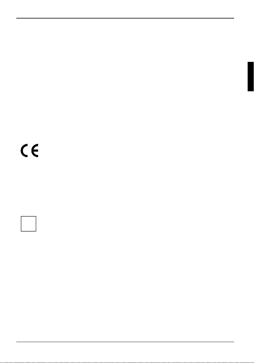
Ê Place the workstation on a flat, stable, nonslippery surface.
2
1
Ê Press the release button (1) and open the LED display panel (2).
12 A26391-K115-Z120-2-7619
Page 26
Unpacking and checking the delivery Preparing the workstation for use
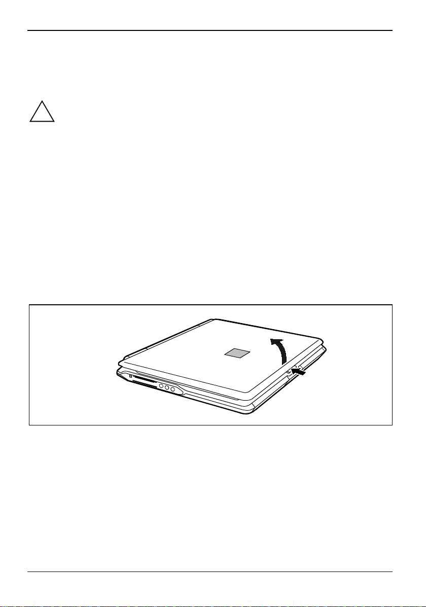
Connecting the power adapter and switching on the workstation
1
3
2
Use only the the power adapter provided.
!
Ê Plug the DC output connector on the power adapter into the DC input connector (DC IN) on the
workstation (1).
Ê Connect the power cable to the power adapter (2).
Ê Plug the power cable into the mains supply (3).
The power indicator
Ê Press the Suspend/Resume button (4), and releas e i t again.
The Suspend/Resume button functions like an ON/OFF switch.
The power-on indicator
on the workstation should illuminate. The batt ery will charge.
on the workstation lights up.
After switch-on a self -test (POST, Power On Self Test) is automatically carried out. Never
switch the workstation off during the self-test.
!
A26391-K115-Z120-2-7619 13
Page 27

Preparing the workstation for use Unpacking and checking the delivery
First-time software installation
Leave the external power adapter connected to your workstation during t he i ni tial
installation.
!
Once the installation has been started the workstation m ust not be switched off!
During installation the workstation may only be rebooted when y ou are requested to do
so!
Ê During installation, follow the instructions on screen.
Consult the operating system manual if there is anything unclear about the requested input data.
You will find further information about the system, drivers, utilities, updates, manuals etc.
on the "CELSIUS Mobile Driver CD" supplied.
i
14 A26391-K115-Z120-2-7619
Page 28
Working with the workstation
This chapter describes t he basics for operating your workstation.
The chapter on "Connecting external devices" has instruc tions on how to connect external devices
(e.g. mouse, printer) to t he workstation.
Please take note of the information in the chapter "Im port ant notes".
!
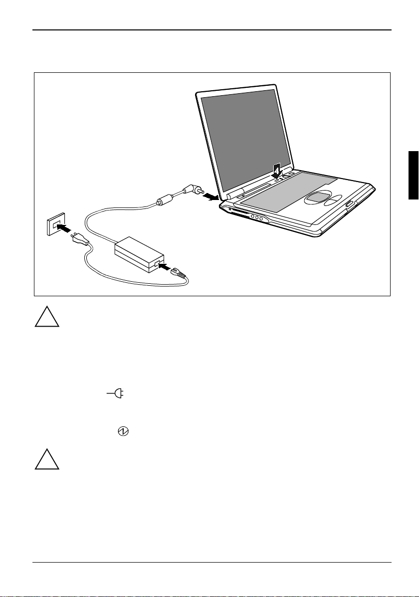
Switching the workstation on
2
1
Ê Press the release button (1) and open the LED display panel (2).
Ê Press the Suspend/Resume button to swi tch on the workstation (3).
The power-on indicator
on the workstation lights up.
You can configure the Suspend/ Resume button under Start - Settings - Control Panel -
Power Options - Power Options Properties.
i
A26391-K115-Z120-2-7619 15
If you have assigned a password, you must enter this when requested to do so, in order
to start the operating system password.
Page 29
Working with the workstation Switching off the workstation
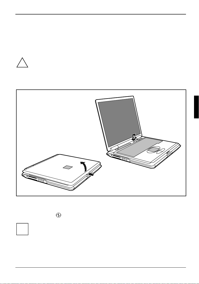
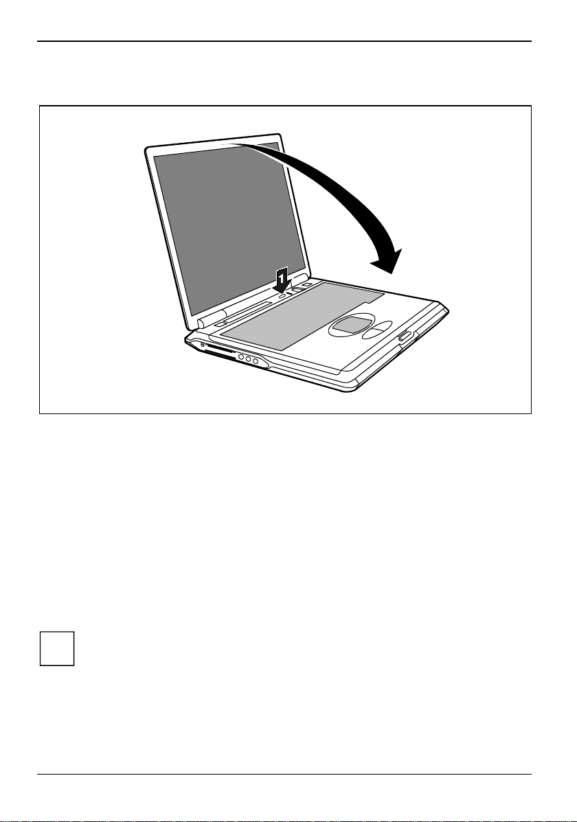
Switching off the workstation
2
Ê Shut down the operating system properly.
If the workstation is not switched off autom atically, press the Suspend/Resume button (1) and
release it again.
Ê Immediately press the Suspend/Resum e button again once, and hold it down for approxi m ately
four seconds until you hear an ac oustic signal.
The workstation is swit ched off.
Ê Close the LCD display of the workstation (2) so that it locks into place.
Switching off workstation via operating system
How you can switch off your workstation via the operat ing system is dependent on the settings of
the power-management feature. Addit i onal i nformation is contained in the section "Removing the
battery" in this chapter.
Save all open files before s wi t ching the workstation into the Standby mode to avoid data
loss when the workstati on rem ai n s switched off for a longer ti m e .
i
16 A26391-K115-Z120-2-7619
Page 30
Indicators Working with the workstation
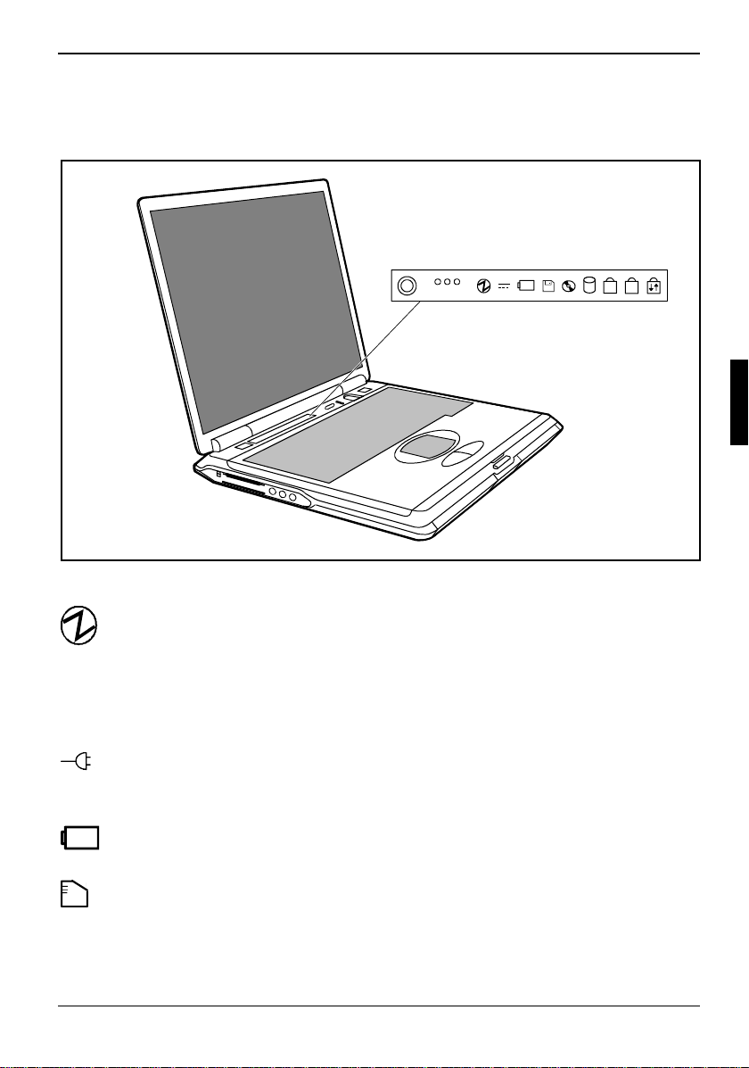
Indicators
The following icons appear in the dis play field of your workst ation:
A1
The meanings of the symbols are as follows:
Power-on indicator
· The indicator lights up:The workstation is on.
· The indicator flashes (1 second on / 1 second off):
The workstation is in energy-saving mode.
· The indicator is dark:
The workstation is swit ched off.
Power indicator
The power adapter is supplying power to the workstation.
07%
1
A26391-K115-Z120-2-7619 17
Battery indicator
The battery charge state is indicated in the status i ndi cator panel.
Indicator PC card 1
The indicator lights up when a PC card di sk in slot 1 is being accessed.
You must not remove the P C c ard from the slot when this indi cator is lit.
Page 31

Working with the workstation Indicators
2
CapsLK
ScrLK
NumLK
Indicator PC card 2
The indicator lights up when a PC card di sk in slot 2 is being accessed.
You must not remove the P C c ard from the slot when this indi cator is lit.
Hard disk indicator
The indicator lights up when the hard disk drive is being acces sed.
Floppy disk drive indicator
The indicator lights up when a floppy disk in the floppy dis k drive is being accessed.
You must not remove the f l oppy disk from the floppy di sk drive when this indicator is
shown.
Optical drive indicator
The indicator is lit when the CD/DVD in the optical drive i s being accessed.
You must not remove the CD/ DVD from the drive when this indi cator is lit.
CapsLK indicator (Caps Lock)
The Ï key has been pressed. A l l the characters you type appear i n uppercase. In the
case of overlay key s, the character printed on the upper l ef t of the key appears when that
key is pressed.
Scroll indicator (Scroll Lock)
The [Scr] key has been pressed. The effect this key has varies from programme to
programme.
NumLK indicator (Num Lock)
The key combination [Fn] + [Num LK] has been pressed. The numbers on the lower left
on keys in the integrated numeri c keypad are enabled.
18 A26391-K115-Z120-2-7619
Page 32

Keyboard Working with the workstation
Keyboard
The following description of keys refers to Windows. Additional functions s upported by the keys are
described in the relevant manual s supplied with your applicat i on program m es.
The figure below shows how to acces s the different characters on keys with overlaid f unctions. The
example applies when the CapsLK i ndi cator is not lit.
7
7/{
Alt Gr
NumLk
7/{
7
7
7
7/{
Backspace key
The Backspace key deletes the character to the left of the cursor.
Tab key
The Tab key moves the cursor to the next tab stop.
Enter key (return)
The enter key terminates a c om m and l i ne. The command you have entered is
executed when you press this key.
Caps Lock key
The Caps Lock key activates uppercase mode (CapsLK indi cator lit). The Caps
Lock function causes all the characters you type to appear in uppercase. In the
case of overlay key s, the character printed on the upper l ef t of the key appears
when that key is pressed.
To cancel the Caps Lock function, simply press the Caps Lock key again.
Shift key
The Shift key causes uppercase characters to appear. In the case of overlay keys,
the character on the upper left of the keycap appears when that key i s pressed.
Alt Gr key
The [Alt Gr] key causes the characters i n t he l ower middle of the keycap to appear
(e.g. { in the case of the [7] key shown on the example keyboard).
7/{
Alt Gr
Fn
7/{
7
A26391-K115-Z120-2-7619 19
Page 33

Working with the workstation Keyboard
Fn
Fn key
The [Fn] key enables the spec i al functions indicated on ov erl ay keys (see "Key
combinations").
If the external keyboard does not feature an [Fn] key, you can simultaneously press
the [Ctrl] + [Alt Gr] keys or the [Ctrl] + [Alt] keys.
Cursor keys
The cursor keys move the cursor in the direction of the arrow, i.e. up, down, left, or
right.
Break
Pause
Pause key
The [Pause] key temporarily suspends display output. Output will resume when you
press any other key.
Start key
The Start key invokes the Windows Start menu.
Menu key
The Menu key invokes the m enu f or the marked item.
Numeric keypad
/
(
7890
{
[
UI OP
1
J
K
)
=
]
}
789 *
456-
2
L
Ö
123+
M
;
:_
µ, . -
0/
.
1 = Characters enabled when NumLK indi cator is not lit (see "Indicators").
2 = Characters enabled when NumLK indi cator is lit (see "Indi cators").
If the numeric keypad is enabled (NumLK indicator is li t) and you hold down the [Fn] key, you can
output the characters print ed i n bl ue on the bottom right of the key s.
20 A26391-K115-Z120-2-7619
Page 34

Keyboard Working with the workstation
Key combinations
The following description of key combinations refers to functions when using Microsoft Windows.
Some of the following key combinations may not function in other operating systems and with some
device drivers.
Other key combinations are described in the relevant manuals supplied with your application
programmes.
Key combinations are perfo rm ed as follows:
Ê Press and hold the first key in the combination.
Ê While holding the first key down, press t he ot her key or keys in the com bi nat i on.
If the external keyboard does not feature an [Fn] key, you can simultaneously press
the [Ctrl] + [Alt Gr] keys or the [Ctrl] + [Alt] keys.
i
F3
+
Fn
Enlarge MS-DOS screen
This key combination enlarges the screen in the MS-DOS mode to the fullscreen mode or switches it back to the normal display mode.
F4
+
Fn
Switch internal touchpad on/off
This key combination enables and disables the touchpad function.
To do this, set the setting Internal Pointing Device to Auto Disabled in the BIOS
Setup in the menu Advanced - Keyboard/Mouse Features.
F5
+
Fn
Switch Speed Skp© mode on
This key combination switches between the possi bl e speed Skp© modes:
- Maximum power
- Battery-optimised power (reduced process speed in battery m ode)
F6
+
Fn
Switching the loudspeakers on/off
This key combination s wi tches your notebook's int egrated loudspeakers off and
on.
F7
+
Fn
F8
+
Fn
F9
+
Fn
F10
+
Fn
Increasing the volume
This key combination raises the volume of the integrated loudspeakers.
Reducing the volume
This key combination reduc es the volume of the integrated l oudspeakers.
LCD off
This key combination switches off the LCD screen to save power.
Switching between internal and external screen
If an external monitor is connected, the monitor on which the output is to be
displayed can be select ed wi t h this key combinati on. You can opt to use:
· just the workstati on' s LCD screen
· just the external monit or
· both the LCD screen and the external m oni tor.
F11
+
Fn
Increasing screen brightness
This key combination increases screen brightness.
A26391-K115-Z120-2-7619 21
Page 35

Working with the workstation Keyboard
F12
+
Fn
+
Ctrl
Ctrl
Decreasing screen brightness
This key combination dec reases screen brightness.
Halting the current operation
C
This key combination can be used to halt an operation instant l y without
clearing the keyboard buffer.
+
Alt Del
Backtab (Shift+Tab)
This key combination m oves the cursor back to t he previous
tabular stop.
Carrying out a warm boot
Warm boot
This key combination res tarts the workstation. Fi rst hold down
the [Ctrl] and [Alt] k ey, and then press the [Del] key. With
Windows 98, Windows 2000, Windows ME and Wi ndows NT
Task Manager appears first. Then you must press all three
keys again to re-boot.
22 A26391-K115-Z120-2-7619
Page 36

Keyboard Working with the workstation
Preparing the removable radio keyboard for use
Before using your CELSIUS Mobile H workstation, you must fit or connect a battery in the
removable keyboard. You do this as follows:
2
1
1
Ê Lift the keyboard at the two positions i ndi cated (1).
Ê Remove the keyboard in the direction of the arrow (2).
Ê Turn the keyboard over (3).
Ê Open the battery compartment at the rear of
1
the keyboard.
Ê Lift off the battery cell cover.
3
A26391-K115-Z120-2-7619 23
Page 37

Working with the workstation Keyboard
Ê Plug the battery connector into the connec tor in the battery compartm ent .
Ê Close the battery compartment.
Ê Hold the keyboard at an angle and ensure
that the pins (1) fit int o the matching
recesses.
1
1
24 A26391-K115-Z120-2-7619
Page 38

Keyboard Working with the workstation
Operating the removable radio keyboard for use
The keyboard can be removed as desc ri bed above.
The keyboard is permanently li nked to the workstation by m eans of a wireless connection. The right-
hand indicator on the keyboard light s as soon as a wireless c onnection is established. No keyboard
input is possible until the indicator lights. Oc casionally it can take up to 15 seconds to establi sh a
connection (normally 2 to 5 seconds).
The battery indicator is on when the battery is charging. The battery is charged only when the
keyboard is attached to the workstation. The battery i ndicator flashes if t he bat tery is low and the
keyboard is removed. Re-att ach the keyboard so that the bat tery can recharge.
Place the keyboard on the devi ce as often as possible so that the battery can be charged.
i
1
A26391-K115-Z120-2-7619 25
If you cannot establi sh a wireless connection
between the keyboard and the workst ation,
press the Reset button on the rear of the
keyboard (hole on the rear of the keyboard).
Page 39

Working with the workstation Keyboard
Switching the keyboard on and off
Ê Switch the keyboard ON or OFF with the ON/OFF switch.
Switch off the key borad whenever you do not intend to use it f or a prol onged peri od of time or whilst
on board a flight.
Operating the keyboard without a radio connection
Since the removable keyboard i s operated by a radio connection, your workstation may
only be switched on during a flight if you operate the workstat ion without a radio
!
connection in the way desc ri bed.
Ê Connect the PS/2 lead cable supplied to the right -hand port on the keyboard and to the
CELSIUS Mobile Workst ation.
26 A26391-K115-Z120-2-7619
Page 40

Keyboard Working with the workstation
A
Indicators on the keyboard
A1
BT
22
NumLK indicator (Num Lock)
1
Scroll indicator (Scroll Lock) Rechargeable battery indicator keyboard
BT
Radio connection
CapsLK indicator (Caps Lock)
Rechargeable battery indicator keyboard
Shows how much charge the battery has left.
· The indicator lights up:
The battery is charging.
· The indicator flashes:
The battery is nearly empty.
Place the keyboard on the workstation again so that the battery can be recharged.
1
NumLK indicator (Num Lock)
The key combination [Fn] + [Num LK] has been pressed. The numbers on the lower left
on keys in the integrated numeri c keypad are enabled.
CapsLK indicator (Caps Lock)
A
The Caps Lock key has been pressed. All the characters you type appear in uppercase.
In the case of overlay keys, the character printed on the upper left of the key appears.
Scroll indicator (Scroll Lock)
The [Scr] key has been pressed. This key has varies from programme to programme.
BT
Radio connection indicator
· The indicator lights up:
The radio connection is acti ve.
Keyboard input with touchpad and touchpad buttons is only possible if the indicator is lit.
A26391-K115-Z120-2-7619 27
Page 41

Working with the workstation Keyboard
Touchpad and touchpad buttons
The touchpad enables you to move t he m ouse pointer on the screen. The two touc hpad buttons
allow the selection and exec ution of commands. They c orrespond to the buttons on a conventi onal
mouse.
1
2
1 = Touchpad 2 = Touchpad buttons
Moving the pointer
Ê Move your finger on the touchpad.
Selecting
Ê Tap the touchpad once or press the left button once.
Executing a command
Ê Tap the touchpad twice or press the left button t wi ce.
Dragging an object
Ê Move the pointer to the item you wish to s el ect.
Ê Select the desired object, and leave your f i nger on t he touchpad.
Ê Drag the object to the desired position.
Ê Lift your finger from the touchpad.
28 A26391-K115-Z120-2-7619
Page 42

Display setti ngs Working with the workstation
Display settings
Setting the desktop area
You can change the screen resolution under Start - Settings- Control Panel - Display - Settings and then
selecting from the Resolution fiel d.
Adjusting the font size
Under Start - Settings - Control Panel - Display - Settings you can choose between a larger and a
smaller font in the Font size field.
Adjusting the speed of the mouse pointer
You can change the speed of the mous e poi nter under Start - Settings - Control Panel - Mouse and
clicking on the Motion tab.
Setting the display brightness
You can adjust the brightnes s of your LCD screen with the ke ys [Fn] and [F12] or [Fn] and [F11]:
With [Fn] and [F12], screen brightness will be reduc ed and with [Fn] and [F11] increased.
Synchronising the display on the LCD screen and an external monitor
Your workstation supports the simultaneous displ ay on the LCD monitor and an external monit or. If
the picture does not appear correctly on the LCD monitor, press t he key combination [Fn] + [F10]
several times, or swi tch the external monitor off and then on again. This achieves good picture
synchronisation.
A26391-K115-Z120-2-7619 29
Page 43

Working with the workstation Battery
Battery
The battery is one of the mos t i mportant components of your workstation. When not plugged into a
mains outlet, the workstation runs on its built -i n battery. You can increase the life of the battery by
caring for the battery properly . The average battery life is around 500 c harge/discharge cycles.
You can extend the battery l i fe by taking advantage of the available energy saving funct i ons.
Only use batteries releas ed f or your workstation.
!
Take care not to drop the batteries or otherwise damage their casing (f ire risk).
If the rechargeable batteries are defective, they must not be used.
Do not touch the contacts of the batteries.
Never interconnect the positive and negative terminals of a battery.
Used batteries must be disposed of in accordance with local regulations (special waste).
Observe the information on battery storage in the chapter "I m portant notes".
Performing the battery learning cycle
The battery contains elec tronics that continuous l y monitor the battery charging l evel and display the
current charging level. To compensate for measuring errors in the el ectronics, and because t he
chemical properties of t he battery change over time, t he el ectronics must be recal i brated regularly.
This calibration is carried out using a battery learning cycle. Using the battery learning cycle ensures
that the maximum batt ery capacity can always be used. During the learning cycle a defined charging
cycle is carried out.
The battery learning cycle lasts between four and six hours and must not be aborted.
During this period you can not work wi th the workstation!
i
Ê Restart the workstation (switchi ng On/Off or warm boot).
The following display briefly appears on the screen during start -up:
<ESC> Diagnostic screen <F12> Boot Menu <F2> BIOS Setup <F6> Battery
learning
Ê Press function key [F6].
The learning cycle is started. When the learning cycle is ended, a corresponding message is
displayed.
30 A26391-K115-Z120-2-7619
Page 44

Battery Working with the workstation
Charging the battery
The battery indicator displ ays the remaining battery c harge (see the section "Indicators"). When you
switch on the workstation, it takes a few s econds before the battery st atus is displayed.
You can charge the battery by connecting the workstat i on t o the power adapter (see "Connecting
the power adapter and switching on the work station").
The battery can only be charged when the am bi ent temperature is between 5°C and max. 35°C.
With the workstation switched on and off, the battery will completely recharge in approximately three
to four hours.
Work in the battery mode until an acoustic warning prompts y ou to recharge and the battery
indicator begins to flas h. The workstation battery s houl d not be charged before this point.
If you do not connect the power adapter within five minutes of the signals described above, your
workstation automatically switches it self off.
Monitoring charging time
The remaining battery charge is i ndi cated by the battery sy m bol i n the status indicator panel (see
the section "Indicators"). When you switch on the workstation, it t akes a few seconds before the
battery status is displayed.
During mobile operation you can also use a "battery charge meter" f or energy-saving monitoring
under Windows.
A battery icon is s hown i n the taskbar. When you positi on the cursor on the battery ic on, the battery
charge level is display ed wi th a blue status bar. This blue bar progressively decreases as the battery
discharges.
Inserting and removing the battery
Only use batteries releas ed f or this workstation.
!
Never use force when inserting or rem oving a battery.
Make sure that no foreign objects enter the slots.
Ê Switch off the workstation.
Ê Place the workstation on a flat surface.
Ê Open the LCD display panel.
A26391-K115-Z120-2-7619 31
Page 45

Working with the workstation Battery
Removing the battery
1
2
Ê Push the slide in the direction of the arrow up to the stop (1).
Ê Pull the battery out of the casing in t he di rection of the arrow (2).
32 A26391-K115-Z120-2-7619
Page 46

Battery Working with the workstation
Installing the battery
1
2
Ê Push the slide in the direction of the arrow up to the stop (1).
Ê Position the battery at the edge of the casing (2) and then press it into the workstation.
A26391-K115-Z120-2-7619 33
Page 47

Working with the workstation Using the power-management features
Using the power-management features
The workstation uses less power when the power management features are enabled. You will then
be able to work longer when using the battery before having to recharge it.
If you are connected to a network or use the integrated modem, P C LA N card, or PC
modem card, we advise against enabling an energy saving mode. This could lead to an
i
interruption of your network c onnection.
When not using the workstati on f or l ong peri ods of time, first end the energy saving mode,
then switch off the workstation. Never swit ch off the workstation wi th the
Suspend/Resume button while the workstation is in one of the energy-saving modes.
If your workstation i s in an energy-saving mode mode:
· Do not connect any external peri pheral devices.
· Do not disconnect any external peripheral devices.
· Do not attempt to switch the workstation on if t he bui l t-in battery is flat.
· Do not change or remove the floppy disk, if inserted.
· Do not add or remove RAM.
· Do not add or remove a PC card.
· Do not replace or remove the battery .
34 A26391-K115-Z120-2-7619
Page 48

Using the power-management features Working with the workstation
r
Energy-saving modes of workstation
You can set two energy-sav i ng m odes with your workstation.
In the Suspend mode (Suspend to DRAM/Standby) all current data (active program mes, files) are
buffered in the main memory, and i n the Save-to-Disk mode (Save to Disk/HibernateMode) all current
data are saved on the hard disk. Then the workstation is switched off. After the workstation is
switched on, you can continue working exactly where y ou l eft off before.
Operating systems with ACPI (Windows 98, Windows ME und Windows 2000)
For operating systems with ACPI you can set the energy-saving functions under Settings -
Control Panel - Power Management (e.g. Standby, Hibernate mode and LCD off).
i
Changing settings
Ê Double-click on the My Computer symbol.
Ê Double-click on the Control Panel symbol.
Ê Double-click on the Power management symbol in the Control Panel window.
The Properties dialogue field appears.
Ê Adjust the setting to your needs.
Ê Click on OK to save the settings.
You can configure the Suspend/ Resume button and the lid switc h i n the Settings tab unde
Settings – Control Panel – Power Management.
Settings for energy-saving functions in the BIOS Setup are not t aken into account by
operating systems with ACPI.
With Windows 2000 and Windows ME the def aul t setting for Hibernate mode is Disabled.
i
With Windows 98 please read the chapter "PHDISK (for Windows 98 and Windows NT
only)".
Additional information on thi s service programme is c ontained in the help function of Windows 98
and Windows 2000.
A26391-K115-Z120-2-7619 35
Page 49

Working with the workstation Using the power-management features
Operating systems with APM (Windows 95, Windows NT with APM extensions)
For operating systems with APM (Advanced Power Management) you can set the energy-
saving functions in the BIOS Setup (e.g. Suspend to RAM, Save to Disk, LCD off etc.).
i
Setting energy-saving modes
Ê Call the BIOS Setup.
Ê Set which energy-saving mode you want to use in the Power menu.
Ê Set the Auto Suspend Timeout parameter in the Power menu to a time period after which the
workstation is to be s wi t ched into the energy-saving mode.
Suspend to DRAM
In this mode the current dat a i n the main memory (DRAM) is stored. The data is stored for as l ong
as the workstation is supplied with energy. If the battery is full, the data is stored for a matter of
days. Without a battery and without a power supply the current dat a is lost.
Save to Disk
So that the current data can be saved, sufficient m em ory must be available on the hard dis k. If the
operating system Windows NT or OS/2 Warp is used, a Sav e-t o-Di sk partition must be c reated on
the hard disk (see manual for res pective operating system).
In this case also see the section "PHDISK (for Windows 98 and Windows NT only)".
36 A26391-K115-Z120-2-7619
Page 50

Using the power-management features Working with the workstation
PHDISK (for Windows 98 and Windows NT only)
The PHDISK service program m e reserves the memory spac e requi red for the use of Save-to-Disk
mode. The programme creates a file for saving the main memory c ontents and the system register
when your notebook is switc hed over to Save-to-Disk mode. The position of the first and l ast free
sectors are saved in t he " CM OS" after running this programme.
Additional power-management features
Closed cover switch
When you close the LCD display panel , the workstation switc hes into Standby mode. Opening the
LCD display panel ends Standby mode.
Ê Set the value On in the BIOS Setup in the Power - Advanced Features menu for the Lid Closure
Ê If the energy-saving mode is to be ended again by fol di ng up the LCD screen, then also set the
You will find a description of how to use the PHDISK programme on our internet page:
www.mobile-cd.de. Select Tipps &Tricks - PHDISK Suspend to Disk.
i
- Run PHDISK after you have i nstalled or removed memory modules.
- Run PHDISK after you have i nstalled or restored Windows NT.
- Run PHDISK after you have repl aced your hard disk.
- Run PHDISK if you have received a BIOS error message in conjunction with Save-to-Di sk
mode during the self test (P OS T).
In Windows NT the PHDISK service programme is not supported by the NTFS file system.
i
In Windows 2000, Windows Me and Windows X P the required memory space on the hard
disk is not reserved until you make the required Hibernate mode settings under Settings Control Panel - Energy Options.
Suspend parameter if your workstation i s to go into the energy-saving m ode when the lid is
folded down.
LidOpen Resume parameter to On.
Power Button
You can configure the Suspend/ Resume button.
If you want to use the Sus pend/Resume button as an ON/OFF switch, set the Power Button
parameter to Power Off in the Power - Advanced Features menu in the BIOS Setup.
Standby Timeout
With this mode the LCD screen and i nternal components automatically switch off af ter a defined
period of time. Any act i vity automaticall y returns the workstation to normal operation.
Hard Disk timeout
With this mode the motor of t he hard di sk drive is switc hed off as soon as no activ i t y with the
keyboard or the pointing device, or any other input or output acti vity takes place f or a time period
defined in the BIOS Setup.
This parameter is set in t he Po wer m enu i n the BIOS Setup. When the hard disk is acc essed, the
motor of the hard disk drive i s automatically swi tched on again.
A26391-K115-Z120-2-7619 37
Page 51

Working with the workstation Hard disk
Hard disk
The hard disk is the most i m port ant storage medium of your works tation. You can work consi derabl y
faster and more efficient l y if you copy applicat i ons and files from floppy di sks or CDs to your hard
disk.
When the hard disk is accessed, the hard disk indicator lights up
.
Inserting and removing modules
Modules can be optical driv es, additional hard disk or floppy disk drives or batteri es.
Only use modules released for this workstation.
!
Do not use force when installing or removing a module.
Make sure that no foreign objects enter the slots.
Ê Switch off the workstation.
Ê Place the workstation on a flat surface.
Ê Open the LCD display panel.
Removing modules
1
2
Ê Push the slide in the direction of the arrow up to the stop (1).
38 A26391-K115-Z120-2-7619
Page 52

Inserting and removing modules Working with the workstation
To remove the left-hand module, push the slide to the right. To remov e the right-hand
module, push the slide to t he l ef t.
i
Ê Remove the module the direction of the arrow (2).
Installing modules
1
2
Ê Push the slide in the direction of the arrow up to the stop (1).
To install the left-hand module, push the slide to the right. To i nstall the right-hand
module, push the slide to t he l ef t.
i
Ê Position the module at the edge of the casing (2) and then press it into the works tation.
Ê Release the slide (2).
A26391-K115-Z120-2-7619 39
Page 53

Working with the workstation Optical drives
Optical drives
Depending on the model, your workstation is equipped with a CR-ROM drive, a CD-RW dri ve, a
DVD-ROM drive or a combo drive (CD-RW/DVD).
This device contains a l i ght -em i tting diode, classif i ed according to IEC 825-1:1993:
LASER CLASS 1, and must not be opened.
!
Avoid touching the surf ace of a CD/DVD. Handle CDs/DVDs onl y by their edges!
Always store CDs/DV Ds in their cases. Thus you avoid dust contaminati on, scratches,
bending or other damage.
Protect your CDs/DVDs from dust, mechanical vibration and direct sunlight !
Avoid storing a CD/DVD in areas subject to high temperat ures or humidity.
You may use both 8-cm and 12-cm CDs/DVDs in the optical drive.
When using CDs/DVDs of poor qualit y vibrations and reading errors may occur.
Optical drive indicator
The indicator flashes when a CD/DVD is inserted. The indicator goes out when t he drive is
ready-to-operate. The indicator li ght s up when the drive is acces sed.
If the indicator does not go out after the CD/DVD is insert ed, and continues to flash, the
CD/DVD is probably damaged or dirty.
i
Inserting or removing a CD/DVD
The workstation must be s witched on.
Ê Push the insert/eject button.
The drive tray will open.
Ê Pull the drive tray completely out.
Ê Place the CD/DVD in the drive tray with t he label facing upwards.
or
Ê Take out an inserted CD/DVD.
Ê Push in the drive tray until you feel it l ock into place.
40 A26391-K115-Z120-2-7619
Page 54

Floppy Disk Drive Working with the workstation
Manual removal (emergency removal)
In the event of a power failure or damage t o the drive it may be necess ary to manually remove the
CD/DVD.
Ê Switch off the workstation.
Ê Push a pen or a piece of wire (such as a paper clip) into t he openi ng for manual ejection.
The drive tray is unlocked. You can now pull the drive tray out of the drive.
Please see the drive documentation for the location of t he opening for manual removal.
i
Floppy Disk Drive
Never clean the floppy dis k drive with cleaning disks. Any attempt would destroy the
read/write head in the disk driv e wi thin 20 seconds.
!
Make sure that no floppy disk is inserted in the f l oppy disk drive during transport.
Otherwise the eject button may break off and the floppy disk drive will be damaged.
Working with floppy disks
Follow the instructions supplied by the vendor of the floppy disks.
i
5
4
1
2
3
1 = Insertion direct i on
2 = Label area
3 = Write protection tab for a 1.44 Mbyte floppy disk
4 = Identificati on of a 1.44 MB floppy disk or wri te protect switch on a 120 MB f l oppy disk
5 = Eject button f or i nserted floppy disks
6 = Disk is writ e-protected
7 = Disk is not write-protected
A26391-K115-Z120-2-7619 41
6
7
Page 55

Working with the workstation 56k-Modem
To insert a diskette:
Ê Push the floppy disk into the drive in the insertion direction (1) until i t engages. The label
should be facing upward.
To remove a diskette:
Ê Push the eject button (5).
Protect the floppy disk against being overwritten or erased
Ê Slide the write-protect slider into position (6). The hole is now visible.
Deactivate write protection
Ê Slide the write-protect slider into position (7). The hole is now covered.
56k-Modem
Depending on the device version, a m odem may already be installed in your workstation. The 56k
modem supports all data com m uni cation applications, s uch as:
· Modem operation: High-speed downloads at up t o 56,000 bit/s (V.90). Downward-com patible to
V.34 modems.
· Fax mode: Transmitting and rec ei ving at up to 14,400 bit/s
· Simple country adaptati on wi th programme
The modem complies with the E U Di rective 91/263/EEC (Telecom m uni cations terminal equipment
directive) and has been checked in agreement with the guideline TBR-21.
The modem can be operated in the following c ountries:
Multifrequency (MFC) diali ng
Belgium, Denmark, Germany, Fi nl and, France, Greece, Great Britain, Hol l and, Ireland, Iceland,
Italy, Luxembourg, Norway , Austria, Portugal, Sweden, Switzerland and Spain.
Pulse dialing:
Belgium, France, Holland and It al y.
Also in: Poland, Slovenia, South Africa and Hungary .
42 A26391-K115-Z120-2-7619
Page 56

Connecting IEEE1394 (FireWire) Working with the workstation
Connecting workstation modem to telephone connection
3
1
2
Ê Connect the modem cable supplied to the country -specific telephone adapter (1).
Ê Connect the modem cable to the modem port of the work station (2).
Ê Connect the modem cable to your telephone wall soc ket (3).
Connecting IEEE1394 (FireWire)
Peripheral devices suc h as digital audio/video devic es or other high-speed devices c an be
connected via IEEE1394 (FireWire). Your workst at ion can be equipped with an IEEE1394 (FireWire)
connection, which operates at 400 Mbit per second, as an option.
Ê Connect the peripheral device to the IEEE1394 (FireWire) connection on the left -hand side of
your workstation.
A26391-K115-Z120-2-7619 43
Page 57

Working with the workstation PC cards
NOTE:
This device and its antenna(s) must not be co-located or operating in conjunction with
any other antenna or transmitter.
PC cards
Two PC card slots enable the notebook to operate two type II PC cards or one type III PC card
(CardBus or PCMCIA) .
Installing a PC card
Consult the documentation supplied by the PC card's manufacturer and follow the
instructions provided.
!
Never use force when inserting or rem oving a PC card.
Make sure that foreign objects do not fall into the PC c ard slot.
Ê Insert the PC card, contacts fi rst, into the lower slot gui de. The labelled side of the PC card
should be facing upward.
Ê Gently push the PC card into the slot until you feel it click i nt o pl ace.
Consult the documentation supplied with the PC card for inf orm ation on how to install the
necessary device drivers.
i
For further information refer to the information files (e.g. *.TXT, *.DOC, *.WRI or *.HLP)
provided on the PC card driver diskette or the information in t he operat i ng system manual.
You can push the PC card slot ej ect buttons down flush int o t he case. Press the ejec t
buttons until they snap i n.
44 A26391-K115-Z120-2-7619
Page 58

SmartCards Working with the workstation
Removing a PC card
2
1
Ê Press the eject button (1). It will project further out of the workstation's case. If the eject buttons
are pushed in flush with the workstation casing, they must first be snapped out . Press the eject
buttons until they snap out.
Ê Slide the PC card out of the workstation (2).
SmartCards
The SmartCard slot permits the operation of a SmartCard.
A26391-K115-Z120-2-7619 45
Consult the documentation supplied by the SmartCard's m anuf acturer and follow the
instructions provided.
!
Never use force when installing or removing a S m art Card.
Make sure that foreign objects do not fall into the Sm art Card slot.
Page 59

Working with the workstation SmartCards
Inserting a SmartCard
Ê Insert the SmartCard, contacts f i rst, into the lower slot gui de. The labelled side of the
SmartCard must be facing upward.
Ê Gently push the SmartCard into the slot unti l you feel it click i nt o pl ace.
Consult the documentation supplied with the SmartCard for inf o rm at ion on how to install
the necessary devic e dri vers.
i
For further information refer to the information files (e.g. *.TXT, *.DOC, *.WRI or *.HLP)
provided on the SmartCard driver dis kette or the information in the operating system
manual.
46 A26391-K115-Z120-2-7619
Page 60

SmartCards Working with the workstation
Sliding out a SmartCard
1
Ê Slide the SmartCard out of its location (1).
A26391-K115-Z120-2-7619 47
Page 61

Working with the workstation Microphone and loudspeakers
Microphone and loudspeakers
1
2
1 = built-in microphone 2 = built-in loudspeakers
Your workstation contai ns a built-in microphone (1) and two loudspeak ers (2).
If you attach an external m i crophone, the built-in microphone is disabled. The internal loudspeakers
switch off when you att ach headphones or external loudspeakers to the audio jack.
48 A26391-K115-Z120-2-7619
Page 62

Fingerprint reader Working with the workstation
Fingerprint reader
The workstation is equipped wit h a fingerprint reader. Instead of enteri ng a user password, you can
also log on to the system with a fingerprint.
A26391-K115-Z120-2-7619 49
Page 63

Working with the workstation Property and data protection
Property and data protection
Your workstation enables y ou to protect your system and personal data against unauthorised
access in a number of ways. By combining these options, you can achieve m aximum protection for
your system.
Security functions under Windows
Under Windows you can activate a screen saver and protect it with a password. Only thos e users
who know the password can deactivate the screen saver and access any open files.
BIOS Setup security functions
The Security menu in BIOS Setup offers you various options for protecting y our personal data against
unauthorised access. By combining these options, you can achieve maxi m um protection for your
system.
Preventing unauthorised BIOS Setup entry
You can activate thi s protection by setti ng a supervisor or a user password in the Security menu
(Set Supervisor Password/Set User Password).
Preventing unauthorised system access
You can activate this protection by setti ng a password in the Security menu. In addition, you must
select the entry Enabled in the Password on boot field.
Preventing unauthorised access to the hard disk drives
You activate this prot ection when you set a hard disk passwords in the Hard Disk Securit y submenu
of the Security menu. To do this, set the entry HDD password to Enabled.
If set, the hard disk passwords are checked at each system startup, regardless of whether
Password On Boot is set to Enabled or Disabled.
Preventing unauthorised access to floppy disk drive
To activate this protection, select the v al ue Supervisor for the Diskette access field in the Security
menu.
50 A26391-K115-Z120-2-7619
Page 64

Property and data protection Working with the workstation
Setting passwords
A user password can only be set if a supervisor password has been assigned. The supervisor or
user password prevents unauthorised callup of BIOS Setup. Only those who know one of the two
passwords can call BIOS Setup.
With the supervisor pass word you have access to all functions of the BIOS Setup. Wit h t he user
password you only have acc ess to part of the functi ons of the BIOS Setup.
The user password prevents unauthorised access to your workstation. With the user pas sword you
can prevent booting of the operating system. Only those who know the user password can access
the system.
Passwords can be up to eight characters long. All alphanumeri cal characters can be
used; no differentiation i s made between upper-case and lower-case.
i
Passwords are not display ed as they are entered.
If you have forgotten a password, contact your system administrator or contact our
customer service centre.
To set or change a password, proceed as follows:
Ê Call BIOS Setup and select the Security menu (see chapter "Settings in BIOS Setup"). You must
additionally change into the Hard Disk Security submenu for the hard di sk passwords.
Ê Mark the Set Supervisor Password or Set User Password field and press the Enter key.
You are asked to enter a password:
Enter new Password:
Ê Enter the password and press the Enter key.
You are asked to confirm t he password:
Re-enter new Password:
Ê Enter the password again and press the Enter key.
The new password is saved.
Notice: Changes have been saved [continue]
Ê To prevent booting of the operating system, mark the Password on boot field and select the
value Enabled.
If you do not want to make any other settings, you can exit BIOS Setup.
Ê Select the option Exit Saving Changes in the Exit menu.
The workstation is rebooted and the new password is effectiv e.
A26391-K115-Z120-2-7619 51
Page 65

Working with the workstation Property and data protection
Canceling passwords
Supervisor / User password
If you cancel the supervisor password, you automat i cally deactivate t he user password.
i
To cancel a password (without s etting a new password):
Ê Call BIOS Setup and select the Security menu (see chapter "Settings in BIOS Setup").
Ê Mark the Set Supervisor Password or Set User Password field and press the Enter key.
You are asked to enter a password:
Enter new Password:
Ê Press the Enter key twice.
Ê Select the option Exit Saving Changes in the Exit menu.
The workstation is rebooted and the password is cancelled.
Hard disk password
To cancel a password (without s etting a new password):
Ê Call BIOS Setup and select the Security menu (see chapter "Settings in BIOS Setup").
Ê Change into the submenu Hard Disk Security.
Ê Set the entry HDD password to Disabled in the Hard Disk Security submenu.
Ê Select the option Exit Saving Changes in the Exit menu.
The workstation is rebooted and the password is cancelled.
Removable keyboard
To protect your workstati on from unauthorised users, you can also remove the keyboard.
52 A26391-K115-Z120-2-7619
Page 66

Property and data protection Working with the workstation
Kensington Lock
a = Kensington Lock
You can protect your works tation from theft with t he Kensington Lock device (a) and a K ensington
MicroSaver.
A26391-K115-Z120-2-7619 53
Page 67

Page 68

Connecting external devices
Under all circumstances, please observe the safety notes provided in the "I m portant
notes" chapter.
!
Read the documentation on the external device before connecting it.
Do not connect or disconnect cables during a thunderstorm.
Do not pull on the cable when disconnec ting a cable. Always take hold of the actual plug.
Adhere to the order described in the fol l owi ng when you connect external devices to the
workstation or separate them from the workstation:
Connecting devices to the workstation
1) Turn off all power and equipment switches.
2) Remove all power plugs from the mains outlets.
3) Connect all the cables to the work station and the external devices.
4) Plug all data communication cables into the utility sockets.
5) Plug all power cables into the mains supply.
Disconnecting devices from workstation
1) Turn off all power and equipment switches.
2) Remove all power plugs from the mains outlets.
3) Unplug all data communication cables from the utility sockets.
4) Disconnect all the cables from the workstation and the ex ternal devices.
Ports
DC In
Connections on the rear
A26391-K115-Z120-2-7619 55
Page 69

Connecting external devices Ports
Line In
Connections on the left s i de
IR
Modem
LAN
Connections on the right side
56 A26391-K115-Z120-2-7619
Page 70

Connecting an external monitor Connecting external devices
The ports are marked with the foll owi ng symbols (or with simi l a r symbols):
LAN
LAN-port
(Local Area Network, for
Network connection)
PS/2 port (for keyboard or
mouse)
Parallel port Microphone connector
DC In
Port for power adapter
Headphones port
TV
Monitor port
TV out socket
(video output)
Serial port
Some of the external devices require special drivers (see the operating system and
external device document at i on).
i
IR
Infrared port
USB port
Modem port
Connecting an external monitor
An external monitor can be connected to the workstation. The screen controller in your workstation
supports extended SXGA resolutions of up to 1280x1024/60 Hz and 16 bi t colour depth.
· Using the [Fn] + [F10] key combinat i on you can switch back and f ort h between the external
monitor and the LCD screen.
· If your workstation is equipped wi t h a TFT monit or, you can display the same picture on the
external monitor and the LCD screen simultaneously.
Ê Switch off the workstation and the external monitor.
Ê Connect the external monitor to the monitor port on your workstation.
Ê First switch on the monitor and then the works t ation.
Setting the refresh rate for your external monitor
The refresh rate must be correctly set so that the image does not flicker.
Ê To change the refresh rate or resolution select the m oni tor type in the menu Start - Settings -
Control Panel - Display - Settings - Advanced - Monitor.
Ê Now select the Adapter tab.
Ê Adjust the refresh rate and then click Apply.
If the refresh rate set i s too high, the monitor may be dam aged. Please see the
documentation included with your monitor for the maximum possible refresh rate.
!
A26391-K115-Z120-2-7619 57
Page 71

Connecting external devices Connecting an external keyboard
Connecting an external keyboard
You do not need to switch off your workstation.
Ê Simply connect the external keyboard to the PS/2 port on your workstation.
Connecting an external PS/2 mouse
You do not need to switch off t he workstation.
Ê Simply connect the mouse to the PS / 2 port on your workstation.
Connecting a serial mouse
Ê Switch off the workstation.
Ê Connect the mouse to the parallel port on your workstation.
Ê Switch the workstation on.
Ê Run the mouse service programme under Start - Settings - Control Panel and select the General
tab.
Ê Select the correct mouse type.
Ê Restart the workstation.
Using the parallel port
Ê Switch off the workstation.
Ê Connect the data cable of the printer to the parallel port on the workstation.
Ê Plug the printer power cable into the mains outlet.
Ê First switch on the printer, then the works tation.
Using the serial port
Ê Switch off the workstation.
Ê Connect the data cable of the printer to the parallel port on the workstation.
Ê Plug the printer power cable into the mains outlet.
Ê First switch on the printer, then the works tation.
58 A26391-K115-Z120-2-7619
Page 72

Establishing an infrared connection Connecting external devices
Establishing an infrared connection
Using the infrared software for Windows, you can communic ate with another PC or printer equipped
with an infrared interface.
Before you can establis h an i nf rared connection, you must have activated the infrared
software. Additional information on the infrared interface is contained in the Windows help
i
in the Start menu under the topic " Infrared".
Configuring the infrared connection
By default, the mode for the infrared port is set to FIR ("Fas t IrDA Mode") in the BIOS Setup. If you
want to communicate with a system on which Windows ME is not running, you can change the
setting to IrDA. Please note that IrDA is the s l ower m ode and i s generally used on older computers.
Connecting USB devices
On the USB ports you can connect external devices that also have a USB port (e.g. a pri nter, a
scanner or a modem).
USB devices are hot-pluggable. Thi s allows cables from USB devices to be connected
and disconnected with the system switched on.
i
Additional information c an be f ound i n the documentation for the USB devices.
Ê Connect the data cable to the external device.
Ê Connect the data cable to a USB port .
Device drivers
i
The devices you connect t o the USB ports usually require no dri ver of their own, as the
required software is already inc l uded i n the operating system. However, if the USB device
requires its own software, pl ease install it from the data carrier provided with the USB
device.
A26391-K115-Z120-2-7619 59
Page 73

Page 74

Settings in BIOS Setup
In BIOS Setup you can set the system functions and the hardware configuration of the workstation.
The settings can only be c hanged via the keyboard.
When it is supplied, the work station is set to f actory default setti ngs. You can change these set t i ngs
in BIOS Setup. Any changes you make t ake effect as soon as you save and quit the BIOS Setup.
The BIOS Setup programme contains the fol l owi ng menus:
Main: for system settings as time, date, hard disk and monitor selection
Advanced: for system settings such as ports and keyboard
Security: for password set tings and safety func t i ons
Power: for setting the energy saving functions
Boot: for configuring the boot sequenc e
Info: for displaying the system configuration (e.g. processor and memory configuration)
Exit: to exit the BIOS Setup
Start BIOS Setup
Ê Restart the workstation (switchi ng On/Off or warm boot).
The following display briefly appears on the screen during start -up:
<ESC> Diagnostic screen <F12> Boot Menu <F2> BIOS Setup <F6> Battery
learning
Ê When this message appears, press the key [F2].
If a password has been assigned:
i
Ê Enter the password and press the Enter key.
If you have forgotten the password, contact your system administrator or contact our
Hotline/Help Desk.
Operating BIOS Setup
Press the [F1] key to display help on the operation of BIOS Setup.
The description of the indiv i dual settings is shown in the right-hand window of the BIOS
i
Setup.
You can revert to the default settings for the BIOS Setup menu you are c urrently in, by
using the [F9] function key.
Ê Use the cursor key å or ç to select the menu you wish to access to make changes.
Ê Press the Enter key.
The menu is displayed on the sc reen.
Ê Use the cursor key æ or è to select the field you wish to change.
Ê Press the space bar to confirm your sel ection.
Ê Press the [ESC] key to exit the selected menu.
Ê For future reference, make a note of the changes you have made (for example, in this m anual ).
A26391-K115-Z120-2-7619 61
Page 75

Settings in BIOS Setup
Exiting BIOS Setup
To exit BIOS Setup, select the Exit menu from the menu bar. You can then decide which s ettings you
want to save. The Exit menu offers the following options.
You must mark the required opti on and activate it with the Enter key.
Exit Saving Changes
Select Exit Saving Changes and Yes to save the current settings and exit the BIOS Setup. The device is
rebooted and the new settings com e i nto effect.
Exit Discard Changes
Select Exit Discard Changes and Yes to discard the changes you have made. The settings which were
in force when BIOS Setup was called remain effective. BIOS Setup is terminated and the device is
rebooted.
Load Setup Default
To revert all the menus of BIOS Setup to the default entries, select Load Setup Default and Yes.
Discard Changes
To load the values of all the menus of BIOS Setup that were in effect when BIOS Setup was called,
select Discard Changes and Yes. If you want to exit BIOS Setup with these settings, select Exit Saving
Changes and Yes.
Save Changes
To save settings wit hout exiting BIOS Setup, select Save Changes and Yes.
62 A26391-K115-Z120-2-7619
Page 76

Troubleshooting and tips
Take note of the hints in the chapter "Connecting external devi ces", when you connect or
disconnect cables.
!
If a fault occurs i n your workstation, try to eliminate it with the measures described in this chapter. If
you fail to correct t he probl em , proceed as follows:
Ê Make a note of the steps and the circums t ances that led to the fault . Also make a note of any
error messages displayed.
Ê Switch off the workstation.
Ê Contact your sales outlet or our Hotline/Hel p Desk.
Installing new software
When installing programmes or drivers, important files may be overwritten and modified. To be able
to access the original data in the case of any problems following installation, you should backup
your hard disk prior to inst al l at ion.
Saving and restoring system files
With "Microsoft Backup" you can create backup copies of your system files and restore the files. We
recommend that you create a bac kup copy of all important files after switchi ng on your workstation
for the first time.
Click on Start and select Accessories and System Tools.
Ê Click on Backup.
Ê Depending on whether you want to create a backup copy or rest ore t he files, select either the
Backup or the Restore tab.
Ê Follow the instructions on the screen.
Restoring the hard disk contents under Windows
Using the Windows Recovery CD and the CELSIUS Mobile Driver CD, you can restore the operating
system of your workstation.
During restoring the operating manual the contents of your hard disk will be overwritten. After this,
operating system, drivers and software utilities will be reinstalled. For this reason you should t ry to
save important data to a bac kup medium before you restore the hard disk contents.
Ê Insert the "Start-Disk for Windows " i nto the floppy disk driv e and switch the workstati on on.
Ê Follow the instructions on the screen.
Detailed PC knowledge is required for m anual partitioning.
i
Ê Insert the Windows Recovery CD into the opti cal drive.
Ê Start the Setup programme on the CD.
You must then reinstall all the drivers. Use t he " CE LSIUS Mobile Driver CD".
A26391-K115-Z120-2-7619 63
Page 77

Troubleshooting and tips
The workstation's date or time is incorrect
Ê Double-click on the clock in the tas k bar and adjust the time.
or
Ê Set the time and/or date in the BIOS Setup menu Main.
Battery indicator does not illuminate Battery is not installed or is defective
If the battery status indicator does not light up, either no battery is installed or there is no contact
between the workstation and the bat tery.
Ê Check whether the battery is installed correctly in its c ompartment.
It may be necessary t o repl ace the battery with a new one. When you di spose of used batteries,
please observe the safety instructions in the chapter "Important notes" .
The LCD screen of the workstation remains blank Monitor is switched off
Ê Press a key or enter the password
External monitor or television set connected
Ê Set the setting Display Settings to LCD BIOS-Setup in the menu Advanced - Video Features.
If the date and time are repeatedly i ncorrect when you switch on t he workstation, the
buffer battery that suppl i es the internal clock is dead.
i
Connect the workstation via its power adapter to a grounded mains out l et or install a fresh
battery. The buffer battery will take approximately two days to complete it s recharge.
Should the problem persist, pl ease contact our Hotline/Help Desk.
The workstation's LCD display is difficult to read Reflection
Ê Turn the workstation or alter the tilt of t he LCD di splay.
64 A26391-K115-Z120-2-7619
Page 78

Troubleshooting and tips
The external monitor stays blank
If your screen remains bl ank this may be due to the foll owi ng:
Monitor is switched off
Ê Switch the external monitor on.
Power saving has been activated (screen is blank)
Ê Press any key to continue.
Brightness is set too dark
Ê Adjust the brightness of the monitor.
The workstation has been configured to drive the internal LCD display
Ê Press the key combination [Fn] + [F10] (selecting internal/external dis pl ay).
The external monitor's power cable or data cable is not connected properly
Ê Switch off the external monitor and the work station.
Ê Check whether the power cable is plugged properly into the power adapt er and i nto the mains
outlet.
Ê Check whether the data cable is properly connect ed to the workstation and the ext ernal monitor
(if it is plugged in with a connector).
Ê Switch on the external monitor and the workst ation.
The external monitor is blank or the image is unstable
Two causes are possible: A n i ncorrect type has been selec ted for the external monitor or the wrong
screen resolution has been set for the application programme.
Ê Terminate the application programme with [Alt] + [F4].
If the fault continues to occur after ending the programm e, switch over to the workstation's internal
LCD screen with [Fn] + [F10]. Change the foll owi ng setting:
Ê Select Start - Settings- Control Panel - Display - Settings and then the screen resolution you
require in the Resolution field.
or
Ê Select the correct monitor under Start - Settings- Control Panel - Display - Settings - Advanced
Properties - Monitor - Modify.
A26391-K115-Z120-2-7619 65
Page 79

Troubleshooting and tips
The workstation does not start after switch on
If the workstation does not start after switch on, this may be due to one of t he following:
The battery is not installed correctly.
Ê Switch off the workstation.
Ê Check whether the battery is installed correctly in its c ompartment.
Ê Switch the workstation on.
The battery is dead
Ê Charge the battery.
Or
Ê Install a charged battery.
Or
Ê Connect the power adapter to the workstation.
The power adapter is not connected correctly.
Ê Switch off the workstation.
Ê Check whether the power adapter is connected correct l y to the workstation.
Ê Check whether the power cable is plugged properly into the power adapt er and i nto the mains
outlet.
Ê Switch the workstation on.
The workstation stops working
If the workstation stops working, this m ay have the following reasons:
The workstation is in Standby or Suspend mode
Ê Reactivate the workstation by pressing a key (Standby mode) or by switching it back on
(Suspend mode).
An application programme has caused the malfunction
Ê Close the application programme or restart the workstation by switchi ng i t On/Off or with a
warm boot.
The battery is dead
Ê Charge the battery.
Or
Ê Install a charged battery.
Or
Ê Connect the power adapter to the workstation.
66 A26391-K115-Z120-2-7619
Page 80

Troubleshooting and tips
The mouse does not work
If the connected mouse does not work, the following can cause it:
Incorrect setting in BIOS Setup
Ê Check the setting Hotplug in the BIOS Setup in the menu Advanced - Keyboard/Mouse Features.
The setting must be set t o Enabled.
Touchpad driver is not installed properly
Ê Deinstall the touchpad driver.
Ê Install the actual driver from the " CE LSIUS Mobile Driver CD".
Mouse driver is not loaded
Ê Check whether the correct mouse driver is properl y installed and is present bef ore the
application programme is started.
Detailed information can be found i n the User Guides for the mouse or application programme.
Mouse is not connected
Ê Switch off the workstation.
Ê Check that the mouse cable is correct l y connected to the workst ation.
If you use an adapter or extens i on l ead wi t h the mouse cable, check the connections.
Ê Switch the workstation on.
The floppy disk cannot be written
Ê Check whether the disk is OK and is not writ e-protected.
The printer does not print
Ê Make sure that the printer is switched on and i s on-line (see the manuals supplied wi th the
printer).
Ê Check that the cable connecting the workstation and the printer is connected properly.
Ê Check that the correct printer driver is i nstalled.
Ê Check in the BIOS Setup whether the Advanced - I/O Device Configuration field is set to Enabled
for the port you are using.
The respective entry in t he f i el ds of Serial Port or Parallel Port must match the setting in the
application programme under Windows.
A26391-K115-Z120-2-7619 67
Page 81

Troubleshooting and tips
Acoustic warnings
A beep sounds every few seconds
The battery is almost f l at.
Ê Charge the battery.
Error messages on the screen This section describes the error messages generated by t he BIOS-Setup. Error messages displayed
by the operating system or programmes are described in the relevant manuals.
CMOS Battery Bad
If the error message occurs repeatedly, then the buffer battery in the workstati on i s dead.
Ê Connect the workstation via its power adapter to a mains out let. The buffer battery will take
approximately two days to complete its recharge.
If the error message appears repeatedl y, please contact the pl ace of purchase or our
Hotline/Help Desk.
System CMOS checksum bad – Default configuration used
The system configuration information is incorrect.
Ê Restart the workstation.
Ê Enter the BIOS Setup programme by pressing [F2].
Ê Select the Exit menu in the BIOS Setup.
Ê Select the Default Setup entry and click on OK.
If the error message appears repeatedl y, please contact the pl ace of purchase or our
Hotline/Help Desk.
Insert system diskette and press Enter key to reboot
The operating system cannot be loaded or the hard disk contains no operating system or is not
formatted.
Ê Insert a system disk.
Ê Press any key to continue.
Invalid system disk - Replace the disk, and then press any key
The inserted disk is not a system disk or the inserted system disk is defective.
Ê Insert another system disk.
Ê Press any key to continue.
If you wish to boot from f l oppy disk:
Ê Insert a system disk.
Ê Press any key to continue.
Diskette drive A error
Ê Start the BIOS Setup and make sure that the parameter for fl oppy disk drive A has been set to
the format 1.44 Mbyte, 3 1/2 inch.
68 A26391-K115-Z120-2-7619
Page 82

Troubleshooting and tips
Extended memory failed at offset: xxxx Failing Bits: zzzz zzzz
When testing the extended memory an error has resulted at the address xxxx.
Ê Check whether the additional memory module has been ins erted correctly.
Should you receive this error m essage again, please contact your dealer.
Failure Fixed Disk n
The settings of the hard disk drive are incorrect.
Ê Start the BIOS Setup (IDE Adapter 0 Master submenu) and select the correct settings.
Fixed Disk address conflict Diskette Drive address conflict
There is an I/O address confl i ct.
Ê Start the BIOS Setup and check the corresponding settings.
Incorrect Drive A type - run SETUP
Ê Start the BIOS Setup and make sure that the parameter for fl oppy disk drive A has been set to
the format 1.44 Mbyte, 3 1/2 inch.
Keyboard controller error
Ê Switch off the workstation with t he Suspend/Resume button.
Ê Wait 3 - 5 seconds and switch on the workstat i on agai n.
If this error message appears agai n, please contact your point of sale or our Hotline/Help Desk .
Keyboard error
If you use an external keyboard:
Ê Check the connection and reboot the workstati on.
If this error message appears agai n, please contact your point of sale or our Hotline/Help Desk .
nn Stuck key
Ê Make sure that no key is pressed.
If this error message appears agai n, please contact your point of sale or our Hotline/Help Desk .
Operating system not found
Ê Check in the BIOS Setup whether your hard disk has been set c orrectly.
Ê Make sure that the operating system is installed on the corresponding drive.
A26391-K115-Z120-2-7619 69
Page 83

Troubleshooting and tips
Not enough Save-to-Disk partition or file exists on Fixed Disk - Save-to-Di sk feature i s
disabled.
The Save-to-Disk mode is not available to you, as no mem ory space has been assigned to t hi s
mode.
Ê Use the PHDISK service programme to ass i gn the memory space required for thi s mode.
Press <F1> to resume, <F2> to SETUP.
This error message appears if an error oc curs during the self-test before starting the operating
system.
Ê Press the [F1] function key to st art the operating system.
Ê Enter the BIOS Setup programme by pressing [F2].
Previous boot incomplete - Default configuration used
Due to an error during the previous system boot, default values were used for certain sett i ngs.
Check the BIOS Setup and the settings .
Ê Press the [F1] function key when prompted to do so.
Real Time clock error
Ê Contact your sales outlet or our Hotline/Hel p Desk.
nnnnK Shadow RAM failed at offset: xxxx Failing Bits: zzzz
Ê Contact your sales outlet or our Hotline/Hel p Desk.
System battery is dead - Replace and run SETUP
Ê Contact your sales outlet or our Hotline/Hel p Desk.
System cache error - Cache disabled
Ê Contact your sales outlet or our Hotline/Hel p Desk.
nnnnK System RAM failed at offset: xxxx Failing Bits: zzzz
Ê If you have installed a DIMM, you s houl d rem ove the module and reboot the workstat i on.
If the error message is no longer di splayed, the error concerned is DIMM-related. Should you
receive this error mess age agai n, please contact your dealer.
System timer error
Ê Contact your sales outlet or our Hotline/Hel p Desk.
70 A26391-K115-Z120-2-7619
Page 84

Memory expansion
The workstation must be switc hed of f when installing/removing the memory modules and
may not be in the Suspend mode.
!
So that the current data can be saved in the Save to Disk suspend mode, sufficient
memory space must be av ai l abl e on the hard disk (at least the s i ze of the main
memory +16 Mbytes).
Install only memory expansions that satis fy the requirements and rules gov erni ng safety,
RFI and electromagnetic compatibility and relati ng t o t elecommunications terminal
equipment (see the chapter "Im portant notes").
Use only memory expansi ons which have been released for your workstation (128, 256,
and 512 Mbyte modules, SD RAM , JEDEC 144 pin SO DIMM, 3.3 V).
Never use force when installing or removing memory modules.
Make sure that foreign objects do not fall into the memory module compartment.
The main memory of your workstation can be expanded to a maximum of 512 Mbyte with another
memory module. The workstation will not start without memory modules, as no fix ed main memory
is installed.
Removing and installing memory extension
Please note the information provided in t he "Not es on installing and removing boards and
modules" section in t he chapter "Important notes".
!
Ê Switch off the workstation and the connected peripherals.
Ê Close the LCD display of the workstation so that it locks into place.
Ê Unplug the power adapter from the mains outlet.
Ê Remove the battery (see "Removing the battery").
Ê Disconnect all cables connected to workstation.
Ê Place the workstation bottom-up on a flat surface.
Removing cover
Ê Remove the screw (1).
1
3
Ê Lift the cover off the workstati on i n the
direction of the arrow (2).
Ê Pull off the cover from the workstation in the
2
A26391-K115-Z120-2-7619 71
direction of the arrow (3).
Page 85

Memory expansion
Installing memory modules
1
2
3
1
Ê Carefully push the two mounting clips outwards (1).
Ê Insert the memory module, contacts first, into the s l ot (2).
Ê Carefully push the memory module downwards until y ou feel it latch into plac e (3).
Removing memory modules
1
3
2
1
Ê Carefully push the two mounting clips outwards (1).
The memory module will flap upward (2).
Ê Pull the memory module out of its slot (3).
72 A26391-K115-Z120-2-7619
Page 86

Memory expansion
Mounting the cover
3
1
2
Ê Refit the battery.
Ê Place the workstation right side up on a flat, stabile, nonslip s urface.
Ê Reconnect the cables.
Ê Place the cover on its mounting locat i on (1).
Ê Close the cover on the bottom of the
workstation (2).
Ê Fasten the cover with the screw (3).
A26391-K115-Z120-2-7619 73
Page 87

Page 88

Technical data
Workstation
Processor: Intel Mobile Pentium III Tualatin 1.13 GHz
Chipset: Intel 830 MP
Socket: µFCPGA2
Main memory: Maximum 1 Gbyte PC 133 SO DI M M
Possible modules:
Electrical data
Regulations complied with: EN60950, IEC60950, UL1950, CSA22. 2 No.
Protection class: III
Maximum power draw:
(workstation on with batt ery charging)
2 slots for 512 Mbyte modul es
JEDEC 144 pin
· Combo drive (CD-RW/DVD)
· Floppy disk drive LS-240
· Hard disk drive
· Battery
· DVD drive, 8/20X speed (CD-ROM)
· CD-RW drive, 24/4/8X speed
950, ISO9241, FCC Part 15 Class B
80 W
LCD display panel
Display diagonal: 15 Zoll UXGA TFT
Supported screen resolution: max. UXGA, 1600x1200
Graphics
Chip: NVIDIA Quadro2go graphics card wi th DDR
Video memory: 64 MB
Supported resolutions on external m oni tor:
Colour depth: max. UXGA, 1600x1200
Audio
Sound: ESS Allegro ES1988
A26391-K115-Z120-2-7619 75
LVDS-port
RAM
32 bit
Page 89

Technical data Workstation
Modem (Mini PCI modem)
Combo Modem with LAN 56K, V.90 / Ethernet 10/100, PM E , AOL 2.0,
Combo module: IEEE1394b
Input devices
Keyboard: 88 keys
Touchpad: 3 keys
Slots
PC Card slots (CardBus/PCMCIA): PCMCIA 2 x Typ II or 1 x Typ III,
Ports
WOL
PC card controller O2 Micro OZ711E1 and
OZ6912
· PS/2 port: 6-pin mini DIN female connector
· Parallel port: 25-pin female connector, bi-di rec tional, ECP
capable
· Monitor port: Female connector, DVI-I, 24- and 5-pi n (di gi tal
and analogue)
· Serial port: 9-pin male connector, RS232C
· Microphone jack: connector, mono
· Headphone port: connector, stereo
· Video port: 7-pin mini DIN female connec tor
· Modem port: Female connector, RJ-11 once
· USB port (Universal Serial Bus): twice
· Infrared interface: FIrDA 1.1 (Max 4M)
· LAN connector: Female connector, RJ-45
· Kensington Lock
Environmental conditions
Environment class 7K1 DIN IEC 721
Temperature:
· Operating (7K1) 5 °C .... 35 °C
· Transport (2K2) -15 °C .... 60 °C
Dimensions
Width/depth/height: 341 mm/278 mm/42 mm
Weight: approx. 3,3 kg
76 A26391-K115-Z120-2-7619
Page 90

Battery Technical data
Battery
Rated voltage: 11,1 V
Rated capacity 66 Wh
Charging time (when not in operation): 3 hours
Operating time with a battery: approx. > 3 hours (without power management)
Power adapter
Primary
· Rated voltage: 100 V to 240 V (automatic)
· Frequency: 50 Hz to 60 Hz (automatic)
Secondary
· Rated voltage: 19 V
· Max. rated current: 4,2 A
You can readily order an additional power adapter and an addi t i onal power cable.
Wireless Keyboard Product Specification
Product Wireless Keyboard
Radio specification 1. Frequency range: 2.402 – 2.480 GHz
2. RF output Power: Class 3
3. Receiver Sensitivi ty: -70 dBm at 0.1% BE R
4. Cover distance: 3 meter (m ax)
Electrical characteristics 1. Power supply: Transmitt er board at keyboard
A26391-K115-Z120-2-7619 77
site will be powered by Li-ion 1100 mAh
battery; receiver board at PC site is powered
by 5 Volt DC through USB connector
2. Power consumption: 80 mA m ax.
(transmitter board)
3. Visual indicator: LE D i ndi cators: CapsLock,
NumLock, ScrollLock, Battery status,
Bluetooth connection status
4. Auto reconnecting: Autom atically reconnect
keyboard with notebook PC
5. Battery life: 24 hours (20. 000 times key
press)
Page 91

Technical data Wireless Keyboard Product Specification
Intended use purpose of the equipment Notebook wit h det achable keyboard which can
Type of modulation GFS K
Channel spacing 1 MHz
Designation of emission ETSI 300.328
Transmit RF power or power range -6 dBm ~ 0 dBm
Duty cycle 625us
Channel access protocol TDMA
Duplex direction Duplex
Antenna Type Micro Strip ANT
Reference standard or other specif i cation Bluetooth spec. V1.1
communicate wireless with the notebook
ETSI 300 826
Peak Gain > 3 dBi, <- 5 dBi
Vswr<= 2
Return loss <= -10 dBm
78 A26391-K115-Z120-2-7619
Page 92

Index
1
1394 Firewire 43
5
56k modem 42
A
Access, prevent i ng
floppy disk drive 50
hard disk drive 50
system 50
Acoustic warnings 68
ACPI 35
changing settings 35
Alt Gr key 19
APM 36
Save to Disk 36
setting energy-saving m odes 36
suspend to DRAM 36
B
Backtab 22
Battery 30 see auch Akku see Akku
capacity 7
charge status 31
charging 31
disposal 7
important notes 30
learning cycle 30
lifetime 30
removing 32, 33
self-discharge 7
storing 7
symbol 31
Battery charge metre 31
Battery indicator 17, 64
fails to light 64
lights green 17, 27
lights orange 17, 27
lights red 17, 27
Battery maintenance 31
Battery status i ndi cator see Akkuanzeige s ee
Akkuanzeige
Battery symbol s ee Akkuanzeige
Beep, error message 68
BIOS setup
exiting 62
BIOS Setup 61
operating 61
preventing access 50
preventing calling 50
settings 61
starting 61
Board 5
Buffer battery, load 64
C
CapsLK indicator 18, 27
CardBus see PC-Card see PC-Card
CD/DVD
inserting 40
removing 40
CD-ROM drive 40
indicator 18, 40
manually opening 41
CD-RW drive 40
indicator 18, 40
CE marking 7
CELSIUS Mobile Driver CD 63
Cleaner diskette 41
Cleaning 9
Closed cover switch 37
Combo drive 40
Configuration, BIOS Setup 61
Connecting
external devices 55
USB port 59
Contents of delivery 11
Copyright-protected technol ogy 6
Ctrl+Alt+Del 22
Ctrl+C 22
D
Damage during transport 11
Data
Audio controller 75
battery 76
dimensions 76
electrical 75
environmental conditions 76
Graphics controller 75
input devices 76
LCD screen 75
modem 76
ports 76
power adapter 77
slots 76
technical 75
battery 76
power supply unit 77
workstation 75
workstation 75
Data protection 50
A26391-K115-Z120-2-7619 79
Page 93

Index
Date, not correct 64
Date/Time incorrect 64
Desktop Area
setting 29
Devices
connecting 55, 59
Display
blank Display
image unstable 65
difficult to read 64
Display brightness
increasing 21, 29
reducing 22, 29
Display output, switch between 21
Disposal 7
Drifting screen display 65
Driver CD 63
DVD-ROM drive 40
indicator 18, 40
manually opening 41
E
Eject buttons
SmartCard 46
Electrical data, work station 75
Electromagnetic compatibility 7
Emergency removal, CD/DVD 41
Energy consumption 34
Energy saving 6
Energy saving functi ons 6, 34
additional 37
closed cover switch 37
hard disk timeout 37
power button 37
standby timeout 37
Energy-saving modes 35
setting 36
Enter key 19
Error
correction 63
Error message
acoustic 68
on the screen 68
ESD 5
External devices, connecting 59
External monitor
indicator synchronis i ng 29
External monitor is blank 65
F
Fingerprint 49
Firewire 43
Floppy disk
cannot write 67
inserting 42
removing 42
working with 41
write-protection 42
Floppy disk drive 41
cleaning 41
transportation 41
Fn+F10 21
Fn+F5 21
Fn+F6 21
Fn+F7 21
Fn+F8 21
Full-screen, MS-DOS sc reen 21
G
Guarantee coupon booklet 11
H
Halt an operation 22
Hard disk 38
restoring the operating system 63
Hard disk indicator 18
Hard disk password, cancelling 52
Hard Disk timeout 37
Hardware
configuring 61
Headphone port 57
I
IEEE1394 (FireWire), connect i ng 43
Important notes 3
Indicator
CapsLK 18
floppy disk drive 18
Num Lock 18
optical drive 18, 40
PC card 17
scroll (Scroll Lock) 18
Indicators 17
Infrared connection 59
Infrared software 59
Infrared-port 57
Initial installation
software 14
Integrated LAN 43
Internal touchpad 21
80 A26391-K115-Z120-2-7619
Page 94

Index
K
Kensington Lock 53
Key
Alt Gr 19
Backspace 19
Caps Lock 19
cursor control keys 20
Cursor key 20
Enter 19
Fn 20
Fn key 20
Fn+F11 21
Fn+F12 22
Fn+F3 21
Fn+F4 21
Fn+F9 21
menu 20
numeric keypad 20
Pause 20
Return 19
Shift 19
Shift key+Tab 22
Shift+Tab 22
Start 20
Tab 19
Tab key 19
Key combination 21, 22
Ctrl+C 22
Fn+F10 21
Fn+F11 21
Fn+F12 22
Fn+F3 21
Fn+F4 21
Fn+F5 21
Fn+F6 21
Fn+F7 21
Fn+F8 21
Fn+F9 21
Keyboard 19
cleaning 9
external 58
removable 52
wireless 77
Keyboard port 58
L
LAN port 57
LAN, integrated 43
LCD monitor
indicator synchronis i ng 29
LCD screen
cleaning 9
increasing the brightness 21, 29
opening 15
reducing the brightness 22, 29
reflected glare 64
remains blank 64
setting the Desktop A rea 29
setting the font size 29
settings 29
switch off 21
technical data 75
LCD screen is blank 64
LCD-display 17
Lifetime, battery 30
Loudspeaker 48
switching off/on 21
M
Main memory see Speichererwei t erung
Manual removal, CD/DVD 41
Memory
expansion 71
Memory configuration see
Speichererweiterung
Memory expansion
installing 71
mounting the cover 73
removing 71
removing the cover 71
Memory module 71
installing 71
mounting the cover 73
removing 71
removing the cover 71
Memory module cover
mounting 73
removing 71
Memory modules
installing 72
removing 72
Menu key 20
Microphone 48
Microphone jack 57
Microsoft Back up 63
Mobile operation 7
Modem 42
Modem port 57
Module
installing 39
removing 38
Monitor
error message 68
external 57, 65
refresh rate 57
remains blank 65
Monitor port 57 see Bildsc hi rm anschluss
Monitor settings 29
Mouse
does not work 67
A26391-K115-Z120-2-7619 81
Page 95

Index
external 58
PS/2 mouse 58
serial mouse 58
Mouse port 58
MS-DOS screen, enlarge 21
N
No picture 65
Notational conventions 2
Notes 3
battery 30
boards 5
CE marking 7
cleaning 9
disposal 7
energy saving 6
manufacturer 6
safety 3
transporting 7
Num Lock indicator 27
Numeric keypad 19, 20
NumLK indicator 18, 27
O
Operating from the battery 34
Operating system, restoring 63
Operating, workstation 15
Optical drive 40
indicator 18, 40
P
Packing material 11
Parallel port 57, 58
Password
supervisor password 51
user password 51
Pause key 20
PC card 44 see PC-Card
eject button, push into 44
installing 44
removing 45
PHDISK 37
Pointer, changing the speed 29
Pointer, no mouse pointer 67
Ports 55
Power adapter connection 57
Power button 37
Power indicator 17
Power supply unit 13
Power, saving 6
Power-on indicator 17
Preparing for use 11
Printer
connecting 58
does not print 67
serial 58
Property protection 50
Protection 50
PS/2 port 57, 58
R
Recovery CD 63
Recycling 7
S
Safety 3
Save to Disk 36
Screen saver 50
Screen too bright 64
Scroll indicator (Sc rol l Lock) 27
Scroll Lock, indic ator 18, 27
Scroll, indicator 18, 27
Security functions
BIOS Setup 50
Windows 50
Security measures 50
Self-discharge 7
Serial port 57, 58
connecting a mouse 58
connecting a printer 58
Setting the font size 29
Setup see BIOS-Setup
Shift key 19
SmartCard 45
inserting 46
sliding out 47
Software
installing new software 63
new installation 63
Software, initial installation 14
Speed Skp
switching on 21
Standby mode
terminating 66
Standby Timeout 37
Start disk for Windows M E 63
Start key 20
Status indicator panel 17
Storage, battery 7
Summer time 64
Supervisor password
cancelling 52
setting 51
Suspend mode
terminating 66
Suspend to DRAM 36
Suspend/Resume button 15
Symbols, explanati on of 2
82 A26391-K115-Z120-2-7619
Page 96

Index
Symbols, stat us indicator panel 17
Synchronisation, s creen display 29
System access
preventing unauthorised acces s 50
System configurat i on 61
System expansion s ee Speichererweiterung
System files 63
System settings, BIOS Setup 61
System startup
from the floppy disk dri ve
preventing 50
preventing from the hard disk dri ve 50
preventing system booting from the floppy
disk drive 50
preventing system booting from the hard
disk drive 50
preventing unauthorised system
access 50
T
Technical data 75
Time
not correct 64
Time, daylight savings 64
Tips 63
Touchpad 28
buttons 28
cleaning 9
dragging items 28
executing commands 28
moving the pointer 28
selecting items 28
Transport 7, 8
Travel, workstation 8
Troubleshooting 63
TV-Out socket 57
V
VGA port see Bildschirmanschluss
Volume
decreasing 21
increasing 21
W
Warm boot 22
Wireless data transfer 59
Wireless keyboard 77
Workstation
before you travel 8
cleaning 9
disconnecting devic es 55
operating 15
operating system not starting 66
preparation for use 11
stops working 66
switching off 16
switching off via operat i ng system 16
switching on 15
transporting 7, 8
Write protection, floppy di sk 42
U
USB devices
connecting 59
software 59
USB port 57, 59
connecting devices 59
User password
cancelling 52
User Password
setting 51
A26391-K115-Z120-2-7619 83
Page 97

 Loading...