

Page 1

WF-100
CompactFlash Wireless LAN Card
User Manual
August 8, 2002 Revision 0.2
Page 2

__________________________________________________________________________________________________________________________________________
________________________________
WF-100 CompactFlash Wireless LAN Card User Manual
Federal Communications Commission Statement
This device complies with FCC Rules Part 15 . Operation is subject to the following two conditions:
This device may not cause harmful interference.
This device must accept any interference received, including interference that may cause undesired
operation.
This equipment has been tested and found to comply with the limits for a Class B digital device,
pursuant to Part 15 of the FCC Rules. These limits are designed to provide reasonable protection
against harmful interference in a residential installation. This equipment generates, uses and can
radiate radio frequency energy. If this equipment is not installed and used in accordance with the
manufacturer's instructions, it may cause harmful interference to radio communications. However,
there is no guarantee that interference will not occur in a particular installation. If this equipment
does cause harmful interference to radio or television reception, which can be determined by during
the equipment off and on, the user is encouraged to try to correct the interference by one or more
of the following measures:
Reorient or relocate the receiving antenna.
Increase the separation between the equipment and receiver.
Connect the equipment to an outlet on a circuit different from that to which the receiver is
connected.
Consult the dealer or an experienced radio/TV technician for help.
The use of shielded cables for connection of the monitor to the graphics card is required to assure
compliance with FCC regulations. Changes or modifications to this unit not expressly approved by
the party responsible for compliance could void the user's authority to operate this equipment.
Manufacturer's Disclaimer Statement
The information in this document is subject to change without notice and does not represent a
commitment on the part of the vendor. No warranty or representation, either expressed or implied,
is made with respect to the quality, accuracy or fitness for any particular purpose of this document.
The manufacturer reserves the right to make changes to the content of this document and/or the
products associated with it at any time without obligation to notify any person or organization of
such changes. In no event will the manufacturer be liable for direct, indirect, special, incidental or
consequential damages arising out of the use or inability to use this product or documentation,
even if advised of the possibility of such damages. This document contains materials protected by
copyright. All rights are reserved. No part of this manual may be reproduced or transmitted in any
form, by any means or for any purpose without expressed written consent of its authors. Product
names appearing in this document are mentioned for identification purchases only. All trademarks,
product names or brand names appearing in this document are registered property of their
respective owners.
Printed in Taiwan
________________________________________________________________________
Page: 2
Page 3

__________________________________________________________________________________________________________________________________________
________________________________
WF-100 CompactFlash Wireless LAN Card User Manual
1. INTRODUCTION .............................................................................................................................................................4
VERVIEW
1.1 O
EATURES
1.2 F
2. WIRELESS LAN APPLICATION................................................................................................................................5
2.1 AD-H
NFRASTRUCTURE TOPOLOGY
2.2 I
3. INSTALLATION PROCEDURE FOR WINDOWS...................................................................................................7
NSTALLATION FOR WINDOWS
3.1 I
NSTALLATION FOR WINDOWS
3.2 I
NSTALLATION FOR WINDOWS ME
3.3 I
NSTALLATION FOR WINDOWS
3.4 I
NINSTALLATION
3.4 U
4. INSTALLATION PROCEDURE FOR POCKET PC...............................................................................................25
NSTALLATION FOR POCKET
4.1 I
NINSTALLATION
4.2 U
5. WIRELESS CLIENT MANAGEMENT UTILITY FOR WINDOWS .....................................................................29
TATUS ICON
5.1 S
TATUS TAB
5.2 S
ROFILE TAB
5.3 P
NCRYPTION TAB
5.4 E
URVEY TAB
5.5 S
TATISTICS TAB
5.6 S
BOUT TAB
5.7 A
6. WIRELESS CLIENT MANAGEMENT UTILITY FOR POCKET PC....................................................................46
TATUS ICON
6.1 S
TATUS TAB
6.2 S
ROFILE TAB
6.3 P
NCRYPTION TAB
6.4 E
URVEY TAB
6.5 S
TATISTICS TAB
6.6 S
BOUT TAB
6.7 A
7. HARDWARE TECHNICAL SPECIFICATION........................................................................................................60
.........................................................................................................................................................................4
..........................................................................................................................................................................4
OC TOPOLOGY
........................................................................................................................................................ 5
....................................................................................................................................... 6
XP...............................................................................................................................7
2000..........................................................................................................................11
............................................................................................................................15
98..............................................................................................................................19
.........................................................................................................................................................24
PC.................................................................................................................................25
.........................................................................................................................................................28
..................................................................................................................................................................29
...................................................................................................................................................................31
...................................................................................................................................................................37
..........................................................................................................................................................39
...................................................................................................................................................................41
.............................................................................................................................................................43
....................................................................................................................................................................45
..................................................................................................................................................................46
...................................................................................................................................................................48
...................................................................................................................................................................51
..........................................................................................................................................................53
...................................................................................................................................................................55
.............................................................................................................................................................57
....................................................................................................................................................................59
________________________________________________________________________
Page: 3
Page 4

setup
__________________________________________________________________________________________________________________________________________
________________________________
WF-100 CompactFlash Wireless LAN Card User Manual
1. Introduction
1.1 Overview
This user manual describes the detail functions of the CompactFlash Type II wireless LAN
card (model name: WF-100) driver and utility , as well as the installation and un -installation
deliberately.
WF-100 complies with full IEEE 802 .11b standards with bit rate up to 11Mbps and the
interface complies with CompactFlash specifications.
The WF-100 software can be installed with the WF-100 CompactFlash wireless LAN card
on various Windows platforms include Pocket PC to provide the wireless LAN access
functionality; it also contains utility allowing users to configure and monitor the status of the
wireless LAN card easily.
1.2 Features
* Fully IEEE 802.11b and Wi-Fi compatible
* Working range up to 300 meters in an open environment
* Seamless roaming under 802 .11b WLAN infrastructure
* Automatically Support basic rate at 11M/5.5M/2M/1M fall back functionality
* WEP 64/128 bits encryption provided
* Supply User-friendly installation: hardware auto-detection and software easy-
without manual configuration.
* The power ful utility operates and communicates other WLAN devices
* Direct Sequence Spread Spectrum (DSSS) technology provides robust,
interference-resistant and wireless communication security.
* Compatible with any computer under the OS of Microsoft Windows series:
Windows 98/ME/2000 /XP and Windows CE 3.0 (Pocket PC)
________________________________________________________________________
Page: 4
Page 5
__________________________________________________________________________________________________________________________________________
________________________________
WF-100 CompactFlash Wireless LAN Card User Manual
2. Wireless LAN Application
Wireless LAN (Local Area Network) systems offer a great number of advantages over the
traditional wired system. And these systems support the same network configuration options of
the legacy Ethernet LANs as defined by IEEE 802.3 standard committee. In general, wireless
LAN products can be configured as “Ad Hoc (Peer-to-Peer)” or “Infrastructure (Access
Point)” for the LANs of departmental, SOHO or enterprise.
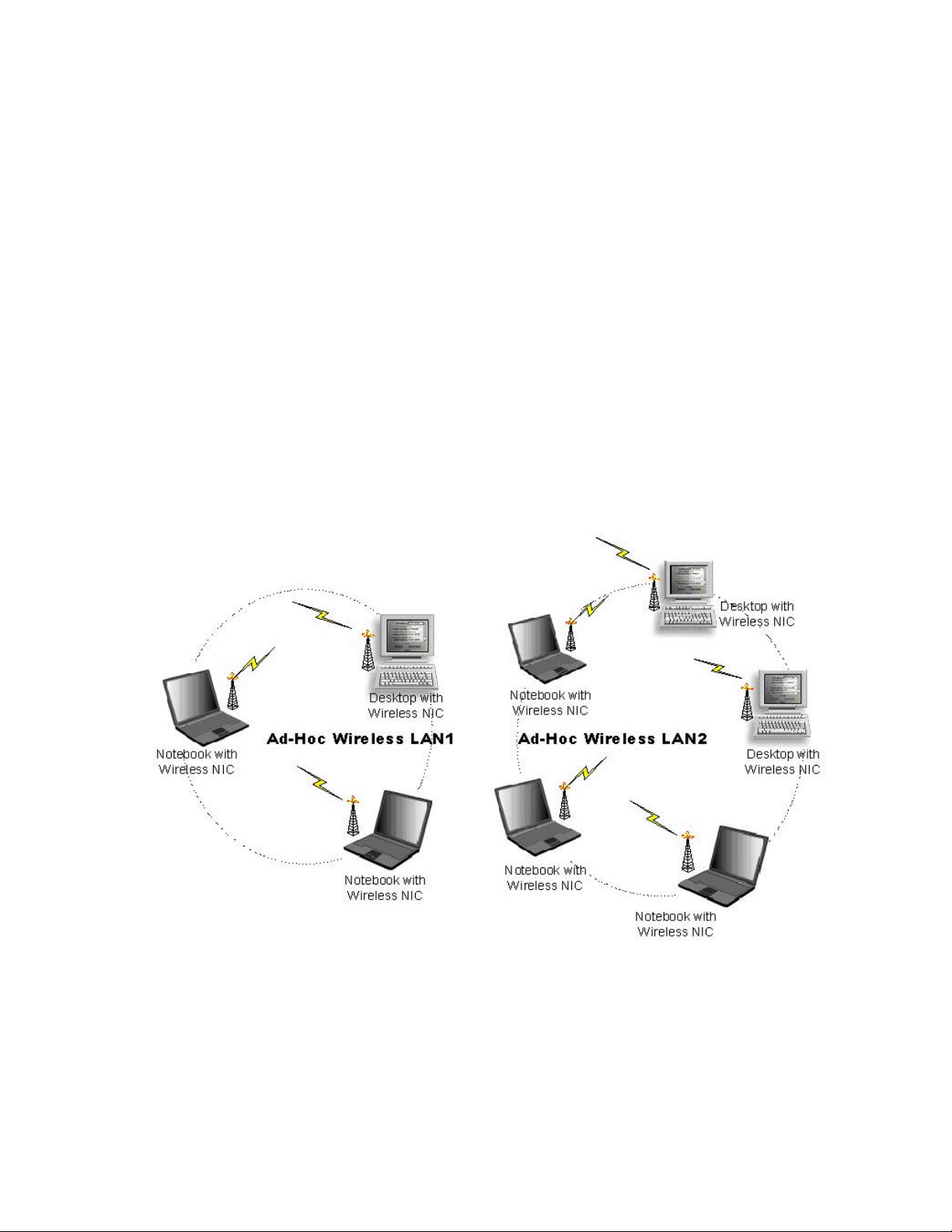
2.1 Ad -Hoc Topology
“Ad-Hoc” is the peer -to-peer mode of network operation without access point. An Ad-Hoc
wireless LAN is a group of computers, which equipped with the wireless adapters and
connected each together as an independent wireless LAN. Computers in a specific Ad -Hoc
wireless LAN must be configured at the same radio channel and SSID for establishing the
wireless connection. Ad-Hoc wireless LAN is ideally applicable at a departmental scale for a
branch or SOHO operation.
________________________________________________________________________
Page: 5
Page 6
__________________________________________________________________________________________________________________________________________
________________________________
WF-100 CompactFlash Wireless LAN Card User Manual
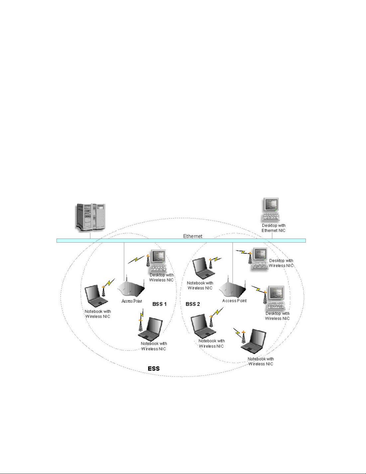
2.2 Infrastructure Topology
Infrastructure mode of network operation requires the presence of an access point at least. In
this mode, all wireless LAN client devices need to build the communication with the access
point first and then access to a wired LAN such as Ethernet. Therefore, an integrated wireless
and wired LAN is called an infrastructure configuration. A group of wireless LAN client users
and an access point construct a Basic Service Set (BSS). Each wireless LAN client device in
this BSS can talk to any device in the wired LAN infrastructure via the access point. In this
infrastructure configuration, wireless LAN systems will extend the accessibility to the wired
LAN. On the other hand, infrastructure mode also supports ro aming capability for mobile
wireless LAN users. More than one BSS can be configured as an Extended Service Set
(ESS). The continuous network allow s wireless LAN users to roam freely within an ESS. The
premise to build an ESS is that all wireless LAN client devices and access points within the
ESS must be configured with the same ESS ID.
________________________________________________________________________
Page: 6
Page 7
__________________________________________________________________________________________________________________________________________
________________________________
WF-100 CompactFlash Wireless LAN Card User Manual
3. Installation Procedure for Windows
3.1 Installation for Windows XP
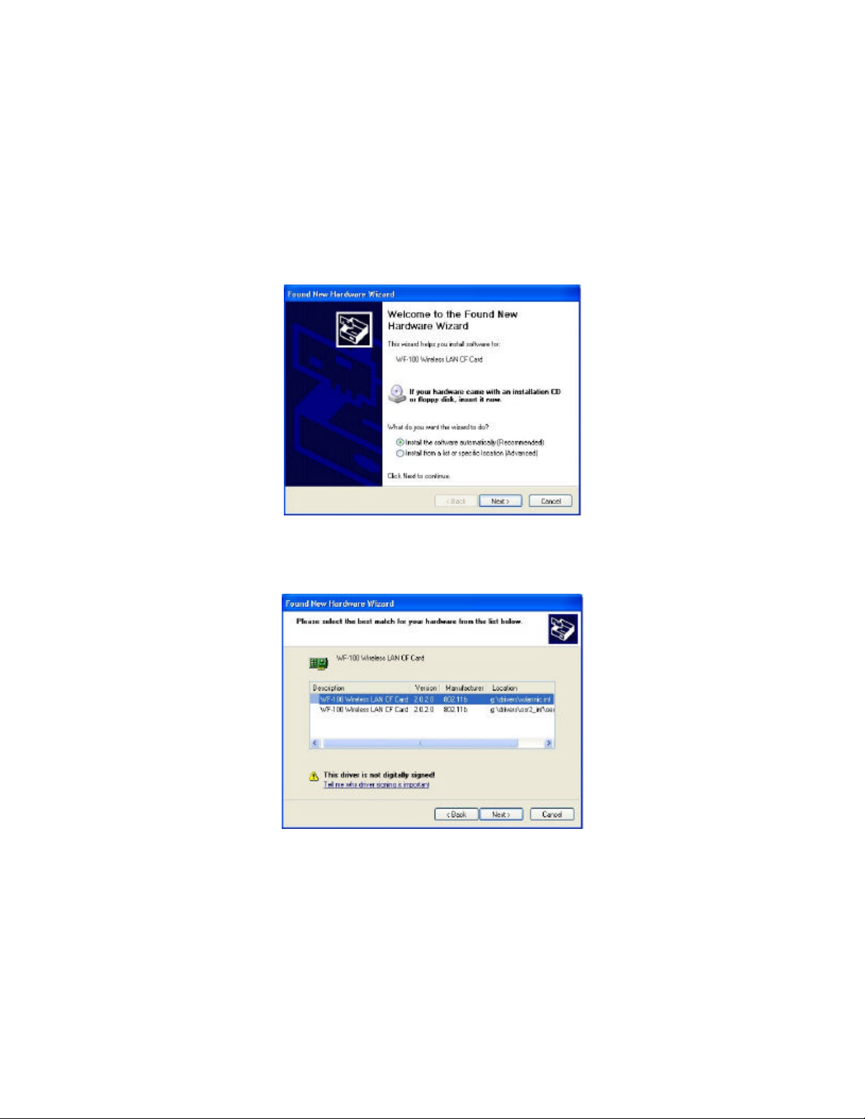
1. Insert the WF-100 CompactFlash card into a CompactFlash slot of a computer. Then the
system will automatically detect the new hardware and prompt you to start the installation
of the driver. Please put the device driver CD into the CD-ROM drive, and then click
button to continue.
Next
2. Select the driver file “wlannic.inf”. Click
button to continue.
Next
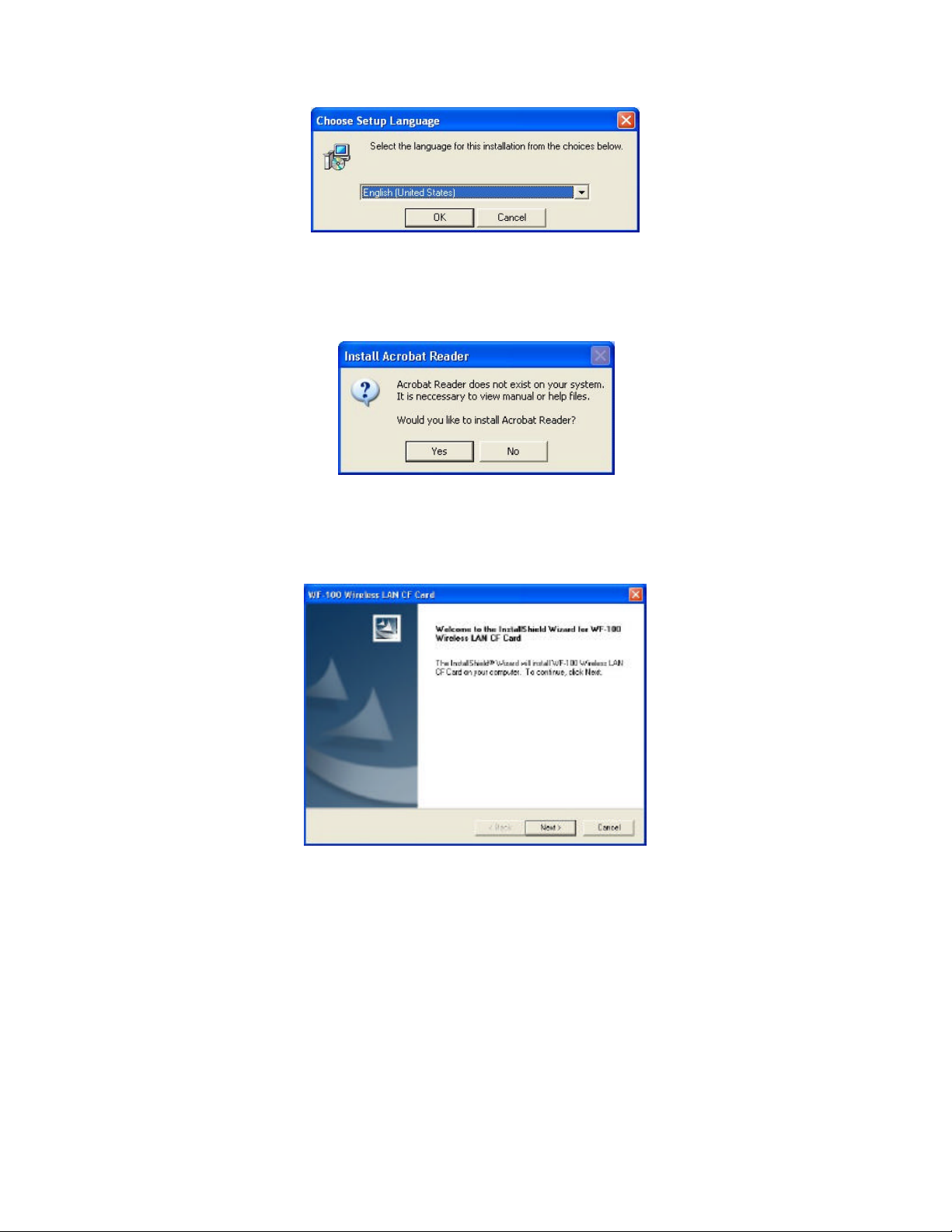
3. Now, it ’s time to install the software of this card. Please choose the language for the
following installation instructions.
________________________________________________________________________
Page: 7
Page 8
__________________________________________________________________________________________________________________________________________
________________________________
WF-100 CompactFlash Wireless LAN Card User Manual
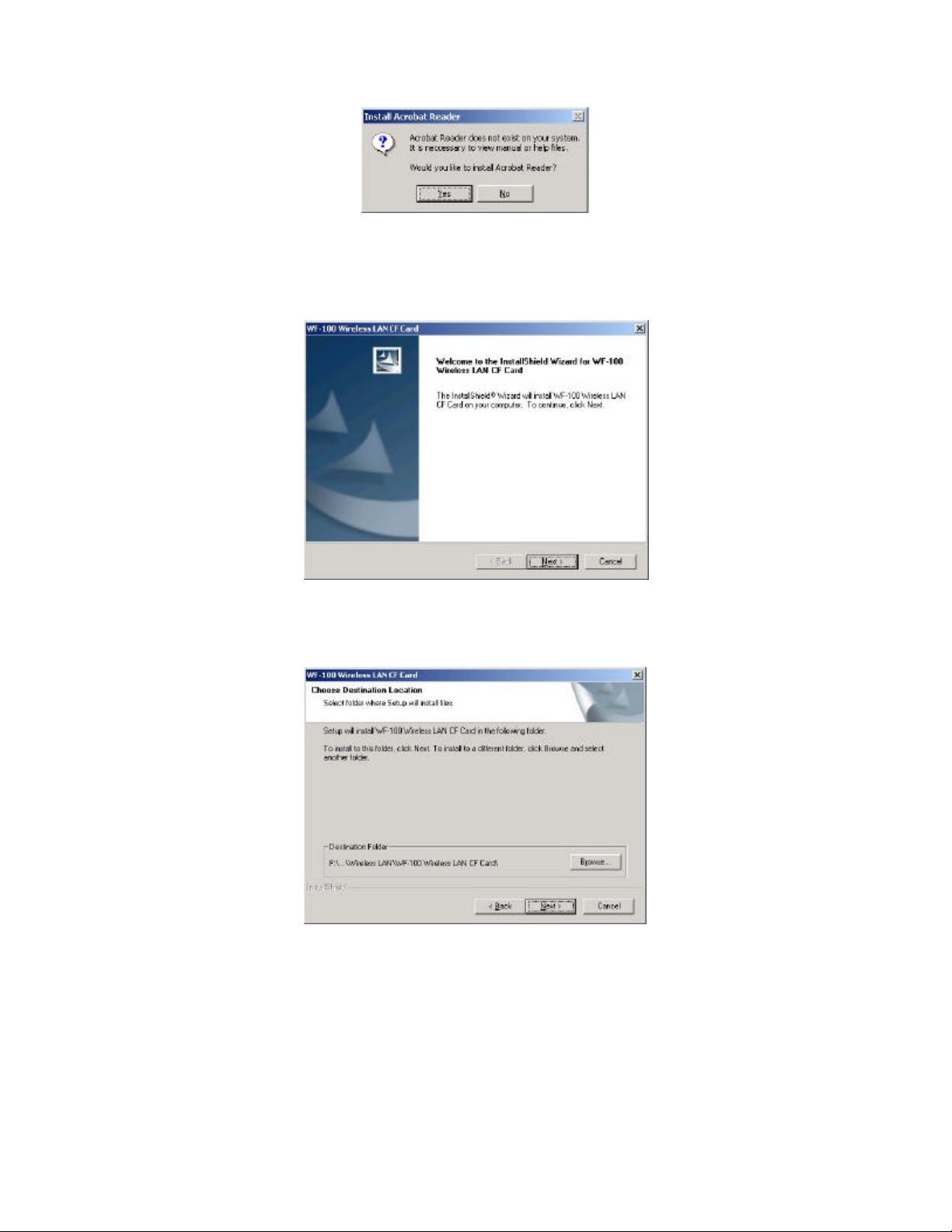
4. If there is no Acrobat Reader on the system, you may install it right away. With Acrobat
Reader you can read the user manual of the utility in PDF format.
5. A wizard begins to guide you through all the following installation steps. Click
Next
to
continue.
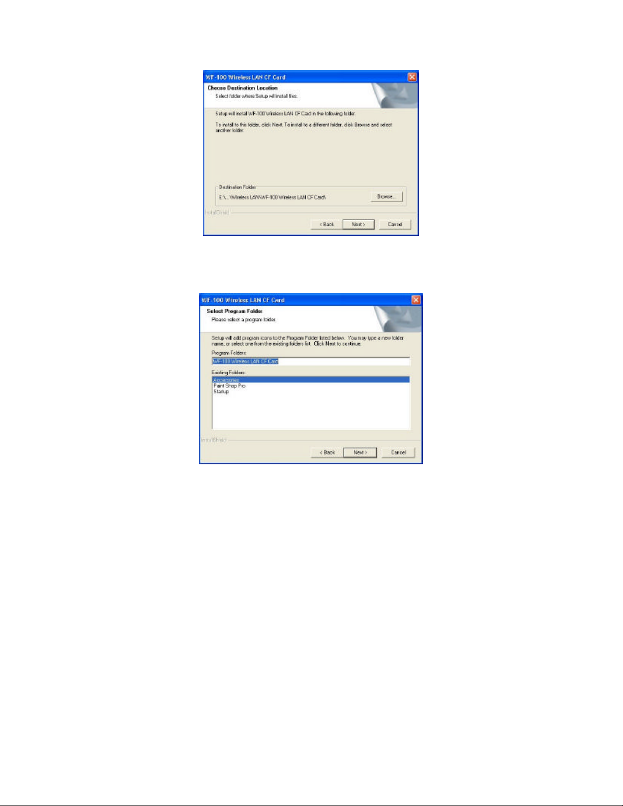
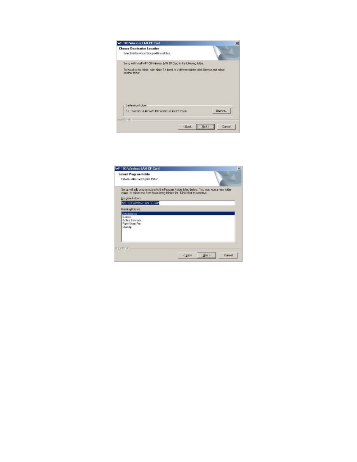
6. You may specify the destination location of the utility. Click
to continue.
Next
________________________________________________________________________
Page: 8
Page 9
__________________________________________________________________________________________________________________________________________
________________________________
WF-100 CompactFlash Wireless LAN Card User Manual
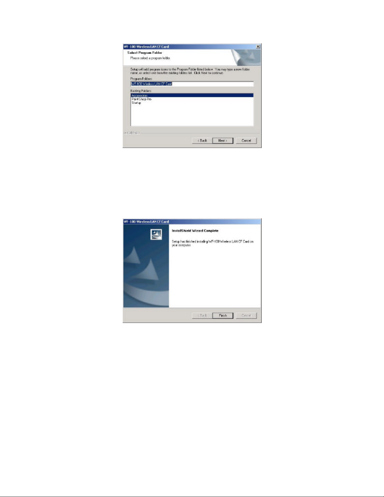
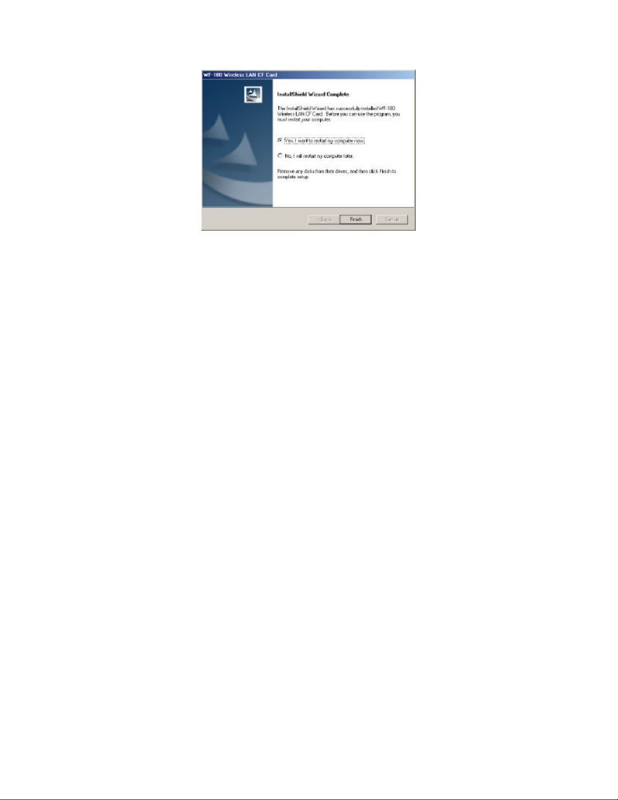
7. You may specify the program folder name. Click
to continue.
Next
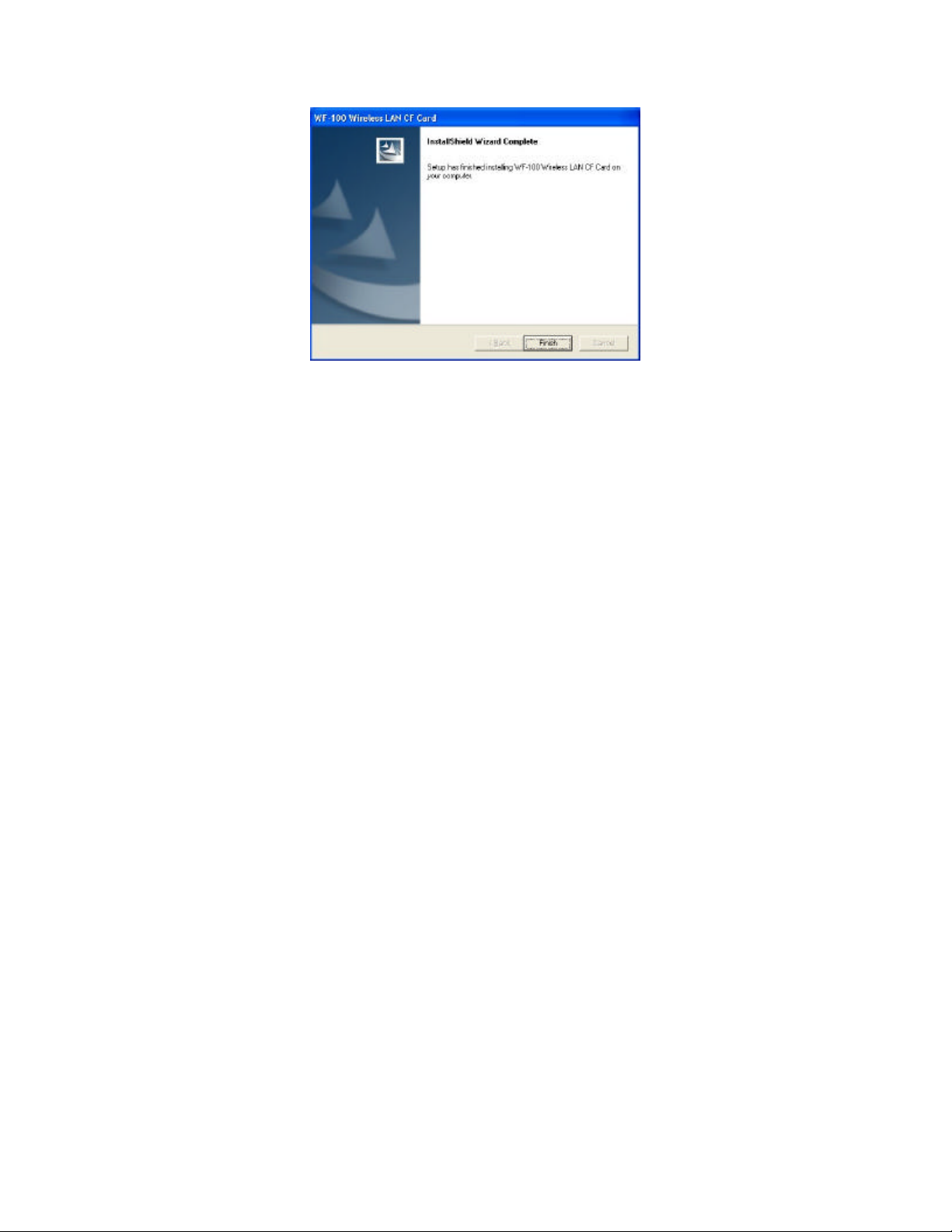
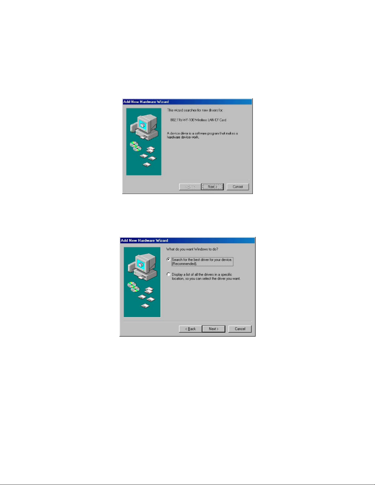
8. Then the wizard starts to perform setup operations including copying files, and this will
take a few seconds. When finished, click
to complete the software installation.
Finish
Sometimes the system will r equest you, if necessary, to restart your computer right away
to make the installation take . Just follow the on-screen instructions to finalize the
installation.
________________________________________________________________________
Page: 9
Page 10
__________________________________________________________________________________________________________________________________________
________________________________
WF-100 CompactFlash Wireless LAN Card User Manual
________________________________________________________________________
Page: 10
Page 11
__________________________________________________________________________________________________________________________________________
________________________________
WF-100 CompactFlash Wireless LAN Card User Manual
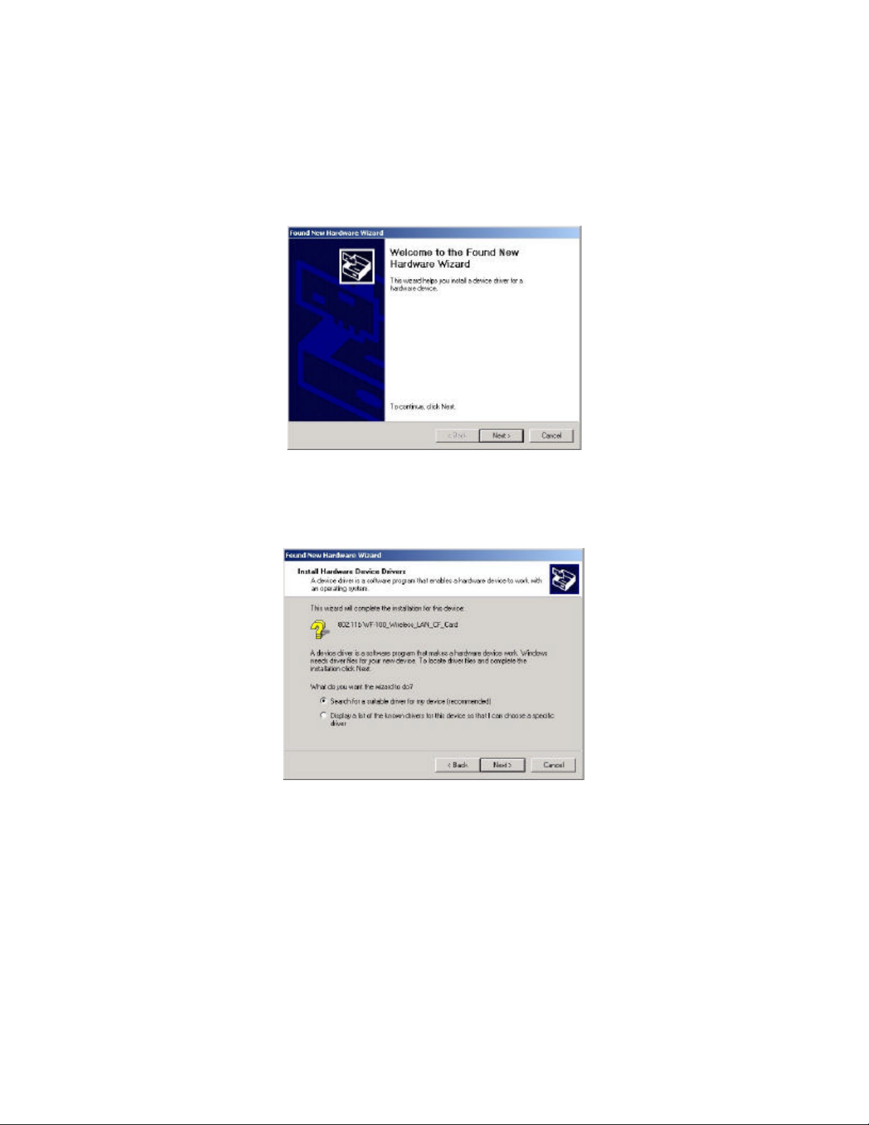
3.2 Installation for Windows 2000
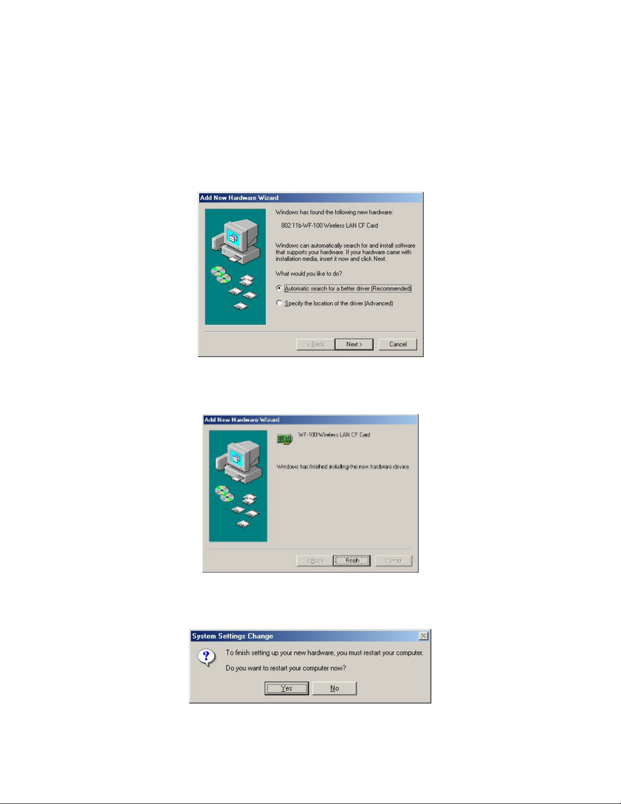
1. Insert the WF-100 CompactFlash card into a CompactFlash slot of a computer. Then the
system will automatically detect the new hardware and prompt you to start the installation
of the driver. Click
2. Select the option “Search for a suitable driver for my device (recommended)”, and click
button.
Next
to continue.
Next
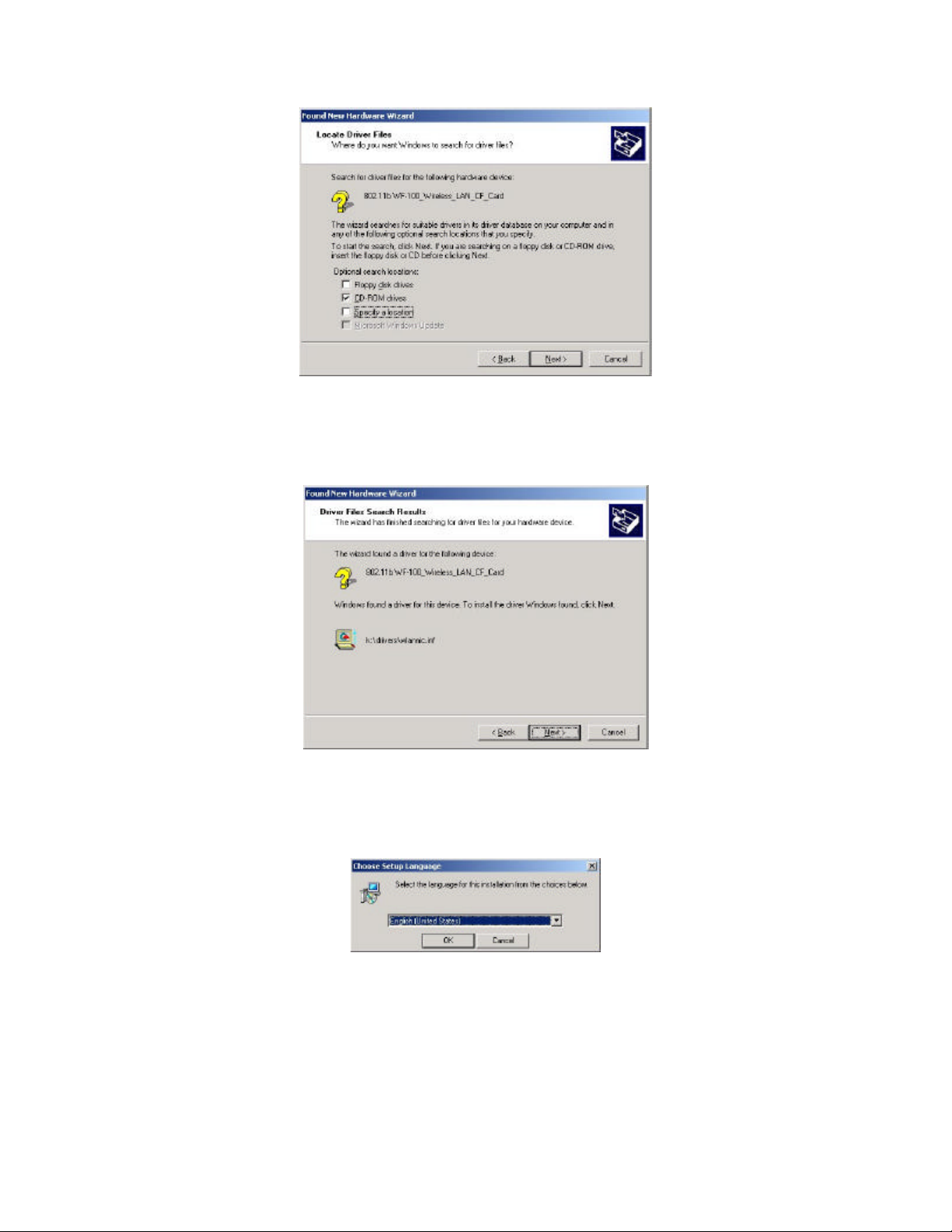
3. Check the “CD-ROM drives” only, and put the device driver CD into the CD-ROM
drive. Then click
Next
button.
________________________________________________________________________
Page: 11
Page 12
__________________________________________________________________________________________________________________________________________
________________________________
WF-100 CompactFlash Wireless LAN Card User Manual
4. Then the driver file “wlannic.inf” of the device will be found by the system. Click
Next
button to continue.
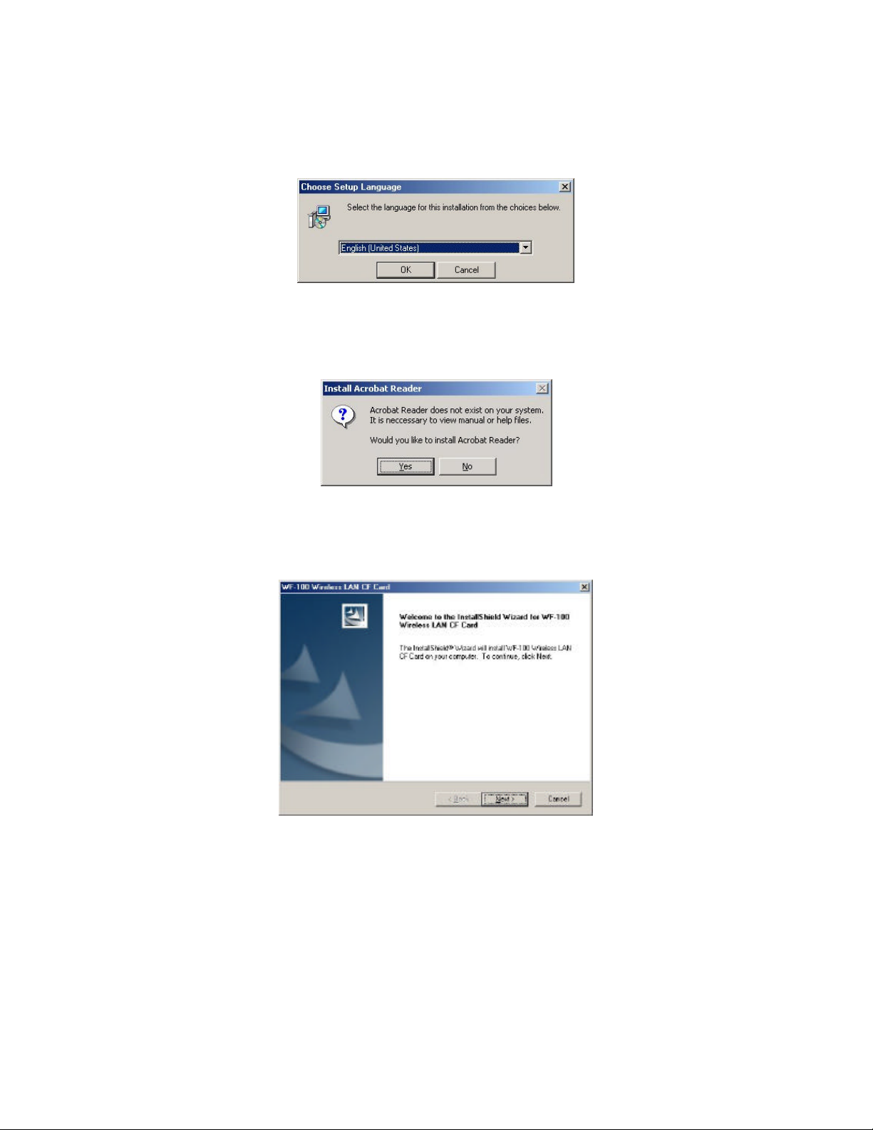
5. Now, it ’s time to install the software of this card. Please choose the language for the
following installation instructions.
6. If there is no Acrobat Reader on the system, you may install it right away. With Acrobat
Reader you can read the user manual of the utility in PDF format.
________________________________________________________________________
Page: 12
Page 13
__________________________________________________________________________________________________________________________________________
________________________________
WF-100 CompactFlash Wireless LAN Card User Manual
7. A wizard begins to guide you through all the following installation steps. Click
Next
to
continue.
8. You may specify the destination location of the utility. Click
to continue.
Next
9. You may specify the program folder name. Click
to continue.
Next
________________________________________________________________________
Page: 13
Page 14
__________________________________________________________________________________________________________________________________________
________________________________
WF-100 CompactFlash Wireless LAN Card User Manual
10. Then the wizard starts to perform setup operations including copying files, and it takes a
few seconds. When finished, click
to complete the software installation.
Finish
Sometimes the system will request you, if necessary, to restart your computer right away
to make the installation take effect. Just follow the on-screen instructions to finalize the
installation.
________________________________________________________________________
Page: 14
Page 15
__________________________________________________________________________________________________________________________________________
________________________________
WF-100 CompactFlash Wireless LAN Card User Manual
3.3 Installation for Windows Me
1. Insert the WF-100 CompactFlash card into a CompactFlash slot of a computer. And the
system will automatically detect the new hardware and prompt you to start the installation
of the driver. Then put the device driver CD into the CD-ROM drive. Similarly, the
system will automatically detect the driver files on the CD and perform the driver
installation.
2. The first phase of driver installation is finished. Please click
Finish
to continue.
3. Please restart your computer right away to get into the second phase of installation.
________________________________________________________________________
Page: 15
Page 16
__________________________________________________________________________________________________________________________________________
________________________________
WF-100 CompactFlash Wireless LAN Card User Manual
4. After restarting the system, you may choose the language for the following installation
instructions.
5. If there is no Acrobat Reader on the system, you may install it right away. With Acrobat
Reader you can read the user manual of the utility in PDF format.
6. A wizard begins to guide you through all the following installation steps. Click
to
Next
continue.
7. You may specify the destination location of the utility. Click
to continue.
Next
________________________________________________________________________
Page: 16
Page 17
__________________________________________________________________________________________________________________________________________
________________________________
WF-100 CompactFlash Wireless LAN Card User Manual
8. You may specify the program folder name. Click
to continue.
Next
9. Then the wizard starts to perform setup operations including copying files, and it takes a
few seconds. When finished, click
to complete the software installation.
Finish
Sometimes the system will request you, if necessary, to restart your computer right away
to make the installation take effect. Just follow the on-screen instructions to finalize the
installation.
________________________________________________________________________
Page: 17
Page 18
__________________________________________________________________________________________________________________________________________
________________________________
WF-100 CompactFlash Wireless LAN Card User Manual
________________________________________________________________________
Page: 18
Page 19
__________________________________________________________________________________________________________________________________________
________________________________
WF-100 CompactFlash Wireless LAN Card User Manual
3.4 Installation for Windows 98
1. Insert the WF-100 CompactFlash card into a CompactFlash slot of a computer. Then the
system will automatically detect the new hardware and prompt you to start the installation
of the driver. Click
to continue.
Next
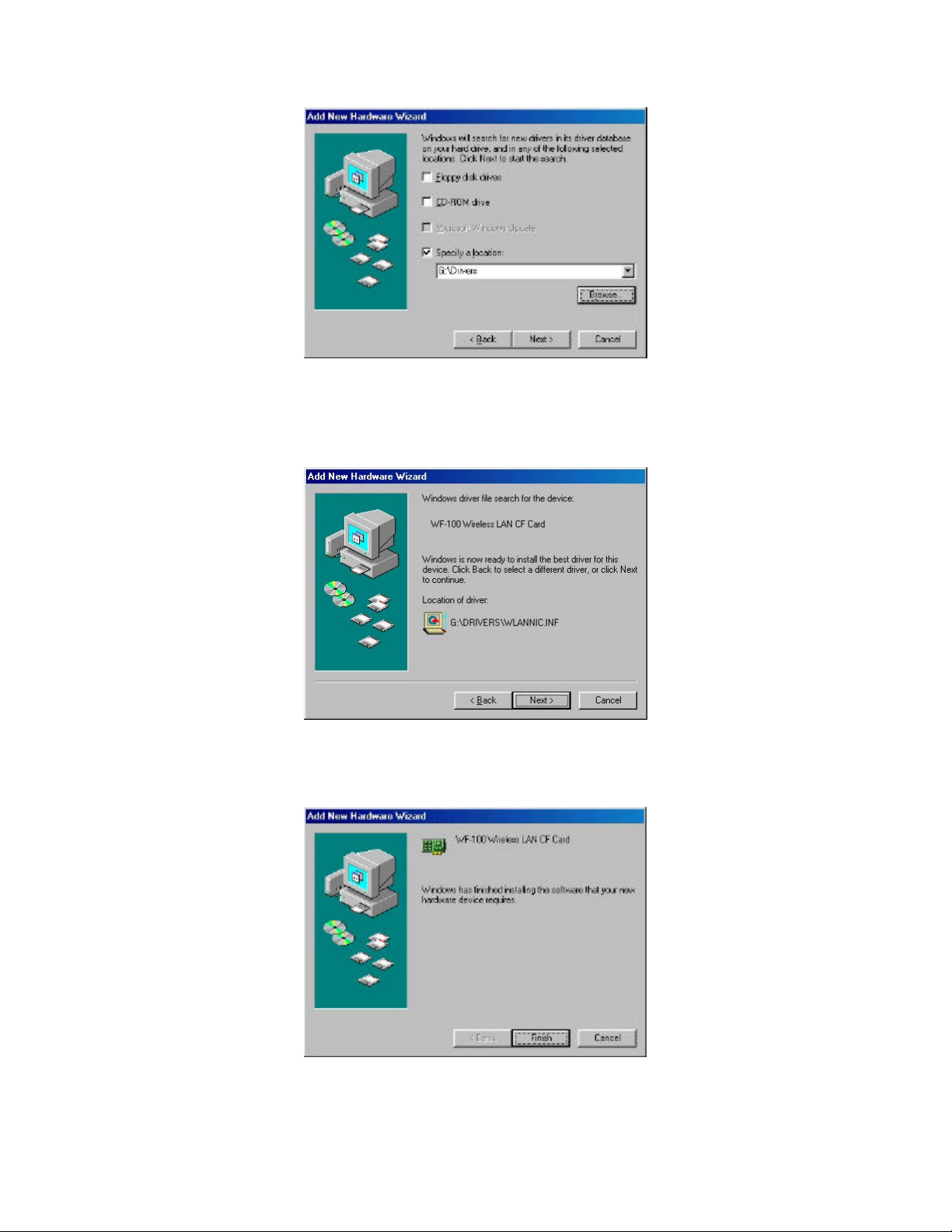
2. Select the option “Search for a suitable driver for my device (recommended)”, and click
button.
Next
3. Put the device driver CD into the CD-ROM and check the “Specify a location ”. Where
choose the folder “Drivers ” of the CD-ROM drive as the location.
________________________________________________________________________
Page: 19
Page 20
__________________________________________________________________________________________________________________________________________
________________________________
WF-100 CompactFlash Wireless LAN Card User Manual
4. Then the driver file “wlannic.inf” of the device will be found by the system. Click
Next
button to continue.
5. The first phase of driver installation is finished. Please click
Finish
to continue.
________________________________________________________________________
Page: 20
Page 21

__________________________________________________________________________________________________________________________________________
________________________________
WF-100 CompactFlash Wireless LAN Card User Manual
6. Please restart your computer right away to get into the second phase of installation.
7. After restarting the system, you may choose the language for the following installation
instructions.
8. If there is no Acrobat Reader on the system, you may install it right away. With Acrobat
Reader you can read the user manual of the utility in PDF format.
9. A wizard begins to guide you through all the following installation steps. Click
Next
continue.
________________________________________________________________________
Page: 21
to
Page 22

__________________________________________________________________________________________________________________________________________
________________________________
10. You may specify the destination location of the utility. Click
WF-100 CompactFlash Wireless LAN Card User Manual
to continue.
Next
11. You may specify the program folder name. Click
to continue.
Next
12. Then the wizard starts to perform setup operations including copying files, and it takes a
few seconds. When finished, click
to complete the software installation.
Finish
Sometimes the system will request you, if necessary, to restart your computer right away
to make the installation take effect. Just follow the on-screen instructions to finalize the
installation.
________________________________________________________________________
Page: 22
Page 23

__________________________________________________________________________________________________________________________________________
________________________________
WF-100 CompactFlash Wireless LAN Card User Manual
________________________________________________________________________
Page: 23
Page 24

__________________________________________________________________________________________________________________________________________
________________________________
WF-100 CompactFlash Wireless LAN Card User Manual
3.4 Uninstallation
WF-100
program. The uninstallation program conforms the standard Windows uninstallation
look-and-feel. Users can choose to run
Start menu to uninstall the software of
program will then remove the driver and utility from the system completely.
utility utilizes InstallShield uninstall ation mechanism to provide users an uninstallation
Remove Wireless LAN Dri ver
WF-100 Wireless LAN PC Card
from the Windows
. The uninstallation
As an alternative, users may also choose to uninstall the WF-100 software by running
Add/Remove Programs
in the
Control Panel
.
________________________________________________________________________
Page: 24
Page 25

__________________________________________________________________________________________________________________________________________
________________________________
WF-100 CompactFlash Wireless LAN Card User Manual
4. Installation Procedure for Pocket PC
4.1 Installation for Pocket PC
1. Insert the WF-100 CompactFlash card into the CompactFlash slot of your Pocket PC.
2. Connect the Pocket PC to your host computer and check that the state of
has become
Connected
.
ActiveSync
3. Put the device driver CD into the CD-ROM drive, and then start to install the software
from host computer to Pocket PC via
ActiveSync
. Please choose the language for the
following installation instructions.
4. A wizard begins to guide you through all the following installation steps. Click
Next
to
continue.
________________________________________________________________________
Page: 25
Page 26

__________________________________________________________________________________________________________________________________________
________________________________
WF-100 CompactFlash Wireless LAN Card User Manual
5. Click
to install to the default directory.
Yes
6. Then the wizard starts to perform software setup operations including copying files, and it
takes a few seconds. When finished, the system will advise you of checking screen
message on Pocket PC. Just follow the message to reset your Pocket PC to make the
driver installation take effect.
7. Press
to finalize the installation.
Finish
________________________________________________________________________
Page: 26
Page 27

__________________________________________________________________________________________________________________________________________
________________________________
WF-100 CompactFlash Wireless LAN Card User Manual
________________________________________________________________________
Page: 27
Page 28

__________________________________________________________________________________________________________________________________________
________________________________
WF-100 CompactFlash Wireless LAN Card User Manual
4.2 Uninstallation
Users may use
Remove Programs
Remove Programs
tab of
the item
Settings
, then click the
802.11b Wireless LAN for WinCE
Remove Programs.
completely.
, you may select the
After that, the driver and utility will be removed from the system
in your Pocket PC to uninstall the driver. To run the
Settings
Remove Programs
and click
item from
icon. To uninstall the driver, just choose
Remove
menu, change to
Start
button on the screen of
System
________________________________________________________________________
Page: 28
Page 29

closer to
One level
with a red
__________________________________________________________________________________________________________________________________________
________________________________
WF-100 CompactFlash Wireless LAN Card User Manual
5. Wireless Client Management Utility For Windows
Wireless Client Management Utility (
users to easily manage the wireless card.
l Status Icon
l Status Tab
l Profile Tab
l Encryption Tab
A taskbar icon immediately shows the current connection status.
Show wireless information of the current connection.
Allow users configure different wireless settings for each profile.
provide interface to add WEP keys to prevent unauthorized users
from accessing your wireless network.
l Survey Tab
Provide a site-survey tool to list all the active access points and
ad-hoc stations that are within the range of your computer
l Statistics Tab
l About Tab
Display statistical counters of data transmission and reception.
Display software/firmware versions and frequency doma in of the
card.
After installation,
may launch the utility window from
.
Icon
will automatically run and show
WCM
start menu, control panel
Detailed descriptions of features are provided in the following sections.
WCM
) provides the following window interfaces for
Status Icon
, or just double-clicking
on the taskbar. Users
Status
5.1 Status Icon
Status Icon
following.
IconIcon IndicationIndication DescriptionDescription ColorColor
indicates the current connection status of the station. It can be one of the
Excellent/Good Link Quality
Fair Link Quality
Poor Link Quality
Not Linked The signal is lost for the preferred connection. Empty
Data Frame Errors – Check
WEP Settings
The link quality of the current connection is
excellent/good.
The link quality of the current connection is
fair. Please move the station closer to the
Access Point
The link quality of the current connection is
poor. Please save your files if you are
transferring files and move the station
the Access Point.
The encryption is enabled but the key of the
station doesn’t match the key of the sender.
Or the encryption is disabled but what in the
sender is enabled. Please check WEP key
settings.
Light
green
Yellow
of Yellow
A key
“X”
________________________________________________________________________
Page: 29
Page 30

The wireless LAN card has no RF radio signal.
__________________________________________________________________________________________________________________________________________
________________________________
WF-100 CompactFlash Wireless LAN Card User Manual
Users may click
wireless radio , launch the utility window for the wireless settings, or remove this status icon
from the taskbar.
If users double-click
Radio Off
Status Icon
Status Icon
Please enable RF radio using Wireless Client
Management Utility.
A red “X”
to pop up a selection menu, where users can turn on/off the
, the utility window will be launched.
________________________________________________________________________
Page: 30
Page 31

__________________________________________________________________________________________________________________________________________
________________________________
WF-100 CompactFlash Wireless LAN Card User Manual
5.2 Status Tab
The
current profile. Figure 1 shows the screen layout of the
tab of the utility window provides information of the wireless connection on the
Status
Status tab.
Profile Name
Show the engaged profile name . Users may change the profile for different connection.
SSID
Short for
Service Set Identifier,
wireless network.
State
Display the current link state of the station.
l MAC address of the access point
address (BSSID) of the access point in
l Scanning
-- the station is searching for available access point of specified SSID in
Access Point Mode
l Associated
– the station is currently communicating with another station in the
Peer-to-Peer Mode
l Not Associated
SSID in the
– the station cannot detect any available station with the specified
Peer-to-Peer Mode
a unique identifier referred to as a Network Name of a
— if connected, this column displays the MAC
Access Point Mode
.
. If disconnected, this column is always in this state.
.
.
________________________________________________________________________
Page: 31
Page 32

__________________________________________________________________________________________________________________________________________
________________________________
WF-100 CompactFlash Wireless LAN Card User Manual
Mode
l Access point
– This mode of operation requires the presence of an access point. All
communication is done via the access point, which relays packets to other wireless
clients in the BSS as well as to nodes on a wired network such as Ethernet.
l Peer-to-Peer
– This is the peer-to-peer mode of operation. All communication is
done from client to client without using of an access point.
Current Tx Rate
Display the transmission rate of the current communication.
Current Channel
Display the channel of the current wireless connection. The communication channel ranges
from
1 to 11 (US/FCC, Canada/RSS)
,
1 to 13(Europe/ETSI) or 1 to 14(Japan/TELEC)
Power Saving Mode
Indicate the power saving mode is being enabled or disabled. Power saving mode can reduce
the power usage by temporarily disconnecting wireless connections when the connection is
idle.
RTS Threshold
Indicate RTS threshold status, which is set either
.
3000
disabled
or as the value ranging from
0 to
Frag . Threshold
Indicate fragmentation threshold status, which is either
256 to 2346
.
disabled
or as the value ranging from
Encryption
Indicate the state of WEP. If enabled, it indicates the status of 64 bits or 128 bits.
Throughput
Contain two fields displaying the instantaneous wireless receiving (Rx) and transmitting (Tx)
throughput values in bytes per second. These numbers are updated every second.
Link Status indication Figure
A series of figures indicate the current signal level, network mode, and WEP state. All figures
are described below.
Access Point / WEP disabled
The station receives excellent signals.
The WEP is disabled.
________________________________________________________________________
Page: 32
Page 33

the decryption key
__________________________________________________________________________________________________________________________________________
________________________________
WF-100 CompactFlash Wireless LAN Card User Manual
The station receives good signals.
The WEP is disabled.
The station receives fair signals.
The WEP is disabled..
The station receives a little bit weak signals.
The WEP is disabled.
The station only receives a little feeble
signal.
The WEP is disabled.
The station cannot receive any AP ’s signal.
The WEP is disabled.
Access Point / WEP enabled / WEP matched
The station receives excellent signals.
The WEP is enabled and
matches the key of the AP.
The station receives good signals.
The WEP is enabled and the decryption key
matches the key of the AP.
The station receives rather fair signals.
The WEP is enabled and the decryption key
matches the key of the AP.
The station receives a little bit weak signals.
The WEP is enabled and the decryption key
matches the key of the AP.
The station only receives a little feeble
signal.
The WEP is enabled and the decryption key
matches the key of the AP.
________________________________________________________________________
Page: 33
Page 34

__________________________________________________________________________________________________________________________________________
t match the key of the AP. Or the
AP is
t match the key of the AP. Or the
is disabled but what in the AP is
t match the key of the AP. Or the
is disabled but what in the AP is
t match the key of the AP. Or the
the AP is
The WEP is enabled but the
t match the key of the
is disabled but what in the
________________________________
Access Point / WEP enabled / WEP mismatched
WF-100 CompactFlash Wireless LAN Card User Manual
The station receives excellent signals.
The WEP is enabled but the decryption key
doesn’
WEP is disabled but what in the
enabled.
The station receives good signals.
The WEP is enabled but the decryption key
doesn’
WEP
enabled.
The station receives fair signals.
The WEP is enabled but the decryption key
doesn’
WEP
enabled.
The station receives a little bit weak signals.
The WEP is enabled but the decryption key
doesn’
WEP is disabled but what in
enabled.
The station only receives a little feeble
signal.
decryption key doesn’
AP. Or the WEP
AP is enabled.
The station cannot receive any AP ’s signal.
The WEP is enabled.
Peer-to-Peer / WEP disabled
The station receives excellent signals.
The WEP is disabled.
The station receives good signals.
The WEP is disabled.
The station receives fair signals.
The WEP is disabled.
The station receives a little bit weak signals.
The WEP is disabled.
________________________________________________________________________
Page: 34
Page 35

t match the key of the sender. Or the
der is
t match the key of the sender. Or the
is disabled but what in the sender is
__________________________________________________________________________________________________________________________________________
________________________________
WF-100 CompactFlash Wireless LAN Card User Manual
The station only receives a little feeble
signal.
The WEP is disabled.
The station cannot receive any signal.
The WEP is disabled.
Peer-to-Peer / WEP enabled / WEP matched
The station receives excellent signals.
The WEP is enabled and the decryption key
matches the key of the sender.
The station receives good signals.
The WEP is enabled and the decryption key
matches the key of the sender.
Peer-to-Peer / WEP enabled / WEP mismatched
The station receives fair signals.
The WEP is enabled and the decryption key
matches the key of the sender.
The station receives a little bit weak signals.
The WEP is enabled and the decryption key
matches the key of the sender.
The station only receives a little feeble
signal.
The WEP is enabled and the decryption key
matches the key of the sender.
The station receives excellent signals.
The WEP is enabled but the decryption key
doesn’
WEP is disabled but what in the sen
enabled.
The station receives good signals.
The WEP is enabled but the decryption key
doesn’
WEP
enabled.
________________________________________________________________________
Page: 35
Page 36

__________________________________________________________________________________________________________________________________________
t match the key of the sender. Or the
is disabled but what in the sender is
t match the key of the sender. Or the
sabled but what in the sender is
The WEP is enabled but the
t match the key of the
is disabled but what in
________________________________
WF-100 CompactFlash Wireless LAN Card User Manual
The station receives fair signals.
The WEP is enabled but the decryption key
doesn’
WEP
enabled.
The station receives a little bit weak signals.
The WEP is enabled but the decryption key
doesn’
WEP is di
enabled.
The station only receives a little feeble
signal.
decryption key doesn’
sender. Or the WEP
the sender is enabled.
The station cannot receive any signal.
The WEP is enabled.
________________________________________________________________________
Page: 36
Page 37

__________________________________________________________________________________________________________________________________________
________________________________
WF-100 CompactFlash Wireless LAN Card User Manual
5.3 Profile Tab
The
Profile
Totally up to 9 different profiles can be added in the system. A ll settings in the
alterable. After filling the profile name and other settings, users may click
to save the profile. Figure 2 shows the screen layout of the profile tab .
tab provides users to configure a profile of wireless connection in preference.
Profile
Apply
tab are
or OK button
Profile Name
Give a name to the profile.
SSID
Short for
Service Set Identifier
, a 32-character unique identifier referred to as a Network
Name of a wireless network. The default value is “ANY”. This allows your wireless client to
automatically associate to any access point within the range of the station.
Mode
Select the wireless networ k mode. It can be
default setting i s
Access Point
.
Access Point
or
Peer-to-Peer
Mode. The
Transmission Rate
The transmission rate tells the speed of the transmission. It can be
2Mbps, 5.5Mbps, 11Mbps, or Fully Automatic
. It is
1Mbps, 2Mbps, Auto 1 or
Full y Automatic
by default.
________________________________________________________________________
Page: 37
Page 38

__________________________________________________________________________________________________________________________________________
________________________________
WF-100 CompactFlash Wireless LAN Card User Manual
Channel
Select the transmission channel in
Peer-to-Peer
mode.
Power Saving Mode
Choice of the power sav ing. The power saving mode can reduce power usage by temporarily
disconnecting wireless connections when the connection is idle. The default setting is disabled.
RTS Threshold
Give the threshold of RTS. The RTS mechanism provides a solution to prevent data collisions.
But enabling RTS Threshold may cause redundant network overhead that could negatively
affect the throughput performance . When setting
Enable
, users may adjust the value from 0 to
3000.
Frag . Threshold
Give the threshold of Fragmentation. The fragmentation mechanism is for improving the
efficiency when high traffic flows along in the wireless network. If the device often transmits
large files in wireless network, users can enable the Fragmentation Threshold and the
mechanism will split the packet to send. When setting
Enable
, users may adjust the value from
256 to 2346.
Restore Defaults
Press this button to restore all settings by default into the current profile.
________________________________________________________________________
Page: 38
Page 39

__________________________________________________________________________________________________________________________________________
________________________________
WF-100 CompactFlash Wireless LAN Card User Manual
5.4 Encryption Tab
The
Encryption
using
WEP (Wired Equivalent Privacy)
stations from accessing data transmitted over the network, WEP can support high secure data
encryption. WEP encrypts each frame transmitted through the radio by using one of the
entered from this panel. When an encrypted frame is received, it will only be accepted if it
decrypts correctly. This will only happen if the receiver has the same
transmitter. The
tab equip s an additional measure of security on your wireless network by
encryption. To prevent unauthorized wireless
Keys
used by the
Encryption
WEP Key
tab contains some settings as below.
Encryption (WEP security)
It allows you to select
Disabled, 64 bit
or
128 bit
. When setting
64 bit
or
128 bit
, it means
WEP security is in operation.
WEP Key
You can choose
Create Keys Manually
encryption keys. It allows
four keys for 64-bit and 128-bit key
or
Create Keys with Passphrase
according to WEP function
to enter
select. The detailed descriptions will be shown as below for these two kinds of methods:
Create Key Manually
For 64-bits encryption:
- 5 alphanumeric characters in the range of “a-z”, “A-Z ” and “0-9”. (e.g. MyKey)
________________________________________________________________________
Page: 39
Page 40

__________________________________________________________________________________________________________________________________________
________________________________
WF-100 CompactFlash Wireless LAN Card User Manual
- 10 digit hexadecimal values in the range of “A-F” and “0-9”. (e.g. 11AA22BB33).
For 128-bits encryption:
- 13 alphanumeric characters in the range of “a-z”, “A-Z” and “0-9”. (e.g.
WEPencryption).
- 26 digit hexadecimal values in the range of “A-F” and “0-9”. (e.g.
11AA22BB33123456789ABCDEFF)
Create Keys with Passphrase
A passphrase is a string of ASCII characters, which will be automatically converted into four
different hexadecimal strings for four keys. This saves considerable time since the same keys
must be entered into each node on the wireless network.
Key1, Key2, Key3, Key4
These four columns can be used to manually enter the keys. These fields also display the keys
when they are generated by a passphrase.
Use WEP key
Indicate the key for encrypting sent packets.
________________________________________________________________________
Page: 40
Page 41

__________________________________________________________________________________________________________________________________________
________________________________
WF-100 CompactFlash Wireless LAN Card User Manual
5.5 Survey Tab
The
Survey
radio range of the station. For any discovered device , users may press
double click it to make the station immediately connect to. And the system will simultaneously
change the profile to “Default” and update the content of the
device’s settings. Users may also press
result anytime. The
tab support s a Site-Survey tool to discover all active wireless devices within the
button or
to match such
Survey
Rescan
button to scan again and update the survey
tab contains some columns as below.
Connect
profile tab
Number of Discoveries
Show th e total number of wireless LAN devices discovered by the current scan.
Indicate the discovered device to which the station is currently connecting.
Indicate the discovered devices to which the station is not currently connecting.
SSID
Short for
Service Set Identifier,
a unique identifier referred to as a Network Name of a
wireless network.
________________________________________________________________________
Page: 41
Page 42

__________________________________________________________________________________________________________________________________________
________________________________
WF-100 CompactFlash Wireless LAN Card User Manual
BSSID
Short for
Basic Service Set Identifier
, during the infrastructure mode, it represents the
MAC address of the access point.
Mode
Show the discovered device is an access point (AP) or a peer-to-peer (p2p) station.
WEP
Show whether the discovered device is WEP enabled.
Signal Level
Display the signal strength level of the discovered device.
Channel
Display the current communication chann el used by the discovered device.
Connect
Users may press this button to make the station immediately connect to the selected device.
And the system will simultaneously change the profile to “Default” and update the content of
the
profile tab
to match suc h device’s settings.
Rescan
Press this button to scan again.
________________________________________________________________________
Page: 42
Page 43

__________________________________________________________________________________________________________________________________________
________________________________
WF-100 CompactFlash Wireless LAN Card User Manual
5.6 Statistics Tab
The
Statistics
network. Users can press
freeze the current showed counters, they can press
detailed
tab monitors the successful and failed transmission traffic of the wireless
button to restart the counter, or just want to temporarily
Reset
button to do that easily. The
Pause
Statistics
information contains some columns as below.
Bytes (Tx Counters)
The number of wireless sent bytes.
Fragments (Tx Counters)
The number of successfully delivered MPDUs of type Data or Management.
Unicast Packets (Tx Counters)
The number of wireless sent unicast packets.
Single Retries
The number of MSDUs successfully transmitted after one (and only one) retransmission.
Multiple Retries
The number of MSDUs successfully transmitted after more than one retransmission.
Retry Limit Exceed ed
________________________________________________________________________
Page: 43
Page 44

__________________________________________________________________________________________________________________________________________
________________________________
WF-100 CompactFlash Wireless LAN Card User Manual
The number shows the times of failed transmitted MSDU that caused by reaching the retry
limitation (7 for short frame and 4 for long frame) due to no acknowledgement or CTS
received.
Deferred Transmissions
The number of MSDUs that one or more transmission attempt(s) was deferred to avoid a
collision.
Bytes (Rx Counters)
The number of received bytes of wireless transmission.
Fragments (Rx Counters)
The number of successfully received MPDUs of type Data or Management.
Unicast Packets (Rx Counters)
The number of received unicast packets of wireless transmission.
WEP Undercryptable
The number of received MPDUs, with the WEP subfield in the Frame Control field set to one,
that were discarded because either it should not have been encrypted, or due to the receiving
station not implementing the privacy option.
No Buffer Discarede
The discarded number of received MPDUs, which is because the lack of buffer space on the
NIC.
No Buffer Discarede
The discarded number of received MPDUs, which is because the lack of buffer space on the
NIC.
Time Elapse
The timer for the accumulation of these counters
Pause/Continue
Press
Continue
button to freeze the display of these counters’ accumulation and timer. Press
Pause
to resume normal display.
Reset
Reset all counters and timer.
________________________________________________________________________
Page: 44
Page 45

__________________________________________________________________________________________________________________________________________
________________________________
WF-100 CompactFlash Wireless LAN Card User Manual
5.7 About Tab
This tab shows the Frequency Domain, Wireless Client Management Utility versions, and
serial number and MAC address of the network interface card. Users need to use these
version numbers when reporting their problems to technique support.
________________________________________________________________________
Page: 45
Page 46

closer to
One level
on is disabled but what in the sender is
with a red
__________________________________________________________________________________________________________________________________________
________________________________
WF-100 CompactFlash Wireless LAN Card User Manual
6. Wireless Client Management Utility for Pocket PC
Wireless Client Management Utility (
users to easily manage the wireless card.
l Status Icon
l Status Tab
l Profile Tab
l Encryption Tab
A taskbar icon immediately shows the current connection status.
Show wireless information of the current connection.
Allow users configure different wireless settings for each profile.
provide interface to add WEP keys to prevent unauthorized users
from accessing your wireless network.
l Survey Tab
Provide a site-survey tool to list all the active access points and
ad-hoc stations that are within the range of your computer
l Statistics Tab
l About Tab
Display statistical counters of data transmission and reception.
Display software/firmware versions and frequency domain of the
card.
After installation,
will automatically run and show
WCM
may launch the utility window from
double-clicking
Status Icon
.
Detailed descriptions of features are provided in the following sections.
) provides the following window interfaces for
WCM
Status Icon
on the taskbar. Users
start menu, System tab in Settings
, or just
6.1 Status Icon
Status Icon
following.
IconIcon IndicationIndication DescriptionDescription ColorColor
indicates the current connection status of the station. It can be one of the
Excellent/Good Link Quality
Fair Link Quality
Poor Link Quality
Not Linked The signal is lost for the preferred connection. Empty
Data Frame Errors – Check
WEP Settings
The link quality of the current connection is
excellent/good.
The link quality of the current connection is
fair. Please move the station closer to the
Access Point
The link quality of the current connection is
poor. Please save your files if you are
transferring files and move the station
the Access Point.
The encryption is enabled but the key of the
station doesn’t match the key of the sender.
Please check WEP key settings. Or the
encrypti
enabled. Please check WEP key settings.
Light
green
Yellow
of Yellow
A key
“X”
________________________________________________________________________
Page: 46
Page 47

The wireless LAN card has no RF radio signal.
Please enable RF radio using Wireless Client
__________________________________________________________________________________________________________________________________________
________________________________
WF-100 CompactFlash Wireless LAN Card User Manual
Users may click
wireless radio , launch the utility window for the wireless settings, or remove this status icon
from the taskbar .
The utility window will also be launched if users double-click the
Radio Off
Status Icon
A red “X”
Management Utility.
to pop up a selection menu, where users can turn on/off the
Status Icon
.
________________________________________________________________________
Page: 47
Page 48

__________________________________________________________________________________________________________________________________________
________________________________
WF-100 CompactFlash Wireless LAN Card User Manual
6.2 Status Tab
The
current profile. Figure 1 shows the screen layout of the
tab of the utility window provides information of the wireless connection on the
Status
Status tab.
Profile Name
Show the engaged profile name . Users may change the profile for different connection.
SSID
Short for
Service Set Identifier,
wireless network.
Mode
l Access point
– This mode of operation requires the presence of an access point. All
communication is done via the access point, which relays packets to other wireless
clients in the BSS as well as to nodes on a wired network such as Ethernet.
l Peer-to-Peer
– This is the peer-to-peer mode of operation. All communication is
done from client to client without using of an access point.
State
Display the current link state of the station.
l MAC address of the access point
address (BSSID) of the access point in
l Scann ing
-- the station is searching for available access point of specified SSID in
Access Point Mode
l Associated
– the station is currently communicating with another station in the
Peer-to-Peer Mode
a unique identifier referred to as a Network Name of a
— if connected, this column displays the MAC
Access Point Mode
.
. If disconnected, this column is always in this state.
.
________________________________________________________________________
Page: 48
Page 49

matches
matches
__________________________________________________________________________________________________________________________________________
________________________________
l Not Associated
SSID in the
– the station cannot detect any available station with the specified
Peer-to-Peer Mode
WF-100 CompactFlash Wireless LAN Card User Manual
.
Current Tx Rate
Display the transmission rate of the current communication.
Current Channel
Display the channel of the current wireless connection. The communication channel ranges
from
1 to 11 (US/FCC, Canada/RSS)
,
1 to 13(Europe/ETSI) or 1 to 14(Japan/TELEC)
Power Sav e
Indicate the power saving mode is being enabled or disabled. Power saving mode can reduce
the power usage by temporarily disconnecting wireless connections when the connection is
idle.
Throughput
Contain two fields displaying the instantaneous wireless receiving (Rx) and transmitting (Tx)
throughput values in bytes per second. These numbers are updated every second.
Signal Level
A series of figures indicate the current signal level and WEP state. All figures are described
below.
WEP disabled
The station receives excellent signals.
The WEP is disabled.
The station receives good signals.
The WEP is disabled.
The station receives fair signals.
The WEP is disabled.
The station receives a little bit weak signals.
The WEP is disabled.
The station only receives a little feeble signal.
The WEP is disabled.
The station cannot receive any signal.
The WEP is disabled.
WEP enabled / WEP matched
The station receives excellent signals.
The WEP is enabled and the decryption key
the key of the sender.
The station receives good signals.
The WEP is enabled and the decryption key
the key of the sender.
________________________________________________________________________
Page: 49
Page 50

matches
matches
matches
t
is disabled
t
is disabled
t
is disabled
t
is disabled
t
is disabled
__________________________________________________________________________________________________________________________________________
________________________________
The station receives fair signals.
The WEP is enabled and the decryption key
the key of the sender.
The station receives a little bit weak signals.
The WEP is enabled and the decryption key
the key of the sender.
The station only receives a little feeble signal.
The WEP is enabled and the decryption key
the key of the sender.
WF-100 CompactFlash Wireless LAN Card User Manual
WEP enabled / WEP mismatched
The station receives excellent signals.
The WEP is enabled but the decryption key doesn’
match the key of the sender. Or the WEP
but what in the sender is enabled.
The station receives good signals.
The WEP is enabled but the decryption key doesn’
match the key of the sender. Or the WEP
but what in the sender is enabled..
The station receives fair signals.
The WEP is enabled but the decryption key doesn’
match the key of the sender. Or the WEP
but what in the sender is enabled.
The station receives a little bit weak signals.
The WEP is enabled but the decryption key doesn’
match the key of the sender. Or the WEP
but what in the sender is enabled.
The station only receives a little feeble signal.
The WEP is enabled but the decryption key doesn’
match the key of the sender. Or the WEP
but what in the sender is enabled.
The station cannot receive any signal.
The WEP is enabled.
________________________________________________________________________
Page: 50
Page 51

__________________________________________________________________________________________________________________________________________
________________________________
WF-100 CompactFlash Wireless LAN Card User Manual
6.3 Profile Tab
The
Profile
Totally up to 9 different profiles can be added in the system. A ll settings in the
alterable. After filling the profile name and other settings, users may click
to save the profile. Figure 2 shows the screen layout of the profile tab .
tab provides users to configure a profile of wireless connection in preference.
Profile
Apply
tab are
or OK button
Profile Name
Give a name to the profile.
SSID
Short for
Service Set Identifier
, a 32 -character unique identifier referred to as a Network
Name of a wireless network. The default value is “ANY”. This allows your wireless client to
automatically associate to any access point within the range of the station.
Mode
Select the wireless network mode. It can be
default setting i s
Access Point
.
Access Point
or
Peer-to-Peer
Mode. The
Tx Rate
The transmission rate tells the speed of the transmission. It can be
2Mbps, 5.5Mbps, 11Mbps, or Fully Automatic
. It is
1Mbps, 2Mbps, Auto 1 or
Fully Automatic
by default.
Channel
Select the transmission channel in
Peer-to-Peer
mode.
Power Sav e
________________________________________________________________________
Page: 51
Page 52

__________________________________________________________________________________________________________________________________________
________________________________
WF-100 CompactFlash Wireless LAN Card User Manual
Choice of the power sav ing. The power saving mode can reduce power usage by temporarily
disconnecting wireless connections when the connection is idle. The default setting is disabled.
Restore Defaults
Press this button to restore all settings by default into the current profile.
________________________________________________________________________
Page: 52
Page 53

__________________________________________________________________________________________________________________________________________
________________________________
WF-100 CompactFlash Wireless LAN Card User Manual
6.4 Encryption Tab
The
Encryption
using
WEP (Wired Equivalent Privacy)
stations from accessing data transmitted over the network, WEP can support high secure data
encryption. WEP encrypts each frame transmitted through the radio by using one of the
entered from this panel. When an encrypted frame is received, it will only be accepted if it
decrypts correctly. This will only happen if the receiver has the same
transmitter. The
tab equip s an additional measure of security on your wireless network by
encryption. To prevent unauthorized wireless
Keys
used by the
Encryption
WEP Key
tab co ntains some settings as below.
Encryption (WEP)
It allows you to select
Disabled, 64 bit
or
128 bit
. When setting
64 bit
or
128 bit
, it means
WEP security is in operation.
WEP Key
You can choose
Create Keys Manually
encryption keys. It allows
four keys for 64-bit and 128-bit key
or
Create Keys with Passphrase
according to WEP function
to enter
select. The detailed descriptions will be shown as below for these two kinds of methods:
Create Key Manually
For 64-bits encryption:
- 5 alphanumeric characters in the range of “a-z”, “A-Z ” and “0-9”. (e.g. MyKey)
- 10 digit hexadecimal values in the range of “A-F” and “0-9”. (e.g. 11AA22BB33).
For 128-bits encryption:
- 13 alphanumeric characters in the range of “a-z”, “A-Z” and “0-9”. (e.g.
________________________________________________________________________
Page: 53
Page 54

__________________________________________________________________________________________________________________________________________
________________________________
WF-100 CompactFlash Wireless LAN Card User Manual
WEPencryption).
- 26 digit hexadecimal values in the range of “A-F” and “0-9”. (e.g.
11AA22BB33123456789ABCDEFF)
Create Keys with Passphrase
A passphrase is a string of ASCII characters, which will be automatically converted into four
different hexadecimal strings for f our keys. This saves considerable time since the same keys
must be entered into each node on the wireless network.
Key1, Key2, Key3, Key4
These four columns can be used to manually enter the keys. These fields also display the keys
when they are generated by a passphrase.
Use WEP
Indicate the key for encrypting sent packets.
________________________________________________________________________
Page: 54
Page 55

__________________________________________________________________________________________________________________________________________
________________________________
WF-100 CompactFlash Wireless LAN Card User Manual
6.5 Survey Tab
The
Survey
radio range of the station. For any discovered device , users may press
double click it to make the station immediately connect to. And the system will simultaneously
change the profile to “Default” and update the content of the
device’s settings. Users may also press
result anytime. The
tab supports a Site -Survey tool to discover all active wireless devices within the
button or
to match such
Survey
Rescan
button to scan again and update the survey
tab contains some columns as below.
Connect
profile tab
Discoveries
Show th e total number of wireless LAN devices discovered by the current scan.
Indicate the discovered device to which the station is currently connecting.
Indicate the discovered devices to which the station is not currently connecting.
SSID
Short for
Service Set Identifier,
a unique identifier referred to as a Network Name of a
wireless network.
BSSID
Short for
Basic Service Set Identifier
, during the infrastructure mode, it represents the
MAC address of the access point.
________________________________________________________________________
Page: 55
Page 56

__________________________________________________________________________________________________________________________________________
________________________________
WF-100 CompactFlash Wireless LAN Card User Manual
Mode
Show the discovered device is an access point (AP) or a peer-to-peer (p2p) station.
WEP
Show whether the discovered device is WEP enabled.
Signal Level
Display the signal strength level of the discovered device.
Channel
Display the current communication channel used by the discovered device.
Connect
Users may press this button to make the station immediately connect to the selected device.
And the system will simultaneously change the profile to “Default” and update the content of
the
profile tab
to match such device’s settings.
Rescan
Press this button to scan again.
________________________________________________________________________
Page: 56
Page 57

__________________________________________________________________________________________________________________________________________
________________________________
WF-100 CompactFlash Wireless LAN Card User Manual
6.6 Statistics Tab
The
Statistics
network. Users can press
freeze the current showed counters, they can press
detailed
tab monitors the successful and failed transmission traffic of the wireless
button to restart the counter, or just want to temporarily
Reset
button to do that easily. The
Pause
Statistics
information contains some columns as below.
Bytes (Tx Counters)
The number of wireless sent transmission.
Fragments (Tx Counters)
The number of successfully delivered MPDUs of type Data or Management.
Unicast Packets (Tx Counters)
The number of wireless sent unicast packets.
Retry Exceeded
The number shows the times of failed transmitted MSDU that caused by reaching the retry
limitation (7 for short frame and 4 for long frame) due to no acknowledgement or CTS
received.
Deferred Tx
The number of MSDUs that one or more transmission attempt(s) was deferred to avoid a
collision.
Bytes (Rx Counters)
The number of received bytes of wireless transmission.
________________________________________________________________________
Page: 57
Page 58

__________________________________________________________________________________________________________________________________________
________________________________
WF-100 CompactFlash Wireless LAN Card User Manual
Fragments (Rx Counters)
The number of successfully received MPDUs of type Data or Management.
Unicast Packets (Rx Counters)
The number of received unicast packets of wireless transmission.
WEP Undercryptable
The number of received MPDUs, with the WEP subfield in the Frame Control field set to one,
that were discarded because either it should not have been encrypted, or due to the receiving
station not implementing the privacy option.
No Buffer Discarded
The discarded number of received MPDUs, which is because the lack of buffer space on the
NIC.
Time Elapse
The timer for the accumulation of these counters
Pause/Continue
Press
Continue
butto n to freeze the display of these counters’ accumulation and timer. Press
Pause
to resume normal display.
Reset
Reset all counters and timer.
IP Address
Display the current IP Address.
________________________________________________________________________
Page: 58
Page 59

__________________________________________________________________________________________________________________________________________
________________________________
WF-100 CompactFlash Wireless LAN Card User Manual
6.7 About Tab
This tab shows the Frequency Domain, Wireless Client Management Utility versions, and
serial number and MAC address of the network interface card. Users need to use these
version numbers when reporting their problems to technique support.
________________________________________________________________________
Page: 59
Page 60

__________________________________________________________________________________________________________________________________________
________________________________
WF-100 CompactFlash Wireless LAN Card User Manual
7. Hardware Technical Specification
Standard Compliance
IEEE 802.11b standard and WECA interoperability certified FCC part 15sec.15.
247/USA
CE/ETSI 300.328300.826/Eurpoe
TELEC/Japan
Electrical Specification
Parameter name Value Remark
Supply voltage range 3.0V~3.6V DC Bus powered
Average current: 290 mA typical 2% transmit, 98% receive
without power saving mode
AVERAGE CURRENT: 75 mA typical 2% transmit, 8% receive
90% standby with power saving
mode
Continuous transmit mode 300 mA max
Continuous receive mode: 290 mA max
Standby mode: 51 mA max with power saving mode
Form Factor
Comply with CompactFlash Type II Form Factor.
Connectivity Specification
Comply with the CompactFlash Standardrelease 2.0
________________________________________________________________________
Page: 60
Page 61

__________________________________________________________________________________________________________________________________________
________________________________
WF-100 CompactFlash Wireless LAN Card User Manual
Environmental Specification
Parameter name Value Remark
Temperature Range 0~55ºC Operation
Temperature Range -20~65ºC Storage
Relative Humidity 95% max
Vibration 15G 10 to 2000Hz, non-operating
EMI FCC class B
ESD 1500V Non-operating
Frequency Allocation
Regulatory Domain Operating
frequency range
North America 2412~2462MHZ 11channel
Europe 2412~2472MHZ 13channel
Japan 2412~2484MHZ 14channels
No. of operating channels
3 non-overlapping
3 non-overlapping
Modulation/Data rate
Data Rate Modulation
1M bps DBPSK
2M bps DQPSK
5.5M bps CCK
________________________________________________________________________
Page: 61
Page 62

__________________________________________________________________________________________________________________________________________
________________________________
WF-100 CompactFlash Wireless LAN Card User Manual
Data Rate Modulation
11M bps CCK
________________________________________________________________________
Page: 62
Page 63

__________________________________________________________________________________________________________________________________________
________________________________
WF-100 CompactFlash Wireless LAN Card User Manual
Antenna Specification
Antenna Type: 2 PCB Antenna for Space Diversity
Receive Sensitivity
Modulation/Rate Sensitivity Spec(dBm, Typ.) Allowed PER
DBPSK (1M bps) -87dBm 8% PER or less
DQPSK (2M bps) -85dBm 8% PER or less
CCK (5.5M bps) -84dBm 8% PER or less
CCK (11M bps) -82dBm 8% PER or less
Dynamic Range
Parameter name Value Remark
Dynamic Range 82 dB Maximum Input level is –5dBm
System LinearityInput
Input third order
intercept point
IIP3 -17 dBm Min. @-28dBm input
IIP3
Value Remark
13 DBM MIN.
@-1dBm input
________________________________________________________________________
Page: 63
Page 64

__________________________________________________________________________________________________________________________________________
________________________________
WF-100 CompactFlash Wireless LAN Card User Manual
Adjacent Channel Rejection
Receive Adjacent Channel Rejection shall be tested with a 25MHz Separation and the desired
channel input power is –80dBm.
General
Specification
Adjacent channel
rejection
Value Remark
35dB.
PER<8% @25MHz jammer offset
Transmitter Power Output
Parameter name Value Remark
TXP 13±1dBm Preliminary measured
Measured at antenna port
1st side lobe < -30dBc
Ø
2nd side lobe < -50dBc
Ø
TXP RangeALC on 0dB typical
TX Carrier Suppression
25dB Min.
Preamble Length
Short/Long
Multipath Fading Equalization
w 80 ns rms at 11Mbps
w 160 ns rms at 5.5Mbps
w
280 ns rms at 1M or 2M bps
________________________________________________________________________
Page: 64
 Loading...