

Page 1

Quanta LI172 Test Operation Guide
Version 0.1
Apr. 23, 2014
Winn
Page 2

Page
1
Contents
1. Introduction .................................................................................................................................... 3
2. Test Environment ............................................................................................................................ 3
2.1. Uninstallation ......................................................................................................................... 3
2.1.1. Windows 7 (32 bit) ................................................................................................................. 3
2.2. Installation of drivers .............................................................................................................. 5
2.2.1. Windows 7 (32 bit) ................................................................................................................. 5
3. Operation of Connection Manager ................................................................................................. 11
3.1. Windows 7 (32 bit) ................................................................................................................ 11
3.1.1. Basic Configuration ................................................................................................................ 11
3.1.2. Extended Information ............................................................................................................13
3.1.3. LTE Manager ..........................................................................................................................15
3.1.4. Manual PLMN ........................................................................................................................16
3.1.5. Change to Commercial Mode .................................................................................................17
3.1.6. Disable Polling .......................................................................................................................18
3.1.7. PIN Management ...................................................................................................................19
3.1.8. Automatic Connect Mode ......................................................................................................20
3.1.9. Device Location .....................................................................................................................21
3.1.10. Help .......................................................................................................................................22
3.1.11. Reset .....................................................................................................................................23
4. Diagnostic Tool ...............................................................................................................................24
4.1. MsgView ...............................................................................................................................24
4.2. DbgView ................................................................................................................................25
5. Firmware Upgrade .........................................................................................................................26
5.1. Image Burn Tool .....................................................................................................................26
6. OMA-DM .......................................................................................................................................30
6.1. Mandatory Configuration .......................................................................................................30
6.2. How to Enable/Disable APN ...................................................................................................31
6.3. How to Modify OMA-DM Server URL .....................................................................................33
6.4. How to Online Enable/Disable Internet APN ..........................................................................35
6.5. How to Enable/Disable OMA-DM log .....................................................................................36
6.6. How to Use VI editor ..............................................................................................................37
Page 3

Page
2
Revision History
Version Release Date Description
0.1 Apr. 23, 2014 1st Test Operation Guide Release
Page 4
Page
3
1. Introduction
This document gives the guidance on how to test Quanta devices.
2. Test Environment
Quanta LI172 device supports Windows XP, Windows Vista (32 bit), and Windows 7 (32 bit) operating
system. It’s recommended to install Quanta LI172 software in Windows 7 32-bit OS.
2.1. Uninstallation
In order to install latest version of software, uninstallation of previous version is required, including
drivers, connection manager, and corresponding software tools.
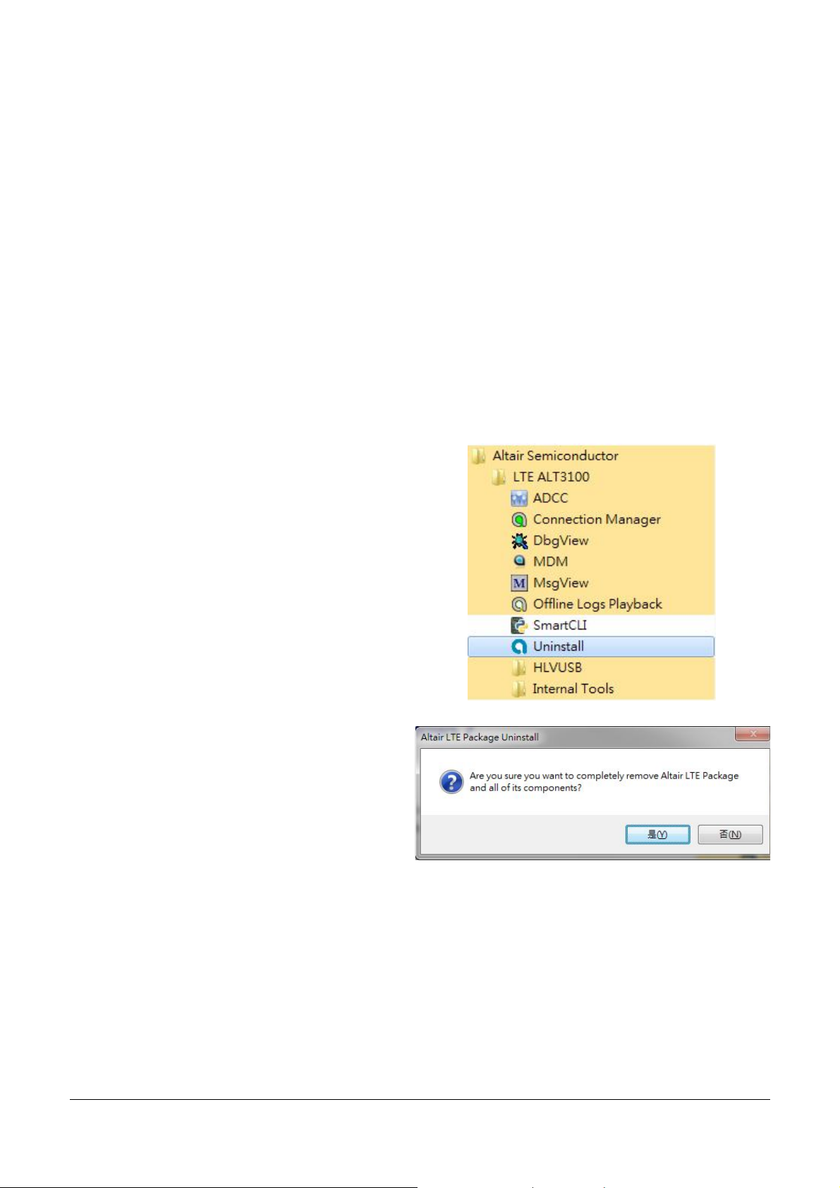
2.1.1. Windows 7 (32 bit)
1. Please click
StartProgramsAltair SemiconductorLTE
ALT3100Uninstall
2. Please click “Yes (Y)” button.
Page 5

Page
4
3. Please click “Uninstall” button.
4. Please wait a few seconds to complete
uninstallation.
5. Please click “Close” button.
6. Please click “OK” button.
7. Please click
“StartProgramsAltair SemiconductorLTE
ALT3100HLVUSBUninstall”.
8. Please click “YES (Y)” button.
9. Please reboot your computer after you have
completed the uninstallation.
Page 6
Page
5
2.2. Installation of drivers
2.2.1. Windows 7 (32 bit)
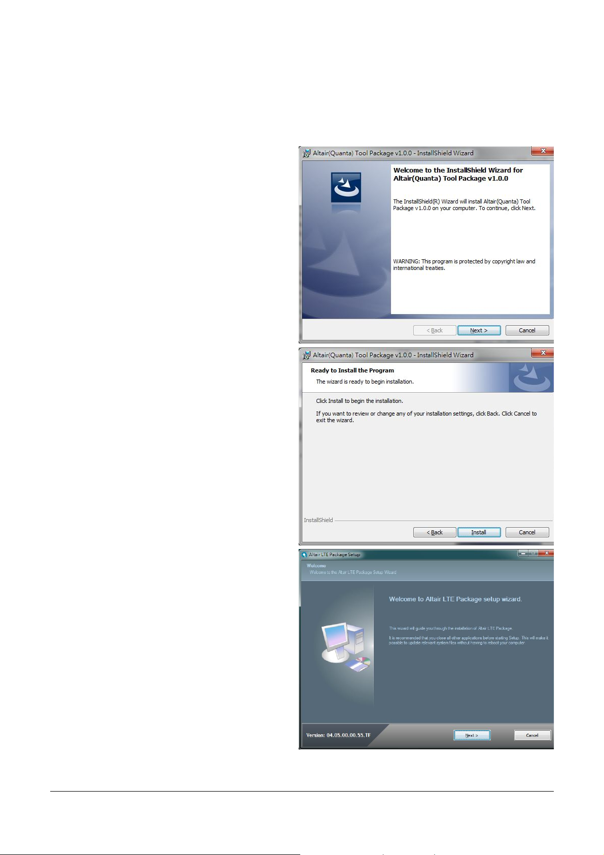
1. Please double clicks on “Altair(Quanta) Tool
Package v1.0.0.exe” to start installation.
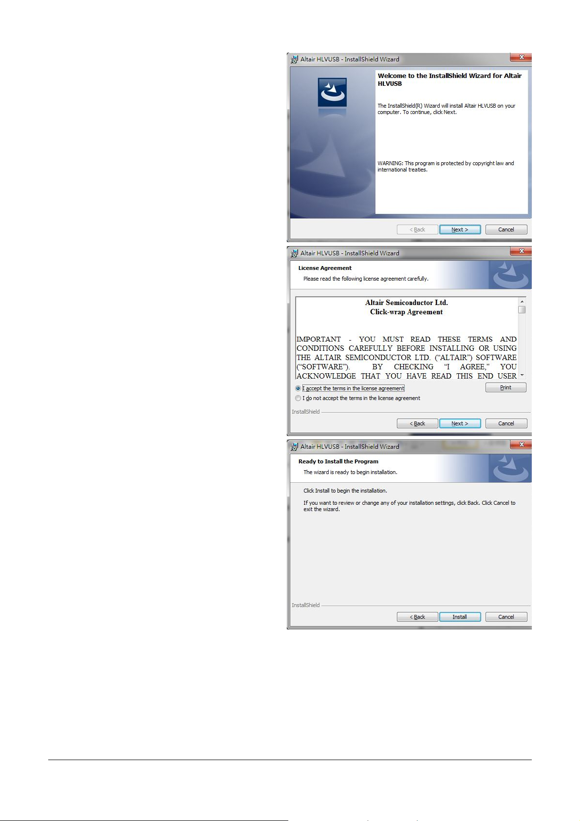
2. Please click “Next >” button.
3. Please click “Install” button.
4. It will take a few minutes to complete
installation.
5. Please click “Next >” button.
Page 7
Page
6
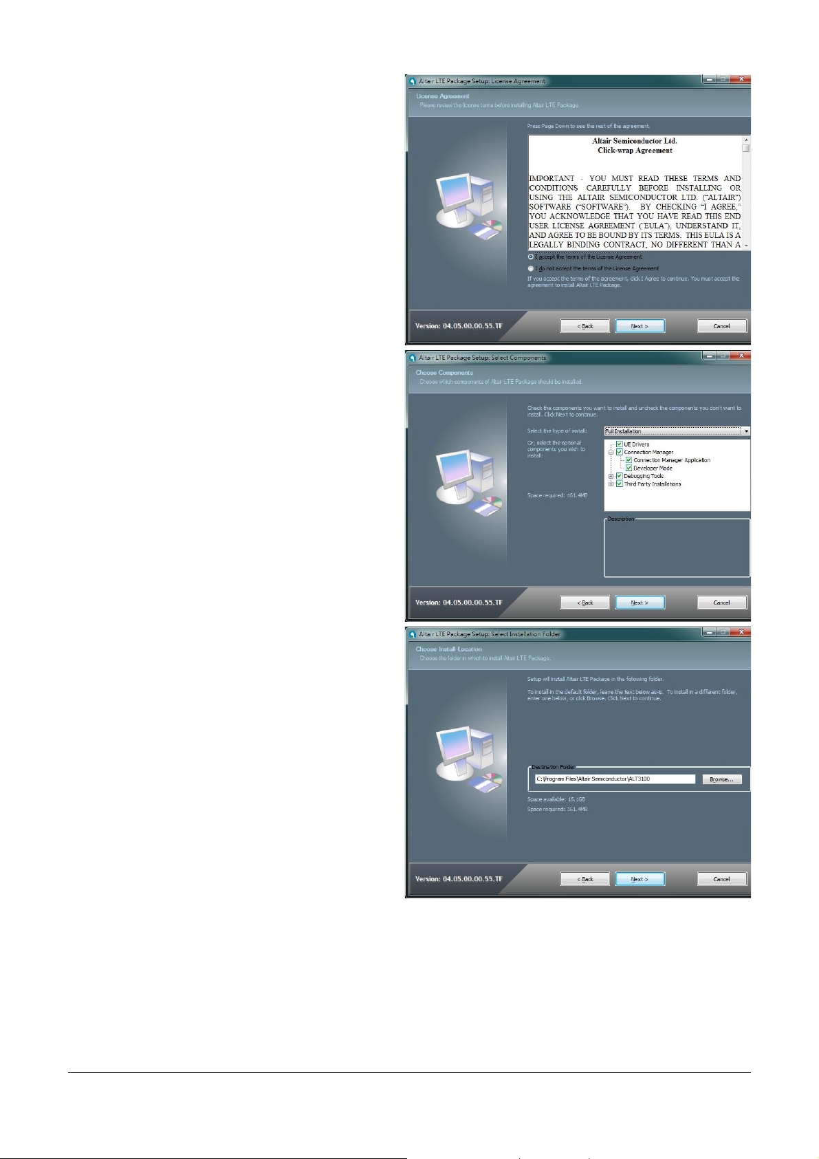
6. Please check “I accept the terms in the license
agreement”.
7. Please click “Next >” button.
8. Please select “Full Installation” type.
9. Please click “Next >” button.
10. Please click “Next >” button.
Page 8
Page
7
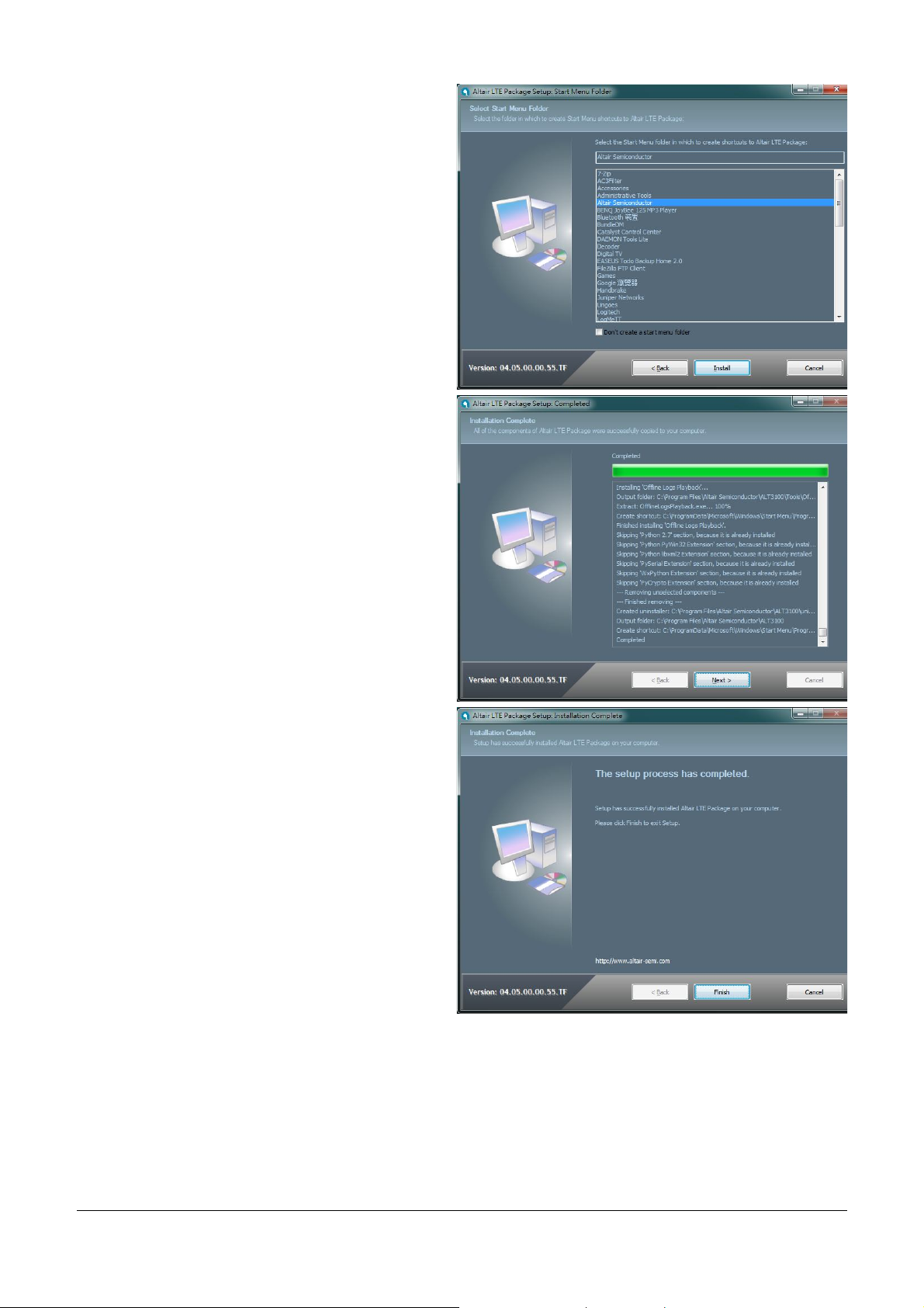
11. Please click “Install” button.
12. Please click “Next >” button.
13. Please click “Finish” button.
Page 9
Page
8
14. Please click “Next >” button.
15. Please check “I accept the terms in the license
agreement”.
16. Please click “Next >” button.
17. Please click “Install” button.
Page 10
Page
9
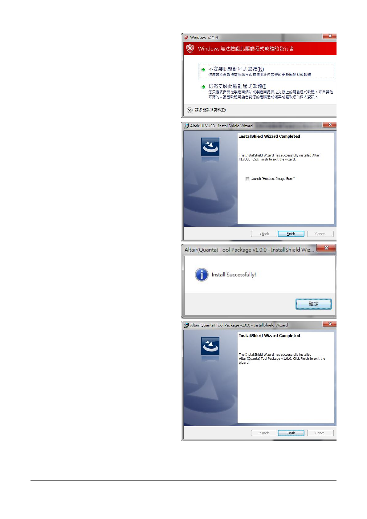
18. Please click “Continue to install driver anyway
(I)”.
19. Please click “Continue to install driver anyway
(I)”.
20. Please click “Continue to install driver anyway
(I)”.
21. Please click “Continue to install driver anyway
(I)”.
22. Please un-check “Launch “Hostless Image
Burn””.
23. Please click “Finish” button to complete driver
installation.
24. Please click “OK” button.
25. Please click “Finish” button.
Page 11

Page
10
out and plug in
26. Please plug in Quanta device and please be
patient and wait a few minutes to complete
driver installation.
27. Please click “Close (C)” button.
28. Please reset Quanta device (take
the usb cable), it will take about 50 seconds for
Quanta embedded system to be ready.
Page 12

Page
11
3. Operation of Connection Manager
3.1. Windows 7 (32 bit)
3.1.1. Basic Configuration
1. In order to get information from our
embedded connection manager, it’s
mandatory to configure as the following
instructions.
2. Please click
StartProgramsAltair SemiconductorLTE
ALT3100Connection Manager.
3. Please right click on top of connection manager
and select
OptionsDevice LocationTechnician PC.
4. Connection manager will pop out window for
you to enter IP and port.
5. Please enter IP address “10.0.0.1”. (see NOTE)
6. Please click “OK” button.
NOTE: If you have successfully installed Quanta
LI172 device, the embedded module will generate
DHCP server and its IP address is “10.0.0.1”.
Meanwhile, our Quanta device will get a DHCP
address “10.0.0.133” automatically.
Page 13

Page
12
7. Please check if connection manager shows
device information correctly and the red Altair
logo turns into yellow color.
Page 14

Page
13
3.1.2. Extended Information
1. Please right click on top of connection manager
and select
ViewExtended Information.
2. Connection manager will pop out “Extended
Information” window.
3. It’s NOT mandatory to set up this
“Configuration” tab, connection manager will
scan all the supported frequency bands and try
to connect to the network.
Page 15

Page
14
4. The “Extended Data” tab shows information of
Connection Status, APN, Transmission mode,
Bandwidth, DL EARFCN, Band, PLMN and
Physical Cell ID and so on.
5. The “At Commands” tab will allow you to send
AT Commands sets to configure supported
functional parameters or to get supported
information you want.
Page 16

Page
15
3.1.3. LTE Manager
1. Please right click on top of connection manager
and select
ViewLTE Manager.
2. Connection manager will pop out a “Supervisor
Password” window.
3. Please input “123456” and click “OK” button.
4. It will pop out a “LTE Manager” window.
5. LTE Manager shows information about
GeneralInfo, LogCreator, Dispatcher, Relay, and
GPS Tool.
Page 17

Page
16
3.1.4. Manual PLMN
1. Please right click on top of connection manager
and select
Manual PLMN.
2. Connection manager will pop out a “Plmn
Search” window.
3. It’s not necessary for you to select PLMN
manually if you want to connect to network.
Page 18

Page
17
3.1.5. Change to Commercial Mode
1. Please right click on top of connection manager
and select
“Change to Commercial Mode”.
2. Connection manager will pop out a “User Mode
Changed” dialog.
3. Please click “YES (Y)” button.
4. Please wait a few seconds for device to be
ready.
Page 19

Page
18
3.1.6. Disable Polling
1. Please right click on top of connection manager
and select
“OptionsDisable Polling”.
2. Connection manager will stop searching for
available network.
Page 20

Page
19
3.1.7. PIN Management
1. Please right click on top of connection manager
and select
“OptionsPIN ManagementPIN Information”
to get PIN information.
2. Connection manager will pop out “PIN
Information” window.
3. Please click “OK” button.
4. You also can enable PIN usage by right click on
top of connection manager and select
“OptionsPIN ManagementEnable PIN
Usage”.
5. Please input correct PIN code and click “OK”
button.
Page 21

Page
20
3.1.8. Automatic Connect Mode
1. Please right click on top of connection manager
and select
“OptionsAutomatic Connect Mode” to switch
connection manager from manual connect
mode to automatic connect mode.
2. Connection manager will automatically connect
to network.
Page 22

Page
21
3.1.9. Device Location
1. For Quanta hostless device, please use
“Technician PC” only.
2. Please right click on top of connection manager
and select
“OptionsDevice LocationTechnician PC”.
3. Please set IP address to “10.0.0.1” and click
“OK” button.
4. Connection manager will get information from
Quanta hostless device.
Page 23

Page
22
3.1.10. Help
1. Please right click on top of connection manager
and select
“HelpAbout”.
2. Connection manager will pop out a “LTE Card
Info” message box.
3. It will show information of IMSI number, IMEI
number, Supported Bands, Current firmware
version, and System package version.
4. Please click “OK” button.
5. Please right click on top of connection manager
and select
“HelpShow Versions”.
6. Connection manager will pop out a “Version
info” message box.
7. It will show information of System release
version, SWInfra release version, and Current
firmware version.
8. Please click “OK” button.
Page 24

Page
23
3.1.11. Reset
1. Please right click on top of connection manager
and select
“Reset”.
2. Connection manager will pop out a “” message
box.
Page 25

Page
24
4. Diagnostic Tool
4.1. MsgView
1. Please open MsgView by clicking
StartProgramsAltair SemiconductorLTE
ALT3100MsgView.
2. Please click “Start Logging” button to start
message logging.
3. Please plug in Quanta device and wait a few
seconds for device to be ready.
4. Once you find an issue, please stop testing and
data logging, please save log file and send it to
Quanta.
Page 26

Page
25
4.2. DbgView
1. Please open DbgView by clicking
StartProgramsAltair SemiconductorLTE
ALT3100DbgView.
2. Please plug in Quanta device and wait a few
seconds for device to be ready, and the
DbgView will start data logging.
3. Please click “Save” button to save log to a file.
4. Once you find any issue, please stop testing and
data logging, and please send this log file to
Quanta.
Page 27

Page
26
5. Firmware Upgrade
5.1. Image Burn Tool
1. Please click
StartProgramsAltair SemiconductorLTE
ALT3100HLVUSBImage Burn Tool.
2. Please check “U-Boot Env”.
3. Please check “U-Boot”.
4. Please check “Linux”.
5. Please check “File System”.
6. Please check “NVM”.
7. Please click “Start” button to start firmware
upgrade process.
8. Please click “YES (Y)” button.
Page 28

Page
27
9. It will show message “Waiting for device
reset …”.
10. The easiest way to reset device is to power cycle
device (i.e. to take out and plug in device).
11. If you are doing remote firmware upgrade
process, please follow the following procedure
to reset device.
12. Please open device manager and find network
interface of Quanta device “Remote NDIS based
Internet Sharing Device #”.
13. Please disable this network interface by right
click on it.
14. Please enable this device again.
15. Please find your Gadget Serial COM port
number (for example, COM112).
Page 29

Page
28
16. Please open COM112 COM port (for example,
open it by putty.exe)
17. Please select “Serial” as your “Connection type”.
18. Please fill in “COM112” as your “Serial line”.
19. Please click “Open” button to set up
connection.
20. Please enter “at”.
21. Please check if it responds with “OK”.
22. Please enter “atz” AT command to reboot
Quanta device.
23. After Quanta device reboots successfully, the
“Image Burn Tool” will start to do firmware
upgrade process.
24. Please make sure you Quanta device has
finished the firmware upgrade process with “---Finished ----“.
25. Please close “Image Burn Tool”.
26. Please take out and plug in Quanta device.
Page 30

Page
29
27. In order to recover the original calibration data,
please use ADCC tool.
28. After the device reboot successfully, please
open “Altair Device Control Center” by clicking,
StartProgramsAltair SemiconductorLTE
ALT3100ADCC.
29. Please click “Open Connection” and wait for a
few minutes.
30. Please click “BSP DB” tab.
31. Please select “Boot Parameters (Boot Bp).
32. Please select “From File”.
33. Please click Read DB and find the source DB and
click “Open” button to read it.
34. Please click “Burn DB” button to start burning.
35. Please repeat this procedure to burn the other
DBs.
Page 31

Page
30
6. OMA-DM
6.1. Mandatory Configuration
1. It’s necessary to configure Quanta device with
the following parameters before you start
OMA-DM testing.
2. It’s mandatory to configure Quanta device
with the following parameters if your device is
upgraded to new firmware.
3. Please make sure that the device is not
connected to LTE network (i.e. offline from
eNodeB) before you do any configuration.
4. Please open connection manager.
5. Please enter the following AT commands
sequentially (Please refer section 3.1.2).
AT%SETCFG="enable_test_mode","0"
AT%SETCFG="vzw_mode","1"
AT%SETACFG=ecm.Mode.VzwMode,true
AT%SETACFG=ecm.Mode.VzwImsTestMode,false
6. Please check if it returns “OK”.
7. Please confirm your configuration by entering
the following AT commands sequentially.
AT%GETCFG="enable_test_mode"
(it shall be “0”)
AT%GETCFG="vzw_mode"
(it shall be “1”)
AT%GETACFG=ecm.Mode.VzwMode
(it shall be “true”)
AT%GETACFG=ecm.Mode.VzwImsTestMode
(it shall be “false”)
Page 32

Page
31
6.2. How to Enable/Disable APN
1. Please make sure your device has disconnected
from network.
2. If you would like to edit APN table, it’s
necessary to telnet to embedded connection
manager. (Please refer to section 3.1.1)
3. Please open command console.
4. Please key in “telnet 10.0.0.1” and press enter.
5. If you failed to telnet 10.0.0.1, please manually
set your IP address to 10.0.0.133.
6. After successfully telnet to 10.0.0.1, please key
in “cat /etc/config/APNTable” and press enter.
7. There are 4 APNs in table, and you can see its
configurations, including NAME, IP_Type,
P_CSCF and so on.
8. For example, if you would like to disable
“VZWIMS” APN, please use the editor tool “vi”
to edit this APNTable.
9. Therefore, please key in
“vi /etc/config/APNTable” and press enter.
Page 33

Page
32
10. Please move cursor to
Option Enabled “true”
11. Please modify this value to “false”.
NOTE: If you are not familiar with vi
commands, please refer to section 6.6 for
more information.
12. Please enter “Shift+z” twice to save file.
13. Please key in
“cat /etc/config/APNTable” and press enter.
14. Please check if “VZWIMS” APN is disabled.
Option Enabled ‘false’
15. Please enter “reboot” command to reboot
device in order to take effect of the
configuration.
16. You can also follow above procedures to
enable/disable other APNs.
NOTE: Please make sure to reboot device in
order to take effect of your setting.
Page 34

Page
33
connection
6.3. How to Modify OMA-DM Server URL
1. Please make sure your device has disconnected
from network.
2. If you would like to edit OMA-DM server URL,
it’s necessary to telnet to embedded
manager. (Please refer to section 3.1.1)
3. Please open command console.
4. Please key in “telnet 10.0.0.1” and press enter.
5. If you failed to telnet 10.0.0.1, please manually
set your IP address to 10.0.0.133.
6. Please key in
“vi etc/config/service” and press enter.
7. Please modify the server URL to
”ivzwmdmii.iot.motive.com”
8. Please enter “Shift+z” twice to save file.
9. Please key in “cat /etc/config/service” and
check if the server URL is set up correctly.
10. Please key in
“vi etc/config/vdmc/tree-motive.xml”
and press enter.
11. Please key in “/https” to search the server URL.
12. Please modify the server URL to
https://ivzwmdmii.iot.motive.com/southbound-con
nector/dm
Page 35

Page
34
13. Please also check if port number is “443”.
14. Please enter “Shift+z” twice to save file.
Page 36

Page
35
lease check if your device has connected to LTE
6.4. How to Online Enable/Disable Internet APN
1. P
network successfully.
2. If you would like to online enable/disable
“INTERNET” APN (see NOTE), it’s necessary to
enter specific AT command.
NOTE: Online enable/disable “INTERNET” APN
means it’s not mandatory to reboot device to
take effect of “INTERNET” APN. Please note
that this method is applicable to “INTERNET”
APN only, and this configuration will be lost
after device reboots.
3. If you enter “at%dpdnact=0” to disable
“INTERNET” APN, the LTE connection will be
lost. On the contrary, if you enter
“at%dpdnact=1” to enable “INTERNET” APN,
device will reconnect to LTE network.
Page 37

Page
36
6.5. How to Enable/Disable OMA-DM log
1. Please make sure your device has disconnected
from network.
2. If you would like to enable/disable OMA-DM
log, it’s necessary to telnet to embedded
connection manager. (Please refer to section
3.1.1)
3. Please open command console.
4. Please key in “telnet 10.0.0.1” and press enter.
5. If you failed to telnet 10.0.0.1, please manually
set your IP address to 10.0.0.133.
6. Please key in
“vi etc/config/service” and press enter.
7. Please modify the value of DebugLevel to
“debug”.
8. Please enter “Shift+z” twice to save file.
9. Please enter “reboot” command to reboot
device.
10. Please enter “cat /tmp/vdm.log” and check
OMA-DM logs.
Page 38

Page
37
6.6. How to Use VI editor
Please google search “vi manual” or by clicking below URL directly.
http://glaciated.org/vi/
Page 39

Page
38
FCC Regulations:
This device complies with part 15 of the FCC Rules. Operation is subject to the following two
conditions: (1) This device may not cause harmful interference, and (2) this device must accept any
interference received, including interference that may cause undesired operation.
This device has been tested and found to comply with the limits for a Class B digital device, pursuant to
Part 15 of the FCC Rules. These limits are designed to provide reasonable protection against harmful
interference in a residential installation. This equipment generates, uses and can radiated radio frequency
energy and, if not installed and used in accordance with the instructions, may cause harmful interference to
radio communications. However, there is no guarantee that interference will not occur in a particular
installation if this equipment does cause harmful interference to radio or television reception, which can be
determined by turning the equipment off and on, the user is encouraged to try to correct the interference by
one or more of the following measures:
-Reorient or relocate the receiving antenna.
-Increase the separation between the equipment and receiver.
-Connect the equipment into an outlet on a circuit different from that to which the receiver is connected.
-Consult the dealer or an experienced radio/TV technician for help.
Changes or modifications not expressly approved by the party responsible for compliance could void the
user‘s authority to operate the equipment.
RF Exposure Information
This Modular Approval is limited to OEM installation for mobile and fixed applications only. The
antenna installation and operating configurations of this transmitter, including any applicable source-based
time-averaging duty factor, antenna gain and cable loss must satisfy MPE categorical Exclusion
Requirements of §2.1091.
The antenna(s) used for this transmitter must be installed to provide a separation distance of at least 20 cm
from all persons, must not be collocated or operating in conjunction with any other antenna or transmitter,
except in accordance with FCC multi-transmitter product procedures.
The end user has no manual instructions to remove or install the device and a separate approval is required
for all other operating configurations, including portable configurations with respect to 2.1093 and
different antenna configurations.
Maximum antenna gains allowed for use with this device are 3.82 dBi for band 13 and 5.82 dBi for band
4.
When the module is installed in the host device, the FCC ID label must be visible through a window on
the final device or it must be visible when an access panel, door or cover is easily re-moved. If not, a
second label must be placed on the outside of the final device that contains the following text: “Contains
FCC ID: HFS-LI172”.
 Loading...