


QuantaMesh
Ethernet Switch
Configuration Guide
QNOS5 NOS Platform

Version
Date
Description
Authors
1.0
15-Nov-2016
1. 1
st
release
Oliver Wu, James Chu,
WT Chou, and Thomas Lin
1.1
28-Mar-2017
1. New features added including BFD,
VRF Lite, LACP Fallback, and service
prohibit access
James Chu, Oliver and WT
Chou
REVISIONS
2

Contents
QuantaMesh Ethernet Switch Configuration Guide ............................................. 1
1. QuantaMesh QNOS5 Features ....................................................................... 19
1.1. Switching Features Introduction ............................................................................................ 19
1.1.1. VLAN Support ................................................................................................................................................... 19
1.1.2. Double VLANs ................................................................................................................................................... 19
1.1.3. Switching Modes .............................................................................................................................................. 19
1.1.4. Spanning Tree Protocols (STP) .......................................................................................................................... 19
1.1.5. Rapid Spanning Tree ......................................................................................................................................... 19
1.1.6. Multiple Spanning Tree ..................................................................................................................................... 19
1.1.7. Bridge Protocol Data Unit (BPDU) Guard ......................................................................................................... 20
1.1.8. BPDU Filtering .................................................................................................................................................. 20
1.1.9. Port-channel ..................................................................................................................................................... 20
1.1.10. Link Aggregate Control Protocol (LACP) ........................................................................................................... 20
1.1.11. Multi Chass Link Aggregation Group (MLAG) ................................................................................................... 20
1.1.12. Flow Control Support (IEEE 802.3x) .................................................................................................................. 20
1.1.13. Asymmetric Flow Control .................................................................................................................................. 21
1.1.14. Alternate Store and Forward (ASF) ................................................................................................................... 21
1.1.15. Jumbo Frames Support ..................................................................................................................................... 21
1.1.16. Auto-MDI/MDIX Support .................................................................................................................................. 21
1.1.17. Unidirectional Link Detection (UDLD) ............................................................................................................... 21
1.1.18. Expandable Port Configuration ........................................................................................................................ 21
1.1.19. VLAN-aware MAC-based Switching .................................................................................................................. 22
1.1.20. Back Pressure Support ...................................................................................................................................... 22
1.1.21. Auto Negotiation .............................................................................................................................................. 22
1.1.22. Storm Control ................................................................................................................................................... 22
1.1.23. Port Mirroring ................................................................................................................................................... 22
1.1.24. sFlow ................................................................................................................................................................. 23
1.1.25. Static and Dynamic MAC Address Tables ......................................................................................................... 23
1.1.26. Link Layer Discovery Protocol (LLDP) ................................................................................................................ 23
1.1.27. Link Layer Discovery Protocol (LLDP) for Media Endpoint Device ..................................................................... 23
1.1.28. DHCP Layer 2 Relay ........................................................................................................................................... 23
1.1.29. MAC Multicast Support .................................................................................................................................... 24
1.1.30. IGMP Snooping ................................................................................................................................................. 24
1.1.31. Source Specific Multicasting (SSM) ................................................................................................................... 24
1.1.32. Control Packet Flooding .................................................................................................................................... 24
3

1.1.33. Flooding to mRouter Ports ................................................................................................................................ 24
1.1.34. IGMP Snooping Querier .................................................................................................................................... 24
1.1.35. Management and Control Plane ACLs .............................................................................................................. 25
1.1.36. Remote Switched Port Analyzer (RSPAN) ......................................................................................................... 25
1.1.37. Link Dependency ............................................................................................................................................... 25
1.1.38. IPv6 Router Advertisement Guard .................................................................................................................... 25
1.1.39. FIP Snooping ..................................................................................................................................................... 26
1.1.40. ECN Support ...................................................................................................................................................... 26
1.2. Security Features ................................................................................................................... 26
1.2.1. Configurable Access and Authentication Profiles ............................................................................................. 26
1.2.2. AAA Command Authorization ........................................................................................................................... 27
1.2.3. Password-protected Management Access ....................................................................................................... 27
1.2.4. Strong Password Enforcement ......................................................................................................................... 27
1.2.5. MAC-based Port Security .................................................................................................................................. 27
1.2.6. RADIUS Client.................................................................................................................................................... 27
1.2.7. TACACS+ Client ................................................................................................................................................. 27
1.2.8. Dot1x Authentication (IEEE 802.1X) ................................................................................................................. 27
1.2.9. MAC Authentication Bypass ............................................................................................................................. 28
1.2.10. DHCP Snooping ................................................................................................................................................. 28
1.2.11. Dynamic ARP Inspection ................................................................................................................................... 28
1.2.12. IP Source Address Guard ................................................................................................................................... 28
1.2.13. Service Prohibit Access ..................................................................................................................................... 28
1.3. Quality of Service Features .................................................................................................... 28
1.3.1. Access Control Lists (ACL) ................................................................................................................................. 29
1.3.2. ACL Remarks ..................................................................................................................................................... 29
1.3.3. ACL Rule Priority ............................................................................................................................................... 29
1.3.4. Differentiated Service (DIffServ) ....................................................................................................................... 29
1.3.5. Class of Service (CoS) ........................................................................................................................................ 29
1.4. Management Features ........................................................................................................... 29
1.4.1. Management Options ....................................................................................................................................... 29
1.4.2. Management of Basic Network Information .................................................................................................... 30
1.4.3. Dual Software Images ...................................................................................................................................... 30
1.4.4. File Management.............................................................................................................................................. 30
1.4.5. FTP File Management ....................................................................................................................................... 30
1.4.6. Malicious Code Detection ................................................................................................................................. 30
1.4.7. Automatic Installation of Firmware and Configuration .................................................................................... 30
1.4.8. Warm Reboot ................................................................................................................................................... 31
4

1.4.9. SNMP Alarms and Trap Logs ............................................................................................................................ 31
1.4.10. Remote Monitoring (RMON) ............................................................................................................................ 31
1.4.11. Statistics Application ........................................................................................................................................ 31
1.4.12. Log Messages ................................................................................................................................................... 31
1.4.13. System Time Management ............................................................................................................................... 32
1.4.14. Source IP Address Configuration ...................................................................................................................... 32
1.4.15. Multiple Linux Routing Tables .......................................................................................................................... 32
1.4.16. Core Dump ........................................................................................................................................................ 32
1.4.16.1. Core Dump File Handling .............................................................................................................................. 32
1.4.17. Open Network Install Environment Support ..................................................................................................... 32
1.4.18. Interface Error Disable and Auto Recovery ....................................................................................................... 33
1.5. Routing Features .................................................................................................................... 33
1.5.1. IP Unnumbered ................................................................................................................................................. 33
1.5.2. Open Shortest Path First (OSPF) ....................................................................................................................... 33
1.5.3. Border Gateway Partol (BGP) ........................................................................................................................... 33
1.5.4. VLAN Routing .................................................................................................................................................... 34
1.5.5. IP Configuration ................................................................................................................................................ 34
1.5.6. Address Resolution Protocol (ARP) Table Management ................................................................................... 34
1.5.7. BOOTP/DHCP Relay Agent ................................................................................................................................ 35
1.5.8. IP Helper and UDP Relay ................................................................................................................................... 35
1.5.9. Routing Table.................................................................................................................................................... 35
1.5.10. Virtual Router Redundancy Protocol (VRRP) .................................................................................................... 35
1.5.11. Algorithmic Longest Prefex Match (ALPM) ....................................................................................................... 35
1.5.12. Bidirectional Forwarding Detection .................................................................................................................. 35
1.5.13. VRF Lite Operation and Configuration .............................................................................................................. 36
1.6. Layer 3 Multicast Features ..................................................................................................... 36
1.6.1. Internet Group Management Protocol ............................................................................................................. 36
1.6.2. Protocol Independent Multicast ....................................................................................................................... 36
1.6.2.1. Dense Mode ((PIM-DM) ................................................................................................................................ 36
1.6.2.2. Spare Mode (PIM-SM) .................................................................................................................................. 36
1.6.2.3. Source Specific Multicast (PIM-SSM) ............................................................................................................ 36
1.6.2.4. PIM IPv6 Support .......................................................................................................................................... 37
1.6.3. MLD/MLDv2 (RFC2710/RFC3810) .................................................................................................................... 37
1.7. Data Center Features ............................................................................................................. 37
1.7.1. Priority-based Flow Control .............................................................................................................................. 37
1.7.2. Data Center Bridging Exchange Protocol.......................................................................................................... 37
1.7.3. CoS Queuing and Enhanced Transmission Selection......................................................................................... 37
5

1.7.4. VXLAN Gateway ................................................................................................................................................ 38
2. Getting Started .............................................................................................. 39
2.1. Accessing the switch Command-Line Interface ..................................................................... 39
2.1.1. Connecting to the Switch Console .................................................................................................................... 39
2.2. Accessing the Switch CLI Through the Network .................................................................... 40
2.2.1. Using the Service Port or Management VLAN Interface for Remote Management ......................................... 40
2.2.1.1. Configuring Service Port Information ........................................................................................................... 41
2.2.1.2. Configuring the In-Band Management Interface ......................................................................................... 41
2.2.2. DHCP Option 61 ................................................................................................................................................ 42
2.2.2.1. Configuring DHCP Option 61 ........................................................................................................................ 42
2.3. Booting the Switch ................................................................................................................. 43
2.3.1. Utility Menu Functions...................................................................................................................................... 44
2.3.1.1. Start QNOS5 Application .............................................................................................................................. 45
2.3.1.2. Update Image ............................................................................................................................................... 45
2.3.1.3. Load Configuration ....................................................................................................................................... 47
2.3.1.4. Select Serial Speed ........................................................................................................................................ 48
2.3.1.5. Retrieve Error Log ......................................................................................................................................... 48
2.3.1.6. Erase Current Configuration ......................................................................................................................... 49
2.3.1.7. Erase Permanent Storage ............................................................................................................................. 49
2.3.1.8. Select Boot Method ...................................................................................................................................... 49
2.3.1.9. Activate Backup Image ................................................................................................................................. 50
2.3.1.10. Start Diagnostic Application ......................................................................................................................... 50
2.3.1.11. Reboot .......................................................................................................................................................... 50
2.3.1.12. Erase All Configuration Files ......................................................................................................................... 50
2.4. Understanding the User Interfaces ........................................................................................ 50
2.4.1. Using the Command-Line Interface .................................................................................................................. 51
2.4.2. Using SNMP ...................................................................................................................................................... 51
2.4.2.1. SNMPv3 ........................................................................................................................................................ 52
2.4.2.2. SNMP Configuration example....................................................................................................................... 52
3. Configuring L2 Switching Features ................................................................. 57
3.1. VLANs 57
3.1.1. VLAN Tagging ................................................................................................................................................... 58
3.1.2. Double-VLAN Tagging....................................................................................................................................... 58
3.1.3. Default VLAN Behavior ..................................................................................................................................... 59
3.1.4. VLAN Configuration Example ........................................................................................................................... 60
3.1.4.1. Configuring the VLANs and Ports on Switch 1 .............................................................................................. 62
6

3.1.4.2. Configuring the VLANs and Ports on Switch 2 .............................................................................................. 64
3.2. Switchport Modes .................................................................................................................. 64
3.3. Port-channels – Operation and Configuration ...................................................................... 66
3.3.1. Static and Dynamic Port-channel ..................................................................................................................... 66
3.3.2. Port-channel Hashing ....................................................................................................................................... 66
3.3.2.1. Resilient Hasing ............................................................................................................................................ 67
3.3.2.2. Hash Prediction with ECMP and Port-channel .............................................................................................. 67
3.3.3. Port-channel Interface Overview ...................................................................................................................... 68
3.3.4. Port-channel Interaction with Other Features .................................................................................................. 68
3.3.4.1. VLAN ............................................................................................................................................................. 68
3.3.4.2. STP ................................................................................................................................................................ 69
3.3.4.3. Statistics ....................................................................................................................................................... 69
3.3.5. Port-channel Configuration Guidelines ............................................................................................................. 69
3.3.5.1. Port-channel Configuration Examples .......................................................................................................... 69
3.3.5.2. Configuration Dynamic Port-channels .......................................................................................................... 70
3.3.5.3. Configuration Static Port-channels ............................................................................................................... 71
3.4. LACP Fallback Configuration .................................................................................................. 72
3.4.1. Configuring Dynamic Port-channels ................................................................................................................. 72
3.4.2. Configuring Static Port-channels ...................................................................................................................... 73
3.5. MLAG – Operation and Configuration ................................................................................... 74
3.5.1. Overview ........................................................................................................................................................... 75
3.5.2. Deployment Scenarios ...................................................................................................................................... 75
3.5.2.1. Definitions..................................................................................................................................................... 76
3.5.2.2. Configuration Consistency ............................................................................................................................ 77
3.5.3. MLAG Fast Failover ........................................................................................................................................... 79
3.5.4. MLAG Configuration ......................................................................................................................................... 79
3.6. Unidirectional Link Detection (UDLD) .................................................................................... 82
3.6.1. UDLD Modes ..................................................................................................................................................... 82
3.6.2. UDLD and Port-channel Interfaces ................................................................................................................... 82
3.6.3. Configuring UDLD ............................................................................................................................................. 82
3.7. Port Mirroring ........................................................................................................................ 84
3.7.1. Configuring Port Mirroring ............................................................................................................................... 84
3.7.2. Configuring RSPAN ........................................................................................................................................... 85
3.7.2.1. Configuration on the Source Switch (SW1) ................................................................................................... 85
3.7.2.2. Configuration on the Intermediate Switch (SW2) ......................................................................................... 86
3.7.2.3. Configuration on the Destination Switch (SW3) ........................................................................................... 87
7

3.7.3. VLAN-based Mirroring ...................................................................................................................................... 87
3.7.4. Flow-based Mirroring ....................................................................................................................................... 87
3.8. Spanning Tree Protocol .......................................................................................................... 88
3.8.1. Classic STP, Multiple STP, and Rapdi STP .......................................................................................................... 88
3.8.2. STP Operation ................................................................................................................................................... 88
3.8.3. MSTP in the Network ........................................................................................................................................ 89
3.8.4. Optional STP Features ...................................................................................................................................... 92
3.8.4.1. BPDU Flooding .............................................................................................................................................. 92
3.8.4.2. Edge Port ...................................................................................................................................................... 92
3.8.4.3. PDU Filtering ................................................................................................................................................. 92
3.8.4.4. Root Guard ................................................................................................................................................... 93
3.8.4.5. Loop Guard ................................................................................................................................................... 93
3.8.4.6. BPDU Protection ........................................................................................................................................... 93
3.8.5. STP Configuring Examples ................................................................................................................................ 94
3.8.5.1. Configuring STP ............................................................................................................................................ 94
3.8.5.2. Configuring MSTP ......................................................................................................................................... 95
3.9. IGMP Snooping ...................................................................................................................... 97
3.9.1. IGMP Snooping Querier .................................................................................................................................... 97
3.9.2. Configuring IGMP Snooping ............................................................................................................................. 97
3.9.3. IGMPv3/SSM Snooping ................................................................................................................................... 100
3.10. MLD Snooping .................................................................................................. 101
3.10.1. MLD Snooping Configuration Example ........................................................................................................... 101
3.10.1.1. MLD Snooping Configuration Example ....................................................................................................... 102
3.10.1.2. MLD Snooping Verification Example .......................................................................................................... 103
3.10.2. MLD Snooping First Leave Configuration Example ......................................................................................... 103
3.10.2.1. MLD Snooping Configuration...................................................................................................................... 104
3.10.3. MLD Snooping Querier Configuration Example .............................................................................................. 104
3.11. LLDP and LLDP-MED ......................................................................................... 106
3.11.1. LLDP and Data Center Application .................................................................................................................. 106
3.11.2. Configuring LLDP ............................................................................................................................................ 106
3.12. sFlow ................................................................................................................. 108
3.12.1. sFlow Sampling ............................................................................................................................................... 109
3.12.1.1. Packet Flow Sampling ................................................................................................................................. 110
3.12.1.2. Counter Sampling ....................................................................................................................................... 110
3.12.2. Configuring sFlow ........................................................................................................................................... 110
3.13. Link Dependency .............................................................................................. 112
8

3.14. AR Guard........................................................................................................... 113
3.15. FIP Snooping ..................................................................................................... 113
3.16. ECN ................................................................................................................... 117
3.16.1. Enabling ECN in Microsoft Windows .............................................................................................................. 118
3.16.2. Example 1: SLA Example ................................................................................................................................. 118
3.16.3. Example 2: Data Cetner TCP (DCTCP) Configuration ...................................................................................... 121
4. Configuring Security Features ...................................................................... 123
4.1. Controlling Management Access ......................................................................................... 123
4.1.1. Using RADIUS Servers for Management Security ........................................................................................... 123
4.1.1.1. RADIUS Dynamic Authorization .................................................................................................................. 124
4.1.2. Using TACACS+ to Control Management Access ............................................................................................ 126
4.1.3. Configuring and Applying Authentication Profiles.......................................................................................... 126
4.1.3.1. Configuring Authentication Profiles for Post-based Authentication ........................................................... 128
4.1.4. Configuring the Primary and Secondary RADIUS Servers ............................................................................... 128
4.1.5. Configuring an Authentication Profile ............................................................................................................ 129
4.2. Configuring DHCP Snooping, DAI, and IPSG ......................................................................... 130
4.2.1. DHCP Snooping Overview ............................................................................................................................... 130
4.2.1.1. Populating the DHCP Snooping Bindings Database .................................................................................... 131
4.2.1.2. DHCP Snooping and VLANs ......................................................................................................................... 131
4.2.1.3. DHCP Snooping Logging and Rate Limits.................................................................................................... 132
4.2.2. IP Source Guard Overview .............................................................................................................................. 132
4.2.2.1. IPSG and Port Security ................................................................................................................................ 132
4.2.3. Dynamic ARP Inspection Overview ................................................................................................................. 133
4.2.3.1. Optional DAI Features ................................................................................................................................ 133
4.2.4. Increasing Security with DHCP Snooping, DAI, and IPSG ................................................................................ 133
4.2.5. Configuring DHCP Snooping ........................................................................................................................... 134
4.2.6. Configuring IPSG ............................................................................................................................................. 135
4.3. ACLs 136
4.3.1. MAC ACLs ........................................................................................................................................................ 136
4.3.2. IP ACLs ............................................................................................................................................................ 137
4.3.3. ACL Redirect Function ..................................................................................................................................... 137
4.3.4. ACL Mirror Function ........................................................................................................................................ 138
4.3.5. ACL Logging .................................................................................................................................................... 138
4.3.6. Time-based ACLs ............................................................................................................................................. 138
4.3.7. ACL Rule Remarks ........................................................................................................................................... 139
4.3.8. ACL Rule Priority ............................................................................................................................................. 139
9

4.3.9. ACL Limitations ............................................................................................................................................... 139
4.3.10. ACL Configuration Process .............................................................................................................................. 140
4.3.11. Preventing False ACL Matches ........................................................................................................................ 140
4.3.12. IPv6 ACL Qualifies ........................................................................................................................................... 141
4.3.13. ACL Configuration Examples ........................................................................................................................... 141
4.3.13.1. Configuring an IP ACL ................................................................................................................................. 141
4.3.13.2. Configuring a MAC ACL ............................................................................................................................... 143
4.3.13.3. Configuring a Time-based ACL .................................................................................................................... 144
4.4. Control Plane Policing (CoPP) .............................................................................................. 145
4.4.1. CoPP Configuration Examples......................................................................................................................... 146
4.5. Service Prohibit Access ........................................................................................................ 148
4.5.1. Configuring Service Prohibit ........................................................................................................................... 148
5. Configuring Quality of Service ...................................................................... 149
5.1. CoS 149
5.1.1. Trusted and Untrusted Port Modes ................................................................................................................ 149
5.1.2. Traffic Shaping on Egress Traffic .................................................................................................................... 149
5.1.3. Defining Traffic Queues .................................................................................................................................. 149
5.1.3.1. Supported Queue Management Methods .................................................................................................. 150
5.1.3.2. CoS Configuration Example ........................................................................................................................ 150
5.2. DiffServ 152
5.2.1. DiffServ Functionality and Switch Roles.......................................................................................................... 153
5.2.2. Elements of DiffServ Configuration ................................................................................................................ 153
5.2.3. Configuration DiffServ to Provide Subnets Equal Access to External Network ............................................... 153
6. Configuring Switch Management Features ................................................... 156
6.1. Managing Images and Files .................................................................................................. 156
6.1.1. Supported File Management Methods ........................................................................................................... 156
6.1.2. Uploading and Downloading Files .................................................................................................................. 157
6.1.3. Managing Switch Software (Images) ............................................................................................................. 157
6.1.4. Managing Configuration Files ........................................................................................................................ 157
6.1.4.1. Editing and Downloading Configuration Files ............................................................................................ 158
6.1.4.2. Creating and Applying Configuration Scripts .............................................................................................. 158
6.1.4.3. Non-Disruptive Configuration Management .............................................................................................. 159
6.1.5. Saving the Running Configuration .................................................................................................................. 159
6.1.6. File and Image Management Configuration Examples .................................................................................. 159
6.1.7. Upgrading the Firmware ................................................................................................................................ 159
6.1.7.1. Managing Configuration Scripts ................................................................................................................. 162
10

6.2. Enabling Automatic Image Installation and System Configuration ..................................... 163
6.2.1. DHCP Auto Install Process............................................................................................................................... 164
6.2.1.1. Obtaining IP address Information .............................................................................................................. 164
6.2.1.2. Obtaining Other Dynamic Information ....................................................................................................... 164
6.2.1.3. Obtaining the Image ................................................................................................................................... 165
6.2.1.4. Obtaining the Configuration File ................................................................................................................ 165
6.2.2. Monitoring and Completing the DHCP Auto Install Process ........................................................................... 166
6.2.2.1. Saving a Configuration ............................................................................................................................... 167
6.2.2.2. Stopping and Restarting the Auto Install Process ....................................................................................... 167
6.2.2.3. Managing Downloaded Configuration Files ............................................................................................... 167
6.2.3. DHCP Auto Install Dependencies .................................................................................................................... 167
6.2.4. Default Auto Install Values ............................................................................................................................. 168
6.2.5. Enabling DHCP Auto Install and Auto Image Download ................................................................................. 168
6.3. Downloading a Core Dump .................................................................................................. 169
6.3.1. Using NFS to Download a Core Dump ............................................................................................................ 169
6.3.2. Using TFTP or FTP to Download a Core Dump ................................................................................................ 170
6.4. Setting the System Time ...................................................................................................... 170
6.4.1. Manual Time Configuration ............................................................................................................................ 171
6.4.2. Configuring SNTP ............................................................................................................................................ 172
6.5. Configuring System Log Example ......................................................................................... 172
6.5.1. Example 1 to Add Syslog Host ........................................................................................................................ 172
6.5.2. Example 2 to Verify Syslog Host Configuration .............................................................................................. 173
7. Configuring Routing ..................................................................................... 177
7.1. Basic Routing and Features .................................................................................................. 177
7.1.1. VLAN Routing .................................................................................................................................................. 177
7.1.1.1. When to Configure VLAN Routing .............................................................................................................. 178
7.1.2. IP Routing Configuration Example .................................................................................................................. 178
7.1.2.1. Configuring Switch A .................................................................................................................................. 179
7.1.2.2. Configuring Switch B ................................................................................................................................... 180
7.1.3. IP Unnumbered Configuration Example ......................................................................................................... 181
7.2. OSPF 183
7.2.1. Configuring an OSPF Border Router and Setting Interface Costs ................................................................... 184
7.3. VRRP 186
7.3.1. VRRP Operation in the Network ..................................................................................................................... 186
7.3.1.1. VRRP Router Priority ................................................................................................................................... 186
7.3.1.2. VRRP Preemption ........................................................................................................................................ 186
11

7.3.1.3. VRRP Accept Mode ..................................................................................................................................... 187
7.3.1.4. VRRP Route and Interface Tracking ............................................................................................................ 187
7.3.2. VRRP Configuration Example .......................................................................................................................... 187
7.3.2.1. VRRP with Load Sharing ............................................................................................................................. 188
7.3.2.2. VRRP with Route and Interface Tracking .................................................................................................... 190
7.4. IP Helper 193
7.4.1. Relay Agent Configuration Example ............................................................................................................... 195
7.5. Border Gateway Patrol (BGP) .............................................................................................. 197
7.5.1. BGP Topology ................................................................................................................................................. 197
7.5.1.1. External BGP Peering .................................................................................................................................. 198
7.5.1.2. Internal BGP Peering .................................................................................................................................. 198
7.5.1.3. Advertising Network Layer Reachability Information ................................................................................. 198
7.5.2. BGP Behavior .................................................................................................................................................. 199
7.5.2.1. BGP Route Selection ................................................................................................................................... 199
7.5.3. BGP Configuration Example ............................................................................................................................ 200
7.5.3.1. Configuring BGP on Router 9 ...................................................................................................................... 200
7.5.3.2. Configuring BGP on Router 3 ...................................................................................................................... 203
7.6. IPv6 Routing ......................................................................................................................... 204
7.6.1. How Does IPv6 Compare with IPv6 ................................................................................................................. 205
7.6.2. How are IPv6 Interface Configured ................................................................................................................. 205
7.6.3. Default IPv6 Routing Values ........................................................................................................................... 206
7.6.4. Configuring IPv6 Routing Features ................................................................................................................. 206
7.6.4.1. Configuring Global IP Routing Settings ....................................................................................................... 207
7.6.4.2. Configuring IPv6 Interface Settings ............................................................................................................ 207
7.6.4.3. Configuring IPv6 Neighbor Discovery ......................................................................................................... 208
7.6.4.4. Configuring IPv6 Route Table Entries and Route Preferences .................................................................... 210
7.6.4.5. IPv6 Show Commands ................................................................................................................................ 210
7.7. ECMP Hash Selection ........................................................................................................... 211
7.8. Bidirectional Forwarding Detection ..................................................................................... 211
7.8.1. Configuring BFD .............................................................................................................................................. 212
7.9. VRF Lite Operation and Configuration ................................................................................. 213
7.9.1. Route Leaking ................................................................................................................................................. 213
7.9.2. Adding Leaked Routes .................................................................................................................................... 214
7.9.3. Using Leaked Routes ....................................................................................................................................... 214
7.9.4. CPU-Originated Traffic.................................................................................................................................... 214
7.9.5. VRF Features Support ..................................................................................................................................... 214
12

7.9.6. VRF Lite Development Scenarios .................................................................................................................... 216
7.9.7. VRF Configuration Example ............................................................................................................................ 219
8. Configuring Multicast Routing ..................................................................... 221
8.1. L3 Multicast Overview ......................................................................................................... 221
8.1.1. IP Multicast Traffic ......................................................................................................................................... 221
8.1.2. Multicast Protocol Switch Support ................................................................................................................. 221
8.1.3. Multicast Protocol Roles ................................................................................................................................. 222
8.1.4. Multicast Switch Requirements ...................................................................................................................... 222
8.1.5. Determining which Multicast Protocols to Enable ......................................................................................... 222
8.1.6. Multicast Routing Tables ................................................................................................................................ 222
8.1.7. Multicast Tunneling ........................................................................................................................................ 222
8.1.8. IGMP ............................................................................................................................................................... 223
8.1.8.1. IGMP Proxy ................................................................................................................................................. 223
8.1.9. MLD Protocol .................................................................................................................................................. 223
8.1.9.1. Join Mechanism .......................................................................................................................................... 224
8.1.9.2. Leave Mechanism ....................................................................................................................................... 224
8.1.10. PIM Protocol ................................................................................................................................................... 224
8.1.10.1. Using PIM-SM as the Multicast Routing Protocol....................................................................................... 224
8.1.10.2. Using PIM-DM as the Multicast Routing Protocol ...................................................................................... 225
8.2. Default L3 Multicast Values ................................................................................................. 225
8.3. L3 Multicast Configuration Examples .................................................................................. 227
8.3.1. Configuring Multicast VLAN Routing with IGMP and PIM-SM ....................................................................... 227
8.3.2. Example 1: MLDv1 Configuration ................................................................................................................... 229
8.3.3. Example 2: MLDv2 Configuration ................................................................................................................... 230
8.3.4. Example 3: MLD Configuration Verification .................................................................................................. 230
9. Configuring Data Center Features ................................................................ 232
9.1. Data Center Technology Overview ...................................................................................... 232
9.2. Priority-based Flow Control ................................................................................................. 232
9.2.1. PFC Operation and Behavior ........................................................................................................................... 233
9.2.2. Configuring PFC .............................................................................................................................................. 233
9.3. Data Center Bridging Exchange Protocol ............................................................................. 234
9.3.1. Interoperability with IEEE DCBX ...................................................................................................................... 234
9.3.2. DCBX and Port Roles ....................................................................................................................................... 235
9.3.3. Configuration Source Port Selection Process .................................................................................................. 236
9.3.4. Configuring DCBX ........................................................................................................................................... 237
9.4. CoS Queuing ......................................................................................................................... 238
13

9.4.1. CoS Queuing Function and Behavior............................................................................................................... 239
9.4.1.1. Trusted Port Queue Mappings .................................................................................................................... 239
9.4.1.2. Un-trusted Port Default Priority ................................................................................................................. 239
9.4.1.3. Queue Configuration .................................................................................................................................. 239
9.4.1.4. Traffic Class Groups .................................................................................................................................... 240
9.4.2. Configuring CoS Queuing and ETS .................................................................................................................. 240
9.5. Enhanced Transmission Selection ........................................................................................ 243
9.5.1. ETS Operation and Dependencies ................................................................................................................... 243
9.6. VXLAN Gateway Operation and Configuration .................................................................... 243
9.6.1. Overview ......................................................................................................................................................... 243
9.6.1.1. VXLAN ......................................................................................................................................................... 244
9.6.2. Functional Description .................................................................................................................................... 244
9.6.2.1. VTEP to VN Association .............................................................................................................................. 244
9.6.2.2. Configuration of Remote VTEPs .................................................................................................................. 245
9.6.2.3. VTEP Nex-hop Resolution ........................................................................................................................... 246
9.6.2.4. VXLAN UDP Destination Port ...................................................................................................................... 246
9.6.2.5. Tunnels ....................................................................................................................................................... 246
9.6.2.6. MAC Learning and Aging ............................................................................................................................ 247
9.6.2.7. Host Configuration ..................................................................................................................................... 247
9.6.2.8. ECMP .......................................................................................................................................................... 248
9.6.2.9. MTU ............................................................................................................................................................ 248
9.6.2.10. TTL and DSCP/TOS ...................................................................................................................................... 248
9.6.2.11. Packet Forwarding ...................................................................................................................................... 249
9.6.3. VXLAN Configuration Examples ...................................................................................................................... 249
9.6.3.1. Unicast VXLAN Configuration ..................................................................................................................... 250
Appendix A: Term and Acronyms .................................................................... 254
14

LIST of FIGURES
Figure 2-1: SNMP Configuration Topology ............................................................................................. 52
Figure 3-1: Simple VLAN Topology ........................................................................................................ 58
Figure 3-2: Double VLAN Tagging Network Example .............................................................................. 59
Figure 3-3: Network Topology for VLAN Configuration .......................................................................... 61
Figure 3-4: Port-channel Configuration ................................................................................................. 66
Figure 3-5: STP Blocking........................................................................................................................ 75
Figure 3-6: MLAG in a Layer-2 Network ................................................................................................. 76
Figure 3-7: MLAG Components ............................................................................................................. 76
Figure 3-8: MLAG Configuration Diagram .............................................................................................. 79
Figure 3-9: UDLD Configuration Example ............................................................................................... 83
Figure 3-10: RSPAN Configuration Example ........................................................................................... 85
Figure 3-11: STP in a Small Bridged Network ......................................................................................... 89
Figure 3-12: Single STP Topology........................................................................................................... 90
Figure 3-13: Logical MSTP Environment ................................................................................................ 91
Figure 3-14: STP Example Network Diagram .......................................................................................... 94
Figure 3-15: MSTP Configuration Example ............................................................................................. 96
Figure 3-16: Switch with IGMP Snooping ............................................................................................... 98
Figure 3-17: MLD Snooping Topology .................................................................................................. 102
Figure 3-18: MLD Snooping Leave Configuration Topology................................................................... 104
Figure 3-19: MLD Snooping Querier Configuration Example ................................................................. 105
Figure 3-20: sFlow Architecture .......................................................................................................... 109
Figure 4-1: RADIUS Topology .............................................................................................................. 124
Figure 4-2: DHCP Binding .................................................................................................................... 131
Figure 4-3: DHCP Snooping Configuration Topology............................................................................. 134
Figure 4-4: IP ACL Example Network Diagram ...................................................................................... 142
15

Figure 4-5:CoPP Configuration Topology ............................................................................................. 146
Figure 5-1: CoS Mapping and Queue Configuration ............................................................................. 151
Figure 5-2: DiffServ Internet Access Example Network Diagram ........................................................... 154
Figure 6-1: System Log Topology ......................................................................................................... 173
Figure 6-2: Syslog Server Screen.......................................................................................................... 175
Figure 6-3: Syslog packet capture ........................................................................................................ 175
Figure 7-1: Inter-VLAN Routing ........................................................................................................... 178
Figure 7-2: IP Routing Example Topology ............................................................................................ 179
Figure 7-3: IP Unnumbered Configuration Example ............................................................................. 181
Figure 7-4: OSPF Area Border Router .................................................................................................. 184
Figure 7-5: VRRP with Load Sharing Network Diagram ......................................................................... 188
Figure 7-6: VRRP with Tracking Network Diagram ............................................................................... 190
Figure 7-7: L3 Relay Network Diagram ................................................................................................ 196
Figure 7-8: Example BGP Network ...................................................................................................... 198
Figure 7-9: BGP Configuration Example ............................................................................................... 200
Figure 7-10: VRF Scenarios ................................................................................................................. 217
Figure 7-11: VRF routing with shared services ..................................................................................... 217
Figure 8-1: Multicast VLAN Routing with IGMP and PIM-SM Example .................................................. 227
Figure 8-2: MLD Topology .................................................................................................................. 229
Figure 9-1: DCBX Configuration ........................................................................................................... 237
Figure 9-2: Unicast VXLAN Topology ................................................................................................... 250
16

LIST of TABLES
Table 3-1: VLAN default and maximum values ...................................................................................... 60
Table 3-2: Example VLAN ...................................................................................................................... 60
Table 3-3: Switch Port Configuration ..................................................................................................... 61
Table 3-4: Switchport Mode Behavior ................................................................................................... 65
Table 4-1: Authentication Method Summary....................................................................................... 127
Table 4-2: Common EtherType Numbers ............................................................................................. 140
Table 4-3: Common IP Protocol Numbers ............................................................................................ 141
Table 6-1: Files to Manage .................................................................................................................. 156
Table 6-2: Configuration File Possibilities ............................................................................................ 166
Table 6-3: TFTP Request Types ............................................................................................................ 166
Table 6-4: Auto Install Defaults ........................................................................................................... 168
Table 7-1: IP Routing Features ............................................................................................................ 177
Table 7-2: Default Ports – UDP Port Numbers Implied by Wildcard ...................................................... 193
Table 7-3: UDP Port Allocation............................................................................................................ 195
Table 7-4: IPv6 Routing Defaults ......................................................................................................... 206
Table 7-5: IPv6 Interface Defaults ....................................................................................................... 206
Table 7-6: Global IP Routing Settings .................................................................................................. 207
Table 7-7: IPv6 Interface Settings ........................................................................................................ 208
Table 7-8: IPv6 Neighbor Discovery Settings ........................................................................................ 209
Table 7-9: IPv6 Static Routes .............................................................................................................. 210
Table 7-10: IPv6 Configuration Status ................................................................................................. 211
Table 7-11: VRF features list .............................................................................................................. 216
Table 8-1: Multicast Protocol Support Summary ................................................................................. 221
Table 8-2: L3 Multicast Defaults .......................................................................................................... 226
Table 9-1: DCB Features ..................................................................................................................... 232
17

Table 9-2: 802.1p-to-TCG Mapping ..................................................................................................... 242
Table 9-3: TCG Bandwidth and Scheduling .......................................................................................... 242
Table 9-4: VLAN and VXLAN Comparison ............................................................................................. 250
Table 9-5: Terms and Acronyms .......................................................................................................... 254
Table 9-6: Terms and Acronyms (Cont.) ............................................................................................... 255
Table 9-7: Terms and Acronyms (Cont.) ............................................................................................... 256
18

1. QuantaMesh QNOS5 Features
This section provides a brief overview of the supported QNOS features. The features are categorized as
follows:
1.1. Switching Features Introduction
1.1.1. VLAN Support
VLANs are collections of switching ports that comprise a single broadcast domain. Packets are classified as
belonging to a VLAN based on either the VLAN tag or a combination of the ingress port and packet contents.
Packets sharing common attributes can be groups in the same VLAN. QNOS software is in full compliance
with IEEE 802.1Q VLAN tagging.
1.1.2. Double VLANs
The Double VLAN feature (IEEE 802.1QinQ) allows the use of a second tag on network traffic. The additional
tag helps differentiate between customers in the Metropolitan Area Networks (MAN) while preserving
individual customer’s VLAN identification when they enter their own 802.1Q domain.
1.1.3. Switching Modes
The switchport mode feature helps to minimize the potential for configuration errors. The feature also
makes VLAN configuration easier by reducing the amount of commands needed for port configuration. For
example, to configure a port connected to an end user, the administrator can configure the port in Access
mode. Ports connected to other switches can be configured in Trunk mode. VLAN assignments and tagging
behavior are automatically configured as appropriate for the connection type.
1.1.4. Spanning Tree Protocols (STP)
Spanning Tree Protocol (IEEE 802.1D) is a standard requirement of Layer 2 switches that allows bridges to
automatically prevent and resolve L2 forwarding loops. The STP feature supports a variety of per-port
settings including path cost, priority settings, Port Fast mode, STP Root Guard, Loop Guard, TCN Guard, and
Auto Edge. These settings are also configurable per-Port-channel.
1.1.5. Rapid Spanning Tree
Rapid Spanning Tree Protocol (RSTP) detects and uses network topologies to enable faster spanning tree
convergence after a topology change, without creating forwarding loops. The port settings supported by
STP are also supported by RSTP.
1.1.6. Multiple Spanning Tree
19

Multiple Spanning Tree (MSTP) operation maps VLANs to spanning tree instances. Packets assigned to
various VLANs are transmitted along different paths within MSTP Regions (MST Regions). Regions are one
or more interconnected MSTP bridges with identical MSTP settings. The MSTP standard lets administrators
assign VLAN traffic to unique paths.
The switch supports IEEE 802.1Q-2005, which is a version of corrects problems associated with the previous
version, provides for faster transition-to-forwarding, and incorporates new features for a port (restricted
role and restricted TCN).
1.1.7. Bridge Protocol Data Unit (BPDU) Guard
Spanning Tree BPDU Guard is used to disable the port in case a new device tries to enter the already
existing topology of STP. Thus devices, which were originally not a part of STP, are not allowed to influence
the STP topology.
1.1.8. BPDU Filtering
When spanning tree is disabled on a port, the BPDU Filtering feature allows BPDU packets received on that
port to be dropped. Additionally, the BPDU Filtering feature prevents a port in Port Fast mode from sending
and receiving BPDUs. A port in Port Fast mode is automatically placed in the forwarding state when the link
is up to increase convergence time.
1.1.9. Port-channel
Up to 32 ports can combine to form a single Port-Channel. This enables fault tolerance protection from
physical link disruption, higher bandwidth connections and improved bandwidth granularity.
A Port-channel is composed of ports of the same speed, set to full-duplex operation.
1.1.10. Link Aggregate Control Protocol (LACP)
Link Aggregate Control Protocol (LACP) uses peer exchanges across links to determine, on an ongoing basis,
the aggregation capability of various links, and continuously provides the maximum level of aggregation
capability achievable between a given pair of systems. LACP automatically determines, configures, binds,
and monitors the binding of ports to aggregators within the system.
1.1.11. Multi Chass Link Aggregation Group (MLAG)
This feature enables a Port-channel to be created across two independent units, which creates a scenario
where some member ports of the MLAG can reside on one unit and the other members of the MLAG can
reside on the other unit. The partner device on the remote side can be a MLAG unaware unit. For the MLAG
unaware unit, the MLAG appears to be a single Port-channel connected to a single unit.
1.1.12. Flow Control Support (IEEE 802.3x)
20

Flow control enables lower speed switches to communicate with higher speed switches by requesting that
the higher speed switch refrains from sending packets. Transmissions are temporarily halted to prevent
buffer overflows.
1.1.13. Asymmetric Flow Control
When in asymmetric flow control mode, the switch responds to PAUSE frames received from peers by
stopping packet transmission, but the switch does not initiate MAC control PAUSE frames.
When the switch is configured in asymmetric flow control (or no flow control mode), the device is placed in
egress drop mode. Egress drop mode maximizes the throughput of the system at the expense of packet loss
in a heavily congested system, and this mode avoids head of line blocking.
Asymmetric flow control is NOT supported on Fast Ethernet platforms as the support was introduced to the
physical layer with the Gigabit PHY specifications.
1.1.14. Alternate Store and Forward (ASF)
The Alternate Store and Forward (ASF) feature, which is also known as cut-through mode, reduces latency
for large packets. When ASF is enabled, the memory management unit (MMU) can forward a packet to the
egress port before it has been entirely received on the Cell Buffer Pool (CBP) memory.
1.1.15. Jumbo Frames Support
Jumbo frames enable transporting data in fewer frames to ensure less overhead, lower processing time,
and fewer interrupts. The maximum transmission unit (MTU) size is configurable per-port.
1.1.16. Auto-MDI/MDIX Support
Your switch supports auto-detection between crossed and straight-through cables. Media-Dependent
Interface (MDI) is the standard wiring for end stations, and the standard wiring for hubs and switches is
known as Media- Dependent Interface with Crossover (MDIX).
1.1.17. Unidirectional Link Detection (UDLD)
The UDLD feature detects unidirectional links physical ports by exchanging packets containing information
about neighboring devices. The purpose of the UDLD feature is to detect and avoid unidirectional links. A
unidirectional link is a forwarding anomaly in a Layer 2 communication channel in which a bidirectional link
stops passing traffic in one direction.
1.1.18. Expandable Port Configuration
Note: The manually-configured local clock settings are not retained across a system reset if the
platform does not include a Real Time Clock (RTC).
21

Expandable ports allow the administrator to configure a 40GbE port in either 4×10GbE mode or 1×40GbE
mode. When the 40GbE port is operating in 4×10GbE mode, the port operates as four 10GbE ports, each on
a separate lane. This mode requires the use of a suitable 4×10GbE to 1×40GbE pigtail cable.
Expandable port capability can be enabled on 40G ports using the CLI command [no] port-mode. A change
to the port mode is made effective immediately.
1.1.19. VLAN-aware MAC-based Switching
Packets arriving from an unknown source address are sent to the CPU and added to the Hardware Table.
Future packets addressed to or from this address are more efficiently forwarded.
1.1.20. Back Pressure Support
On half-duplex links, a receiver may prevent buffer overflows by jamming the link so that it is unavailable
for additional traffic. On full duplex links, a receiver may send a PAUSE frame indicating that the transmitter
should cease transmission of frames for a specified period.
When flow control is enabled, the switch will observe received PAUSE frames or jamming signals, and will
issue them when congested.
1.1.21. Auto Negotiation
Auto negotiation allows the switch to advertise modes of operation. The auto negotiation function provides
the means to exchange information between two switches that share a point-to-point link segment, and to
automatically configure both switches to take maximum advantage of their transmission capabilities.
The switch enhances auto negotiation by providing configuration of port advertisement. Port
advertisement allows the system administrator to configure the port speeds that are advertised.
1.1.22. Storm Control
When Layer 2 frames are forwarded, broadcast, unknown unicast, and multicast frames are flooded to all
ports on the relevant virtual local area network (VLAN). The flooding occupies bandwidth, and loads all
nodes connected on all ports. Storm control limits the amount of broadcast, unknown unicast, and
multicast frames accepted and forwarded by the switch.
Per-port and per-storm control type (broadcast, multicast, or unicast), the storm control feature can be
configured to automatically shut down a port when a storm condition is detected on the port; or to send a
trap to the system log. When configured to shut down, the port is put into a diag-disabled state. The user
must manually re-enable the interface for it to be operational. When configured to send a trap, the trap is
sent once in every 30 seconds. When neither action is configured, the switch rate-limits the traffic when
storm conditions occur.
1.1.23. Port Mirroring
22

Port mirroring monitors and mirrors network traffic by forwarding copies of incoming and outgoing packets
from up to four source ports to a monitoring port. The switch also supports flow-based mirroring, which
allows you to copy certain types of traffic to a single destination port. This provides flexibility—instead of
mirroring all ingress or egress traffic on a port the switch can mirror a subset of that traffic. You can
configure the switch to mirror flows based on certain kinds of Layer 2, Layer 3, and Layer 4 information.
QNOS supports up to four monitor sessions. Port mirroring, flow based mirroring, RSPAN, and VLAN
mirroring can be configured at the same time on the switch using different sessions IDs and in any
combinations. Any two sessions cannot be identical. Multiple mirroring sessions are supported for all types
of mirroring.
A given interface can be used as a source interface for different sessions. For example a mirroring session
can be created with source interface as port A and destination interface as port B. Another session can be
created with source interface as port A and destination interface as port C. An interface cannot be
configured as a destination interface for more than one session.
An IP/MAC access-list can be attached to any mirroring session or to all sessions at the same time.
1.1.24. sFlow
sFlow is the standard for monitoring high-speed switched and routed networks. sFlow technology is built
into network equipment and gives complete visibility into network activity, enabling effective management
and control of network resources. The switch supports sFlow version 5.
1.1.25. Static and Dynamic MAC Address Tables
You can add static entries to the switch’s MAC address table and configure the aging time for entries in the
dynamic MAC address table. You can also search for entries in the dynamic table based on several different
criteria.
1.1.26. Link Layer Discovery Protocol (LLDP)
The IEEE 802.1AB defined standard, Link Layer Discovery Protocol (LLDP), allows the switch to advertise
major capabilities and physical descriptions. This information can help you identify system topology and
detect bad configurations on the LAN.
1.1.27. Link Layer Discovery Protocol (LLDP) for Media Endpoint Device
The Link Layer Discovery Protocol for Media Endpoint Devices (LLDP-MED) provides an extension to the
LLDP standard for network configuration and policy, device location, Power over Ethernet management,
and inventory management.
1.1.28. DHCP Layer 2 Relay
This feature permits Layer 3 Relay agent functionality in Layer 2 switched networks. The switch supports L2
DHCP relay configuration on individual ports, Port-channels and VLANs.
23

1.1.29. MAC Multicast Support
Multicast service is a limited broadcast service that allows one-to-many and many-to-many connections. In
Layer 2 multicast services, a single frame addressed to a specific multicast address is received, and copies of
the frame to be transmitted on each relevant port are created.
1.1.30. IGMP Snooping
Internet Group Management Protocol (IGMP) Snooping is a feature that allows a switch to forward
multicast traffic intelligently on the switch. Multicast IP traffic is traffic that is destined to a host group.
Host groups are identified by class D IP addresses, which range from 224.0.0.0 to 239.255.255.255. Based
on the IGMP query and report messages, the switch forwards traffic only to the ports that request the
multicast traffic. This prevents the switch from broadcasting the traffic to all ports and possibly affecting
network performance.
1.1.31. Source Specific Multicasting (SSM)
This mechanism provides the ability for a host to report interest in receiving a particular multicast stream
only from among a set of specific source addresses, or its interest in receiving a multicast stream from any
source other than a set of specific source addresses.
1.1.32. Control Packet Flooding
This feature enhances the MGMD Snooping functionality to flood multicast packets with DIP=224.0.0.x to
ALL members of the incoming VLAN irrespective of the configured filtering behavior. This enhancement
depends on the ability of the underlying switching silicon to flood packets with DIP=224.0.0.x irrespective of
the entries in the L2 Multicast Forwarding Tables. In platforms that do not have the said hardware
capability, 2 ACLs (one for IPv4 and another for IPv6) would be consumed in the switching silicon to
accomplish the flooding using software.
1.1.33. Flooding to mRouter Ports
This feature enhances the MGMD Snooping functionality to flood unregistered multicast streams to ALL
mRouter ports in the VLAN irrespective of the configured filtering behavior. This enhancement depends on
the ability of the underlying switching silicon to flood packets to specific ports in the incoming VLAN when
there are no entries in the L2 Multicast Forwarding Tables for the specific stream. In platforms that do not
have the this hardware capability, incoming multicast streams will always be flooded in the ingress VLAN
when there is a L2MC-MISS in the switching silicon.
1.1.34. IGMP Snooping Querier
When Protocol Independent Multicast (PIM) and IGMP are enabled in a network with IP multicast routing,
the IP multicast router acts as the IGMP querier. However, if it is desirable to keep the multicast network
Layer 2 switched only, the IGMP Snooping Querier can perform the query functions of a Layer 3 multicast
router.
24

1.1.35. Management and Control Plane ACLs
This feature provides hardware-based filtering of traffic to the CPU. An optional 'management' feature is
available to apply the ACL on the CPU port. Currently, control packets like BPDU are dropped because of
the implicit 'deny all' rule added at the end of the list. To overcome this rule, you must add rules that allow
the control packets.
Support for user-defined simple rate limiting rule attributes for inbound as well as outbound traffic is also
available. This attribute is supported on all QoS capable interfaces - physical, Port-channel, and controlplane. Outbound direction is only supported on platforms with an Egress Field Processor (EFP).
1.1.36. Remote Switched Port Analyzer (RSPAN)
Along with the physical source ports, the network traffic received/transmitted on a VLAN can be monitored.
A port mirroring session is operationally active if and only if both a destination (probe) port and at least one
source port or VLAN is configured. If neither is true, the session is inactive. QNOS supports remote port
mirroring. QNOS also supports VLAN mirroring. Traffic from/to all the physical ports which are members of
that particular VLAN is mirrored.
Note: The source for a port mirroring session can be either physical ports or VLAN.
For Flow-based mirroring, ACLs are attached to the mirroring session. The network traffic that matches the
ACL is only sent to the destination port. This feature is supported for remote monitoring also. IP/MAC accesslist can be attached to the mirroring session.
Note: Flow-based mirroring is supported only if QoS feature exists in the package.
Up to four RSPAN sessions can be configured on the switch and up to four RSPAN VLANs are supported. An
RSPAN VLAN cannot be configured as a source for more than one session at the same time. To configure four
RSPAN mirroring sessions, it is required to configure 4 RSPAN VLANs.
1.1.37. Link Dependency
The QNOS Link Dependency feature supports enabling/disabling ports based on the link state of other ports
(i.e., making the link state of some ports dependent on the link state of others). In the simplest form, if port
A is dependent on port B and switch detects link loss on B, the switch automatically brings down link on
port A. When the link is restored to port B, the switch automatically restores link to port A. The link action
command option determines whether link A will come up/go down, depending upon the state of link B.
1.1.38. IPv6 Router Advertisement Guard
QNOS switches support IPv6 Router Advertisement Guard (RA-Guard) to protect against attacks via rogue
Router Advertisements in accordance with RFC 6105. QNOS RA Guard supports Stateless RA-Guard, where
the administrator can configure the interface to allow received router advertisements and router redirect
message to be processed/forwarded or dropped.
By default, RA-Guard is not enabled on any interfaces. RA-Guard is enabled/disabled on physical interfaces
or Port-channels. RA-Guard does not require IPv6 routing to be enabled.
25

1.1.39. FIP Snooping
The FCoE Initialization Protocol (FIP) is used to perform the functions of FC_BB_E device discovery,
initialization, and maintenance. FIP uses a separate EtherType from FCoE to distinguish discovery,
initialization, and maintenance traffic from other FCoE traffic. FIP frames are standard Ethernet size (1518
Byte 802.1q frame), whereas FCoE frames are a maximum of 2240 bytes.
FIP snooping is a frame inspection method used by FIP Snooping Bridges to monitor FIP frames and apply
policies based upon the L2 header information in those frames.
FIP snooping allows for:
Auto-configuration of Ethernet ACLs based on information in the Ethernet headers of FIP
frames.
Emulation of FC point-to-point links within the DCB Ethernet network.
Enhanced FCoE security/robustness by preventing FCoE MAC spoofing.
The role of FIP snooping-enabled ports on the switch falls under one of the following types:
o Perimeter or Edge port (connected directly to a Fibre Channel end node or ENode).
o Fibre Channel forwarder (FCF) facing port (that receives traffic from FCFs targeted to
the ENodes).
Note: The FIP Snooping Bridge feature supports the configuration of the perimeter port role and FCF-
facing port roles and is intended for use only at the edge of the switched network.
The default port role in an FCoE-enabled VLAN is as a perimeter port. FCF-facing ports are configured by the
user.
1.1.40. ECN Support
Explicit Congestion Notification (ECN) is defined in RFC 3168. Conventional TCP networks signal congestion
by dropping packets. A Random Early Discard scheme provides earlier notification than tail drop by
dropping packets already queued for transmission. ECN marks congested packets that would otherwise
have been dropped and expects an ECN capable receiver to signal congestion back to the transmitter
without the need to retransmit the packet that would have been dropped. For TCP, this means that the TCP
receiver signals a reduced window size to the transmitter but does not request retransmission of the CE
marked packet.
QNOS implements ECN capability as part of the WRED configuration process. It is configured as parameter
in the random-detect command. Eligible packets are marked by hardware based upon the WRED
configuration. The network operator can configure any CoS queue to operate in ECN marking mode and can
configure different discard thresholds for each color.
1.2. Security Features
1.2.1. Configurable Access and Authentication Profiles
26

You can configure rules to limit access to the switch management interface based on criteria such as access
type and source IP address of the management host. You can also require the user to be authenticated
locally or by an external server, such as a RADIUS server.
1.2.2. AAA Command Authorization
This feature enables AAA Command Authorization in QNOS.
1.2.3. Password-protected Management Access
Access to the CLI and SNMP management interfaces is password protected, and there are no default users on
the system.
1.2.4. Strong Password Enforcement
The Strong Password feature enforces a baseline password strength for all locally administered users.
Password strength is a measure of the effectiveness of a password in resisting guessing and brute-force
attacks. The strength of a password is a function of length, complexity and randomness. Using strong
passwords lowers overall risk of a security breach.
1.2.5. MAC-based Port Security
The port security feature limits access on a port to users with specific MAC addresses. These addresses are
manually defined or learned on that port. When a frame is seen on a locked port, and the frame source
MAC address is not tied to that port, the protection mechanism is invoked.
1.2.6. RADIUS Client
The switch has a Remote Authentication Dial In User Service (RADIUS) client and can support up to 32
authentication and accounting RADIUS servers.
1.2.7. TACACS+ Client
The switch has a TACACS+ client. TACACS+ provides centralized security for validation of users accessing the
switch. TACACS+ provides a centralized user management system while still retaining consistency with
RADIUS and other authentication processes.
1.2.8. Dot1x Authentication (IEEE 802.1X)
Dot1x authentication enables the authentication of system users through a local internal server or an
external server. Only authenticated and approved system users can transmit and receive data. Supplicants
are authenticated using the Extensible Authentication Protocol (EAP). Also supported are PEAP, EAP-TTL,
EAP- TTLS, and EAP-TLS.
27

QNOS software supports RADIUS-based assignment (via 802.1X) of VLANs, including guest and
unauthenticated VLANs. The Dot1X feature also supports RADIUS-based assignment of filter IDs as well as
MAC-based authentication, which allows multiple supplicants connected to the same port to each
authenticate individually.
1.2.9. MAC Authentication Bypass
QNOS software also supports the MAC-based Authentication Bypass (MAB) feature, which provides 802.1xunaware clients (such as printers and fax machines) controlled access to the network using the devices'
MAC address as an identifier. This requires that the known and allowable MAC address and corresponding
access rights be pre-populated in the authentication server. MAB works only when the port control mode of
the port is MAC-based.
1.2.10. DHCP Snooping
DHCP Snooping is a security feature that monitors DHCP messages between a DHCP client and DHCP server. It
filters harmful DHCP messages and builds a bindings database of (MAC address, IP address, VLAN ID, port)
tuples that are specified as authorized. DHCP snooping can be enabled globally and on specific VLANs. Ports
within the VLAN can be configured to be trusted or untrusted. DHCP servers must be reached through
trusted ports. This feature is supported for both IPv4 and IPv6 packets.
1.2.11. Dynamic ARP Inspection
Dynamic ARP Inspection (DAI) is a security feature that rejects invalid and malicious ARP packets. The feature
prevents a class of
by poisoning the ARP caches of its unsuspecting neighbors. The malicious station sends ARP requests or
responses mapping another station's IP address to its own MAC address.
man-in-the-middle
attacks, where an unfriendly station intercepts traffic for other stations
1.2.12. IP Source Address Guard
IP Source Guard and Dynamic ARP Inspection use the DHCP snooping bindings database. When IP Source
Guard is enabled, the switch drops incoming packets that do not match a binding in the bindings database.
IP Source Guard can be configured to enforce just the source IP address or both the source IP address and
source MAC address. Dynamic ARP Inspection uses the bindings database to validate ARP packets. This
feature is supported for both IPv4 and IPv6 packets.
1.2.13. Service Prohibit Access
In the network design, the switch front ports are usually used for normal L2/L3 traffic and the service port is
used for switch management and monitoring. The better way to prevent malicious hacker trying to access
switch via switch front port is to isolate management traffic via service port only. The Service Prohibit
Access feature allows you to disable telnet/ssh/snmp access via switch front port.
1.3. Quality of Service Features
28

1.3.1. Access Control Lists (ACL)
Access Control Lists (ACLs) ensure that only authorized users have access to specific resources while
blocking off any unwarranted attempts to reach network resources. ACLs are used to provide traffic flow
control, restrict contents of routing updates, decide which types of traffic are forwarded or blocked, and
above all provide security for the network. The switch supports the following ALC types:
IPv4 ACLs
IPv6 ACLs
MAC ACLs
For all ACL types, you can apply the ACL rule when the packet enters or exits the physical port, Port-channel,
or VLAN interface.
1.3.2. ACL Remarks
Users can use ACL remarks to include comments for ACL rule entries in any MAC ACL. Remarks assist the
user in understanding ACL rules easily.
1.3.3. ACL Rule Priority
This feature allows user to add sequence numbers to ACL rule entries and re-sequence them. When a new
ACL rule entry is added, the sequence number can be specified so that the new ACL rule entry is placed in
the desired position in the access list.
1.3.4. Differentiated Service (DIffServ)
The QoS Differentiated Services (DiffServ) feature allows traffic to be classified into streams and given
certain QoS treatment in accordance with defined per-hop behaviors. QNOS software supports both IPv4
and IPv6 packet classification.
1.3.5. Class of Service (CoS)
The Class Of Service (CoS) queueing feature lets you directly configure certain aspects of switch queuing.
This provides the desired QoS behavior for different types of network traffic when the complexities of
DiffServ are not required. CoS queue characteristics, such as minimum guaranteed bandwidth and
transmission rate shaping, are configurable at the queue (or port) level.
1.4. Management Features
1.4.1. Management Options
You can use the following methods to manage the switch:
29

Use a telnet client, SSH client, or a direct console connection to access the CLI. The CLI syntax
and semantics conform as much as possible to common industry practice.
Use a network management system (NMS) to manage and monitor the system through SNMP. The switch
supports SNMP v1/v2c/v3 over the UDP/IP transport protocol.
1.4.2. Management of Basic Network Information
The DHCP client on the switch allows the switch to acquire information such as the IP address and default
gateway from a network DHCP server. You can also disable the DHCP client and configure static network
information. Other configurable network information includes a Domain Name Server (DNS), host name to
IP address mapping, and a default domain name.
The switch also includes a DHCPv6 client for acquiring IPv6 addresses, prefixes, and other IPv6 network
configuration information.
1.4.3. Dual Software Images
The switch can store up to two software images. The dual image feature allows you to upgrade the switch
without deleting the older software image. You designate one image as the active image and the other
image as the backup image.
1.4.4. File Management
You can upload and download files such as configuration files and system images by using FTP, TFTP, Secure
FTP (SFTP), or Secure Copy (SCP). Configuration file uploads from the switch to a server are a good way to
back up the switch
restore the switch to the configuration in the downloaded file.
configuration.
You can also
download a configuration
file from a server to the switch to
1.4.5. FTP File Management
This feature adds support for file transfers using FTP protocol. FTP Transfers are supported over both IPv4
and IPv6. Upon failure of a FTP transfer operation, a LOG message is sent to the logging component, the
initiating application is notified of the failure, and any partial or temporary files for the transfer are
removed from persistent memory.
1.4.6. Malicious Code Detection
This feature provides a mechanism to detect the integrity of the image, if the software binary is corrupted
or tampered with while end user attempts to download the software image to the switch. This release
addresses this problem by using digital signatures to verify the integrity of the binary image. It also provides
flexibility to download a digitally signed configuration script and verify the digital signature to ensure the
integrity of the downloaded configuration file.
1.4.7. Automatic Installation of Firmware and Configuration
30

The Auto Install feature allows the switch to upgrade to a newer software image and update the
configuration file automatically during device initialization with limited administrative configuration on the
device. The switch can obtain the necessary information from a DHCP server on the network.
1.4.8. Warm Reboot
The Warm Reboot feature reduces the time it takes to reboot the switch thereby reducing the traffic
disruption in the network during a switch reboot. For a typical switch, the traffic disruption is reduced from
about two minutes for a cold reboot to about 20 seconds for a warm reboot.
1.4.9. SNMP Alarms and Trap Logs
The system logs events with severity codes and timestamps. The events are sent as SNMP traps to a trap
recipient list.
1.4.10. Remote Monitoring (RMON)
RMON is a standard Management Information Base (MIB) that defines current and historical MAC-layer
statistics and control objects, allowing real-time information to be captured across the entire network. The
data collected is defined in the RMON MIB, RFC 2819 (32-bit counters), RFC 3273 (64-bit counters), and RFC
3434 (High Capacity Alarm Table).
1.4.11. Statistics Application
The statistics application collects the statistics at a configurable time interval. The user can specify the port
number(s) or a range of ports for statistics to be displayed. The configured time interval applies to all ports.
Detailed statistics are collected between the specified time range in date and time format. The time range
can be defined as having an absolute time entry and/or a periodic time. For example, a user can specify the
statistics to be collected and displayed between 9:00 12 NOV 2011 (START) and 21:00 12 NOV 2011 (END) or
schedule it on every MON, WED and FRI 9:00 (START) to 21:00 (END).
The user receives these statistics in a number of ways as listed below:
User requests through CLI for a set of counters.
User can configure the device to display statistics using syslog or email alert. The syslog or
email alert messages are sent by statistics application at END time.
Note: The statistics are presented on the console at END time.
1.4.12. Log Messages
The switch
so that the switch sends log messages to a remote log server. You can also configure the switch to send log
messages to a configured SMTP server. This allows you to receive the log message in an e-mail account of your
choice. Switch auditing messages, CLI command logging, and SNMP logging can be enabled or disabled.
maintains in-memory
log
messages
as well as
persistent
logs. You can also
configure
remote logging
31

1.4.13. System Time Management
You can
Protocol (SNTP) server, or you can set the time and date locally on the switch. You can also configure the time
zone and information about time shifts that might occur during summer months.
platform does not include a Real Time Clock (RTC).
configure
Note: The manually-configured local clock settings are not retained across a system reset if the
the switch to obtain the system time and date through a remote Simple
Network
Time
1.4.14. Source IP Address Configuration
Syslog, TACACS, SNTP, sFlow, SNMP Trap, RADIUS, and DNS Clients allow the IP Stack to select the source IP
address while generating the packet. This feature provides an option for the user to select an interface for the
source IP address while the management protocol transmits packets to management stations. The source
address is specified for each protocol.
1.4.15. Multiple Linux Routing Tables
On Linux systems, local and default IPv4 routes for the service port and network port are installed in routing
tables dedicated to each management interface.
when the source IP address of the packet matches an address on one of these interfaces. This feature
allows the Linux IP stack to use default routes for different interfaces simultaneously.
Locally-originated
IPv4 packets use these routing tables
1.4.16. Core Dump
The core dump feature provides the ability to retrieve the state from a crashed box such that it can be then
loaded into a debugger and have that state re-created there.
1.4.16.1. Core Dump File Handling
A core dump file can be transferred to a debugger using several methods, depending on the supported
switch interfaces and capabilities:
Via a USB connection (if supported)
Stored locally on flash (if it is of sufficient size) and accessed from a remote system via NFS.
Transferred via FTP to a remote FTP server.
Because the size of the core dump file can be several hundred megabytes, the file is compressed using the
bzip2 compression technique available in BusyBox. Compression is enabled by default and can be enabled/
disabled using the CLI.
1.4.17. Open Network Install Environment Support
Open Network Install Environment (ONIE) allows customers to install their choice of network operating
system (NOS) onto an QNOS platform. When the switch boots, ONIE enables the switch to fetch a NOS
stored on a remote server. The remote server can hold multiple NOS images, and the administrator can
32

specify which NOS to load and run on the switch. ONIE support in QNOS facilitates automated data center
provisioning by enabling a bare-metal network switch ecosystem.
ONIE is a small operating system. It is preinstalled as firmware and requires an ONIE-compliant boot loader
(U-Boot/BusyBox), a kernel (Linux) and the ONIE discovery and execution application provided by the ODM.
For more information about ONIE, see http://onie.github.io/onie.
1.4.18. Interface Error Disable and Auto Recovery
If QNOS software detects an error condition for an interface, it places the interface in diagnostic disabled
state by shutting down the interface. The error-disabled interface does not allow any traffic until it is reenabled. The interface can be manually re-enabled by the administrator or, when the Auto Recovery feature
is enabled, can be re-enabled automatically after a configurable time-out.
There are multiple reasons that may cause QNOS to place an interface in the
Recovery can be configured to take effect if an interface is error-disabled for any reason, or for some
reasons but not others.
error-disabled
state. Auto
1.5. Routing Features
1.5.1. IP Unnumbered
Each routing interface can be configured to borrow the IP address from the loopback interfaces and use
this IP for all routing activities.
The IP Unnumbered feature was initially developed to avoid wasting an entire subnet on point-to-point
serial links.
The IP Unnumbered feature can also be used in situations where adjacencies are transient and adjacent
interfaces cannot be easily configured with IPv4 addresses in the same subnet. It also helps in reducing the
configuration overhead in large scale Data-Center deployments.
1.5.2. Open Shortest Path First (OSPF)
Open Shortest Path First (OSPF) is a dynamic routing protocol commonly used within medium-to-large
enterprise networks. OSPF is an interior gateway protocol (IGP) that operates within a single autonomous
system.
1.5.3. Border Gateway Partol (BGP)
BGP is an exterior routing protocol used in large-scale networks to transport routing information between
autonomous systems (AS). As an interdomain routing protocol, BGP is used when AS path information is
required to provide partial or full Internet routing downstream. QNOS supports BGP version 4.
The following BGP features are supported:
33

Proprietary BGP MIB support for reporting status variables and internal counters.
Additional route map support:
o Match as-path
o Set as-path
o Set local-preference
o Set metric
Supports for inbound and outbound neighbor-specific route maps.
Handles the BGP RTO full condition.
Supports for the show ip bgp command.
Supports for the show ip bgp traffic command.
Supports for the bgp always-compare-med command.
Supports for the maximum number of BGP neighbors: 128.
A prefix list is supported to filter the output of the show ip bgp command.
Configurable maximum length of a received AS_PATH.
Show command to list the routes accepted from a specific neighbor.
Show command to list the routes rejected from a specific neighbor.
Supports for BGP communities.
Supports for IPv6.
IPv6 Transport and Prefix list
Supports for BGP peer templates to simplify neighbor configuration.
1.5.4. VLAN Routing
QNOS software supports VLAN routing. You can also configure the software to allow traffic on a VLAN to be
treated as if the VLAN were a router port.
1.5.5. IP Configuration
The switch IP configuration settings to allow you to configure network information for VLAN routing
interfaces such as IP address and subnet mask, MTU size, and ICMP redirects. Global IP configuration
settings for the switch allow you to enable or disable the generation of several types of ICMP messages and
enable or disable the routing mode.
1.5.6. Address Resolution Protocol (ARP) Table Management
34

You can create static ARP entries and manage many settings for the dynamic ARP table, such as age time
for entries, retries, and cache size.
1.5.7. BOOTP/DHCP Relay Agent
The switch BOOTP/DHCP Relay Agent feature relays BOOTP and DHCP messages between DHCP clients and
DHCP servers that are located in different IP subnets.
1.5.8. IP Helper and UDP Relay
The IP Helper and UDP Relay features provide the ability to relay various protocols to servers on a different
subnet.
1.5.9. Routing Table
The routing table displays information about the routes that have been dynamically learned. You can
configure static and default routes and route preferences. A separate table shows the routes that have
been manually configured.
1.5.10. Virtual Router Redundancy Protocol (VRRP)
VRRP provides hosts with redundant routers in the network topology without any need for the hosts to
reconfigure or know that there are multiple routers. If the primary (master) router fails, a secondary router
assumes control and continues to use the virtual router IP (VRIP) address.
VRRP Route Interface Tracking extends the capability of VRRP to allow tracking of specific route/interface IP
states within the router that can alter the priority level of a virtual router for a VRRP group.
1.5.11. Algorithmic Longest Prefex Match (ALPM)
ALPM is a protocol used by routers to select an entry from a forwarding table. When an exact match is not
found in the forwarding table, the match with the longest subnet mask, also called longest prefix match, is
chosen. It is called the longest prefix match because it is also the entry where the largest number of leading
address bits of the destination address match those in the table entry.
ALPM is primarily a switch silicon feature and the algorithm for this is implemented in the SDK on the chip.
ALPM enables supporting for large number of routes (for BGP, 32k IPv4 routes and 24k IPv6 are supported).
Support for ALPM is platform-dependent. For platforms that support ALPM, two SDM templates, “dual-
ipv4-and- ipv6 alpm-data-center” and “dual-ipv4-and-ipv6 alpm-mpls-data-center”, are made available to
accommodate the larger number of routes.
1.5.12. Bidirectional Forwarding Detection
Bidirectional Forwarding Detection (BFD) is presented as a service to its user applications, providing the
options to create and destroy a session with a peer device and reporting upon the session status. On
35

QNOS5, OSPF and BGP can use BFD for monitoring of their neighbors' availability in the network and for
fast detection of connection faults with them.
1.5.13. VRF Lite Operation and Configuration
The Virtual Routing and Forwarding feature enables a router to function as multiple routers. Each virtual
router manages its own routing domain, with its own IP routes, routing interfaces, and host entries. Each
virtual router makes its own routing decisions, independent of other virtual routers. More than one virtual
routing table may contain a route to a given
the router's interfaces to be associated with each virtual router. The router routes packets according to the
virtual routing table associated with the packet's ingress interface. Each interface can be associated with at
most one virtual router.
destination.
The
network administrator
can
configure
a subset of
1.6. Layer 3 Multicast Features
1.6.1. Internet Group Management Protocol
The Internet Group Management Protocol (IGMP) is used by IPv4 systems (hosts and routers) to report
their IP multicast group memberships to any neighboring multicast routers. PowerConnect 7000 Series
switches perform the “multicast router part” of the IGMP protocol, which means it collects the
membership information needed by the active multicast router.
1.6.2. Protocol Independent Multicast
1.6.2.1. Dense Mode ((PIM-DM)
Protocol Independent Multicast (PIM) is a standard multicast routing protocol that provides scalable interdomain multicast routing across the Internet, independent of the mechanisms provided by any particular
unicast routing protocol. The Protocol Independent Multicast-Dense Mode (PIM-DM) protocol uses an
existing Unicast routing table and a Join/Prune/Graft mechanism to build a tree. PIM-DM creates sourcebased shortest- path distribution trees, making use of reverse path forwarding (RPF).
1.6.2.2. Spare Mode (PIM-SM)
Protocol Independent Multicast-Sparse Mode (PIM-SM) is used to efficiently route multicast traffic to
multicast groups that may span wide area networks, and where bandwidth is a constraint. PIM-SM uses
shared trees by default and implements source-based trees for efficiency. This data threshold rate is used
to toggle between trees.
1.6.2.3. Source Specific Multicast (PIM-SSM)
Protocol Independent Multicast—Source Specific Multicast (PIM-SSM) is a subset of PIM-SM and is used for
one-to-many multicast routing applications, such as audio or video broadcasts. PIM-SSM does not use
shared trees.
36

1.6.2.4. PIM IPv6 Support
PIM-DM and PIM-SM support IPv6 routes.
1.6.3. MLD/MLDv2 (RFC2710/RFC3810)
MLD is used by IPv6 systems (listeners and routers) to report their IP multicast addresses memberships to
any neighboring multicast routers. The implementation of MLD v2 is backward compatible with MLD v1.
MLD protocol enables the IPv6 router to discover the presence of multicast listeners, the nodes that want
to receive the multicast data packets, on its directly attached interfaces. The protocol specifically discovers
which multicast addresses are of interest to its neighboring nodes and provides this information to the
multicast routing protocol that make the decision on the flow of the multicast data packets.
1.7. Data Center Features
1.7.1. Priority-based Flow Control
The Priority-based Flow Control (PFC) feature allows the user to pause or inhibit transmission of individual
priorities within a single physical link. By configuring PFC to pause a congested priority (priorities)
independently, protocols that are highly loss sensitive can share the same link with traffic that has different
loss tolerances. Priorities are differentiated by the priority field of the 802.1Q VLAN header.
An interface that is configured for PFC is automatically disabled for 802.3x flow control.
Note: Support for PFC is not available on all platforms.
1.7.2. Data Center Bridging Exchange Protocol
The Data Center Bridging Exchange Protocol (DCBX) is used by data center bridge devices to exchange
configuration information with directly-connected peers. The protocol is also used to detect
misconfiguration of the peer DCBX devices and optionally, for configuration of peer DCBX devices.
Note: Support for DCBX is not available on all platforms.
1.7.3. CoS Queuing and Enhanced Transmission Selection
The CoS Queuing feature allows the switch administrator to directly configure certain aspects of the device
hardware queuing to provide the desired QoS behavior for different types of network traffic. The priority of
a packet arriving at an interface can be used to steer the packet to the appropriate outbound CoS queue
through a mapping table. CoS queue characteristics such as minimum guaranteed bandwidth, transmission
rate shaping, etc. are user configurable at the queue (or port) level.
Enhanced Transmission Selection (ETS) allows Class of Service (CoS) configuration settings to be advertised
to other devices in a data center network through DCBX ETS TLVs. CoS information is exchanged with peer
DCBX devices using ETS TLVs.
37

Note: Support for CoS Queuing and ETS is not available on all platforms.
1.7.4. VXLAN Gateway
Logically segregated virtual networks in a data center are sometimes referred to as data center VPNs. The
QNOS VXLAN Gateway is a solution that allows VXLAN to communicate with another network, particularly a
VLAN. It offers VXLAN Tunnel Endpoint (VTEP) functionality for VXLAN tunnels on the switch.
VXLAN is a layer-3 function, IP-based technologies that prepend an existing layer-2 frame with a new IP
header, providing layer-3 based tunneling capabilities for layer-2 frames. This essentially enables a layer-2
domain to extend across a layer-3 boundary.
For the traffic from a VXLAN to use services on physical devices in a distant network, the traffic must pass
through a VXLAN Gateway.
The QNOS VXLAN Gateway feature is configurable through the CLI. It also offers an Overlay API to facilitate
programming from external agents.
Note: VxLAN feature is model dependent and not support from T3048-LY2R, T3024-P05 and T3040-
LY3
38

2. Getting Started
2.1. Accessing the switch Command-Line Interface
The command-line interface (CLI) provides a text-based way to manage and monitor the switch features.
You can access the CLI by using a direct connection to the console port or by using a Telnet or SSH client.
To access the switch by using Telnet or Secure Shell (SSH), the switch must have an IP address configured on
either the service port or the management VLAN interface, and the management station you use to access
the device must be able to ping the switch IP address. DHCP is enabled by default on the service port. It is
disabled on the management VLAN interface.
Note: For information about changing the default settings for Telnet and SSH access methods, see
“Configuring and Applying Authentication Profiles”.
2.1.1. Connecting to the Switch Console
To connect to the switch and configure or view network information, use the following steps:
1. Using a straight-through modem cable, connect a VT100/ANSI terminal or a workstation to the console
(serial) port.
If you attached a PC, Apple, or UNIX workstation, start a terminal-emulation program, such as
HyperTerminal or TeraTerm.
2. Configure the terminal-emulation program to use the following settings:
• Baud rate: 115200 bps
• Data bits: 8
• Parity: none
• Stop bit: 1
• Flow control: none
3. Power on the switch:
For information about the boot process, including how to access the boot menu, see “Booting the Switch”.
After the system completes the boot cycle, the
4. At the User: prompt, type admin and press ENTER. The
User:
prompt appears.
Password
:
prompt
appears.
5. There is no default password. Press ENTER at the password prompt if you did not change the default
password.
39

After a successful login, the screen shows the system prompt, for example (QCT) #.
6. To view service port network information, type show
serviceport
and press
ENTER.
(QCT) #show serviceport
Interface Status............................... Up
IP Address..................................... 172.16.1.91
Subnet Mask.................................... 255.255.255.0
Default Gateway................................ 172.16.1.254
IPv6 Administrative Mode....................... Enabled
IPv6 Prefix is ................................ fe80::2e60:cff:fe52:183e/64
IPv6 Default Router............................ fe80::a9e:1ff:feff:eed4
IPv6 Default Router............................ fe80::290:e8ff:feaa:35
Configured IPv4 Protocol....................... DHCP
Configured IPv6 Protocol....................... None
IPv6 AutoConfig Mode........................... Disabled
Burned In MAC Address.......................... 2C:60:0C:52:18:3E
By default, the DHCP client on the service port is enabled. If your network has a DHCP server, then you need
only to connect the switch service port to your
management
network to allow the switch to acquire basic
network information.
2.2. Accessing the Switch CLI Through the Network
Remote
interface. To use telnet, SSH, or SNMP for switch
and you must know the IP or IPv6 address of the management interface. The switch has no IP address by
default. The DHCP client on the service port is enabled, and the DHCP client on the management VLAN
interface is disabled.
After you configure or view network information, configure the authentication profile for telnet or SSH (see
“Configuring and Applying Authentication Profiles”) and physically and logically connect the switch to the
network, you can manage and monitor the switch remotely. You can also continue to manage the switch
through the terminal interface via the console port.
management
of the switch is available through the service port or through the management VLAN
management,
the switch must be
connected
to the network,
2.2.1. Using the Service Port or Management VLAN Interface for Remote Management
The service port is a
service port to manage the switch. Traffic on this port is segregated from operational network traffic on the
switch ports and cannot be switched or routed to the operational network. Additionally, if the production
network is experiencing problems, the service port still allows you to access the switch management
interface and troubleshoot issues. Configuration options on the service port are limited, which makes it
difficult to accidentally cut off management access to the switch.
dedicated
Ethernet port for
out-of-band management. We recommend
that you use the
40

Alternatively, you can choose to manage the switch through the production network, which is known as inband management. Because in-band management traffic is mixed in with production network traffic, it is
subject to all of the filtering rules usually applied on a switched/routed port such as ACLs and VLAN tagging.
You can access the in-band network management interface through a connection to any front-panel port.
2.2.1.1. Configuring Service Port Information
To disable DHCP and manually assign an IPv4 address, enter:
serviceport protocol none
serviceport ip ipaddress netmask [gateway]
For example, serviceport ip 192.168.2.23 255.255.255.0 192.168.2.1
To disable DHCP and manually assign an IPv6 address and (optionally) default gateway, enter:
serviceport protocol none
serviceport ipv6 address address/prefix-length [eui64]
serviceport ipv6 gateway gateway
To view the assigned or configured network address, enter:
show serviceport
To enable the DHCP client on the service port, enter:
serviceport protocol dhcp
2.2.1.2. Configuring the In-Band Management Interface
To use a DHCP server to obtain the IP address, subnet mask, and default gateway information, enter:
(QCT) (Config)#interface vlan 1
(QCT) (if-vlan1)#ip address dhcp
To manually configure the IPv4 address, subnet mask, and (optionally) default gateway, enter:
(QCT)(config)#interface vlan 1
(QCT)(if-vlan 1)#ip address ipaddress netmask
(QCT)(if-vlan 1)#exit
(QCT)(Config)#ip default-gateway gateway
For example:
(QCT)(if-vlan 1)#ip address 192.168.1.253 255.255.255.0
(QCT)(Config)#ip default-gateway 192.168.1.254
41

To manually configure the IPv6 address, subnet mask, enter:
(QCT)(config)#interface vlan 1
(QCT)(if-vlan 1)#ipv6 address address/prefix-length [eui64]
To view the In-Band management information, enter:
show ip interface.
show ipv6 interface
To save these changes so they are retained during a switch reset, enter the following command:
copy running-config startup-config
2.2.2. DHCP Option 61
DHCP Option 61 (client Identifier) allows the DHCP server to be configured to provide an IP address to a switch
based on its Media Access Control (MAC) Address or an ID entered into the system. DHCP servers use this
value to index their database of address bindings. This value is expected to be unique for all clients in an
administrative domain. This option allows the system to move from one part of the network to another
while maintaining the same IP address.
DHCP client Identifier (Option 61) is used by DHCP clients to specify their unique identifier. The client
identifier option is optional and can be specified while configuring the DHCP on the interfaces. DHCP Option
61 is enabled by default.
2.2.2.1. Configuring DHCP Option 61
Configuring the DHCP with client-id (option 61) differs depending on the port or interface. Refer to
the information below:
Service Port:
To enable DHCP with client-id (option 61) on from the service port, issue the following command:
(QCT) #serviceport protocol dhcp client-id
In-Band management Port:
To enable DHCP with client-id (option 61) on from the In-Band management port, issue the following
command:
(QCT) (Config)#interface vlan 1
(QCT) (if-vlan1)#ip address dhcp client-id
Routing Enabled Interface:
To enable DHCP with client-id (option 61) on from on the routing enabled interface, issue the
command
42
following

in interface configuration mode.
(QCT) (Interface 0/1)#ip address dhcp client-id
Physical Interface:
To enable DHCP with client-id (option 61) on from on the physical interface, issue the commands as
shown below:
(QCT) #config
(QCT) (Config)#interface 0/4
(QCT) (Interface 0/4)#ip address dhcp client-id
VLAN Interface:
To enable DHCP with client-id (option 61) on from on the VLAN interface, issue the commands as shown
below:
(QCT) #config
(QCT) (Config)#interface vlan 10
(QCT) (Interface vlan 10)#ip address dhcp client-id
2.3. Booting the Switch
When the power is turned on with the local terminal already connected, the switch goes through Power-On
Self- Test (POST). POST runs every time the switch is initialized and checks hardware components to
determine if the switch is fully operational before completely booting.
If a critical problem is detected, the program flow stops. If POST passes successfully, a valid executable image
is loaded into RAM.
POST messages are displayed on the terminal and indicate test success or failure.
To view the text that prints to the screen during the boot process, perform the following steps:
1. Make sure that the serial cable is connected to the terminal.
2. Connect the power supply to the switch.
3. Power on the switch.
As the switch boots, the boot-up test first counts the switch memory availability and then continues to boot.
4. During boot, you can use the Utility menu, if necessary, to run special procedures. To enter the Boot
menu, press 2 within the first five seconds after the following message appears.
Select startup mode. If no selection is made wiithin 3 seconds,
the Quanta OS Application will start automatically...
43

Quanta OS Startup -- Main Menu
1 - Start Quanta OS Application
2 - Display Utility Menu
Select (1, 2):
For information about the Boot menu, see “Utility Menu Functions”.
5. If you do not start the boot menu, the operational code continues to load.
After the switch boots successfully, the User login prompt appears and you can use the local terminal to
begin configuring the switch. However, before configuring the switch, make sure that the software version
installed on the switch is the latest version.
2.3.1. Utility Menu Functions
Note: Utility menu functions vary on different
platforms.
The
following example
might not represent the
options available on your platform.
You can perform many configuration tasks through the Utility menu, which can be invoked after the first part
of the POST is completed.
To display the Utility menu, boot the switch observe the output that prints to the screen. After various
system initialization information displays, the following message appears:
Select startup mode. If no selection is made within 3 seconds,
the Quanta OS Application will start automatically...
Quanta OS Startup -- Main Menu
1 - Start Quanta OS Application
2 - Display Utility Menu
Select (1, 2):
Press press 2 within three seconds to start the Utility menu. If you do not press 2, the system loads the
operational code.
After you press 2 the following information appears:
Quanta OS Startup -- Utility Menu
44

1 - Start Quanta OS Application
2 - Load Code Update Package
3 - Load Configuration
4 - Select Serial Speed
5 - Retrieve Error Log
6 - Erase Current Configuration
7 - Erase Permanent Storage
8 - Select Boot Method
9 - Activate Backup Image
10 - Start Diagnostic Application
11 - Reboot
12 - Erase All Configuration Files
Q - Quit from Quanta OS Startup
Select any of above (options or Q):
The following sections describe the Utility menu options.
2.3.1.1. Start QNOS5 Application
Use option 1 to resume loading the operational code. After you enter 1, the switch exits the Startup Utility
menu and the switch continues the boot process.
2.3.1.2. Update Image
Use option 2 to download a new software image to the switch to replace a corrupted image or to update, or
upgrade the system software.
The switch is
downgrading to a different image.
You can use any of the following methods to download the image:
preloaded
with QNOS
software,
so these
procedures
are needed only for
upgrading
or
• TFTP
• XMODEM
• YMODEM
• ZMODEM
45

If you use TFTP to download the code, the switch must be connected to the network, and the code to
download must be located on the TFTP server.
When you use XMODEM, YMODEM, or ZMODEM to download the code, the code must be located on an
administrative system that has a console connection to the switch.
Use the following procedures to download an image to the switch by using TFTP:
1. From the Utility menu, select 2 and press ENTER.
The switch creates a temporary directory and prompts you to select the download method:
Creating tmpfs filesystem on tmpfs for download...done.
Select Mode of Transfer (Press T/X/Y/Z for TFTP/XMODEM/YMODEM/ZMODEM) []:
2. Enter T to download the image from a TFTP server to the switch.
3. Enter the IP address of the TFTP server where the new image is located, for example:
Enter Server IP []:192.168.1.115
4. Enter the desired IP address of the switch management interface, for example:
Enter Host IP []192.168.1.23
Note: The switch uses the IP address, subnet mask, and default gateway information you specify for the
TFTP
download process only. The switch automatically reboots after the process completes, and this
information is not
saved.
5. Enter the subnet mask associated with the management interface IP address or press ENTER to accept the
default value, which is 255.255.255.0.
6. Optionally, enter the IP address of the default gateway for the switch management interface, for
example:
Enter Gateway IP []192.168.1.1
7. Enter the filename, including the file path (if it is not in the TFTP root directory), of the image to
download, for example:
Enter Filename[]images/QNOS-ly8-5.4.00.00.stk
8. Confirm the information you entered and enter y to allow the switch to contact the TFTP server.
After the download completes, you are prompted to reboot the switch. The switch loads the image during
the next boot cycle.
Use the following procedures to download an image to the switch by using XMODEM, YMODEM, or
ZMODEM.
1. From the Utility menu, select 2 and press ENTER.
The switch creates a temporary directory and prompts you to select the download method:
46

Creating tmpfs filesystem on tmpfs for download...done.
Select Mode of Transfer (Press T/X/Y/Z for TFTP/XMODEM/YMODEM/ZMODEM) []:
2. Specify the protocol to use for the download.
Enter X to download the image by using the XMODEM file transfer protocol.
Enter Y to download the image by using the YMODEM file transfer protocol.
Enter Z to download the image by using the ZMODEM file transfer protocol.
3. When you are ready to transfer the file from the administrative system, enter y to continue.
Do you want to continue? Press(Y/N): y
4. From the terminal or terminal emulation application on the administrative system, initiate the file
transfer.
For example, if you use TeraTerm, use the following procedures:
a. From the TeraTerm menu bar, click File>Transfer > XMODEM(or YMODEM,ZMODEM) > Send. The
Send File window
displays.
b. Browse to the file to download and click to select it.
c. From the Protocol: field, select the protocol to use for the file transfer.
d. Click Open to send it.
After you start the file transfer, the software is downloaded to the switch, which can take several
minutes. The terminal emulation application might display the loading process progress.
5. After
software downloads,
you are
prompted
to reboot the switch. The switch loads the image during the
next boot cycle.
2.3.1.3. Load Configuration
Use option 3 to download a new configuration that will replace the saved system configuration file. You can
use any of the following methods to download the configuration file:
TFTP
XMODEM
YMODEM
ZMODEM
Use the following procedures to download a configuration file to the switch.
1. From the Utility menu, select 3 and press ENTER.
2. Enter T to download the text-based configuration file to the switch.
3. Specify the protocol to use for the download.
47

4. Respond to the prompts to begin the file transfer.
The
configuration
file
download procedures
are very similar to the
software
image
download procedures.
more information about the prompts and how to respond, see “Load Code Update Package”.
2.3.1.4. Select Serial Speed
Use option 4 to change the baud rate of the serial interface (console port) on the switch. When you select
option 4, the following information displays:
1 - 1200
2 - 2400
3 - 4800
4 - 9600
5 - 19200
6 - 38400
For
7 - 57600
8 - 115200
9 - Exit without change
Select option (1-9):
To set the serial speed, enter the number that corresponds to the desired speed.
Note: The selected baud rate takes effect immediately.
2.3.1.5. Retrieve Error Log
Use option 5 to retrieve the error log that is stored in nonvolatile memory and upload it from the switch to
your ASCII terminal or administrative system. You can use any of the following methods to copy the error log
to the system:
TFTP
XMODEM
YMODEM
ZMODEM
Use the following procedures to upload the error log from the switch:
1. From the Utility menu, select 5 and press ENTER.
48

2. Specify the protocol to use for the download.
3. Respond to the prompts to begin the file transfer.
If you use TFTP to upload the file from the switch to the TFTP server, the prompts and procedures very
similar to the steps described for the TFTP software image download. For more information about the
prompts and how to respond, see “Load Code Update Package”.
If you use
XMODEM, YMODEM,
or
ZMODEM
to
transfer
the file,
configure
the
terminal
or
terminal
emulation
application with the appropriate settings to receive the file. For example, if you use TeraTerm, click File >
Transfer > XMODEM(or YMODEM,ZMODEM) > Receive, and then specify where to put the file and which
protocol to use.
2.3.1.6. Erase Current Configuration
Use option 6 to clear changes to the startup-config file and reset the system to its factory default setting.
This option is the same as
executing
the clear config
command
from
Privileged
EXEC mode. You are not
prompted to confirm the selection.
2.3.1.7. Erase Permanent Storage
Use option 7 to completely erase the switch software application, any log files, and any
boot loader and operating system are not erased. Use this option only if a file has become corrupt and your
are unable to use option 2, Load Code Update Package, to load a new image onto the switch. After you
erase permanent storage, you must download an image to the switch; otherwise, the switch will not be
functional.
configurations.
The
2.3.1.8. Select Boot Method
Use option 8 to specify whether the system should boot from the image stored on the internal flash, from
an image over the network, or from an image over the serial port. By default, the switch boots from the flash
image.
To boot over the network, the image must be located on a TFTP server that can be accessed by the switch. To
boot from the serial port, the switch must be connected through the console port to a terminal or system
with a terminal emulator. The image must be located on the connected device.
If you select option 8, the following menu appears:
Current boot method: FLASH
1 - Flash Boot
2 - Network Boot
3 - Serial Boot
4 - Exit without change
Select option (1-4):
49

If you select a new boot method, the switch uses the selected method for the next boot cycle.
2.3.1.9. Activate Backup Image
Use option 9 to activate the backup image. The active image becomes the backup when you select this
option. When you exit the Startup Utility and resume the boot process, the switch loads the image that you
activated, but QCT recommends that you reload the switch so it can perform an entire boot cycle with the
newly active image.
After you active the backup image, the following information appears.
Image image1 is now active.
Code update instructions found!
image1 activated -- system reboot recommended!
Reboot? (Y/N):
Enter y to reload the switch.
2.3.1.10. Start Diagnostic Application
Option 10 is for field support personnel only. Access to the diagnostic application is password protected.
2.3.1.11. Reboot
Use option 11 to restart the boot process.
2.3.1.12. Erase All Configuration Files
Use option 12 to clear changes to the startup-config file and the factory-defaults file and reset the system to
its factory default (compile-time) setting. You are not prompted to confirm the selection.
2.4. Understanding the User Interfaces
QNOS software includes a set of comprehensive management functions for configuring and monitoring the
system by using one of the following two methods:
Command-Line Interface (CLI)
Simple Network Management Protocol (SNMP)
50

These standards-based management methods allow you to configure and monitor the components of the
QNOS software. The method you use to manage the system depends on your network size and
requirements, and on your preference.
Note: Not all features are supported on all hardware platforms, so some CLI commands and object
identifiers (OIDs) might not available on your platform.
2.4.1. Using the Command-Line Interface
The command-line interface (CLI) is a text-based way to manage and monitor the system. You can access the
CLI by using a direct serial connection or by using a remote logical connection with telnet or SSH.
The CLI groups commands into modes according to the command function. Each of the command modes
supports specific software commands. The commands in one mode are not available until you switch to that
particular mode, with the exception of the User EXEC mode commands. You can execute the User EXEC mode
commands in the Privileged EXEC mode.
To display the commands available in the current mode, enter a question mark (?) at the command prompt.
To display the available command keywords or parameters, enter a question mark (?) after each word you
type at the command prompt. If there are no additional command keywords or parameters, or if additional
parameters are optional, the following message appears in the output:
<cr> Press Enter to execute the command
For more information about the CLI, see the QNOS CLI Command Reference.
The QNOS CLI Command Reference lists each command available from the CLI by the command name and
provides a brief description of the command. Each command reference also contains the following
information:
The command keywords and the required and optional parameters.
The command mode you must be in to access the command.
The default value, if any, of a configurable setting on the device.
The
show
commands in the document also include a description of the information that the command
shows.
2.4.2. Using SNMP
SNMP is enabled by default. The show
SNMP manager to access the switch. You can configure SNMP groups and users that can manage traps that
the SNMP agent generates.
sysinfo
command displays the information you need to configure an
QNOS uses both standard public MIBs for standard functionality and private MIBs that support additional
switch functionality. All private MIBs begin with a “-” prefix. The main object for interface configuration is in
-SWITCHING-MIB, which is a private MIB. Some interface configurations also involve objects in the public MIB,
IF-MIB.
51
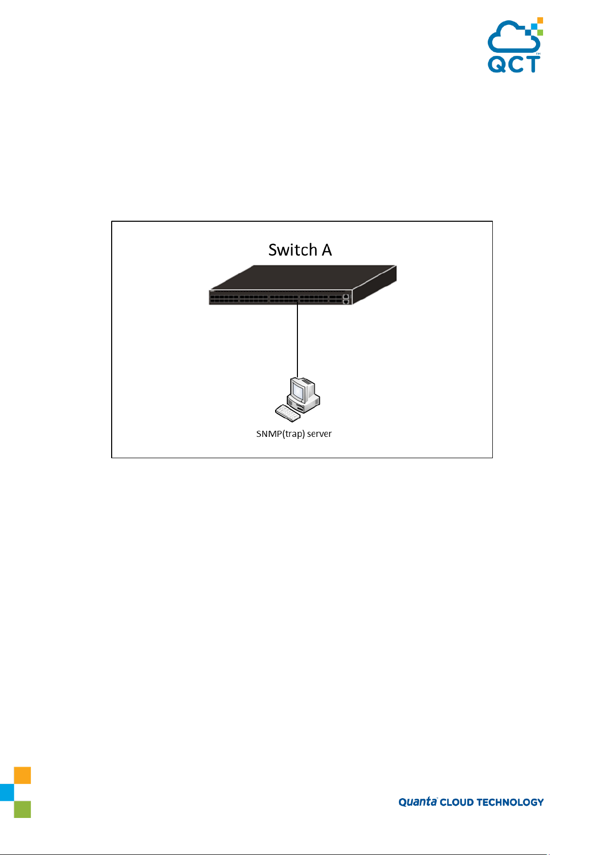
2.4.2.1. SNMPv3
SNMP version 3 (SNMPv3) adds security and remote configuration enhancements to SNMP. QNOS has the
ability to configure SNMP server, users, and traps for SNMPv3. Any user can connect to the switch using the
SNMPv3 protocol, but for authentication and encryption, you need to configure a new user profile. To
configure a profile by using the CLI, see the SNMP section in the QNOS CLI Command Reference.
2.4.2.2. SNMP Configuration example
Figure 2-1: SNMP Configuration Topology
Snmp v1, v2c community and trap configuration example
1. Add new community testRO for read only and testRW for read-write.
(QCT) (Config)#snmp-server community testRO ro
(QCT) (Config)#snmp-server community testRW rw
2. Setup SNMP trap host IP address.
(QCT) (Config)#snmp-server host 172.16.1.100 traps version 1 testRO
(QCT) (Config)#snmp-server host 172.16.2.100 traps version 2 testRO
3. Verify the configuration.
(QCT) #show snmp
Community-String Community-Access View Name IP Address
------------------ ---------------- --------------- ----------------
private Read/Write Default All
public Read Only Default All
testRO Read Only Default All
52

testRW Read/Write Default All
Community-String Group Name IP Address
------------------ ---------------------------- ----------------
private DefaultWrite All
public DefaultRead All
testRO DefaultRead All
testRW DefaultWrite All
Traps are enabled.
Authentication trap is enabled.
Version 1,2 notifications
Target Address Type Community Version UDP Filter TO Retries
Port name Sec
--------------- ------- ------------------- ------- ------ -------- --- ------
172.16.1.100 Trap testRO 1 162
172.16.2.100 Trap testRO 2 162
Version 3 notifications
Target Address Type Username Security UDP Filter TO Retries
Level Port name Sec
---------------- ------- ----------------- -------- ------ -------- --- -------
System Contact:
System Location:
Snmp v3 configuration example
1. Configure a view and oid-tree included iso.
(QCT) (Config)#snmp-server view testVIEW iso included
2. Configure a group which use testVIEW for read, write and notify(trap).
(QCT) (Config)#snmp-server group testGROUP v3 noauth read testVIEW write testVIEW notify
testVIEW
3. Add a user named testUSER and assign to testGROUP.
(QCT) (Config)#snmp-server user testUSER testGROUP
4. Setup SNMPv3 trap host IP address.
53

(QCT) (Config)#snmp-server host 172.16.1.102 traps version 3 testUSER noauth
5. Verify the configuration.
(QCT) #show snmp views
Name OID Tree Type
--------------------------- ------------------------------ ----------
Default iso Included
Default snmpVacmMIB Excluded
Default usmUser Excluded
Default snmpCommunityTable Excluded
testVIEW iso Included
DefaultSuper iso Included
(QCT) #show snmp group
Name Context Security Views
Prefix Model Level Read Write Notify
------------------ ---------- ----- ------------- -------- -------- --------
testGROUP "" V3 NoAuth-NoPriv testVIEW testVIEW testVIEW
DefaultRead "" V1 NoAuth-NoPriv Default "" Default
DefaultRead "" V2 NoAuth-NoPriv Default "" Default
DefaultRead "" V3 NoAuth-NoPriv Default "" Default
DefaultRead "" V3 Auth-NoPriv Default "" Default
DefaultRead "" V3 Auth-Priv Default "" Default
DefaultSuper "" V1 NoAuth-NoPriv DefaultS DefaultS DefaultS
uper uper uper
DefaultSuper "" V2 NoAuth-NoPriv DefaultS DefaultS DefaultS
uper uper uper
DefaultSuper "" V3 NoAuth-NoPriv DefaultS DefaultS DefaultS
uper uper uper
DefaultWrite "" V1 NoAuth-NoPriv Default Default Default
DefaultWrite "" V2 NoAuth-NoPriv Default Default Default
DefaultWrite "" V3 NoAuth-NoPriv Default Default Default
DefaultWrite "" V3 Auth-NoPriv Default Default Default
DefaultWrite "" V3 Auth-Priv Default Default Default
54

(QCT) #show snmp user
Name Group Name Auth Priv
Meth Meth Remote Engine ID
----------------- -------------- ---- ---- -------------------------
testUSER testGROUP 80001c4c03000000000004
(QCT) #show snmp
Community-String Community-Access View Name IP Address
------------------ ---------------- ---------------- ----------------
private Read/Write Default All
public Read Only Default All
testRO Read Only Default All
testRW Read/Write Default All
Community-String Group Name IP Address
------------------ ------------------------------ ----------------
private DefaultWrite All
public DefaultRead All
testRO DefaultRead All
testRW DefaultWrite All
Traps are enabled.
Authentication trap is enabled.
Version 1,2 notifications
Target Address Type Community Version UDP Filter TO Retries
Port name Sec
--------------- ------- ------------------ ------ ------ -------- --- ------
172.16.1.100 Trap testRO 1 162
172.16.2.100 Trap testRO 2 162
55

Version 3 notifications
Target Address Type Username Security UDP Filter TO Retries
Level Port name Sec
--------------- ------- -------------- -------- ------ -------- --- -------
172.16.1.102 Trap testUSER NoAuth-N 162 15 3
System Contact:
System Location:
56

3. Configuring L2 Switching Features
3.1. VLANs
By default, all switchports on the switch are in the same broadcast domain. This means when one host
connected to the switch broadcasts traffic, every device connected to the switch receives that broadcast. All
ports in a broadcast domain also forward multicast and unknown unicast traffic to the connected host.
Large broadcast domains can result in network congestion, and end users might complain that the network is
slow. In addition to latency, large broadcast domains are a greater security risk since all hosts receive all
broadcasts.
Virtual Local Area Networks (VLANs) allow you to divide a broadcast domain into smaller, logical networks.
Like a bridge, a VLAN switch forwards traffic based on the Layer 2 header, which is fast, and like a router, it
partitions the network into logical segments, which provides better administration, security, and
management of multicast traffic.
Network administrators have many reasons for creating logical divisions, such as department or project
membership. Because VLANs enable logical groupings, members do not need to be physically connected to
the same switch or network segment. Some network administrators use VLANs to segregate traffic by type
so that the time-sensitive traffic, like voice traffic, has priority over other traffic, such as data.
Administrators also use VLANs to protect network resources. Traffic sent by authenticated clients might be
assigned to one VLAN, while traffic sent from unauthenticated clients might be assigned to a different VLAN
that allows limited network access.
When one host in a VLAN sends a broadcast, the switch forwards traffic only to other members of that
VLAN. For traffic to go from a host in one VLAN to a host in a different VLAN, the traffic must be forwarded
by a layer 3 device, such as a router. VLANs work across multiple switches, so there is no requirement for the
hosts to be located near each other to participate in the same VLAN.
Note: QNOS software supports VLAN routing. When you configure VLAN routing, the switch acts as a
layer 3 device and can forward traffic between VLANs. For more information, see “VLAN Routing”.
Each VLAN has a unique number, called the VLAN ID. The QNOS supports a configurable VLAN ID range of 2–
4093. A VLAN with VLAN ID 1 is configured on the switch by default. You can associate a name with the VLAN
ID. In a tagged frame, the VLAN is identified by the VLAN ID in the tag. In an
is the Port VLAN ID (PVID) specified for the port that received the frame. For information about tagged and
untagged frames, see “VLAN Tagging”.
QNOS supports adding individual ports and Port-channels as VLAN members.
Figure 1 shows an example of a network with three VLANs that are department-based. The file server and
end stations for the department are all members of the same VLAN.
untagged
frame, the VLAN identifier
57
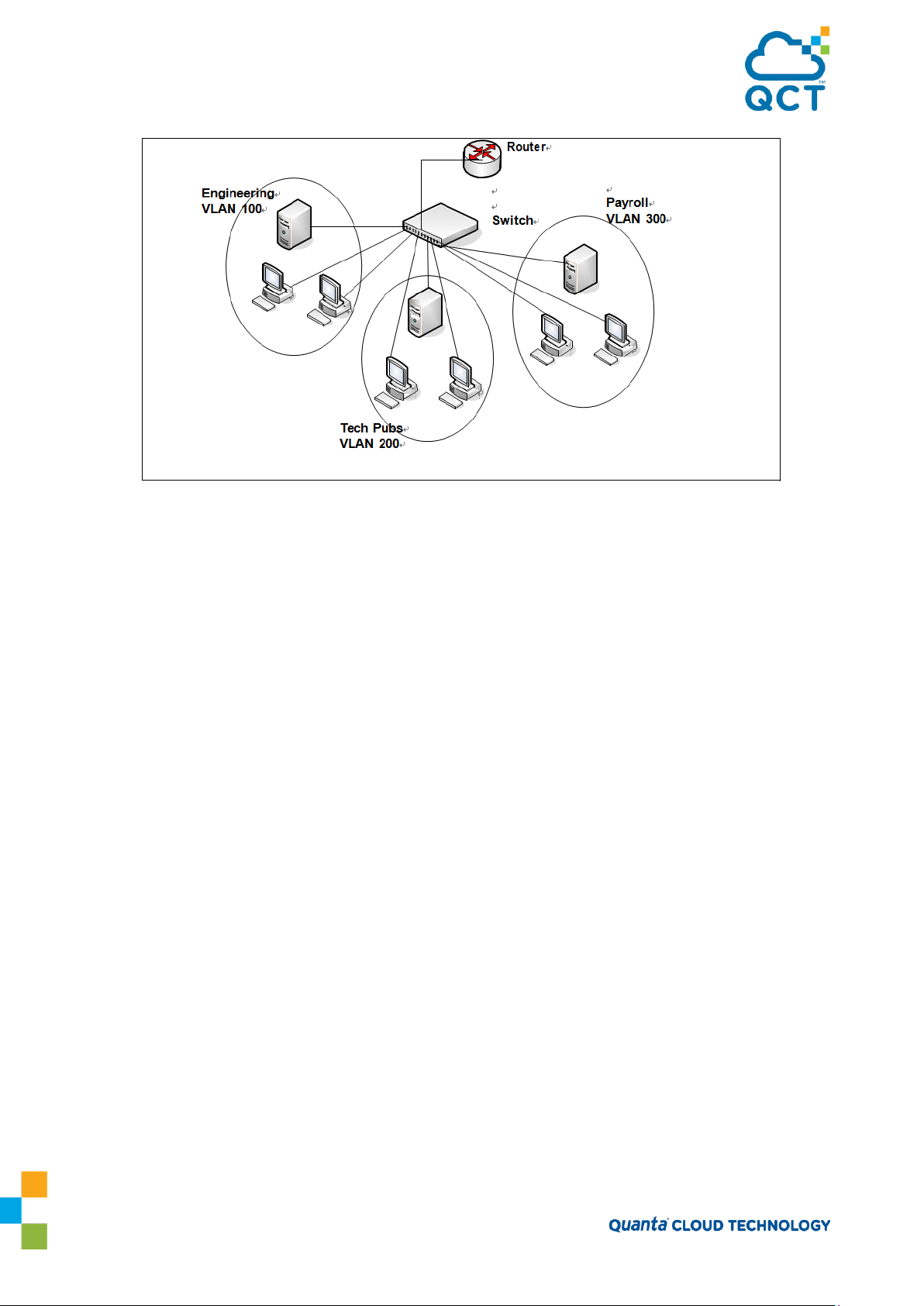
Figure 3-1: Simple VLAN Topology
In this example, each port is manually configured so that the end station attached to the port is a member of
the VLAN configured for the port. The VLAN membership for this network is port-based or static.
3.1.1. VLAN Tagging
QNOS supports IEEE 802.1Q tagging. Ethernet frames on a tagged VLAN have a 4-byte VLAN tag in the header.
VLAN tagging is required when a VLAN spans multiple switches, which is why trunk ports transmit and
receive only tagged frames.
Tagging may be required when a single port supports multiple devices that are members of different VLANs.
For example, a single port might be connected to an IP phone, a PC, and a printer (the PC and printer are
connected via ports on the IP phone). IP phones are typically configured to use a tagged VLAN for voice
traffic, while the PC and printers typically use the untagged VLAN.
When a port is added to a VLAN as an untagged member, untagged packets entering the switch are tagged
with the PVID (also called the native VLAN) of the port. If the port is added to a VLAN as an untagged
member, the port does not add a tag to a packet in that VLAN when it exits the port. Configuring the PVID for
an interface is useful when untagged and tagged packets will be sent and received on that port and a device
connected to the interface does not support VLAN tagging.
When ingress filtering is on, the frame is dropped if the port is not a member of the VLAN identified by the
VLAN ID in the tag. If ingress filtering is off, all tagged frames are forwarded. The port decides whether to
forward or drop the frame when the port receives the frame.
3.1.2. Double-VLAN Tagging
For trunk ports, which are ports that connect one switch to another switch, QNOS software supports
double- VLAN tagging. This feature allows service providers to create Virtual Metropolitan Area Networks
(VMANs). With double-VLAN tagging, service providers can pass VLAN traffic from one customer domain to
another through a metro core in a simple and cost-effective manner. By using an additional tag on the traffic,
58

the switch can differentiate between customers in the MAN while preserving an individual customer’s VLAN
identification when the traffic enters the customer’s 802.1Q domain.
With the introduction of this second tag, customers are no longer required to divide the 4-byte VLAN ID
space to send traffic on a
Ethernet-based
MAN. In short, every frame that is transmitted from an interface has
a double- VLAN tag attached, while every packet that is received from an interface has a tag removed (if one
or more tags are present).
In Figure 2, two customers share the same metro core. The service provider assigns each customer a unique
ID so that the provider can distinguish between the two customers and apply different rules to each. When
the configurable EtherType is assigned to something different than the 802.1Q (0x8100) EtherType, it allows
the traffic to have added security from
misconfiguration
while exiting the metro core. For example, if the edge
device on the other side of the metro core is not stripping the second tag, the packet would never be
classified as a 802.1Q tag, so the packet would be dropped rather than forwarded in the incorrect VLAN.
Figure 3-2: Double VLAN Tagging Network Example
3.1.3. Default VLAN Behavior
One VLAN exists on the switch by default. The VLAN ID is 1, and all ports are included in the VLAN as access
ports, which are untagged. This means when a device connects to any port on the switch, the port forwards
the packets without inserting a VLAN tag. If a device sends a tagged frame to a port, the frame is dropped.
Since all ports are members of this VLAN, all ports are in the same broadcast domain and receive all
broadcast and multicast traffic received on any port.
When you add a new VLAN to the VLAN database, no ports are members. The configurable VLAN range is 2–
4093. VLANs 4094 and 4095 are reserved.
Table 1 shows the default values or maximum values for VLAN features.
59

Table 3-1: VLAN default and maximum values
3.1.4. VLAN Configuration Example
A network administrator wants to create the VLANs in Table 2:
Table 3-2: Example VLAN
Figure 3 shows the network topology for this example. As the figure shows, there are two switches, two file
servers, and many hosts. One switch has an uplink port that connects it to a layer 3 device and the rest of the
corporate network.
60

Figure 3-3: Network Topology for VLAN Configuration
The network in Figure 3 has the following characteristics:
• Each connection to a host represents multiple ports and hosts.
• The Payroll and File servers are connected to the switches through a Port-channel.
• Some of the Marketing hosts connect to Switch 1, and some connect to Switch 2.
• The Engineering and Marketing departments share the same file server.
• Because security is a concern for the Payroll VLAN, the ports and Port-channel that are members of this
VLAN will accept and transmit only traffic tagged with VLAN 300.
Table 3 shows the port assignments on the switches.
Table 3-3: Switch Port Configuration
61

3.1.4.1. Configuring the VLANs and Ports on Switch 1
Use the following steps to configure the VLANs and ports on Switch 1. None of the hosts that connect to
Switch
1 use the Engineering VLAN (VLAN 100), so it is not necessary to create it on that switch. To configure Switch
1:
1. Create VLANs 200 (Marketing), 300 (Payroll), and associate the VLAN ID with the appropriate name.
(QCT) (Config)#vlan database
(QCT) (Vlan)#vlan 200,300
(QCT) (Vlan)#vlan name 200 Marketing (QCT) (Vlan)#vlan name 300 Payroll
(QCT) (Vlan)#exit
2. Assign ports 16–20 to the Marketing VLAN.
(QCT) #configure
(QCT) (Config)#interface range 0/16-0/20
(QCT) (Interface 0/16-0/20)#switchport allowed vlan add 200
(QCT) (Interface 0/16-0/20)#switchport native vlan 200
(QCT) (Interface 0/16-0/20)#exit
3. Assign ports 2–15 to the Payroll VLAN
(QCT) (Config)#interface range 0/2-0/15
(QCT) (Interface 0/2-0/15)#switchport allowed vlan add 300
(QCT) (Interface 0/2-0/15)#switchport native vlan 300
(QCT) (Interface 0/2-0/15)#exit
4. Assign Port-channel1 to the Payroll VLAN and configure the frames to always be transmitted tagged with
a PVID of 300.
(QCT) (Config)#interface port-channel 1
(QCT) (if-port-channel ch1)#switchport allowed vlan add tagged 300
(QCT) (if-port-channel ch1)#switchport native vlan 300
(QCT) (if-port-channel ch1)#exit
5. Configure port 1 as a trunk port and add VLAN 200 and VLAN 300 as members. Trunk ports accept and
transmits tagged frames only and have ingress filtering enabled.
(QCT) (Config)#interface 0/1
(QCT) (Interface 0/1)#switchport acceptable-frame-types tagged
(QCT) (Interface 0/1)#switchport allowed vlan add tagged 200,300
(QCT) (Interface 0/1)#switchport ingress-filtering
(QCT) (Interface 0/1)#exit
(QCT) (Config)#exit
62

Interface
Current
Configured
Tagging
----------
--------
-----------
--------
0/1 Include
Include
Tagged
0/2 Include
Include
Untagged
0/3 Include
Include
Untagged
0/4 Include
Include
Untagged
0/5 Include
Include
Untagged
6. To save the configuration so that it persists across a system reset, use the following command:
(QCT) #copy running-config startup-config
7. View the VLAN settings.
(QCT) #show vlan
VLAN ID VLAN Name VLAN Type Interface(s)
------- -------------------------------- ---------- -------------------------
1 default Default 0/1,0/2,0/3,0/4,0/5,0/6,
0/7,0/8,0/9,0/10,0/11,
0/12,0/13,0/14,0/15,0/16,
...
200 Marketing Static 0/1,0/16,0/17,0/18,0/19,
0/20
300 Payroll Static 0/1,0/2,0/3,0/4,0/5,0/6,
0/7,0/8,0/9,0/10,0/11,
0/12,0/13,0/14,0/15,ch1
(QCT) #show vlan id 300
VLAN ID: 300
VLAN Name: Payroll
VLAN Type: Static
--More-- or (q)uit
8. View the VLAN information for a
(QCT) #show interface switchport 0/1
port.
Interface...................................... 0/1
Native VLAN.................................... 1
Mode........................................... General
Ingress Filtering.............................. Enable
Acceptable Frame Type.......................... VLAN Only
63

Interface is member in:
VLAN ID VLAN Name VLAN Type Egress rule
------- -------------------------------- ----------------- -----------
1 default Default Untagged
200 Marketing Static Tagged
300 Payroll Static Tagged
3.1.4.2. Configuring the VLANs and Ports on Switch 2
Use the following steps to configure the VLANs and ports on Switch 2. Many of the procedures in this
section are the same as procedures used to configure Switch 1. For more information about specific
procedures, see the details and figures in the previous section.
To configure Switch 2:
1. Create the Engineering, Marketing, and Payroll VLANs.
Although the Payroll hosts do not connect to this switch, traffic from the Payroll department must use Switch
2 to reach the rest of the network and Internet through the uplink port. For that reason, Switch 2 must be
aware of VLAN 300 so that traffic is not rejected by the trunk port.
2. Configure ports 2-10 to participate in VLAN 200.
3. Configure ports 11–30 to participate in VLAN 100.
4. Configure Port-channel 1 to participate in VLAN 100 and VLAN 200.
5. Configure port 1 and Port-channel 2 as participants in ports and add VLAN 100, VLAN 200, and VLAN 300
that accept and transit tagged frames only.
6. Enable ingress filtering on port 1 and Port-channel 2.
7. If desired, copy the running configuration to the startup configuration.
8. View VLAN information for the switch and ports.
3.2. Switchport Modes
You can configure each port on an QNOS switch to be in one of the following modes:
•
Access —
Access ports are intended to connect end-stations to the system, especially when the endstations are incapable of generating VLAN tags. Access ports support a single VLAN (the PVID). Packets
received untagged are processed as if they are tagged with the access port PVID. Packets received that are
tagged with the PVID are also processed. Packets received that are tagged with a VLAN other than the PVID
64

are dropped. If the VLAN associated with an access port is deleted, the PVID of the access port is set to VLAN
1. VLAN 1 may not be deleted.
•
Trunk —
Trunk-mode ports are intended for switch-to-switch links. Trunk ports can receive both tagged
and untagged packets. Tagged packets received on a trunk port are forwarded on the VLAN contained in the
tag if the trunk port is a member of the VLAN. Untagged packets received on a trunk port are forwarded on
the native VLAN. Packets received on another interface belonging to the native VLAN are transmitted
untagged on a trunk port.
•
General —
General ports can act like access or trunk ports or a hybrid of both. VLAN membership rules
that apply to a port are based on the switchport mode configured for the port.
Table 4 shows the behavior of the three switchport modes.
Table 3-4: Switchport Mode Behavior
When a port is in General mode (by default all interfaces are in general mode), all VLAN features are
configurable. When ingress filtering is on, the frame is dropped if the port is not a member of the VLAN
identified by the VLAN ID in the tag. If ingress filtering is off, all tagged frames are forwarded. The port
decides whether to forward or drop the frame when the port receives the frame.
The following example configures a port in Access mode with a single VLAN membership in VLAN 10:
(QCT) #config
(QCT) (Config)#interface 0/5
(QCT) (Interface 0/5)#switchport mode access
(QCT) (Interface 0/5)#switchport access vlan 10
(QCT) (Interface 0/5)#exit
The following example configures a port in Trunk mode. The switchport trunk allowed vlan command with
the add keyword adds the list of VLANs that can receive and send traffic on the interface in tagged format
when in trunking mode. Alternatively, the all keyword can be used to specify membership in all VLANs, the
remove keyword can be used to remove membership. If this command is omitted, the port is a member of all
configured VLANs. The native VLAN specifies the VLAN on which the port forwards untagged packets it
receives.
(QCT) #config
(QCT) (Config)#interface 0/8
(QCT) (Interface 0/8)#switchport mode trunk
(QCT) (Interface 0/8)#switchport trunk allowed vlan add 10,20,30
(QCT) (Interface 0/8)#switchport trunk native vlan 100
(QCT) (Interface 0/8)#exit
65

The General mode port can then be configured as a tagged or untagged member of any VLAN, as shown in
“VLAN Configuration Example”.
3.3. Port-channels – Operation and Configuration
Port-channel allows one or more full-duplex (FDX) Ethernet links of the same speed to be aggregated
together to form a Port-channel. This allows the switch to treat the Port-channel as if it is a single link. The
primary purpose of Port-channels is to increase the overall bandwidth between two switches. This is
accomplished by effectively
between the two switches. Port-channels also provide redundancy. If a link fails, traffic is automatically
redistributed across the remaining links.
QNOS software supports industry-standard Port-channels that adhere to the IEEE 802.3ad specification. Both
static and dynamic Port-channels are supported. Each Port-channel can have a maximum of 32 ports as
members (as long as the platform can support it). You can configure Port-channels until all switch ports are
assigned to a Port-channel.
Figure 4 shows an example of a switch in the wiring closet connected to a switch in the data center by a
Port-channel that consists of four physical 10 Gbps links. The Port-channel provides full-duplex bandwidth
of 40 Gbps between the two switches.
aggregating
multiple ports together that act as a single, logical
connection
Figure 3-4: Port-channel Configuration
3.3.1. Static and Dynamic Port-channel
Port-channel can be configured as either dynamic or static. Dynamic configuration is supported using the
IEEE 802.3ad standard, which is known as Link Aggregation Control Protocol (LACP). Static configuration is
used when connecting the switch to an external Gigabit Ethernet switch that does not support LACP.
One advantage of LACP is that the protocol enables the switch to confirm that the external switch is also
configured for Port-channel. When using static configuration, a cabling or
local switch or the external switch could go
undetected
and thus cause
configuration
undesirable
mistake involving the
network
behavior.
Both
static and dynamic Port-channels (via LACP) can detect physical link failures within the Port-channel and
continue forwarding traffic through the other connected links within that same Port-channel. LACP can also
detect switch or port failures that do not result in loss of link. This provides a more resilient Port-channel.
Best practices suggest using dynamic link aggregation instead of static link aggregation. When a port is
added to a Port-channel as a static member, it neither transmits nor receives LACP PDUs.
3.3.2. Port-channel Hashing
66

QNOS software support configuration of hashing algorithms for each Port-channel interface. The hashing
algorithm is used to distribute traffic load among the physical ports of the Port-channel while preserving the
per-flow packet order.
The hashing algorithm uses various packet attributes to determine the outgoing physical port. The switch
supports the following set of packet attributes to be used for hash computation:
Source MAC, VLAN, EtherType, and incoming port.
Destination MAC, VLAN, EtherType, and incoming port.
Source IP and Source TCP/UDP port numbers.
Destination IP and Destination TCP/UDP port numbers.
Source/Destination MAC, VLAN, EtherType, and incoming port.
Source/Destination IP and Source/Destination TCP/UDP port numbers.
Enhanced hashing mode
Enhanced hashing mode has following advantages:
MODULO-N operation based on the number of ports in the Port-channel.
Packet attributes selection based on the packet type. For L2 packets, Source and Destination
MAC
address are used for hash computation. For IP packets, Source IP, Destination IP address,
TCP/UDP ports are used.
Non-Unicast traffic and Unicast traffic is hashed using a common hash algorithm.
Excellent load balancing performance.
3.3.2.1. Resilient Hasing
Resilient Hashing (RH) is a feature on QNOS switches that introduces an extra level of indirection between
the hash value and the selected output port for a layer-2 Port-channel or a layer-3 ECMP route. In a typical
non-RH configuration, the output port can change for all flows when the number of ports changes, even if
the flow was on a port that was not affected. This can cause degraded performance due to frame reordering.
With RH, the hash value is used to index into a table of ports. If a port goes down, then only the entries that
use that port are rewritten. Other ports are left untouched and, therefore, do not suffer degraded
performance.
Resilient hashing is globally enabled on switch ports by default. It can be globally enabled (or disabled) in
Global Config mode using the (no) port-channel
resilient-hashing command for ECMP routes. The new setting takes effect after a system reboot.
resilient-hashing
command for Port-channels or the (no) ip
3.3.2.2. Hash Prediction with ECMP and Port-channel
The Hash Prediction feature provides a utility to predict how packets will be forwarded over a Port-channel or
to the next- hop device when Equal-Cost Multipath (ECMP) is the destination. Given the Port-channel
method, ingress physical port, and values of various packet fields, the utility predicts an egress physical port
for the packet.
67

1
ch1 1
Down
Disabled Dynamic 0/1,0/2,
0/3,0/6,
0/7
2 ch2 1 Down Disabled Static
3 ch3 1 Down Disabled Static
4 ch4 1 Down Disabled Static
5 ch5 1 Down Disabled Static
An ECMP group is identified by the IP address of one of its members. By entering the IP address in the form
<prefix/prefix-length>, the utility predicts the packet's physical egress port based on the destination ECMP
group. To predict the an egress physical port when the egress objects are VLAN routing interfaces with Portchannel or port interfaces as members of the VLANs, the utility requires the PVID to be configured on the
interfaces and the next hops to be fully installed in hardware.
If an ECMP group is comprised of VLAN routing interfaces and each VLAN has a Port-channel that contains
multiple ports, the utility requires the PVID to be configured on the Port-channels. In this configuration, the
utility first predicts which VLAN routing interface the packet is forwarded to and finds the Port-channel by
matching the VLAN ID of the VLAN routing interface to the PVID of the Port-channel. Then, it predicts which
physical port in the Port-channel the packet is forwarded to.
To make correct prediction when Port-channels are used as egress interfaces, the utility requires the
enhanced hashing mode to be set on the Port-channels.
Hash prediction is supported only for unicast packets on QNOS-based platforms.
3.3.3. Port-channel Interface Overview
The show interface port-channel brief command provides summary information about all Port-channels
available on the system. In the following output, Port-channel 3/1 has been configured as a dynamic Portchannel with five member ports. No other Port-channels have been configured.
(QCT) #show interface port-channel brief
Channel Port-Channel Min Link State Trap Type Mbr Ports Active Ports
ID Name Flag
--------- ------------- --- ---------- -------- ------- --------- ------------
3.3.4. Port-channel Interaction with Other Features
From a system perspective, a Port-channel is treated just as a physical port, with the same configuration
parameters for administrative enable/disable, spanning tree port priority, path cost as may be for any other
physical port.
3.3.4.1. VLAN
When members are added to a Port-channel, they are removed from all existing VLAN membership. When
members are removed from a Port-channel they are added back to the VLANs that they were previously
members of as per the configuration file. Note that a port’s VLAN membership can still be configured when
68

it's a member of a Port-channel. However this configuration is only actually applied when the port leaves
the Port-channel.
The Port-channel interface can be a member of a VLAN complying with IEEE 802.1Q.
3.3.4.2. STP
Spanning tree does not maintain state for members of a Port-channel, but the Spanning Tree does maintain
state for the Port-channel interface. As far as STP is concerned, members of a Port-channel do not exist.
(Internally, the STP state of the Port-channel interface is replicated for the member links.)
When members are deleted from a Port-channel they become normal links, and spanning tree maintains
their state information.
3.3.4.3. Statistics
Statistics are maintained for all Port-channel interfaces as they are done for the physical ports, besides
statistics maintained for individual members as per the 802.3ad MIB statistics.
3.3.5. Port-channel Configuration Guidelines
Ports to be aggregated must be configured so that they are compatible with the Port-channel feature and
with the partner switch to which they connect.
Ports to be added to a Port-channel must meet the following requirements:
Interface must be a physical Ethernet link.
Each member of the Port-channel must be running at the same speed and must be in full
duplex mode.
The port cannot be a mirrored port
The following are the interface restrictions
The configured speed of a Port-channel member cannot be changed.
An interface can be a member of only one Port-channel.
3.3.5.1. Port-channel Configuration Examples
This section contains the following examples:
Configuring Dynamic Port-channels
Configuring Static Port-channels
Note: The examples in this section show the configuration of only one switch. Because Port-channels
involve physical links between two switches, the Port-channel settings and member ports must be
configured on both switches.
69

3.3.5.2. Configuration Dynamic Port-channels
The commands in this example show how to configure a dynamic Port-channel on a switch. The Portchannel number is 1 (ch1), and the member ports are 1, 2, 3, 6, and 7.
To configure the switch:
1. Enter interface configuration mode for the ports that are to be configured as Port-channel members.
(QCT) #config
(QCT) (Config)#interface range 0/1-0/3,0/6-0/7
2. Add the ports to Port-channel 1 with LACP.
(QCT) (Interface 0/1-0/3,0/6-0/7)#channel-group 1 mode active
(QCT) (Interface 0/1-0/3,0/6-0/7)#exit
3. View information about Port-channel 1.
(QCT) #show interface port-channel 1
Port Channel ID................................ 1
Channel Name................................... ch1
Link State..................................... Down
Admin Mode..................................... Enabled
Link Trap Mode................................. Enabled
STP Mode....................................... Enabled
Type........................................... Dynamic
Port-channel Min-links......................... 1
Load Balance Option............................ 3
(Src/Dest MAC, VLAN, EType, incoming port)
LACP Min. Links................................ 1
Mbr Device/ Port Port
Ports Timeout Speed Active
------ ------------- --------- -------
0/1 actor/long 10G Full False
partner/long
0/2 actor/long 10G Full False
partner/long
0/3 actor/long 10G Full False
partner/long
0/6 actor/long 10G Full False
partner/long
0/7 actor/long 10G Full False
70

partner/long
3.3.5.3. Configuration Static Port-channels
The commands in this example show how to configure a static Port-channel on a switch. The Port-channel
number is 3 (ch3), and the member ports are 10, 11, 14, and 17. To configure the switch:
1. Enter interface configuration mode for the ports that are to be configured as Port-channel members.
(QCT) (Config)#interface range 0/10-0/12,0/14,0/17
2. Add the ports to Port-channel 3 without LACP.
(QCT) (Interface 0/10-0/12,0/14,0/17)#channel-group 3 mode on
(QCT) (Interface 0/10-0/12,0/14,0/17)#exit
(QCT) (Config)#exit
3. View information about Port-channel 3.
(QCT) #show interface port-channel 3
Port Channel ID................................ 3
Channel Name................................... ch3
Link State..................................... Down
Admin Mode..................................... Enabled
Link Trap Mode................................. Enabled
STP Mode....................................... Enabled
Type........................................... Static
Port-channel Min-links......................... 1
Load Balance Option............................ 3
(Src/Dest MAC, VLAN, EType, incoming port)
LACP Min. Links................................ 1
Mbr Device/ Port Port
Ports Timeout Speed Active
------ ------------- --------- -------
0/10 actor/long 10G Full False
partner/long
0/11 actor/long 10G Full False
partner/long
0/12 actor/long 10G Full False
partner/long
0/14 actor/long 10G Full False
partner/long
71

0/17 actor/long 10G Full False
partner/long
3.4. LACP Fallback Configuration
3.4.1. Configuring Dynamic Port-channels
The commands in this example show how to configure a dynamic Port-channel on a switch. The Portchannel number is 1 (ch1), and the member ports are 1, 2, 3, 6, and 7.
To configure the switch:
1. Enter interface configuration mode for the ports that are to be configured as Port-channel members.
(QCT) #config
(QCT) (Config)#interface range 0/1-0/3,0/6-0/7
2. Add the ports to Port-channel 1 with LACP.
(QCT) (Interface 0/1-0/3,0/6-0/7)#channel-group 1 mode active
(QCT) (Interface 0/1-0/3,0/6-0/7)#exit
3. View information about Port-channel 1.
(QCT) #show interface port-channel 1
Port Channel ID................................ 1
Channel Name................................... ch1
Link State..................................... Down
Admin Mode..................................... Enabled
Link Trap Mode................................. Enabled
STP Mode....................................... Enabled
Type........................................... Dynamic
Port-channel Min-links......................... 1
Load Balance Option............................ 3
(Src/Dest MAC, VLAN, EType, incoming port)
LACP Min. Links................................ 1
Mbr Device/ Port Port
Ports Timeout Speed Active
------ ------------- --------- -------
0/1 actor/long 10G Full False
partner/long
0/2 actor/long 10G Full False
72

partner/long
0/3 actor/long 10G Full False
partner/long
0/6 actor/long 10G Full False
partner/long
0/7 actor/long 10G Full False
partner/long
4. (Optional) Enable LACP Fallback feature which enabled the switch keep one LACP member port link up even
if LACP port doesn’t receive the LACP message from the other side.
(QCT) #(if-port-channel ch1)#lacp fallback
5. (Optional) Verify LACP Fallback feature of Port-channel 1.
(QCT) #show interface port-channel 1
Port Channel ID................................ 1
Channel Name................................... ch1
Link State..................................... Down
Admin Mode..................................... Enabled
Link Trap Mode................................. Disabled
STP Mode....................................... Enabled
Type........................................... Dynamic
Port-channel Min-links......................... 1
Load Balance Option............................ 3
(Src/Dest MAC, VLAN, EType, incoming port)
LACP Fallback Mode............................. Enabled
LACP Fallback Timeout.......................... 5
LACP Min. Links................................ 1
Mbr Device/ Port Port Fallback
Ports Timeout Speed Active
------ ------------- --------- ------- ---------
0/1 actor/long 10G Full False None
partner/long
0/2 actor/long 10G Full False None
3.4.2. Configuring Static Port-channels
The commands in this example show how to configure a static Port-channel on a switch. The Port-channel
number is 3 (ch3), and the member ports are 10, 11, 14, and 17. To configure the switch:
73

1. Enter interface configuration mode for the ports that are to be configured as Port-channel members.
(QCT) (Config)#interface range 0/10-0/12,0/14,0/17
2. Add the ports to Port-channel 3 without LACP.
(QCT) (Interface 0/10-0/12,0/14,0/17)#channel-group 3 mode on
(QCT) (Interface 0/10-0/12,0/14,0/17)#exit
(QCT) (Config)#exit
3. View information about Port-channel 3.
(QCT) #show interface port-channel 3
Port Channel ID................................ 3
Channel Name................................... ch3
Link State..................................... Down
Admin Mode..................................... Enabled
Link Trap Mode................................. Enabled
STP Mode....................................... Enabled
Type........................................... Static
Port-channel Min-links......................... 1
Load Balance Option............................ 3
(Src/Dest MAC, VLAN, EType, incoming port)
LACP Min. Links................................ 1
Mbr Device/ Port Port
Ports Timeout Speed Active
------ ------------- --------- -------
0/10 actor/long 10G Full False
partner/long
0/11 actor/long 10G Full False
partner/long
0/12 actor/long 10G Full False
partner/long
0/14 actor/long 10G Full False
partner/long
0/17 actor/long 10G Full False
partner/long
3.5. MLAG – Operation and Configuration
74

3.5.1. Overview
In a typical layer-2 network, the Spanning Tree Protocol (STP) is deployed to avoid packet storms due to
loops in the network. To perform this function, STP sets ports into either a forwarding state or a blocking
state. Ports in the blocking state do not carry traffic. In the case of a topology change, STP reconverges to a
new loop-free network and updates the port states. STP is relatively successful mitigating packet storms in
the network, but redundant links in the network are blocked from carrying traffic by the spanning tree
protocol.
In some network deployments, redundant links between two switches are bundled together in a Portchannel and appear as a single link in the spanning tree topology. The advantage is that all Port-channel
member links can be in the forwarding state and a link failure can be recovered in
bandwidth on the redundant links to be utilized. However, Port-channels are limited to connecting multiple
links between two partner switches, which leaves the switch as a single point of failure in the topology.
QNOS MLAG extends the Port-channel bandwidth advantage across multiple QNOS switches connected to a
Port-channel partner device. The Port-channel partner device is oblivious to the fact that it is connected
over a Port-channel to two peer QNOS switches; instead, the two switches appear as a single switch to the
partner with a single MAC address. All links can carry data traffic across a physically diverse topology and in
the case of a link or switch failure, traffic can continue to flow with minimal disruption.
milliseconds.
This allows the
3.5.2. Deployment Scenarios
MLAG is intended to support higher bandwidth utilization in scenarios where a redundant layer-2 network is
desired. In such scenarios the effects of STP on link utilization are profound. Large percentages of links do not
carry data because they are blocked and only a single path through the network carries traffic.
Figure 3-5: STP Blocking
MLAG reduces some of the bandwidth shortcomings of STP in a layer-2 network. It provides a reduced
convergence period when a port-channel link goes down and provides more bandwidth because all links can
forward traffic. In the figure below, if SW1 and SW2 form a MLAG with SW3 and SW4, none of the links are
blocked, which means traffic can flow over both links from SW4 through to SW1 and SW2 over both links
from SW1 and SW2 to SW3.
75

3.5.2.1. Definitions
Figure 3-6: MLAG in a Layer-2 Network
Refer to Figure 7 for the definitions that follow.
Figure 3-7: MLAG Components
MLAG switches: MLAG-aware switches running QNOS switch firmware. No more than two MLAG aware
switches can pair to form one end of the Port-channel. Stacked switches do not support MLAGs. In the above
figure, SW1 and SW2 are MLAG peer switches. These two switches form a single logical end point for the
MLAG from the perspective of switch A.
MLAG interfaces: MLAG functionality is a property of Port-channels. Port-channels configured as MLAGs are
called MLAG interfaces. Administrators can configure multiple instances of MLAG interfaces on the peer
76

MLAG switches. Port-channel limitations and capabilities such as min-links and maximum number of ports
supported per Port-channel also apply to MLAG interfaces.
MLAG member ports: Ports on the peer MLAG switches that are part of the MLAG interface (P1 on SW1 and
S1 on SW2).
MLAG peer-link: A link between the two MLAG peer switches (ports P2,P3,S2,S3). Only one peer-link can be
configured per device. The peer-link is crucial for the operation of the MLAG component. A Port-channel
must be configured as the peer-link. All VLANs configured on MLAG interfaces must be configured on the
peer-link as well.
MLAG Dual Control Plane Detection link: A virtual link that is used to advertise the Dual Control Plane
Detection Protocol (DCPDP) packets between the two MLAG switches (ports P4, S4). DCPDP is optional but
should be used with caution. The protocol is used as a secondary means of detecting the presence of the
peer switch in the network. The DCPDP protocol must not be configured on MLAG interfaces.
3.5.2.2. Configuration Consistency
MLAG is operational only if the MLAG domain ID, MLAG system MAC address, and MLAG system priority
are the same on both the MLAG peer switches.
Note: Configuring a MLAG domain ID is mandatory; the MLAG system MAC address and MLAG system
priority are optional (these values are auto generated if not configured)
The administrator must ensure that the neighboring devices connected to MLAG switches perceive the two
switches as a single spanning tree and Link Aggregation Control Protocol (LACP) entity. To achieve this end,
the following configuration settings must be identical for MLAG links on the MLAG peer switches:
1. Port-channel
Hashing mode
Minimum links
Static/dynamic Port-channel
LACP parameters
– Actor parameters
– Admin key
– Collector max-delay
– Partner parameters
2. STP
The default STP mode for QNOS switches is MSTP. The following STP configuration parameters must be the
identical on both MLAG peers.
Spanning-tree version (RSTP or MSTP)
Bpdufilter
77

Bpduflood
Auto-edge
TCN-guard
Cost
Edgeport
STP Version
STP MST VLAN configuration
STP MST instance configuration (MST instance ID/port priority/port cost/mode)
Root guard
Loop guard
3. Port-channel interface
The following Port-channel attributes must be identical for MLAG Port-channels:
Port-channel mode
Link speed
Duplex mode
MTU
Bandwidth
VLAN configuration
The administrator should also ensure that the following are identical before enabling MLAG:
FDB entry aging timers
Static MAC entries.
ACL configuration
4. Interface Configuration
PFC configuration
CoS queue assignments
5. VLAN configuration
MLAG VLANs must span the MLAG topology and be configured on both MLAG peers. This
means that every MLAG VLAN must connect to two partner Port-channels.
VLAN termination of a MLAG VLAN on a MLAG peer is not supported.
6. Switch firmware versions
Except during firmware upgrade, the peer switch firmware versions must be identical, as subtle differences
between versions may cause instability.
The administrator must ensure that the above configuration items are configured identically on the MLAG
interfaces on both of the MLAG peers before enabling the MLAG feature. If the configuration settings are
78

not in sync, the MLAG behavior is undefined. Once the above configuration is in place and consistent, the two
switches will form a MLAG that operates in the desired manner. The MLAG may form even if the
configuration is not consistent, however, it may not operate consistently in all situations.
3.5.3. MLAG Fast Failover
Prior to QNOS version, when the primary switch fails, secondary switch restarts the LACP protocol on its
MLAG member ports. STP is also restarted on secondary device’s MLAG member ports. Until the LACP and
STP reconverges, the partner device is disconnected from the MLAG domain.
With fast failover support, neither LACP reconvergence nor STP reconvergence occurs, and minimal traffic
loss is observed when primary device fails. During the failover, traffic that is being forwarded using the links
connected to primary device will failover to links connected to the secondary device. The traffic disruption
is limited to the time required for the partner devices dual-attached to the MLAG domain to detect the link
down(links connected to primary device) and redistribute the traffic using the links connected to the
secondary device.
3.5.4. MLAG Configuration
Refer to Figure 8 for a visual overview of the MLAG configuration steps.
Figure 3-8: MLAG Configuration Diagram
To configure MLAG:
1. Enter VLAN data base mode and create the MLAG VLANs.
(QCT) (Config)#vlan database
(QCT) (Vlan)#vlan 1-100
2. Enable the MLAG feature.
79

(QCT) #config
(QCT) (Config)#mlag
3. Create the MLAG domain ID. The domain ID configured on both the MLAG peer switches should be same.
In a two-tier MLAG topology, each pair should have different domain ID.
(QCT) (Config)#mlag domain 1
4. Configure the MLAG system MAC address and/or MLAG system priority (optional).
(QCT) (Config)#mlag system-mac C4:54:44:01:01:01
5. Enable the keepalive protocol.
(QCT) (Config)#mlag peer-keepalive enable
6. Configure the MLAG role priority (optional).
(QCT) (Config)#mlag role priority 10
7. Create Port-channel 1.
(QCT) (Config)#interface port-channel 1
(QCT) (if-port-channel ch1)#description "MLAG-Peer-Link"
8. Allow the Port-channel to participate in all VLANs and accept and send tagged frames only. This is similar
to configuring a port in trunk mode.
(QCT) (if-port-channel ch1)#switchport allowed vlan add tagged 1-99
(QCT) (if-port-channel ch1)#switchport acceptable-frame-types tagged
(QCT) (if-port-channel ch1)#mlag peer-link
(QCT) (if-port-channel ch1)#exit
9. Create the peer link.
(QCT) (Config)#interface range 0/1-0/2
(QCT) (Interface 0/1-0/2)#channel-group 1 mode active
(QCT) (Interface 0/1-0/2)#description "MLAG-Peer-Link"
10. Enable UDLD (if required).
(QCT) (Interface 0/1-0/2)#udld enable
(QCT) (Interface 0/1-0/2)#udld port aggressive
(QCT) (Interface 0/1-0/2)#exit
11. Configure Dual Control Plane detection Protocol Configuration (if required):
a. Configure a VLAN routing interface and assign a local IP address (independent form the peer address).
(QCT) (Config)#interface vlan
100
b. Configure the peer-switch IP address (the destination IP address). This command configures the IP
address of the peer MLAG switch. This configuration is used by the dual control plane detection protocol
(DCPDP) on the MLAG switches. The UDP port on which the MLAG switch listens to the DCPDP messages can
80

also be configured with this command. The configurable range for the UDP port 1 to 65535 (Default is
60000).
(QCT) (if-vlan100)#ip address 192.168.0.2 255.255.255.0
(QCT) (if-vlan100)#exit
c. Configure the keepalive source and destination IP address.
(QCT) #config
(QCT) (Config)#mlag peer-keepalive destination 192.168.0.1 source 192.168.0.2
d. Configure the DCPDP transmission interval and reception timeout values (optional).
(QCT) (Config)#mlag peer detection interval 600 timeout 2000
e. Enable Peer Detection mode. The mode starts running if MLAG is globally enabled.
(QCT) (Config)#mlag peer detection enable
12. Configure a Port-channel as MLAG interface. The configurable range for the MLAG ID is 1 to 63.
(QCT) (Config)#interface range 0/3-0/6
(QCT) (Interface 0/3-0/6)#channel-group 2 mode active
(QCT) (Interface 0/3-0/6)#exit
(QCT) (Config)#interface range 0/7-0/10
(QCT) (Interface 0/7-0/10)#channel-group 3 mode active
(QCT) (Interface 0/7-0/10)#exit
(QCT) (Config)#interface port-channel 2
(QCT) (if-port-channel ch2)#switchport allowed vlan add tagged 1-99
(QCT) (if-port-channel ch2)#switchport acceptable-frame-types tagged
(QCT) (if-port-channel ch2)#mlag 1
(QCT) (if-port-channel ch2)#exit
(QCT) (Config)#interface lag 3
(QCT) (if-port-channel ch3)#switchport allowed vlan add tagged 1-99
(QCT) (if-port-channel ch3)#switchport acceptable-frame-types tagged
(QCT) (if-port-channel ch3)#mlag 2
(QCT) (if-port-channel ch3)#exit
The administrator must ensure that the port channel configurations on both devices are in sync before
enabling MLAG. After the MLAG interfaces are enabled, the MLAG interfaces are operationally shut down.
The MLAG component exchanges information regarding the port members that constitute the Port-channel
on each device. Once this information is populated on both devices, the MLAG interfaces are operationally
up and traffic forwarding on MLAG interfaces is allowed. Port-channels must be configured on both devices
as MLAG interfaces for the MLAG interface to be enabled. Also, the port-channel-number: MLAG-Id pair
must be the same on both the primary and secondary devices.
Member ports can be added or removed from the MLAG interface. If a port is added as a port member to a
MLAG interface, the Primary allows the port member if the maximum criteria is satisfied. When a port
81

member is removed from the MLAG interface, the Primary decides if the minimum criteria is satisfied. If it
is not, it will shut down the MLAG interface on both the devices. Shutting down the MLAG interface on the
Secondary is not allowed. The MLAG interface can only be shut down on the Primary.
FDB entries learned on MLAG interfaces are synced between the two devices. In the case where all MLAG
member ports are UP, data traffic does not traverse the peer link.
3.6. Unidirectional Link Detection (UDLD)
The UDLD feature detects unidirectional links on physical ports. UDLD must be enabled on the both sides of
the link in order to detect a unidirectional link. The UDLD protocol operates by exchanging packets
containing information about neighboring devices.
The purpose of UDLD feature is to detect and avoid unidirectional links. A unidirectional link is a forwarding
anomaly in a Layer 2 communication channel in which a bidirectional link stops passing traffic in one
direction.
3.6.1. UDLD Modes
The UDLD supports two modes: normal and aggressive.
In normal mode, a port's state is classified as undetermined if an anomaly exists. An anomaly might be the
absence of its own information in received UDLD messages or the failure to receive UDLD messages. An
undetermined state has no effect on the operation of the port. The port is not disabled and continues
operating. When operating in UDLD normal mode, a port will be put into a disabled state (D-Disable) only in
the following situations:
The UDLD PDU received from a partner does not have its own details (echo).
When there is a loopback, and information sent out on a port is received back exactly as it
was sent.
When operating in UDLD aggressive mode, a port is put into a disabled state for the same reasons that it
occurs in normal mode. Additionally, a port in UDLD aggressive mode can be disabled if the port does not
receive any UDLD echo packets even after
established,
assumes that link has become unidirectional.
and packets suddenly stop coming from partner device, the UDLD aggressive-mode port
bidirectional connection
was
established.
If a
bidirectional
link is
3.6.2. UDLD and Port-channel Interfaces
UDLD is supported on individual physical ports that are members of a Port-channel. If any of the aggregated
links becomes unidirectional, UDLD detects it and disables the individual link, but not the entire Portchannel. This improves the fault tolerance of the Port-channel.
3.6.3. Configuring UDLD
A network administrator decides to use the UDLD feature while building a loop-free topology with the use
of STP. The administrator configures the ports on both side of the link to use UDLD in aggressive mode to
ensure that ports with unidirectional links will be shut down, and no loops will be introduced into topology.
82

Port
Admin Mode
UDLD Mode
UDLD Status
-----
----------
-----------
--------------
0/1 Disabled
Normal
Not Applicable
0/2 Enabled
Aggressive
Bidirectional
0/3 Disabled
Normal
Not Applicable
0/4 Disabled
Normal
Not Applicable
0/5 Enabled
Aggressive
Bidirectional
This example shows the steps to configure UDLD on Switch 1 only. The same configuration must be
performed on all ports that form partner links with the ports on Switch 1.
Figure 3-9: UDLD Configuration Example
To configure the ports on Switch 1:
1. Globally enable UDLD on the switch.
(QCT) #configure
(QCT) (Config)#udld enable
2. Enter interface configuration mode for the ports that are connected to other switches and enable UDLD
on the ports.
(QCT) (Config)#interface range 0/2,0/5,0/8
(QCT) (Interface 0/2,0/5,0/8)#udld enable
3. Configure the UDLD mode on the ports to be aggressive.
(QCT) (Interface 0/2,0/5,0/8)#udld port aggressive
(QCT) (Interface 0/2,0/5,0/8)#exit
(QCT) (Config)#exit
1. After configuring UDLD on Switch 2, Switch, 3, and Switch 4, view the UDLD status for the ports.
(QCT) #show udld all
83

0/6 Disabled
Normal
Not Applicable
0/7 Disabled
Normal
Not Applicable
0/8 Enabled
Aggressive
Bidirectional
0/9 Disabled
Normal
Not Applicable
--More-- or (q)uit
Note: If a port has become disabled by the UDLD feature and you want to re-enable the port, use the
reset
command in Privileged EXEC mode.
udld
3.7. Port Mirroring
Port mirroring is used to monitor the network traffic that a port sends and receives. The Port Mirroring
feature creates a copy of the traffic that the source port handles and sends it to a destination port. The
source port is the port that is being monitored. The destination port is monitoring the source port. The
destination port is where you would connect a network protocol analyzer to learn more about the traffic that
is handled by the source port.
A port monitoring session includes one or more source ports that mirror traffic to a single destination port.
QNOS software supports a single port monitoring session. Port-channels cannot be used as the source or
destination ports.
For each source port, you can specify whether to mirror ingress traffic (traffic the port receives, or RX),
egress traffic (traffic the port sends, or TX), or both ingress and egress traffic.
The packet that is copied to the destination port is in the same format as the original packet on the wire.
This means that if the mirror is copying a received packet, the copied packet is VLAN tagged or untagged as
it was received on the source port. If the mirror is copying a transmitted packet, the copied packet is VLAN
tagged or untagged as it is being transmitted on the source port.
After you configure the port mirroring session, you can enable or disable the administrative mode of the
session to start or stop the probe port from receiving mirrored traffic.
3.7.1. Configuring Port Mirroring
In this example, traffic from ports 1 and 4 is mirrored to probe port 10.
1. Configure the source ports. Traffic received and transmitted on by these ports will be mirrored.
(QCT) #configure
(QCT) (Config)#port-monitor session 1 source interface 0/1
2. Configure the destination (probe) port.
(QCT) (Config)#port-monitor session 1 destination interface 0/10
3. Enable port mirroring on the switch.
84

(QCT) (Config)#port-monitor session 1 mode
(QCT) (Config)#exit
4. View summary information about the port mirroring configuration.
(QCT) #show port-monitor session 1
Session Admin Probe Src Mirrored Ref. Src Dst Type IP MAC
ID Mode Port VLAN Port Port RVLAN RVLAN ACL ACL
------- ------- ------- ---- -------- ------- ----- ----- ---- ------- -------
1 Enable 0/10 0/1 Rx,Tx
0/4 Rx,Tx
3.7.2. Configuring RSPAN
This example mirrors traffic from port 6 on a source switch (SW1) to a probe port on a remote switch (port
12 on SW3). The mirrored traffic is carried in the RSPAN VLAN and VLAN 100, which traverses an
intermediate switch (SW2). The commands in this example show how to configure port mirroring on the
source, intermediate, and destination switches.
Figure 10 provides a visual overview of the RSPAN configuration example.
Figure 3-10: RSPAN Configuration Example
3.7.2.1. Configuration on the Source Switch (SW1)
To configure the source switch:
1. Access the VLAN configuration mode and create VLAN 100, which will be the RSPAN VLAN.
(QCT) #configure
85

(QCT) (Config)#vlan database
(QCT) (Vlan)#vlan 100 (QCT) (Vlan)#exit
2. Configure VLAN 100 as the RSPAN VLAN.
(QCT) #configure
(QCT) (Config)#vlan 100
(QCT) (Config)(vlan 100)#remote-span
(QCT) (Config)(vlan 100)#exit
3. Configure the RSPAN VLAN as the destination port and the reflector port as port 0/48.
(QCT) #configure
(QCT) (Config)#port-monitor session 1 destination remote vlan 100 reflector-port 0/48
4. Configure the source interface port as port 0/6.
(QCT) (Config)#port-monitor session 1 source interface 0/6
5. Enable the port mirroring session on the switch.
(QCT) (Config)#port-monitor session 1 mode
(QCT) #exit
3.7.2.2. Configuration on the Intermediate Switch (SW2)
To configure the intermediate switch:
1. Access the VLAN configuration mode and create VLAN 100.
(QCT) #configure
(QCT) (Config)#vlan database
(QCT) (Vlan)#vlan 100
(QCT) (Vlan)#exit
2. Enable RSPAN on vlan 100.
(QCT) #configure
(QCT) (Config)#vlan 100
(QCT) (Config)(vlan 100)#remote-span
(QCT) (Config)(vlan 100)#exit
3. Configure VLAN participation so the interface is always a member of the VLAN.
(QCT) (Config)#interface 0/10
(QCT) (Interface 0/10)#switchport allowed vlan add tagged 100
(QCT) (Interface 0/10)#exit
4. Configure VLAN participation so the interface is always a member of the VLAN.
(QCT) (Config)#interface 0/48
86

(QCT) (Interface 0/48)#switchport allowed vlan add tagged 100
(QCT) (Interface 0/48)#exit
3.7.2.3. Configuration on the Destination Switch (SW3)
3.7.3. VLAN-based Mirroring
In this example, traffic from all ports that are members of VLAN 10 is mirrored to port 0/18. To configure
VLAN based mirroring:
1. Access VLAN Config mode and create VLAN 10.
(QCT) (Config)#vlan database
(QCT) (Vlan)#vlan 10
(QCT) (Vlan)#exit
2. Configure the destination interface port as port 0/18.
(QCT) #configure
(QCT) (Config)#port-monitor session 1 destination interface 0/18
3. Configure VLAN 10 as the source interface for the port mirroring session.
(QCT) (Config)#port-monitor session 1 source vlan 10
4. Enable the port mirroring session on the switch.
(QCT) (Config)#port-monitor session 1 mode
(QCT) (Config)#exit
3.7.4. Flow-based Mirroring
In this example, traffic from port 1 is mirrored to port 18 if it matches the criteria defined in the IP ACL or
MAC ACL that are associated with the port mirroring session.
To configure flow based mirroring:
1. Create the extended IP access list IPACL.
(QCT) #configure
(QCT) (Config)#ip access-list IPACL
(QCT) (Config-ipv4-acl)#permit ip 1.1.1.1 0.0.0.0 any
(QCT) (Config-ipv4-acl)#exit
2. Create the mac access list MACL.
(QCT) #configure
(QCT) (Config)#mac access-list extended MACL
(QCT) (Config-mac-access-list)#permit 00:00:00:00:00:11 00:00:00:00:00:00 any
87

(QCT) (Config-mac-access-list)#exit
3. Configure the destination port as port 0/18.
(QCT) (Config)#port-monitor session 1 destination interface 0/18
4. Configure the source port as port 0/2.
(QCT) (Config)#port-monitor session 1 source interface 0/2
5. Enable the port mirroring session.
(QCT) (Config)#port-monitor session 1 mode
6. To filter L3 traffic so only flows that match the rules in the IP ACL called IPACL are mirrored to the
destination port, add the IPACL ACL.
(QCT) (Config)#port-monitor session 1 filter ip access-group IPACL
7. To filter L2 traffic so only flows that match the rules in the MAC-based ACL called MACL are mirrored to
the destination port, add the MACL ACL.
(QCT) (Config)#port-monitor session 1 filter mac access-group MACL
(QCT) (Config)#exit
Note: Both IP ACL and MAC ACL cannot be configured for one session at the same time.
3.8. Spanning Tree Protocol
Spanning Tree Protocol (STP) is a layer 2 protocol that provides a tree topology for switches on a bridged
LAN. STP allows a network to have redundant paths without the risk of network loops. STP uses the
spanning-tree algorithm to provide a single path between end stations on a network.
QNOS software supports Classic STP, Multiple STP, and Rapid STP.
3.8.1. Classic STP, Multiple STP, and Rapdi STP
Classic STP provides a single path between end stations, avoiding and eliminating loops. Multiple Spanning
Tree Protocol (MSTP) is specified in IEEE 802.1s and supports multiple instances of Spanning Tree to
efficiently channel VLAN traffic over different interfaces. Each instance of the Spanning Tree behaves in the
manner specified in IEEE 802.1w, Rapid Spanning Tree (RSTP), with slight modifications in the working but
not the end effect (chief among the effects, is the rapid transitioning of the port to Forwarding). The
difference between the RSTP and the traditional STP (IEEE 802.1D) is the ability to configure and recognize
full-duplex connectivity and ports which are connected to end stations, resulting in rapid transitioning of
the port to the Forwarding state and the suppression of Topology Change Notifications.
MSTP is compatible to both RSTP and STP. It behaves appropriately to STP and RSTP bridges. A MSTP bridge
can be configured to behave entirely as a RSTP bridge or a STP bridge.
3.8.2. STP Operation
88

The switches (bridges) that participate in the spanning tree elect a switch to be the root bridge for the
spanning tree. The root bridge is the switch with the lowest bridge ID, which is computed from the unique
identifier of the bridge and its configurable priority number. When two switches have an equal bridge ID
value, the switch with the lowest MAC address is the root bridge.
After the root bridge is elected, each switch finds the lowest-cost path to the root bridge. The port that
connects the switch to the lowest-cost path is the root port on the switch. The switches in the spanning
tree also determine which ports have the lowest-path cost for each segment. These ports are the
designated ports. Only the root ports and designated ports are placed in a forwarding state to send and
receive traffic. All other ports are put into a blocked state to prevent redundant paths that might cause
loops.
To determine the root path costs and maintain topology information, switches that participate in the
spanning tree use Bridge Protocol Data Units (BPDUs) to exchange information.
3.8.3. MSTP in the Network
In the following diagram of a small 802.1D bridged network, STP is necessary to create an environment with
full connectivity and without loops.
Figure 3-11: STP in a Small Bridged Network
Assume that Switch A is elected to be the Root Bridge, and Port 1 on Switch B and Switch C are calculated to
be the root ports for those bridges, Port 2 on Switch B and Switch C would be placed into the Blocking state.
This creates a loop-free topology. End stations in VLAN 10 can talk to other devices in VLAN 10, and end
stations in VLAN 20 have a single path to communicate with other VLAN 20 devices.
Figure 12 shows the logical single STP network topology.
89
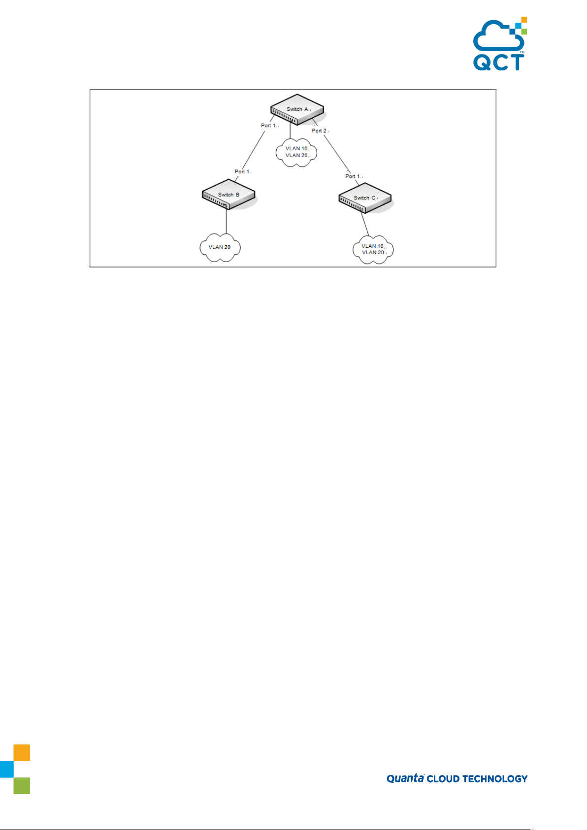
Figure 3-12: Single STP Topology
For VLAN 10 this single STP topology is fine and presents no limitations or inefficiencies. On the other hand,
VLAN 20's traffic pattern is inefficient. All frames from Switch B will have to traverse a path through Switch A
before arriving at Switch C. If the Port 2 on Switch B and Switch C could be used, these inefficiencies could be
eliminated. MSTP does just that, by allowing the configuration of MSTIs based upon a VLAN or groups of
VLANs. In this simple case, VLAN 10 could be associated with Multiple Spanning Tree Instance (MSTI)1 with
an active topology similar to Figure 16 and VLAN 20 could be associated with MSTI 2 where Port 1 on both
Switch A and Switch B begin discarding and all others forwarding. This simple modification creates an active
topology with a better distribution of network traffic and an increase in available bandwidth.
The logical representation of the MSTP environment for these three switches is shown in Figure 13.
90

Figure 3-13: Logical MSTP Environment
For MSTP to correctly establish the different MSTIs as above, some additional changes are required. For
example, the configuration would have to be the same on each and every bridge. That means that Switch B
would have to add VLAN 10 to its list of supported VLANs. This is necessary with MSTP to allow the
formation of Regions made up of all switches that exchange the same MST Configuration Identifier. It is
within only these MST Regions that multiple instances can exist. It will also allow the election of Regional
Root Bridges for each instance. One common and internal spanning tree (CIST) Regional Root for the CIST
and an MSTI Regional Root Bridge per instance will enable the possibility of alternate paths through each
Region. Above Switch A is elected as both the MSTI 1 Regional Root and the CIST Regional Root Bridge, and
after adjusting the Bridge Priority on Switch C in MSTI 2, it would be elected as the MSTI 2 Regional Root.
91

To further illustrate the full connectivity in an MSTP active topology, the following rules apply:
1. Each Bridge or LAN is in only one Region.
2. Every frame is associated with only one VID.
3. Frames are allocated either to the IST or MSTI within any given Region.
4. The internal spanning tree (IST) and each MSTI provides full and simple connectivity between all LANs and
Bridges in a Region.
5. All Bridges within a Region reach a consistent agreement as to which ports interconnect that Region to a
different Region and label those as Boundary Ports.
6. At the Boundary Ports, frames allocated to the CIST or MSTIs are forwarded or not forwarded alike.
7. The CIST provides full and simple connectivity between all LANs and Bridges in the network.
3.8.4. Optional STP Features
QNOS software supports the following optional STP features:
• BPDU flooding
• Edge Port
• BPDU filtering
• Root guard
• Loop guard
• BPDU protection
3.8.4.1. BPDU Flooding
The BPDU flooding feature determines the behavior of the switch when it receives a BPDU on a port that is
disabled for spanning tree. If BPDU flooding is configured, the switch will flood the received BPDU to all the
ports on the switch which are similarly disabled for spanning tree.
3.8.4.2. Edge Port
The Edge Port feature reduces the STP convergence time by allowing ports that are connected to end devices
(such as a desktop computer, printer, or file server) to transition to the forwarding state without going
through the listening and learning states.
3.8.4.3. PDU Filtering
92

Ports that have the Edge Port feature enabled continue to transmit BPDUs. The BPDU filtering feature
prevents ports configured as edge ports from sending BPDUs.
If BPDU filtering is configured globally on the switch, the feature is automatically enabled on all operational
ports where the Edge Port feature is enabled. These ports are typically connected to hosts that drop BPDUs.
However, if an operational edge port receives a BPDU, the BPDU filtering feature disables the Edge Port
feature and allows the port to participate in the spanning-tree calculation.
Enabling BPDU filtering on a specific port prevents the port from sending BPDUs and allows the port to
drop any BPDUs it receives.
3.8.4.4. Root Guard
Enabling root guard on a port ensures that the port does not become a root port or a blocked port. When a
switch is elected as the root bridge, all ports are designated ports unless two or more ports of the root
bridge are connected together. If the switch receives superior STP BPDUs on a root-guard enabled port, the
root guard feature moves this port to a root-inconsistent STP state, which is effectively equal to a listening
state. No traffic is forwarded across this port. In this way, the root guard feature enforces the position of
the root bridge.
When the STP mode is MSTP, the port may be a designated port in one MSTI and an alternate port in the
CIST, etc. Root guard is a per port (not a per port per instance command) configuration, so all the MSTP
instances this port participates in should not be in a root role.
3.8.4.5. Loop Guard
Loop guard protects a network from forwarding loops induced by BPDU packet loss. The reasons for failing
to receive packets are numerous, including heavy traffic, software problems, incorrect configuration, and
unidirectional link failure. When a non-designated port no longer receives BPDUs, the spanning-tree
algorithm considers that this link is loop free and begins transitioning the link from blocking to forwarding.
Once in forwarding state, the link may create a loop in the network.
Enabling loop guard prevents such accidental loops. When a port is no longer receiving BPDUs and the max
age timer expires, the port is moved to a
state, traffic is not forwarded so the port behaves as if it is in the blocking state. The port will remain in this
state
until it
receives a BPDU. It will then transition through the normal spanning tree states based on the
information in the received BPDU.
Note: Loop Guard should be
backup roles. Root ports and designated ports should not have loop guard enabled so that they can forward
traffic
configured
loop-inconsistent
only on
non-designated
blocking state. In the
ports. These include ports in alternate or
loop-inconsistent
blocking
3.8.4.6. BPDU Protection
When the switch is used as an access layer device, most ports function as edge ports that connect to a
device such as a desktop computer or file server. The port has a single, direct connection and is configured as
an edge port to implement the fast transition to a forwarding state. When the port receives a BPDU packet,
the system sets it to non-edge port and recalculates the spanning tree, which causes network topology
93

flapping. In normal cases, these ports do not receive any BPDU packets. However, someone may forge BPDU
to maliciously attack the switch and cause network flapping.
BPDU protection can be enabled in RSTP to prevent such attacks. When BPDU protection is enabled, the
switch disables an edge port that has received BPDU and notifies the network manager about it.
3.8.5. STP Configuring Examples
This section contains the following examples:
Configuring STP
Configuring MSTP
3.8.5.1. Configuring STP
This example shows a LAN with four switches. On each switch, ports 1, 2, and 3 connect to other switches, and
ports 4–20 connect to hosts (in Figure 14, each PC represents 17 host systems).
Figure 3-14: STP Example Network Diagram
Of the four switches in Figure 14, the administrator decides that Switch A is the most centrally located in the
network and is the least likely to be moved or redeployed. For these reasons, the administrator selects it as
the root bridge for the spanning tree. The administrator configures Switch A with the highest priority and
uses the default priority values for Switch B, Switch C, and Switch D.
For all switches, the administrator also configures ports 4–17 in Port Fast mode because these ports are
connected to hosts and can transition directly to the Forwarding state to speed up the connection time
between the hosts and the network.
94

The administrator also configures Port Fast BPDU filtering and Loop Guard to extend STP's capability to
prevent network loops. For all other STP settings, the administrator uses the default STP values.
To configure the switch:
1. Configure spanning tree mode to STP mode (IEEE 802.1d).
(QCT) #config
(QCT) (Config)#spanning-tree mode stp
2. Connect to Switch A and configure the priority to be higher (a lower value) than the other switches,
which use the default value of 32768.
(QCT) #config
(QCT) (Config)#spanning-tree mst priority 0 8192
3. Configure ports 4–20 to be in Edge Port mode.
(QCT) (Config)#interface range 0/4-0/20
(QCT) (Interface 0/4-0/20)#spanning-tree edgeport
(QCT) (Interface 0/4-0/20)#exit
4. Enable Loop Guard on ports 1–3 to help prevent network loops that might be caused if a port quits
receiving BPDUs.
(QCT) (Config)#interface range 0/1-0/3
(QCT) (Interface 0/1-0/3)#spanning-tree guard loop
(QCT) (Interface 0/1-0/3)#exit
5. Enable Port Fast BPDU Filter on ports 4-20. This feature affects only access ports that have the Edge Port
feature enabled.
(QCT) (Config)#interface range 0/4-0/20
(QCT) (Interface 0/4-0/20)#spanning-tree bpdufilter default
6. Repeat Step 1, Step 3 through Step 5 on Switch B, Switch C, and Switch D to complete the configuration.
3.8.5.2. Configuring MSTP
This example shows how to configure IEEE 802.1s Multiple Spanning Tree (MST) protocol on the switches
shown in Figure 15.
95

Figure 3-15: MSTP Configuration Example
To make multiple switches be part of the same MSTP region, make sure the STP operational mode for all
switches is MSTP. Also, make sure the MST region name and revision level are the same for all switches in the
region.
To configure the switches:
1. Create VLAN 10 and VLAN 20 (all switches).
Note: Even Switch B does not have any ports that are members of VLAN 10, this VLAN must be created to
allow the formation of MST regions made up of all bridges that exchange the same MST Configuration
Identifier. It is only within these MST Regions that multiple instances can exist.
(QCT) #config
(QCT) (Config)#vlan database
(QCT) (Vlan)#vlan 10,20
(QCT) (Vlan)#exit
2. Set the STP operational mode to MSTP.
(QCT) #config
(QCT) (Config)#spanning-tree mode mstp
3. Create MST instance 10 and associate it to VLAN 10.
(QCT) (Config)#spanning-tree mst instance 10
(QCT) (Config)#spanning-tree mst vlan 10 10
4. Create MST instance 20 and associate it to VLAN 20.
(QCT) (Config)#spanning-tree mst instance 20
(QCT) (Config)#spanning-tree mst vlan 20 20
96

5. Change the region name so that all the bridges that want to be part of the same region can form the
region.
(QCT) (Config)#spanning-tree configuration name QCT
6. (Switch A only) Make Switch A the Regional Root for MSTI 1 by configuring a higher priority for MST ID 10.
(QCT) (Config)#spanning-tree mst priority 10 12288
7. (Switch A only) Change the priority of MST ID 20 to ensure Switch C is the Regional Root bridge for this
MSTI.
(QCT) (Config)#spanning-tree mst priority 20 61440
8. (Switch C only) Change the priority of Switch C to force it to be the root bridge for MST 20.
(QCT) (Config)#spanning-tree mst priority 20 12288
(QCT) (Config)#exit
3.9. IGMP Snooping
IGMP Snooping is a layer-2 feature that allows the switch to dynamically add or remove ports from IP
multicast groups by listening to IGMP join and leave requests. By “snooping” the IGMP packets transmitted
between hosts and routers, the IGMP Snooping feature enables the switch to forward IP multicast traffic
more intelligently and help conserve bandwidth.
Based on the IGMP query and report messages, the switch forwards traffic only to the ports that request
the multicast traffic. This prevents the switch from broadcasting the traffic to all ports and possibly
affecting network performance. The switch uses the information in the IGMP packets as they are being
forwarded throughout the network to determine which segments should receive packets directed to the
group address.
3.9.1. IGMP Snooping Querier
When PIM and IGMP are enabled in a network with IP multicast routing, the IP multicast router acts as the
IGMP querier. However, if the IP-multicast traffic in a VLAN needs to be Layer 2 switched only, an IPmulticast router is not required. The IGMP Snooping Querier can perform the IGMP snooping functions on
the VLAN.
Without an IP-multicast router on a VLAN, you must configure another switch as the IGMP querier so that it
can send queries.
When the IGMP snooping querier is enabled, the IGMP snooping querier sends out periodic IGMP queries
that trigger IGMP report messages from the switch that wants to receive IP multicast traffic. The IGMP
snooping feature listens to these IGMP reports to establish appropriate forwarding.
3.9.2. Configuring IGMP Snooping
This example configures IGMP snooping on the switch to limit multicast traffic and to allow L2 multicast
forwarding on a single VLAN. The IP-multicast traffic in VLAN 100 needs to be Layer 2 switched only, so the
IGMP snooping querier is enabled on the switch to perform the IGMP snooping functions on the VLAN, if
97

necessary. The switch can send queries even if it is not the IGMP snooping querier and will use 0.0.0.0 as the
source IP address. This will not cause any disruption to the operation of external querier.
In this configuration, an IP-multicast router is not required.
The three hosts in Figure 16 are connected to ports that enabled for IGMP snooping and are members of
VLAN
100. Port 24 is a trunk port and connects the switch to the data center, where the L3 multicast router is
located.
Figure 3-16: Switch with IGMP Snooping
To configure the switch:
1. Enable IGMP snooping globally.
(QCT) #configure
(QCT) (Config)#ip igmp snooping
2. Enable the IGMP snooping querier on the switch. If there are no other IGMP snooping queriers, this
switch will become the IGMP snooping querier for the local network. If an external querier is discovered, this
switch will not be a querier.
(QCT) (Config)#ip igmp snooping querier
3. Create VLAN 100
(QCT) (Config)#vlan database
(QCT) (Vlan)#vlan 100
4. Enable IGMP snooping on VLAN 100.
(QCT) (Vlan)#set igmp 100
5. Enable the IGMP snooping querier on VLAN 100.
(QCT) (Config)#ip igmp snooping querier vlan 100
98

6. View the VLAN routing interface information.
(QCT) #show ip interface brief
Netdir Multi
Interface State IP Address IP Mask Method Bcast CastFwd
---------- ----- --------------- --------------- --------------- -------- -------- --------
vlan 1 Down 0.0.0.0 0.0.0.0 Primary None Disable Disable
vlan 100 Down 0.0.0.0 0.0.0.0 Primary None Disable Disable
7. Configure an IP address for VLAN 100. This address will be used as the IGMP snooping querier address if
this switch becomes the querier.
(QCT) #configure
(QCT) (Config)#interface vlan 100
(QCT) (if-vlan100)#ip address 192.168.10.2 255.255.255.0
(QCT) (if-vlan100)#exit
8. Specify the address to use as the source address for IGMP queries sent from any interface. The global
querier address is the IP address of VLAN 100.
(QCT) (Config)#ip igmp snooping querier address 192.168.10.2
9. Enable IGMP snooping on ports 1–3.
(QCT) (Config)#interface range 0/1-0/3
(QCT) (Interface 0/1-0/3)#ip igmp snooping interfacemode
10. Configure ports 1–3 as members of VLAN 100.
(QCT) (Interface 0/1-0/3)#switchport allowed vlan add 100
(QCT) (Interface 0/1-0/3)#exit
11. Enable IGMP on port 24, and configure the port as a trunk port that connects to the data center switch.
(QCT) (Config)#interface 0/24
(QCT) (Interface 0/24)#ip igmp snooping interfacemode
(QCT) (Interface 0/24)#switchport allowed vlan add tagged 100
(QCT) (Interface 0/24)#exit
(QCT) (Config)#exit
12. Verify the IGMP snooping configuration.
(QCT) #show igmp snooping
Admin Mode..................................... Enable
Multicast Control Frame Count.................. 0
IGMP Snooping Router-Alert check............... Disabled
Interfaces Enabled for IGMP Snooping........... 0/1
99

100
01:00:5E:01:01:01
IGMP
Dynamic Network Assist
0/1
0/1
100 01:00:5E:01:01:02
IGMP Dynamic Network Assist
0/2 0/2
0/2
0/3
0/24
VLANs enabled for IGMP snooping................ 100
VLANs Block enabled for snooping............... None
(QCT) #show igmp snooping querier vlan 100
VLAN 100 : IGMP Snooping querier status
----------------------------------------------
IGMP Snooping Querier VLAN Mode................ Enable
Querier Election Participate Mode.............. Disable
Querier VLAN Address........................... 0.0.0.0
Operational State.............................. Querier
Operational version............................ 2
Operational Max Resp Time...................... 10
After performing the configuration in this example, Host A sends a join message for multicast group
225.1.1.1. Host B sends a join message for group 225.1.1.2. Because IGMP snooping is enabled on the
switch and on VLAN 100, the switch listens to the messages and dynamically adds Ports 1 and 2 to the
multicast address table. Port 3 did not send a join message, so it does not appear in the table, as the
following show command indicates.
(QCT) #show mac-address-table multicast
Fwd
VLAN ID MAC Address Source Type Description Interface Interface
------- ---------------- ------- ------- --------------- --------- ---------
When the video server sends multicast data to group 225.1.1.1, Port 1 participates and receives multicast
traffic, but Port 2 does not participate because it is a member of a different multicast group. Without IGMP
snooping, all ports that are members of VLAN 100 would be flooded with traffic for all multicast groups,
which would greatly increase the amount of traffic on the switch.
3.9.3. IGMPv3/SSM Snooping
IGMPv3 adds support for source filtering, which is the ability for a system to report interest in receiving
packets only from specific source addresses, or from all but specific source addresses sent to a particular
100
 Loading...