

Page 1

STRATOS S210 Series
S210-X2A2J
Optimized 2-Socket, 4-GPGPU
2U Server
Technical Guide
Document Version: 1.0.1
Page 2

TABLE OF CONTENTS
I
TABLE OF CONTENTS
About the Server
Introduction 1-1
System Features . . . . . . . . . . . . . . . . . . . . . . . . . . . . . . . . . . . . . . . . . . . . . . . . . . . . . . . . . . . . . . . . . . . . . .1-1
Specifications . . . . . . . . . . . . . . . . . . . . . . . . . . . . . . . . . . . . . . . . . . . . . . . . . . . . . . . . . . . . . . . . . . . . . . .1-1
Package Contents 1-3
A Tour of the System 1-4
System Overview . . . . . . . . . . . . . . . . . . . . . . . . . . . . . . . . . . . . . . . . . . . . . . . . . . . . . . . . . . . . . . . . . . . . . .1-4
System Front View. . . . . . . . . . . . . . . . . . . . . . . . . . . . . . . . . . . . . . . . . . . . . . . . . . . . . . . . . . . . . . . . . . . . .1-5
Control Panel . . . . . . . . . . . . . . . . . . . . . . . . . . . . . . . . . . . . . . . . . . . . . . . . . . . . . . . . . . . . . . . . . . . . . . .1-5
System Rear View . . . . . . . . . . . . . . . . . . . . . . . . . . . . . . . . . . . . . . . . . . . . . . . . . . . . . . . . . . . . . . . . . . . . .1-6
I/O Ports on Rear Panel . . . . . . . . . . . . . . . . . . . . . . . . . . . . . . . . . . . . . . . . . . . . . . . . . . . . . . . . . . . . . . .1-6
LED Status Definitions . . . . . . . . . . . . . . . . . . . . . . . . . . . . . . . . . . . . . . . . . . . . . . . . . . . . . . . . . . . . . . . . . .1-7
Front Control Panel . . . . . . . . . . . . . . . . . . . . . . . . . . . . . . . . . . . . . . . . . . . . . . . . . . . . . . . . . . . . . . . . . .1-7
Amber Blinking Identification . . . . . . . . . . . . . . . . . . . . . . . . . . . . . . . . . . . . . . . . . . . . . . . . . . . . . . . . . . .1-8
LAN LED . . . . . . . . . . . . . . . . . . . . . . . . . . . . . . . . . . . . . . . . . . . . . . . . . . . . . . . . . . . . . . . . . . . . . . . . . .1-8
HDD LED . . . . . . . . . . . . . . . . . . . . . . . . . . . . . . . . . . . . . . . . . . . . . . . . . . . . . . . . . . . . . . . . . . . . . . . . . .1-9
Page 3

TABLE OF CONTENTS
II
Installing Hardware
Safety Measures 2-1
Hard Disk Drive 2-2
Removing a Swappable HDD Assembly . . . . . . . . . . . . . . . . . . . . . . . . . . . . . . . . . . . . . . . . . . . . . . . . . . . .2-2
Installing a Swappable HDD Assembly . . . . . . . . . . . . . . . . . . . . . . . . . . . . . . . . . . . . . . . . . . . . . . . . . . . . .2-3
Removing an HDD Module . . . . . . . . . . . . . . . . . . . . . . . . . . . . . . . . . . . . . . . . . . . . . . . . . . . . . . . . . . . . . .2-3
Installing an HDD Module . . . . . . . . . . . . . . . . . . . . . . . . . . . . . . . . . . . . . . . . . . . . . . . . . . . . . . . . . . . . . . .2-4
Power Supply Unit 2-5
Removing a PSU . . . . . . . . . . . . . . . . . . . . . . . . . . . . . . . . . . . . . . . . . . . . . . . . . . . . . . . . . . . . . . . . . . . . . .2-5
Installing a PSU . . . . . . . . . . . . . . . . . . . . . . . . . . . . . . . . . . . . . . . . . . . . . . . . . . . . . . . . . . . . . . . . . . . . . . .2-6
Fan 2-7
Removing a Swappable Fan Assembly . . . . . . . . . . . . . . . . . . . . . . . . . . . . . . . . . . . . . . . . . . . . . . . . . . . . .2-7
Installing a Swappable Fan Assembly . . . . . . . . . . . . . . . . . . . . . . . . . . . . . . . . . . . . . . . . . . . . . . . . . . . . . .2-7
Top Cover 2-9
Removing a Top Cover . . . . . . . . . . . . . . . . . . . . . . . . . . . . . . . . . . . . . . . . . . . . . . . . . . . . . . . . . . . . . . . . .2-9
Installing a Top Cover . . . . . . . . . . . . . . . . . . . . . . . . . . . . . . . . . . . . . . . . . . . . . . . . . . . . . . . . . . . . . . . . . .2-9
Page 4

TABLE OF CONTENTS
III
General-purpose Graphics Processing Units 2-10
GPGPU Location Overview . . . . . . . . . . . . . . . . . . . . . . . . . . . . . . . . . . . . . . . . . . . . . . . . . . . . . . . . . . . . .2-10
Screw Tension Specification . . . . . . . . . . . . . . . . . . . . . . . . . . . . . . . . . . . . . . . . . . . . . . . . . . . . . . . . . . . .2-10
Removing a GPGPU1 Module. . . . . . . . . . . . . . . . . . . . . . . . . . . . . . . . . . . . . . . . . . . . . . . . . . . . . . . . . . .2-10
Installing a GPGPU1 Module . . . . . . . . . . . . . . . . . . . . . . . . . . . . . . . . . . . . . . . . . . . . . . . . . . . . . . . . . . . .2-15
Removing a GPGPU2 Module. . . . . . . . . . . . . . . . . . . . . . . . . . . . . . . . . . . . . . . . . . . . . . . . . . . . . . . . . . .2-19
Installing a GPGPU2 Module . . . . . . . . . . . . . . . . . . . . . . . . . . . . . . . . . . . . . . . . . . . . . . . . . . . . . . . . . . . .2-23
Removing a GPGPU3 Module. . . . . . . . . . . . . . . . . . . . . . . . . . . . . . . . . . . . . . . . . . . . . . . . . . . . . . . . . . .2-28
Installing a GPGPU3 Module . . . . . . . . . . . . . . . . . . . . . . . . . . . . . . . . . . . . . . . . . . . . . . . . . . . . . . . . . . . .2-33
Removing a GPGPU4 Module. . . . . . . . . . . . . . . . . . . . . . . . . . . . . . . . . . . . . . . . . . . . . . . . . . . . . . . . . . .2-38
Installing a GPGPU4 Module . . . . . . . . . . . . . . . . . . . . . . . . . . . . . . . . . . . . . . . . . . . . . . . . . . . . . . . . . . . .2-42
GPGPU Dummy Bracket 2-46
Removing a GPGPU Dummy Bracket . . . . . . . . . . . . . . . . . . . . . . . . . . . . . . . . . . . . . . . . . . . . . . . . . . . . .2-46
Installing a GPGPU Dummy Bracket . . . . . . . . . . . . . . . . . . . . . . . . . . . . . . . . . . . . . . . . . . . . . . . . . . . . . .2-48
Air Duct 2-51
Removing a Memory Air Duct . . . . . . . . . . . . . . . . . . . . . . . . . . . . . . . . . . . . . . . . . . . . . . . . . . . . . . . . . . .2-51
Installing a Memory Air Duct . . . . . . . . . . . . . . . . . . . . . . . . . . . . . . . . . . . . . . . . . . . . . . . . . . . . . . . . . . . .2-52
Removing a Mainboard Air Duct . . . . . . . . . . . . . . . . . . . . . . . . . . . . . . . . . . . . . . . . . . . . . . . . . . . . . . . . .2-52
Installing a Mainboard Air Duct . . . . . . . . . . . . . . . . . . . . . . . . . . . . . . . . . . . . . . . . . . . . . . . . . . . . . . . . . .2-53
Removing a PDB Air Duct . . . . . . . . . . . . . . . . . . . . . . . . . . . . . . . . . . . . . . . . . . . . . . . . . . . . . . . . . . . . . .2-53
Page 5

TABLE OF CONTENTS
IV
Installing a PDB Air Duct . . . . . . . . . . . . . . . . . . . . . . . . . . . . . . . . . . . . . . . . . . . . . . . . . . . . . . . . . . . . . . .2-54
Removing a GPGPU3 Air Duct . . . . . . . . . . . . . . . . . . . . . . . . . . . . . . . . . . . . . . . . . . . . . . . . . . . . . . . . . .2-54
Installing a GPGPU3 Air Duct . . . . . . . . . . . . . . . . . . . . . . . . . . . . . . . . . . . . . . . . . . . . . . . . . . . . . . . . . . .2-55
Memory Modules 2-56
General Guidelines . . . . . . . . . . . . . . . . . . . . . . . . . . . . . . . . . . . . . . . . . . . . . . . . . . . . . . . . . . . . . . . . . . .2-56
Memory Population Rules . . . . . . . . . . . . . . . . . . . . . . . . . . . . . . . . . . . . . . . . . . . . . . . . . . . . . . . . . . . . . .2-56
Removing a Memory Module. . . . . . . . . . . . . . . . . . . . . . . . . . . . . . . . . . . . . . . . . . . . . . . . . . . . . . . . . . . .2-57
Installing a Memory Module . . . . . . . . . . . . . . . . . . . . . . . . . . . . . . . . . . . . . . . . . . . . . . . . . . . . . . . . . . . . .2-58
Memory Support List . . . . . . . . . . . . . . . . . . . . . . . . . . . . . . . . . . . . . . . . . . . . . . . . . . . . . . . . . . . . . . . . . .2-59
Processor Heat Sinks 2-61
Removing a Heat Sink . . . . . . . . . . . . . . . . . . . . . . . . . . . . . . . . . . . . . . . . . . . . . . . . . . . . . . . . . . . . . . . . .2-61
Installing a Heat Sink . . . . . . . . . . . . . . . . . . . . . . . . . . . . . . . . . . . . . . . . . . . . . . . . . . . . . . . . . . . . . . . . . .2-62
Processors 2-63
Removing a Processor. . . . . . . . . . . . . . . . . . . . . . . . . . . . . . . . . . . . . . . . . . . . . . . . . . . . . . . . . . . . . . . . .2-63
Installing a Processor. . . . . . . . . . . . . . . . . . . . . . . . . . . . . . . . . . . . . . . . . . . . . . . . . . . . . . . . . . . . . . . . . .2-65
Mainboard Module 2-66
Removing a Mainboard Module . . . . . . . . . . . . . . . . . . . . . . . . . . . . . . . . . . . . . . . . . . . . . . . . . . . . . . . . . .2-66
Installing a Mainboard Module . . . . . . . . . . . . . . . . . . . . . . . . . . . . . . . . . . . . . . . . . . . . . . . . . . . . . . . . . . .2-67
Page 6

TABLE OF CONTENTS
V
Power Distribution Board 2-69
Removing a PDB . . . . . . . . . . . . . . . . . . . . . . . . . . . . . . . . . . . . . . . . . . . . . . . . . . . . . . . . . . . . . . . . . . . . .2-69
Installing a PDB . . . . . . . . . . . . . . . . . . . . . . . . . . . . . . . . . . . . . . . . . . . . . . . . . . . . . . . . . . . . . . . . . . . . . .2-69
Fan Board 2-71
Removing a Fan Board . . . . . . . . . . . . . . . . . . . . . . . . . . . . . . . . . . . . . . . . . . . . . . . . . . . . . . . . . . . . . . . .2-71
Installing a Fan Board . . . . . . . . . . . . . . . . . . . . . . . . . . . . . . . . . . . . . . . . . . . . . . . . . . . . . . . . . . . . . . . . .2-72
BIOS
BIOS Setup Utility 3-1
Operation . . . . . . . . . . . . . . . . . . . . . . . . . . . . . . . . . . . . . . . . . . . . . . . . . . . . . . . . . . . . . . . . . . . . . . . . . . . .3-1
Setup Page Layout . . . . . . . . . . . . . . . . . . . . . . . . . . . . . . . . . . . . . . . . . . . . . . . . . . . . . . . . . . . . . . . . . . . .3-1
Entering BIOS Setup . . . . . . . . . . . . . . . . . . . . . . . . . . . . . . . . . . . . . . . . . . . . . . . . . . . . . . . . . . . . . . . . . . .3-2
Keyboard Commands . . . . . . . . . . . . . . . . . . . . . . . . . . . . . . . . . . . . . . . . . . . . . . . . . . . . . . . . . . . . . . . . . .3-2
Menu Selection Bar . . . . . . . . . . . . . . . . . . . . . . . . . . . . . . . . . . . . . . . . . . . . . . . . . . . . . . . . . . . . . . . . . . . .3-4
Server Platform Setup Utility Screens . . . . . . . . . . . . . . . . . . . . . . . . . . . . . . . . . . . . . . . . . . . . . . . . . . . . . .3-4
Main Screen. . . . . . . . . . . . . . . . . . . . . . . . . . . . . . . . . . . . . . . . . . . . . . . . . . . . . . . . . . . . . . . . . . . . . . . . . .3-5
Advanced Screen. . . . . . . . . . . . . . . . . . . . . . . . . . . . . . . . . . . . . . . . . . . . . . . . . . . . . . . . . . . . . . . . . . . . . .3-7
PCI Screen . . . . . . . . . . . . . . . . . . . . . . . . . . . . . . . . . . . . . . . . . . . . . . . . . . . . . . . . . . . . . . . . . . . . . . . . .3-8
WHEA Support Screen. . . . . . . . . . . . . . . . . . . . . . . . . . . . . . . . . . . . . . . . . . . . . . . . . . . . . . . . . . . . . . . .3-9
Processor Configuration Screen . . . . . . . . . . . . . . . . . . . . . . . . . . . . . . . . . . . . . . . . . . . . . . . . . . . . . . .3-10
Page 7

TABLE OF CONTENTS
VI
Runtime Error Logging Screen. . . . . . . . . . . . . . . . . . . . . . . . . . . . . . . . . . . . . . . . . . . . . . . . . . . . . . . . .3-15
SATA Controller Screen . . . . . . . . . . . . . . . . . . . . . . . . . . . . . . . . . . . . . . . . . . . . . . . . . . . . . . . . . . . . . .3-16
USB Configuration Screen . . . . . . . . . . . . . . . . . . . . . . . . . . . . . . . . . . . . . . . . . . . . . . . . . . . . . . . . . . . .3-17
Super I/O Configuration Screen . . . . . . . . . . . . . . . . . . . . . . . . . . . . . . . . . . . . . . . . . . . . . . . . . . . . . . . .3-18
Onboard Device Configuration Screen. . . . . . . . . . . . . . . . . . . . . . . . . . . . . . . . . . . . . . . . . . . . . . . . . . .3-19
Console Redirection Screen. . . . . . . . . . . . . . . . . . . . . . . . . . . . . . . . . . . . . . . . . . . . . . . . . . . . . . . . . . .3-21
Chipset Screen . . . . . . . . . . . . . . . . . . . . . . . . . . . . . . . . . . . . . . . . . . . . . . . . . . . . . . . . . . . . . . . . . . . . . .3-24
North Bridge Screen. . . . . . . . . . . . . . . . . . . . . . . . . . . . . . . . . . . . . . . . . . . . . . . . . . . . . . . . . . . . . . . . .3-25
South Bridge Screen . . . . . . . . . . . . . . . . . . . . . . . . . . . . . . . . . . . . . . . . . . . . . . . . . . . . . . . . . . . . . . . .3-28
ME Subsystem Screen. . . . . . . . . . . . . . . . . . . . . . . . . . . . . . . . . . . . . . . . . . . . . . . . . . . . . . . . . . . . . . .3-30
Server Management Screen . . . . . . . . . . . . . . . . . . . . . . . . . . . . . . . . . . . . . . . . . . . . . . . . . . . . . . . . . . . .3-31
System Event Log Screen . . . . . . . . . . . . . . . . . . . . . . . . . . . . . . . . . . . . . . . . . . . . . . . . . . . . . . . . . . . .3-33
FRU Information . . . . . . . . . . . . . . . . . . . . . . . . . . . . . . . . . . . . . . . . . . . . . . . . . . . . . . . . . . . . . . . . . . . .3-34
BMC Network Configuration. . . . . . . . . . . . . . . . . . . . . . . . . . . . . . . . . . . . . . . . . . . . . . . . . . . . . . . . . . .3-35
Boot Option Screen . . . . . . . . . . . . . . . . . . . . . . . . . . . . . . . . . . . . . . . . . . . . . . . . . . . . . . . . . . . . . . . . . . .3-36
Network Device BBS Priorities Screen. . . . . . . . . . . . . . . . . . . . . . . . . . . . . . . . . . . . . . . . . . . . . . . . . . .3-38
Security Screen . . . . . . . . . . . . . . . . . . . . . . . . . . . . . . . . . . . . . . . . . . . . . . . . . . . . . . . . . . . . . . . . . . . . . .3-39
Exit Screen. . . . . . . . . . . . . . . . . . . . . . . . . . . . . . . . . . . . . . . . . . . . . . . . . . . . . . . . . . . . . . . . . . . . . . . . . .3-45
Loading BIOS Defaults . . . . . . . . . . . . . . . . . . . . . . . . . . . . . . . . . . . . . . . . . . . . . . . . . . . . . . . . . . . . . . . .3-47
Page 8

TABLE OF CONTENTS
VII
BIOS Update Utility 3-48
BIOS Update Utility . . . . . . . . . . . . . . . . . . . . . . . . . . . . . . . . . . . . . . . . . . . . . . . . . . . . . . . . . . . . . . . . . . .3-48
Recovery Mode . . . . . . . . . . . . . . . . . . . . . . . . . . . . . . . . . . . . . . . . . . . . . . . . . . . . . . . . . . . . . . . . . . . . . .3-48
Recovery Flow . . . . . . . . . . . . . . . . . . . . . . . . . . . . . . . . . . . . . . . . . . . . . . . . . . . . . . . . . . . . . . . . . . . . .3-49
Clear CMOS. . . . . . . . . . . . . . . . . . . . . . . . . . . . . . . . . . . . . . . . . . . . . . . . . . . . . . . . . . . . . . . . . . . . . . . . .3-50
Clear Password . . . . . . . . . . . . . . . . . . . . . . . . . . . . . . . . . . . . . . . . . . . . . . . . . . . . . . . . . . . . . . . . . . . . . .3-50
Server Management 3-51
Console Redirection. . . . . . . . . . . . . . . . . . . . . . . . . . . . . . . . . . . . . . . . . . . . . . . . . . . . . . . . . . . . . . . . . . .3-51
Serial Configuration Settings . . . . . . . . . . . . . . . . . . . . . . . . . . . . . . . . . . . . . . . . . . . . . . . . . . . . . . . . . .3-51
Keystroke Mapping. . . . . . . . . . . . . . . . . . . . . . . . . . . . . . . . . . . . . . . . . . . . . . . . . . . . . . . . . . . . . . . . . .3-51
Limitations . . . . . . . . . . . . . . . . . . . . . . . . . . . . . . . . . . . . . . . . . . . . . . . . . . . . . . . . . . . . . . . . . . . . . . . .3-52
Interface to Server Management . . . . . . . . . . . . . . . . . . . . . . . . . . . . . . . . . . . . . . . . . . . . . . . . . . . . . . .3-52
PXE Boot . . . . . . . . . . . . . . . . . . . . . . . . . . . . . . . . . . . . . . . . . . . . . . . . . . . . . . . . . . . . . . . . . . . . . . . . . . .3-52
Checkpoints . . . . . . . . . . . . . . . . . . . . . . . . . . . . . . . . . . . . . . . . . . . . . . . . . . . . . . . . . . . . . . . . . . . . . . . . .3-53
Checkpoint Ranges . . . . . . . . . . . . . . . . . . . . . . . . . . . . . . . . . . . . . . . . . . . . . . . . . . . . . . . . . . . . . . . . .3-53
Standard Checkpoints . . . . . . . . . . . . . . . . . . . . . . . . . . . . . . . . . . . . . . . . . . . . . . . . . . . . . . . . . . . . . . .3-53
DXE Phase. . . . . . . . . . . . . . . . . . . . . . . . . . . . . . . . . . . . . . . . . . . . . . . . . . . . . . . . . . . . . . . . . . . . . . . .3-56
ACPI/ASL Checkpoints . . . . . . . . . . . . . . . . . . . . . . . . . . . . . . . . . . . . . . . . . . . . . . . . . . . . . . . . . . . . . .3-59
Extra Checkpoint Ranges . . . . . . . . . . . . . . . . . . . . . . . . . . . . . . . . . . . . . . . . . . . . . . . . . . . . . . . . . . . . . .3-59
Page 9

TABLE OF CONTENTS
VIII
BMC
Server Management Software 4-1
Introduction . . . . . . . . . . . . . . . . . . . . . . . . . . . . . . . . . . . . . . . . . . . . . . . . . . . . . . . . . . . . . . . . . . . . . . . . . .4-1
BMC Key Features and Functions . . . . . . . . . . . . . . . . . . . . . . . . . . . . . . . . . . . . . . . . . . . . . . . . . . . . . . . . .4-1
Power System . . . . . . . . . . . . . . . . . . . . . . . . . . . . . . . . . . . . . . . . . . . . . . . . . . . . . . . . . . . . . . . . . . . . . . . .4-1
Front Panel User Interface. . . . . . . . . . . . . . . . . . . . . . . . . . . . . . . . . . . . . . . . . . . . . . . . . . . . . . . . . . . . . . .4-2
Power Button . . . . . . . . . . . . . . . . . . . . . . . . . . . . . . . . . . . . . . . . . . . . . . . . . . . . . . . . . . . . . . . . . . . . . . .4-2
ID Button . . . . . . . . . . . . . . . . . . . . . . . . . . . . . . . . . . . . . . . . . . . . . . . . . . . . . . . . . . . . . . . . . . . . . . . . . .4-2
LEDs. . . . . . . . . . . . . . . . . . . . . . . . . . . . . . . . . . . . . . . . . . . . . . . . . . . . . . . . . . . . . . . . . . . . . . . . . . . . . .4-2
LAN Interface . . . . . . . . . . . . . . . . . . . . . . . . . . . . . . . . . . . . . . . . . . . . . . . . . . . . . . . . . . . . . . . . . . . . . . . . .4-3
Session and User . . . . . . . . . . . . . . . . . . . . . . . . . . . . . . . . . . . . . . . . . . . . . . . . . . . . . . . . . . . . . . . . . . . .4-3
RMCP+. . . . . . . . . . . . . . . . . . . . . . . . . . . . . . . . . . . . . . . . . . . . . . . . . . . . . . . . . . . . . . . . . . . . . . . . . . . .4-4
Serial Over LAN . . . . . . . . . . . . . . . . . . . . . . . . . . . . . . . . . . . . . . . . . . . . . . . . . . . . . . . . . . . . . . . . . . . . . . .4-4
Time Sync . . . . . . . . . . . . . . . . . . . . . . . . . . . . . . . . . . . . . . . . . . . . . . . . . . . . . . . . . . . . . . . . . . . . . . . . . . .4-4
SEL . . . . . . . . . . . . . . . . . . . . . . . . . . . . . . . . . . . . . . . . . . . . . . . . . . . . . . . . . . . . . . . . . . . . . . . . . . . . . . . .4-4
Platform Event . . . . . . . . . . . . . . . . . . . . . . . . . . . . . . . . . . . . . . . . . . . . . . . . . . . . . . . . . . . . . . . . . . . . . . . .4-5
Platform Event Filter. . . . . . . . . . . . . . . . . . . . . . . . . . . . . . . . . . . . . . . . . . . . . . . . . . . . . . . . . . . . . . . . . .4-5
BMC Firmware Update . . . . . . . . . . . . . . . . . . . . . . . . . . . . . . . . . . . . . . . . . . . . . . . . . . . . . . . . . . . . . . . . .4-5
DOS Recovery Utility . . . . . . . . . . . . . . . . . . . . . . . . . . . . . . . . . . . . . . . . . . . . . . . . . . . . . . . . . . . . . . . . .4-5
WebUI Update . . . . . . . . . . . . . . . . . . . . . . . . . . . . . . . . . . . . . . . . . . . . . . . . . . . . . . . . . . . . . . . . . . . . . .4-5
Page 10

TABLE OF CONTENTS
X
BMC Recovery 4-6
Recovery Process in DOS System
. . . . . . . . . . . . . . . .
. . . . . . . . . . . . . . . .
. . . . . . . . . . . . . . . . . . . . . . .4-6
Recovery Process in Linux System . . . . . . . . . . . . . . . . . . . . . . . . . . . . . . . .
. . . . . . . . . . . . . . . . . . . . . . .4-6
Recovery Process in Windows System . . . . . . . . . . . . . . . . . . . . . . . . . . . . . . . . . . . . . . . . . . . . . . . . . . . .4-6
Web Graphical User Interface (GUI) for ESMS 4-7
Using the Web GUI . . . . . . . . . . . . . . . . . . . . . . . . . . . . . . . . . . . . . . . . . . . . . . . . . . . . . . . . . . . . . . . . . . .4-7
Login . . . . . . . . . . . . . . . . . . . . . . . . . . . . . . . . . . . . . . . . . . . . . . . . . . . . . . . . . . . . . . . . . . . . . . . . . . . . . .4-7
Dashboard . . . . . . . . . . . . . . . . . . . . . . . . . . . . . . . . . . . . . . . . . . . . . . . . . . . . . . . . . . . . . . . . . . . . . . . . . .4-9
Device Information . . . . . . . . . . . . . . . . . . . . . . . . . . . . . . . . . . . . . . . . . . . . . . . . . . . . . . . . . . . . . . . . . .4-9
Network Information . . . . . . . . . . . . . . . . . . . . . . . . . . . . . . . . . . . . . . . . . . . . . . . . . . . . . . . . . . . . . . . . .4-10
Sensor Monitoring . . . . . . . . . . . . . . . . . . . . . . . . . . . . . . . . . . . . . . . . . . . . . . . . . . . . . . . . . . . . . . . . . .4-10
Event Logs . . . . . . . . . . . . . . . . . . . . . . . . . . . . . . . . . . . . . . . . . . . . . . . . . . . . . . . . . . . . . . . . . . . . . . . .4-11
Server Information . . . . . . . . . . . . . . . . . . . . . . . . . . . . . . . . . . . . . . . . . . . . . . . . . . . . . . . . . . . . . . . . . . . .4-11
Page 11

TABLE OF CONTENTS
XI
FRU Information. . . . . . . . . . . . . . . . . . . . . . . . . . . . . . . . . . . . . . . . . . . . . . . . . . . . . . . . . . . . . . . . . . . . . .4-12
Server Component . . . . . . . . . . . . . . . . . . . . . . . . . . . . . . . . . . . . . . . . . . . . . . . . . . . . . . . . . . . . . . . . . .4-13
Server identify . . . . . . . . . . . . . . . . . . . . . . . . . . . . . . . . . . . . . . . . . . . . . . . . . . . . . . . . . . . . . . . . . . . . .4-14
Server Health Group . . . . . . . . . . . . . . . . . . . . . . . . . . . . . . . . . . . . . . . . . . . . . . . . . . . . . . . . . . . . . . . .4-15
Sensor Readings . . . . . . . . . . . . . . . . . . . . . . . . . . . . . . . . . . . . . . . . . . . . . . . . . . . . . . . . . . . . . . . . . . .4-15
Event Log
. . . . . . . . . . . . . . . . . . . . . . . . . . . . . . . . . . . . . .
. . . . . . . . . . . . . . . . . . . . . . . . . . . . . . . . . . .4-
17
Configuration Group. . . . . . . . . . . . . . . . . . . . . . . . . . . . . . . . . . . . . . . . . . . . . . . . . . . . . . . . . . . . . . . . . . .4-18
Active Directory . . . . . . . . . . . . . . . . . . . . . . . . . . . . . . . . . . . . . . . . . . . . . . . . . . . . . . . . . . . . . . . . . . . .4-18
DNS . . . . . . . . . . . . . . . . . . . . . . . . . . . . . . . . . . . . . . . . . . . . . . . . . . . . . . . . . . . . . . . . . . . . . . . . . . . . .4-21
LDAP/E-Directory . . . . . . . . . . . . . . . . . . . . . . . . . . . . . . . . . . . . . . . . . . . . . . . . . . . . . . . . . . . . . . . . . . .4-23
Mouse Mode. . . . . . . . . . . . . . . . . . . . . . . . . . . . . . . . . . . . . . . . . . . . . . . . . . . . . . . . . . . . . . . . . . . . . . .4-27
Network . . . . . . . . . . . . . . . . . . . . . . . . . . . . . . . . . . . . . . . . . . . . . . . . . . . . . . . . . . . . . . . . . . . . . . . . . .4-28
PEF
. . . . . . . . . . . . . . . . . . . . . . . . . . . . . .
. . . . . . . . . . . . . . . . . . . . . . . . . . . . . . . . . . . . . . . . . . . . . . .4-30
RADIUS . . . . . . . . . . . . . . . . . . . . . . . . . . . . . . . . . . . . . . . . . . . . . . . . . . . . . . . . . . . . . . . . . . . . . . . . . .4-36
Remote Session . . . . . . . . . . . . . . . . . . . . . . . . . . . . . . . . . . . . . . . . . . . . . . . . . . . . . . . . . . . . . . . . . . . .4-40
SMTP . . . . . . . . . . . . . . . . . . . . . . . . . . . . . . . . . . . . . . . . . . . . . . . . . . . . . . . . . . . . . . . . . . . . . . . . . . . .4-39
SOL . . . . . . . . . . . . . . . . . . . . . . . . . . . . . . . . . . . . . . . . . . . . . . . . . . . . . . . . . . . . . . . . . . . . . . . . . . . . .4-41
SSL. . . . . . . . . . . . . . . . . . . . . . . . . . . . . . . . . . . . . . . . . . . . . . . . . . . . . . . . . . . . . . . . . . . . . . . . . . . . . .4-42
User Management . . . . . . . . . . . . . . . . . . . . . . . . . . . . . . . . . . . . . . . . . . . . . . . . . . . . . . . . . . . . . . . . . .4-47
Virtual Media . . . . . . . . . . . . . . . . . . . . . . . . . . . . . . . . . . . . . . . . . . . . . . . . . . . . . . . . . . . . . . . . . . . . . .4-50
Page 12

TABLE OF CONTENTS
XII
Remote Control . . . . . . . . . . . . . . . . . . . . . . . . . . . . . . . . . . . . . . . . . . . . . . . . . . . . . . . . . . . . . . . . . . . . . .4-51
Console Redirection . . . . . . . . . . . . . . . . . . . . . . . . . . . . . . . . . . . . . . . . . . . . . . . . . . . . . . . . . . . . . . . . .4-51
Server Power Control . . . . . . . . . . . . . . . . . . . . . . . . . . . . . . . . . . . . . . . . . . . . . . . . . . . . . . . . . . . . . . . .4-57
Maintenance Group . . . . . . . . . . . . . . . . . . . . . . . . . . . . . . . . . . . . . . . . . . . . . . . . . . . . . . . . . . . . . . . . . . .4-58
BMC Firmware Update. . . . . . . . . . . . . . . . . . . . . . . . . . . . . . . . . . . . . . . . . . . . . . . . . . . . . . . . . . . . . . .4-59
BIOS Update
. . . . . . . . . . . . . . . . . . . . . . . . . . . . . . . . . . . . . . . . . . . . . . . . . . . . . . . . . . . . . . . . . . . . . .4-
60
Preserve Configuration. . . . . . . . . . . . . . . . . . . . . . . . . . . . . . . . . . . . . . . . . . . . . . . . . . . . . . . . . . . . . . .4-61
Restore Factory Defaults . . . . . . . . . . . . . . . . . . . . . . . . . . . . . . . . . . . . . . . . . . . . . . . . . . . . . . . . . . . . .4-61
Log Out . . . . . . . . . . . . . . . . . . . . . . . . . . . . . . . . . . . . . . . . . . . . . . . . . . . . . . . . . . . . . . . . . . . . . . . . . . . .4-62
User Privilege. . . . . . . . . . . . . . . . . . . . . . . . . . . . . . . . . . . . . . . . . . . . . . . . . . . . . . . . . . . . . . . . . . . . . . . .4-62
Jumpers and Connectors
Mainboard Connectors and Jumpers 5-1
Mainboard Connectors and LEDs . . . . . . . . . . . . . . . . . . . . . . . . . . . . . . . . . . . . . . . . . . . . . . . . . . . . . . . . .5-1
VGA Video Connector (J4A1) . . . . . . . . . . . . . . . . . . . . . . . . . . . . . . . . . . . . . . . . . . . . . . . . . . . . . . . . . .5-2
Rear USB Connector (J3A1) . . . . . . . . . . . . . . . . . . . . . . . . . . . . . . . . . . . . . . . . . . . . . . . . . . . . . . . . . . .5-2
NIC1 Connector (JA5A2) . . . . . . . . . . . . . . . . . . . . . . . . . . . . . . . . . . . . . . . . . . . . . . . . . . . . . . . . . . . . . .5-3
NIC2 Connector (JA5A1) . . . . . . . . . . . . . . . . . . . . . . . . . . . . . . . . . . . . . . . . . . . . . . . . . . . . . . . . . . . . . .5-3
Mainboard Jumpers . . . . . . . . . . . . . . . . . . . . . . . . . . . . . . . . . . . . . . . . . . . . . . . . . . . . . . . . . . . . . . . . . . . .5-4
Password Clear Jumper (J6B3) . . . . . . . . . . . . . . . . . . . . . . . . . . . . . . . . . . . . . . . . . . . . . . . . . . . . . . . . .5-4
BIOS Recovery Jumper (J6C2) . . . . . . . . . . . . . . . . . . . . . . . . . . . . . . . . . . . . . . . . . . . . . . . . . . . . . . . . .5-4
Page 13

TABLE OF CONTENTS
XIII
Protected RTC Jumper (J6C3). . . . . . . . . . . . . . . . . . . . . . . . . . . . . . . . . . . . . . . . . . . . . . . . . . . . . . . . . .5-5
ME Disable Jumper (J6B6) . . . . . . . . . . . . . . . . . . . . . . . . . . . . . . . . . . . . . . . . . . . . . . . . . . . . . . . . . . . .5-5
BMC Disable Jumper (J6C1) . . . . . . . . . . . . . . . . . . . . . . . . . . . . . . . . . . . . . . . . . . . . . . . . . . . . . . . . . . .5-5
SERIAL COM SW Jumper (J6B1) . . . . . . . . . . . . . . . . . . . . . . . . . . . . . . . . . . . . . . . . . . . . . . . . . . . . . . .5-6
Rail Kit Assembly
Rail Kit Assembly 6-1
Installing the Rack Brackets. . . . . . . . . . . . . . . . . . . . . . . . . . . . . . . . . . . . . . . . . . . . . . . . . . . . . . . . . . . . . .6-1
Installing the System Into the Rack . . . . . . . . . . . . . . . . . . . . . . . . . . . . . . . . . . . . . . . . . . . . . . . . . . . . . . . .6-3
Troubleshooting
Troubleshooting 7-1
Server Boot Issue Topics. . . . . . . . . . . . . . . . . . . . . . . . . . . . . . . . . . . . . . . . . . . . . . . . . . . . . . . . . . . . . . . .7-1
System does not Boot after Initial Installation . . . . . . . . . . . . . . . . . . . . . . . . . . . . . . . . . . . . . . . . . . . . . .7-1
System does not boot after Configuration Changes. . . . . . . . . . . . . . . . . . . . . . . . . . . . . . . . . . . . . . . . . .7-3
Installation Problems . . . . . . . . . . . . . . . . . . . . . . . . . . . . . . . . . . . . . . . . . . . . . . . . . . . . . . . . . . . . . . . . .7-4
Page 14

TABLE OF CONTENTS
XIV
Installation and Assembly Safety Instructions
Installation Assembly Safety Instructions 8-1
Guidelines . . . . . . . . . . . . . . . . . . . . . . . . . . . . . . . . . . . . . . . . . . . . . . . . . . . . . . . . . . . . . . . . . . . . . . . . . . .8-1
Safety Information
Server Safety Information 9-1
Safety Warnings and Cautions . . . . . . . . . . . . . . . . . . . . . . . . . . . . . . . . . . . . . . . . . . . . . . . . . . . . . . . . . . .9-1
Intended Application Uses . . . . . . . . . . . . . . . . . . . . . . . . . . . . . . . . . . . . . . . . . . . . . . . . . . . . . . . . . . . . . . .9-2
Site Selection . . . . . . . . . . . . . . . . . . . . . . . . . . . . . . . . . . . . . . . . . . . . . . . . . . . . . . . . . . . . . . . . . . . . . . . . .9-3
Equipment Handling Practices. . . . . . . . . . . . . . . . . . . . . . . . . . . . . . . . . . . . . . . . . . . . . . . . . . . . . . . . . . . .9-3
Power and Electrical Warnings . . . . . . . . . . . . . . . . . . . . . . . . . . . . . . . . . . . . . . . . . . . . . . . . . . . . . . . . . . .9-4
Power Cord Warnings . . . . . . . . . . . . . . . . . . . . . . . . . . . . . . . . . . . . . . . . . . . . . . . . . . . . . . . . . . . . . . . .9-4
System Access Warnings . . . . . . . . . . . . . . . . . . . . . . . . . . . . . . . . . . . . . . . . . . . . . . . . . . . . . . . . . . . . . . .9-5
Rack Mount Warnings . . . . . . . . . . . . . . . . . . . . . . . . . . . . . . . . . . . . . . . . . . . . . . . . . . . . . . . . . . . . . . . . . .9-6
Electrostatic Discharge (ESD) . . . . . . . . . . . . . . . . . . . . . . . . . . . . . . . . . . . . . . . . . . . . . . . . . . . . . . . . . . . .9-7
Other Hazards . . . . . . . . . . . . . . . . . . . . . . . . . . . . . . . . . . . . . . . . . . . . . . . . . . . . . . . . . . . . . . . . . . . . . . . .9-7
Battery Replacement . . . . . . . . . . . . . . . . . . . . . . . . . . . . . . . . . . . . . . . . . . . . . . . . . . . . . . . . . . . . . . . . .9-7
Cooling and Airflow . . . . . . . . . . . . . . . . . . . . . . . . . . . . . . . . . . . . . . . . . . . . . . . . . . . . . . . . . . . . . . . . . .9-8
Laser Peripherals or Devices . . . . . . . . . . . . . . . . . . . . . . . . . . . . . . . . . . . . . . . . . . . . . . . . . . . . . . . . . . .9-8
Page 15

TABLE OF CONTENTS
XV
Regulatory and Compliance Information
Product Regulatory Compliance Markings 10-1
Electromagnetic Compatibility Notices 10-2
FCC Verification Statement (USA). . . . . . . . . . . . . . . . . . . . . . . . . . . . . . . . . . . . . . . . . . . . . . . . . . . . . . . .10-2
Europe (CE Declaration of Conformity) . . . . . . . . . . . . . . . . . . . . . . . . . . . . . . . . . . . . . . . . . . . . . . . . . . . .10-3
VCCI (Japan) . . . . . . . . . . . . . . . . . . . . . . . . . . . . . . . . . . . . . . . . . . . . . . . . . . . . . . . . . . . . . . . . . . . . . . . .10-3
BSMI (Taiwan) . . . . . . . . . . . . . . . . . . . . . . . . . . . . . . . . . . . . . . . . . . . . . . . . . . . . . . . . . . . . . . . . . . . . . . .10-3
Regulated Specified Components . . . . . . . . . . . . . . . . . . . . . . . . . . . . . . . . . . . . . . . . . . . . . . . . . . . . . . . .10-3
Restriction of Hazardous Substances (RoHS) Compliance. . . . . . . . . . . . . . . . . . . . . . . . . . . . . . . . . . . . .10-4
End of Life / Product Recycling . . . . . . . . . . . . . . . . . . . . . . . . . . . . . . . . . . . . . . . . . . . . . . . . . . . . . . . . . .10-4
Page 16

CONVENTIONS
XVI
Conventions
Several different typographic conventions are used throughout
this technical guide. Refer to the following examples for common usage.
Bold type face denotes menu items, buttons and application
names.
Italic type face denotes references to other sections, and the
names of the folders, menus, programs, and files.
<Enter> type face denotes keyboard keys.
WARNING!
Warning information appears before the text it references and
should not be ignored as the content may prevent damage to
the device.
CAUTION!
CAUTIONS APPEAR BEFORE THE TEXT IT REFERENCES, SIMILAR TO
NOTES AND WARNINGS. CAUTIONS, HOWEVER, APPEAR IN CAPITAL
LETTERS AND CONTAIN VITAL HEALTH AND SAFETY INFORMATION.
Note:
Highlights general or useful information and tips.
!
!
Page 17
ACRONYMS
XVII
Acronyms
TERM DEFINITION
A/D Analog to Digital
ACPI Advanced Configuration and Power Interface
ASF Alerting Standard Forum
Asserted
Active-high (positive true) signals are asserted when in
the high electrical state (near power potential). Activelow (negative true) signals are asserted when in the
low electrical state (near ground potential).
BIOS Basic Input/Output System
BIST Built-In Self Test
BMC
At the heart of the IPMI architecture is a microcontroller
called the Baseboard management controller (BMC)
Bridge
Circuitry connecting one computer bus to another,
allowing an agent on one to access the other
BSP Bootstrap processor
Byte 8-bit quantity
CLI Command Line Interface
CMOS
In terms of this specification, this describes the PC-AT
compatible region of battery-backed 128 bytes of memory, which normally resides on the baseboard
CPU Central Processing Unit
Deasserted
A signal is deasserted when in the inactive state.
Active-low signal names have “_L” appended to the
end of the signal mnemonic. Active-high signal names
have no “_L” suffix. To reduce confusion when referring
to active-high and active-low signals, the terms one/
zero, high/low, and true/false are not used when
describing signal states.
DTC Data Transfer Controller
EEPROM
Electrically Erasable Programmable Read-Only Memory
EMP Emergency Management Port
FRU Field Replaceable Unit
GB 1024 MB.
GPIO General Purpose Input/Out
HSC Hot-Swap Controller
Hz Hertz (1 cycle/second)
I
2
C
Inter-Integrated Circuit bus
IANA Internet Assigned Numbers Authority
IBF Input buffer
ICH I/O Controller Hub
ICMB Intelligent Chassis Management Bus
IERR Internal Error
IP Internet Protocol
IPMB Intelligent Platform Management Bus
T
ERM DEFINITION
Page 18
ACRONYMS
XVIII
IPMI Intelligent Platform Management Interface
ITP In-Target Probe
KB 1024 bytes.
KCS Keyboard Controller Style
KVM Keyboard, Video, Mouse
LAN Local Area Network
LCD Liquid Crystal Display
LCT Lower Critical Threshold
LED Light Emitting Diode
LNCT Lower Non-Critical Threshold
LNRT Lower Non-Recoverable Threshold
LPC Low Pin Count
LSI Large Scale Integration
LUN Logical Unit Number
MAC Media Access Control
MB 1024 KB
MD2 Message Digest 2 – Hashing Algorithm
MD5
Message Digest 5 – Hashing Algorithm – Higher Security
Ms Milliseconds
Mux Multiplexer
NIC Network Interface Card
NMI Non-maskable Interrupt
NM Node Management
OBF Output buffer
OEM Original Equipment Manufacturer
T
ERM DEFINITION
Ohm Unit of electrical resistance
PDB Power Distribution Board
PEF Platform Event Filtering
PEP Platform Event Paging
PERR Parity Error
POH Power-On Hours
POST Power-On Self Test
PWM Pulse Width Modulation
RAC Remote Access Card
RAM Random Access Memory
RMCP Remote Management Control Protocol
ROM Read Only Memory
RTC
Real-Time Clock. Component of the chipset on the
baseboard.
RTOS Real Time Operation System
SCI Serial Communication Interface
SDC SCSI Daughter Card
SDR Sensor Data Record
SEEPROM
Serial Electrically Erasable Programmable Read-Only
Memory
SEL System Event Log
SERR System Error
SMBus
A two-wire interface based on the I
2
C protocol. The
SMBus is a low-speed bus that provides positive
addressing for devices, as well as bus arbitration
SMI
Server Management Interrupt. SMI is the highest priority non-maskable interrupt
T
ERM DEFINITION
Page 19
ACRONYMS
XIX
SMM Server Management Mode
SMS Server Management Software
SNMP Simple Network Management Protocol
SOL Serial Over LAN
UART Universal Asynchronous Receiver/Transmitter
UCT Upper Critical Threshold
UDP User Datagram Protocol
UNCT Upper Non-Critical Threshold
UNRT Upper Non-Recoverable Threshold
WDT Watchdog Timer
Word 16-bit quantity
T
ERM DEFINITION
Page 20

SAFETY INFORMATION
XX
Safety Information
Important Safety Instructions
Read all caution and safety statements in this document before
performing any of the instructions.
Warnings
Heed safety instructions: Before working with the server,
whether using this technical guide or any other resource as a
reference, pay close attention to the safety instructions. Adhere
to the assembly instructions in this technical guide to ensure
and maintain compliance with existing product certifications and
approvals. Use only the described, regulated components
specified in this technical guide. Use of other products / components will void the UL listing and other regulatory approvals of
the product and will most likely result in non-compliance with
product regulations in the region(s) in which the product is sold.
System power on/off: The power button DOES NOT turn off
the system AC power. To remove power from system, you must
unplug the AC power cord from the wall outlet. Make sure the
AC power cord is unplugged before opening the chassis, adding, or removing any components.
Hazardous conditions, devices and cables: Hazardous electrical conditions may be present on power, telephone, and communication cables. Turn off the server and disconnect the
power cord, telecommunications systems, networks, and
modems attached to the server before opening it. Otherwise,
personal injury or equipment damage can result.
Electrostatic discharge (ESD) and ESD protection: ESD can
damage drives, boards, and other parts. We recommend that
you perform all procedures in this chapter only at an ESD workstation. If one is not available, provide some ESD protection by
wearing an antistatic wrist strap attached to chassis ground any
unpainted metal surface on the server when handling parts.
ESD and handling boards: Always handle boards carefully.
They can be extremely sensitive to electrostatic discharge
(ESD). Hold boards only by their edges. After removing a board
from its protective wrapper or from the server, place the board
component side up on a grounded, static free surface. Use a
conductive foam pad if available but not the board wrapper. Do
not slide board over any surface.
Installing or removing jumpers: A jumper is a small plastic
encased conductor that slips over two jumper pins. Some jumpers have a small tab on top that can be gripped with fingertips
or with a pair of fine needle nosed pliers. If the jumpers do not
have such a tab, take care when using needle nosed pliers to
remove or install a jumper; grip the narrow sides of the jumper
with the pliers, never the wide sides. Gripping the wide sides
can damage the contacts inside the jumper, causing intermittent
problems with the function controlled by that jumper. Take care
to grip with, but not squeeze, the pliers or other tool used to
remove a jumper, or the pins on the board may bend or break.
Page 21

SAFETY INFORMATION
XXI
Page 22
REVISION HISTORY
XXII
Revision History
Refer to the table below for the updates made to this technical guide.
Copyright
Copyright © 2014 Quanta Computer Inc. This publication,
including all photographs, illustrations and software, is protected under international copyright laws, with all rights
reserved. Neither this technical guide, nor any of the material
contained herein, may be reproduced without the express written consent of the manufacturer. All trademarks and logos are
copyrights of their respective owners.
Version 1.0.1 / January 23, 2014
Disclaimer
The information in this document is subject to change without
notice. The manufacturer makes no representations or warranties with respect to the contents hereof and specifically disclaims any implied warranties of merchantability or fitness for
any particular purpose. Furthermore, the manufacturer reserves
the right to revise this publication and to make changes from
time to time in the content hereof without obligation of the manufacturer to notify any person of such revision or changes.
For the latest information and updates please see
www.QuantaQCT.com
All the illustrations in this technical guide are for reference only
and are subject to change without prior notice.
DATE CHAPTER UPDATES
Page 23

About the Server
Chapter 1
Page 24
ABOUT THE SERVER INTRODUCTION
1-1
1.1. Introduction
The S210-X2A2J is a 2U high system, based on Intel®
Romley-EP platform.The platform supports high performance
8-core processors Sandy Bridge and Patsburg PCH. The Sandy
Bridge processor has an integrated DDR3 memory controller (iMC)
with four memory channels that support up to 3 ECC registered
DIMMs or unbuffered DIMMs (ECC or non-ECC) per memory
channel. The Sandy Bridge has also an integrated I/O controller
with 40 PCIe Gen3 serial lanes and ten PCIe master controllers. The target TDP power of Sandy Bridge-EP is 130W for a
server.
The Patsburg PCH has DMI/ESI x 4 Gen2 and PCIe x 4 Gen3
interfaces for communicaiton with the processor and eight
lanes of PCIe Gen2 for downstream connections to the
ASPEED AST2300 integrated BMC and Barton Hills network
controller. Romley platform supports up to forty PCIe Gen3
lanes, and ten PCIe master collectors with full peer-to-peer support between PCIe interfaces. The S210-X2A2J system supports
two DDR3 DIMM slots per memory channel.
System Features
Specifications
Specification
SPECIFICATION DESCRIPTION
Form Factor X2A (2U chassis)
Chassis Size (L x W x
H)
731 mm x 438 mm x 87.1 mm
28.80” x 17.25” x 3.43”
Mainboard Size (W x
L )
480 mm x 173 mm
19.0” x 6.8”
Processor
(2) Intel® Xeon® processor E5-2600 / E5-2600
v2 family, up to 130W
(CPU support processor with 1U thermal profile
requirement)
Chipset Intel® C602
Memory
(16) DDR3 800/1066/1333/1600 MHz, ECC
UDIMM/RDIMM/LRDIMM slots
Onboard Storage
Device
(1) miniSAS connector signals from Intel
C602
(1) SATADOM (optional)
Page 25
ABOUT THE SERVER SYSTEM FEATURES
1-2
HDD Backplane 1 to 1
PCIe Expansion Slot (4) PCIe x16 slots
Network
(2) Intel® Powerville I350 GbE RJ45 ports
(1) Mellanox CX3 IB QDR or FDR QSFP+
port
Management Port
Shared NIC 10/100 Mbps for management on
NIC1
Integrated Graphics
BMC
Aspeed AST2300 8MB DDR3 video memory
Rear I/O
(2) USB 2.0 ports
(1) VGA port
(2) 1G RJ45 ports
(1) IB QDR or FDR QSFP+ (Optional)
Power Supply
(2) 1600W high efficiency redundant PSU, 200240VAC 50/60Hz
RoHS Yes
System Management
IPMI v2.0 Compliant, on board "KVM over IP"
support
Specification (Continued)
SPECIFICATION DESCRIPTION
Environmental
requirements
Operating temperature: 10°C to 35°C (50°F
to 95°F)
Non-operating temperature: -40°C to 70°C (-
40°F to 158°F)
Operating relative humidity: 50% to 85%RH.
Non-operating relative humidity: 20% to
95%RH
Specification (Continued)
SPECIFICATION DESCRIPTION
Page 26

ABOUT THE SERVER PACKAGE CONTENTS
1-3
1.2. Package Contents
The following list includes the package components:
1x 2U server chassis
2x Processor heat sink
16x Dummy DIMM
2x Power supply
1x Power cord (optional)
1x Utility CD (Technical Guide included)
1x Rail kit
Important:
Server configurations may vary. Confirm your sales representative for the exact items included in your order.
Page 27
ABOUT THE SERVER A TOUR OF THE SYSTEM
1-4
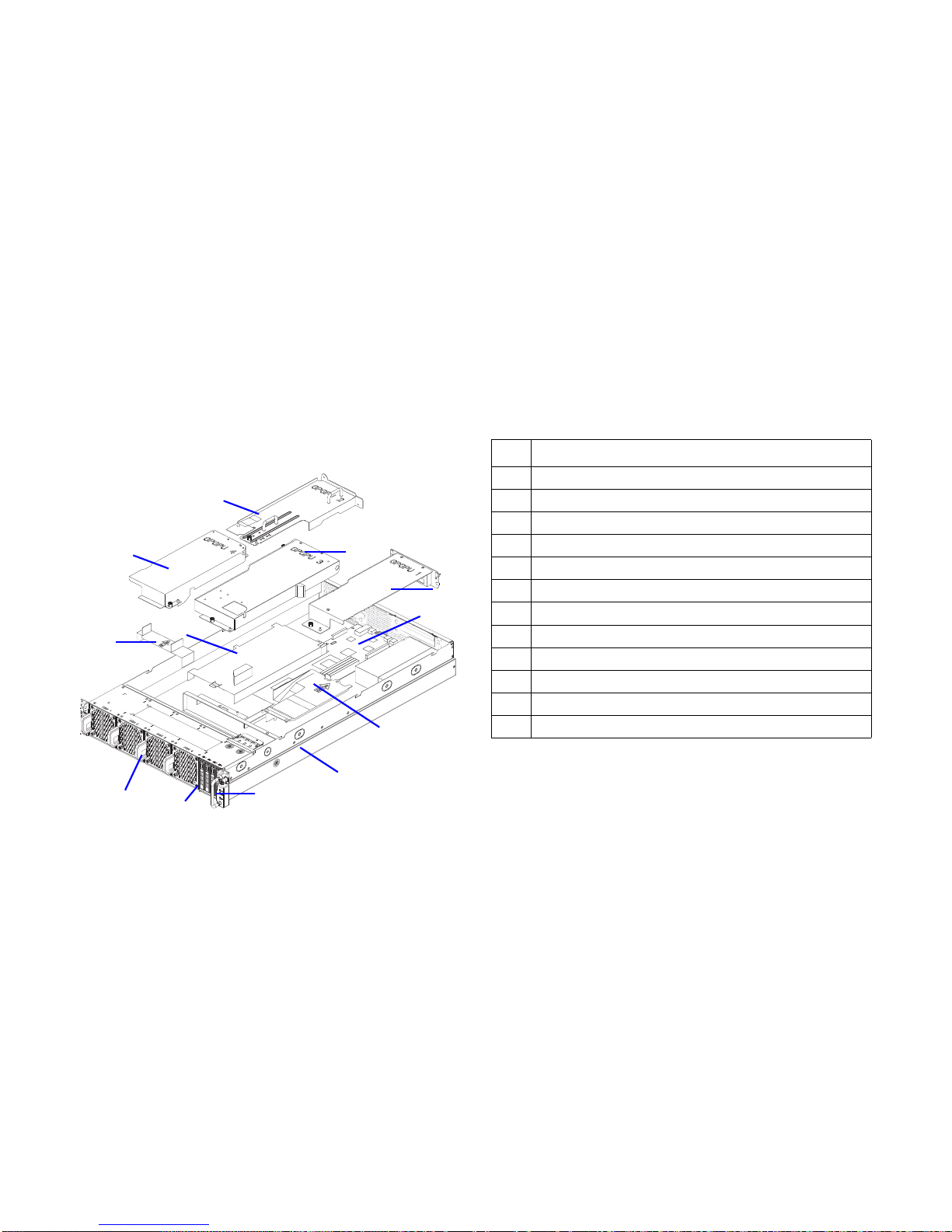
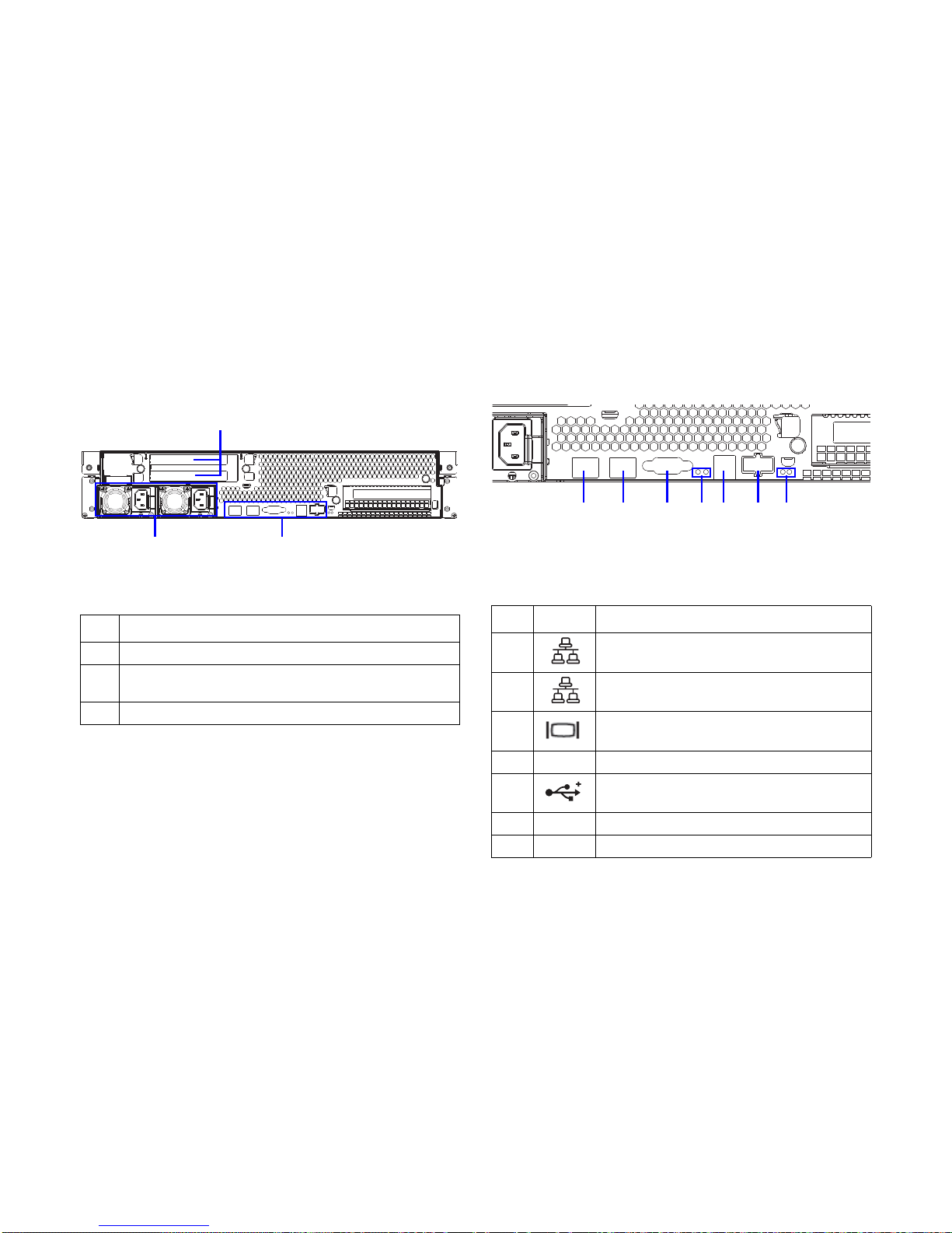
1.3. A Tour of the System
System Overview
System Component Overview
2
3
4
5
6
7
8
9
10
11
12
1
System Component Overview
NO.ITEM
1 General-purpose graphics processing unit (GPGPU)4
2 GPGPU2
3 GPGPU3
4 GPGPU1
5 Mainboard
6 Power distribution board (PDB) air duct
7Chassis
8 Control panel
9 Hot-swappable HDD (x4)
10 Fan module (x4)
11 GPGPU3 air duct
12 Mainboard air duct
Page 28
ABOUT THE SERVER SYSTEM FRONT VIEW
1-5
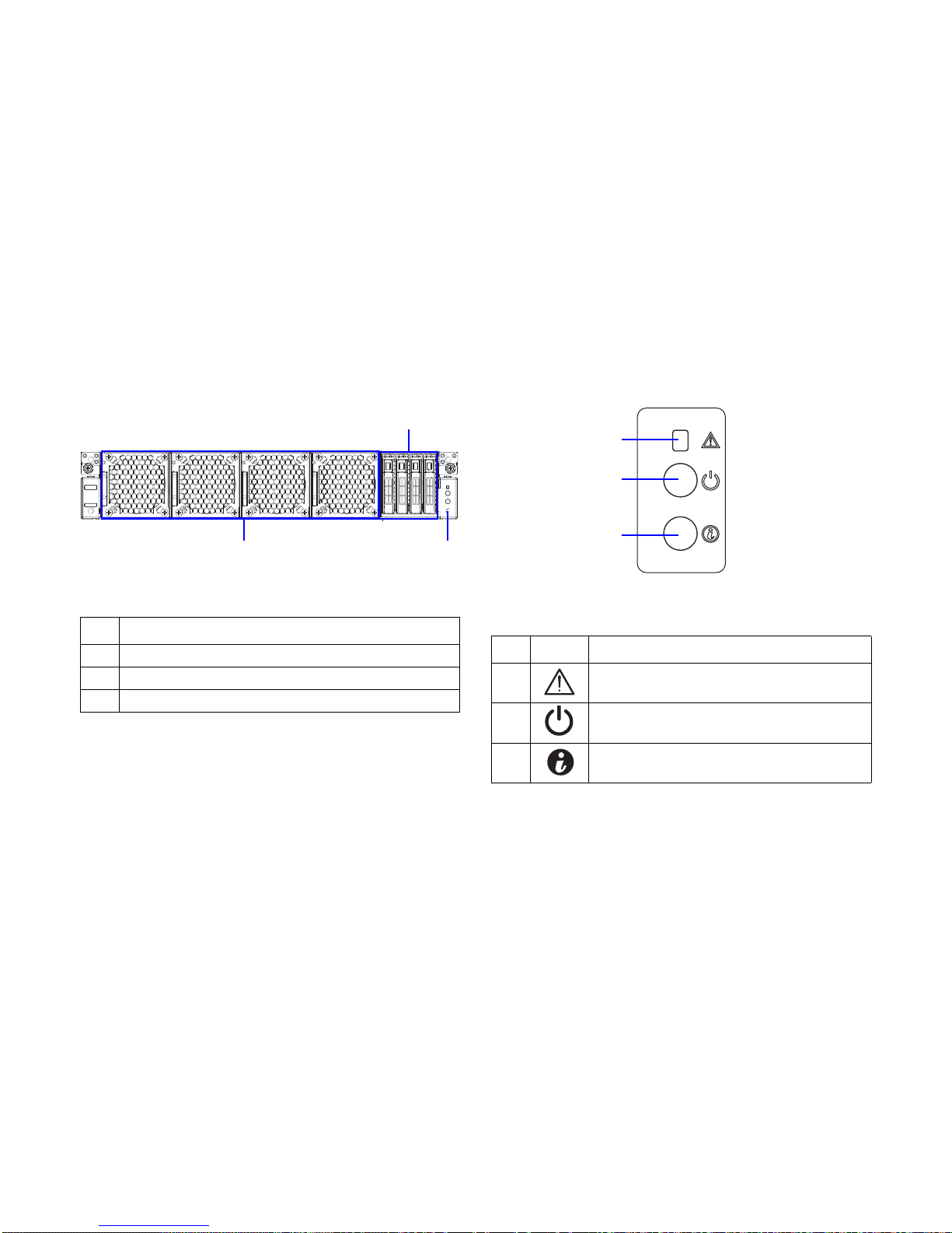
System Front View
System Front View
Control Panel
Control Panel
System Front View
NO.ITEM
1 Hot-swappable hard disk drives (x4)
2 Front panel
3 Fan module (x4)
1
2
3
Control Panel
NO.ICON ITEM
1 Fault/ status LED
2 Power/ sleep button with LED
3 ID button with LED
1
2
3
Page 29
ABOUT THE SERVER SYSTEM REAR VIEW
1-6
System Rear View
System Rear View
I/O Ports on Rear Panel
Mainboard I/O Ports
System Rear View
NO.ITEM
1 The venting holes for GPU1
2
I/O ports
NOTE: See I/O Ports on Rear Panel.
3 Power supply unit (x2)
1
2
3
Mainboard I/O Ports
NO.ICON ITEM
1 NIC1 LAN port
2 NIC2 LAN port
3VGA port
4 ID LED/ status LED
5 USB 2.0 port (x2)
6 IB port
7 IB act/link LED
12 34567
Page 30
ABOUT THE SERVER LED STATUS DEFINITIONS
1-7
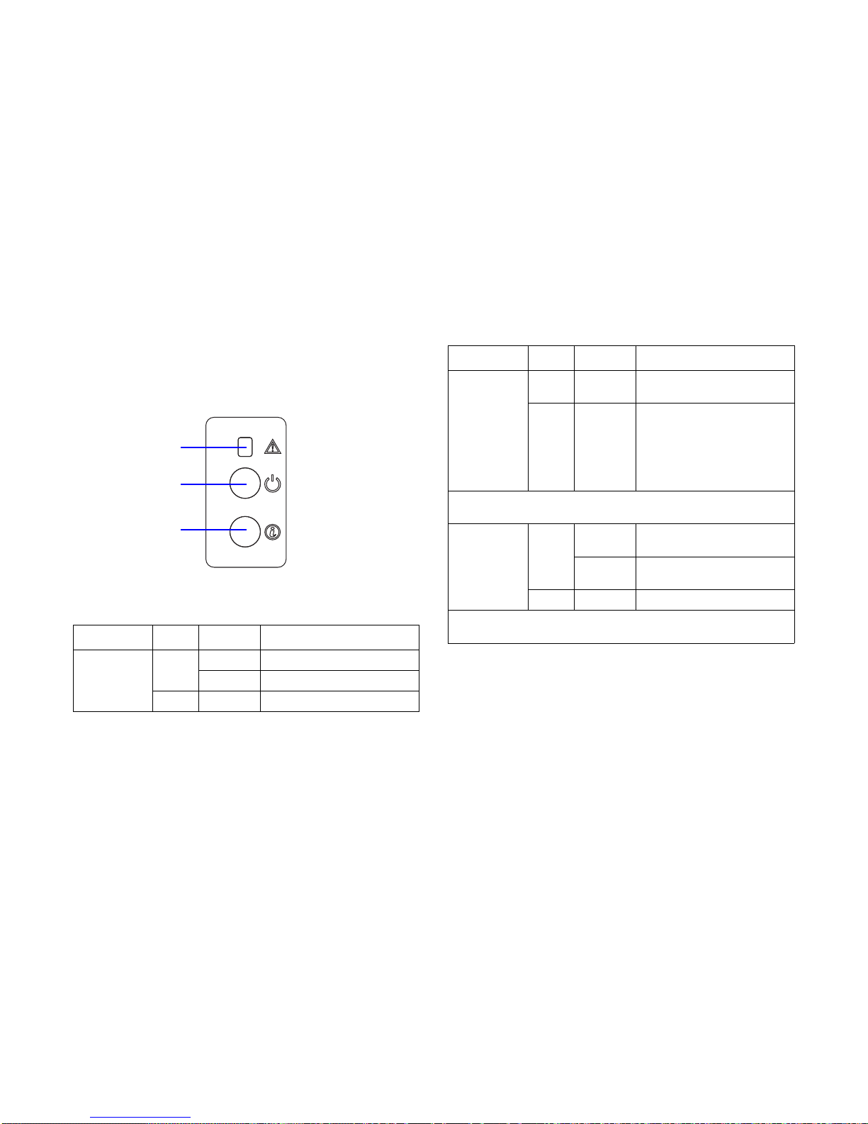
LED Status Definitions
Front Control Panel
Front Panel LED
Front Panel LED
LED COLOR CONDITION DESCRIPTION
Power/ sleep
Green
On Power on
Blink S1 sleep
-- Off Off
Fault/ status LED
Power/ sleep LED
Chassis ID LED
Fault/ Status
Amber Blink
System health error, reported by
BMC
-- Off
AC power off: system pow-
ered off
AC power on: system pow-
ered off and is in standby, no
prior degraded/non-critical/
critical state
NOTE: The status LED DS3A2 behavior is identical with the status LED
behavior on front panel.
Chassis ID
Blue
On
ID link via software, WebUI, or
ID button
Blink
Identification by software or
WebUI
-- Off No identification
NOTE:The ID LED DS3A1 behavior is identical with the ID LED behavior
on front panel.
Front Panel LED (Continued)
LED COLOR CONDITION DESCRIPTION
Page 31

ABOUT THE SERVER LED STATUS DEFINITIONS
1-8
Amber Blinking Identification LAN LED
The system mainboard has one I350 Ethernet controller and
two 1GbE ports. Each RJ45 connector has two built-in LEDs.
See the following illustration and table for details.
RJ45 LAN Connector
Amber Blinking Identification
NO SENSOR ACTION
1 Temperature sensor Non-critical / critical event asserted
2 Fan sensors Non-critical / critical event asserted
3 Voltage sensors State asserted
4 Power supply State asserted
5 Processor Thermal trip
6
Event logging disabled
1. SEL almost full
2. SEL full
7 Post error System firmware error
8Memory
1. Correctable ECC error
2. Uncorrectable ECC error
3. Correctable ECC error logging limit
reached
9 PCIe bus
1. Bus correctable error
2. Bus uncorrectable error
3. Bus fatal error
10 Watchdog 2
1. Timer expired
2. Hard reset
3. Power down
4. Power cycle
RJ45 LED Description
LED STATUS DESCRIPTION
Link LED
Off No link
Green Link
Blinking Link with access
Speed LED
Off 10 Mb
Amber 100 Mb
Green 1 Gb
Activity
Link
PIN 1
Location
Page 32

ABOUT THE SERVER LED STATUS DEFINITIONS
1-9
HDD LED
HDD LED
HDD LED
HDD STATE ACTIVITY LED
S
TATUS
LED
F
AIL LED
Slot empty Off Off Off
Drive online
Blinking when
activity
On Off
Drive rebuilding
Blinking when
activity
On 400
msec
Off 100
msec
Off
Drive failed Off Off
On 150 msec
Off 150 msec
Front
Activity LED
Status/ fail LED
Page 33

Installing Hardware
Chapter 2
Page 34

INSTALLING HARDWARE SAFETY MEASURES
2-1
2.1. Safety Measures
WARNING!
Always ask for assistance to move or lift the system.
WARNING!
Only perform troubleshooting as authorized by the product
documentation, or as directed by a service and support team.
Repairs not authorized by warranty may void the warranty
and damage the system.
WARNING!
Always make sure to disconnect the system from the AC electrical source. Powering down the system DOES NOT ensure
there is no electrical activity in the system.
WARNING!
Server components and circuit boards are easily damaged by
discharges of static electricity. Working on servers that are
connected to a power supply can be extremely dangerous.
Follow the guidelines below to avoid personal injury or damage to the server.
WARNING!
Always disconnect the server from the power outlet whenever
you are working inside the server case.
!
!
!
!
!
WARNING!
Wear a grounded wrist strap. If none are available, discharge
any personal static electricity by touching the bare metal
chassis of the server case, or the bare metal body of any
other grounded device.
WARNING!
Humid environments tend to have less static electricity than
dry environments. A grounding strap is warranted whenever
danger of static electricity exists.
WARNING!
Do not touch the components on the unless it is necessary to
do so. Do not flex or stress circuit boards.
WARNING!
Leave all replacement components inside their static-proof
packaging until you are ready to use them.
!
!
!
!
Page 35

INSTALLING HARDWARE HARD DISK DRIVE
2-2
2.2. Hard Disk Drive
Removing a Swappable HDD
Assembly
1. Press the tray handle button.
2. Pull the HDD tray handle open.
Removing HDD Assembly
3. Grasp the tray handle and pull the tray out of the system.
WARNING!
Do not operate the system without all hard drive trays inserted
into the chassis. All hard drive bays must be occupied by either
a hard drive or an empty hard drive tray. Hard drives may be
removed while the system is operational but should be immediately replaced by another hard drive or an empty hard drive
tray.
!
1
2
3
Page 36

INSTALLING HARDWARE INSTALLING A SWAPPABLE HDD ASSEMBLY
2-3
Installing a Swappable HDD
Assembly
1. Inser the HDD assembly into the system. Make sure hard
disk drive is fully inserted.
2. Push the tray handle closed.
Installing HDD Assembly
Removing an HDD Module
Prerequisite:
Remove the swappable HDD assembly. See
1. Remove the screw(s) securing the HDD module to the
HDD tray.
2. Remove the HDD module from the HDD tray.
Removing HDD Module
1
2
Page 37

INSTALLING HARDWARE INSTALLING AN HDD MODULE
2-4
Installing an HDD Module
1. Align the screw holes on HDD module with the screw
holes on the HDD tray, circuit board facing the HDD tray.
2. Install the HDD module into the HDD tray.
3. Secure the HDD module to the HDD tray with the
screw(s).
Installing HDD Module
Page 38

INSTALLING HARDWARE POWER SUPPLY UNIT
2-5
2.3. Power Supply Unit
Removing a PSU
1. Disconnect the power cord from the PSU.
2. Pull out the PSU handle.
3. Press the release latch.
4. Pull the PSU out of the system.
Removing PSU
Note:
Partial redundancy is supported on desigs with a throttling feature to downgrade power consumption when a PSU is faulty or
has been removed. A single faulty PSU can be replaced without
system shut down.
Note:
The redundant power supply unit can be replaced without shutting down the system.
CAUTION!
CAUTIONS APPEAR BEFORE THE TEXT IT REFERENCES, SIMILAR TO
NOTES AND WARNINGS. CAUTIONS, HOWEVER, APPEAR IN CAPITAL
LETTERS AND CONTAIN VITAL HEALTH AND SAFETY INFORMATION.
!
2
3
4
Page 39

INSTALLING HARDWARE INSTALLING A PSU
2-6
Installing a PSU
1. Insert the PSU into the system until flush with the chassis.
2. Pull down the PSU handle.
3. Connect the power cord into the PSU.
Installing PSU
1
2
Page 40

INSTALLING HARDWARE FAN
2-7
2.4. Fan
Removing a Swappable Fan
Assembly
1. Press the release latch.
2. Pull the fan assembly out of the system.
Removing Fan Assembly
Installing a Swappable Fan
Assembly
Prerequisite:
Remove the top cover. See Opening the Top Cover .
1
2
CAUTION!
IN CASE OF A ROTOR OR FAN FAILURE, REPLACE THE FAN MOD-
ULE.
TO AVOID SYSTEM OVERHEATING, INSTALL THE FAN MODULE
WITHIN 20 SECONDS.
!
Page 41

INSTALLING HARDWARE INSTALLING A SWAPPABLE FAN ASSEMBLY
2-8
Insert the fan assembly into the system until flush with the chassis.
Installing Fan Assembly
Page 42

INSTALLING HARDWARE TOP COVER
2-9
2.5. Top Cover
Removing a Top Cover
1. Press the release button (A) and slide the top cover.
2. Lift the top cover off the chassis.
Removing Top Cover
Installing a Top Cover
1. Place the top cover on the chassis.
2. Slide the top cover into place.
Installing Top Cover
A
Page 43

INSTALLING HARDWARE GENERAL-PURPOSE GRAPHICS PROCESSING UNITS
2-10
2.6. General-purpose Graphics Processing Units
GPGPU Location Overview
GPGPU Location Overview
Screw Tension Specification
When securing the screws to the GPGPU module, make sure
to follow the screw torque. See the information on illustrations
next to a corresponding screw.
Removing a GPGPU1 Module
The GPGPU1 module has three SKUs: M2075/M2090, Xeon
Phi™, K520/K10/K20/K20X.
Prerequisite:
Remove the top cover. See Opening the Top Cover .
1. Remove the screw(s) securing the GPGPU1 assembly to
the chassis.
GPGPU3
GPGPU2
GPGPU4
GPGPU1
WARNING!
Keep the dummy bracket installed together with the GPGPU
bracket even if no GPGPU or MIC presented.
!
Page 44

INSTALLING HARDWARE REMOVING A GPGPU1 MODULE
2-11
2. Release the GPGPU1 assembly from the tabs and standoff on the chassis.
Removing GPGPU1 Assembly
3. Remove the screw(s) securing the GPGPU1module to
the assembly.
4. Disconnect the GPGPU1 module from the GPGPU riser
card.
M2075/M2090 SKU:
Removing Screws (M2075/M2090)
Tab
Standoff
Page 45

INSTALLING HARDWARE REMOVING A GPGPU1 MODULE
2-12
K10/K20/K20X/K520 SKU:
Removing Screws (K10/K20/K20X/K520)
Xeon Phi™ SKU:
Removing Screws (Xeon Phi™)
5. Place the GPGPU1 assembly on the surface, board side
upwards.
6. Remove the screw(s) securing the GPGPU riser card to
the assembly.
Page 46

INSTALLING HARDWARE REMOVING A GPGPU1 MODULE
2-13
7. Remove the GPGPU riser card.
Removing GPGPU Riser Card
8. Remove the screw(s) securing the GPGPU1 module to
the assembly bracket(s).
9. Remove the bracket(s).
M2075/M2090 SKU:
Removing Screws (M2075/M2090)
Page 47

INSTALLING HARDWARE REMOVING A GPGPU1 MODULE
2-14
K520/K10/K20/K20X SKU:
Removing Screws (K520/K10/K20/K20X SKU)
Xeon Phi™ SKU:
Removing Screws (Xeon Phi™ SKU)
If the GPGPU module is not intended to install, to complete the
procedure, install a dummy bracket to the GPGPU bracket. See
Installing a GPGPU Dummy Bracket .
Page 48

INSTALLING HARDWARE INSTALLING A GPGPU1 MODULE
2-15
Installing a GPGPU1 Module
Prerequisite:
Remove the top cover. See Opening the Top Cover .
To install the GPGPU modue, make sure to remove the dummy
bracket from the GPGPU bracket if present. See Removing a
GPGPU Dummy Bracket .
1. Align the screw holes on the GPGPU riser card with the
screw holes on the GPGPU1 assembly bracket.
2. Secure the GPGPU riser card to the assembly with the
screw(s).
Installing GPGPU Riser Card
3. Align the screw holes on GPGPU1 assembly bracket with
the screw holes on the assembly.
4. Secure the brackets to the assembly with the screw(s).
CAUTION!
AVOID DAMAGING THE GPGPU MODULE. MAKE SURE NOT TO
OVER-LOAD THE SCREWS.
!
10~11 kg/cm
Page 49

INSTALLING HARDWARE INSTALLING A GPGPU1 MODULE
2-16
M2075/M2090 SKU:
Installing Screws (M2075/M2090)
K520/K10/K20/K20X SKU:
Installing Screws (K520/K10/K20/K20X)
5.0~5.5 kg/cm
6.6~7.2 kg/cm
5.0~5.5 kg/cm
Page 50

INSTALLING HARDWARE INSTALLING A GPGPU1 MODULE
2-17
Xeon Phi™ SKU:
Installing Screws (Xeon Phi™)
5. Align the screw holes on GPGPU1 module with the scew
holes on the assembly.
6. Connect the GPGPU1 module to the GPGPU riser card
on the assembly.
7. Secure the GPGPU1 module to the assembly with the
screw(s).
M2075/M2090 SKU:
Installing Screws (M2075/M2090)
CAUTION!
AVOID DAMAGING THE GPGPU MODULE. MAKE SURE NOT TO
OVER-LOAD THE SCREWS.
5.0~5.5 kg/cm
6.2~7.2 kg/cm
6.6~7.2 kg/cm
!
10~11 kg/cm
10~11 kg/cm
Page 51

INSTALLING HARDWARE INSTALLING A GPGPU1 MODULE
2-18
K10/K20/K20X/K520 SKU:
Installing Screws (K10/K20/K20X/K520)
Xeon Phi™ SKU:
Installing Screws (Xeon Phi™)
8. Flip the GPUGPU1 assembly
9. Align the screw and pin hole on the GPGPU1 assembly
with the screw hole and pin on the chassis.
10.Gently slide the front of the GPGPU1 assembly to the
tabs on the chassis.
11.Install the GPGPU1 assembly to the chassis.
10~11 kg/cm
6.6~7.2 kg/cm
10~11 kg/cm
10~11 kg/cm
Page 52

INSTALLING HARDWARE REMOVING A GPGPU2 MODULE
2-19
12.Secure the GPGPU1 assembly to the chassis with the
screw(s).
Installing GPGPU1 Assembly
Removing a GPGPU2 Module
The GPGPU2 module has three SKUs: M2075/M2090, Xeon
Phi™, K520/K10/K20/K20X.
Prerequisite:
Remove the top cover. See Opening the Top Cover .
1. Remove the screw(s) securing the GPGPU2 assembly to
the chassis.
2. Release the GPGPU2 assembly from the tabs on the
chassis.
Removing GPGPU2 Assembly
3. Place the GPGPU2 assembly on the surface, board side
upwards.
4. Remove the screw(s) securing the GPGPU2 module to
the assembly.
WARNING!
Keep the dummy bracket installed together with the GPGPU
bracket even if no GPGPU or MIC presented.
Guide pin
Tab
!
Page 53

INSTALLING HARDWARE REMOVING A GPGPU2 MODULE
2-20
5. Disconnect the GPGPU2 module from the GPGPU riser
card.
M2075/M2090 SKU:
Removing Screws (M2075/M2090)
K10/K20/K20X/K520 SKU:
Removing Screws (K10/K20/K20X/K520)
Page 54

INSTALLING HARDWARE REMOVING A GPGPU2 MODULE
2-21
Xeon Phi™ SKU:
Removing Screws (Xeon Phi™)
6. Remove the screw(s) securing the GPGPU riser card to
the assembly.
7. Remove the GPGPU riser card.
Removing GPGPU Riser Card
8. Remove the screw(s) securing the support bracket to the
assembly.
9. Remove the support bracket from the assembly.
Removing Support Bracket
Page 55

INSTALLING HARDWARE REMOVING A GPGPU2 MODULE
2-22
10.Remove the screw(s) securing the GPGPU2 module to
the assembly bracket(s).
11.Remove the bracket(s).
M2075/M2090 SKU:
Removing Screws (M2075/M2090)
K520/K10/K20/K20X SKU:
Removing Screws (K520/K10/K20/K20X)
Page 56

INSTALLING HARDWARE INSTALLING A GPGPU2 MODULE
2-23
Xeon Phi™ SKU:
Removing Screws (Xeon Phi™)
If the GPGPU module is not intended to install, to complete the
procedure, install a dummy bracket to the GPGPU bracket. See
Installing a GPGPU Dummy Bracket .
Installing a GPGPU2 Module
Prerequisite:
Remove the top cover. See Opening the Top Cover .
To install the GPGPU modue, make sure to remove the dummy
bracket from the GPGPU bracket if present. See Removing a
GPGPU Dummy Bracket .
1. Align the screw holes on the support bracket with the
screw holes on the GPGPU2 assembly.
2. Secure the support bracket to the assembly with the
screw(s).
Installing Support Bracket
3. Align the screw holes on the GPGPU riser card with the
screw holes on the GPGPU2 assembly bracket.
4. Secure the GPGPU riser card to the assembly with the
screw(s).
CAUTION!
AVOID DAMAGING THE GPGPU MODULE. MAKE SURE NOT TO
OVER-LOAD THE SCREWS.
CAUTION!
AVOID DAMAGING THE GPGPU MODULE. MAKE SURE NOT TO
OVER-LOAD THE SCREWS.
!
10~11 kg/cm
!
Page 57

INSTALLING HARDWARE INSTALLING A GPGPU2 MODULE
2-24
Installing GPGPU Riser Card
5. Align the screw holes on GPGPU2 assembly bracket with
the screw holes on the assembly.
6. Secure the brackets to the assembly with the screw(s).
M2075/M2090 SKU:
Installing Screws (M2075/M2090)
10~11 kg/cm
5.0~5.5 kg/cm
Page 58

INSTALLING HARDWARE INSTALLING A GPGPU2 MODULE
2-25
K520/K10/K20/K20X SKU:
Installing Screws (K520/K10/K20/K20X)
Xeon Phi™ SKU:
Installing Screws (Xeon Phi™)
7. Align the screw holes on GPGPU2 module with the scew
holes on the assembly.
8. Connect the GPGPU2 module to the GPGPU riser card
on the assembly.
9. Secure the GPGPU2 module to the assembly with the
screw(s).
5.0~5.5 kg/cm
6.6~7.2 kg/cm
6.6~7.2 kg/cm
6.6~7.2 kg/cm
6.6~7.2 kg/cm
Page 59

INSTALLING HARDWARE INSTALLING A GPGPU2 MODULE
2-26
M2075/M2090 SKU:
Installing Screws (M2075/M2090)
K10/K20/K20X/K520 SKU:
Installing Screws (K10/K20/K20X/K520)
10~11 kg/cm
6.6~7.2 kg/cm
10~11 kg/cm
6.6~7.2 kg/cm
Page 60

INSTALLING HARDWARE INSTALLING A GPGPU2 MODULE
2-27
Xeon Phi™ SKU:
Installing Screws (Xeon Phi™)
10.Flip the GPUGPU1 assembly
11.Align the screw and pin hole on the GPGPU2 assembly
with the screw hole and pin on the chassis.
12.Gently slide the front of the GPGPU2 assembly to the
tabs on the chassis.
13.Install the GPGPU2 assembly to the chassis.
14.Secure the GPGPU2 assembly to the chassis with the
screw(s).
Installing GPGPU2 Assembly
10~11 kg/cm
Tab
Guide pin
Page 61

INSTALLING HARDWARE REMOVING A GPGPU3 MODULE
2-28
Removing a GPGPU3 Module
The GPGPU3 module has three SKUs: M2075/M2090, Xeon
Phi™, K520/K10/K20/K20X.
Prerequisite:
Remove the top cover. See Opening the Top Cover .
1. Remove the screw(s) securing the GPGPU3 assembly to
the chassis.
2. Release the GPGPU3 assembly from the tabs on the
chassis.
Removing GPGPU3 Assembly
3. Remove the screw(s) securing the GPGPU3 module to
the assembly.
4. Disconnect the GPGPU3 module from the GPGPU riser
card.
WARNING!
Keep the dummy bracket installed together with the GPGPU
bracket even if no GPGPU or MIC presented.
!
Page 62

INSTALLING HARDWARE REMOVING A GPGPU3 MODULE
2-29
M2075/M2090 SKU:
Removing Screws (M2075/M2090)
K520/K10/K20/K20X SKU:
Removing Screws (K520/K10/K20/K20X)
Page 63

INSTALLING HARDWARE REMOVING A GPGPU3 MODULE
2-30
Xeon Phi™ SKU:
Removing Screws (Xeon Phi™)
5. Place the GPGPU3 assembly on the surface, board side
upwards.
6. Remove the screw(s) securing the GPGPU riser card to
the assembly.
7. Remove the GPGPU riser card.
Removing GPGPU Riser Card
8. Remove the screw(s) securing the GPGPU3 module to
the assembly bracket(s).
9. Remove the bracket(s).
Page 64

INSTALLING HARDWARE REMOVING A GPGPU3 MODULE
2-31
M2075/M2090 SKU:
Removing Screws (M2075/M2090)
K10/K20/K20X SKU:
Removing Screws (K10/K20/K20X)
Page 65

INSTALLING HARDWARE REMOVING A GPGPU3 MODULE
2-32
K520 SKU:
Removing Screws (K520)
Xeon Phi™ SKU:
Removing Screws (Xeon Phi™)
If the GPGPU module is not intended to install, to complete the
procedure, install a dummy bracket to the GPGPU bracket.
Installing a GPGPU Dummy Bracket .
Page 66

INSTALLING HARDWARE INSTALLING A GPGPU3 MODULE
2-33
Installing a GPGPU3 Module
Prerequisite:
Remove the top cover. See Opening the Top Cover .
To install the GPGPU modue, make sure to remove the dummy
bracket from the GPGPU bracket if present. See Removing a
GPGPU Dummy Bracket .
1. Align the screw holes on the GPGPU riser card with the
screw holes on the GPGPU3 assembly bracket.
2. Secure the GPGPU riser card to the assembly with the
screw(s).
Installing GPGPU Riser Card
3. Align the screw holes on GPGPU3 assembly bracket with
the screw holes on the assembly.
4. Secure the brackets to the assembly with the screw(s).
CAUTION!
AVOID DAMAGING THE GPGPU MODULE. MAKE SURE NOT TO
OVER-LOAD THE SCREWS.
!
10~11 kg/cm
Page 67

INSTALLING HARDWARE INSTALLING A GPGPU3 MODULE
2-34
M2075/M2090 SKU:
Installing Screws (M2075/M2090)
K10/K20/K20X SKU:
Installing Screws (K520/K10/K20/K20X)
6.6~7.2 kg/cm
5.0~5.5 kg/cm
6.6~7.2 kg/cm
5.0~5.5 kg/cm
Page 68

INSTALLING HARDWARE INSTALLING A GPGPU3 MODULE
2-35
K520 SKU:
Installing Screws (K520)
Xeon Phi™ SKU:
Installing Screws (Xeon Phi™)
5. Align the screw holes on GPGPU3 module with the scew
holes on the assembly.
6. Connect the GPGPU3 module to the GPGPU riser card
on the assembly.
7. Secure the GPGPU3 module to the assembly with the
screw(s).
6.6~7.2 kg/cm
5.0~5.5 kg/cm
CAUTION!
AVOID DAMAGING THE GPGPU MODULE. MAKE SURE NOT TO
OVER-LOAD THE SCREWS.
6.6~7.2 kg/cm
6.6~7.2 kg/cm
5.0~5.5 kg/cm
!
Page 69

INSTALLING HARDWARE INSTALLING A GPGPU3 MODULE
2-36
M2075/M2090 SKU:
Installing Screws (M2075/M2090)
K520/K10/K20/K20X SKU:
Installing Screws (K520/K10/K20/K20X)
10~11 kg/cm
10~11 kg/cm
10~11 kg/cm
10~11 kg/cm
Page 70

INSTALLING HARDWARE INSTALLING A GPGPU3 MODULE
2-37
Xeon Phi™ SKU:
Installing Screws (Xeon Phi™)
8. Flip the GPUGPU1 assembly
9. Align the screw and pin hole on the GPGPU3 assembly
with the screw hole and pin on the chassis.
10.Install the GPGPU3 assembly to the chassis.
11.Secure the GPGPU3 assembly to the chassis with the
screw(s).
Installing GPGPU3 Assembly
10~11 kg/cm
10~11 kg/cm
Guide pin
Page 71

INSTALLING HARDWARE REMOVING A GPGPU4 MODULE
2-38
Removing a GPGPU4 Module
The GPGPU4 module has three SKUs: M2075/M2090, Xeon
Phi™, K520/K10/K20/K20X.
Prerequisite:
Remove the top cover. See Opening the Top Cover .
1. Remove the screw(s) securing the GPGPU4 assembly to
the chassis.
2. Release the GPGPU4 assembly from the tabs on the
chassis.
Removing GPGPU4 Assembly
3. Place the GPGPU4 assembly on the surface, board side
upwards.
4. Remove the screw(s) securing the GPGPU4 module to
the assembly.
5. Disconnect the GPGPU4 module from the GPGPU riser
card.
WARNING!
Keep the dummy bracket installed together with the GPGPU
bracket even if no GPGPU or MIC presented.
!
Page 72

INSTALLING HARDWARE REMOVING A GPGPU4 MODULE
2-39
M2075/M2090 SKU:
Removing Screws (M2075/M2090)
K10/K20/K20X/K520 SKU:
Removing Screws (K10/K20/K20X/K520)
Page 73

INSTALLING HARDWARE REMOVING A GPGPU4 MODULE
2-40
Xeon Phi™ SKU:
Removing Screws (Xeon Phi™)
6. Remove the screw(s) securing the GPGPU4 module to
the assembly bracket(s).
7. Remove the bracket(s).
M2075/M2090 SKU:
Removing Screws (M2075/M2090)
Page 74

INSTALLING HARDWARE REMOVING A GPGPU4 MODULE
2-41
Xeon Phi™ SKU:
Removing Screws (Xeon Phi™)
8. Remove the screw(s) securing the GPGPU riser card to
the assembly.
9. Remove the GPGPU riser card.
Removing GPGPU Riser Card
If the GPGPU module is not intended to install, to complete the
procedure, install a dummy bracket to the GPGPU bracket.
Installing a GPGPU Dummy Bracket .
Page 75

INSTALLING HARDWARE INSTALLING A GPGPU4 MODULE
2-42
Installing a GPGPU4 Module
Prerequisite:
Remove the top cover. See Opening the Top Cover .
To install the GPGPU modue, make sure to remove the dummy
bracket from the GPGPU bracket if present. See Removing a
GPGPU Dummy Bracket .
1. Align the screw holes on the GPGPU riser card with the
screw holes on the GPGPU4 assembly bracket.
2. Secure the GPGPU riser card to the assembly with the
screw(s).
Installing GPGPU Riser Card
3. Align the screw holes on GPGPU4 assembly bracket with
the screw holes on the assembly.
4. Secure the brackets to the assembly with the screw(s).
CAUTION!
AVOID DAMAGING THE GPGPU MODULE. MAKE SURE NOT TO
OVER-LOAD THE SCREWS.
!
10~11 kg/cm
Page 76

INSTALLING HARDWARE INSTALLING A GPGPU4 MODULE
2-43
M2075/M2090 SKU:
Installing Screws (M2075/M2090)
Xeon Phi™ SKU:
Installing Screws (Xeon Phi™)
5. Align the screw holes on GPGPU4 module with the scew
holes on the assembly.
6. Connect the GPGPU4 module to the GPGPU riser card
on the assembly.
7. Secure the GPGPU4 module to the assembly with the
screw(s).
10~11 kg/cm
CAUTION!
AVOID DAMAGING THE GPGPU MODULE. MAKE SURE NOT TO
OVER-LOAD THE SCREWS.
6.6~7.2 kg/cm
6.6~7.2 kg/cm
6.6~7.2 kg/cm
6.6~7.2 kg/cm
!
Page 77

INSTALLING HARDWARE INSTALLING A GPGPU4 MODULE
2-44
M2075/M2090 SKU:
Installing Screws (M2075/M2090)
K10/K20/K20X/K520SKU:
Installing Screws (K10/K20/K20X/K520)
5.0~5.5 kg/cm
6.6~7.2 kg/cm
6.6~7.2 kg/cm
5.0~5.5 kg/cm
Page 78

INSTALLING HARDWARE INSTALLING A GPGPU4 MODULE
2-45
Xeon Phi™ SKU:
Installing Screws (Xeon Phi™)
8. Flip the GPUGPU1 assembly
9. Align the screw and pin hole on the GPGPU4 assembly
with the screw hole and pin on the chassis.
10.Install the GPGPU4 assembly to the chassis.
11.Secure the GPGPU4 assembly to the chassis with the
screw(s).
Installing GPGPU4 Assembly
5.0~5.5 kg/cm
10~11 kg/cm
Guide pin
Page 79

INSTALLING HARDWARE GPGPU DUMMY BRACKET
2-46
2.7. GPGPU Dummy Bracket
Each GPGPU has a specific dummy bracket.
Removing a GPGPU Dummy
Bracket
Prerequisite:
Install GPGPU1, GPGPU2, GPGPU3, GPGPU4. See
Installing a GPGPU1 Module, Installing a GPGPU2 Module, Installing a GPGPU3 Module, Installing a GPGPU4
Module.
1. Remove the screw(s) securing the dummy bracket to the
GPGPU bracket.
2. Remove the dummy bracket.
Removing GPGPU1 Dummy Bracket
Page 80

INSTALLING HARDWARE REMOVING A GPGPU DUMMY BRACKET
2-47
Removing GPGPU2 Dummy Bracket Removing GPGPU3 Dummy Bracket
Page 81

INSTALLING HARDWARE INSTALLING A GPGPU DUMMY BRACKET
2-48
Removing GPGPU4 Dummy Bracket
Installing a GPGPU Dummy
Bracket
Prerequisite:
Remove GPGPU1, GPGPU2, GPGPU3, GPGPU4. See
Removing a GPGPU1 Module, Removing a GPGPU2
Module, Removing a GPGPU3 Module, Removing a
GPGPU4 Module.
1. Align the screw holes on dummy bracket with the screw
holes on GPGPU bracket.
Page 82

INSTALLING HARDWARE INSTALLING A GPGPU DUMMY BRACKET
2-49
2. Secure the dummy bracket to the GPGPU bracket with
the screw(s).
Installing GPGPU1 Dummy Bracket
Installing GPGPU2 Dummy Bracket
Page 83

INSTALLING HARDWARE INSTALLING A GPGPU DUMMY BRACKET
2-50
Installing GPGPU3 Dummy Bracket Installing GPGPU4 Dummy Bracket
Page 84

INSTALLING HARDWARE AIR DUCT
2-51
2.8. Air Duct
Removing a Memory Air Duct
Prerequisite:
Remove the top cover. See Opening the Top Cover .
Remove the GPGPU3 assembly. See Removing a
GPGPU3 Module .
Remove the mainboard air duct. See Installing a Main-
board Air Duct .
1. Remove the right air duct.
2. Repeat for the additional DIMM air duct.
Removing DIMM Air Duct
CAUTION!
ENSURE ALL POWER IS DISCONNECTED FROM THE SYSTEM BEFORE PROCEEDING.
!
Left
Right
Page 85

INSTALLING HARDWARE INSTALLING A MEMORY AIR DUCT
2-52
Installing a Memory Air Duct
Prerequisite:
Install the DIMM modules. Installing a Memory Module .
1. Align the right air duct with the memory module slot
levers, tab on air duct facing the CPU socket on mainboard.
2. Install the air duct over the memory slot levers.
3. Repeat for the additional DIMM air duct.
Installing DIMM Air Duct
Removing a Mainboard Air Duct
Prerequisite:
Remove the GPGPU3. See Removing a GPGPU3 Module .
1. Press on the release tab to unlock the air duct and slide
the air duct towards the rear panel.
WARNING!
Air duct is needed for the proper cooling of the system. To prevent damage to the system, when installing the air duct, make
sure the arrow on top of the air duct is directing to the rear panel
of the mainboard module.
!
CAUTION!
ENSURE ALL POWER IS DISCONNECTED FROM THE SYSTEM BEFORE PROCEEDING.
Right
Left
Tab
DIMM slot lever
!
Page 86

INSTALLING HARDWARE INSTALLING A MAINBOARD AIR DUCT
2-53
2. Remove the air duct.
Removing Mainboard Air Duct
Installing a Mainboard Air Duct
Prerequisite:
Install the mainboard. See Installing a Mainboard Module
1. Align the air duct with the mainboard module, release tab
facing the slot on the chassis.
2. Install the air duct.
3. Slide the air duct until the release tab locks in place.
Installing Mainboard Air Duct
Removing a PDB Air Duct
Prerequisite:
Remove the top cover.
1. Use the release tab to unlock the air duct.
2. To remove the air duct, do the following:
Release the guide pins on the air duct from the slots on
the chassis.
CAUTION!
AVOID DAMAGING THE MAINBOARD MODULE.
Release tab
Rear
!
CAUTION!
ENSURE ALL POWER IS DISCONNECTED FROM THE SYSTEM BEFORE PROCEEDING.
3
Release tab
Slot
!
Page 87

INSTALLING HARDWARE INSTALLING A PDB AIR DUCT
2-54
Release the air duct from the guide pin on the chassis.
3. Remove the air duct.
Removing PDB Air Duct
Installing a PDB Air Duct
Prerequisite:
Install the PDB. See Installing a PDB .
1. Aling the PDB air duct over PDB assembly, release tab
facing the rear of the chassis.
2. Install the guide pins on air duct to the slots on the chassis and hole next to release tab to the guide pin on the
chassis.
Installing PDB Air Duct
Removing a GPGPU3 Air Duct
CAUTION!
AVOID DAMAGING THE PDB ASSEMBLY.
Release
tab
Guide pin on chassis
Guide pins on
air duct
!
CAUTION!
ENSURE ALL POWER IS DISCONNECTED FROM THE SYSTEM BEFORE PROCEEDING.
Release
tab
Guide pin on chassis
Guide pins on
air duct
Rear
!
Page 88

INSTALLING HARDWARE INSTALLING A GPGPU3 AIR DUCT
2-55
Prerequisite:
Remove the top cover. See Removing a Top Cover .
1. Remove the screw(s) securing the air duct to the chassis.
2. Remove the air duct.
Removing GPGPU3 Air Duct
Installing a GPGPU3 Air Duct
Prerequisite:
Install the GPGPU3 assembly. See Installing a GPGPU3
Module .
1. Align the screw hole on the air duct with the screw hole on
the chassis.
2. Install the air duct to the chassis.
3. Secure the air duct to the chassis with the screw(s).
Installing GPGPU3 Air Duct
CAUTION!
TO AVOID DAMAGE, DO NOT STRESS THE CABLE.
AVOID DAMAGING THE GPGPU MODULE. MAKE SURE NOT TO
OVER-LOAD THE SCREWS.
!
10~11 kg/cm
10~11 kg/cm
Page 89

INSTALLING HARDWARE MEMORY MODULES
2-56
2.9. Memory Modules
General Guidelines
Servers have specific rules for the population of memory on the
mainboards that must be obeyed. See the following server rules
for information on how to populate the particular server
required.
Memory Population Rules
Memory Channels
WARNING!
Mainboard is supplied with all DIMM slots populated with
dummy DIMMs for proper air flow. When installing and replacing memory modules, only remove those dummy DIMMs that
are to be directly replaced. All DIMM slots must be occupied at
all times by either a memory module or dummy DIMM.
!
CPU1
CPU0
C1
C2
D1
D2
G1
G2
H1
H2
B2
B1
A2
A1
F2
F1
E2
E1
Front
Page 90

INSTALLING HARDWARE REMOVING A MEMORY MODULE
2-57
Removing a Memory Module
Prerequisite:
Remove the top cover. Removing a Top Cover.
Remove the GPGPU3 assembly. See Removing a
GPGPU3 Module.
Remove the mainboard air-duct. See Removing a Main-
board Air Duct.
CPU 0 Memory Module Population Rules
DIMM SLOT
Q’
TY
A1 A2 B1 B2 C1 C2 D1 D2
1v
2
vv
vv
3
vvv
vvv
4
vvvv
vvvv
6 vvvvvv
8 vvvvvvvv
CPU 1 Memory Module Population Rules
DIMM SLOT
Q’
TY
E1 E2 F1 F2 G1 G2 H1 H2
1v
2
vv
vv
3vvv
4
vvvv
vvvv
6vvvvvv
8vvvvvvvv
CAUTION!
HANDLE THE MEMORY MODULE BY THE EDGES AT ALL TIMES.
WARNING!
Memory modules remain hot after the system is powered down.
Allow sufficient time for the memory modules to cool before
handling system components.
CPU 1 Memory Module Population Rules (Continued)
DIMM SLOT
Q’
TY
E1 E2 F1 F2 G1 G2 H1 H2
!
!
Page 91

INSTALLING HARDWARE INSTALLING A MEMORY MODULE
2-58
1. Press down on the two memory module slot levers (A).
The memory module partially ejects.
Removing Memory Module
2. Lift out the memory module.
Installing a Memory Module
Push the memory module firmly into the memory module slot.
The locking latches should automatically close over the edges
of the memory board when fully inserted into the slot.
Installing Memory Module
A
1
2
1
CAUTION!
HANDLE THE MEMORY MODULE BY THE EDGES AT ALL TIMES.
!
Page 92

INSTALLING HARDWARE MEMORY SUPPORT LIST
2-59
Memory Support List
UDIMM Support
RANKS PER DIMM
&
DATA WIDTH
MEMORY
CAPACITY PER
DIMM (GB)
1
SPEED (MT/S) & VOLTAGE
VALIDATED BY SLOT PER
CHANNEL (SPC) & DIMM PER
CHANNEL (DPC)
2,3
2 SLOTS PER CHANNEL
1DPC 2DPC
1.35V 1.5V
1.35
V
1.5V
SRx8 Non-ECC
1
b
2a4
a
n/a
1066,
1333
n/a
1066,
1333
DRx8 Non-ECC
2
b
4a8
a
n/a
1066,
1333
n/a
1066,
1333
SRx16 Non-ECC
512
b1b1b
n/a
1066,
1333
n/a
1066,
1333
SRx8 ECC
1
b
2a4
a
1066,
1333
1066,
1333
1066
1066,
1333
DRx8 ECC
2
b
4a8
a
1066,
1333
1066,
1333
1066
1066,
1333
Note:
1: Supported DRAM densities are 1 GB, 2 GB, and 4 GB. Only 2
GB and 4 GB are validated by Intel.
2: Command address timing is 1N for 1DPC and 2N for 2DPC
3: Romley-EP/EX platform does not support 3DPC when using
UDIMMs.
RDIMM Support
RANKS PER DIMM
&
DATA WIDTH
MEMORY
CAPACITY PER
DIMM (GB)
1
SPEED (MT/S) & VOLTAGE
VALIDATED BY SLOT PER CHANNEL
(
SPC) & DIMM PER CHANNEL
(
DPC)
2,3
2 SLOTS PER CHANNEL
1DPC 2DPC
1.35V 1.5V 1.35V 1.5V
SRx8
1
b2a4a
1066,
1333
1066,
1333,
1600
1066,
1333
1066,
1333,
1600
DRx8
2
b4a8a
1066,
1333
1066,
1333,
1600
1066,
1333
1066,
1333,
1600
DRx4
4
b8a
16
a
1066,
1333
1066,
1333,
1600
1066,
1333
1066,
1333,
1600
QRx4
8
b
16c32
c
800
800,
1066
800 800
Page 93

INSTALLING HARDWARE MEMORY SUPPORT LIST
2-60
QRx8
4
b8c
16
c
800
800,
1066
800 800
Note:
1: Supported DRAM densities are 1 GB, 2 GB, and 4 GB. Only 2
GB and 4 GB are validated by Intel.
2: Command address timing is 1N.
3: QR RDIMM are supported but only validated by Intel/PMO in a
homogenous environment. The coverage will have limited system
level testing, no signal integrity testing, and no interoperability
testing. The passing QR RDIMMs will be web posted.
RDIMM Support (Continued)
RANKS PER DIMM
&
DATA WIDTH
MEMORY
CAPACITY PER
DIMM (GB)
1
SPEED (MT/S) & VOLTAGE
VALIDATED BY SLOT PER CHANNEL
(
SPC) & DIMM PER CHANNEL
(
DPC)
2,3
2 SLOTS PER CHANNEL
1DPC 2DPC
1.35V 1.5V 1.35V 1.5V
Page 94

INSTALLING HARDWARE PROCESSOR HEAT SINKS
2-61
2.10. Processor Heat Sinks
Removing a Heat Sink
Prerequisite:
Remove the top cover. Removing a Top Cover .
Remove the GPGPU3 assembly. See Removing a
GPGPU3 Module .
Remove the mainboard air-duct. See Removing a Main-
board Air Duct .
1. Loosen the captive screw(s) securing the heat sink to the
mainboard.
Removing Heat Sink
2. Remove the heat sink.
3. Repeat for the additional heat sink.
Note:
S210-X2A2J system cooling capability can only support processor with 1U thermal profile requirement, cannot support processor with 2U thermal profile requirement.
WARNING!
The heatsink remains hot after the system has been powered
down. Allow sufficient time to cool before handling system components.
!
1
2
3
4
Page 95

INSTALLING HARDWARE INSTALLING A HEAT SINK
2-62
Installing a Heat Sink
1. Place the heat sink on the processor.
Installing Heat Sink
2. Secure the heat sink with the captive screw(s) in the order
shown.
3. Repeat for the additional heat sink.
1
2
3
4
Page 96

INSTALLING HARDWARE PROCESSORS
2-63
2.11. Processors
Removing a Processor
Prerequisite:
Remove the processor heat sink. See Removing a Heat
Sink.
1. Carefully press down and outwards on the right processor
locking lever to release it.
Release Right Processor Locking Lever
2. Carefully press down and outwards on the left processor
locking lever, pulling it fully open.
Release Left Processor Locking Lever
WARNING!
The processor remains hot after the system has been powered
down. Allow sufficient time to cool before handling system components.
!
Open 1st
Closed 1st
CAUTION!
DO NOT TRY TO FULLY OPEN THE LOCKING LEVERS TO PREVEN
DAMAGE TO THE SYSTEM.
CAUTION!
THE LOCKING LEVER IS HELD UNDER CONSIDERABLE FORCE AND
MAY SPRING UP UNEXPECTEDLY.
!
Open 1st
Closed 1st
!
Page 97

INSTALLING HARDWARE REMOVING A PROCESSOR
2-64
3. Press down on the right processor locking lever to lift the
processor cover part way and then lift the processor load
plate to the fully open position.
Opening Processor Cover
4. Lift the processor out of the socket.
Removing Processor
5. Repeat for the additional processor.
CAUTION!
AVOID CONTACT WITH ANY THERMAL GREASE ON THE PROCESSOR.
!
Page 98

INSTALLING HARDWARE INSTALLING A PROCESSOR
2-65
Installing a Processor
Prerequisite:
Install the processor heat sink. See Installing a Heat Sink.
1. Align the gold triangle identifying pin 1 of the processor
with the triangular cutout of the processor, and the
indents on processor with the tabs on socket.
Installing the Processor
2. Insert the processor into the socket, ensuring the four
keys on the socket fit into the corresponding keys on the
processor.
3. Lower the processor load plate over the processor.
Closing the Processor Cover
4. Push the left processor locking lever down and latch it
into the locked position.
5. Push the right processor locking lever down and latch it
into the locked position.
6. Repeat for the additional processor.
Indent
Pin 1
Tab
WARNING!
The processor should fit easily into the socket. Do not force the
processor in place.
Note:
Use the socket cover to protect the socket when the socket is
empty.
!
Open 1st
Closed 1st
3
4
5
Page 99

INSTALLING HARDWARE MAINBOARD MODULE
2-66
2.12. Mainboard Module
Removing a Mainboard Module
Prerequisite:
Disconnect all cables from the mainboard.
Remove the top cover. Removing a Top Cover .
Remove the GPGPU3 assembly. See Removing a
GPGPU3 Module .
Remove the mainboard air-duct. See Removing a Main-
board Air Duct .
Remove the DIMM air duct. See Removing a Memory Air
Duct .
Remove the DIMM modules. See Removing a Memory
Module .
Remove the processor heat sink. See Removing a Heat
Sink .
Remove the processor. See Removing a Processor .
1. Remove screw(s) securing the mainboard to the chassis.
Removing Screws
2. Lift the front end of the mainboard until free of the chassis
standoffs.
Page 100

INSTALLING HARDWARE INSTALLING A MAINBOARD MODULE
2-67
3. Lift mainboard at an angle to release the connectors from
the slots (A) on rear panel.
Removing Mainboard
4. Remove the mainboard from the chassis.
Installing a Mainboard Module
Prerequisite:
Remove the top cover. See Opening the Top Cover .
1. Align the mainboard with the standoffs on the chassis.
Installing Mainboard
2. Guide the connectors on mainboard to the slots on the
rear panel.
3. Install the mainboard.
 Loading...