

Page 1

STRATOS S210 Series
S210-X12MS
Two Socket High Performance &
Cost-Effective 1U Rackmount Server
Technical Guide
Date Modified: January 30, 2014 1:40 pm Document Version: 1.0.1
Page 2

TABLE OF CONTENTS
II
TABLE OF CONTENTS
About the Server
Introduction 1-1
System Features . . . . . . . . . . . . . . . . . . . . . . . . . . . . . . . . . . . . . . . . . . . . . . . . . . . . . . . . . . . . . . . . . . . . . .1-1
Package Contents . . . . . . . . . . . . . . . . . . . . . . . . . . . . . . . . . . . . . . . . . . . . . . . . . . . . . . . . . . . . . . . . . . . . .1-3
A Tour of the System 1-4
2.5” HDD System . . . . . . . . . . . . . . . . . . . . . . . . . . . . . . . . . . . . . . . . . . . . . . . . . . . . . . . . . . . . . . . . . . . . . .1-4
3.5” HDD System . . . . . . . . . . . . . . . . . . . . . . . . . . . . . . . . . . . . . . . . . . . . . . . . . . . . . . . . . . . . . . . . . . . . . .1-5
System Front Features . . . . . . . . . . . . . . . . . . . . . . . . . . . . . . . . . . . . . . . . . . . . . . . . . . . . . . . . . . . . . . . . .1-6
3.5” HDD SKU . . . . . . . . . . . . . . . . . . . . . . . . . . . . . . . . . . . . . . . . . . . . . . . . . . . . . . . . . . . . . . . . . . . . . .1-6
2.5” HDD SKU . . . . . . . . . . . . . . . . . . . . . . . . . . . . . . . . . . . . . . . . . . . . . . . . . . . . . . . . . . . . . . . . . . . . . .1-9
System HDD SKU Introduction . . . . . . . . . . . . . . . . . . . . . . . . . . . . . . . . . . . . . . . . . . . . . . . . . . . . . . . . . .1-12
2.5” HDD Configuration . . . . . . . . . . . . . . . . . . . . . . . . . . . . . . . . . . . . . . . . . . . . . . . . . . . . . . . . . . . . . .1-12
3.5” HDD Configuration . . . . . . . . . . . . . . . . . . . . . . . . . . . . . . . . . . . . . . . . . . . . . . . . . . . . . . . . . . . . . .1-12
System Rear Features . . . . . . . . . . . . . . . . . . . . . . . . . . . . . . . . . . . . . . . . . . . . . . . . . . . . . . . . . . . . . . . . .1-13
S210-X12MS System Rear View . . . . . . . . . . . . . . . . . . . . . . . . . . . . . . . . . . . . . . . . . . . . . . . . . . . . . . .1-13
S210-X12MS System I/O LED Description . . . . . . . . . . . . . . . . . . . . . . . . . . . . . . . . . . . . . . . . . . . . . . .1-14
Page 3

TABLE OF CONTENTS
III
Installing Hardware
Safety Measures 2-1
Top Cover 2-2
Opening the Top Cover . . . . . . . . . . . . . . . . . . . . . . . . . . . . . . . . . . . . . . . . . . . . . . . . . . . . . . . . . . . . . . . . .2-2
Closing the Top Cover . . . . . . . . . . . . . . . . . . . . . . . . . . . . . . . . . . . . . . . . . . . . . . . . . . . . . . . . . . . . . . . . . .2-3
Hard Disk Drives 2-4
Removing a 2.5” Hard Drive . . . . . . . . . . . . . . . . . . . . . . . . . . . . . . . . . . . . . . . . . . . . . . . . . . . . . . . . . . . . .2-4
Installing a 2.5” Hard Drive . . . . . . . . . . . . . . . . . . . . . . . . . . . . . . . . . . . . . . . . . . . . . . . . . . . . . . . . . . . . . .2-5
Removing a 3.5” Hard Disk Drive . . . . . . . . . . . . . . . . . . . . . . . . . . . . . . . . . . . . . . . . . . . . . . . . . . . . . . . . .2-6
Installing a 3.5” Hard Disk Drive . . . . . . . . . . . . . . . . . . . . . . . . . . . . . . . . . . . . . . . . . . . . . . . . . . . . . . . . . .2-8
Air Duct 2-9
Removing the Air Duct . . . . . . . . . . . . . . . . . . . . . . . . . . . . . . . . . . . . . . . . . . . . . . . . . . . . . . . . . . . . . . . . . .2-9
Installing the Air Duct . . . . . . . . . . . . . . . . . . . . . . . . . . . . . . . . . . . . . . . . . . . . . . . . . . . . . . . . . . . . . . . . . . .2-9
Fan Module Assembly 2-11
Removing the Fan Module Assembly . . . . . . . . . . . . . . . . . . . . . . . . . . . . . . . . . . . . . . . . . . . . . . . . . . . . .2-11
Installing the Fan Module Assembly . . . . . . . . . . . . . . . . . . . . . . . . . . . . . . . . . . . . . . . . . . . . . . . . . . . . . .2-12
Memory Modules 2-13
Page 4

TABLE OF CONTENTS
IV
General Guidelines . . . . . . . . . . . . . . . . . . . . . . . . . . . . . . . . . . . . . . . . . . . . . . . . . . . . . . . . . . . . . . . . . . .2-13
Removing Memory Modules . . . . . . . . . . . . . . . . . . . . . . . . . . . . . . . . . . . . . . . . . . . . . . . . . . . . . . . . . . . .2-13
Installing Memory Modules . . . . . . . . . . . . . . . . . . . . . . . . . . . . . . . . . . . . . . . . . . . . . . . . . . . . . . . . . . . . .2-14
Memory Population Rules . . . . . . . . . . . . . . . . . . . . . . . . . . . . . . . . . . . . . . . . . . . . . . . . . . . . . . . . . . . . . .2-15
Power Supply Unit 2-18
Removing a Power Supply Unit . . . . . . . . . . . . . . . . . . . . . . . . . . . . . . . . . . . . . . . . . . . . . . . . . . . . . . . . . .2-18
Installing a Power Supply Unit . . . . . . . . . . . . . . . . . . . . . . . . . . . . . . . . . . . . . . . . . . . . . . . . . . . . . . . . . . .2-19
Processor Heat Sinks 2-20
Removing a Heat Sink . . . . . . . . . . . . . . . . . . . . . . . . . . . . . . . . . . . . . . . . . . . . . . . . . . . . . . . . . . . . . . . . .2-20
Installing a Heat Sink . . . . . . . . . . . . . . . . . . . . . . . . . . . . . . . . . . . . . . . . . . . . . . . . . . . . . . . . . . . . . . . . . .2-20
Processors 2-22
Removing a Processor. . . . . . . . . . . . . . . . . . . . . . . . . . . . . . . . . . . . . . . . . . . . . . . . . . . . . . . . . . . . . . . . .2-22
Installing a Processor. . . . . . . . . . . . . . . . . . . . . . . . . . . . . . . . . . . . . . . . . . . . . . . . . . . . . . . . . . . . . . . . . .2-24
Mainboard Module 2-25
Removing a Mainboard Module . . . . . . . . . . . . . . . . . . . . . . . . . . . . . . . . . . . . . . . . . . . . . . . . . . . . . . . . . .2-25
Installing Mainboard Module . . . . . . . . . . . . . . . . . . . . . . . . . . . . . . . . . . . . . . . . . . . . . . . . . . . . . . . . . . . .2-26
PCI-E Riser Assembly 2-27
Page 5

TABLE OF CONTENTS
V
Removing PCI-E Riser Assembly . . . . . . . . . . . . . . . . . . . . . . . . . . . . . . . . . . . . . . . . . . . . . . . . . . . . . . . .2-27
Installing PCI-E Riser Assembly . . . . . . . . . . . . . . . . . . . . . . . . . . . . . . . . . . . . . . . . . . . . . . . . . . . . . . . . .2-28
PCI-E Card 2-29
Removing the PCI-E Card . . . . . . . . . . . . . . . . . . . . . . . . . . . . . . . . . . . . . . . . . . . . . . . . . . . . . . . . . . . . . .2-29
Installing the PCI-E Card . . . . . . . . . . . . . . . . . . . . . . . . . . . . . . . . . . . . . . . . . . . . . . . . . . . . . . . . . . . . . . .2-30
Expander Backplane 2-31
Removing the Expander Backplane. . . . . . . . . . . . . . . . . . . . . . . . . . . . . . . . . . . . . . . . . . . . . . . . . . . . . . .2-31
Installing the Expander Backplane. . . . . . . . . . . . . . . . . . . . . . . . . . . . . . . . . . . . . . . . . . . . . . . . . . . . . . . .2-33
HDD Backplane 2-35
Removing the HDD Backplane (2.5” SKU) . . . . . . . . . . . . . . . . . . . . . . . . . . . . . . . . . . . . . . . . . . . . . . . . .2-35
Installing the HDD Backplane (2.5” SKU) . . . . . . . . . . . . . . . . . . . . . . . . . . . . . . . . . . . . . . . . . . . . . . . . . .2-36
Removing the HDD Backplane (3.5” SKU) . . . . . . . . . . . . . . . . . . . . . . . . . . . . . . . . . . . . . . . . . . . . . . . . .2-37
Installing the HDD Backplane (3.5” SKU) . . . . . . . . . . . . . . . . . . . . . . . . . . . . . . . . . . . . . . . . . . . . . . . . . .2-39
BIOS
BIOS Setup Utility 3-1
Operation . . . . . . . . . . . . . . . . . . . . . . . . . . . . . . . . . . . . . . . . . . . . . . . . . . . . . . . . . . . . . . . . . . . . . . . . . . . .3-1
Setup Page Layout . . . . . . . . . . . . . . . . . . . . . . . . . . . . . . . . . . . . . . . . . . . . . . . . . . . . . . . . . . . . . . . . . . . .3-1
Page 6

TABLE OF CONTENTS
VI
Entering BIOS Setup . . . . . . . . . . . . . . . . . . . . . . . . . . . . . . . . . . . . . . . . . . . . . . . . . . . . . . . . . . . . . . . . . . .3-1
Keyboard Commands . . . . . . . . . . . . . . . . . . . . . . . . . . . . . . . . . . . . . . . . . . . . . . . . . . . . . . . . . . . . . . . . . .3-2
Menu Selection Bar . . . . . . . . . . . . . . . . . . . . . . . . . . . . . . . . . . . . . . . . . . . . . . . . . . . . . . . . . . . . . . . . . . . .3-4
Server Platform Setup Utility Screens . . . . . . . . . . . . . . . . . . . . . . . . . . . . . . . . . . . . . . . . . . . . . . . . . . . . . .3-4
Main Screen. . . . . . . . . . . . . . . . . . . . . . . . . . . . . . . . . . . . . . . . . . . . . . . . . . . . . . . . . . . . . . . . . . . . . . . . . .3-5
Advanced Screen. . . . . . . . . . . . . . . . . . . . . . . . . . . . . . . . . . . . . . . . . . . . . . . . . . . . . . . . . . . . . . . . . . . . . .3-6
PCI Screen . . . . . . . . . . . . . . . . . . . . . . . . . . . . . . . . . . . . . . . . . . . . . . . . . . . . . . . . . . . . . . . . . . . . . . . . .3-8
PCI Express Settings Screen . . . . . . . . . . . . . . . . . . . . . . . . . . . . . . . . . . . . . . . . . . . . . . . . . . . . . . . . . . .3-8
Trusted Computing Screen . . . . . . . . . . . . . . . . . . . . . . . . . . . . . . . . . . . . . . . . . . . . . . . . . . . . . . . . . . . .3-9
WHEA Configuration Screen . . . . . . . . . . . . . . . . . . . . . . . . . . . . . . . . . . . . . . . . . . . . . . . . . . . . . . . . . .3-10
CPU Configuration Screen . . . . . . . . . . . . . . . . . . . . . . . . . . . . . . . . . . . . . . . . . . . . . . . . . . . . . . . . . . . .3-11
Processor Information Screen . . . . . . . . . . . . . . . . . . . . . . . . . . . . . . . . . . . . . . . . . . . . . . . . . . . . . . . . .3-13
Runtime Error Logging Screen. . . . . . . . . . . . . . . . . . . . . . . . . . . . . . . . . . . . . . . . . . . . . . . . . . . . . . . . .3-15
SATA Controller Configuration Screen. . . . . . . . . . . . . . . . . . . . . . . . . . . . . . . . . . . . . . . . . . . . . . . . . . .3-16
SAS Configuration Screen . . . . . . . . . . . . . . . . . . . . . . . . . . . . . . . . . . . . . . . . . . . . . . . . . . . . . . . . . . . .3-17
Intel TXT (LT-SX) Configuration Screen . . . . . . . . . . . . . . . . . . . . . . . . . . . . . . . . . . . . . . . . . . . . . . . . .3-18
USB Configuration Screen . . . . . . . . . . . . . . . . . . . . . . . . . . . . . . . . . . . . . . . . . . . . . . . . . . . . . . . . . . . .3-19
Super I/O Configuration Screen . . . . . . . . . . . . . . . . . . . . . . . . . . . . . . . . . . . . . . . . . . . . . . . . . . . . . . . .3-20
Onboard Device Configuration Screen. . . . . . . . . . . . . . . . . . . . . . . . . . . . . . . . . . . . . . . . . . . . . . . . . . .3-21
Console Redirection Screen. . . . . . . . . . . . . . . . . . . . . . . . . . . . . . . . . . . . . . . . . . . . . . . . . . . . . . . . . . .3-23
Console Redirection Settings Screen. . . . . . . . . . . . . . . . . . . . . . . . . . . . . . . . . . . . . . . . . . . . . . . . . . . .3-24
Page 7

TABLE OF CONTENTS
VII
Chipset Screen . . . . . . . . . . . . . . . . . . . . . . . . . . . . . . . . . . . . . . . . . . . . . . . . . . . . . . . . . . . . . . . . . . . . . .3-26
North Bridge Screen. . . . . . . . . . . . . . . . . . . . . . . . . . . . . . . . . . . . . . . . . . . . . . . . . . . . . . . . . . . . . . . . .3-27
South Bridge Configuration Screen . . . . . . . . . . . . . . . . . . . . . . . . . . . . . . . . . . . . . . . . . . . . . . . . . . . . .3-30
ME Subsystem Screen. . . . . . . . . . . . . . . . . . . . . . . . . . . . . . . . . . . . . . . . . . . . . . . . . . . . . . . . . . . . . . .3-32
Server Management Screen . . . . . . . . . . . . . . . . . . . . . . . . . . . . . . . . . . . . . . . . . . . . . . . . . . . . . . . . . . . .3-33
System Event Log Screen . . . . . . . . . . . . . . . . . . . . . . . . . . . . . . . . . . . . . . . . . . . . . . . . . . . . . . . . . . . .3-35
FRU Information Screen. . . . . . . . . . . . . . . . . . . . . . . . . . . . . . . . . . . . . . . . . . . . . . . . . . . . . . . . . . . . . .3-36
BMC Network Configuration Screen . . . . . . . . . . . . . . . . . . . . . . . . . . . . . . . . . . . . . . . . . . . . . . . . . . . .3-38
Boot Option Screen . . . . . . . . . . . . . . . . . . . . . . . . . . . . . . . . . . . . . . . . . . . . . . . . . . . . . . . . . . . . . . . . . . .3-39
Boot Option Priorities Screen . . . . . . . . . . . . . . . . . . . . . . . . . . . . . . . . . . . . . . . . . . . . . . . . . . . . . . . . . .3-41
Security Screen . . . . . . . . . . . . . . . . . . . . . . . . . . . . . . . . . . . . . . . . . . . . . . . . . . . . . . . . . . . . . . . . . . . . . .3-41
Exit Screen . . . . . . . . . . . . . . . . . . . . . . . . . . . . . . . . . . . . . . . . . . . . . . . . . . . . . . . . . . . . . . . . . . . . . . . .3-42
Loading BIOS Defaults . . . . . . . . . . . . . . . . . . . . . . . . . . . . . . . . . . . . . . . . . . . . . . . . . . . . . . . . . . . . . . . .3-44
BIOS Update Utility 3-45
BIOS Update Utility . . . . . . . . . . . . . . . . . . . . . . . . . . . . . . . . . . . . . . . . . . . . . . . . . . . . . . . . . . . . . . . . . . .3-45
Recovery Mode . . . . . . . . . . . . . . . . . . . . . . . . . . . . . . . . . . . . . . . . . . . . . . . . . . . . . . . . . . . . . . . . . . . . . .3-45
Recovery Flow . . . . . . . . . . . . . . . . . . . . . . . . . . . . . . . . . . . . . . . . . . . . . . . . . . . . . . . . . . . . . . . . . . . . .3-45
Server Management 3-47
Page 8

TABLE OF CONTENTS
VIII
Console Redirection. . . . . . . . . . . . . . . . . . . . . . . . . . . . . . . . . . . . . . . . . . . . . . . . . . . . . . . . . . . . . . . . . . .3-47
Serial Configuration Settings . . . . . . . . . . . . . . . . . . . . . . . . . . . . . . . . . . . . . . . . . . . . . . . . . . . . . . . . . .3-47
Keystroke Mapping. . . . . . . . . . . . . . . . . . . . . . . . . . . . . . . . . . . . . . . . . . . . . . . . . . . . . . . . . . . . . . . . . .3-47
Limitations . . . . . . . . . . . . . . . . . . . . . . . . . . . . . . . . . . . . . . . . . . . . . . . . . . . . . . . . . . . . . . . . . . . . . . . .3-48
Interface to Server Management . . . . . . . . . . . . . . . . . . . . . . . . . . . . . . . . . . . . . . . . . . . . . . . . . . . . . . .3-48
PXE BIOS Support. . . . . . . . . . . . . . . . . . . . . . . . . . . . . . . . . . . . . . . . . . . . . . . . . . . . . . . . . . . . . . . . . . . .3-48
Checkpoints . . . . . . . . . . . . . . . . . . . . . . . . . . . . . . . . . . . . . . . . . . . . . . . . . . . . . . . . . . . . . . . . . . . . . . . . .3-48
Checkpoint Ranges . . . . . . . . . . . . . . . . . . . . . . . . . . . . . . . . . . . . . . . . . . . . . . . . . . . . . . . . . . . . . . . . .3-49
Standard Checkpoints . . . . . . . . . . . . . . . . . . . . . . . . . . . . . . . . . . . . . . . . . . . . . . . . . . . . . . . . . . . . . . .3-49
PEI Beep Codes. . . . . . . . . . . . . . . . . . . . . . . . . . . . . . . . . . . . . . . . . . . . . . . . . . . . . . . . . . . . . . . . . . . .3-52
DXE Phase. . . . . . . . . . . . . . . . . . . . . . . . . . . . . . . . . . . . . . . . . . . . . . . . . . . . . . . . . . . . . . . . . . . . . . . .3-52
DXE Beep Codes . . . . . . . . . . . . . . . . . . . . . . . . . . . . . . . . . . . . . . . . . . . . . . . . . . . . . . . . . . . . . . . . . . .3-55
ACPI/ASL Checkpoints . . . . . . . . . . . . . . . . . . . . . . . . . . . . . . . . . . . . . . . . . . . . . . . . . . . . . . . . . . . . . .3-55
Extra Checkpoint Ranges . . . . . . . . . . . . . . . . . . . . . . . . . . . . . . . . . . . . .
. . . . . . . . . . . . . . . . . . . . . . . . .3-56
BMC
Server Management Software 4-1
Introduction . . . . . . . . . . . . . . . . . . . . . . . . . . . . . . . . . . . . . . . . . . . . . . . . . . . . . . . . . . . . . . . . . . . . . . . . . .4-1
BMC Key Features and Functions . . . . . . . . . . . . . . . . . . . . . . . . . . . . . . . . . . . . . . . . . . . . . . . . . . . . . . . . .4-1
Power System . . . . . . . . . . . . . . . . . . . . . . . . . . . . . . . . . . . . . . . . . . . . . . . . . . . . . . . . . . . . . . . . . . . . . . . .4-1
Front Panel User Interface. . . . . . . . . . . . . . . . . . . . . . . . . . . . . . . . . . . . . . . . . . . . . . . . . . . . . . . . . . . . . . .4-1
Page 9

TABLE OF CONTENTS
IX
Power Button . . . . . . . . . . . . . . . . . . . . . . . . . . . . . . . . . . . . . . . . . . . . . . . . . . . . . . . . . . . . . . . . . . . . . . .4-1
ID Button . . . . . . . . . . . . . . . . . . . . . . . . . . . . . . . . . . . . . . . . . . . . . . . . . . . . . . . . . . . . . . . . . . . . . . . . . .4-1
LEDs. . . . . . . . . . . . . . . . . . . . . . . . . . . . . . . . . . . . . . . . . . . . . . . . . . . . . . . . . . . . . . . . . . . . . . . . . . . . . .4-2
LAN Interface . . . . . . . . . . . . . . . . . . . . . . . . . . . . . . . . . . . . . . . . . . . . . . . . . . . . . . . . . . . . . . . . . . . . . . . . .4-3
Session and User . . . . . . . . . . . . . . . . . . . . . . . . . . . . . . . . . . . . . . . . . . . . . . . . . . . . . . . . . . . . . . . . . . . .4-3
Serial Over LAN . . . . . . . . . . . . . . . . . . . . . . . . . . . . . . . . . . . . . . . . . . . . . . . . . . . . . . . . . . . . . . . . . . . . . . .4-3
Time Sync . . . . . . . . . . . . . . . . . . . . . . . . . . . . . . . . . . . . . . . . . . . . . . . . . . . . . . . . . . . . . . . . . . . . . . . . . . .4-3
SEL . . . . . . . . . . . . . . . . . . . . . . . . . . . . . . . . . . . . . . . . . . . . . . . . . . . . . . . . . . . . . . . . . . . . . . . . . . . . . . . .4-3
Platform Event . . . . . . . . . . . . . . . . . . . . . . . . . . . . . . . . . . . . . . . . . . . . . . . . . . . . . . . . . . . . . . . . . . . . . . . .4-4
Platform Event Filter. . . . . . . . . . . . . . . . . . . . . . . . . . . . . . . . . . . . . . . . . . . . . . . . . . . . . . . . . . . . . . . . . .4-4
BMC Firmware Update . . . . . . . . . . . . . . . . . . . . . . . . . . . . . . . . . . . . . . . . . . . . . . . . . . . . . . . . . . . . . . . . .4-4
DOS Recovery Utility . . . . . . . . . . . . . . . . . . . . . . . . . . . . . . . . . . . . . . . . . . . . . . . . . . . . . . . . . . . . . . . . .4-4
WebUI Update . . . . . . . . . . . . . . . . . . . . . . . . . . . . . . . . . . . . . . . . . . . . . . . . . . . . . . . . . . . . . . . . . . . . . .4-4
Page 10

TABLE OF CONTENTS
X
BMC Recovery 4-5
Recovery Process in DOS System . . . . . . . . . . . . . . . . . . . . . . . . . . . . . . . . . . . . . . . . . . . . . . . . . . . . . . .4-5
Recovery Process in Linux System . . . . . . . . . . . . . . . . . . . . . . . . . . . . . . . . . . . . . . . . . . . . . . . . . . . . . . .4-5
Recovery Process in Windows System . . . . . . . . . . . . . . . . . . . . . . . . . . . . . . . . . . . . . . . . . . . . . . . . . . . .4-5
Web Graphical User Interface (GUI) for ESMS 4-6
Using the Web GUI . . . . . . . . . . . . . . . . . . . . . . . . . . . . . . . . . . . . . . . . . . . . . . . . . . . . . . . . . . . . . . . . . . .4-6
Login . . . . . . . . . . . . . . . . . . . . . . . . . . . . . . . . . . . . . . . . . . . . . . . . . . . . . . . . . . . . . . . . . . . . . . . . . . . . . .4-6
Page 11

TABLE OF CONTENTS
XI
Dashboard . . . . . . . . . . . . . . . . . . . . . . . . . . . . . . . . . . . . . . . . . . . . . . . . . . . . . . . . . . . . . . . . . . . . . . . . . .4-7
Device Information . . . . . . . . . . . . . . . . . . . . . . . . . . . . . . . . . . . . . . . . . . . . . . . . . . . . . . . . . . . . . . . . . .4-8
Network Information . . . . . . . . . . . . . . . . . . . . . . . . . . . . . . . . . . . . . . . . . . . . . . . . . . . . . . . . . . . . . . . . .4-8
Sensor Monitoring . . . . . . . . . . . . . . . . . . . . . . . . . . . . . . . . . . . . . . . . . . . . . . . . . . . . . . . . . . . . . . . . . .4-9
Event Logs . . . . . . . . . . . . . . . . . . . . . . . . . . . . . . . . . . . . . . . . . . . . . . . . . . . . . . . . . . . . . . . . . . . . . . . .4-9
Server Information . . . . . . . . . . . . . . . . . . . . . . . . . . . . . . . . . . . . . . . . . . . . . . . . . . . . . . . . . . . . . . . . . . . .4-
0
FRU Information. . . . . . . . . . . . . . . . . . . . . . . . . . . . . . . . . . . . . . . . . . . . . . . . . . . . . . . . . . . . . . . . . . . . . .4-0
Server Component . . . . . . . . . . . . . . . . . . . . . . . . . . . . . . . . . . . . . . . . . . . . . . . . . . . . . . . . . . . . . . . . . .4-2
Server identify . . . . . . . . . . . . . . . . . . . . . . . . . . . . . . . . . . . . . . . . . . . . . . . . . . . . . . . . . . . . . . . . . . . . .4-3
Server Health Group . . . . . . . . . . . . . . . . . . . . . . . . . . . . . . . . . . . . . . . . . . . . . . . . . . . . . . . . . . . . . . . .4-4
Sensor Readings . . . . . . . . . . . . . . . . . . . . . . . . . . . . . . . . . . . . . . . . . . . . . . . . . . . . . . . . . . . . . . . . . . .4-4
Event Log . . . . . . . . . . . . . . . . . . . . . . . . . . . . . . . . . . . . . . . . . . . . . . . . . . . . . . . . . . . . . . . . . . . . . . . . .4-5
Configuration Group. . . . . . . . . . . . . . . . . . . . . . . . . . . . . . . . . . . . . . . . . . . . . . . . . . . . . . . . . . . . . . . . . . .4-7
Active Directory . . . . . . . . . . . . . . . . . . . . . . . . . . . . . . . . . . . . . . . . . . . . . . . . . . . . . . . . . . . . . . . . . . . .4-7
DNS . . . . . . . . . . . . . . . . . . . . . . . . . . . . . . . . . . . . . . . . . . . . . . . . . . . . . . . . . . . . . . . . . . . . . . . . . . . . .4-0
LDAP/E-Directory
. . . . . . . . . . . . . . . . . . . . . . . . . . . . . . . . . . . . . . . . . . . . . . . . . . . . . . . . . . . . . . . . . . .4-
2
Mouse Mode. . . . . . . . . . . . . . . . . . . . . . . . . . . . . . . . . . . . . . . . . . . . . . . . . . . . . . . . . . . . . . . . . . . . . . .4-5
Network . . . . . . . . . . . . . . . . . . . . . . . . . . . . . . . . . . . . . . . . . . . . . . . . . . . . . . . . . . . . . . . . . . . . . . . . . .4-6
PEF . . . . . . . . . . . . . . . . . . . . . . . . . . . . . . . . . . . . . . . . . . . . . . . . . . . . . . . . . . . . . . . . . . . . . . . . . . . . .4-8
RADIUS . . . . . . . . . . . . . . . . . . . . . . . . . . . . . . . . . . . . . . . . . . . . . . . . . . . . . . . . . . . . . . . . . . . . . . . . . .4-5
Remote Session . . . . . . . . . . . . . . . . . . . . . . . . . . . . . . . . . . . . . . . . . . . . . . . . . . . . . . . . . . . . . . . . . . . .4-6
Page 12

TABLE OF CONTENTS
XII
SMTP . . . . . . . . . . . . . . . . . . . . . . . . . . . . . . . . . . . . . . . . . . . . . . . . . . . . . . . . . . . . . . . . . . . . . . . . . . . .4-7
SOL . . . . . . . . . . . . . . . . . . . . . . . . . . . . . . . . . . . . . . . . . . . . . . . . . . . . . . . . . . . . . . . . . . . . . . . . . . . . .4-0
SSL. . . . . . . . . . . . . . . . . . . . . . . . . . . . . . . . . . . . . . . . . . . . . . . . . . . . . . . . . . . . . . . . . . . . . . . . . . . . . .4-0
User Management . . . . . . . . . . . . . . . . . . . . . . . . . . . . . . . . . . . . . . . . . . . . . . . . . . . . . . . . . . . . . . . . . .4-4
Virtual Media . . . . . . . . . . . . . . . . . . . . . . . . . . . . . . . . . . . . . . . . . . . . . . . . . . . . . . . . . . . . . . . . . . . . . .4-7
Remote Control
. . . . . . . . . . . . . . . . . . . . . . . . . . . . . . . . . . . . . . . . . . . . . . . . . . . . . . . . . . . . . . . . . . . . . .4-
8
Console Redirection . . . . . . . . . . . . . . . . . . . . . . . . . . . . . . . . . . . . . . . . . . . . . . . . . . . . . . . . . . . . . . . . .4-8
Server Power Control . . . . . . . . . . . . . . . . . . . . . . . . . . . . . . . . . . . . . . . . . . . . . . . . . . . . . . . . . . . . . . . .4-5
Maintenance Group . . . . . . . . . . . . . . . . . . . . . . . . . . . . . . . . . . . . . . . . . . . . . . . . . . . . . . . . . . . . . . . . . . .4-6
Firmware Update . . . . . . . . . . . . . . . . . . . . . . . . . . . . . . . . . . . . . . . . . . . . . . . . . . . . . . . . . . . . . . . . . . .4-6
Preserve Configuration. . . . . . . . . . . . . . . . . . . . . . . . . . . . . . . . . . . . . . . . . . . . . . . . . . . . . . . . . . . . . . .4-7
Restore Factory Defaults . . . . . . . . . . . . . . . . . . . . . . . . . . . . . . . . . . . . . . . . . . . . . . . . . . . . . . . . . . . . .4-7
Log Out . . . . . . . . . . . . . . . . . . . . . . . . . . . . . . . . . . . . . . . . . . . . . . . . . . . . . . . . . . . . . . . . . . . . . . . . . . . .4-8
User Privilege. . . . . . . . . . . . . . . . . . . . . . . . . . . . . . . . . . . . . . . . . . . . . . . . . . . . . . . . . . . . . . . . . . . . . . . .4-8
Jumpers and Connectors
Mainboard Jumpers and Connectors 5-1
Connectors. . . . . . . . . . . . . . . . . . . . . . . . . . . . . . . . . . . . . . . . . . . . . . . . . . . . . . . . . . . . . . . . . . . . . . . . . . .5-1
Jumpers . . . . . . . . . . . . . . . . . . . . . . . . . . . . . . . . . . . . . . . . . . . . . . . . . . . . . . . . . . . . . . . . . . . . . . . . . . . . .5-2
Page 13

TABLE OF CONTENTS
XIII
Rail Kit Assembly
Rail Kit Assembly 6-1
Installing the Rack Brackets. . . . . . . . . . . . . . . . . . . . . . . . . . . . . . . . . . . . . . . . . . . . . . . . . . . . . . . . . . . . . .6-1
Preparing for the Installation . . . . . . . . . . . . . . . . . . . . . . . . . . . . . . . . . . . . . . . . . . . . . . . . . . . . . . . . . . .6-1
Installing the Inner Rail. . . . . . . . . . . . . . . . . . . . . . . . . . . . . . . . . . . . . . . . . . . . . . . . . . . . . . . . . . . . . . . .6-2
Installing the Outer Rail . . . . . . . . . . . . . . . . . . . . . . . . . . . . . . . . . . . . . . . . . . . . . . . . . . . . . . . . . . . . . . .6-3
Troubleshooting
Troubleshooting 7-1
Server Boot Issue Topics. . . . . . . . . . . . . . . . . . . . . . . . . . . . . . . . . . . . . . . . . . . . . . . . . . . . . . . . . . . . . . . .7-1
System does not Boot after Initial Installation . . . . . . . . . . . . . . . . . . . . . . . . . . . . . . . . . . . . . . . . . . . . . .7-1
System does not boot after Configuration Changes. . . . . . . . . . . . . . . . . . . . . . . . . . . . . . . . . . . . . . . . . .7-3
Installation and Assembly Safety Instructions
Installation and Assembly Safety Instructions 8-1
Guidelines . . . . . . . . . . . . . . . . . . . . . . . . . . . . . . . . . . . . . . . . . . . . . . . . . . . . . . . . . . . . . . . . . . . . . . . . . . .8-1
Page 14

TABLE OF CONTENTS
XIV
Safety Information
Server Safety Information 9-1
Safety Warnings and Cautions . . . . . . . . . . . . . . . . . . . . . . . . . . . . . . . . . . . . . . . . . . . . . . . . . . . . . . . . . . .9-1
Intended Application Uses . . . . . . . . . . . . . . . . . . . . . . . . . . . . . . . . . . . . . . . . . . . . . . . . . . . . . . . . . . . . . . .9-2
Site Selection . . . . . . . . . . . . . . . . . . . . . . . . . . . . . . . . . . . . . . . . . . . . . . . . . . . . . . . . . . . . . . . . . . . . . . . . .9-2
Equipment Handling Practices. . . . . . . . . . . . . . . . . . . . . . . . . . . . . . . . . . . . . . . . . . . . . . . . . . . . . . . . . . . .9-2
Power and Electrical Warnings . . . . . . . . . . . . . . . . . . . . . . . . . . . . . . . . . . . . . . . . . . . . . . . . . . . . . . . . . . .9-3
Power Cord Warnings . . . . . . . . . . . . . . . . . . . . . . . . . . . . . . . . . . . . . . . . . . . . . . . . . . . . . . . . . . . . . . . .9-3
System Access Warnings . . . . . . . . . . . . . . . . . . . . . . . . . . . . . . . . . . . . . . . . . . . . . . . . . . . . . . . . . . . . . . .9-4
Rack Mount Warnings . . . . . . . . . . . . . . . . . . . . . . . . . . . . . . . . . . . . . . . . . . . . . . . . . . . . . . . . . . . . . . . . . .9-5
Electrostatic Discharge (ESD) . . . . . . . . . . . . . . . . . . . . . . . . . . . . . . . . . . . . . . . . . . . . . . . . . . . . . . . . . . . .9-6
Other Hazards . . . . . . . . . . . . . . . . . . . . . . . . . . . . . . . . . . . . . . . . . . . . . . . . . . . . . . . . . . . . . . . . . . . . . . . .9-7
Battery Replacement . . . . . . . . . . . . . . . . . . . . . . . . . . . . . . . . . . . . . . . . . . . . . . . . . . . . . . . . . . . . . . . . .9-7
Cooling and Airflow . . . . . . . . . . . . . . . . . . . . . . . . . . . . . . . . . . . . . . . . . . . . . . . . . . . . . . . . . . . . . . . . . .9-7
Laser Peripherals or Devices . . . . . . . . . . . . . . . . . . . . . . . . . . . . . . . . . . . . . . . . . . . . . . . . . . . . . . . . . . .9-8
Regulatory and Compliance Information
Regulatory and Compliance Information 10-1
Product Regulatory Compliance Markings. . . . . . . . . . . . . . . . . . . . . . . . . . . . . . . . . . . . . . . . . . . . . . . . . .10-1
Page 15

TABLE OF CONTENTS
XV
Electromagnetic Compatibility Notices. . . . . . . . . . . . . . . . . . . . . . . . . . . . . . . . . . . . . . . . . . . . . . . . . . . . .10-3
FCC Verification Statement (USA) . . . . . . . . . . . . . . . . . . . . . . . . . . . . . . . . . . . . . . . . . . . . . . . . . . . . . .10-3
Europe (CE Declaration of Conformity) . . . . . . . . . . . . . . . . . . . . . . . . . . . . . . . . . . . . . . . . . . . . . . . . . .10-3
VCCI (Japan) . . . . . . . . . . . . . . . . . . . . . . . . . . . . . . . . . . . . . . . . . . . . . . . . . . . . . . . . . . . . . . . . . . . . . .10-4
BSMI (Taiwan) . . . . . . . . . . . . . . . . . . . . . . . . . . . . . . . . . . . . . . . . . . . . . . . . . . . . . . . . . . . . . . . . . . . . .10-4
KCC (Korea). . . . . . . . . . . . . . . . . . . . . . . . . . . . . . . . . . . . . . . . . . . . . . . . . . . . . . . . . . . . . . . . . . . . . . .10-4
Page 16
CONVENTIONS
XVI
Conventions
Several different typographic conventions are used throughout
this manual. Refer to the following examples for common
usage.
Bold type face denotes menu items, buttons and application
names.
Italic type face denotes references to other sections, and the
names of the folders, menus, programs, and files.
<Enter> type face denotes keyboard keys.
WARNING!
Warning information appears before the text it references and
should not be ignored as the content may prevent damage to the
device.
CAUTION!
CAUTIONS APPEAR BEFORE THE TEXT IT REFERENCES, SIMILAR TO
NOTES AND WARNINGS. CAUTIONS, HOWEVER, APPEAR IN CAPITAL
LETTERS AND CONTAIN VITAL HEALTH AND SAFETY INFORMATION.
Important:
Indicates information that is important to know for the proper
completion of a procedure, choice of an option, or completing a
task.
!
!
Note:
Highlights general or useful information and tips.
Page 17
ACRONYMS
XVII
Acronyms
TERM DEFINITION
A/D Analog to Digital
ACPI Advanced Configuration and Power Interface
ASF Alerting Standard Forum
Asserted
Active-high (positive true) signals are asserted when in
the high electrical state (near power potential). Activelow (negative true) signals are asserted when in the low
electrical state (near ground potential).
BIOS Basic Input/Output System
BIST Built-In Self Test
BMC
At the heart of the IPMI architecture is a microcontroller
called the Baseboard management controller (BMC)
Bridge
Circuitry connecting one computer bus to another,
allowing an agent on one to access the other
BSP Bootstrap processor
Byte 8-bit quantity
CLI Command Line Interface
CMOS
In terms of this specification, this describes the PC-AT
compatible region of battery-backed 128 bytes of
memory, which normally resides on the baseboard
CPU Central Processing Unit
Deasserted
A signal is deasserted when in the inactive state. Activelow signal names have “_L” appended to the end of the
signal mnemonic. Active-high signal names have no “_L”
suffix. To reduce confusion when referring to active-high
and active-low signals, the terms one/zero, high/low, and
true/false are not used when describing signal states.
DTC Data Transfer Controller
EEPROM Electrically Erasable Programmable Read-Only Memory
EMP Emergency Management Port
FRU Field Replaceable Unit
GB 1024 MB.
GPIO General Purpose Input/Out
HSC Hot-Swap Controller
Hz Hertz (1 cycle/second)
I
2
C
Inter-Integrated Circuit bus
IANA Internet Assigned Numbers Authority
IBF Input buffer
ICH I/O Controller Hub
ICMB Intelligent Chassis Management Bus
IERR Internal Error
IP Internet Protocol
IPMB Intelligent Platform Management Bus
Page 18
ACRONYMS
XVIII
IPMI Intelligent Platform Management Interface
ITP In-Target Probe
KB 1024 bytes.
KCS Keyboard Controller Style
KVM Keyboard, Video, Mouse
LAN Local Area Network
LCD Liquid Crystal Display
LCT Lower Critical Threshold
LED Light Emitting Diode
LNCT Lower Non-Critical Threshold
LNRT Lower Non-Recoverable Threshold
LPC Low Pin Count
LSI Large Scale Integration
LUN Logical Unit Number
MAC Media Access Control
MB 1024 KB
MD2 Message Digest 2 – Hashing Algorithm
MD5 Message Digest 5 – Hashing Algorithm – Higher Security
Ms Milliseconds
Mux Multiplexer
NIC Network Interface Card
NMI Nonmaskable Interrupt
NM Node Management
OBF Output buffer
OEM Original Equipment Manufacturer
Ohm Unit of electrical resistance
PDB Power Distribution Board
PEF Platform Event Filtering
PEP Platform Event Paging
PERR Parity Error
POH Power-On Hours
POST Power-On Self Test
PWM Pulse Width Modulation
RAC Remote Access Card
RAM Random Access Memory
RMCP Remote Management Control Protocol
ROM Read Only Memory
RTC
Real-Time Clock. Component of the chipset on the
baseboard.
RTOS Real Time Operation System
SCI Serial Communication Interface
SDC SCSI Daughter Card
SDR Sensor Data Record
SEEPROM
Serial Electrically Erasable Programmable Read-Only
Memory
Page 19
ACRONYMS
XIX
SEL System Event Log
SERR System Error
SMBus
A two-wire interface based on the I
2
C protocol. The
SMBus is a low-speed bus that provides positive
addressing for devices, as well as bus arbitration
SMI
Server Management Interrupt. SMI is the highest priority
nonmaskable interrupt
SMM Server Management Mode
SMS Server Management Software
SNMP Simple Network Management Protocol
SOL Serial Over LAN
UART Universal Asynchronous Receiver/Transmitter
UCT Upper Critical Threshold
UDP User Datagram Protocol
UNCT Upper Non-Critical Threshold
UNRT Upper Non-Recoverable Threshold
WDT Watchdog Timer
Word 16-bit quantity
Page 20

REVISION HISTORY
XX
Revision History
Refer to the table below for the updates made to this manual.
Copyright
Copyright © 2014 Quanta Computer Inc. This publication,
including all photographs, illustrations and software, is
protected under international copyright laws, with all rights
reserved. Neither this manual, nor any of the material contained
herein, may be reproduced without the express written consent
of the manufacturer. All trademarks and logos are copyrights of
their respective owners.
Version 1.0.1 / January, 2014
Disclaimer
The information in this document is subject to change without
notice. The manufacturer makes no representations or
warranties with respect to the contents hereof and specifically
disclaims any implied warranties of merchantability or fitness for
any particular purpose. Furthermore, the manufacturer reserves
the right to revise this publication and to make changes from
time to time in the content hereof without obligation of the
manufacturer to notify any person of such revision or changes.
For the latest information and updates please refer to
www.quantaqct.com
All the illustrations in this technical guide are for reference only
and are subject to change without prior notice.
DATE CHAPTER UPDATES
Page 21

About the Server
Chapter 1
About the Server
Chapter 1
Page 22

ABOUT THE SERVER INTRODUCTION
1-1
1.1 Introduction
This manual is written for system technicians who are responsible for troubleshooting, upgrading, and repairing the server
chassis. This document provides an overview of the hardware
features of the chassis, troubleshooting information, and
instructions on how to add and replace components of the
server. The document also provides information on the BIOS,
and Baseboard Management Controller (BMC).
For the latest version of this manual, see www.qauntaqct.com.
System Features
The system comprises a 1U/28.66” long chassis using 12” x 13”
SSI mainboard.
The major components are featured as follows:
Chipset: Intel
®
C600 series (Patsburg) SKU_A (upgrade-
able)
Processors (2): Intel
®
Xeon E5-2600 series processors
(Sandy Bridge-EP)
PCI-E x 16: (1) PCIe x16 G3 slot for standard height, half-
length card
Memory: Up to sixteen DIMM slots are available. DDR3
800/1066/1333/1600 MHz UDIMM, RDIMM, and LRDIMM
memory is supported.
Storage: Up to ten 2.5" SATA/SAS hot-plug drives or four
3.5" SATA/SAS hot-plug drives or one SATADOM
(optional)
HDD Interface: Two SATA 6Gb and four SATA 3 Gb
(upgradable)
Hardware RAID: Quanta LSISAS2108 PD-8 mezzanine
card for RAID 0/1/10/5 (optional or Quanta LSISAS2108
PD-8 mezzanine card + LSI RAID 6 Key for RAID 0/1/10/
5/6/50/60 (optional) for 3.5” SKU or Quanta LSISAS2108
PD-16 mezzanine card for RAID 0/1/10/5 (optional) or
Quanta LSISAS2108 PD-16 mezzanine card + LSI RAID 6
Key for RAID 0/1/10/5/6/50/60 (optional) for 2.5” SKU
Software RAID: Supported upgrade ROM number 1, 2, 5,
6, or 9 SATA RAID 0/1/10/, 0/1/10/5 for SCU (optional)
Table 1-1: S210-X12MS Specification
SPECIFICATION DESCRIPTION
Chassis type X1 (1U Chassis)
Size (W x H x L)
728.0 mm x 438.0 mm x 43.2 mm
28.6" x17.2" x 1.7"
MB factor (W x L)
304.8mm x 330.2mm
12" x 13"
SSI EEB form factor
Processor
(2) Intel
®
Xeon® processor E5-2600 product
family, up to 130W
Page 23

ABOUT THE SERVER SYSTEM FEATURES
1-2
Chipset
Intel
®
C602 (Patsburg A)
SAS Controller
Intel® SAS controller (SAS 3G)
Intel
®
C602 (Patsburg A) upgrade ROM #1
(optional)
Intel
®
C602 (Patsburg A) upgrade ROM #2
(optional)
Intel
®
C602 (Patsburg A) upgrade ROM #5
(optional)
Intel
®
C602 (Patsburg A) upgrade ROM #6
(optional), or
LSI SAS controller (SAS 6G)
Quanta LSISAS 2008 Mezzanine card
(optional)
Quanta LSISAS 2108 Mezzanine card
(optional)
System Memory
(16) DDR3 800/1066/1333/1600 Mhz
ECC UDIMM/RDIMM/LRDIMM slots up to 512
GB
Storage
(10) 2.5" SATA/SAS hot-plug drives or
(4) 3.5" SATA/SAS hot-plug drives
(1) SATADOM (optional)
HDD Backplane 1 to 1 or expander
PCI Expansion Slot
(1) PCIe x16 G3 slot for standard height, half
length card.
Table 1-1: S210-X12MS Specification (Continued)
SPECIFICATION DESCRIPTION
Software RAID
Options
Intel® SW RAID
Intel
®
RSTe SATA RAID 0/1/10 (AHCI HDD)
Intel
®
C602 (Patsburg A) upgrade ROM #1
RAID 0/1/10 for SCU (optional)
Intel
®
C602 (Patsburg A) upgrade ROM #2
RAID 0/1/10/5 for SCU (optional)
Intel
®
C602 (Patsburg A) upgrade ROM #5
RAID 0/1/10 for SCU (optional)
Intel
®
C602 (Patsburg A) upgrade ROM #6
RAID 0/1/10/5 for SCU (optional)
Intel
®
C602 (Patsburg A) upgrade ROM #9
SATA RAID 0/1/10/5 for SCU (optional), or
LSI SW RAID
Quanta LSISAS 2008 mezzanine card for
RAID 0/1/10 (optional)
Table 1-1: S210-X12MS Specification (Continued)
SPECIFICATION DESCRIPTION
Page 24

ABOUT THE SERVER PACKAGE CONTENTS
1-3
Package Contents
The following items are included in the package contents:
(1) 1U chassis system
(1) Mainboard modules
(2) Processor heatsinks
(1) Power supply
(1) Power cord
CD (user manual included)
Rail kit
Harware RAID
Options
3.5" SKU
Quanta LSISAS2108 PD-8 mezzanine card for
RAID 0/1/10/5 (optional)
Quanta LSISAS2108 PD-8 mezzanine card +
LSI RAID 6 Key for RAID 0/1/10/5/6/50/60
(optional)
2.5" SKU
Quanta LSISAS2108 PD-16 mezzanine card
for RAID 0/1/10/5 (optional)
Quanta LSISAS2108 PD-16 mezzanine card +
LSI RAID 6 Key for RAID 0/1/10/5/6/50/60
(optional)
Network Interface
(2) Intel
®
Powerville I350 1GbE RJ45
(2) Intel
®
82599ES 10Gb SFP+ ports
(optional)
Management Port (1) Dedicated GbE RJ45 management port
Integrated Graphics
BMC
Aspeed AST2300 8MB DDR3 Video memory
Rear I/O Interface
(4) USB 2.0 ports
(1) VGA port
(1) RS232 serial port
(2) GbE ports
(1) GbE RJ45 management port
(2) 10Gb SFP+ ports (optional)
Power Supply
(1) 650W high efficiency fixed PSU, 100-240VAC
50/60Hz
Table 1-1: S210-X12MS Specification (Continued)
SPECIFICATION DESCRIPTION
TPM Yes (optional)
RoHS Yes
Systems
Management
IPMI v2.0 Compliant
On board "KVM over IP" support
Table 1-1: S210-X12MS Specification (Continued)
SPECIFICATION DESCRIPTION
Page 25
ABOUT THE SERVER A TOUR OF THE SYSTEM
1-4
1.2 A Tour of the System
The S210-X12MS is available as a 2.5” or a 3.5” form factor. The following illustrations show the major components of these two variants.
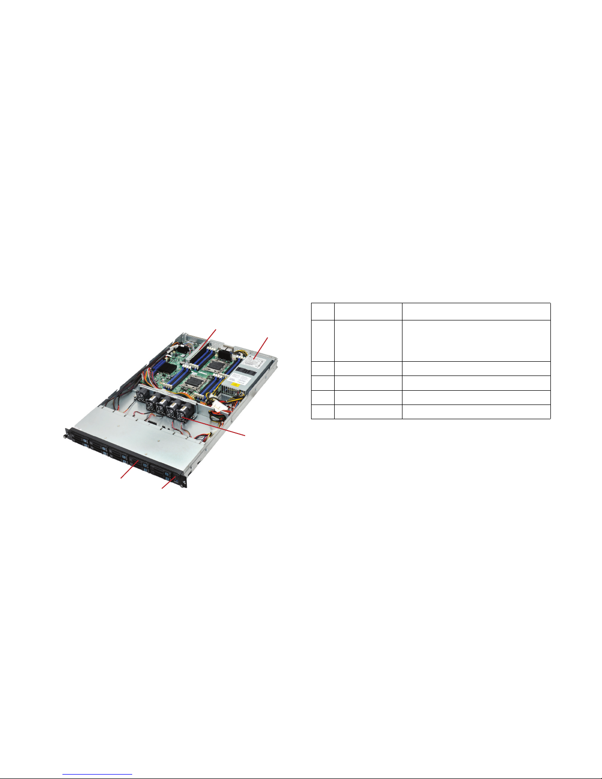
2.5” HDD System
Figure 1-1. 2.5” System Component Overview
1
2
3
4
5
Table 1-2: 2.5” System Component Overview
NO. ITEM DESCRIPTION
1 Riser Assembly
(1) PCIe x16 G3 slot for standard height,
half-length card.
(1) PCIe x8 G3 Quanta LSISAS/RAID
Mezzanine slot
2 PSU (1) Power supply units
3 System Fan (5) Fan module assembly
4 Front Panel Control and LED panel for system status
5 2.5 Hard Drives (10) 2.5” hard disk drives (HDD)
Page 26
ABOUT THE SERVER 3.5” HDD SYSTEM
1-5
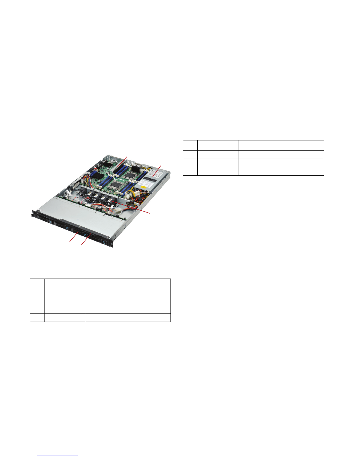
3.5” HDD System
Figure 1-2. 3.5” System Component Overview
Table 1-3: 3.5” System Component Overview
NO. ITEM DESCRIPTION
1 Riser Assembly
(1) PCIe x16 G3 slot for standard height,
half-length card
(1) PCIe x8 G3 Quanta LSISAS/RAID
Mezzanine slot
2 PSU (1) Power supply units
1
2
3
4
5
3 System Fan (5) Fan module assembly
4 Front Panel Control and LED panel for system status
5 3.5 Hard Drives (4) 3.5” hard disk drives (HDD).
Table 1-3: 3.5” System Component Overview
NO. ITEM DESCRIPTION
Page 27
ABOUT THE SERVER SYSTEM FRONT FEATURES
1-6
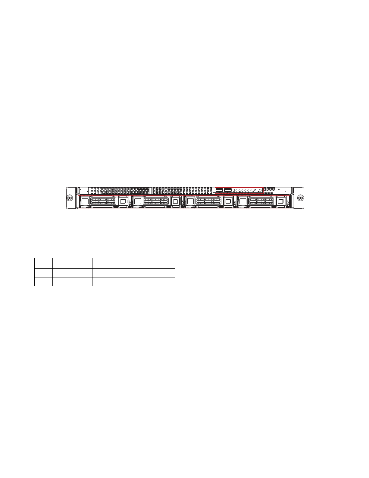
System Front Features
3.5” HDD SKU
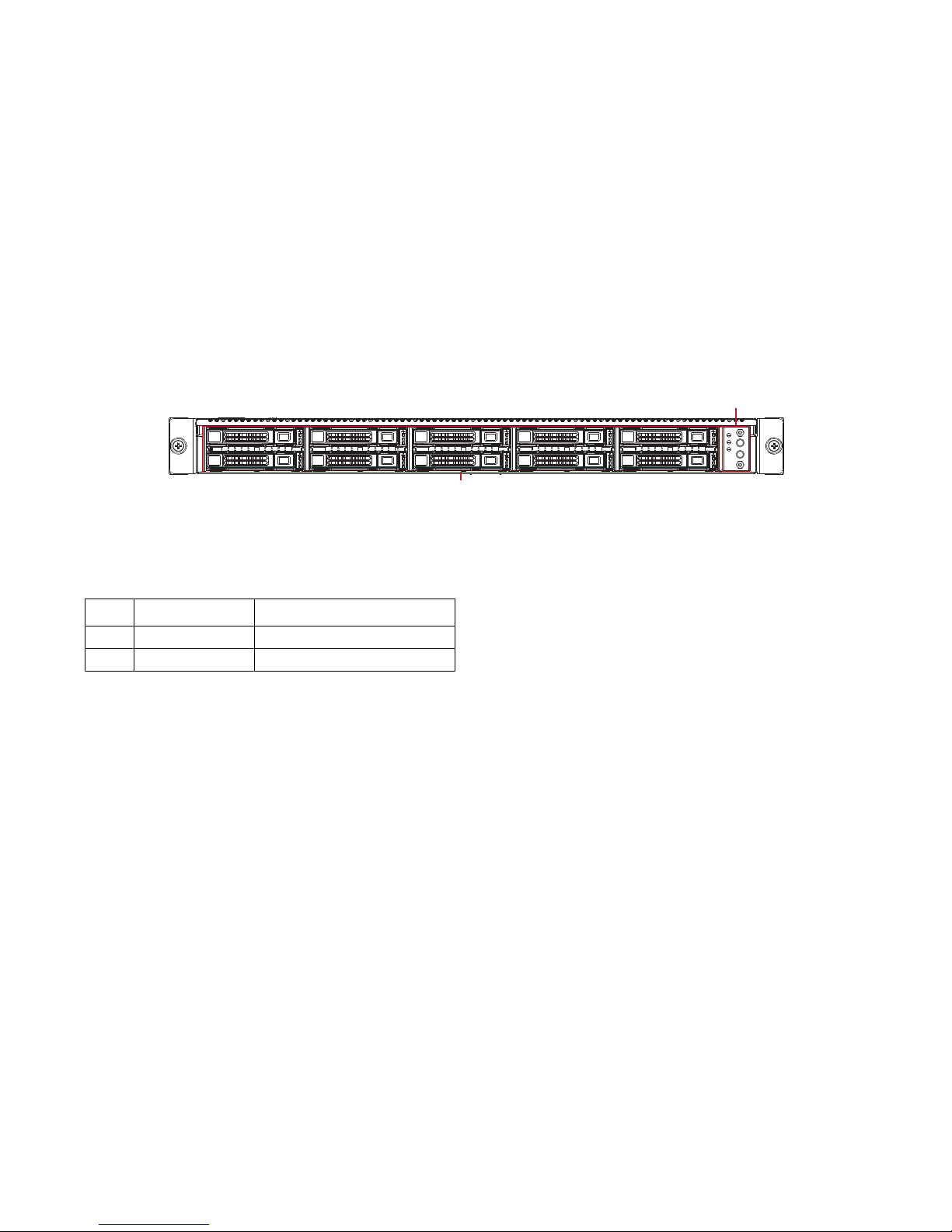
Figure 1-3. 3.5” HDD SKU Front Features
3.5” Front Panel Definition
1
2
Table 1-4: 3.5” HDD Front Panel Definition
I
TEM NAME DESCRIPTION
1 Control Panel Connect USB devices to these ports
2 HDD Bays Insert HDDs here.
Page 28
ABOUT THE SERVER SYSTEM FRONT FEATURES
1-7
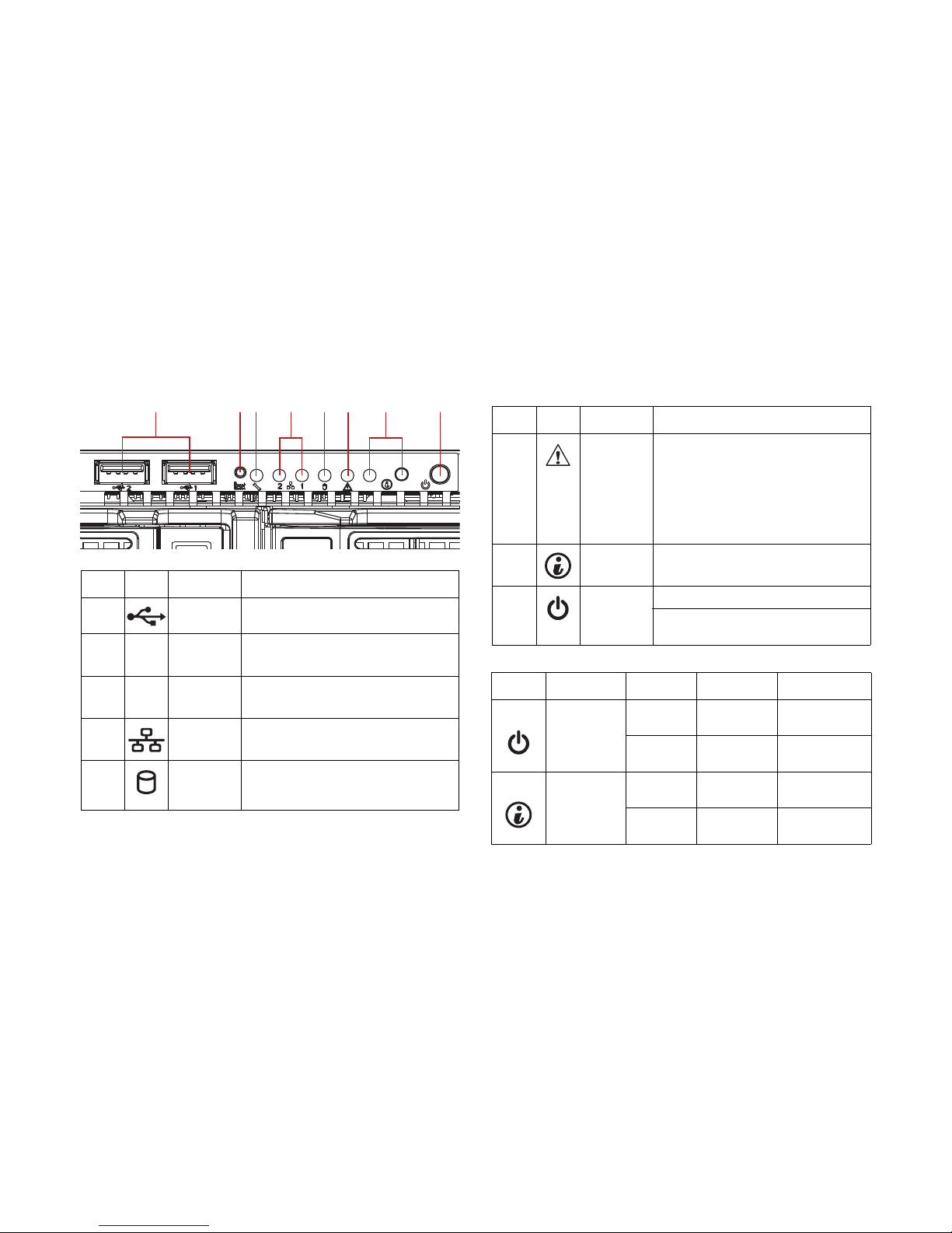
3.5” Control Panel
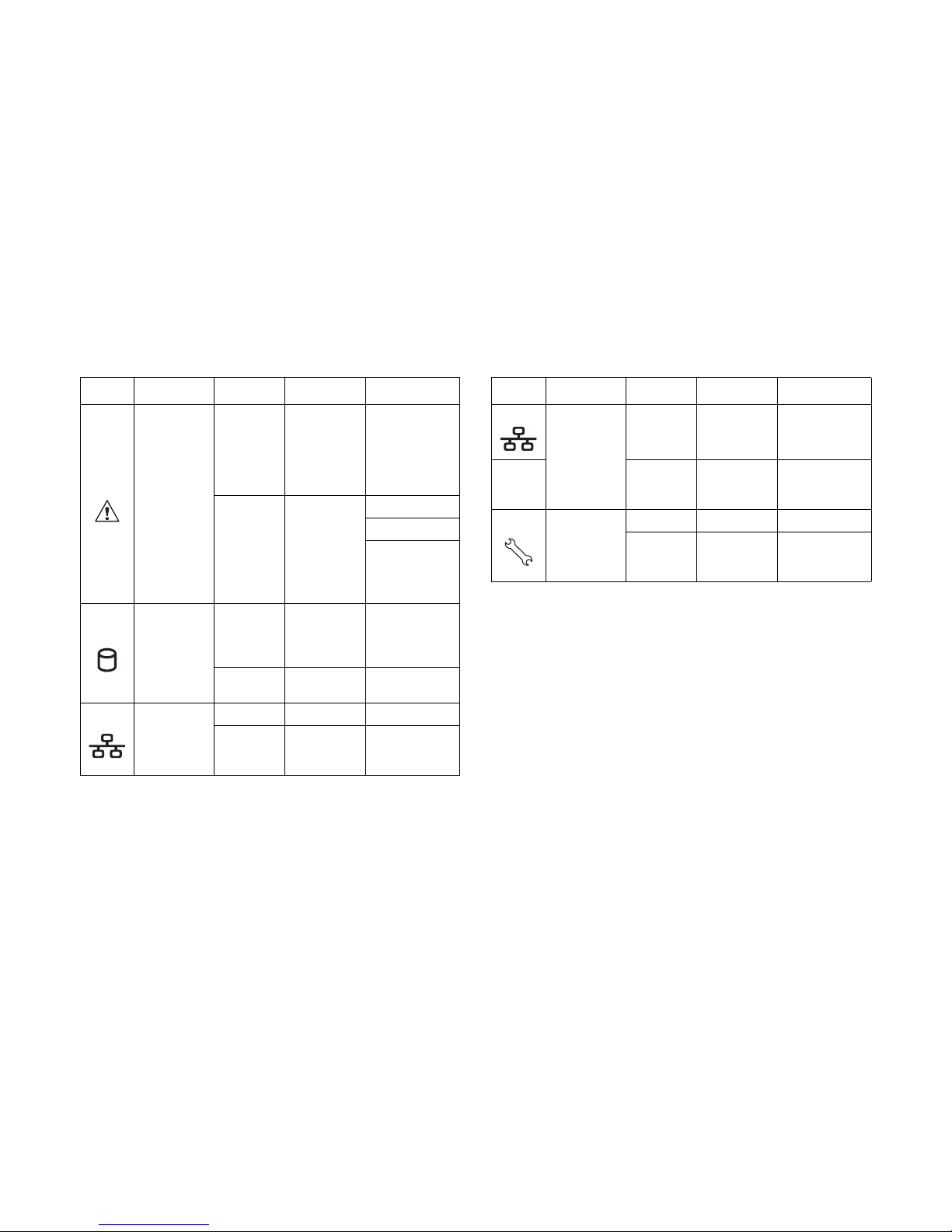
Table 1-5: 3.5” HDD LED Function and Behavior
I
TEM ICON NAME DESCRIPTION
1
Front USB
ports
Connect USB devices to these ports
2
Reset
Button
Push button to Reset system
3MGMT LED
Green ON, link
Green Blinking, LAN access
4
LAN 2/1
LED
Green ON, link Green Blinking, LAN
access
5
HDD
Activity
LED
Green Blinking, HDD access OFF, no
access
123 456 7 8
6 Event LED
Amber Blinking:
Critical failure: fan, voltage, temperature
state
Non-critial failure: fan, voltage,
temperature state, CPU, thermal trip
OFF: SEL cleared, DC off, last pending
warning/error de-asserted
7
ID Button
with LED
Blue Blinking, selected unit ID
OFF, no ID requested
8
Power
button with
LED
Green ON
Based on System Off, Push Button to
PSU and System off
Table 1-6: 3.5” HDD Front LED Function & Behavior
M
ARK NAME COLOR CONDITION DESCRIPTION
Power LED
Green On
System power
on
N/A Off
System power
off
Identification
Blue Blinking
Unit selected
for identification
N/A Off
No identification
required
Table 1-5: 3.5” HDD LED Function and Behavior (Continued)
I
TEM ICON NAME DESCRIPTION
Page 29
ABOUT THE SERVER SYSTEM FRONT FEATURES
1-8
Fault LED
Amber Blinking
Critical failure:
critical fan,
voltage,
temperature
state, CPU
thermal trip
N/A Off
SEL cleared
DC off
Last pending
warning or error
has been deasserted
HDD Activity
Green Blinking
Hard disk drive
access (only on
board SATA
port)
N/A Off
No access
(non-SAS)
LAN 1 LED
Green On Link
Green Blinking
LAN access (off
when there is
traffic)
Table 1-6: 3.5” HDD Front LED Function & Behavior (Continued)
M
ARK NAME COLOR CONDITION DESCRIPTION
LAN 2 LED
Green On Link
Green Blinking
LAN access (off
when there is
traffic)
Service LED
Green On Link
Green Blinking
LAN access (off
when there is
traffic)
Table 1-6: 3.5” HDD Front LED Function & Behavior (Continued)
M
ARK NAME COLOR CONDITION DESCRIPTION
Page 30
ABOUT THE SERVER SYSTEM FRONT FEATURES
1-9
2.5” HDD SKU
Figure 1-4. 2.5” HDD SKU System Front Features
2.5” Front Panel Definition
2
1
Table 1-7: 2.5” HDD Front Panel Definition
I
TEM NAME DESCRIPTION
1 Control Panel Connect USB devices to these ports
2 HDD Bays Insert HDDs here.
Page 31

ABOUT THE SERVER SYSTEM FRONT FEATURES
1-10
2.5” Control Panel
Table 1-8: 2.5” HDD LED Function and Behavior
I
TEM ICON NAME DESCRIPTION
1 Event LED
Amber Blinking:
Critical failure: fan, voltage,
temperature state
Non-critial failure: fan, voltage,
temperature state, CPU, thermal trip
OFF: SEL cleared, DC off, last
pending warning/error de-asserted
2 LAN1/2 LED
Green ON, link
Green Blinking, LAN access
3
Power
Button with
LED
Green ON
Based on System Off, Push Button to
PSU and System off
4
ID button
with LED
Blue Blinking, selected unit ID
OFF, no ID requested
1
2
3
4
Table 1-9: 2.5” 2.5” Front Panel Definition
N
O ICON NAME DESCRIPTION
1 Fault LED
Displays status/errors and is
controlled by BMC.
2
Power
Button/LED
Lights Green when server is powered
on.
3
System ID
LED
Blinking when the system has been
selected for identification.
4
LAN1/LAN2
LED
LAN1/LAN2 LED
5
HDD
Location
HDD 0/HDD 1/HDD 2/HDD 3/HDD 4/
HDD 5/HDD 6/HDD 7/ HDD 8/ HDD 9
Table 1-10: 2.5” Front Side LED Function and Behavior
I
CON NAME COLOR CONDITION DESCRIPTION
Power LED
Green On
System power
on
-- Off
System power
off
Identificaiton
Blue Blinking
Unit selected
for identification
-- Off
No identification
requested
Page 32

ABOUT THE SERVER SYSTEM FRONT FEATURES
1-11
Fault LED
Amber Blinking
Critical failure:
critical fan,
voltage,
temperature
state
Non-critical
failure: noncritical fan,
voltage,
temperature
state, CPU
thermal trip
-- Off
SEL cleared
DC off
Last pending
warning or error
has been deasserted
LAN 1 LED
Green Blinking LAN access
-- Off LAN no access
LAN 2 LED
Green Blinking LAN access
-- Off LAN no access
Table 1-10: 2.5” Front Side LED Function and Behavior (Continued)
I
CON NAME COLOR CONDITION DESCRIPTION
Page 33

ABOUT THE SERVER SYSTEM HDD SKU INTRODUCTION
1-12
System HDD SKU Introduction
The system is available in a 2.5” and a 3.5” HDD form factor.
2.5” HDD Configuration
Figure 1-5. 2.5” HDD Configuration
3.5” HDD Configuration
Figure 1-6. 3.5” HDD Configuration
HDD 1
HDD 0 HDD 2
HDD 3
HDD 4
HDD 5
HDD 6
HDD 7
HDD 8
HDD 9
HDD 0 HDD 1 HDD 2 HDD 3
Page 34

ABOUT THE SERVER SYSTEM REAR FEATURES
1-13
System Rear Features
S210-X12MS System Rear View
Figure 1-7. System Rear Features
12
3
4
5678910
Table 1-11: System Rear Features
I
TEM FEATURE DESCRIPTION
1 Power Supply Unit 1 Power supply unit
2 LAN Ports (LAN1 / LAN2) 1 GbE LAN ports (x2)
3 Fault LED
Displays status/errors and is
controlled by BMC
4 PCI-E Slot PCI-E Gen3 x 16 Riser Slot
5 10 GbE SFP+ 10 GbE SFP+ port (x2)
6 System ID LED
Blinking when the system has
been selected for identification
7 Management Port (LAN3)
10/100 BASE-T RJ45
management port
8 USB Port USB port (x4)
9 VGA Port Connects a monitor
10 Seriail Port Connects serial devices
Note:
The 2.5” HDD SKU and 3.5” HDD SKU only support a
single PSU.
Table 1-11: System Rear Features (Continued)
I
TEM FEATURE DESCRIPTION
Page 35

ABOUT THE SERVER SYSTEM REAR FEATURES
1-14
S210-X12MS System I/O LED Description
2.5” and 3.5” HDD SKU Rear I/O LED Description
Table 1-12: Rear LED Function and Behavior
I
CON NAME COLOR CONDITION DESCRIPTION
LAN1/LAN2 LED
(Left and right)
Link/Act
Green On LAN link
Green Blinking LAN access (off when there is traffic)
-- OFF Disconnected
Speed
Amber ON Link speed is 100Mbits/sec
Green ON Link speed is 1000Mbits/sec
-- OFF OFF, link speed is 10M bits/sec
Service Port
(LAN 3) LED
Link/Act
Green On LAN link
Green Blinking LAN access (off when there is traffic)
-- OFF Disconnected
Speed
Green ON Link speed is 100Mbits/sec
-- OFF Link speed is 10M bits/sec
Fault LED
Amber ON
Critical Failure: critical fan, voltage,
temperature state.
-- OFF No critical failure.
Identification LED
Blue Blinking Unit selected for identification
-- OFF No identification requested
Page 36

ABOUT THE SERVER SYSTEM REAR FEATURES
1-15
10 GbE SFP+
LAN LED (x2)
Link/Act
Amber
(1G)
Green
(10G)
ON LAN link
Green ON LAN access
-- OFF Disconnected
Speed
Green ON Link speed is 10G bits/sec (Port0)
Amber ON Link speed is 1G bits/sec (Port0)
Table 1-12: Rear LED Function and Behavior (Continued)
I
CON NAME COLOR CONDITION DESCRIPTION
Page 37

Installing Hardware
Chapter 2
Installing Hardware
Chapter 2
Page 38

INSTALLING HARDWARE SAFETY MEASURES
2-1
2.1 Safety Measures
WARNING!
Always ask for assistance to move or lift the system.
WARNING!
Only perform troubleshooting as authorized by the product
documentation, or as directed by a service and support team.
Repairs not authorized by warranty may void the warranty
and damage the system.
WARNING!
Always make sure to disconnect the system from the
electrical source. Powering down the system DOES NOT
insure the system is safe for repairs.
WARNING!
Server components and circuit boards are easily damaged by
discharges of static electricity. Working on servers that are
connected to a power supply can be extremely dangerous.
WARNING!
Always disconnect the server from the power outlet whenever
you are working inside the server case.
!
!
!
!
!
WARNING!
Wear a grounded wrist strap. If none are available, discharge
any personal static electricity by touching the bare metal
chassis of the server case, or the bare metal body of any
other grounded device.
WARNING!
Humid environments tend to have less static electricity than
dry environments. A grounding strap is warranted whenever
danger of static electricity exists.
WARNING!
Do not touch the components on the boards unless it is
necessary to do so. Do not flex or stress circuit boards.
WARNING!
Leave all replacement components inside their static-proof
packaging until you are ready to use them.
!
!
!
!
Page 39

INSTALLING HARDWARE TOP COVER
2-2
2.2 Top Cover
Opening the Top Cover
1. Turn off the system and any attached peripherals.
2. Unplug the AC power cables and disconnect all peripherals, LAN lines and any other cables.
3. Press the top cover release button and slide the rear
top cover away from the HDDs.
4. Lift the top cover off the chassis .
Figure 2-1. Opening the Top Cover
Page 40

INSTALLING HARDWARE CLOSING THE TOP COVER
2-3
Closing the Top Cover
1. Place the top cover on the chassis.
2. Slide the top cover toward the HDDs.
Figure 2-2. Closing the Top Cover
Page 41

INSTALLING HARDWARE HARD DISK DRIVES
2-4
2.3 Hard Disk Drives
The following procedures demonstrate installation and removal of 2.5 and 3.5 inch hard drives.
Removing a 2.5” Hard Drive
Hard drives are numbered. For more details, refer to System
HDD SKU Introduction on page 1-12.
1. Press the tray handle button.
Figure 2-3. Opening the Hard Drive Tray Handle
2. Pull the HDD tray handle open .
Figure 2-4. Removing a 2.5” Hard Drive Tray
3. Remove the tray out of the system .
WARNING!
Repairs should be perfomed by a certified service technician. Damage to the system or components due to unauthorized servicing
is not covered by the warranty agreement.
!
1
2
Page 42

INSTALLING HARDWARE INSTALLING A 2.5” HARD DRIVE
2-5
4. Remove the four (4) screws securing the hard drive to the
HDD tray.
Figure 2-5. Removing a 2.5” HDD from the Tray
Installing a 2.5” Hard Drive
1. Align the 2.5” hard drive tray with the new hard drive and
secure with the four (4) screws
Figure 2-6. Installing a 2.5” HDD on the Tray
2. Align the tray assembly with the HDD bay and insert the
assembly until it is fully seated in the bay.
Figure 2-7. Installing a 2.5” HDD in the System
2
1
Page 43

INSTALLING HARDWARE REMOVING A 3.5” HARD DISK DRIVE
2-6
3. Close the HDD tray handle .
Removing a 3.5” Hard Disk Drive
Hard drives are numbered. For more details, refer to System
HDD SKU Introduction on page 1-12.
1. Press the tray handle button.
Figure 2-8. Opening the Hard Drive Tray Handle
2. Pull the hard drive tray handle completely open.
WARNING!
Do not force the tray handle closed. If resistance is
encountered check the hard drive is properly inserted and the
hard drives on either side are properly inserted.
!
Page 44

INSTALLING HARDWARE REMOVING A 3.5” HARD DISK DRIVE
2-7
Figure 2-9. Removing the 3.5” Hard Drive Tray
3. Remove the tray from the system.
4. Remove the four (4) screws securing the hard drive to the
HDD tray.
Figure 2-10. Removing a 3.5” HDD from the Tray
WARNING!
Make sure the hard drive tray handle is in the fully open
position.
2
3
!
Page 45

INSTALLING HARDWARE INSTALLING A 3.5” HARD DISK DRIVE
2-8
Installing a 3.5” Hard Disk Drive
1. Align the 3.5” hard drive tray with the new hard drive and
secure with the four (4) screws
Figure 2-11. Installing a 3.5” HDD on the Tray
2. Align the tray assembly with the HDD bay and insert the
HDD until it is fully seated in the bay.
Figure 2-12. Installing a 3.5” Hard Drive
3. Push the tray handle closed.
WARNING!
Do not force the tray handle closed. If resistance is
encountered, check the hard drive is properly inserted and the
hard drives on either side are properly inserted.
2
3
!
Page 46

INSTALLING HARDWARE AIR DUCT
2-9
2.4 Air Duct
Removing the Air Duct
Prerequisite:
Prerequisite:
Power down the system.
Disconnect all cables and peripherals from the system.
Remove the system cover.
Refer to the following illustrations for instructions on removing
the air duct:
1. Locate the air duct on the chassis.
2. Remove the air duct from the chassis.
Figure 2-13. Removing the Air Duct
Installing the Air Duct
Prerequisite:
Prerequisite:
Power down the system.
Disconnect all cables and peripherals from the system.
Remove the system cover.
Refer to the following illustrations for instructions on removing
the air duct:
1. Align the front of the air duct over the middle bracket.
Make sure the air duct inset is inserted into the middle
bracket.
Make sure the sides of the air duct are tucked under the
middle bracket.
Page 47

INSTALLING HARDWARE INSTALLING THE AIR DUCT
2-10
Figure 2-14. Installing the Air Duct
2. Align the fan duct over the CPU0 socket and CPU0 memory modules.
Figure 2-15. Installing the Air Duct
Page 48

INSTALLING HARDWARE FAN MODULE ASSEMBLY
2-11
2.5 Fan Module Assembly
Removing the Fan Module Assembly
Prerequisite:
Prerequisite:
Remove the top cover. See Opening the Top Cover on
page 2-2
1. Disconnect five (5) fan module cables from the connectors on the HDD backplane.
2. Remove two (2) screws securing the fan module assembly to the chassis.
Figure 2-16. Removing the Fan Module Assembly Screws
3. Remove the fan module assembly from the chassis.
Page 49

INSTALLING HARDWARE INSTALLING THE FAN MODULE ASSEMBLY
2-12
Installing the Fan Module Assembly
Prerequisite:
Prerequisite:
Remove the top cover. See Opening the Top Cover on
page 2-2.
1. Align the fan module assembly with the screw holes on
the chassis.
Figure 2-17. Installing Fan Module Assembly Screws
2. Secure the fan module assembly to the chassis with two
(2) screws.
3. Connect five (5) fan module cables to the connectors on
the HDD backplane.
Page 50

INSTALLING HARDWARE MEMORY MODULES
2-13
2.6 Memory Modules
General Guidelines
All servers have specific rules for the population of memory on
the individual mainboards that must be obeyed. Refer to the following individual server rules for information on how to populate
the particular server required.
Removing Memory Modules
Prerequisite:
Prerequisite:
Remove the top cover. See Opening the Top Cover on
page 2-2.
1. Press down on the two memory module slot levers .
The memory module partially ejects.
Figure 2-18. Removing Memory Modules
2. Lift out the memory module
WARNING!
S210-X12MS mainboards are supplied with all DIMM slots
populated with memory 9 dummies for proper air flow. When
installing and replacing memory modules, only remove those
dummies that are to be directly replaced. All S210-X12MS
DIMM slots must be occupied at all times by either a memory
module or dummy cover.
WARNING!
Memory modules remain hot after the system is powered
down. Allow sufficient time for the memory modules to cool
before handling system components.
!
!
WARNING!
Handle the memory module by the edges at all times.
1
2
!
Page 51

INSTALLING HARDWARE INSTALLING MEMORY MODULES
2-14
Installing Memory Modules
Prerequisite:
Prerequisite:
Remove the top cover. See Opening the Top Cover on
page 2-2.
1. Align the notch on the memory module with the obstruction on the slot.
Figure 2-19. Installing Memory Modules
2. Push the memory module firmly into the memory module
slot. The locking latches automatically lock in place.
WARNING!
Handle the memory module by the edges at all times.
!
Page 52

INSTALLING HARDWARE MEMORY POPULATION RULES
2-15
Memory Population Rules
Figure 2-20. Memory Population Rules
CPU 0
CPU 1
CPU 1 C-F DIMM F2
CPU 1 C-F DIMM F1
CPU 1 C-E DIMM E2
CPU 1 C-E DIMM E1
CPU 1 C-H DIMM H2
CPU 1 C-H DIMM H1
CPU 1 C-G DIMM G2
CPU 1 C-G DIMM G1
CPU 0 C-C DIMM C1
CPU 0 C-C DIMM C2
CPU 0 C-D DIMM D1
CPU 0 C-D DIMM D2
CPU 0 C-A DIMM A1
CPU 0 C-A DIMM A2
CPU 0 C-A DIMM B1
CPU 0 C-A DIMM B2
Page 53

INSTALLING HARDWARE MEMORY POPULATION RULES
2-16
Table 2-1: UDIMM Support
R
ANKS PER
DIMM &
DATA WIDTH
MEMORY
CAPACITY
PER DIMM (GB)
1*
SPEED
(MT/S) & VOLTAGE VALIDATED
BY SLOT PER CHANNEL (SPC) & DIMM
PER CHANNEL (DPC)
2,3*
2 Slots per Channel
1DPC (V) 2DOC (V)
1.35 1.5 1.35 1.5
SR x 8
Non-ECC
1
a*
2b*4
b*
n/a
1066,
1333
n/a
1066,
1333
DR x 8
Non-ECC
2
a*
4b*8
b*
n/a
1066,
1333
n/a
1066,
1333
SR x 16
Non-ECC
512
a*1a*2a*
n/a
1066,
1333
n/a
1066,
1333
SR x 8
ECC
1
a*
2b*4
b*
1066
1066,
1333
1066
1066,
1333
DR x 8
ECC
2
a*
4b*8
b*
1066
1066,
1333
1066
1066,
1333
Important:
a*: Supported but not validated.
b*: Supported and validated.
Note:
1*: Supported DRAM densities are 1GB, 2GB, and 4 GB. Only 2
GB and 4 GB are validated by Intel.
2*: Command Address Timing is 1N for 1DPC and 2N for 2DPC.
3*: Romley-EP/EX platform does not support 3DPC when using
UDIMMs.
Table 2-2: RDIMM Support
R
ANKS
PER DIMM
&
DATA
WIDTH
MEMORY
CAPACITY
PER DIMM (GB)
1*
SPEED
(MT/S) & VOLTAGE VALIDATED
BY SLOT PER CHANNEL (SPC) & DIMM
PER CHANNEL (DPC)
2,3*
2 Slots per Channel
1DPC (V) 2DOC (V)
1.35 1.5 1.35 1.5
SR x 8
1
a*2b*
4
b*
1066,
1333
1066,
1333,
1600
1066,
1333
1066,
1333,
1600
DR x 8
2
a*4b*
8
b*
1066,
1333
1066,
1333,
1600
1066,
1333
1066,
1333,
1600
SR x 4
2
a*4a*
8
a*
1066,
1333
1066,
1333,
1600
1066,
1333
1066,
1333,
1600
DR x 4
4
a*8b*
16
b*
1066,
1333
1066,
1333,
1600
1066,
1333
1066,
1333,
1600
QR x 4
8
a*
16c*32
c*
800 1066 800 800
Page 54

INSTALLING HARDWARE MEMORY POPULATION RULES
2-17
QR x 8
4
a*8c*
16
c*
800 1066 800 800
Table 2-2: RDIMM Support
R
ANKS
PER DIMM
&
DATA
WIDTH
MEMORY
CAPACITY
PER DIMM (GB)
1*
SPEED
(MT/S) & VOLTAGE VALIDATED
BY SLOT PER CHANNEL (SPC) & DIMM
PER CHANNEL (DPC)
2,3*
Important:
a*: Supported but not validated.
b*: Supported and validated.
c*: Supported with limited validation
Note:
1*: Supported DRAM densities are 1GB, 2GB, and 4 GB. Only 2
GB and 4 GB are validated by Intel.
2*: Command Address Timing is 1N.
3*: QR RDIMM are supported but only validated by Intel/PMO in a
homogenous environment. The coverage will have limited system
level testing, no signal integrity testing, and no interoperability
testing The passing QR RDIMMs will be web posted.
Table 2-3: LRDIMM Support
R
ANKS PER
DIMM & DATA
WIDTH1*
MEMORY
CAPACITY PER
DIMM (GB)
2*
SPEED
(MT/S) & VOLTAGE VALIDATED BY
SLOT PER CHANNEL (SPC) & DIMM PER
CHANNEL (DPC)
3,4,5,6*
3 Slots per Channel
1DPC (V) & 2DOC
(V)
3DOC (V)
1.35 1.5 1.35 1.5
QR x 4
(DDP)
7
*
16 32 1066
1066,
1333
1066 1066
DR x 8
7*
8161066
1066,
1333
1066 1066
Page 55

INSTALLING HARDWARE POWER SUPPLY UNIT
2-18
2.7 Power Supply Unit
The S210-X12MS server models support a single power supply as shown in the following illustrations.
Removing a Power Supply Unit
1. Disconnect the power cables from the mainboard connectors.
2. Remove six (6) screws securing the PSU to the chassis.
Figure 2-21. Removing the PSU Screws
3. Remove the PSU from the chassis.
CAUTION!
DISCONNECT THE POWER SUPPLY UNIT FROM THE POWER
SOURCE BEFORE REMOVING PSU. FAILURE TO DO SO
COULD RESULT IN DAMAGE TO THE EQUIPMENT OR PER-
SONAL INJURY.
!
Page 56

INSTALLING HARDWARE INSTALLING A POWER SUPPLY UNIT
2-19
Installing a Power Supply Unit
1. Place the PSU in the chassis.
2. Slide the PSU until seated in the rear of the chassis.
Figure 2-22. Securing the PSU Screws
3. Secure the PSU to the chassis with six (6) screws.
4. Connect the power cables to the mainboard connectors.
Page 57

INSTALLING HARDWARE PROCESSOR HEAT SINKS
2-20
2.8 Processor Heat Sinks
Removing a Heat Sink
Prerequisite:
Prerequisite:
Remove the top cover. See Opening the Top Cover on
page 2-2.
1. Loosen the four (4) captive screws securing the heat sink
to the mainboard.
Figure 2-23. Removing the Heat Sink
2. Remove the heat sink.
Installing a Heat Sink
Prerequisite:
Prerequisite:
Remove the top cover. See Opening the Top Cover on
page 2-2
1. Align the heat sink. Make sure the airflow sticker points to
the rear of the chassis.
2. Place the heat sink on the processor.
CAUTION!
THE HEATSINK REMAINS HOT AFTER THE SYSTEM HAS
BEEN POWERED DOWN. ALLOW SUFFICIENT TIME TO COOL
BEFORE HANDLING SYSTEM COMPONENTS.
!
1
3
2
4
Important:
Tighten the captive screws in the sequence indicated in the
illustration.
Page 58

INSTALLING HARDWARE INSTALLING A HEAT SINK
2-21
3. Secure the heat sink with four (4) screws. The screws
must be secured in the sequence indicated in the illustration.
Figure 2-24. Installing the Heat Sink
1
3
2
4
Page 59

INSTALLING HARDWARE PROCESSORS
2-22
2.9 Processors
Removing a Processor
Prerequisite:
Prerequisite:
Remove the top cover. See Opening the Top Cover on
page 2-2.
Remove the CPU heatsink. See Removing a Heat Sink
on page 2-20.
1. Carefully press down and outwards on the right processor
locking lever to release it.
Figure 2-25. Releasing the Right Processor Locking
Lever
2. Carefully press down and outwards on the left processor
locking lever, pulling it fully open.
Figure 2-26. Releasing the Left Processor Locking Lever
Open 1st
Closed 1st
WARNING!
Do not try to pull the right-hand processor locking lever
fully open.
CAUTION!
THE LOCKING LEVER IS HELD UNDER CONSIDERABLE
FORCE AND MAY SPRING UP UNEXPECTEDLY.
!
Open 1st
Closed 1st
!
Page 60

INSTALLING HARDWARE REMOVING A PROCESSOR
2-23
3. Press down on the right processor locking lever to lift the
processor cover part way and then lift the processor load
plate to the fully open position.
Figure 2-27. Opening the Processor Cover
4. Lift the processor out of the socket.
Figure 2-28. Removing the Processor
CAUTION!
AVOID CONTACT WITH THERMAL GREASE ON THE PROCES-
SOR.
!
Page 61

INSTALLING HARDWARE INSTALLING A PROCESSOR
2-24
Installing a Processor
Prerequisite:
Prerequisite:
Remove the top cover. See Opening the Top Cover on
page 2-2.
Remove the CPU heat sink. See Removing a Heat Sink
on page 2-20.
1. Align the gold triangle identifying pin 1 of the processor
with the triangular cutout of the processor, and the four (4)
indents on processor with the four (4) tabs on socket.
Figure 2-29. Installing the Processor
2. Insert the processor into the socket, ensuring the four
keys on the socket fit into the corresponding keys on the
processor.
3. Lower the processor load plate over the processor .
Figure 2-30. Closing the Processor Cover
4. Push the left processor locking lever down and latch it
into the locked position . The protective plastic cover
pops out as the latch is engaged.
5. Push the right processor locking lever down and latch it
into the locked position .
Indent
Pin 1
Ta b
WARNING!
The processor should fit easily into the socket. Do not
force the processor in place.
Note:
Use the socket cover to protect the socket when the socket is
empty.
!
Open 1st
Closed 1st
Page 62

INSTALLING HARDWARE MAINBOARD MODULE
2-25
2.10 Mainboard Module
Removing a Mainboard Module
Prerequisite:
Prerequisite:
Remove the top cover. See Opening the Top Cover on
page 2-2
1. Remove nine (9) screws securing mainboard to chassis.
Figure 2-31. Removing the Mainboard Module Screws
2. Pull mainboard towards the front of the chassis until free
of the chassis port openings.
3. Remove the mainboard from the chassis.
D2/D1/C2/C1A1/A2/B1/B2
F2/F1/E2/E1G1/G2/H1/H2
CPU 0
CPU 1
Page 63

INSTALLING HARDWARE INSTALLING MAINBOARD MODULE
2-26
Installing Mainboard Module
Prerequisite:
Prerequisite:
Remove the top cover. See Opening the Top Cover on
page 2-2
1. Place the mainboard on the chassis.
2. Align the mainboard with the port openings on the rear of
the chassis.
3. Install the mainboard on the chassis.
4. Secure the mainboard to the chassis with the nine (9)
screws.
Figure 2-32. Installing the Mainboard Module Screws
D2/D1/C2/C1A1/A2/B1/B2
F2/F1/E2/E1G1/G2/H1/H2
CPU 0
CPU 1
Page 64

INSTALLING HARDWARE PCI-E RISER ASSEMBLY
2-27
2.11 PCI-E Riser Assembly
Removing PCI-E Riser Assembly
Prerequisite:
Prerequisite:
Open the top cover. See Opening the Top Cover on
page 2-2.
1. Remove one (1) screw securing the assembly to the
chassis.
Figure 2-33. Removing the PCI-E Riser Assembly (1 of 2)
2. Remove the assembly from the chassis.
Figure 2-34. Removing the PCI-E Riser Assembly (2 of 2)
Page 65

INSTALLING HARDWARE INSTALLING PCI-E RISER ASSEMBLY
2-28
Installing PCI-E Riser Assembly
Prerequisite:
Prerequisite:
Open the top cover. See Opening the Top Cover on
page 2-2.
1. Align the assembly with the guide pin hole in the chassis.
Figure 2-35. Installing the PCI-E Riser Assembly (1 of 2)
2. Insert the linking board into the connector on the mainboard.
3. Secure the assembly to the chassis with one (1) screw.
Figure 2-36. Installing the PCI-E Riser Assembly (2 of 2)
1.
Page 66

INSTALLING HARDWARE PCI-E CARD
2-29
2.12 PCI-E Card
Removing the PCI-E Card
Prerequisite:
Prerequisite:
Remove the top cover. See Opening the Top Cover on
page 2-2.
Remove the PCI-E riser assembly. See Removing PCI-E
Riser Assembly on page 2-27
1. Remove one (1) screw to release the PCI-E card.
Figure 2-37. Removing the PCI-E Card
2. Remove the PCI-E card from the riser assembly.
Figure 2-38. Removing the PCI-E Card
Page 67

INSTALLING HARDWARE INSTALLING THE PCI-E CARD
2-30
Installing the PCI-E Card
Prerequisite:
Prerequisite:
Remove the top cover. See Opening the Top Cover on
page 2-2.
Remove the PCI-E riser assembly. See Removing PCI-E
Riser Assembly on page 2-27.
1. Align the PCI-E card with the riser assembly and slide in
place.
Figure 2-39. Installing the PCI-E Card
2. Secure with the single screw.
3. Install the PCI-E and riser assembly in the chassis.
4. Secure the riser assembly
Figure 2-40. Installing the PCI-E Card
.
Page 68

INSTALLING HARDWARE EXPANDER BACKPLANE
2-31
2.13 Expander Backplane
Removing the Expander Backplane
Prerequisite:
Prerequisite:
Remove the top cover. See Opening the Top Cover on
page 2-2.
1. Disconnect the following cables from the expander backplane (BP):
a. Golden finger for LED signals to HDD BP B2B connec-
tor.
b. Golden finger for LED signals to HDD BP B2B connec-
tor.
c. Golden finger for LED signals to HDD BP B2B connec-
tor.
d. 10 pin Power connector for BP with +12V, +5V,
+3.3V,GND
e. LSI SAS2x20 SAS 6G Expander IC.
f. SAS_1, Mini-SAS connector to Host Port 1 channel 4
~ 7.
g. SAS_0, Mini-SAS connector to Host Port 0 channel 0
~ 3.
h. System FAN 5 for CPU 1 Block
i. System FAN 4 for CPU 1 Block
j. System FAN 3 for CPU 1 Block
k. System FAN 2 for CPU 0 Block
l. System FAN 1 for CPU 0 Block
m. System FAN 0 for CPU 0 Block
n. Jumper setting of Expander operation mode
o. IPMB connector linking to on board BMC controller
FAN Speed
p. Winbond W83793 for FAN control
Page 69

INSTALLING HARDWARE REMOVING THE EXPANDER BACKPLANE
2-32
Figure 2-41. Expander Board Connectors
2. Remove four (4) screws from the HDD expander board.
Figure 2-42. Removing the Expander Board Screws
3. Slide the expander BP toward the rear of the chassis until
the guide pins are clear of the guide pins.
4. Remove the expander board.
Figure 2-43. Removing the Expander Board
ab c
d
e f
gh i j k l mn op
Guide Pin
Guide Pin
Page 70

INSTALLING HARDWARE INSTALLING THE EXPANDER BACKPLANE
2-33
Installing the Expander Backplane
Prerequisite:
Prerequisite:
Remove the top cover. See Opening the Top Cover on
page 2-2.
Install the HDD backplane. See Installing the HDD Back-
plane (2.5” SKU) on page 2-36.
1. Align the holes in the expander board with the guide pins
on the chassis.
2. Slide the expander board into the connectors on the
backplane.
Figure 2-44. Installing the Expander Board
3. Secure the expander board to the chassis with four (4)
screws.
Figure 2-45. Installing the Expander Backplane Screws
HDD Backplane
Guide Pins
Guide Pins
Page 71

INSTALLING HARDWARE INSTALLING THE EXPANDER BACKPLANE
2-34
4. Connect the following cables to the expander BP:
a. Golden finger for LED signals to HDD BP B2B connec-
tor.
b. Golden finger for LED signals to HDD BP B2B connec-
tor.
c. Golden finger for LED signals to HDD BP B2B connec-
tor.
d. 10 pin Power connector for BP with +12V, +5V,
+3.3V,GND
e. LSI SAS2x20 SAS 6G Expander IC.
f. SAS_1, Mini-SAS connector to Host Port 1 channel 4
~ 7.
g. SAS_0, Mini-SAS connector to Host Port 0 channel 0
~ 3.
h. System FAN 5 for CPU 1 Block
i. System FAN 4 for CPU 1 Block
j. System FAN 3 for CPU 1 Block
k. System FAN 2 for CPU 0 Block
l. System FAN 1 for CPU 0 Block
m. System FAN 0 for CPU 0 Block
n. Jumper setting of Expander operation mode
o. IPMB connector linking to on board BMC controller
FAN Speed
p. Winbond W83793 for FAN control
Figure 2-46. Expander Board Connectors
ab c
d
e f
gh i j k l mn op
Page 72

INSTALLING HARDWARE HDD BACKPLANE
2-35
2.14 HDD Backplane
Removing the HDD Backplane (2.5”
SKU)
Prerequisite:
Prerequisite:
Remove the HDDs. See Removing a 2.5” Hard Drive on
page 2-4.
Remove the top cover. See Opening the Top Cover on
page 2-2
Remove the expander backplane. See Removing the
Expander Backplane on page 2-31.
1. Disconnect the power cable from the 10 Pin Power connector on the HDD BP.
Figure 2-47. HDD Backplane Connectors
2. Remove six (6) screws from the backplane.
Figure 2-48. Removing the 2.5” HDD Backplane Screws
3. Remove the backplane from the chassis.
Power Connector
Front
Page 73

INSTALLING HARDWARE INSTALLING THE HDD BACKPLANE (2.5” SKU)
2-36
Installing the HDD Backplane (2.5”
SKU)
Prerequisite:
Prerequisite:
Remove the HDDs. See Removing a 2.5” Hard Drive on
page 2-4.
Remove the top cover. See Opening the Top Cover on
page 2-2.
Remove the expander backplane. See Removing the
Expander Backplane on page 2-31.
1. Align the HDD backplane with the screw holes in the
chassis.
Figure 2-49. Installing the 2.5” HDD Backplane
Front
Page 74

INSTALLING HARDWARE REMOVING THE HDD BACKPLANE (3.5” SKU)
2-37
2. Secure the HDD Backplane to the chassis with six (6)
screws.
Figure 2-50. Installing the 2.5” HDD Backplane Screws
3. Connect the power cable to the 10 Pin Power connector
on the HDD BP.
Removing the HDD Backplane (3.5”
SKU)
Prerequisite:
Prerequisite:
Remove the HDDs. See Removing a 3.5” Hard Disk Drive
on page 2-6.
Prerequisite:
Prerequisite:
Remove the top cover. See Opening the Top Cover on
page 2-2.
1. Disconnect the following cables from the HDD BP:
a. Device 0 Connector connect to HDD 0
b. Device 1 Connector connect to HDD 1
c. Device 2 Connector connect to HDD 2
d. Device 3 Connector connect to HDD 3
e. 10 pin Power connector for BP with +12V, +5V, +3.3V
f. IPMB connector lining to on board BMC controller FAN
Speed
g. SGPIO connector for HDD LED Decode.
h. System FAN 0 for CPU 0 Block
i. System FAN 1 for CPU 0 Block
j. System FAN 2 for CPU 0 Block
k. System FAN 3 for CPU 1 Block
l. System FAN 4 for CPU 1 Block
Front
Power Connector
Page 75

INSTALLING HARDWARE REMOVING THE HDD BACKPLANE (3.5” SKU)
2-38
m. System FAN 5 for CPU 1 Block
Figure 2-51. HDD BP Connectors
2. Remove five (5) screws from the HDD backplane.
Figure 2-52. Removing the 3.5” HDD Backplane Screws
3. Remove the HDD backplane from the chassis.
Figure 2-53. Removing the 3.5” HDD Backplane
a
b
c
e
f
d
g
h
j
kl
i
m
Front
Front
Page 76

INSTALLING HARDWARE INSTALLING THE HDD BACKPLANE (3.5” SKU)
2-39
Installing the HDD Backplane (3.5”
SKU)
Prerequisite:
Prerequisite:
Remove the top cover. See Opening the Top Cover on
page 2-2.
1. Align the HDD backplane with the screw holes in the
chassis.
Figure 2-54. Aligning the 3.5” HDD Backplane
2. Secure the HDD Backplane to the chassis with five (5)
screws.
Figure 2-55. Installing the 3.5” HDD Backplane Screws
3. Connect the following cables to the HDD BP:
a. Device 0 Connector connect to HDD 0
b. Device 1 Connector connect to HDD 1
c. Device 2 Connector connect to HDD 2
d. Device 3 Connector connect to HDD 3
e. 10 pin Power connector for BP with +12V, +5V, +3.3V
f. IPMB connector lining to on board BMC controller FAN
Speed
Front
Front
Page 77

INSTALLING HARDWARE INSTALLING THE HDD BACKPLANE (3.5” SKU)
2-40
g. SGPIO connector for HDD LED Decode.
h. System FAN 0 for CPU 0 Block
i. System FAN 1 for CPU 0 Block
j. System FAN 2 for CPU 0 Block
k. System FAN 3 for CPU 1 Block
l. System FAN 4 for CPU 1 Block
m. System FAN 5 for CPU 1 Block
Figure 2-56. HDD BP Connectors
a
b
c
e
f
d
g
h
j
kl
i
m
Page 78

BIOS
Chapter 3
BIOS
Page 79

BIOS BIOS SETUP UTILITY
3-1
3.1 BIOS Setup Utility
The BIOS Setup utility is provided to perform system configuration changes and to display current settings and environment
information.
The BIOS Setup utility stores configuration settings in system
non-volatile storage. Changes affected by BIOS Setup will not
take effect until the system is rebooted. The BIOS Setup Utility
can be accessed during POST by using the <DEL> or <F2>
key.
The following sections describe the look and behavior for platform setup.
Operation
BIOS Setup has the following features:
The server board BIOS will only be available in English.
BIOS Setup is functional via console redirection over vari-
ous terminal emulation standards. This may limit some
functionality for compatibility, e.g., usage of colors, some
keys or key sequences, or support of pointing devices.
Setup Page Layout
The setup page layout is sectioned into functional areas. Each
occupies a specific area of the screen and has dedicated func-
tionality. The following table lists and describes each functional
area.
Entering BIOS Setup
BIOS Setup is started by pressing <DEL> or <F2> during boot
time when the OEM logo is displayed.
Table 3-1: BIOS Setup Page Layout
F
UNCTIONAL
A
REA
DESCRIPTION
Title Bar
The title bar is located at the top of the screen and
displays the title of the form (page) the user is currently
viewing. It may also display navigational information.
Setup Item List
The Setup Item List is a set of controllable and
informational items. Each item in the list occupies the
left column of the screen.
A Setup Item may also open a new window with more
options for that functionality on the board.
Item Specific
Help Area
The Item Specific Help area is located on the right side
of the screen and contains help text for the highlighted
Setup Item. Help information may include the meaning
and usage of the item, allowable values, effects of the
options, etc.
Keyboard
Command Bar
The Keyboard Command Bar is located at the bottom
right of the screen and continuously displays help for
keyboard special keys and navigation keys.
Page 80

BIOS KEYBOARD COMMANDS
3-2
When Quiet Boot is disabled, the message "press <DEL> or
<F2> to enter setup" will be displayed on the diagnostics
screen.
Keyboard Commands
The bottom right portion of the Setup screen provides a list of
commands that are used to navigate through the Setup utility.
These commands are displayed at all times.
Each Setup menu page contains a number of features. Except
those used for informative purposes, each feature is associated
with a value field. This field contains user-selectable parameters. Depending on the security option chosen and in effect by
the password, a menu feature's value may or may not be
changeable. If a value is non-changeable, the feature's value
field is inaccessible and displays as "grayed out."
Table 3-2: Keyboard Command
K
EY OPTION DESCRIPTION
<Enter>
Execute
Command
The <Enter> key is used to activate submenus when the selected feature is a submenu, or to display a pick list if a selected
option has a value field, or to select a sub-field
for multi-valued features like time and date. If
a pick list is displayed, the <Enter> key will
select the currently highlighted item, undo the
pick list, and return the focus to the parent
menu.
<Esc> Exit
The <Esc> key provides a mechanism for
backing out of any field. When the <Esc> key
is pressed while editing any field or selecting
features of a menu, the parent menu is reentered.
When the <Esc> key is pressed in any submenu, the parent menu is re-entered. When
the <Esc> key is pressed in any major menu,
the exit confirmation window is displayed and
the user is asked whether changes can be
discarded. If No is selected and the <Enter>
key is pressed, or if the <Esc> key is pressed,
the user is returned to where he/she was
before <Esc> was pressed, without affecting
any existing any settings. If Yes is selected
and the <Enter> key is pressed, setup is
exited and the BIOS returns to the main
System Options Menu screen.
Select
Item
The up arrow is used to select the previous
value in a pick list, or the previous option in a
menu item's option list. The selected item
must then be activated by pressing the
<Enter> key.
Select
Item
The down arrow is used to select the next
value in a menu item's option list, or a value
field's pick list. The selected item must then be
activated by pressing the <Enter> key.
Select
Menu
The left and right arrow keys are used to move
between the major menu pages. The keys
have no affect if a sub-menu or pick list is
displayed.
Table 3-2: Keyboard Command (Continued)
K
EY OPTION DESCRIPTION
Page 81

BIOS KEYBOARD COMMANDS
3-3
<Tab >
Select
Field
The <Tab > key is used to move between
fields. For example, <Tab > can be used to
move from hours to minutes in the time item in
the main menu.
-
Change
Val ue
The minus key on the keypad is used to
change the value of the current item to the
previous value. This key scrolls through the
values in the associated pick list without
displaying the full list.
+
Change
Val ue
The plus key on the keypad is used to change
the value of the current menu item to the next
value. This key scrolls through the values in
the associated pick list without displaying the
full list. On 106-key Japanese keyboards, the
plus key has a different scan code than the
plus key on the other keyboard, but will have
the same effect.
<F1>
General
Help
Press <F1> to display general help.
Table 3-2: Keyboard Command (Continued)
K
EY OPTION DESCRIPTION
<F8>
Previous
Val ues
Pressing <F8> causes the following to appear:
If Yes is highlighted and <Enter> is pressed,
all Setup fields are set to their default values. If
No is highlighted and <Enter> is pressed, or if
the <Esc> key is pressed, the user is returned
to where they were before <F8> was pressed
without affecting any existing field values
<F9>
Setup
Defaults
Pressing <F9> causes the following to appear
If Yes is highlighted and <Enter> is pressed,
all Setup fields are set to their default values. If
No is highlighted and <Enter> is pressed, or if
the <Esc> key is pressed, the user is returned
to where they were before <F9> was pressed
without affecting any existing field values.
Table 3-2: Keyboard Command (Continued)
K
EY OPTION DESCRIPTION
Load Previous Values?
Yes N o
Load Optimized Defaults?
Yes N o
Page 82

BIOS MENU SELECTION BAR
3-4
Menu Selection Bar
The Menu Selection Bar is located at the top of the BIOS Setup
Utility screen. It displays the major menu selections available to
the user. By using the left and right arrow keys, the user can
select the menus listed here.
Server Platform Setup Utility Screens
The sections below describe the screens available for the configuration of a server platform. In these sections, tables are
used to describe the contents of each screen. These tables follow the following guidelines:
The text and values in the Setup Item, Options, and Help
columns in the tables are displayed on the BIOS Setup
screens.
Bold text in the Options column of the tables indicates
default values. These values are not displayed in bold on
the setup screen. The bold text in this document is to
serve as a reference point.
The Comments column provides additional information
where it may be helpful. This information does not appear
in the BIOS Setup screens.
Information in the screen shots that is enclosed in brack-
ets (< >) indicates text that varies, depending on the
option(s) installed. For example <Current Date> is
replaced by the actual current date.
Information that is enclosed in square brackets ([]) in the
tables indicates areas where the user needs to type in text
instead of selecting from a provided option.
Whenever information is changed (except Date and Time)
the systems requires a save and reboot to take place.
Pressing <ESC> will discard the changes and boot the
system according to the boot order set from the last boot.
<F10>
Save and
Exit
Pressing <F10> causes the following message
to appear:
\If Yes is highlighted and <Enter> is pressed,
all changes are saved and Setup is exited. If
No is highlighted and <Enter> is pressed, or
the <Esc> key is pressed, the user is returned
to where they were before <F10> was pressed
without affecting any existing values.
Table 3-2: Keyboard Command (Continued)
K
EY OPTION DESCRIPTION
Save configuration and exit?
Yes N o
Page 83

BIOS MAIN SCREEN
3-5
Main Screen
The Main screen is the screen that is first displayed when BIOS
Setup is entered, unless an error has occurred. If an error has
occurred, the Error Manager screen will be displayed instead.
Figure 3-1. Main Screen
Version 2.10.1208 - Copyright (C) 2010 American Megatrends, Inc.
Aptio Setup Utility - Copyright (C) 2010 American Megatrends, Inc.
Main Advanced Chipset Server Mgmt Boot Security Save & Exit
BIOS Information
BIOS Vendor
Core Version
Compliancy
Project Version
Build Date
Memory Information
Total Memory
System Date
System Time
Access Level
American Megatrends
4.6.4.1
UEFI 2.1, pr 1.2
S2MS2A01
12/22/2011 16:06:17
8192 MB (DDR3)
[Tue 12/22/2011]
[14:28:25]
Admlnistrator
Set the Date, Use Tab to
switch between data elements.
: Select Screen
: Select Item
Enter: Select
+/-: Change Opt.
F1: Genenal Help
F8: Previous Values
F9: Optimized Defaults
F10: Save & Exit
ESC: Exit
Table 3-3: Main Screen
S
ETUP ITEM OPTIONS HELP TEXT COMMENTS
BIOS Vendor
Information only.
Displays the BIOS
Vendor.
Core Version
Information only.
Displays the AMI
BIOS Core version.
Compliancy
Information only.
Displays the BIOS
compliancy.
Project
Version
Information only.
Displays the
Project version.
Build Date
Information only.
Displays the BIOS
build date.
To ta l
Memory
Information only.
Displays the Total
System Memory
Size.
System Data
[Day of week
MM/DD/
YYYY]
Set the Date. Use
Tab to switch
between Date
elements.
Valid range of year
: 2005~2099
System Time [HH:MM:SS]
Set the Time. Use
Tab to switch
between Time
elements.
Page 84

BIOS ADVANCED SCREEN
3-6
Advanced Screen
The Advanced screen provides an access point to configure
several options. On this screen, the user selects the option that
is to be configured. Configurations are performed on the
selected screen, not directly on Advanced screen.
To access this screen from Main screen, press the right arrow
until Advanced screen is chosen.
Figure 3-2. Advanced Screen
Access Level
Information only.
Displays the
Access Level.
Table 3-3: Main Screen (Continued)
S
ETUP ITEM OPTIONS HELP TEXT COMMENTS
Version 2.10.1208 - Copyright (C) 2010 American Megatrends, Inc.
Aptio Setup Utility - Copyright (C) 2010 American Megatrends, Inc.
Main Advanced Chipset Server Mgmt Boot Security Save & Exit
Preproduction Debug Option
Show Hidden Options
Warning: Enabling Hidden Options is not
recommended! User may change these
options at their own risk!
PCI Subsystem Settings
Trusted Computing
WHEA Configuration
CPU Configuration
Runtime Error Logging
SATA Configuration
SAS Configuration
Intel TXT(LT-SX) Configuration
USB Configuration
Super IO Configuration
Onboard Device Configuration
Serial Port Console Redirection
[Disabled]
PCI, PCI-X and PCI Express
Settings.
: Select Screen
: Select Item
Enter: Select
+/-: Change Opt.
F1: Genenal Help
F8: Previous Values
F9: Optimized Defaults
F10: Save & Exit
ESC: Exit
Page 85

BIOS ADVANCED SCREEN
3-7
Table 3-4: Advanced
S
ETUP ITEM OPTIONS HELP TEXT COMMENTS
Show Hidden
Options
[Disabled]
[Enabled]
Show Hidden
Options for debug
purpose only. It will
be removed at PVT
stage.
PCI
Subsystem
Settings
PCI, PCI-X and
PCI Express
Settings.
Trusted
Computing
Trusted Computing
Settings.
WHEA
Configuration
General WHEA
Configuration
settings.
CPU
Configuration
CPU Configuration
Parameters.
Runtime Error
Logging
Runtime Error
Logging Support
Setup Options.
SATA
Configuration
SATA Devices
Configuration.
SAS
Configuration
SAS Devices
Configuration.
Intel TXT (LTSX)
Configuration
Intel Trusted
Execution
Technology
Configuration.
USB
Configuration
USB Configuration
Parameters.
Super IO
Configuration
System Super IO
Chip Parameters.
Onboard
Device
Configuration
Onboard Device
Parameters
Serial Port
Console
Redirection
Serial Port Console
Redirection.
Table 3-4: Advanced (Continued)
S
ETUP ITEM OPTIONS HELP TEXT COMMENTS
Page 86

BIOS ADVANCED SCREEN
3-8
PCI Screen
The PCI Screen provides fields to configure PCI add-in cards,
the onboard NIC controllers, and video options. To access this
screen from the Main screen, select Advanced | PCI.
Figure 3-3. PCI Subsystem Settings Screen
PCI Express Settings Screen
Figure 3-4. PCI Express Settings Screen
Version 2.10.1208 - Copyright (C) 2010 American Megatrends, Inc.
Aptio Setup Utility - Copyright (C) 2010 American Megatrends, Inc.
M
ain
Advanced
Chipse
t
Serve
r MgmtB
oot
SecuritySave & Ex
it
PCI Express Settings
Change PCI Express Devices
Settings.
: Select Screen
: Select Item
Enter: Select
+/-: Change Opt.
F1: Genenal Help
F8: Previous Values
F9: Optimized Defaults
F10: Save & Exit
ESC: Exit
Table 3-5: PCI Subsystem Settings
SETUP ITEM OPTIONS HELP TEXT COMMENTS
PCI Express
Settings
Change PCI
Express Devices
Settings.
Version 2.10.1208 - Copyright (C) 2010 American Megatrends, Inc.
Aptio Setup Utility - Copyright (C) 2010 American Megatrends, Inc.
Ma
in
Advanced
ChipsetServer MgmtBootSecurity Save & Exit
PCI Express Device Settings
Maximum Payload
ASPM Support
WARNING: Enabling ASPM may cause some
PCI-E devices to fail
[Auto]
[Disabled]
Set Maximum Payload of PCI
Express Device or allow System
BIOS to select the value.
: Select Screen
: Select Item
Enter: Select
+/-: Change Opt.
F1: Genenal Help
F8: Previous Values
F9: Optimized Defaults
F10: Save & Exit
ESC: Exit
Page 87

BIOS ADVANCED SCREEN
3-9
Trusted Computing Screen
Figure 3-5. Trusted Computing Screen
Table 3-6: PCI Express Settings
S
ETUP ITEM OPTIONS HELP TEXT COMMENT
Maximum
Payload
[Auto]
[128 Bytes]
[256 Bytes]
[512 Bytes]
[1024 Bytes]
[2048 Bytes]
[4096 Bytes]
Set Maximum
Payload of PCI
Express Device or
allow System BIOS
to select the value.
ASPM
Support
[Disabled]
[Auto]
[Force L0s]
Set the ASPM
Level as follows:
Forece L0s Force all links to
L0s State :
Auto
-BIOS auto
configure :
DISABLE -
Disables ASPM
Version 2.10.1208 - Copyright (C) 2010 American Megatrends, Inc.
Aptio Setup Utility - Copyright (C) 2010 American Megatrends, Inc.
M
ain
Advanced
Chipse
t
Serve
r MgmtB
oot
SecuritySave & Ex
it
Configuration
TPM Support
Current Status Information
No Security Device Found
[Enabled]
Enables or disables BIOS
support for security device.
O.S. will not show Security
Device. TCG EFI protocol and
INT1A interface will not be
available.
: Select Screen
: Select Item
Enter: Select
+/-: Change Opt.
F1: Genenal Help
F8: Previous Values
F9: Optimized Defaults
F10: Save & Exit
ESC: Exit
Page 88

BIOS ADVANCED SCREEN
3-10
WHEA Configuration Screen
Figure 3-6. WHEA Configuration Screen
Table 3-7: Trusted Computing
S
ETUP ITEM OPTIONS HELP TEXT COMMENT
TPM Support
[Disable]
[Enable]
Enables or
disables BIOS
support for security
device. O.S. will
not show Security
Device. TCG EFI
protocol and INT1A
interface will not be
available.
Table 3-8: WHEA Configuration
S
ETUP ITEM OPTIONS HELP TEXT COMMENT
WHEA
Support
[Disabled]
[Enabled]
Enable or disable
Windows
Hardware Error
Architecture.
Version 2.10.1208 - Copyright (C) 2010 American Megatrends, Inc.
Aptio Setup Utility - Copyright (C) 2010 American Megatrends, Inc.
M
ain
Advanced
Chipse
t
Serve
r MgmtB
oot
SecuritySave & Ex
it
WHEA Support [Enabled] Enable or disable Windows
Hardware Error Architecture.
: Select Screen
: Select Item
Enter: Select
+/-: Change Opt.
F1: Genenal Help
F8: Previous Values
F9: Optimized Defaults
F10: Save & Exit
ESC: Exit
Page 89

BIOS ADVANCED SCREEN
3-11
CPU Configuration Screen
The Processor screen provides a place for the user to view the
processor core frequency, system bus frequency, and enable or
disable several processor options. The user can also select an
option to view information about a specific processor.
To access this screen from the Main screen, select Advanced |
Processor.
Figure 3-7. CPU Configuration Screen
Version 2.10.1208 - Copyright (C) 2010 American Megatrends, Inc.
Aptio Setup Utility - Copyright (C) 2010 American Megatrends, Inc.
Ma
in
Advanced
ChipsetServer MgmtBootSecurity Save & Exit
CPU Configuration
Socket 0 CPU Information
Socket 1 CPU Information
CPU Speed
64-bit
Hyper-threading
Active Processor Cores
Execute Disable Bit
Hardware Prefetcher
Adjacent Cache Line Prefetch
DCU Streamer Prefetcher
DCU IP Prefetcher
Intel Virtualization Technology
CPU Power Management Configuration
2000 MHz
Supported
[Enabled]
[All]
[Enabled]
[Enabled]
[Enabled]
[Enabled]
[Enabled]
[Enabled]
Socket specific CPU Information
: Select Screen
: Select Item
Enter: Select
+/-: Change Opt.
F1: Genenal Help
F8: Previous Values
F9: Optimized Defaults
F10: Save & Exit
ESC: Exit
Table 3-9: CPU Configuration
S
ETUP ITEM OPTIONS HELP TEXT COMMENT
Socket 0 CPU
Information
Socket specific
CPU Information.
Socket 1 CPU
Information
Socket specific
CPU Information.
CPU Speed
Information only.
Displays the
Processor Speed.
64-bit
Information only.
Displays EMT64
supported or not.
Hyperthreading
[Disabled]
[Enabled]
Enabled for
Windows XP and
Linux (OS
optimized for
Hyper- Threading
Technology) and
Disabled for other
OS (OS not
optimized for
Hyper-Threading
Technology). When
Disabled only one
thread per enabled
core is enabled.
Active
Processor
Cores
[All]
[1]
[2]
[4]
[6]
Number of cores to
enable in each
processor
package.
Page 90

BIOS ADVANCED SCREEN
3-12
Execute
Disable Bit
[Disabled]
[Enabled]
XD can prevent
certain classes of
malicious buffer
overflow attacks
when combined
with a supporting
OS (Windows
Sever 2003 SP1,
Windows XP SP2,
SuSE Linux 9.2,
RedHat Enterprise
3 Update 3.)
Hardware
Prefetcher
[Disabled]
[Enabled]
To turn on/off
prefetching of
adjacent cache
lines.
Adjacent
Cache Line
Prefetch
[Disabled]
[Enabled]
To turn on/off the
Mid Level Cache
(L2) streamer
prefetcher.
DCU Streamer
Prefetcher
[Disabled]
[Enabled]
Enable prefetch of
next L1 Data line
based upon
multiple loads in
same cache line.
DCU IP
Prefetcher
[Disabled]
[Enabled]
Enable prefetch of
next L1 line base
upon sequential
load history.
Table 3-9: CPU Configuration (Continued)
S
ETUP ITEM OPTIONS HELP TEXT COMMENT
Intel
Virtualization
Technology
[Disabled]
[Enabled]
When enabled, a
VMM can utilize
the additional
hardware
capabilities
provided by
Vanderpool
Technology.
CPU Power
Management
Configuration
CPU Power
management
Cofiguration
Parameters.
Table 3-9: CPU Configuration (Continued)
S
ETUP ITEM OPTIONS HELP TEXT COMMENT
Page 91

BIOS ADVANCED SCREEN
3-13
Processor Information Screen
Figure 3-8. Processor Information Screen
Table 3-10: Processor Information
S
ETUP ITEM OPTIONS HELP TEXT COMMENT
Genuine Intel
®
CPU 0 @ 2.00
GHz
CPU Signature
Version 2.10.1208 - Copyright (C) 2010 American Megatrends, Inc.
Aptio Setup Utility - Copyright (C) 2010 American Megatrends, Inc.
M
ain
Advanced
Chipse
t
Serve
r MgmtB
oot
SecuritySave & Ex
it
Socket 0 CPU Information
Genuine Intel(R) CPU 0 @2.00 GHz
CPU Signature
Microcode Patch
Max CPU Speed
Min CPU Speed
Processor Cores
Intel HT Technology
Intel VT-x Technology
Intel SMX Technology
L1 Data Cache
L1 Code Cache
L2 Cache
L3 Cache
206d5
513
2000 MHz
1200 MHz
6
SUpported
SUpported
SUpported
32 kb x 6
32 kb x 6
256 kb x 6
15360 kb
: Select Screen
: Select Item
Enter: Select
+/-: Change Opt.
F1: Genenal Help
F8: Previous Values
F9: Optimized Defaults
F10: Save & Exit
ESC: Exit
Microcode
Patch
Max CPU
Speed
Min CPU Speed
Processor
Cores
Intel HT
Technology
Intel VT-x
Technology
Intel SMX
Technology
L1 Data Cache
L1 Code Cache
L2 Cache
L3 Cache
Table 3-10: Processor Information (Continued)
S
ETUP ITEM OPTIONS HELP TEXT COMMENT
Page 92

BIOS ADVANCED SCREEN
3-14
Power Management Configuration Screen
Figure 3-9. Power Management Configuration Screen
Table 3-11: Power Management Configuration
S
ETUP ITEM OPTIONS HELP TEXT COMMENTS
Processor
Technology
[Disabled]
[Energy
Efficient]
[Custom]
Enable the power
management
feature.
Version 2.10.1208 - Copyright (C) 2010 American Megatrends, Inc.
Aptio Setup Utility - Copyright (C) 2010 American Megatrends, Inc.
Ma
in
Advanced
ChipsetServer MgmtBootSecurity Save & Exit
CPU Power Management Configuration
Power Technology
Energy Performance
Factory long duration power limit
Long duration power limit
Factory long duration maintained
Long duration maintained
Recommended short duration power l
Short duration power limit
[Energy Efficient]
[Balanced Performance]
95 Watts
0
10 s
0
1.2 * Long Duration
0
Enable the power management
feature.
: Select Screen
: Select Item
Enter: Select
+/-: Change Opt.
F1: Genenal Help
F8: Previous Values
F9: Optimized Defaults
F10: Save & Exit
ESC: Exit
EIST
[Disabled]
[Enabled]
Enable/Disable
Intel SpeedStep
Option only show
when “Processor
Technology” =
[Custom]
Turbo Mode
[Disabled]
[Enabled]
Turbo Mode
Option only show
when “Processor
Technology” =
[Custom]
CPU C3
Report
[Disabled]
[Enabled]
Enable/Disable
CPU Core C3
report to OS
Option only show
when “Processor
Technology” =
[Custom]
CPU C6
Report
[Disabled]
[Enabled]
Enable/Disable
CPU Core C6
report to OS
Option only show
when “Processor
Technology” =
[Custom]
CPU C7
Report
[Disabled]
[Enabled]
Enable/Disable
CPU Core C7
report to OS
Option only show
when “Processor
Technology” =
[Custom]
Energy
Performance
[Performance]
[Balanced
Performance]
[Balanced
Energy]
[Energy
Efficient]
Optimize between
performance and
power savings.
Widows 2008 and
later OSes
overrides this
value according
to its power plan.
Table 3-11: Power Management Configuration (Continued)
S
ETUP ITEM OPTIONS HELP TEXT COMMENTS
Page 93

BIOS ADVANCED SCREEN
3-15
Runtime Error Logging Screen
Figure 3-10. Runtime Error Logging Screen
Factory long
duration
power limit
Information only.
Displays the
factory long
duration power
limit.
Long
duration
power limit
Long duration
power limit in
Watts .
Factory long
duration
maintained
Information only.
Displays the
factory long
duration
maintained.
Long
duration
maintained
Time window
which the long
duration power is
maintained.
Recommend
ed short
duration
power limit
Information only.
Displays the
recommended
short duration
power limit.
Short
duration
power limit
Short duration
power limit in
Watts .
Table 3-11: Power Management Configuration (Continued)
S
ETUP ITEM OPTIONS HELP TEXT COMMENTS
Table 3-12: Runtime Error Logging
S
ETUP ITEM OPTIONS HELP TEXT COMMENT
Runtime
Error
Logging
Support
[Disabled]
[Enabled]
Enable/Disabled
Runtime Error
Logging Support.
Version 2.10.1208 - Copyright (C) 2010 American Megatrends, Inc.
Aptio Setup Utility - Copyright (C) 2010 American Megatrends, Inc.
Main Advanced Chipset Server Mgmt Boot Security Save & Exit
Runtime Error Logging Support
ECC Error Logging
Memory Corr. Error Threshold
OPI Error Logging
PCI Error Logging Support
Generate NMI on PCIe UCERR
IIO Error Logging
[Enabled]
[Enabled]
10
[Enabled]
[Enabled]
[Disabled]
[Enabled]
: Select Screen
: Select Item
Enter: Select
+/-: Change Opt.
F1: Genenal Help
F8: Previous Values
F9: Optimized Defaults
F10: Save & Exit
ESC: Exit
Enabled/Disable Runtime Error
Logging Support.
Page 94

BIOS ADVANCED SCREEN
3-16
SATA Controller Configuration Screen
Figure 3-11. SATA Controller Configuration Screen
ECC Error
Logging
[Disabled]
[Enabled]
Enable/Disable
ECC Error
Logging.
Memory
Corr. Error
Threshold
1~15
Enter the Memory
Correctable Error
Threshold value.
QPI Error
Logging
[Disabled]
[Enabled]
Enable/Disable
QPI Error Logging.
PCI Error
Logging
Support
[Disabled]
[Enabled]
Enable/Disable
PCI Error Logging.
Generate
NMI on PCIe
UCERR
[Disabled]
[Enabled]
Enable/Disable
generating NMI on
PCIe uncorrectable
fatal or non-fatal
error.
IIO Error
Logging
[Disabled]
[Enabled]
Enable/Disable IIO
Error Logging
Table 3-12: Runtime Error Logging (Continued)
S
ETUP ITEM OPTIONS HELP TEXT COMMENT
Table 3-13: SATA Controller Configuration
S
ETUP ITEM OPTIONS HELP TEXT COMMENTS
SATA Mode
[Disabled]
[AHCI Mode]
[RAID Mode]
1. AHCI Mode.
2. RAID Mode.
Select SATA Type
for onboard SATA
ports.
SATA Port0
Information only.
Displays the device
on Port0.
Version 2.10.1208 - Copyright (C) 2010 American Megatrends, Inc.
Aptio Setup Utility - Copyright (C) 2010 American Megatrends, Inc.
Main Advanced Chipset Server Mgmt Boot Security Save & Exit
SATA Configuration
SATA Mode
SATA Port0
SATA Port1
SATA Port2
SATA Port3
SATA Port4
SATA Port5
[AHCI Mode]
Not Present
Not Present
Not Present
Not Present
Not Present
Not Present
: Select Screen
: Select Item
Enter: Select
+/-: Change Opt.
F1: Genenal Help
F8: Previous Values
F9: Optimized Defaults
F10: Save & Exit
ESC: Exit
(1) IDE Mode. (2) AHCI Mode.
(3) RAID Mode.
Page 95

BIOS ADVANCED SCREEN
3-17
SAS Configuration Screen
Figure 3-12. SAS Configuration Screen
SATA Port1
Information only.
Displays the device
on Port1
SATA Port2
Information only.
Displays the device
on Port2.
SATA Port3
Information only.
Displays the device
on Port3.
SATA Port4
Information only.
Displays the device
on Port4.
SATA Port5
Information only.
Displays the device
on Port5.
Table 3-13: SATA Controller Configuration
S
ETUP ITEM OPTIONS HELP TEXT COMMENTS
Table 3-14: SAS Configuration
S
ETUP ITEM OPTIONS HELP TEXT COMMENTS
SAS Port0
Information only.
Displays the device
on Port0.
SAS Port1
Information only.
Displays the device
on Port1.
Version 2.10.1208 - Copyright (C) 2010 American Megatrends, Inc.
Aptio Setup Utility - Copyright (C) 2010 American Megatrends, Inc.
Main Advanced Chipset Server Mgmt Boot Security Save & Exit
SAS Configuration
Device 0
Device 1
Device 2
Device 3
Not Present
Not Present
Not Present
Not Present
: Select Screen
: Select Item
Enter: Select
+/-: Change Opt.
F1: Genenal Help
F8: Previous Values
F9: Optimized Defaults
F10: Save & Exit
ESC: Exit
Page 96

BIOS ADVANCED SCREEN
3-18
Intel TXT (LT-SX) Configuration Screen
Figure 3-13. Intel TXT (LT-SX) Configuration Screen
SAS Port2
Information only.
Displays the device
on Port2.
SAS Port3
Information only.
Displays the device
on Port3.
Table 3-14: SAS Configuration
S
ETUP ITEM OPTIONS HELP TEXT COMMENTS
Table 3-15: Intel TXT (LT-SX) Configuration
S
ETUP ITEM OPTIONS HELP TEXT COMMENTS
CPU: TXT
Feature
Supported
Chipset: TXT
Feature
Supported
TXT Support Disabled
Version 2.10.1208 - Copyright (C) 2010 American Megatrends, Inc.
Aptio Setup Utility - Copyright (C) 2010 American Megatrends, Inc.
Main Advanced Chipset Server Mgmt Boot Security Save & Exit
Intel TXT(LT-SX) Hardware Support
CPU: TXT Feature
Chipset: TXT Feature
Intel TXT(LT-SX) Configuration
TXT Support
Intel TXT(LT-SX) Dependencies
The following must be supported and enabled.
VT—d Support
VT Support
TPM Support
TPM State
Supported
Supported
Disabled
Enabled
Enabled
Disabled
Disabled
: Select Screen
: Select Item
Enter: Select
+/-: Change Opt.
F1: Genenal Help
F8: Previous Values
F9: Optimized Defaults
F10: Save & Exit
ESC: Exit
Page 97

BIOS ADVANCED SCREEN
3-19
USB Configuration Screen
The USB Configuration screen provides fields to configure the
USB controller options.
To access this screen from the Main screen, select Advanced |
USB Configuration.
Figure 3-14. USB Configuration Screen
VT-d Support Enabled
VT-Support Enabled
TPM Support Disabled
TPM State Disabled
Table 3-15: Intel TXT (LT-SX) Configuration (Continued)
S
ETUP ITEM OPTIONS HELP TEXT COMMENTS
Version 2.10.1208 - Copyright (C) 2010 American Megatrends, Inc.
Aptio Setup Utility - Copyright (C) 2010 American Megatrends, Inc.
Main Advanced Chipset Server Mgmt Boot Security Save & Exit
USB Configuration
USB Devices:
1 Drive, 1 Keyboard, 2 Hubs
Legacy USB Support
Mass Storage Devices:
CDROM
Floppy
HDISK0
HDISK0
[Enabled]
[Auto]
[Auto]
[Auto]
[Auto]
Enables Legacy USB support.
AUTO option disables legacy
support if no USB devices are
connected. DISABLE option will
keep USB devices available only
for EFI applications.
: Select Screen
: Select Item
Enter: Select
+/-: Change Opt.
F1: Genenal Help
F8: Previous Values
F9: Optimized Defaults
F10: Save & Exit
ESC: Exit
Page 98

BIOS ADVANCED SCREEN
3-20
Super I/O Configuration Screen
Figure 3-15. Suprer I/O Configuration Screen
Table 3-16: USB Configuration
S
ETUP ITEM OPTIONS HELP TEXT COMMENTS
USB
Devices:
Information only.
Display all of the
USB devices
attached.
Legacy USB
Support
[Enabled]
[Disable]
[Auto]
Enables Legacy
USB support.
Options are as
follows:
AUTO: disables
legacy support
if no USB
devices are
connected
DISABLE:
keeps USB
devices
available only
for EFI
applications.
Mass
Storage
Devices:
Information only.
Display all of the
Mass Storage
Devices devices
attached.
Table 3-17: Super I/O Configuration
S
ETUP ITEM OPTIONS HELP TEXT COMMENTS
Super I/O
Chip
Information only.
Display Super I/O
chip.
Serial Port A
Configuration
Set parameters of
Serial Port A
(COMA)
Version 2.10.1208 - Copyright (C) 2010 American Megatrends, Inc.
Aptio Setup Utility - Copyright (C) 2010 American Megatrends, Inc.
Main Advanced Chipset Server Mgmt Boot Security Save & Exit
Super IO Configuration
Super IO Chip
Serial Port A Configuration
NCT6681D
Set Parameters of Serial Port A
(COMA)
: Select Screen
: Select Item
Enter: Select
+/-: Change Opt.
F1: Genenal Help
F8: Previous Values
F9: Optimized Defaults
F10: Save & Exit
ESC: Exit
Page 99

BIOS ADVANCED SCREEN
3-21
Serial Port A Configuration Screen
Figure 3-16. Serial Port A Configuration Screen
Onboard Device Configuration Screen
Figure 3-17. Onboard Device Configuration Screen
Table 3-18: Serial Port A Configuration
S
ETUP ITEM OPTIONS HELP TEXT COMMENTS
Serial Port
[Disabled]
[Enabled]
Enable or disable
Serial Port (COM)
Device
Settings
Information only.
Display Device
Settings.
Version 2.10.1208 - Copyright (C) 2010 American Megatrends, Inc.
Aptio Setup Utility - Copyright (C) 2010 American Megatrends, Inc.
Main Advanced Chipset Server Mgmt Boot Security Save & Exit
Serial Port A Configuration
Serial Port
Device Settings
[Enabled]
IO=2F8h; IRQ=3;
Enable or Disable Serial Port
(COM)
: Select Screen
: Select Item
Enter: Select
+/-: Change Opt.
F1: Genenal Help
F8: Previous Values
F9: Optimized Defaults
F10: Save & Exit
ESC: Exit
Version 2.10.1208 - Copyright (C) 2010 American Megatrends, Inc.
Aptio Setup Utility - Copyright (C) 2010 American Megatrends, Inc.
Main Advanced Chipset Server Mgmt Boot Security Save & Exit
Onboard Device Configuration
Onboard LAN port 1
Onboard LAN port 2
Onboard LAN port 3
Otboard LAN port 4
Port 1 MAC Address
Port 2 MAc Address
Port 3 MAC Address
Port 4 MAC Address
[Enabled With PXE]
[Enabled With PXE]
[Enabled With PXE]
[Enabled With PXE]
eB:9a:8f:d2:ff:58
eB:9a:8f:d2:ff:59
eB:9a:8f:d2:ff:5a
eB:9a:8f:d2:ff:5b
Enable or Disable Onboard LAN
Port 1
: Select Screen
: Select Item
Enter: Select
+/-: Change Opt.
F1: Genenal Help
F8: Previous Values
F9: Optimized Defaults
F10: Save & Exit
ESC: Exit
Page 100

BIOS ADVANCED SCREEN
3-22
Table 3-19: Onboard Device Configuration
S
ETUP ITEM OPTIONS HELP TEXT COMMENTS
Onboard
LAN port 1
[Disabled]
[Enabled
With PXE]
[Enabled
Without
PXE]
[iSCSI
Remote
Boot]
Enable or Disable
Onboard LAN port
1.
Onboard
LAN port 2
[Disabled]
[Enabled
With PXE]
[Enabled
Without
PXE]
[iSCSI
Remote
Boot]
Enable or Disable
Onboard LAN port
2.
Onboard
LAN port 3
[Disabled]
[Enabled
With PXE]
[Enabled
Without
PXE]
[iSCSI
Remote
Boot]
Enable or Disable
Onboard LAN port
3.
Onboard
LAN port 4
[Disabled]
[Enabled
With PXE]
[Enabled
Without
PXE]
[iSCSI
Remote
Boot]
Enable or Disable
Onboard LAN port
4.
Port 1 MAC
Address
Information only.
Display Port 1
MAC Address.
Port 2 MAC
Address
Information only.
Display Port 2
MAC Address.
Port 3 MAC
Address
Information only.
Display Port 3
MAC Address.
Port 4 MAC
Address
Information only.
Display Port 4
MAC Address.
Table 3-19: Onboard Device Configuration (Continued)
S
ETUP ITEM OPTIONS HELP TEXT COMMENTS
 Loading...