

Page 1

STRATOS S200 Series
S200-X12TS
2-Socket General Purpose
1U Server
Technical Guide
Document Version: 1.2.0
Page 2

TABLE OF CONTENTS
I
TABLE OF CONTENTS
About the Server
Introduction 1-1
Main Features . . . . . . . . . . . . . . . . . . . . . . . . . . . . . . . . . . . . . . . . . . . . . . . . . . . . . . . . . . . . . . . . . . . . . . . .1-1
Specifications . . . . . . . . . . . . . . . . . . . . . . . . . . . . . . . . . . . . . . . . . . . . . . . . . . . . . . . . . . . . . . . . . . . . . . .1-1
Package Contents 1-4
A Tour of the System 1-5
System Overview . . . . . . . . . . . . . . . . . . . . . . . . . . . . . . . . . . . . . . . . . . . . . . . . . . . . . . . . . . . . . . . . . . . . . .1-5
2.5” HDD System . . . . . . . . . . . . . . . . . . . . . . . . . . . . . . . . . . . . . . . . . . . . . . . . . . . . . . . . . . . . . . . . . . . .1-5
3.5” HDD System . . . . . . . . . . . . . . . . . . . . . . . . . . . . . . . . . . . . . . . . . . . . . . . . . . . . . . . . . . . . . . . . . . . .1-6
System Front Features . . . . . . . . . . . . . . . . . . . . . . . . . . . . . . . . . . . . . . . . . . . . . . . . . . . . . . . . . . . . . . . . .1-6
Configuration . . . . . . . . . . . . . . . . . . . . . . . . . . . . . . . . . . . . . . . . . . . . . . . . . . . . . . . . . . . . . . . . . . . . . . .1-6
Control Panel . . . . . . . . . . . . . . . . . . . . . . . . . . . . . . . . . . . . . . . . . . . . . . . . . . . . . . . . . . . . . . . . . . . . . . .1-7
System Rear Features . . . . . . . . . . . . . . . . . . . . . . . . . . . . . . . . . . . . . . . . . . . . . . . . . . . . . . . . . . . . . . . . . .1-9
Configuration . . . . . . . . . . . . . . . . . . . . . . . . . . . . . . . . . . . . . . . . . . . . . . . . . . . . . . . . . . . . . . . . . . . . . . .1-9
I/O Features . . . . . . . . . . . . . . . . . . . . . . . . . . . . . . . . . . . . . . . . . . . . . . . . . . . . . . . . . . . . . . . . . . . . . . . .1-9
Power Sub-System . . . . . . . . . . . . . . . . . . . . . . . . . . . . . . . . . . . . . . . . . . . . . . . . . . . . . . . . . . . . . . . . . . .1-10
LED Status Definitions . . . . . . . . . . . . . . . . . . . . . . . . . . . . . . . . . . . . . . . . . . . . . . . . . . . . . . . . . . . . . . . . .1-10
Page 3

TABLE OF CONTENTS
II
I/O LED Description . . . . . . . . . . . . . . . . . . . . . . . . . . . . . . . . . . . . . . . . . . . . . . . . . . . . . . . . . . . . . . . . .1-10
LAN LED . . . . . . . . . . . . . . . . . . . . . . . . . . . . . . . . . . . . . . . . . . . . . . . . . . . . . . . . . . . . . . . . . . . . . . . . .1-13
Control Panel LED . . . . . . . . . . . . . . . . . . . . . . . . . . . . . . . . . . . . . . . . . . . . . . . . . . . . . . . . . . . . . . . . . .1-14
HDD LED . . . . . . . . . . . . . . . . . . . . . . . . . . . . . . . . . . . . . . . . . . . . . . . . . . . . . . . . . . . . . . . . . . . . . . . . .1-16
PSU LED . . . . . . . . . . . . . . . . . . . . . . . . . . . . . . . . . . . . . . . . . . . . . . . . . . . . . . . . . . . . . . . . . . . . . . . . .1-25
Installing Hardware
Safety Measures 2-1
2.5” Hard Disk Drives 2-2
Removing a 2.5” Swappable HDD Assembly . . . . . . . . . . . . . . . . . . . . . . . . . . . . . . . . . . . . . . . . . . . . . . . .2-2
Removing a 2.5” Swappable HDD from an HDD Tray. . . . . . . . . . . . . . . . . . . . . . . . . . . . . . . . . . . . . . . . . .2-3
Installing a 2.5” Swappable HDD Assembly . . . . . . . . . . . . . . . . . . . . . . . . . . . . . . . . . . . . . . . . . . . . . . . . .2-3
Installing a 2.5” Swappable HDD into an HDD Tray . . . . . . . . . . . . . . . . . . . . . . . . . . . . . . . . . . . . . . . . . . .2-4
Removing a 3.5” Swappable HDD Assembly . . . . . . . . . . . . . . . . . . . . . . . . . . . . . . . . . . . . . . . . . . . . . . . .2-5
Removing a 3.5” Swappable HDD from an HDD Tray. . . . . . . . . . . . . . . . . . . . . . . . . . . . . . . . . . . . . . . . . .2-5
Installing a 3.5” Swappable HDD Assembly . . . . . . . . . . . . . . . . . . . . . . . . . . . . . . . . . . . . . . . . . . . . . . . . .2-6
Installing a 3.5” Swappable HDD into an HDD Tray . . . . . . . . . . . . . . . . . . . . . . . . . . . . . . . . . . . . . . . . . . .2-7
Power Supply Unit 2-8
Page 4

TABLE OF CONTENTS
III
Removing a Power Supply Unit . . . . . . . . . . . . . . . . . . . . . . . . . . . . . . . . . . . . . . . . . . . . . . . . . . . . . . . . . . .2-8
Installing a Power Supply Unit . . . . . . . . . . . . . . . . . . . . . . . . . . . . . . . . . . . . . . . . . . . . . . . . . . . . . . . . . . . .2-8
Top Cover 2-9
Opening the Top Cover . . . . . . . . . . . . . . . . . . . . . . . . . . . . . . . . . . . . . . . . . . . . . . . . . . . . . . . . . . . . . . . . .2-9
Closing the Top Cover . . . . . . . . . . . . . . . . . . . . . . . . . . . . . . . . . . . . . . . . . . . . . . . . . . . . . . . . . . . . . . . . . .2-9
Processor Heat Sinks 2-10
Removing a Heat Sink . . . . . . . . . . . . . . . . . . . . . . . . . . . . . . . . . . . . . . . . . . . . . . . . . . . . . . . . . . . . . . . . .2-10
Installing a Heat Sink . . . . . . . . . . . . . . . . . . . . . . . . . . . . . . . . . . . . . . . . . . . . . . . . . . . . . . . . . . . . . . . . . .2-11
Processors 2-13
Removing a Processor. . . . . . . . . . . . . . . . . . . . . . . . . . . . . . . . . . . . . . . . . . . . . . . . . . . . . . . . . . . . . . . . .2-13
Installing a Processor. . . . . . . . . . . . . . . . . . . . . . . . . . . . . . . . . . . . . . . . . . . . . . . . . . . . . . . . . . . . . . . . . .2-14
Memory Modules 2-17
General Guidelines . . . . . . . . . . . . . . . . . . . . . . . . . . . . . . . . . . . . . . . . . . . . . . . . . . . . . . . . . . . . . . . . . . .2-17
Removing Memory Modules . . . . . . . . . . . . . . . . . . . . . . . . . . . . . . . . . . . . . . . . . . . . . . . . . . . . . . . . . . . .2-18
Installing Memory Modules . . . . . . . . . . . . . . . . . . . . . . . . . . . . . . . . . . . . . . . . . . . . . . . . . . . . . . . . . . . . .2-19
Memory Support List . . . . . . . . . . . . . . . . . . . . . . . . . . . . . . . . . . . . . . . . . . . . . . . . . . . . . . . . . . . . . . . . . .2-20
Memory Configuration by CPU . . . . . . . . . . . . . . . . . . . . . . . . . . . . . . . . . . . . . . . . . . . . . . . . . . . . . . . . . .2-21
Riser Assembly 2-22
Page 5

TABLE OF CONTENTS
IV
Removing the Riser Assembly. . . . . . . . . . . . . . . . . . . . . . . . . . . . . . . . . . . . . . . . . . . . . . . . . . . . . . . . . . .2-22
Installing the Riser Assembly. . . . . . . . . . . . . . . . . . . . . . . . . . . . . . . . . . . . . . . . . . . . . . . . . . . . . . . . . . . .2-23
Expansion Cards 2-24
Removing a Expansion Card . . . . . . . . . . . . . . . . . . . . . . . . . . . . . . . . . . . . . . . . . . . . . . . . . . . . . . . . . . . .2-24
Installing the Expansion Card . . . . . . . . . . . . . . . . . . . . . . . . . . . . . . . . . . . . . . . . . . . . . . . . . . . . . . . . . . .2-24
Removing a 10GbE SFP+ Mezzanine Card Assembly . . . . . . . . . . . . . . . . . . . . . . . . . . . . . . . . . . . . . . . .2-25
Installing a 10GbE SFP+ Mezzanine Card Assembly . . . . . . . . . . . . . . . . . . . . . . . . . . . . . . . . . . . . . . . . .2-26
Removing a SAS/RAID Mezzanine Card Assembly . . . . . . . . . . . . . . . . . . . . . . . . . . . . . . . . . . . . . . . . . .2-27
Installing a SAS/RAID Mezzanine Card Assembly . . . . . . . . . . . . . . . . . . . . . . . . . . . . . . . . . . . . . . . . . . .2-28
Mainboard Module 2-30
Removing a Mainboard Module . . . . . . . . . . . . . . . . . . . . . . . . . . . . . . . . . . . . . . . . . . . . . . . . . . . . . . . . . .2-30
Installing a Mainboard Module . . . . . . . . . . . . . . . . . . . . . . . . . . . . . . . . . . . . . . . . . . . . . . . . . . . . . . . . . . .2-31
Intelligent Battery Backup Unit 2-33
Installing an iBBU. . . . . . . . . . . . . . . . . . . . . . . . . . . . . . . . . . . . . . . . . . . . . . . . . . . . . . . . . . . . . . . . . . . . .2-33
Removing an iBBU. . . . . . . . . . . . . . . . . . . . . . . . . . . . . . . . . . . . . . . . . . . . . . . . . . . . . . . . . . . . . . . . . . . .2-34
Fixed Hard Disk Drive Bracket 2-36
Removing a Fixed Hard Disk Drive Bracket. . . . . . . . . . . . . . . . . . . . . . . . . . . . . . . . . . . . . . . . . . . . . . . . .2-36
Installing a Fixed Hard Disk Drive Bracket. . . . . . . . . . . . . . . . . . . . . . . . . . . . . . . . . . . . . . . . . . . . . . . . . .2-36
Page 6

TABLE OF CONTENTS
V
Fixed Hard Disk Drives 2-37
Removing a Fixed Hard Disk Drive . . . . . . . . . . . . . . . . . . . . . . . . . . . . . . . . . . . . . . . . . . . . . . . . . . . . . . .2-37
Installing a Fixed Hard Disk Drive . . . . . . . . . . . . . . . . . . . . . . . . . . . . . . . . . . . . . . . . . . . . . . . . . . . . . . . .2-38
Fan 2-39
Removing a Fan Cage . . . . . . . . . . . . . . . . . . . . . . . . . . . . . . . . . . . . . . . . . . . . . . . . . . . . . . . . . . . . . . . . .2-39
Installing a Fan Cage . . . . . . . . . . . . . . . . . . . . . . . . . . . . . . . . . . . . . . . . . . . . . . . . . . . . . . . . . . . . . . . . . .2-40
Removing a Single Fan Module. . . . . . . . . . . . . . . . . . . . . . . . . . . . . . . . . . . . . . . . . . . . . . . . . . . . . . . . . .2-40
Installing a Single Fan Module. . . . . . . . . . . . . . . . . . . . . . . . . . . . . . . . . . . . . . . . . . . . . . . . . . . . . . . . . . .2-41
Air Duct 2-42
Removing the Air Duct . . . . . . . . . . . . . . . . . . . . . . . . . . . . . . . . . . . . . . . . . . . . . . . . . . . . . . . . . . . . . . . . .2-42
Installing the Air Duct . . . . . . . . . . . . . . . . . . . . . . . . . . . . . . . . . . . . . . . . . . . . . . . . . . . . . . . . . . . . . . . . . .2-42
Cable Routing 2-43
BIOS
BIOS Setup Utility 3-1
Operation . . . . . . . . . . . . . . . . . . . . . . . . . . . . . . . . . . . . . . . . . . . . . . . . . . . . . . . . . . . . . . . . . . . . . . . . . . . .3-1
Setup Page Layout . . . . . . . . . . . . . . . . . . . . . . . . . . . . . . . . . . . . . . . . . . . . . . . . . . . . . . . . . . . . . . . . . . . .3-1
Entering BIOS Setup . . . . . . . . . . . . . . . . . . . . . . . . . . . . . . . . . . . . . . . . . . . . . . . . . . . . . . . . . . . . . . . . . . .3-2
Page 7

TABLE OF CONTENTS
VI
Keyboard Commands . . . . . . . . . . . . . . . . . . . . . . . . . . . . . . . . . . . . . . . . . . . . . . . . . . . . . . . . . . . . . . . . . .3-2
Menu Selection Bar . . . . . . . . . . . . . . . . . . . . . . . . . . . . . . . . . . . . . . . . . . . . . . . . . . . . . . . . . . . . . . . . . . . .3-4
Server Platform Setup Utility Screens . . . . . . . . . . . . . . . . . . . . . . . . . . . . . . . . . . . . . . . . . . . . . . . . . . . . . .3-4
Main Screen. . . . . . . . . . . . . . . . . . . . . . . . . . . . . . . . . . . . . . . . . . . . . . . . . . . . . . . . . . . . . . . . . . . . . . . . . .3-5
Advanced Screen. . . . . . . . . . . . . . . . . . . . . . . . . . . . . . . . . . . . . . . . . . . . . . . . . . . . . . . . . . . . . . . . . . . . . .3-7
PCI Screen . . . . . . . . . . . . . . . . . . . . . . . . . . . . . . . . . . . . . . . . . . . . . . . . . . . . . . . . . . . . . . . . . . . . . . . . .3-8
WHEA Support Screen. . . . . . . . . . . . . . . . . . . . . . . . . . . . . . . . . . . . . . . . . . . . . . . . . . . . . . . . . . . . . . .3-10
Processor Configuration Screen . . . . . . . . . . . . . . . . . . . . . . . . . . . . . . . . . . . . . . . . . . . . . . . . . . . . . . .3-11
Runtime Error Logging Screen. . . . . . . . . . . . . . . . . . . . . . . . . . . . . . . . . . . . . . . . . . . . . . . . . . . . . . . . .3-16
SATA Controller Screen . . . . . . . . . . . . . . . . . . . . . . . . . . . . . . . . . . . . . . . . . . . . . . . . . . . . . . . . . . . . . .3-17
USB Configuration Screen . . . . . . . . . . . . . . . . . . . . . . . . . . . . . . . . . . . . . . . . . . . . . . . . . . . . . . . . . . . .3-19
Super I/O Configuration Screen . . . . . . . . . . . . . . . . . . . . . . . . . . . . . . . . . . . . . . . . . . . . . . . . . . . . . . . .3-20
Onboard Device Configuration Screen. . . . . . . . . . . . . . . . . . . . . . . . . . . . . . . . . . . . . . . . . . . . . . . . . . .3-21
Console Redirection Screen. . . . . . . . . . . . . . . . . . . . . . . . . . . . . . . . . . . . . . . . . . . . . . . . . . . . . . . . . . .3-22
Chipset Screen . . . . . . . . . . . . . . . . . . . . . . . . . . . . . . . . . . . . . . . . . . . . . . . . . . . . . . . . . . . . . . . . . . . . . .3-25
North Bridge Screen. . . . . . . . . . . . . . . . . . . . . . . . . . . . . . . . . . . . . . . . . . . . . . . . . . . . . . . . . . . . . . . . .3-26
South Bridge Screen . . . . . . . . . . . . . . . . . . . . . . . . . . . . . . . . . . . . . . . . . . . . . . . . . . . . . . . . . . . . . . . .3-29
ME Subsystem Screen. . . . . . . . . . . . . . . . . . . . . . . . . . . . . . . . . . . . . . . . . . . . . . . . . . . . . . . . . . . . . . .3-31
Server Management Screen . . . . . . . . . . . . . . . . . . . . . . . . . . . . . . . . . . . . . . . . . . . . . . . . . . . . . . . . . . . .3-32
System Event Log Screen . . . . . . . . . . . . . . . . . . . . . . . . . . . . . . . . . . . . . . . . . . . . . . . . . . . . . . . . . . . .3-34
Page 8

TABLE OF CONTENTS
VII
FRU Information . . . . . . . . . . . . . . . . . . . . . . . . . . . . . . . . . . . . . . . . . . . . . . . . . . . . . . . . . . . . . . . . . . . .3-35
BMC Network Configuration. . . . . . . . . . . . . . . . . . . . . . . . . . . . . . . . . . . . . . . . . . . . . . . . . . . . . . . . . . .3-36
Boot Option Screen . . . . . . . . . . . . . . . . . . . . . . . . . . . . . . . . . . . . . . . . . . . . . . . . . . . . . . . . . . . . . . . . . . .3-38
Security Screen . . . . . . . . . . . . . . . . . . . . . . . . . . . . . . . . . . . . . . . . . . . . . . . . . . . . . . . . . . . . . . . . . . . . . .3-40
Exit Screen. . . . . . . . . . . . . . . . . . . . . . . . . . . . . . . . . . . . . . . . . . . . . . . . . . . . . . . . . . . . . . . . . . . . . . . . . .3-41
Loading BIOS Defaults . . . . . . . . . . . . . . . . . . . . . . . . . . . . . . . . . . . . . . . . . . . . . . . . . . . . . . . . . . . . . . . .3-42
BIOS Update Utility 3-43
BIOS Update Utility . . . . . . . . . . . . . . . . . . . . . . . . . . . . . . . . . . . . . . . . . . . . . . . . . . . . . . . . . . . . . . . . . . .3-43
Recovery Mode . . . . . . . . . . . . . . . . . . . . . . . . . . . . . . . . . . . . . . . . . . . . . . . . . . . . . . . . . . . . . . . . . . . . . .3-43
Recovery Flow . . . . . . . . . . . . . . . . . . . . . . . . . . . . . . . . . . . . . . . . . . . . . . . . . . . . . . . . . . . . . . . . . . . . .3-44
Clear CMOS. . . . . . . . . . . . . . . . . . . . . . . . . . . . . . . . . . . . . . . . . . . . . . . . . . . . . . . . . . . . . . . . . . . . . . . . .3-45
Clear Password . . . . . . . . . . . . . . . . . . . . . . . . . . . . . . . . . . . . . . . . . . . . . . . . . . . . . . . . . . . . . . . . . . . . . .3-45
Server Management 3-46
Console Redirection. . . . . . . . . . . . . . . . . . . . . . . . . . . . . . . . . . . . . . . . . . . . . . . . . . . . . . . . . . . . . . . . . . .3-46
Serial Configuration Settings . . . . . . . . . . . . . . . . . . . . . . . . . . . . . . . . . . . . . . . . . . . . . . . . . . . . . . . . . .3-46
Keystroke Mapping. . . . . . . . . . . . . . . . . . . . . . . . . . . . . . . . . . . . . . . . . . . . . . . . . . . . . . . . . . . . . . . . . .3-46
Limitations . . . . . . . . . . . . . . . . . . . . . . . . . . . . . . . . . . . . . . . . . . . . . . . . . . . . . . . . . . . . . . . . . . . . . . . .3-47
Interface to Server Management . . . . . . . . . . . . . . . . . . . . . . . . . . . . . . . . . . . . . . . . . . . . . . . . . . . . . . .3-47
PXE Boot . . . . . . . . . . . . . . . . . . . . . . . . . . . . . . . . . . . . . . . . . . . . . . . . . . . . . . . . . . . . . . . . . . . . . . . . . . .3-48
Checkpoints . . . . . . . . . . . . . . . . . . . . . . . . . . . . . . . . . . . . . . . . . . . . . . . . . . . . . . . . . . . . . . . . . . . . . . . . .3-48
Page 9

TABLE OF CONTENTS
VIII
Checkpoint Ranges . . . . . . . . . . . . . . . . . . . . . . . . . . . . . . . . . . . . . . . . . . . . . . . . . . . . . . . . . . . . . . . . .3-48
Standard Checkpoints . . . . . . . . . . . . . . . . . . . . . . . . . . . . . . . . . . . . . . . . . . . . . . . . . . . . . . . . . . . . . . .3-49
DXE Phase. . . . . . . . . . . . . . . . . . . . . . . . . . . . . . . . . . . . . . . . . . . . . . . . . . . . . . . . . . . . . . . . . . . . . . . .3-52
ACPI/ASL Checkpoints . . . . . . . . . . . . . . . . . . . . . . . . . . . . . . . . . . . . . . . . . . . . . . . . . . . . . . . . . . . . . .3-54
Extra Checkpoint Ranges . . . . . . . . . . . . . . . . . . . . . . . . . . . . . . . . . . . . . . . . . . . . . . . . . . . . . . . . . . . . . .3-54
BMC
Server Management Software 4-1
Introduction . . . . . . . . . . . . . . . . . . . . . . . . . . . . . . . . . . . . . . . . . . . . . . . . . . . . . . . . . . . . . . . . . . . . . . . . . .4-1
BMC Key Features and Functions . . . . . . . . . . . . . . . . . . . . . . . . . . . . . . . . . . . . . . . . . . . . . . . . . . . . . . . . .4-1
Power System . . . . . . . . . . . . . . . . . . . . . . . . . . . . . . . . . . . . . . . . . . . . . . . . . . . . . . . . . . . . . . . . . . . . . . . .4-1
Front Panel User Interface. . . . . . . . . . . . . . . . . . . . . . . . . . . . . . . . . . . . . . . . . . . . . . . . . . . . . . . . . . . . . . .4-1
Power Button . . . . . . . . . . . . . . . . . . . . . . . . . . . . . . . . . . . . . . . . . . . . . . . . . . . . . . . . . . . . . . . . . . . . . . .4-2
ID Button . . . . . . . . . . . . . . . . . . . . . . . . . . . . . . . . . . . . . . . . . . . . . . . . . . . . . . . . . . . . . . . . . . . . . . . . . .4-2
LEDs. . . . . . . . . . . . . . . . . . . . . . . . . . . . . . . . . . . . . . . . . . . . . . . . . . . . . . . . . . . . . . . . . . . . . . . . . . . . . .4-2
LAN Interface . . . . . . . . . . . . . . . . . . . . . . . . . . . . . . . . . . . . . . . . . . . . . . . . . . . . . . . . . . . . . . . . . . . . . . . . .4-3
Session and User . . . . . . . . . . . . . . . . . . . . . . . . . . . . . . . . . . . . . . . . . . . . . . . . . . . . . . . . . . . . . . . . . . . .4-3
RMCP+. . . . . . . . . . . . . . . . . . . . . . . . . . . . . . . . . . . . . . . . . . . . . . . . . . . . . . . . . . . . . . . . . . . . . . . . . . . .4-3
Serial Over LAN . . . . . . . . . . . . . . . . . . . . . . . . . . . . . . . . . . . . . . . . . . . . . . . . . . . . . . . . . . . . . . . . . . . . . . .4-3
Time Sync . . . . . . . . . . . . . . . . . . . . . . . . . . . . . . . . . . . . . . . . . . . . . . . . . . . . . . . . . . . . . . . . . . . . . . . . . . .4-4
SEL . . . . . . . . . . . . . . . . . . . . . . . . . . . . . . . . . . . . . . . . . . . . . . . . . . . . . . . . . . . . . . . . . . . . . . . . . . . . . . . .4-4
Page 10

TABLE OF CONTENTS
IX
Platform Event . . . . . . . . . . . . . . . . . . . . . . . . . . . . . . . . . . . . . . . . . . . . . . . . . . . . . . . . . . . . . . . . . . . . . . . .4-4
Platform Event Filter. . . . . . . . . . . . . . . . . . . . . . . . . . . . . . . . . . . . . . . . . . . . . . . . . . . . . . . . . . . . . . . . . .4-4
BMC Firmware Update . . . . . . . . . . . . . . . . . . . . . . . . . . . . . . . . . . . . . . . . . . . . . . . . . . . . . . . . . . . . . . . . .4-5
DOS Recovery Utility . . . . . . . . . . . . . . . . . . . . . . . . . . . . . . . . . . . . . . . . . . . . . . . . . . . . . . . . . . . . . . . . .4-5
WebUI Update . . . . . . . . . . . . . . . . . . . . . . . . . . . . . . . . . . . . . . . . . . . . . . . . . . . . . . . . . . . . . . . . . . . . . .4-5
BMC Recovery 4-6
Recovery Process in DOS System . . . . . . . . . . . . . . . . . . . . . . . . . . . . . . . . . . . . . . . . . . . . . . . . . . . . . . . .4-6
Recovery Process in Linux System . . . . . . . . . . . . . . . . . . . . . . . . . . . . . . . . . . . . . . . . . . . . . . . . . . . . . . . .4-6
Recovery Process in Windows System . . . . . . . . . . . . . . . . . . . . . . . . . . . . . . . . . . . . . . . . . . . . . . . . . . . . .4-6
Web Graphical User Interface (GUI) for ESMS 4-7
Using the Web GUI . . . . . . . . . . . . . . . . . . . . . . . . . . . . . . . . . . . . . . . . . . . . . . . . . . . . . . . . . . . . . . . . . . . .4-7
Login . . . . . . . . . . . . . . . . . . . . . . . . . . . . . . . . . . . . . . . . . . . . . . . . . . . . . . . . . . . . . . . . . . . . . . . . . . . . . . .4-7
Dashboard . . . . . . . . . . . . . . . . . . . . . . . . . . . . . . . . . . . . . . . . . . . . . . . . . . . . . . . . . . . . . . . . . . . . . . . . . . .4-9
Device Information . . . . . . . . . . . . . . . . . . . . . . . . . . . . . . . . . . . . . . . . . . . . . . . . . . . . . . . . . . . . . . . . . . .4-9
Network Information . . . . . . . . . . . . . . . . . . . . . . . . . . . . . . . . . . . . . . . . . . . . . . . . . . . . . . . . . . . . . . . . .4-10
Sensor Monitoring . . . . . . . . . . . . . . . . . . . . . . . . . . . . . . . . . . . . . . . . . . . . . . . . . . . . . . . . . . . . . . . . . .4-10
Event Logs . . . . . . . . . . . . . . . . . . . . . . . . . . . . . . . . . . . . . . . . . . . . . . . . . . . . . . . . . . . . . . . . . . . . . . . .4-11
Server Information . . . . . . . . . . . . . . . . . . . . . . . . . . . . . . . . . . . . . . . . . . . . . . . . . . . . . . . . . . . . . . . . . . . .4-11
FRU Information. . . . . . . . . . . . . . . . . . . . . . . . . . . . . . . . . . . . . . . . . . . . . . . . . . . . . . . . . . . . . . . . . . . . . .4-12
Server Component . . . . . . . . . . . . . . . . . . . . . . . . . . . . . . . . . . . . . . . . . . . . . . . . . . . . . . . . . . . . . . . . . .4-13
Page 11

TABLE OF CONTENTS
X
Server identify . . . . . . . . . . . . . . . . . . . . . . . . . . . . . . . . . . . . . . . . . . . . . . . . . . . . . . . . . . . . . . . . . . . . .4-14
Server Health Group . . . . . . . . . . . . . . . . . . . . . . . . . . . . . . . . . . . . . . . . . . . . . . . . . . . . . . . . . . . . . . . .4-15
Sensor Readings . . . . . . . . . . . . . . . . . . . . . . . . . . . . . . . . . . . . . . . . . . . . . . . . . . . . . . . . . . . . . . . . . . .4-15
Event Log . . . . . . . . . . . . . . . . . . . . . . . . . . . . . . . . . . . . . . . . . . . . . . . . . . . . . . . . . . . . . . . . . . . . . . . . .4-17
Configuration Group. . . . . . . . . . . . . . . . . . . . . . . . . . . . . . . . . . . . . . . . . . . . . . . . . . . . . . . . . . . . . . . . . . .4-18
Active Directory . . . . . . . . . . . . . . . . . . . . . . . . . . . . . . . . . . . . . . . . . . . . . . . . . . . . . . . . . . . . . . . . . . . .4-18
DNS . . . . . . . . . . . . . . . . . . . . . . . . . . . . . . . . . . . . . . . . . . . . . . . . . . . . . . . . . . . . . . . . . . . . . . . . . . . . .4-21
LDAP/E-Directory . . . . . . . . . . . . . . . . . . . . . . . . . . . . . . . . . . . . . . . . . . . . . . . . . . . . . . . . . . . . . . . . . . .4-23
Mouse Mode. . . . . . . . . . . . . . . . . . . . . . . . . . . . . . . . . . . . . . . . . . . . . . . . . . . . . . . . . . . . . . . . . . . . . . .4-27
Network . . . . . . . . . . . . . . . . . . . . . . . . . . . . . . . . . . . . . . . . . . . . . . . . . . . . . . . . . . . . . . . . . . . . . . . . . .4-28
PEF . . . . . . . . . . . . . . . . . . . . . . . . . . . . . . . . . . . . . . . . . . . . . . . . . . . . . . . . . . . . . . . . . . . . . . . . . . . . .4-30
RADIUS . . . . . . . . . . . . . . . . . . . . . . . . . . . . . . . . . . . . . . . . . . . . . . . . . . . . . . . . . . . . . . . . . . . . . . . . . .4-37
Remote Session . . . . . . . . . . . . . . . . . . . . . . . . . . . . . . . . . . . . . . . . . . . . . . . . . . . . . . . . . . . . . . . . . . . .4-39
SMTP . . . . . . . . . . . . . . . . . . . . . . . . . . . . . . . . . . . . . . . . . . . . . . . . . . . . . . . . . . . . . . . . . . . . . . . . . . . .4-40
SOL . . . . . . . . . . . . . . . . . . . . . . . . . . . . . . . . . . . . . . . . . . . . . . . . . . . . . . . . . . . . . . . . . . . . . . . . . . . . .4-42
SSL. . . . . . . . . . . . . . . . . . . . . . . . . . . . . . . . . . . . . . . . . . . . . . . . . . . . . . . . . . . . . . . . . . . . . . . . . . . . . .4-43
User Management . . . . . . . . . . . . . . . . . . . . . . . . . . . . . . . . . . . . . . . . . . . . . . . . . . . . . . . . . . . . . . . . . .4-48
Virtual Media . . . . . . . . . . . . . . . . . . . . . . . . . . . . . . . . . . . . . . . . . . . . . . . . . . . . . . . . . . . . . . . . . . . . . .4-51
Remote Control . . . . . . . . . . . . . . . . . . . . . . . . . . . . . . . . . . . . . . . . . . . . . . . . . . . . . . . . . . . . . . . . . . . . . .4-52
Console Redirection . . . . . . . . . . . . . . . . . . . . . . . . . . . . . . . . . . . . . . . . . . . . . . . . . . . . . . . . . . . . . . . . .4-52
Server Power Control . . . . . . . . . . . . . . . . . . . . . . . . . . . . . . . . . . . . . . . . . . . . . . . . . . . . . . . . . . . . . . . .4-58
Page 12

TABLE OF CONTENTS
XI
Maintenance Group . . . . . . . . . . . . . . . . . . . . . . . . . . . . . . . . . . . . . . . . . . . . . . . . . . . . . . . . . . . . . . . . . . .4-59
BMC Firmware Update. . . . . . . . . . . . . . . . . . . . . . . . . . . . . . . . . . . . . . . . . . . . . . . . . . . . . . . . . . . . . . .4-59
BIOS Update . . . . . . . . . . . . . . . . . . . . . . . . . . . . . . . . . . . . . . . . . . . . . . . . . . . . . . . . . . . . . . . . . . . . . .4-61
Preserve Configuration. . . . . . . . . . . . . . . . . . . . . . . . . . . . . . . . . . . . . . . . . . . . . . . . . . . . . . . . . . . . . . .4-61
Restore Factory Defaults . . . . . . . . . . . . . . . . . . . . . . . . . . . . . . . . . . . . . . . . . . . . . . . . . . . . . . . . . . . . .4-61
System Administrator . . . . . . . . . . . . . . . . . . . . . . . . . . . . . . . . . . . . . . . . . . . . . . . . . . . . . . . . . . . . . . . .4-62
Log Out . . . . . . . . . . . . . . . . . . . . . . . . . . . . . . . . . . . . . . . . . . . . . . . . . . . . . . . . . . . . . . . . . . . . . . . . . . . .4-63
User Privilege. . . . . . . . . . . . . . . . . . . . . . . . . . . . . . . . . . . . . . . . . . . . . . . . . . . . . . . . . . . . . . . . . . . . . . . .4-63
Connectors and Jumpers
Mainboard Jumpers and Connectors 5-1
Connectors and Jumpers. . . . . . . . . . . . . . . . . . . . . . . . . . . . . . . . . . . . . . . . . . . . . . . . . . . . . . . . . . . . . . . .5-1
Rail Kit Assembly
Rail Kit Assembly 6-1
Installing the Rack Brackets. . . . . . . . . . . . . . . . . . . . . . . . . . . . . . . . . . . . . . . . . . . . . . . . . . . . . . . . . . . . . .6-1
Preparing for the Installation . . . . . . . . . . . . . . . . . . . . . . . . . . . . . . . . . . . . . . . . . . . . . . . . . . . . . . . . . . .6-1
Installing the Inner Rail. . . . . . . . . . . . . . . . . . . . . . . . . . . . . . . . . . . . . . . . . . . . . . . . . . . . . . . . . . . . . . . .6-2
Installing the Outer Rail . . . . . . . . . . . . . . . . . . . . . . . . . . . . . . . . . . . . . . . . . . . . . . . . . . . . . . . . . . . . . . .6-3
Page 13

TABLE OF CONTENTS
XII
Installing the System Into the Rack . . . . . . . . . . . . . . . . . . . . . . . . . . . . . . . . . . . . . . . . . . . . . . . . . . . . . . . .6-3
Troubleshooting
Troubleshooting 7-1
Server Boot Issue Topics. . . . . . . . . . . . . . . . . . . . . . . . . . . . . . . . . . . . . . . . . . . . . . . . . . . . . . . . . . . . . . . .7-1
System does not Boot after Initial Installation . . . . . . . . . . . . . . . . . . . . . . . . . . . . . . . . . . . . . . . . . . . . . .7-1
System does not boot after Configuration Changes. . . . . . . . . . . . . . . . . . . . . . . . . . . . . . . . . . . . . . . . . .7-3
Installation Problems . . . . . . . . . . . . . . . . . . . . . . . . . . . . . . . . . . . . . . . . . . . . . . . . . . . . . . . . . . . . . . . . .7-4
Power Throttling Function . . . . . . . . . . . . . . . . . . . . . . . . . . . . . . . . . . . . . . . . . . . . . . . . . . . . . . . . . . . . . . .7-5
Installation and Assembly Safety Instructions
Installation Assembly Safety Instructions 8-1
Guidelines . . . . . . . . . . . . . . . . . . . . . . . . . . . . . . . . . . . . . . . . . . . . . . . . . . . . . . . . . . . . . . . . . . . . . . . . . . .8-1
Safety Information
Server Safety Information 9-1
Page 14

TABLE OF CONTENTS
XIII
Safety Warnings and Cautions . . . . . . . . . . . . . . . . . . . . . . . . . . . . . . . . . . . . . . . . . . . . . . . . . . . . . . . . . . .9-1
Intended Application Uses . . . . . . . . . . . . . . . . . . . . . . . . . . . . . . . . . . . . . . . . . . . . . . . . . . . . . . . . . . . . . . .9-2
Site Selection . . . . . . . . . . . . . . . . . . . . . . . . . . . . . . . . . . . . . . . . . . . . . . . . . . . . . . . . . . . . . . . . . . . . . . . . .9-3
Equipment Handling Practices. . . . . . . . . . . . . . . . . . . . . . . . . . . . . . . . . . . . . . . . . . . . . . . . . . . . . . . . . . . .9-3
Power and Electrical Warnings . . . . . . . . . . . . . . . . . . . . . . . . . . . . . . . . . . . . . . . . . . . . . . . . . . . . . . . . . . .9-4
Power Cord Warnings . . . . . . . . . . . . . . . . . . . . . . . . . . . . . . . . . . . . . . . . . . . . . . . . . . . . . . . . . . . . . . . .9-4
System Access Warnings . . . . . . . . . . . . . . . . . . . . . . . . . . . . . . . . . . . . . . . . . . . . . . . . . . . . . . . . . . . . . . .9-5
Rack Mount Warnings . . . . . . . . . . . . . . . . . . . . . . . . . . . . . . . . . . . . . . . . . . . . . . . . . . . . . . . . . . . . . . . . . .9-6
Electrostatic Discharge (ESD) . . . . . . . . . . . . . . . . . . . . . . . . . . . . . . . . . . . . . . . . . . . . . . . . . . . . . . . . . . . .9-7
Other Hazards . . . . . . . . . . . . . . . . . . . . . . . . . . . . . . . . . . . . . . . . . . . . . . . . . . . . . . . . . . . . . . . . . . . . . . . .9-7
Battery Replacement . . . . . . . . . . . . . . . . . . . . . . . . . . . . . . . . . . . . . . . . . . . . . . . . . . . . . . . . . . . . . . . . .9-7
Cooling and Airflow . . . . . . . . . . . . . . . . . . . . . . . . . . . . . . . . . . . . . . . . . . . . . . . . . . . . . . . . . . . . . . . . . .9-8
Laser Peripherals or Devices . . . . . . . . . . . . . . . . . . . . . . . . . . . . . . . . . . . . . . . . . . . . . . . . . . . . . . . . . . .9-8
Regulatory and Compliance Information
Product Regulatory Compliance Markings 10-1
Page 15

TABLE OF CONTENTS
XIV
Electromagnetic Compatibility Notices 10-2
FCC Verification Statement (USA). . . . . . . . . . . . . . . . . . . . . . . . . . . . . . . . . . . . . . . . . . . . . . . . . . . . . . . .10-2
Europe (CE Declaration of Conformity) . . . . . . . . . . . . . . . . . . . . . . . . . . . . . . . . . . . . . . . . . . . . . . . . . . . .10-3
VCCI (Japan) . . . . . . . . . . . . . . . . . . . . . . . . . . . . . . . . . . . . . . . . . . . . . . . . . . . . . . . . . . . . . . . . . . . . . . . .10-3
BSMI (Taiwan) . . . . . . . . . . . . . . . . . . . . . . . . . . . . . . . . . . . . . . . . . . . . . . . . . . . . . . . . . . . . . . . . . . . . . . .10-3
Regulated Specified Components . . . . . . . . . . . . . . . . . . . . . . . . . . . . . . . . . . . . . . . . . . . . . . . . . . . . . . . .10-3
Restriction of Hazardous Substances (RoHS) Compliance. . . . . . . . . . . . . . . . . . . . . . . . . . . . . . . . . . . . .10-4
End of Life / Product Recycling . . . . . . . . . . . . . . . . . . . . . . . . . . . . . . . . . . . . . . . . . . . . . . . . . . . . . . . . . .10-4
Page 16

CONVENTIONS
XV
Conventions
Several different typographic conventions are used throughout
this manual. Refer to the following examples for common
usage.
Bold type face denotes menu items, buttons and application
names.
Italic type face denotes references to other sections, and the
names of the folders, menus, programs, and files.
<Enter> type face denotes keyboard keys.
WARNING!
Warning information appears before the text it references and
should not be ignored as the content may prevent damage to
the device.
CAUTION!
CAUTIONS APPEAR BEFORE THE TEXT IT REFERENCES, SIMILAR TO
NOTES AND WARNINGS. CAUTIONS, HOWEVER, APPEAR IN CAPITAL
LETTERS AND CONTAIN VITAL HEALTH AND SAFETY INFORMATION.
Note:
Highlights general or useful information and tips.
!
!
Page 17
ACRONYMS
XVI
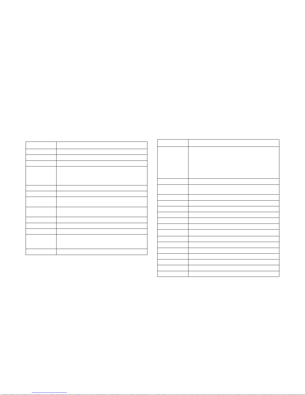
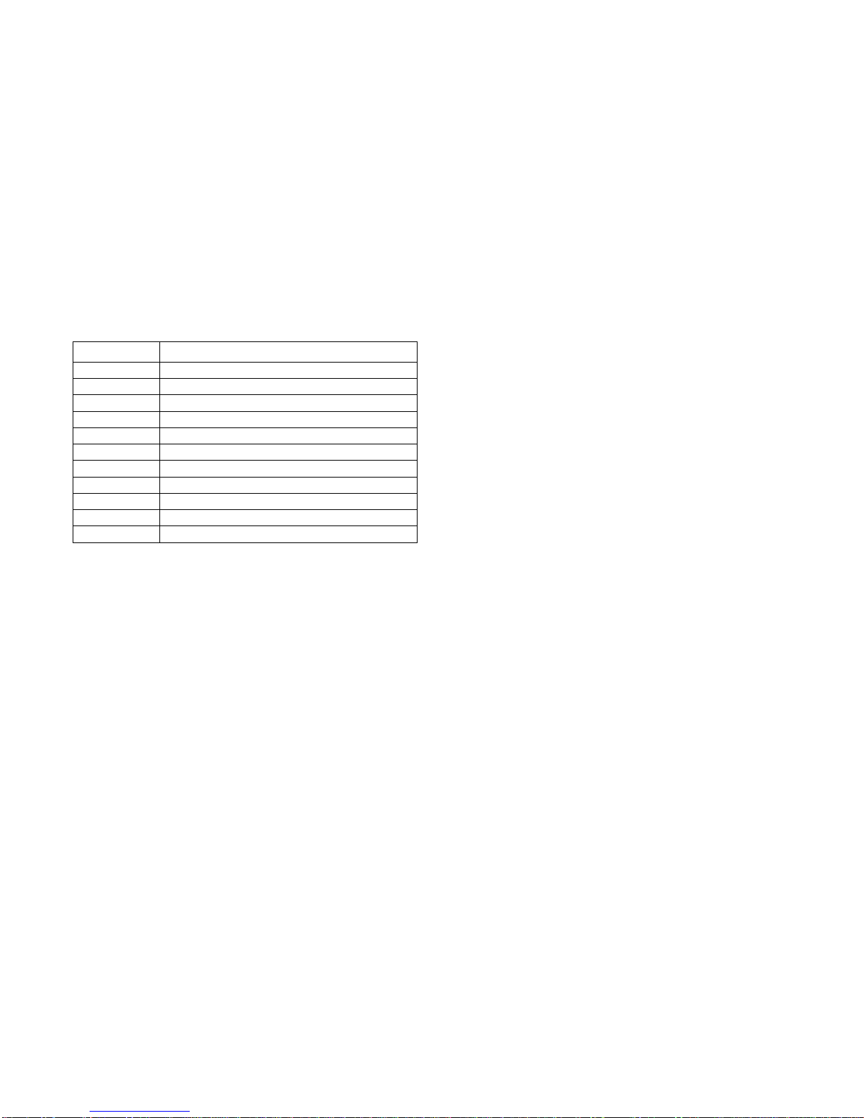
Acronyms
TERM DEFINITION
A/D Analog to Digital
ACPI Advanced Configuration and Power Interface
ASF Alerting Standard Forum
Asserted
Active-high (positive true) signals are asserted when in
the high electrical state (near power potential). Activelow (negative true) signals are asserted when in the
low electrical state (near ground potential).
BIOS Basic Input/Output System
BIST Built-In Self Test
BMC
At the heart of the IPMI architecture is a microcontroller
called the Baseboard management controller (BMC)
Bridge
Circuitry connecting one computer bus to another,
allowing an agent on one to access the other
BSP Bootstrap processor
Byte 8-bit quantity
CLI Command Line Interface
CMOS
In terms of this specification, this describes the PC-AT
compatible region of battery-backed 128 bytes of memory, which normally resides on the baseboard
CPU Central Processing Unit
Deasserted
A signal is deasserted when in the inactive state.
Active-low signal names have “_L” appended to the
end of the signal mnemonic. Active-high signal names
have no “_L” suffix. To reduce confusion when referring
to active-high and active-low signals, the terms one/
zero, high/low, and true/false are not used when
describing signal states.
DTC Data Transfer Controller
EEPROM
Electrically Erasable Programmable Read-Only Memory
EMP Emergency Management Port
FRU Field Replaceable Unit
GB 1024 MB.
GPIO General Purpose Input/Out
HSC Hot-Swap Controller
Hz Hertz (1 cycle/second)
I
2
C
Inter-Integrated Circuit bus
IANA Internet Assigned Numbers Authority
IBF Input buffer
ICH I/O Controller Hub
ICMB Intelligent Chassis Management Bus
IERR Internal Error
IP Internet Protocol
IPMB Intelligent Platform Management Bus
T
ERM DEFINITION
Page 18

ACRONYMS
XVII
IPMI Intelligent Platform Management Interface
ITP In-Target Probe
KB 1024 bytes.
KCS Keyboard Controller Style
KVM Keyboard, Video, Mouse
LAN Local Area Network
LCD Liquid Crystal Display
LCT Lower Critical Threshold
LED Light Emitting Diode
LNCT Lower Non-Critical Threshold
LNRT Lower Non-Recoverable Threshold
LPC Low Pin Count
LSI Large Scale Integration
LUN Logical Unit Number
MAC Media Access Control
MB 1024 KB
MD2 Message Digest 2 – Hashing Algorithm
MD5
Message Digest 5 – Hashing Algorithm – Higher Security
Ms Milliseconds
Mux Multiplexer
NIC Network Interface Card
NMI Non-maskable Interrupt
NM Node Management
OBF Output buffer
OEM Original Equipment Manufacturer
T
ERM DEFINITION
Ohm Unit of electrical resistance
PDB Power Distribution Board
PEF Platform Event Filtering
PEP Platform Event Paging
PERR Parity Error
POH Power-On Hours
POST Power-On Self Test
PWM Pulse Width Modulation
RAC Remote Access Card
RAM Random Access Memory
RMCP Remote Management Control Protocol
ROM Read Only Memory
RTC
Real-Time Clock. Component of the chipset on the
baseboard.
RTOS Real Time Operation System
SCI Serial Communication Interface
SDC SCSI Daughter Card
SDR Sensor Data Record
SEEPROM
Serial Electrically Erasable Programmable Read-Only
Memory
SEL System Event Log
SERR System Error
SMBus
A two-wire interface based on the I
2
C protocol. The
SMBus is a low-speed bus that provides positive
addressing for devices, as well as bus arbitration
SMI
Server Management Interrupt. SMI is the highest priority non-maskable interrupt
T
ERM DEFINITION
Page 19
ACRONYMS
XVIII
SMM Server Management Mode
SMS Server Management Software
SNMP Simple Network Management Protocol
SOL Serial Over LAN
UART Universal Asynchronous Receiver/Transmitter
UCT Upper Critical Threshold
UDP User Datagram Protocol
UNCT Upper Non-Critical Threshold
UNRT Upper Non-Recoverable Threshold
WDT Watchdog Timer
Word 16-bit quantity
T
ERM DEFINITION
Page 20

SAFETY INFORMATION
XIX
Safety Information
Important Safety Instructions
Read all caution and safety statements in this document before
performing any of the instructions.
Warnings
Heed safety instructions: Before working with the server,
whether using this manual or any other resource as a reference, pay close attention to the safety instructions. Adhere to
the assembly instructions in this manual to ensure and maintain
compliance with existing product certifications and approvals.
Use only the described, regulated components specified in this
manual. Use of other products / components will void the UL
listing and other regulatory approvals of the product and will
most likely result in non-compliance with product regulations in
the region(s) in which the product is sold.
System power on/off: The power button DOES NOT turn off
the system AC power. To remove power from system, you must
unplug the AC power cord from the wall outlet. Make sure the
AC power cord is unplugged before opening the chassis, adding, or removing any components.
Hazardous conditions, devices and cables: Hazardous electrical conditions may be present on power, telephone, and communication cables. Turn off the server and disconnect the
power cord, telecommunications systems, networks, and
modems attached to the server before opening it. Otherwise,
personal injury or equipment damage can result.
Electrostatic discharge (ESD) and ESD protection: ESD can
damage drives, boards, and other parts. We recommend that
you perform all procedures in this chapter only at an ESD workstation. If one is not available, provide some ESD protection by
wearing an antistatic wrist strap attached to chassis ground any
unpainted metal surface on the server when handling parts.
ESD and handling boards: Always handle boards carefully.
They can be extremely sensitive to electrostatic discharge
(ESD). Hold boards only by their edges. After removing a board
from its protective wrapper or from the server, place the board
component side up on a grounded, static free surface. Use a
conductive foam pad if available but not the board wrapper. Do
not slide board over any surface.
Installing or removing jumpers: A jumper is a small plastic
encased conductor that slips over two jumper pins. Some jumpers have a small tab on top that can be gripped with fingertips
or with a pair of fine needle nosed pliers. If the jumpers do not
have such a tab, take care when using needle nosed pliers to
remove or install a jumper; grip the narrow sides of the jumper
Page 21

SAFETY INFORMATION
XX
with the pliers, never the wide sides. Gripping the wide sides
can damage the contacts inside the jumper, causing intermittent
problems with the function controlled by that jumper. Take care
to grip with, but not squeeze, the pliers or other tool used to
remove a jumper, or the pins on the board may bend or break.
Page 22
REVISION HISTORY
XXI
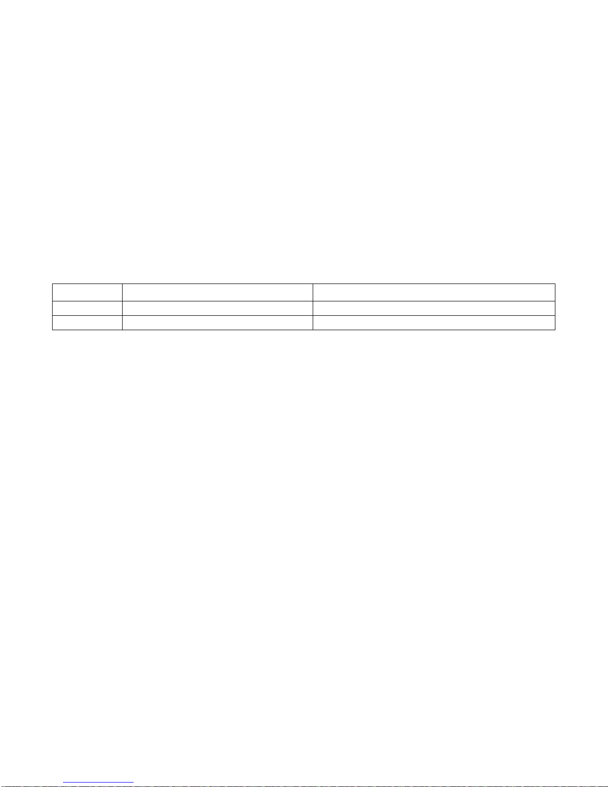
Revision History
Refer to the table below for the updates made to this manual.
Copyright
Copyright © 2014 Quanta Computer Inc. This publication,
including all photographs, illustrations and software, is protected under international copyright laws, with all rights
reserved. Neither this manual, nor any of the material contained
herein, may be reproduced without the express written consent
of the manufacturer. All trademarks and logos are copyrights of
their respective owners.
Version 1.2.0 / April 14, 2014
Disclaimer
The information in this document is subject to change without
notice. The manufacturer makes no representations or warranties with respect to the contents hereof and specifically dis-
claims any implied warranties of merchantability or fitness for
any particular purpose. Furthermore, the manufacturer reserves
the right to revise this publication and to make changes from
time to time in the content hereof without obligation of the manufacturer to notify any person of such revision or changes.
For the latest information and updates please refer to
www.QuantaQCT.com
All the illustrations in this technical guide are for reference only
and are subject to change without prior notice.
DATE CHAPTER UPDATES
Page 23

REVISION HISTORY
XXII
About the Book
This manual is written for system technicians who are responsible for troubleshooting, upgrading, and repairing the server
chassis. This document provides an overview of the hardware
features of the chassis, troubleshooting information, and
instructions on how to add and replace components of the
multi-node server series. The document also provides information on the BIOS, and Baseboard Management Controller
(BMC).
For the latest version of this manual, see
www.QuantaQCT.com.
Page 24

About the Server
Chapter 1
Page 25
ABOUT THE SERVER INTRODUCTION
1-1
1.1. Introduction
Main Features
Quanta STRATOS S200-X12TS is a 2-socket general purpose
1U server, supporting two Intel® Xeon® processor E5-2400 /
E5-2400 v2 product family and twelve DDR3 DIMM slots. It is
designed with optimized cost suitable for fast growing small and
medium businesses who need more performance head rooms
to scale up from 1-socket platforms.
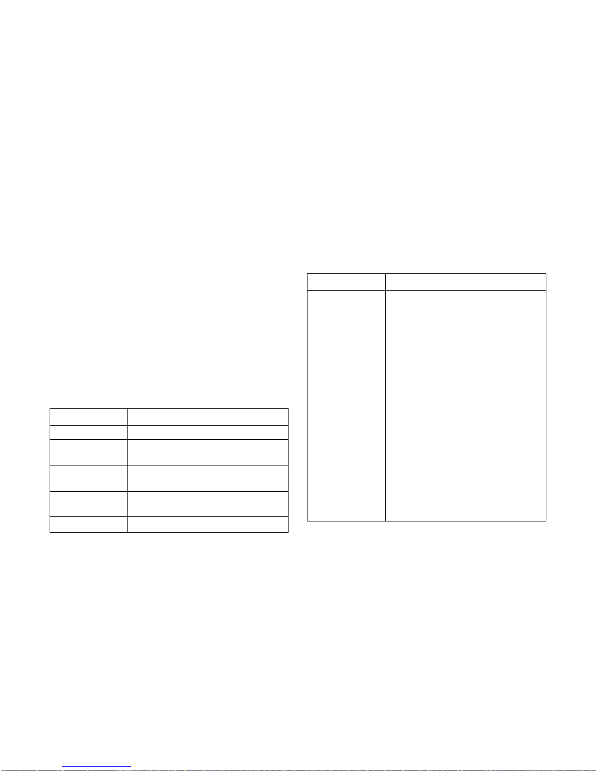
Specifications
S200-X12TS Specification
SPECIFICATION DESCRIPTION
Form Factor X1 (1U Chassis)
Chassis Size (L x W x
H)
728 mm x 438 mm x 43.2 mm
28.66" x 17.24" x 1.7"
Mainboard Size (W x
L )
165 mm x 416.6 mm
6.5" x 16.4" (half-width)
Processor
(2) Intel
®
Xeon® processor E5-2400 / E5-2400
v2 product family per node, up to 95W
Chipset
Intel
®
C602
SAS Controller
2.5” 1 to 1 SKU
LSI SAS controller
Quanta LSISAS 2008 or 2308 Mezzanine
card
Quanta LSISAS 2108 or 2208 Mezzanine
card (optional)
3.5” 1 to 1 SKU
Intel
®
SAS controller
Intel
®
C602 upgrade ROM #1 (optional)
Intel
®
C602 upgrade ROM #2 (optional)
or
LSI SAS controller
Quanta LSISAS 2008/2308/2108/2208
Mezzanine card (optional)
2.5” Expander SKU
[LSI SAS controller]
Quanta LSISAS 2008 or 2308 Mezzanine
card
Quanta LSISAS 2108 or 2208 Mezzanine
card (optional)
S200-X12TS Specification (Continued)
SPECIFICATION DESCRIPTION
Page 26
ABOUT THE SERVER MAIN FEATURES
1-2
Memory
(12) DDR3 800/1066/1333/1600 MHz
ECC RDIMM slots per node, up to 384 GB
Storage
2.5” 1 to 1 SKU
(10) 2.5" hot-plugable HDD(Mezz *8+ AHCI
*2 6Gb) + (2) fixed SATAII (AHCI 3Gb) or
SSD (AHCI 3Gb)
(1) USB Flash Module for OS installation per
node (optional)
3.5” 1 to 1 SKU
(4) 3.5" hot-plugable HDD(SCU 3Gb) + (2)
fixed SATAIII (AHCI 6Gb) or SSD (AHCI 6Gb)
+ (1) fixed SSD front end
(1) USB Flash Module for OS installation per
node (optional)
2.5” Expander SKU
(10) 2.5" hot-plugable SATA/SAS
HDD(expander 6Gb) + (2) fixed SATAII (AHCI
6Gb) or SSD (AHCI 6Gb)
(1) USB Flash Module for OS installation per
node (optional)
HDD Backplane
2.5” 1 to 1 SKU / 3.5” 1 to 1 SKU
1 to 1
2.5” Expander SKU
Expander
S200-X12TS Specification (Continued)
SPECIFICATION DESCRIPTION
PCIe Expansion Slot
(1) Riser w/ Linking - PCIe x8 G2 riser slot
10GbE SFP+ Mezzanine card slot & Low profile x8 slot
(1) PCIe x8 G2 Quanta LSISAS/RAID Mezza-
nine card slot
SW RAID Options
2.5” 1 to 1 SKU / 2.5” Expander SKU
LSI SW RAID
Quanta LSISAS 2008/2308 mezzanine
card for RAID 0/1/10
3.5” 1 to 1 SKU
Intel SW RAID
Intel RSTe SATA RAID 0/1/10/5
Intel C602 upgrade ROM #1 SAS RAID 0/
1/10 (optional for SCU)
Intel C602 upgrade ROM #2 SAS RAID 0/
1/10/5 (optional for SCU)
or
LSI SW RAID
Quanta LSISAS 2008/2308 mezzanine
card for RAID 0/1/10 (optional)
S200-X12TS Specification (Continued)
SPECIFICATION DESCRIPTION
Page 27
ABOUT THE SERVER MAIN FEATURES
1-3
HW RAID Options
2.5” 1 to 1 SKU / 3.5” 1 to 1 SKU
Quanta LSISAS2108/2208 PD-8 mezzanine
card for RAID 0/1/10/5 (optional)
Quanta LSISAS2108/2208 PD-8 mezzanine
card + LSI RAID 6 Key for RAID 0/1/10/5/6/
50/60 (optional)
2.5” Expander SKU
Quanta LSISAS2108/2208 PD-16 mezzanine
card for RAID 0/1/10/5 (optional)
Quanta LSISAS2108/2208 PD-16 mezzanine
card + LSI RAID 6 Key for RAID 0/1/10/5/6/
50/60 (optional)
Network
(2) Intel
®
Powerville I350GbE RJ45 ports
(1) Quanta 10GbE SFP+ dual port mezza-
nine card (optional)
Management Port
(1) Dedicated 10/100 BASE-T RJ45 management port per node
Integrated Graphics
BMC
Aspeed AST2300 8MB DDR3 Video memory
Rear I/O
(2) USB 2.0 ports
(1) VGA port
(1) RS232 serial Port
(2) GbE RJ45 ports
(1) 10/100 BASE-T RJ45 management port
S200-X12TS Specification (Continued)
SPECIFICATION DESCRIPTION
Power Supply
(1) 750W high efficiency PSU
(1) 750W high efficiency redundant PSU
(optional)
TPM NA
RoHS Yes
Intel Node Management support
Yes
System Management
IPMI v2.0 Compliant, on board "KVM over IP"
support
S200-X12TS Specification (Continued)
SPECIFICATION DESCRIPTION
Page 28

ABOUT THE SERVER PACKAGE CONTENTS
1-4
1.2. Package Contents
The following list includes the package components:
1U chassis system
Mainboard modules
2 x Processor heatsinks
Power supply
Power cord (optional)
CD (technical guide included)
Rail kit
Important:
Server configurations may vary. Confirm your sales representative for the exact items included in your order.
Page 29
ABOUT THE SERVER A TOUR OF THE SYSTEM
1-5
1.3. A Tour of the System
System Overview
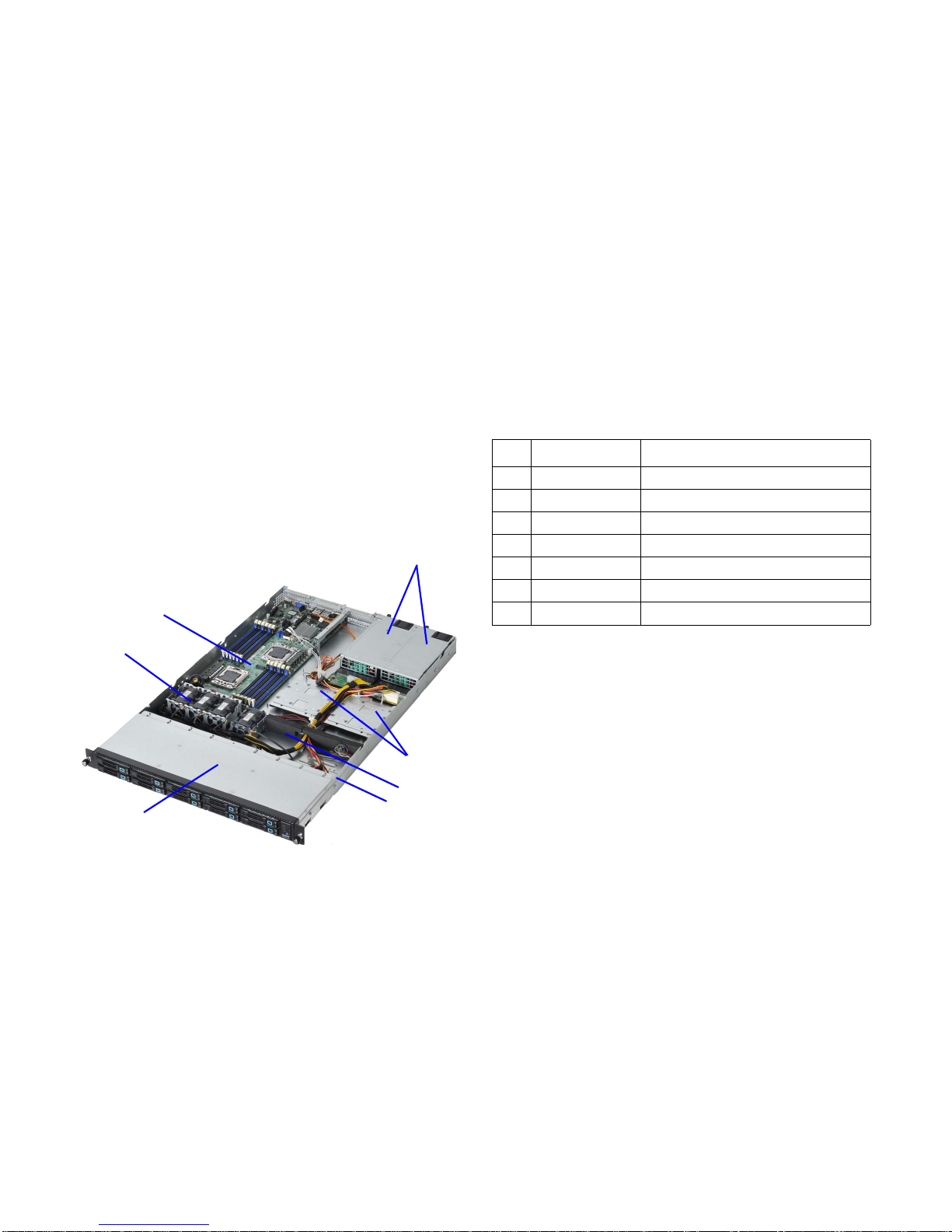
The S200-X12TS is available as a 2.5” or a 3.5” form factor.
2.5” HDD System
2.5” HDD System Component Overview
1
2
4
5
6
7
3
2.5” SKU System Component Description
NO.ITEM DESCRIPTION
1 PSUs 2x power supply units (PSU)
2 2.5” or 3.5” HDD 2.5” or 3.5” fixed HDDs
3 Battery System battery
4 Chassis System chassis
5 2.5 HDDs 2.5” hard disk drive (HDD) cage
6 System fan 4x system fan modules
7 MB module Mainboard module
Page 30
ABOUT THE SERVER SYSTEM FRONT FEATURES
1-6
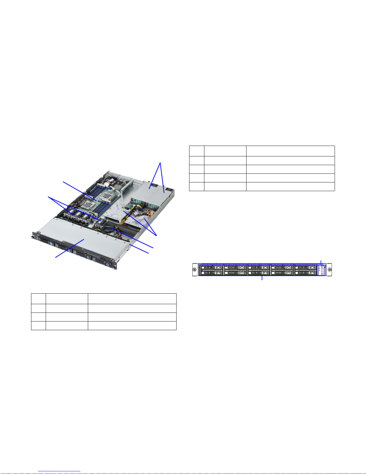
3.5” HDD System
3.5” HDD System Component Description
System Front Features
Configuration
2.5” HDD Configuration
2.5” HDD Configuration
3.5” SKU System Component Description
NO.ITEM DESCRIPTION
1 PSUs (2) power supply units (PSU)
2 2.5” or 3.5” HDD 2.5” or 3.5” fixed HDDs
3 Battery System battery
1
2
4
5
6
7
3
4 Chassis System chassis
5 3.5 HDDs 3.5” hard disk drive (HDD) cage
6 System fan (4) System fan modules
7 MB module Mainboard module
3.5” SKU System Component Description (Continued)
NO.ITEM DESCRIPTION
1
2
Page 31

ABOUT THE SERVER SYSTEM FRONT FEATURES
1-7
3.5” HDD Configuration
3.5” HDD Configuration
Control Panel
2.5” HDD SKU Control Panel
2.5” HDD SKU Control Panel Features
System Configuration
ITEM NAME DESCRIPTION
1 Control Panel Control system
2 HDD Bays HDDs arrays
1
2
2.5” HDD SKU Control Panel Features
ITEM ICON NAME DESCRIPTION
1 Event LED
Amber Blinking:
Critical failure: fan, voltage, temperature state
Non-critial failure: fan, voltage, temperature state, CPU, thermal trip
Off: SEL cleared, DC off, last pending
warning/error de-asserted
2 LAN1/2 LED
Green On, link
Green Blinking, LAN access
1
2
3
4
Page 32

ABOUT THE SERVER SYSTEM FRONT FEATURES
1-8
3.5” HDD SKU Control Panel
3.5” HDD SKU Control Panel Features
3
Power Button with LED
Green On
Based on System Off, Push Button to
PSU and System On
Based on System On, Push Button to
PSU and System Off
4
ID button
with LED
Blue On, selected unit ID
Off, no ID requested
3.5” HDD SKU Control Panel Features
ITEM ICON NAME DESCRIPTION
1
Front USB
ports
Connect USB devices to these ports
2.5” HDD SKU Control Panel Features (Continued)
ITEM ICON NAME DESCRIPTION
123 456 7
2
Reset Button with
LED
Base system On
Push button to Reset system
3MGMT LED
Green On, link
Green Blinking, LAN access
4
LAN 2/1
LED
Green On, link Green Blinking, LAN
access
5
HDD Activity LED
Green Blinking, HDD access Off, no
access
6 Event LED
Amber Blinking:
Critical failure: fan, voltage, temperature
state
Non-critial failure: fan, voltage, temperature state, CPU, thermal trip
Off: SEL cleared, DC Off, last pending
warning/error de-asserted
7
ID Button
with LED
Blue On, selected unit ID
Off, no ID requested
8
Power button with
LED
Green On
Based on System Off, Push Button to
PSU and System On
Based on System On, Push Button to
PSU and System off
3.5” HDD SKU Control Panel Features (Continued)
ITEM ICON NAME DESCRIPTION
Page 33

ABOUT THE SERVER SYSTEM REAR FEATURES
1-9
System Rear Features
Configuration
System Rear Configuration
I/O Features
System Rear I/O Features
System Rear Configuration
NO.ITEM DESCRIPTION
1
Main Power Supply Unit
Main power supply unit (PSU)
2 Dummy PSU Dummy PSU
3 Mainboard Mainboard (MB)
2
1 3
S200-X12TS System I/O Features
ITEM FEATURE DESCRIPTION
1 10GbE SFP+ mezzanine Port Optional
2 PSU Power supply unit
3 Serial port
Connect serial devices to this
port
4 LAN LAN access
5 Dedicated Management LAN Port
6 VGA port Connect a monitor to this port
7USB port
USB ports (2.0 compliant)
Note:
The width of the USB drive
needs to be lower than 17mm
to avoid interfering with the use
of the VGA port.
8 Power button On/Off power to the module
1
847623
5
Page 34

ABOUT THE SERVER POWER SUB-SYSTEM
1-10
Power Sub-System
PSU Description
A system can have two power supply units (PSU). The primary
PSU and a redundant backup. The redundant backup is
optional.
LED Status Definitions
I/O LED Description
Power Supply Units by Model
MODEL PSU AC INPUT
S200-X12TS
(1) 750W high efficiency PSU,
100-240VAC 50/60Hz
110/220V
Note:
To use mainboard modules other than the models listed make
sure to contact the system dealer first and obtain authorized
approval.
PSU
I/O LED Description - 1GbE LAN
ICON NAME COLOR
CONDITIONDESCRIPTIO
N
Identification LED
Blue On
Unit
selected for
identification
-- Off
No identification
requested
Page 35

ABOUT THE SERVER LED STATUS DEFINITIONS
1-11
LAN1
LED
(Upper)
Link/Act
Green On LAN Link
Green Black Blinking
LAN access
(off when
there is traffic)
-- Off Disconnect
Speed
Green On
Link speed
is 100Mbits/
sec
Amber On
Link speed
is
1000Mbits/
sec
-- Off
Off, link
speed is
10Mbits/sec
I/O LED Description - 1GbE LAN (Continued)
ICON NAME COLOR
CONDITIONDESCRIPTIO
N
LAN2
LED
(Lower)
Link/Act
Green On LAN Link
Green Black Blinking
LAN access
(off when
there is traffic)
-- Off Disconnect
Speed
Green On
Link speed
is 100Mbits/
sec
Amber On
Link speed
is
1000Mbits/
sec
-- Off
OFF, link
speed is
10Mbits/sec
Service
Port
(LAN 3)
LED
Link/Act
Green On LAN Link
Green Black Blinking
LAN access
(off when
there is traffic)
-- Off Disconnect
Speed Green On
Link speed
is 10/100/
1000Mbits/
sec
I/O LED Description - 1GbE LAN (Continued)
ICON NAME COLOR
CONDITIONDESCRIPTIO
N
Page 36

ABOUT THE SERVER LED STATUS DEFINITIONS
1-12
I/O LED Description - 10GbE LAN
ICON NAME COLOR
CONDITIONDESCRIPTIO
N
Identification LED
Blue On
Unit
selected for
identification
-- Off
No identification
requested
LAN1
LED
(Upper)
Link/Act
Green On LAN Link
Green Black Blinking
LAN access
(off when
there is traffic)
-- Off Disconnect
Speed
Blue On
Link speed
is 10Gbits/
sec
Amber On
Link speed
is 1Gbits/
sec
-- Off
Link speed
is 10/
100Mbits/
sec
LAN2
LED
(Lower)
Link/Act
Green On LAN Link
Green Black Blinking
LAN access
(off when
there is traffic)
-- Off Disconnect
Speed
Blue On
Link speed
is 10Gbits/
sec
Amber On
Link speed
is 1Gbits/
sec
-- Off
Link speed
is 10/
100Mbits/
sec
I/O LED Description - 10GbE LAN (Continued)
ICON NAME COLOR
CONDITIONDESCRIPTIO
N
Page 37

ABOUT THE SERVER LED STATUS DEFINITIONS
1-13
LAN LED
The system mainboard has one I350GbE Ethernet controller
and two 1GbE ports. Each RJ45 connector has two built-in
LEDs. See the following illustration and table for details.
RJ45 LAN Connector
Service
Port
(LAN 3)
LED
Link/Act
Green On LAN Link
Green Black Blinking
LAN access
(off when
there is traffic)
-- Off Disconnect
Speed
Green On
Link speed
is 10/100/
1000Mbits/
sec
-- Off
I/O LED Description - 10GbE LAN (Continued)
ICON NAME COLOR
CONDITIONDESCRIPTIO
N
1GbE and 10GbE LED Description
10GbE CHIP ONBOARD 1GbE CHIP ONBOARD
Link Activity Link Activity
1GbE LED Amber
Green Blinking
Amber
Green Blinking
100M Off
Green Blinking
Green
Green Blinking
Link
Activity
PIN 1
Location
Page 38

ABOUT THE SERVER LED STATUS DEFINITIONS
1-14
Control Panel LED
3.5” HDD SKU Control Panel LED
3.5” HDD SKU Control Panel LED
3.5 SKU LED FUNCTION AND BEHAVIOR
ICON NAME COLOR CONDIT ION DESCRIPTION
Power
LED
Green On System power on
-- Off System power off
Identificaiton
Blue On
Unit selected for identification
-- Off
No identification
requested
Fault
LED
Amber Blinking
Critical failure: critical
fan, voltage, temperature state
Non-critical failure: noncritical fan, voltage,
temperature state, CPU
thermal trip
-- Off
SEL cleared
DC off
Last pending warning or
error has been deasserted
HDD
Activity
Green Blinking
Hard disk drive access
(only on board SATA
port)
-- Off No access (non-SAS)
LAN1
LED
Green On Link
Green Blinking
LAN access (off when
there is traffic)
LAN2
LED
Green On Link
Green Blinking
LAN access (off when
there is traffic)
Service
LED
Green On Link
Green Blinking
LAN access (off when
there is traffic)
Note:
LAN LED on 3.5” system is an Activity/Link LED which turns
on when link is established and flashes when there is TX/RX
activity.
When system at sleep mode, the Power LED will still green
on.
3.5” HDD SKU Control Panel LED (Continued)
3.5 SKU LED FUNCTION AND BEHAVIOR
ICON NAME COLOR CONDITION DESCRIPTION
Page 39

ABOUT THE SERVER LED STATUS DEFINITIONS
1-15
2.5” HDD SKU Control Panel LED
2.5” HDD SKU Control Panel LED
3.5 SKU LED FUNCTION AND BEHAVIOR
ICON NAME COLOR CONDITION DESCRIPTION
Power
LED
Green On System power on
-- Off System power off
Identificaiton
Blue On
Unit selected for identification
-- Off
No identification
requested
Fault
LED
Amber Blinking
Critical failure: critical
fan, voltage, temperature state
Non-critical failure: noncritical fan, voltage,
temperature state, CPU
thermal trip
-- Off
SEL cleared
DC off
Last pending warning or
error has been deasserted
LAN1
LED
Green Blinking LAN access
-- On Link
LAN2
LED
Green Blinking LAN access
-- On Link
Note:
When the system is at sleep mode, the Power LED will be still
On (green).
2.5” HDD SKU Control Panel LED (Continued)
3.5 SKU LED FUNCTION AND BEHAVIOR
ICON NAME COLOR CONDITION DESCRIPTION
Page 40

ABOUT THE SERVER LED STATUS DEFINITIONS
1-16
HDD LED
3.5” HDD SKU One to One AMI LED Behavior
Note:
SES-2 command card is not supported.
3.5” HDD SKU One to One AMI LED Behavior
SIMPLE LED PATTERN
SLOT/DEVICE STATES HDD ACCESS
IDENTIFICAITON
STATUS LED
(G
REEN)
F
AULT LED
(R
ED)
A
CTIVE LED
(D
EEP GREEN)
Drive Online
Green On continuously
Off
HDD R/W
access the
Active LED
On
HDD no R/
W Access
the Active
LED Off
Slot Empty Off Off Off
Note:
LSI 9210-8i and SAS2008, SAS2308 Mezzanine card no
RAID mode, only support Simple LED pattern.
If SW RAID cards no crate RAID mode, only support Simple
LED pattern.
On board AHCI/SCU Port (PCH) support Simple LED pat-
tern.
Page 41

ABOUT THE SERVER LED STATUS DEFINITIONS
1-17
3.5” HDD SKU One to One Backplane LED Behavior
The 4-disk backplane supports up to 4 drive slots and provides the LEDs that are used to light the HDD status indicators as in the following table.
3.5” HDD SKU One to One Backplane LED Pattern
ONE TO ONE BACKPLANE LED PATTERN
SLOT/DEVICE STATES (RAID STATES)
I
DENTIFICAITON
SLOT/DEVICE STATES (RAID
S
TATES)
S
TATUS LED (GREEN)FAULT LED (RED)ACTIVE LED (DEEP GREEN)
Device / Identify / Prepare for
Removal
The slot is being identified
because of a user request
(either a disk identify or a
Preparing for Removal was
requested)
On 250 msec
Off 250 msec
Off
HDD R/W Access the
Active LED On
HDD no R/W Access the
Active LED Off
Control by HW Direct to
HDD active pin
Device Failed
The storage controller can
no longer access or control
(read/write to) the disk
because it has detected an
unrecoverable fault (after it
has completed its error handling) on the disk
Off
On 250 msec
Off 250 msec
Predicted Fail (Smart Function)
Indicates that a predictive
failure event has been
reported by the disk
On 500 msec
Off 500 msec
Off 1000 msec
Off 500 msec
On 500 msec
Off 1000 msec
Page 42

ABOUT THE SERVER LED STATUS DEFINITIONS
1-18
Device Rebuilding
The disk is being written to,
create a virtual disk
On 400 msec
Off 100 msec
Off
HDD R/W Access the
Active LED On
HDD no R/W Access the
Active LED Off
Control by HW Direct to
HDD active pin
Rebuild Abort
The disk has been spun
down by a user request (Prepare to Remove operation),
or had a rebuild operation on
it aborted by a user action or
due to any reason other than
a disk failure
On 3000 msec
Off 9000 msec
On 6000 msec
Off 3000 msec
Off 3000 msec
Drive Online
The disk is in any of the following states:
Online
Ready
Hotspare
Foreign disk
On Off
Slot Empty
The slot is empty, an unsupported disk is present, the
disk has been spun down for
removal (Ready for
Removal), or a new disk has
been inserted (the disk PHY
not ready), and the state has
not been updated by the
storage controller
Off Off Off
3.5” HDD SKU One to One Backplane LED Pattern
ONE TO ONE BACKPLANE LED PATTERN
SLOT/DEVICE STATES (RAID STATES)
I
DENTIFICAITON
SLOT/DEVICE STATES (RAID
S
TATES)
S
TATUS LED (GREEN)FAULT LED (RED)ACTIVE LED (DEEP GREEN)
Page 43

ABOUT THE SERVER LED STATUS DEFINITIONS
1-19
2.5” HDD SKU Simple LED
Using on board AHCI/SCU Port (PCH)
Note:
The LED pattern follows the DCS LED pattern spec. design.
The LED pattern is only for MegaRAID card.
SAS2008, SAS2308 Mezzanine card no support Full LED, so only support Simple LED mode.
2.5” HDD SKU Simple LED
SIMPLE LED PATTERN
SLOT/DEVICE STATES H DD ACCESS
INDICATION
STATUS LED
(G
REEN)
F
AULT LED
(R
ED)
A
CTIVE LED
(D
EEP GREEN)
Drive Online
Green on continuously
Off
HDD R/W
Access the
Active LED
On
HDD no R/W
Access the
Active LED
Off
Control by
HW Direct to
HDD active
pin
Slot Empty Off Off Off
Page 44

ABOUT THE SERVER LED STATUS DEFINITIONS
1-20
2.5” HDD SKU One to One Backplane (2.5”x10 SKU)
Note:
Applies to Quanta SAS2008 and SAS2108 Mezzanine card.
The pattern only on the RAID mode.
The backplane included AMI 9086 Backplane Controller, LED decode from SGPIO singles.
2.5” HDD SKU One to One Backplane LED Pattern (2.5” x10 SKU)
ONE TO ONE BACKPLANE LED PATTERN
SLOT/DEVICE STATES (RAID STATES)
I
DENTIFICAITON
SLOT/DEVICE STATES (RAID
S
TATES)
S
TATUS LED (GREEN)FAULT LED (RED)ACTIVE LED (DEEP GREEN)
Device / Identify / Prepare for
Removal
The slot is being identified
because of a user request
(either a disk identify or a
Preparing for Removal was
requested)
On 250 msec
Off 250 msec
Off Blinking when activity
Device Failed
The storage controller can
no longer access or control
(read/write to) the disk
because it has detected an
unrecoverable fault (after it
has completed its error handling) on the disk
Off
On 150 msec
Off 150 msec
Off
Predicted Fail (Smart Function)
Indicates that a predictive
failure event has been
reported by the disk
On 500 msec
Off 500 msec
Off 1000 msec
Off 500 msec
On 500 msec
Off 1000 msec
Blinking when activity
Page 45

ABOUT THE SERVER LED STATUS DEFINITIONS
1-21
Device Rebuilding
The disk is being written to,
create a virtual disk
On 400 msec
Off 100 msec
Off Blinking when activity
Rebuild Abort
The disk has been spun
down by a user request (Prepare to Remove operation),
or had a rebuild operation on
it aborted by a user action or
due to any reason other than
a disk failure
On 3000 msec
Off 9000 msec
On 6000 msec
Off 3000 msec
Off 3000 msec
Off
Drive Online
The disk is in any of the following states:
Online
Ready
Hotspare
Foreign disk
On Off Blinking when activity
Slot Empty
The slot is empty, an unsupported disk is present, the
disk has been spun down for
removal (Ready for
Removal), or a new disk has
been inserted (the disk PHY
not ready), and the state has
not been updated by the
storage controller
Off Off Off
2.5” HDD SKU One to One Backplane LED Pattern (2.5” x10 SKU) (Continued)
ONE TO ONE BACKPLANE LED PATTERN
SLOT/DEVICE STATES (RAID STATES)
I
DENTIFICAITON
SLOT/DEVICE STATES (RAID
S
TATES)
S
TATUS LED (GREEN)FAULT LED (RED)ACTIVE LED (DEEP GREEN)
Page 46

ABOUT THE SERVER LED STATUS DEFINITIONS
1-22
2.5” HDD SKU Expander LED Mode (2.5” x10 SKU)
The 10-disks backplane supports up to 10 drive slots and provides the LEDs that are used to light the HDD status indicators as
shown in the following table.
2.5” HDD SKU Expander LED Mode (2.5” x10 SKU)
EXPANDER LED PATTERN
SLOT/DEVICE STATES (RAID STATES) HDD ACCESS
IDENTIFICAITON
SES-2
C
OMMAND
SLOT/DEVICE STATES (RAID STATES)
S
TATUS LED
(G
REEN)
F
AULT LED
(R
ED)
A
CTIVE LED (DEEP GREEN)
Device Identify RQST Ident
The slot is being identified because of
a user request
On 250 msec
Off 250 msec
Off
HDD R/W access the
Active LED On
HDD no R/W access the
Active LED Off
Control by H/W direct to
HDD active pin
Device Failed RQST FAULT
The storage controller can no longer
access or control (read/write to) the
disk because it has detected an unrecoverable fault (after it has completed
its error handling) on the disk
Off
On 150
msec
Off 150
msec
In Critical Array
RQST in Crit
Array
The virtual disk had one disk Read or
Write error, and RAID recovery function enabled
Off
On 250
msec
Off 250
msec
In Failed Array
RQST In Failed
Array
The virtual disk had over one disk
Read or Write error, and RAID recovery function failure
Off
On 250
msec
Off 250
msec
Page 47

ABOUT THE SERVER LED STATUS DEFINITIONS
1-23
Predicted Fail (Smart
Function)
PRDFAIL
Indicates that a predictive failure event
has been reported by the disk
On 500 msec
Off 500 msec
Off 1000 msec
Off 500
msec
On 500
msec
Off 1000
msec
HDD R/W access the
Active LED On
HDD no R/W access the
Active LED Off
Control by H/W direct to
HDD active pin
Device Rebuilt/Remap
RQST
REBUID/
REMAP
The disk is being written to make a virtual disk redundant
On 400 msec
Off 100 msec
Off
Rebuild/Remap Abort
RQST R/R
ABORT
The disk has been spun down by a
user request (Prepare to Remove
operation), or had a rebuild operation
on it aborted by a user action or due to
any reason other than a disk failure
On 3000 msec
Off 9000 msec
Off 6000
msec
On 3000
msec
Off 3000
msec
Prepare for Removal
RQST
REMOVE
The slot is being Preparing for
Removal because of a user request
On 250 msec
Off 250 msec
Off
Drive Online
By Expabder
control
The disk is in any of the following
states:
Online
Ready
Hotspare
Foreign disk
On Off
2.5” HDD SKU Expander LED Mode (2.5” x10 SKU)
EXPANDER LED PATTERN
SLOT/DEVICE STATES (RAID STATES) HDD ACCESS
IDENTIFICAITON
SES-2
C
OMMAND
SLOT/DEVICE STATES (RAID STATES)
S
TATUS LED
(G
REEN)
F
AULT LED
(R
ED)
A
CTIVE LED (DEEP GREEN)
Page 48

ABOUT THE SERVER LED STATUS DEFINITIONS
1-24
Slot Empty
By Expabder
control
The slot is empty, an unsupported disk
is present, the disk has been spun
down for removal (Ready for
Removal), or a new disk has been
inserted (the disk PHY not ready), and
the state has not been updated by the
storage controller
Off Off Off
Note:
The LED pattern follows the DCS LED pattern spec. design.
The LED pattern only for LSI 9260-8i and MegaRAID card.
LSI 9210-8i and SAS2008, SAS2308 mezzanine cards do not fault LED, only Simple LED mode.
The Rebuild LED Will over write the RAID failed LED pattern.
If using Standard SAS HDD, the HDD Active LED by Reverse
Normal (Standby ) state the Green LED still on,
HDD access the LED blanking.
2.5” HDD SKU Expander LED Mode (2.5” x10 SKU)
EXPANDER LED PATTERN
SLOT/DEVICE STATES (RAID STATES) HDD ACCESS
IDENTIFICAITON
SES-2
C
OMMAND
SLOT/DEVICE STATES (RAID STATES)
S
TATUS LED
(G
REEN)
F
AULT LED
(R
ED)
A
CTIVE LED (DEEP GREEN)
Page 49

ABOUT THE SERVER LED STATUS DEFINITIONS
1-25
2.5” HDD SKU Simple LED Mode (2.5” x10
SKU)
For LSI 9210-8i and SAS2008, SAS2308 mezzanine card.
PSU LED
PSU LED
2.5” HDD SKU Simple LED Mode
SIMPLE LED PATTERN
SLOT/DEVICE STATES H DD ACCESS
INDICATION
STATUS LED
(G
REEN)
F
AULT LED
(R
ED)
A
CTIVE LED
(D
EEP GREEN)
Drive Online
Green on continuously
Off
HDD R/W
Access the
Active LED
On
HDD no R/W
Access the
Active LED
Off
Control by
HW Direct to
HDD active
pin
Slot Empty Off Off Off
PSU LED Description
NO FEATURE STATUS DESCRIPTION
1PSU LED
Green Normal operation
Yellow Fault
1
Page 50

Installing Hardware
Chapter 2
Page 51

INSTALLING HARDWARE SAFETY MEASURES
2-1
2.1. Safety Measures
WARNING!
Always ask for assistance to move or lift the system.
WARNING!
Only perform troubleshooting as authorized by the product
documentation, or as directed by a service and support team.
Repairs not authorized by warranty may void the warranty
and damage the system.
WARNING!
Always make sure to disconnect the system from the AC electrical source. Powering down the system DOES NOT ensure
there is no electrical activity in the system.
WARNING!
Server components and circuit boards are easily damaged by
discharges of static electricity. Working on servers that are
connected to a power supply can be extremely dangerous.
Follow the guidelines below to avoid personal injury or damage to the server.
WARNING!
Always disconnect the server from the power outlet whenever
you are working inside the server case.
!
!
!
!
!
WARNING!
Wear a grounded wrist strap. If none are available, discharge
any personal static electricity by touching the bare metal
chassis of the server case, or the bare metal body of any
other grounded device.
WARNING!
Humid environments tend to have less static electricity than
dry environments. A grounding strap is warranted whenever
danger of static electricity exists.
WARNING!
Do not touch the components on the unless it is necessary to
do so. Do not flex or stress circuit boards.
WARNING!
Leave all replacement components inside their static-proof
packaging until you are ready to use them.
!
!
!
!
Page 52

INSTALLING HARDWARE 2.5” HARD DISK DRIVES
2-2
2.2. 2.5” Hard Disk Drives
Removing a 2.5” Swappable HDD
Assembly
1. Press the tray handle button.
Releasing HDD Tray Handle
2. Pull the HDD tray handle open.
Removing HDD Assembly
3. Grasp the tray handle and pull the tray out of the system.
WARNING!
To prevent damage to the system, only use X5 HDD trays.
!
1
2
3
Page 53

INSTALLING HARDWARE REMOVING A 2.5” SWAPPABLE HDD FROM AN HDD TRAY
2-3
Removing a 2.5” Swappable HDD
from an HDD Tray
Disassembling HDD Assembly
1. Remove the screws securing the HDD to the HDD tray.
2. Remove the HDD from the HDD tray.
Installing a 2.5” Swappable HDD
Assembly
Installing HDD Assembly
1. Insert the HDD assembly into the system. Make sure the
hard drive is fully inserted.
2. Push the tray handle closed.
1
1
1
2
2
2
1
Page 54

INSTALLING HARDWARE INSTALLING A 2.5” SWAPPABLE HDD INTO AN HDD TRAY
2-4
Installing a 2.5” Swappable HDD
into an HDD Tray
Assembling HDD Tray
1. Install the HDD into the HDD tray.
2. Secure the HDD to the HDD tray with screws.
1
1
2
2
2
Page 55

INSTALLING HARDWARE REMOVING A 3.5” SWAPPABLE HDD ASSEMBLY
2-5
Removing a 3.5” Swappable HDD
Assembly
1. Press the tray handle button.
Releasing HDD Tray Handle
2. Pull the HDD tray handle open.
Removing HDD Assembly
3. Grasp the tray handle and pull the tray out of the system.
Removing a 3.5” Swappable HDD
from an HDD Tray
Disassembling 3.5” HDD assembly:
Disassembling 3.5” HDD Assembly
WARNING!
To prevent damage to the system, only use X5 HDD trays.
!
1
2
3
Note:
The 3.5” hard disk tray supports both 2.5” and 3.5” hard disks.
Page 56

INSTALLING HARDWARE INSTALLING A 3.5” SWAPPABLE HDD ASSEMBLY
2-6
Disassembling 2.5” HDD assembly:
Disassembling 2.5” HDD Assembly
1. Remove the screws securing the HDD to the HDD tray.
2. Remove the HDD from the HDD tray.
Installing a 3.5” Swappable HDD
Assembly
Installing HDD Assembly
1. Insert the HDD assembly into the system. Make sure the
hard drive is fully inserted.
2. Push the tray handle closed.
1
2
Page 57

INSTALLING HARDWARE INSTALLING A 3.5” SWAPPABLE HDD INTO AN HDD TRAY
2-7
Installing a 3.5” Swappable HDD
into an HDD Tray
Assembling 3.5” HDD assembly:
Assembling 3.5” HDD Assembly
Assembling 2.5” HDD assembly:
Assembling 2.5” HDD Assembly
1. Install the HDD into the HDD tray.
2. Secure the HDD to the HDD tray with screws.
Note:
The 3.5” hard disk tray supports both 2.5” and 3.5” hard disks.
Page 58

INSTALLING HARDWARE POWER SUPPLY UNIT
2-8
2.3. Power Supply Unit
Removing a Power Supply Unit
1. Pull the PSU handle (A) up to the open position.
Opening the PSU Handle
2. Press and hold the locking latch (B) lever.
3. Pull the PSU from the system.
Removing the PSU
Installing a Power Supply Unit
Installing a Power Supply Unit
Insert the power supply unit (PSU) into the system. Make sure
the PSU is flush with the system and the locking latch lever (B)
is locked in place.
CAUTION!
DISCONNECT THE POWER SUPPLY UNIT FROM THE POWER SOURCE
BEFORE REMOVING PSU. FAILURE TO DO SO COULD RESULT IN DAM-
AGE TO THE EQUIPMENT OR PERSONAL INJURY.
Note:
The redundant power supply unit can be replaced without shutting down the system.
!
A
B
A
B
B
Page 59

INSTALLING HARDWARE TOP COVER
2-9
2.4. Top Cover
Opening the Top Cover
4. Press the release button(s) (B) and slide the top cover
(A).
5. Lift the top cover off the chassis.
Opening Top Cover
Closing the Top Cover
1. Place the top cover (A) on the chassis.
2. Slide the top cover into place.
Closing Top Cover
B
A
A
Page 60

INSTALLING HARDWARE PROCESSOR HEAT SINKS
2-10
2.5. Processor Heat Sinks
The CPU0 and CPU1 have different types of heat sinks.
Instructions in this section discuss both types of heat sinks.
Removing a Heat Sink
Prerequisite:
Remove the top cover. See Opening the Top Cover on
page 2-9.
1. Loosen the captive screw(s) securing the heat sink to the
mainboard.
Removing the Heat Sink (CPU0)
WARNING!
The heat sink remains hot after the system has been powered
down. Allow sufficient time to cool before handling system components.
!
1
2
3
4
Page 61

INSTALLING HARDWARE INSTALLING A HEAT SINK
2-11
Removing the Heat Sink (CPU1)
2. Remove the heat sink.
Installing a Heat Sink
Prerequisite:
Remove the top cover. See Opening the Top Cover on
page 2-9.
1. Place the heat sink on the processor.
Installing the Heat Sink (CPU0)
1
2
3
4
1
2
3
4
Page 62

INSTALLING HARDWARE INSTALLING A HEAT SINK
2-12
Installing the Heat sink (CPU1)
2. Secure the heat sink with the captive screw(s) in the order
shown.
1
2
3
4
Page 63

INSTALLING HARDWARE PROCESSORS
2-13
2.6. Processors
Removing a Processor
Prerequisite:
Remove the heat sink. See Removing a Heat Sink on
page 2-10.
1. Pull the locking lever of the processor socket out and up
as shown.
Releasing Locking Lever
2. Push down as shown in image to lift the processor
bracket.
Opening Processor Bracket
WARNING!
The processor remains hot after the system has been powered
down. Allow sufficient time to cool before handling system components.
!
Page 64

INSTALLING HARDWARE INSTALLING A PROCESSOR
2-14
3. Remove the processor.
Removing Processor
Installing a Processor
1. Pull the locking lever of the processor socket out and up
as shown.
Release Locking Lever
Page 65

INSTALLING HARDWARE INSTALLING A PROCESSOR
2-15
2. Push down as shown in image to lift the processor
bracket.
Opening Processor Bracket
3. Remove the processor dust cover.
Removing Dust Cover
4. .Locate the pin-1 (A) on processor and the pin-1 (B) corner of the socket.
5. Locate the indents (C) on processor and corresponding
tab (D) on socket.
6. Install the processor.
Installing Processor
Note:
Use the socket cover to protect the socket when the socket is
empty.
A
B
D
C
C
D
Page 66

INSTALLING HARDWARE INSTALLING A PROCESSOR
2-16
7. Replace the processor bracket and locking lever to lock
the processor in place.
Replacing Processor Bracket
8. Repeat steps for the second processor.
Page 67

INSTALLING HARDWARE MEMORY MODULES
2-17
2.7. Memory Modules
General Guidelines
All multi-node servers have specific rules for the population of
memory on the mainboard that must be obeyed. Refer to the
following individual server rules for information on how to populate the particular server required.
Memory Population Rules
WARNING!
Mainboard is supplied with all DIMM slots populated with
dummy DIMMs for proper air flow. When installing and replacing memory modules, only remove those dummy DIMMs that
are to be directly replaced. All DIMM slots must be occupied at
all times by either a memory module or dummy DIMM.
!
CPU1
CPU0
D1
D2
E1
E2
A1
A2
B1
B2
C1
C2
F1
F2
Page 68

INSTALLING HARDWARE REMOVING MEMORY MODULES
2-18
Removing Memory Modules
21
Prerequisite:
Remove the top cover. See Opening the Top Cover on
page.
For CPU0 channel memory modules, remove the Mezzanine card assembly, Removing a 10GbE SFP+ Mezzanine Card Assembly on page 2-25.
CPU0 Memory Module Population Rules
NUMBER OF DIMMS
CPU0
C2 C1 B2 B1 A2 A1
1V
2VV
3VVV
4 V VVV
5 VVVVV
6 VVVVVV
CPU1 Memory Module Population Rules
NUMBER OF DIMMS
CPU1
D1 D2 E1 E2 F1 F2
1V
2V V
3V V V
4VVV V
5 VVVVV
6 VVVVVV
CAUTION!
HANDLE THE MEMORY MODULE BY THE EDGES AT ALL TIMES.
WARNING!
Memory modules remain hot after the system is powered down.
Allow sufficient time for the memory modules to cool before
handling system components.
!
!
Page 69

INSTALLING HARDWARE INSTALLING MEMORY MODULES
2-19
1. Press down on the two memory module slot levers (A).
The memory module partially ejects.
Removing Memory Modules
2. Lift out the memory module.
Installing Memory Modules
Push the memory module firmly into the memory module slot.
The locking latches should automatically close over the edges
of the memory board when fully inserted into the slot.
Installing Memory Modules
1
2
A
1
2
1
CAUTION!
HANDLE THE MEMORY MODULE BY THE EDGES AT ALL TIMES.
Note:
Make sure the notch in the memory board aligns with the
obstruction in the memory slot.
!
Page 70

INSTALLING HARDWARE MEMORY SUPPORT LIST
2-20
Memory Support List
RDIMM Support
RANKS PER
DIMM & D
ATA
W
IDTH
MEMORY CAPACITY
PER DIMM (GB)
S
PEED (MT/S) & VOLTAGE
V
ALIDATED BY SLOT PER
C
HANNEL (SPC) & DIMM PER
C
HANNEL (DPC)
2 S
LOTS PER CHANNEL
1DPC 2DPC
1.35V 1.5V 1.35V 1.5V
SRx8
124
1066,
1333
1066,
1333,
1600
1066
1066,
1333,
1600
DRx8
248
1066,
1333
1066,
1333,
1600
1066
1066,
1333,
1600
SRx4
248
1066,
1333
1066,
1333,
1600
1066
1066,
1333,
1600
DRx4
4816
1066,
1333
1066,
1333,
1600
1066
1066,
1333,
1600
QRx4
81632
800
800
800 800
QRx8
4816
800 800 800 800
Note:
The data listed in the table is for reference only. Please see AVL
in download page on www.QuantaQCT.com for more information.
Page 71

INSTALLING HARDWARE MEMORY CONFIGURATION BY CPU
2-21
Memory Configuration by CPU
RDIMM Population Configuration Within a Channel for Two Slots
per Channel
CONFIGURATION
NUMBER
POR SPEED 1N OR 2N DIMM1 DIMM0
1
DDR31600, 1333,
1066
1N Empty Single-rank
2
DDR31600, 1333,
1066
1N Emptu Dual-rank
3 DDR3-800 1N Empty Quad-rank
4
DDR31600, 1333,
1066
1N Single-rank Single-rank
5
DDR31600, 1333,
1066
1N Single-rank Dual-rank
6
DDR31600, 1333,
1066
1N Dual-rank Dual-rank
7 DDR3-800 1N Sinle-rank Quad-rank
8 DDR3-800 1N Dual-rank Quad-rank
9 DDR3-800 1N Quad-rank Quad-rank
Page 72

INSTALLING HARDWARE RISER ASSEMBLY
2-22
2.8. Riser Assembly
Removing the Riser Assembly
Prerequisite:
Remove the top cover. See Opening the Top Cover on
page 2-9.
1. Remove screw(s) from the assembly.
.
Removing Riser Assembly Screw(s)
2. Remove assembly from the chassis.
3. Remove screw(s) securing linking board to riser assembly.
Riser Board Screw(s)
4. Remove linking board from riser assembly.
3
3
4
4
Page 73

INSTALLING HARDWARE INSTALLING THE RISER ASSEMBLY
2-23
Installing the Riser Assembly
Prerequisite:
Remove the top cover. See Opening the Top Cover on
page 2-9.
1. Align linking board screw hole(s) with riser assembly
hole(s).
Riser Board Screw(s)
2. Secure linking board to riser assembly with screw(s).
3. Align the assembly with the guide slot in the chassis.
Securing the Riser Assembly
4. Insert the assembly into the slots on the mainboard.
5. Secure the assembly to the chassis.
1
1
2
2
3
4
5
Page 74

INSTALLING HARDWARE EXPANSION CARDS
2-24
2.9. Expansion Cards
Removing a Expansion Card
Prerequisite:
Remove the top cover. See Opening the Top Cover on
page 2-9.
1. Remove the screw(s) securing the expansion card.
Removing Expansion Card Screw(s)
2. Remove the expansion card from the riser.
Installing the Expansion Card
Prerequisite:
Remove the top cover. See Opening the Top Cover on
page 2-9.
1. Insert the expansion card into the riser assembly.
Installing a Expansion Card
2. Secure the expansion card to the riser with screw(s).
1
2
1
2
Page 75

INSTALLING HARDWARE EXPANSION CARDS
2-25
Removing a 10GbE SFP+ Mezzanine Card Assembly
Prerequisite:
Remove the top cover. See Opening the Top Cover .
1. Remove screw(s) securing the card assembly.
Removing Mezzanine Card Assembly Screw(s)
2. Remove assembly from chassis.
3. Remove screw(s) securing mezzanine card assembly
cover.
Removing Mezzanine Card Assembly Cover Screw(s)
4. Remove mezzanine card from assembly cover.
Page 76

INSTALLING HARDWARE EXPANSION CARDS
2-26
Installing a 10GbE SFP+ Mezzanine Card Assembly
Prerequisite:
Remove the top cover. See Opening the Top Cover .
1. Align the screw hole(s) on the mezzanine card with the
hole(s) on the assembly cover.
Installing Mezzanine Card to Assembly Cover
2. Secure mezzanine card to assembly cover with screw(s).
3. Install assembly into the chassis.
Installing SFP Card Assembly Screw(s)
4. Secure card assembly to the chassis with screw(s).
Page 77

INSTALLING HARDWARE EXPANSION CARDS
2-27
Removing a SAS/RAID Mezzanine Card Assembly
Prerequisite:
Remove the top cover. See Opening the Top Cover .
1. Remove screw(s) securing the card assembly.
Removing SAS/RAID Card Assembly Screw(s)
2. Remove assembly from chassis.
3. Remove screw(s) securing the linking board to the card
assembly.
Removing Linking Board from Assembly
4. Remove linking board from the SAS/RAID card.
1
2
1
3
4
3
Page 78

INSTALLING HARDWARE EXPANSION CARDS
2-28
5. Remove screw(s) securing SAS/RAID card to assembly
cover.
Removing SAS/RAID Card from Assembly Cover
6. Remove SAS/RAID card from assembly cover.
Installing a SAS/RAID Mezzanine Card Assembly
Prerequisite:
Remove the top cover. See Opening the Top Cover .
1. Align the screw hole(s) on the SAS/RAID card with the
hole(s) on the assembly cover.
Installing SAS/RAID Card on Assembly Cover
2. Secure SAS/RAID card to assembly cover with screw(s).
5
5
6
2
2
1
Page 79

INSTALLING HARDWARE EXPANSION CARDS
2-29
3. Connect linking board on the SAS/RAID card.
Installing Linking Board on Assembly
4. Secure linking board to the card assembly with screw(s).
5. Install assembly on the chassis.
Installing SAS/RAID Card Assembly Screw(s)
6. Secure the card assembly to the chassis with screw(s).
3
4
4
6
5
6
Page 80

INSTALLING HARDWARE MAINBOARD MODULE
2-30
2.10. Mainboard Module
Removing a Mainboard Module
Prerequisite:
Remove the top cover. See Opening the Top Cover on
page 2-9.
Disconnect all cables from mainboard.
1. Remove screws securing the mainboard to the chassis.
Removing Mainboard Module Screws
CAUTION!
THE VGA PLUG MUST BE REMOVED BEFORE REMOVING THE
MAINBOARD MODULE.
!
Page 81

INSTALLING HARDWARE INSTALLING A MAINBOARD MODULE
2-31
2. Lift mainboard at an angle to release the connectors from
the slots (B) on rear panel.
Removing a Mainboard
3. Remove the mainboard from the chassis.
Installing a Mainboard Module
Prerequisite:
Remove the top cover. See Opening the Top Cover on
page 2-9.
1. Align the mainboard with the port openings (B) on the rear
of the chassis.
Installing a Mainboard
B
B
Page 82

INSTALLING HARDWARE INSTALLING A MAINBOARD MODULE
2-32
2. Align the mainboard opening with the chassis guide pin
(A).
Aligning to the Chassis Guide Pin
3. Secure mainboard to chassis with screw(s).
A
Page 83

INSTALLING HARDWARE INTELLIGENT BATTERY BACKUP UNIT
2-33
2.11. Intelligent Battery Backup Unit
A single iBBU provides backup functionality for a single module. To provide backup functionality for multiple modules, each module
must be connected to an iBBU module.
Installing an iBBU
Prerequisite:
Remove the top cover. See Opening the Top Cover on
page 2-9.
1. Remove screw(s) securing the iBBU bracket.
Removing iBBU Bracket Screw(s)
2. Remove the iBBU bracket.
3. Align the bracket and iBBU assembly.
Installing iBBU Battery to Bracket
4. Secure the bracket to the assembly with screw(s).
1
2
1
3
4
4
4
Page 84

INSTALLING HARDWARE REMOVING AN IBBU
2-34
5. Secure the iBBU bracket to the chassis with screw(s).
Installing iBBU Holder to Module
6. Connect the iBBU cable to the battery.
7. Connect the iBBU cable to the expansion card.
Removing an iBBU
Prerequisite:
Remove the top cover. See Opening the Top Cover on
page 2-9.
1. \Disconnect the iBBU cable from the card.
2. Disconnect the iBBU cable from the battery.
3. Remove screw(s) securing the iBBU bracket.
Removing iBBU Bracket Screws
4. Remove the iBBU bracket.
Note:
The iBBU can be connected to either a mezzanine card or an
expansion card.
1
2
1
3
4
3
Page 85

INSTALLING HARDWARE REMOVING AN IBBU
2-35
5. Remove screw(s) securing the bracket to the iBBU
assembly.
Removing iBBU Assembly from Bracket
6. Remove assembly from the bracket.
5
5
5
6
Page 86

INSTALLING HARDWARE FIXED HARD DISK DRIVE BRACKET
2-36
2.12. Fixed Hard Disk Drive Bracket
Removing a Fixed Hard Disk
Drive Bracket
Prerequisite:
Remove the top cover. See Opening the Top Cover on
page 2-9.
1. Remove screw(s) securing the HDD bracket to the chassis.
Removing an HDD Bracket
2. Remove the HDD bracket from the chassis.
Installing a Fixed Hard Disk
Drive Bracket
Prerequisite:
Remove the top cover. See Opening the Top Cover on
page 2-9.
1. Place the HDD bracket on the chassis.
Installing an HDD Bracket
2. Secure the HDD bracket to the chassis with screw(s).
Page 87

INSTALLING HARDWARE FIXED HARD DISK DRIVES
2-37
2.13. Fixed Hard Disk Drives
Removing a Fixed Hard Disk
Drive
Prerequisite:
Remove the top cover. See Opening the Top Cover on
page 2-9.
1. Slide the HDD assembly toward the back of the chassis
until HDD assembly is free.
Installing a Fixed HDD
2. Remove the HDD assembly from the chassis.
3. Remove the screw(s) securing the HDD support bracket
to the HDD.
Installing Fixed HDD Support Bracket
4. Remove the HDD support bracket from the HDD.
Page 88

INSTALLING HARDWARE INSTALLING A FIXED HARD DISK DRIVE
2-38
Installing a Fixed Hard Disk
Drive
Prerequisite:
Remove the top cover. See Opening the Top Cover on
page 2-9.
1. Position the bottom of the HDD so it faces up.
Installing Fixed HDD Support Bracket
2. Secure the HDD to the bracket with screws.
3. Position the HDD assembly over the bracket with the connectors facing the fan assembly..
Installing a Fixed HDD
4. Slide the HDD assembly forward until locked in place.
Connectors
Page 89

INSTALLING HARDWARE FAN
2-39
2.14. Fan
The system has a fan cage, including three fan modules and a
single fan module. The instructions in this section include
removal and installation procedures for the fan cage and for the
single fan module. See for reference “System Overview”.
Removing a Fan Cage
Prerequisite:
Remove the top cover. See Opening the Top Cover on
page 2-9.
1. Disconnect the fan cable(s).
Disconnecting Cables
2. Remove the screw(s).
Removing Screws
3. Remove the fan cage from the chassis.
Page 90

INSTALLING HARDWARE INSTALLING A FAN CAGE
2-40
Installing a Fan Cage
Prerequisite:
Remove the top cover. See Opening the Top Cover on
page 2-9.
1. Align the fan cage to the screw hole(s) on the chassis.
2. Install and secure the screw(s).
Installing Screws
3. Connect the fan cable(s).
Connecting Cables
Removing a Single Fan Module
Prerequisite:
Remove the top cover. See Opening the Top Cover .
1. Disconnect the fan cable.
Disconnecting Cable
Front
Page 91

INSTALLING HARDWARE INSTALLING A SINGLE FAN MODULE
2-41
2. Release the fan module from the pin(s) and remove.
Releasing Fan Module
Installing a Single Fan Module
Prerequisite:
Remove the top cover. See Opening the Top Cover .
1. Take a note of the wind direction arrows on top of the fan
module.
Wind Direction Arrows
2. Align the fan module with the pin(s) on the chassis.
3. Install the fan module to the pin(s).
Installing Fan Module
4. Connect the fan module cable.
Connecting Cable
Front
Front
Page 92

INSTALLING HARDWARE AIR DUCT
2-42
2.15. Air Duct
Removing the Air Duct
1. Remove the air duct from the chassis.
Removing an Air Duct
Installing the Air Duct
Installing the Air Duct
2. Install the air duct.
Middle Bracket
WARNING!
Air ducts are needed for the proper cooling of the system. To prevent damage to the system, when installing the air duct, make
sure the arrow on top of the air duct points towards the rear panel
of the mainboard module.
!
Middle Bracket
Page 93

INSTALLING HARDWARE CABLE ROUTING
2-43
2.16. Cable Routing
The following diagram illustrates the cable routing for 3.5” HDD
SKU.
Cable Routing for 3.5” HDD SKU
The following diagram illustrates the RAID mezzanine card
cable routing for 3.5” HDD SKU.
Cable Routing for RAID Mezzanine Card
CPU0
CPU1
SSD
HDD
SSD
J18
SGPIO
J14
HDD 0
J15
HDD 1
J16
HDD 2
J17
HDD 3
J25
HDD 5
J16
HDD 6
J17
HDD 7
U82
HDD 2
U85
HDD 3
U81
HDD 0
J49 J20
HDD 4
INT_HDD_0
INT_HDD_1
HDD BP
CHASSIS
Mothe r Board
FP CHASSIS
DDS2TSTH800
DDS2TSTH600
DDS2TSTHK00
DDS2TSTHB00
CPU0
CPU1
HDD
SSD
HDD
SSD
J18
SGPIO
J14
HDD 0
J15
HDD 1
J16
HDD 2
J17
HDD 3
U82
HDD 2
U85
HDD 3
U81
HDD 0
INT_HDD_0
INT_HDD_1
HDD BP
CHASSIS
Mothe r Board
FP CHASSIS
RAID Mezz
BBU
Port 0~3
DDS2TSTH800
DDS2TQBT100
DDS2TQBT000
DDS2TSTHI00
DDS2TSTHB00
Page 94

INSTALLING HARDWARE CABLE ROUTING
2-44
The following diagram illustrates the cable routing for 2.5” HDD
SKU.
Cable Routing for 2.5” HDD SKU
The following diagram illustrates the RAID mezzanine card
cable routing for 2.5” HDD SKU.
Mezzanine Card Cable Routing for 2.5” HDD SKU
CPU0
CPU1
J8
SGPIOA
J18
SGPIOB
J13
HDD 0
J14
HDD 1
J15
HDD 2
J16
HDD 3
J17
HDD 4
J18
HDD 5
J19
HDD 6
J20
HDD 7
J21
HDD 8
J22
HDD 9
U82
HDD 2
U85
HDD 3
U81
HDD 0
U84
HDD 1
INT_HDD_0
INT_HDD_1
1-1 BP
CHASSIS
Mainboard
HDD BP
RAID Mezz
BBU
Port 0~3
Port 4~7
DDS2TSTH800
DDS2TSTH300
DDS2TQBT100
DDS2TSBT000
DDS2TSTH500
DDS2TSTH200
Port 0~3
Port 4~7
CPU0
CPU1
J8 J7
U82
HDD 2
U85
HDD 3
INT_HDD_0
INT_HDD_1
Exp BP
CHASSIS
Mainboard
RAID Mezz
BBU
DDS2TSTH800
DDS2TQBT000
DDS2TQBT1 00
DDS2TSTHA00
DDS2TSTH900
Mini SAS
Conn
Mini SAS
Conn
Page 95

BIOS
Chapter 3
Page 96

BIOS BIOS SETUP UTILITY
3-1
3.1. BIOS Setup Utility
The BIOS Setup utility is provided to perform system configuration changes and to display current settings and environment
information.
The BIOS Setup utility stores configuration settings in system
non-volatile storage. Changes affected by BIOS Setup will not
take effect until the system is rebooted. The BIOS Setup Utility
can be accessed during POST by using the <DEL> or <F2>
key.
The following sections describe the look and behavior for platform Setup.
Operation
BIOS Setup has the following features:
The server board BIOS will only be available in English.
BIOS Setup is functional via console redirection over vari-
ous terminal emulation standards. This may limit some
functionality for compatibility, e.g., usage of colors, some
keys or key sequences, or support of pointing devices.
Setup Page Layout
The setup page layout is sectioned into functional areas. Each
occupies a specific area of the screen and has dedicated functionality. The following table lists and describes each functional
area.
BIOS Setup Page Layout
FUNCTIONAL
A
REA
DESCRIPTION
Title Bar
The title bar is located at the top of the screen and displays the title of the form (page) the user is currently
viewing. It may also display navigational information.
Setup Item List
The Setup Item List is a set of controllable and informational items. Each item in the list occupies the left
column of the screen.
A Setup Item may also open a new window with more
options for that functionality on the board.
Item Specific
Help Area
The Item Specific Help area is located on the right side
of the screen and contains help text for the highlighted
Setup Item. Help information may include the meaning
and usage of the item, allowable values, effects of the
options, etc.
Page 97

BIOS ENTERING BIOS SETUP
3-2
Entering BIOS Setup
BIOS Setup is started by pressing <DEL> or <F2> during boot
time when the OEM logo is displayed.
When Quiet Boot is disabled, the message "press <DEL> or
<F2> to enter setup" will be displayed on the diagnostics
screen.
Keyboard Commands
The bottom right portion of the Setup screen provides a list of
commands that are used to navigate through the Setup utility.
These commands are displayed at all times.
Each Setup menu page contains a number of features. Except
those used for informative purposes, each feature is associated
with a value field. This field contains user-selectable parameters. Depending on the security option chosen and in effect by
the password, a menu feature's value may or may not be
changeable. If a value is non-changeable, the feature's value
field is inaccessible and displays as "grayed out."
Keyboard Command Bar
The Keyboard Command Bar is located at the bottom
right of the screen and continuously displays help for
keyboard special keys and navigation keys.
BIOS Setup Page Layout (Continued)
FUNCTIONAL
A
REA
DESCRIPTION
Keyboard Commands
KEY OPTION DESCRIPTION
<Enter>
Execute
Command
The <Enter> key is used to activate sub-menus
when the selected feature is a sub-menu, or to
display a pick list if a selected option has a value
field, or to select a sub-field for multi-valued features like time and date. If a pick list is displayed, the <Enter> key will select the currently
highlighted item, undo the pick list, and return
the focus to the parent menu.
<Esc> Exit
The <Esc> key provides a mechanism for backing out of any field. When the <Esc> key is
pressed while editing any field or selecting features of a menu, the parent menu is re-entered.
When the <Esc> key is pressed in any submenu, the parent menu is re-entered. When the
<Esc> key is pressed in any major menu, the
exit confirmation window is displayed and the
user is asked whether changes can be discarded. If No is selected and the <Enter> key is
pressed, or if the <Esc> key is pressed, the
user is returned to where he/she was before
<Esc> was pressed, without affecting any existing any settings. If Yes is selected and the
<Enter> key is pressed, setup is exited and the
BIOS returns to the main System Options Menu
screen.
Page 98

BIOS KEYBOARD COMMANDS
3-3
↑
Select
Item
The up arrow is used to select the previous
value in a pick list, or the previous option in a
menu item's option list. The selected item must
then be activated by pressing the <Enter> key.
↓
Select
Item
The down arrow is used to select the next value
in a menu item's option list, or a value field's
pick list. The selected item must then be activated by pressing the <Enter> key.
↔
Select
Menu
The left and right arrow keys are used to move
between the major menu pages. The keys have
no affect if a sub-menu or pick list is displayed.
<Tab>
Select
Field
The <Tab> key is used to move between fields.
For example, <Tab> can be used to move from
hours to minutes in the time item in the main
menu.
-
Change
Val ue
The minus key on the keypad is used to change
the value of the current item to the previous
value. This key scrolls through the values in the
associated pick list without displaying the full
list.
+
Change
Val ue
The plus key on the keypad is used to change
the value of the current menu item to the next
value. This key scrolls through the values in the
associated pick list without displaying the full
list. On 106-key Japanese keyboards, the plus
key has a different scan code than the plus key
on the other keyboard, but will have the same
effect.
Keyboard Commands (Continued)
KEY OPTION DESCRIPTION
<F8>
Previous
Val ue s
Pressing <F8> causes the following to appear:
\
If Yes is highlighted and <Enter> is pressed, all
Setup fields are set to their previous values. If
No is highlighted and <Enter> is pressed, or if
the <Esc> key is pressed, the user is returned
to where they were before <F8> was pressed
without affecting any existing field values
<F9>
Setup
Defaults
Pressing <F9> causes the following to appear:
\
If Yes is highlighted and <Enter> is pressed, all
Setup fields are set to their default values. If No
is highlighted and <Enter> is pressed, or if the
<Esc> key is pressed, the user is returned to
where they were before <F9> was pressed without affecting any existing field values.
Keyboard Commands (Continued)
KEY OPTION DESCRIPTION
Load Previous Values?
Yes No
Load Optimized Defaults?
Yes N o
Page 99

BIOS MENU SELECTION BAR
3-4
Menu Selection Bar
The Menu Selection Bar is located at the top of the BIOS Setup
Utility screen. It displays the major menu selections available to
the user. By using the left and right arrow keys, the user can
select the menus listed here.
Server Platform Setup Utility
Screens
The sections below describe the screens available for the configuration of a server platform. In these sections, tables are
used to describe the contents of each screen. These tables follow the following guidelines:
The text and values in the Setup Item, Options, and Help
columns in the tables are displayed on the BIOS Setup
screens.
Bold text in the Options column of the tables indicates
default values. These values are not displayed in bold on
the setup screen. The bold text in this document is to
serve as a reference point.
The Comments column provides additional information
where it may be helpful. This information does not appear
in the BIOS Setup screens.
Information in the screen shots that is enclosed in brack-
ets (< >) indicates text that varies, depending on the
option(s) installed. For example <Current Date> is
replaced by the actual current date.
Information that is enclosed in square brackets ([]) in the
tables indicates areas where the user needs to type in text
instead of selecting from a provided option.
Whenever information is changed (except Date and Time)
the systems requires a save and reboot to take place.
<F10>
Save and
Exit
Pressing <F10> causes the following message
to appear:
If Yes is highlighted and <Enter> is pressed, all
changes are saved and Setup is exited. If No is
highlighted and <Enter> is pressed, or the
<Esc> key is pressed, the user is returned to
where they were before <F10> was pressed
without affecting any existing values.
Keyboard Commands (Continued)
KEY OPTION DESCRIPTION
Save configuration and exit?
Yes N o
Page 100

BIOS MAIN SCREEN
3-5
Pressing <ESC> will discard the changes and boot the
system according to the boot order set from the last boot.
Main Screen
The Main screen is the screen that is first displayed when BIOS
Setup is entered, unless an error has occurred. If an error has
occurred, the Error Manager screen will be displayed instead.
Main Screen
Version 2.11.1210 - Copyright (C) 2011 American Megatrends, Inc.
Aptio Setup Utility - Copyright (C) 2011 American Megatrends, Inc.
Main Advanced Chipset Server Mgmt Boot Security Save & Exit
BIOS Information
BIOS Vendor
Core Version
Compliancy
Project Version
Build Date
Memory Information
Total Memory
System Date
System Time
Access Level
American Megatrends
4.6.4.1
UEFI 2.1, PI 0.9
S2TS 1A02
06/02/2011
16384 MB (DDR3)
[Tue 01/04/2005]
[03:02:48]
Admlnistrator
Set the Date. Use Tab to
switch between Date elements.
: Select Screen
: Select Item
Enter: Select
+/-: Change Opt.
F1: Genenal Help
F8: Previous Values
F9: Optimized Defaults
F10: Save & Exit
ESC: Exit
 Loading...