

Page 1

STRATOS Motherboard Series
S100-MB1W
Technical Guide
Document Version: 1.0.0
Page 2

TABLE OF CONTENTS
I
TABLE OF CONTENTS
About the Server
Overview 1-1
S100-MB1W Features . . . . . . . . . . . . . . . . . . . . . . . . . . . . . . . . . . . . . . . . . . . . . . . . .1-1
Package Contents 1-4
About the Motherboard 1-5
Functional Architecture . . . . . . . . . . . . . . . . . . . . . . . . . . . . . . . . . . . . . . . . . . . . . . . .1-5
Processor . . . . . . . . . . . . . . . . . . . . . . . . . . . . . . . . . . . . . . . . . . . . . . . . . . . . . . . . . .1-5
Sandy Bridge . . . . . . . . . . . . . . . . . . . . . . . . . . . . . . . . . . . . . . . . . . . . . . . . . . . . . .1-5
Ivy Bridge . . . . . . . . . . . . . . . . . . . . . . . . . . . . . . . . . . . . . . . . . . . . . . . . . . . . . . . .1-6
UDIMM Support . . . . . . . . . . . . . . . . . . . . . . . . . . . . . . . . . . . . . . . . . . . . . . . . . . . .1-6
PCI-Express . . . . . . . . . . . . . . . . . . . . . . . . . . . . . . . . . . . . . . . . . . . . . . . . . . . . . . . .1-7
LPC Bus . . . . . . . . . . . . . . . . . . . . . . . . . . . . . . . . . . . . . . . . . . . . . . . . . . . . . . . . . . .1-7
Trusted Platform Module. . . . . . . . . . . . . . . . . . . . . . . . . . . . . . . . . . . . . . . . . . . . . . . .1-7
TPM Module . . . . . . . . . . . . . . . . . . . . . . . . . . . . . . . . . . . . . . . . . . . . . . . . . . . . . . .1-7
LAN on Motherboard . . . . . . . . . . . . . . . . . . . . . . . . . . . . . . . . . . . . . . . . . . . . . . . . . .1-8
Page 3

TABLE OF CONTENTS
II
Video. . . . . . . . . . . . . . . . . . . . . . . . . . . . . . . . . . . . . . . . . . . . . . . . . . . . . . . . . . . . .1-8
Serial Port . . . . . . . . . . . . . . . . . . . . . . . . . . . . . . . . . . . . . . . . . . . . . . . . . . . . . . . . .1-8
Front Panel. . . . . . . . . . . . . . . . . . . . . . . . . . . . . . . . . . . . . . . . . . . . . . . . . . . . . . . . .1-9
Front Panel LEDs . . . . . . . . . . . . . . . . . . . . . . . . . . . . . . . . . . . . . . . . . . . . . . . . . . .1-9
Rear LAN LEDs. . . . . . . . . . . . . . . . . . . . . . . . . . . . . . . . . . . . . . . . . . . . . . . . . . . .1-10
Clocks . . . . . . . . . . . . . . . . . . . . . . . . . . . . . . . . . . . . . . . . . . . . . . . . . . . . . . . . . . .1-11
System Fan Setup. . . . . . . . . . . . . . . . . . . . . . . . . . . . . . . . . . . . . . . . . . . . . . . . . . .1-11
Fan Setup for 1U and 2U Rack Chassis . . . . . . . . . . . . . . . . . . . . . . . . . . . . . . . . . . .1-11
Fan Setup for Tower Chassis . . . . . . . . . . . . . . . . . . . . . . . . . . . . . . . . . . . . . . . . . .1-12
Operating Environment . . . . . . . . . . . . . . . . . . . . . . . . . . . . . . . . . . . . . . . . . . . . . . . . . . . . . . . . . . . . . . . .1-13
Operating System Support . . . . . . . . . . . . . . . . . . . . . . . . . . . . . . . . . . . . . . . . . . . . .1-13
Installing Hardware
Safety Measures 2-1
Processor Heat Sinks 2-2
Removing a Processor Heat Sink. . . . . . . . . . . . . . . . . . . . . . . . . . . . . . . . . . . . . . . . . .2-2
Installing a Processor Heat Sink . . . . . . . . . . . . . . . . . . . . . . . . . . . . . . . . . . . . . . . . . . . . . . . . . . . . . . . . . .2-3
Active Fan Processor Heat Sink 2-4
Removing an Active Fan Processor Heat Sink . . . . . . . . . . . . . . . . . . . . . . . . . . . . . . . . .2-4
Page 4

TABLE OF CONTENTS
III
Installing a Processor. . . . . . . . . . . . . . . . . . . . . . . . . . . . . . . . . . . . . . . . . . . . . . . . . . . . . . . . . . . . . . . . . . .2-5
Processors 2-7
Removing a Processor . . . . . . . . . . . . . . . . . . . . . . . . . . . . . . . . . . . . . . . . . . . . . . . . .2-7
Installing a Processor. . . . . . . . . . . . . . . . . . . . . . . . . . . . . . . . . . . . . . . . . . . . . . . . . . . . . . . . . . . . . . . . . . .2-8
Memory Modules 2-10
General Guidelines . . . . . . . . . . . . . . . . . . . . . . . . . . . . . . . . . . . . . . . . . . . . . . . . . .2-10
Memory Population Rules . . . . . . . . . . . . . . . . . . . . . . . . . . . . . . . . . . . . . . . . . . . . . .2-10
Removing a Memory Module. . . . . . . . . . . . . . . . . . . . . . . . . . . . . . . . . . . . . . . . . . . .2-10
Installing a Memory Module . . . . . . . . . . . . . . . . . . . . . . . . . . . . . . . . . . . . . . . . . . . . . . . . . . . . . . . . . . . . .2-11
Motherboard 2-12
General Guidelines . . . . . . . . . . . . . . . . . . . . . . . . . . . . . . . . . . . . . . . . . . . . . . . . . .2-12
Removing a Motherboard . . . . . . . . . . . . . . . . . . . . . . . . . . . . . . . . . . . . . . . . . . . . . . . . . . . . . . . . . . . . . .2-12
Installing a Motherboard . . . . . . . . . . . . . . . . . . . . . . . . . . . . . . . . . . . . . . . . . . . . . .2-13
BIOS
BIOS Update Utility 3-1
BIOS Update Utility . . . . . . . . . . . . . . . . . . . . . . . . . . . . . . . . . . . . . . . . . . . . . . . . . . .3-1
Recovery Mode . . . . . . . . . . . . . . . . . . . . . . . . . . . . . . . . . . . . . . . . . . . . . . . . . . . . . .3-1
Recovery Flow . . . . . . . . . . . . . . . . . . . . . . . . . . . . . . . . . . . . . . . . . . . . . . . . . . . . .3-2
Page 5

TABLE OF CONTENTS
IV
Clear CMOS. . . . . . . . . . . . . . . . . . . . . . . . . . . . . . . . . . . . . . . . . . . . . . . . . . . . . . . . . . . . . . . . . . . . . . . . . .3-3
Clear Password . . . . . . . . . . . . . . . . . . . . . . . . . . . . . . . . . . . . . . . . . . . . . . . . . . . . . .3-3
BIOS Setup Utility 3-4
Operation. . . . . . . . . . . . . . . . . . . . . . . . . . . . . . . . . . . . . . . . . . . . . . . . . . . . . . . . . .3-4
Setup Page Layout . . . . . . . . . . . . . . . . . . . . . . . . . . . . . . . . . . . . . . . . . . . . . . . . . . . . . . . . . . . . . . . . . . . .3-4
Entering BIOS Setup . . . . . . . . . . . . . . . . . . . . . . . . . . . . . . . . . . . . . . . . . . . . . . . . . .3-5
Keyboard Commands . . . . . . . . . . . . . . . . . . . . . . . . . . . . . . . . . . . . . . . . . . . . . . . . . . . . . . . . . . . . . . . . . .3-5
Menu Selection Bar . . . . . . . . . . . . . . . . . . . . . . . . . . . . . . . . . . . . . . . . . . . . . . . . . . .3-7
Server Platform Setup Utility Screens . . . . . . . . . . . . . . . . . . . . . . . . . . . . . . . . . . . . . . . . . . . . . . . . . . . . . .3-7
Main Screen . . . . . . . . . . . . . . . . . . . . . . . . . . . . . . . . . . . . . . . . . . . . . . . . . . . . . . . .3-8
Advanced Screen. . . . . . . . . . . . . . . . . . . . . . . . . . . . . . . . . . . . . . . . . . . . . . . . . . . . . . . . . . . . . . . . . . . . . .3-9
PCI Screen . . . . . . . . . . . . . . . . . . . . . . . . . . . . . . . . . . . . . . . . . . . . . . . . . . . . . . . . . . . . . . . . . . . . . . . .3-11
TPM Screen . . . . . . . . . . . . . . . . . . . . . . . . . . . . . . . . . . . . . . . . . . . . . . . . . . . . . . . . . . . . . . . . . . . . . . .3-12
WHEA Support Screen. . . . . . . . . . . . . . . . . . . . . . . . . . . . . . . . . . . . . . . . . . . . . . . . . . . . . . . . . . . . . . .3-12
Processor Configuration Screen . . . . . . . . . . . . . . . . . . . . . . . . . . . . . . . . . . . . . . . . . . . . . . . . . . . . . . .3-13
Intel TXT(LT) Screen . . . . . . . . . . . . . . . . . . . . . . . . . . . . . . . . . . . . . . . . . . . . . . . . . . . . . . . . . . . . . . . .3-16
USB Configuration Screen . . . . . . . . . . . . . . . . . . . . . . . . . . . . . . . . . . . . . . . . . . . . . . . . . . . . . . . . . . . .3-16
SATA Controller Screen . . . . . . . . . . . . . . . . . . . . . . . . . . . . . . . . . . . . . . . . . . . . . . . . . . . . . . . . . . . . . .3-18
Super I/O Configuration Screen . . . . . . . . . . . . . . . . . . . . . . . . . . . . . . . . . . . . . . . . . . . . . . . . . . . . . . . .3-19
Onboard Device Configuration Screen. . . . . . . . . . . . . . . . . . . . . . . . . . . . . . . . . . . . . . . . . . . . . . . . . . .3-20
Page 6

TABLE OF CONTENTS
V
Console Redirection Screen. . . . . . . . . . . . . . . . . . . . . . . . . . . . . . . . . . . . . . . . . . . . . . . . . . . . . . . . . . .3-21
Chipset Screen . . . . . . . . . . . . . . . . . . . . . . . . . . . . . . . . . . . . . . . . . . . . . . . . . . . . . . . . . . . . . . . . . . . . . .3-24
PCH-IO Configuration Screen. . . . . . . . . . . . . . . . . . . . . . . . . . . . . . . . . . . . . . . . . .3-25
System Agent (SA) Configuration Screen . . . . . . . . . . . . . . . . . . . . . . . . . . . . . . . . . . . . . . . . . . . . . . . .3-26
ME Subsystem Screen. . . . . . . . . . . . . . . . . . . . . . . . . . . . . . . . . . . . . . . . . . . . . . . . . . . . . . . . . . . . . . .3-28
Boot Option Screen . . . . . . . . . . . . . . . . . . . . . . . . . . . . . . . . . . . . . . . . . . . . . . . . . . . . . . . . . . . . . . . . . . .3-29
Security Screen . . . . . . . . . . . . . . . . . . . . . . . . . . . . . . . . . . . . . . . . . . . . . . . . . . . . . . . . . . . . . . . . . . . . . .3-30
Exit Screen. . . . . . . . . . . . . . . . . . . . . . . . . . . . . . . . . . . . . . . . . . . . . . . . . . . . . . . . . . . . . . . . . . . . . . . . . .3-31
Server Management Screen . . . . . . . . . . . . . . . . . . . . . . . . . . . . . . . . . . . . . . . . . . . . . . . . . . . . . . . . . . . .3-33
System Event Log Screen . . . . . . . . . . . . . . . . . . . . . . . . . . . . . . . . . . . . . . . . . . . . . . . . . . . . . . . . . . . .3-35
FRU Information Screen. . . . . . . . . . . . . . . . . . . . . . . . . . . . . . . . . . . . . . . . . . . . . . . . . . . . . . . . . . . . . .3-36
BMC Network Configuration Screen . . . . . . . . . . . . . . . . . . . . . . . . . . . . . . . . . . . . . . . . . . . . . . . . . . . .3-37
Event Logs Screen. . . . . . . . . . . . . . . . . . . . . . . . . . . . . . . . . . . . . . . . . . . . . . . . . . . . . . . . . . . . . . . . . . . .3-39
Loading BIOS Defaults . . . . . . . . . . . . . . . . . . . . . . . . . . . . . . . . . . . . . . . . . . . . . . . . . . . . . . . . . . . . . . . .3-40
Server Management 3-41
Console Redirection. . . . . . . . . . . . . . . . . . . . . . . . . . . . . . . . . . . . . . . . . . . . . . . . . .3-41
Serial Configuration Settings . . . . . . . . . . . . . . . . . . . . . . . . . . . . . . . . . . . . . . . . . .3-41
Keystroke Mapping. . . . . . . . . . . . . . . . . . . . . . . . . . . . . . . . . . . . . . . . . . . . . . . . .3-41
Limitations . . . . . . . . . . . . . . . . . . . . . . . . . . . . . . . . . . . . . . . . . . . . . . . . . . . . . .3-43
Interface to Server Management . . . . . . . . . . . . . . . . . . . . . . . . . . . . . . . . . . . . . . .3-43
Page 7

TABLE OF CONTENTS
VI
PXE BIOS Support. . . . . . . . . . . . . . . . . . . . . . . . . . . . . . . . . . . . . . . . . . . . . . . . . . .3-43
Checkpoints . . . . . . . . . . . . . . . . . . . . . . . . . . . . . . . . . . . . . . . . . . . . . . . . . . . . . . .3-43
Checkpoint Ranges. . . . . . . . . . . . . . . . . . . . . . . . . . . . . . . . . . . . . . . . . . . . . . . . .3-43
Standard Checkpoints . . . . . . . . . . . . . . . . . . . . . . . . . . . . . . . . . . . . . . . . . . . . . . . . . . . . . . . . . . . . . . .3-44
DXE Phase. . . . . . . . . . . . . . . . . . . . . . . . . . . . . . . . . . . . . . . . . . . . . . . . . . . . . . .3-47
ACPI/ASL Checkpoints. . . . . . . . . . . . . . . . . . . . . . . . . . . . . . . . . . . . . . . . . . . . . . .3-49
OEM-Reserved Checkpoint Ranges . . . . . . . . . . . . . . . . . . . . . . . . . . . . . . . . . . . . . . . . . . . . . . . . . . . . . .3-50
BMC
Web Graphical User Interface for ESMS 4-1
Using the Web GUI . . . . . . . . . . . . . . . . . . . . . . . . . . . . . . . . . . . . . . . . . . . . . . . . . . .4-1
Login . . . . . . . . . . . . . . . . . . . . . . . . . . . . . . . . . . . . . . . . . . . . . . . . . . . . . . . . . . . . . . . . . . . . . . . . . . . . . . .4-1
Dashboard . . . . . . . . . . . . . . . . . . . . . . . . . . . . . . . . . . . . . . . . . . . . . . . . . . . . . . . . .4-3
Device Information. . . . . . . . . . . . . . . . . . . . . . . . . . . . . . . . . . . . . . . . . . . . . . . . . .4-3
Network Information. . . . . . . . . . . . . . . . . . . . . . . . . . . . . . . . . . . . . . . . . . . . . . . . .4-3
Sensor Monitoring . . . . . . . . . . . . . . . . . . . . . . . . . . . . . . . . . . . . . . . . . . . . . . . . . . . . . . . . . . . . . . . . . . .4-4
Event Logs . . . . . . . . . . . . . . . . . . . . . . . . . . . . . . . . . . . . . . . . . . . . . . . . . . . . . . . . . . . . . . . . . . . . . . . . .4-5
Server Information . . . . . . . . . . . . . . . . . . . . . . . . . . . . . . . . . . . . . . . . . . . . . . . . . . . . . . . . . . . . . . . . . . . . .4-5
FRU Information. . . . . . . . . . . . . . . . . . . . . . . . . . . . . . . . . . . . . . . . . . . . . . . . . . . . . . . . . . . . . . . . . . . . . . .4-6
Server Component . . . . . . . . . . . . . . . . . . . . . . . . . . . . . . . . . . . . . . . . . . . . . . . . . .4-7
Page 8

TABLE OF CONTENTS
VII
Server identify . . . . . . . . . . . . . . . . . . . . . . . . . . . . . . . . . . . . . . . . . . . . . . . . . . . . .4-8
Server Health Group . . . . . . . . . . . . . . . . . . . . . . . . . . . . . . . . . . . . . . . . . . . . . . . . . . . . . . . . . . . . . . . . .4-9
Sensor Readings. . . . . . . . . . . . . . . . . . . . . . . . . . . . . . . . . . . . . . . . . . . . . . . . . . . .4-9
Event Log . . . . . . . . . . . . . . . . . . . . . . . . . . . . . . . . . . . . . . . . . . . . . . . . . . . . . . .4-11
Configuration Group . . . . . . . . . . . . . . . . . . . . . . . . . . . . . . . . . . . . . . . . . . . . . . . . .4-12
Active Directory . . . . . . . . . . . . . . . . . . . . . . . . . . . . . . . . . . . . . . . . . . . . . . . . . . .4-12
DNS . . . . . . . . . . . . . . . . . . . . . . . . . . . . . . . . . . . . . . . . . . . . . . . . . . . . . . . . . . .4-15
LDAP/E-Directory . . . . . . . . . . . . . . . . . . . . . . . . . . . . . . . . . . . . . . . . . . . . . . . . . .4-17
Mouse Mode. . . . . . . . . . . . . . . . . . . . . . . . . . . . . . . . . . . . . . . . . . . . . . . . . . . . . . . . . . . . . . . . . . . . . . .4-20
Network . . . . . . . . . . . . . . . . . . . . . . . . . . . . . . . . . . . . . . . . . . . . . . . . . . . . . . . . . . . . . . . . . . . . . . . . . .4-22
PEF. . . . . . . . . . . . . . . . . . . . . . . . . . . . . . . . . . . . . . . . . . . . . . . . . . . . . . . . . . . .4-24
RADIUS. . . . . . . . . . . . . . . . . . . . . . . . . . . . . . . . . . . . . . . . . . . . . . . . . . . . . . . . .4-31
Remote Session . . . . . . . . . . . . . . . . . . . . . . . . . . . . . . . . . . . . . . . . . . . . . . . . . . .4-33
SMTP . . . . . . . . . . . . . . . . . . . . . . . . . . . . . . . . . . . . . . . . . . . . . . . . . . . . . . . . . .4-34
SOL . . . . . . . . . . . . . . . . . . . . . . . . . . . . . . . . . . . . . . . . . . . . . . . . . . . . . . . . . . .4-36
SSL. . . . . . . . . . . . . . . . . . . . . . . . . . . . . . . . . . . . . . . . . . . . . . . . . . . . . . . . . . . .4-37
User Management . . . . . . . . . . . . . . . . . . . . . . . . . . . . . . . . . . . . . . . . . . . . . . . . .4-41
Virtual Media . . . . . . . . . . . . . . . . . . . . . . . . . . . . . . . . . . . . . . . . . . . . . . . . . . . . .4-44
Remote Control. . . . . . . . . . . . . . . . . . . . . . . . . . . . . . . . . . . . . . . . . . . . . . . . . . . . .4-45
Console Redirection . . . . . . . . . . . . . . . . . . . . . . . . . . . . . . . . . . . . . . . . . . . . . . . .4-45
Page 9

TABLE OF CONTENTS
VIII
Server Power Control . . . . . . . . . . . . . . . . . . . . . . . . . . . . . . . . . . . . . . . . . . . . . . .4-51
Maintenance Group . . . . . . . . . . . . . . . . . . . . . . . . . . . . . . . . . . . . . . . . . . . . . . . . . .4-52
Firmware Update . . . . . . . . . . . . . . . . . . . . . . . . . . . . . . . . . . . . . . . . . . . . . . . . . .4-52
Preserve Configuration . . . . . . . . . . . . . . . . . . . . . . . . . . . . . . . . . . . . . . . . . . . . . .4-53
Restore Factory Defaults . . . . . . . . . . . . . . . . . . . . . . . . . . . . . . . . . . . . . . . . . . . . .4-53
System Administrator . . . . . . . . . . . . . . . . . . . . . . . . . . . . . . . . . . . . . . . . . . . . . . .4-54
Log Out . . . . . . . . . . . . . . . . . . . . . . . . . . . . . . . . . . . . . . . . . . . . . . . . . . . . . . . . . .4-55
User Privilege . . . . . . . . . . . . . . . . . . . . . . . . . . . . . . . . . . . . . . . . . . . . . . . . . . . . . .4-55
Server Management Software 4-57
Introduction . . . . . . . . . . . . . . . . . . . . . . . . . . . . . . . . . . . . . . . . . . . . . . . . . . . . . . .4-57
BMC Key Features and Functions. . . . . . . . . . . . . . . . . . . . . . . . . . . . . . . . . . . . . . . . .4-57
Power System. . . . . . . . . . . . . . . . . . . . . . . . . . . . . . . . . . . . . . . . . . . . . . . . . . . . . .4-57
Front Panel User Interface. . . . . . . . . . . . . . . . . . . . . . . . . . . . . . . . . . . . . . . . . . . . . . . . . . . . . . . . . . . . . .4-58
Power Button. . . . . . . . . . . . . . . . . . . . . . . . . . . . . . . . . . . . . . . . . . . . . . . . . . . . .4-58
ID Button . . . . . . . . . . . . . . . . . . . . . . . . . . . . . . . . . . . . . . . . . . . . . . . . . . . . . . .4-58
LEDs. . . . . . . . . . . . . . . . . . . . . . . . . . . . . . . . . . . . . . . . . . . . . . . . . . . . . . . . . . .4-58
LAN Interface . . . . . . . . . . . . . . . . . . . . . . . . . . . . . . . . . . . . . . . . . . . . . . . . . . . . . . . . . . . . . . . . . . . . . . . .4-59
Session and User . . . . . . . . . . . . . . . . . . . . . . . . . . . . . . . . . . . . . . . . . . . . . . . . . .4-60
RMCP+ . . . . . . . . . . . . . . . . . . . . . . . . . . . . . . . . . . . . . . . . . . . . . . . . . . . . . . . . .4-60
Serial Over LAN. . . . . . . . . . . . . . . . . . . . . . . . . . . . . . . . . . . . . . . . . . . . . . . . . . . . .4-60
Page 10

TABLE OF CONTENTS
IX
Time Sync . . . . . . . . . . . . . . . . . . . . . . . . . . . . . . . . . . . . . . . . . . . . . . . . . . . . . . . . . . . . . . . . . . . . . . . . . .4-60
SEL . . . . . . . . . . . . . . . . . . . . . . . . . . . . . . . . . . . . . . . . . . . . . . . . . . . . . . . . . . . . .4-60
Platform Event . . . . . . . . . . . . . . . . . . . . . . . . . . . . . . . . . . . . . . . . . . . . . . . . . . . . .4-60
Platform Event Filter. . . . . . . . . . . . . . . . . . . . . . . . . . . . . . . . . . . . . . . . . . . . . . . .4-60
BMC Firmware Update . . . . . . . . . . . . . . . . . . . . . . . . . . . . . . . . . . . . . . . . . . . . . . . .4-61
DOS Recovery Utility. . . . . . . . . . . . . . . . . . . . . . . . . . . . . . . . . . . . . . . . . . . . . . . .4-61
WebUI Update . . . . . . . . . . . . . . . . . . . . . . . . . . . . . . . . . . . . . . . . . . . . . . . . . . . .4-61
Temperature Monitoring . . . . . . . . . . . . . . . . . . . . . . . . . . . . . . . . . . . . . . . . . . . . . . .4-61
Fan Speed Monitoring . . . . . . . . . . . . . . . . . . . . . . . . . . . . . . . . . . . . . . . . . . . . . . . .4-62
Processor Error Detection . . . . . . . . . . . . . . . . . . . . . . . . . . . . . . . . . . . . . . . . . . . . . . . . . . . . . . . . . . . . . .4-62
Thermal Trip / Processor Hot . . . . . . . . . . . . . . . . . . . . . . . . . . . . . . . . . . . . . . . . . .4-62
Watchdog. . . . . . . . . . . . . . . . . . . . . . . . . . . . . . . . . . . . . . . . . . . . . . . . . . . . . . . . .4-62
Pre-Timeout Interrupt Support. . . . . . . . . . . . . . . . . . . . . . . . . . . . . . . . . . . . . . . . .4-62
Timeout Action Support. . . . . . . . . . . . . . . . . . . . . . . . . . . . . . . . . . . . . . . . . . . . . .4-62
IPMI 1.5 / 2.0 Command Support List . . . . . . . . . . . . . . . . . . . . . . . . . . . . . . . . . . . . .4-63
BMC Device and Messaging Commands. . . . . . . . . . . . . . . . . . . . . . . . . . . . . . . . . . .4-63
BMC Watchdog Timer Commands. . . . . . . . . . . . . . . . . . . . . . . . . . . . . . . . . . . . . . .4-65
Chassis Commands . . . . . . . . . . . . . . . . . . . . . . . . . . . . . . . . . . . . . . . . . . . . . . . . . . . . . . . . . . . . . . . . .4-65
Event Commands . . . . . . . . . . . . . . . . . . . . . . . . . . . . . . . . . . . . . . . . . . . . . . . . . .4-66
SEL Commands . . . . . . . . . . . . . . . . . . . . . . . . . . . . . . . . . . . . . . . . . . . . . . . . . . .4-66
Page 11

TABLE OF CONTENTS
X
SDR Repository Commands . . . . . . . . . . . . . . . . . . . . . . . . . . . . . . . . . . . . . . . . . . . . . . . . . . . . . . . . . .4-67
FRU Inventory Device Commands. . . . . . . . . . . . . . . . . . . . . . . . . . . . . . . . . . . . . . .4-67
Sensor Device Commands. . . . . . . . . . . . . . . . . . . . . . . . . . . . . . . . . . . . . . . . . . . . . . . . . . . . . . . . . . . .4-68
LAN Command. . . . . . . . . . . . . . . . . . . . . . . . . . . . . . . . . . . . . . . . . . . . . . . . . . . .4-68
SOL Command. . . . . . . . . . . . . . . . . . . . . . . . . . . . . . . . . . . . . . . . . . . . . . . . . . . .4-68
PEF/PET Alerting Commands . . . . . . . . . . . . . . . . . . . . . . . . . . . . . . . . . . . . . . . . . .4-69
OEM Command . . . . . . . . . . . . . . . . . . . . . . . . . . . . . . . . . . . . . . . . . . . . . . . . . . .4-69
BMC Recovery Process 4-70
Recovery Process in DOS System . . . . . . . . . . . . . . . . . . . . . . . . . . . . . . . . . . . . . . . .4-70
Recovery Process in Linux System. . . . . . . . . . . . . . . . . . . . . . . . . . . . . . . . . . . . . . . .4-70
Recovery Process in Windows System . . . . . . . . . . . . . . . . . . . . . . . . . . . . . . . . . . . . .4-70
Jumpers and Connectors
Motherboard Jumpers and Connectors 5-1
Motherboard Connectors . . . . . . . . . . . . . . . . . . . . . . . . . . . . . . . . . . . . . . . . . . . . . . .5-1
Motherboard Jumpers . . . . . . . . . . . . . . . . . . . . . . . . . . . . . . . . . . . . . . . . . . . . . . . . . . . . . . . . . . . . . . . . . .5-3
Motherboard Clear CMOS/Clear Password Jumpers Setting (J27) . . . . . . . . . . . . . . . . . .5-3
Motherboard BIOS Recovery Jumper Setting (J7). . . . . . . . . . . . . . . . . . . . . . . . . . . . .5-4
TPM Pin-Outs Definition . . . . . . . . . . . . . . . . . . . . . . . . . . . . . . . . . . . . . . . . . . . . . . . .5-4
Page 12

TABLE OF CONTENTS
XI
Fan Header Pin-Outs Definition . . . . . . . . . . . . . . . . . . . . . . . . . . . . . . . . . . . . . . . . . . .5-4
ATX Power Pin-Outs Definition . . . . . . . . . . . . . . . . . . . . . . . . . . . . . . . . . . . . . . . . . . .5-5
Processor Power Connector Definition . . . . . . . . . . . . . . . . . . . . . . . . . . . . . . . . . . . . . .5-5
Video Connector PinOuts . . . . . . . . . . . . . . . . . . . . . . . . . . . . . . . . . . . . . . . . . . . . . . .5-5
Serial Port Pin-Outs. . . . . . . . . . . . . . . . . . . . . . . . . . . . . . . . . . . . . . . . . . . . . . . . . . .5-6
Front Panel Connector. . . . . . . . . . . . . . . . . . . . . . . . . . . . . . . . . . . . . . . . . . . . . . . . . . . . . . . . . . . . . . . . . .5-6
Rack-Mount Chassis . . . . . . . . . . . . . . . . . . . . . . . . . . . . . . . . . . . . . . . . . . . . . . . . . 5-6
Tower Chassis . . . . . . . . . . . . . . . . . . . . . . . . . . . . . . . . . . . . . . . . . . . . . . . . . . . . .5-7
Safety Information
Server Safety Information 6-1
Safety Warnings and Cautions . . . . . . . . . . . . . . . . . . . . . . . . . . . . . . . . . . . . . . . . . . . . . . . . . . . . . . . . . . .6-1
Intended Application Uses . . . . . . . . . . . . . . . . . . . . . . . . . . . . . . . . . . . . . . . . . . . . . .6-2
Site Selection. . . . . . . . . . . . . . . . . . . . . . . . . . . . . . . . . . . . . . . . . . . . . . . . . . . . . .6-2
Equipment Handling Practices. . . . . . . . . . . . . . . . . . . . . . . . . . . . . . . . . . . . . . . . . . . .6-3
Power and Electrical Warnings . . . . . . . . . . . . . . . . . . . . . . . . . . . . . . . . . . . . . . . . . .6-3
Power Cord Warnings . . . . . . . . . . . . . . . . . . . . . . . . . . . . . . . . . . . . . . . . . . . . . . . .6-4
System Access Warnings . . . . . . . . . . . . . . . . . . . . . . . . . . . . . . . . . . . . . . . . . . . . . . .6-5
Rack Mount Warnings . . . . . . . . . . . . . . . . . . . . . . . . . . . . . . . . . . . . . . . . . . . . . . . . .6-6
Electrostatic Discharge (ESD) . . . . . . . . . . . . . . . . . . . . . . . . . . . . . . . . . . . . . . . . . . . . . . . . . . . . . . . . . . . .6-7
Other Hazards . . . . . . . . . . . . . . . . . . . . . . . . . . . . . . . . . . . . . . . . . . . . . . . . . . . . . . . . . . . . . . . . . . . . . . . .6-7
Page 13

TABLE OF CONTENTS
XII
Battery Replacement . . . . . . . . . . . . . . . . . . . . . . . . . . . . . . . . . . . . . . . . . . . . . . . .6-7
Cooling and Airflow. . . . . . . . . . . . . . . . . . . . . . . . . . . . . . . . . . . . . . . . . . . . . . . . . .6-8
Laser Peripherals or Devices . . . . . . . . . . . . . . . . . . . . . . . . . . . . . . . . . . . . . . . . . . .6-8
Regulatory and Compliance Information
Product Regulatory Compliance Markings 7-1
Electromagnetic Compatibility Notices 7-2
FCC Verification Statement (USA) . . . . . . . . . . . . . . . . . . . . . . . . . . . . . . . . . . . . . . . . .7-2
Europe (CE Declaration of Conformity). . . . . . . . . . . . . . . . . . . . . . . . . . . . . . . . . . . . . .7-2
KCC Class B Warning. . . . . . . . . . . . . . . . . . . . . . . . . . . . . . . . . . . . . . . . . . . . . . . . . .7-2
Regulated Specified Components . . . . . . . . . . . . . . . . . . . . . . . . . . . . . . . . . . . . . . . . .7-2
Restriction of Hazardous Substances (RoHS) Compliance. . . . . . . . . . . . . . . . . . . . . . . . .7-3
End of Life / Product Recycling . . . . . . . . . . . . . . . . . . . . . . . . . . . . . . . . . . . . . . . . . . .7-3
Page 14

CONVENTIONS
XIII
Conventions
Several different typographic conventions are used throughout
this manual. Refer to the following examples for common
usage.
Bold type face denotes menu items, buttons and application
names.
Italic type face denotes references to other sections, and the
names of the folders, menus, programs, and files.
<Enter> type face denotes keyboard keys.
WARNING!
Warning information appears before the text it references and
should not be ignored as the content may prevent damage to
the device.
CAUTION!
CAUTIONS APPEAR BEFORE THE TEXT IT REFERENCES, SIMILAR TO
NOTES AND WARNINGS. CAUTIONS, HOWEVER, APPEAR IN CAPITAL
LETTERS AND CONTAIN VITAL HEALTH AND SAFETY INFORMATION.
Note:
Highlights general or useful information and tips.
!
!
Page 15

ACRONYMS
XIV
Acronyms
TERM DEFINITION
A/D Analog to Digital
ACPI Advanced Configuration and Power Interface
ASF Alerting Standard Forum
Asserted
Active-high (positive true) signals are asserted when
in the high electrical state (near power potential).
Active-low (negative true) signals are asserted when
in the low electrical state (near ground potential).
BIOS Basic Input/Output System
BIST Built-In Self Test
BMC
At the heart of the IPMI architecture is a microcontroller called the Baseboard management controller
(BMC)
Bridge
Circuitry connecting one computer bus to another,
allowing an agent on one to access the other
BSP Bootstrap processor
Byte 8-bit quantity
CLI Command Line Interface
CMOS
In terms of this specification, this describes the PCAT compatible region of battery-backed 128 bytes of
memory, which normally resides on the baseboard
CPU Central Processing Unit
Deasserted
A signal is deasserted when in the inactive state.
Active-low signal names have “_L” appended to the
end of the signal mnemonic. Active-high signal
names have no “_L” suffix. To reduce confusion when
referring to active-high and active-low signals, the
terms one/zero, high/low, and true/false are not used
when describing signal states.
DTC Data Transfer Controller
EEPROM
Electrically Erasable Programmable Read-Only
Memory
EMP Emergency Management Port
FRU Field Replaceable Unit
GB 1024 MB.
GPIO General Purpose Input/Out
HSC Hot-Swap Controller
Hz Hertz (1 cycle/second)
I
2
C
Inter-Integrated Circuit bus
IANA Internet Assigned Numbers Authority
IBF Input buffer
ICH I/O Controller Hub
ICMB Intelligent Chassis Management Bus
IERR Internal Error
Page 16

ACRONYMS
XV
IP Internet Protocol
IPMB Intelligent Platform Management Bus
IPMI Intelligent Platform Management Interface
ITP In-Target Probe
KB 1024 bytes.
KCS Keyboard Controller Style
KVM Keyboard, Video, Mouse
LAN Local Area Network
LCD Liquid Crystal Display
LCT Lower Critical Threshold
LED Light Emitting Diode
LNCT Lower Non-Critical Threshold
LNRT Lower Non-Recoverable Threshold
LPC Low Pin Count
LSI Large Scale Integration
LUN Logical Unit Number
MAC Media Access Control
MB 1024 KB
MD2 Message Digest 2 – Hashing Algorithm
MD5
Message Digest 5 – Hashing Algorithm – Higher
Security
Ms Milliseconds
Mux Multiplexer
NIC Network Interface Card
NMI Non-maskable Interrupt
NM Node Management
OBF Output buffer
OEM Original Equipment Manufacturer
Ohm Unit of electrical resistance
PDB Power Distribution Board
PEF Platform Event Filtering
PEP Platform Event Paging
PERR Parity Error
POH Power-On Hours
POST Power-On Self Test
PWM Pulse Width Modulation
RAC Remote Access Card
RAM Random Access Memory
RMCP Remote Management Control Protocol
ROM Read Only Memory
RTC
Real-Time Clock. Component of the chipset on the
baseboard.
RTOS Real Time Operation System
SCI Serial Communication Interface
SDC SCSI Daughter Card
SDR Sensor Data Record
Page 17

ACRONYMS
XVI
SEEPROM
Serial Electrically Erasable Programmable ReadOnly Memory
SEL System Event Log
SERR System Error
SMBus
A two-wire interface based on the I
2
C protocol. The
SMBus is a low-speed bus that provides positive
addressing for devices, as well as bus arbitration
SMI
Server Management Interrupt. SMI is the highest priority non-maskable interrupt
SMM Server Management Mode
SMS Server Management Software
SNMP Simple Network Management Protocol
SOL Serial Over LAN
UART Universal Asynchronous Receiver/Transmitter
UCT Upper Critical Threshold
UDP User Datagram Protocol
UNCT Upper Non-Critical Threshold
UNRT Upper Non-Recoverable Threshold
WDT Watchdog Timer
Word 16-bit quantity
Page 18

SAFETY INFORMATION
XVII
Safety Information
Important Safety Instructions
Read all caution and safety statements in this document before
performing any of the instructions.
Warnings
Heed safety instructions: Before working with the server,
whether using this manual or any other resource as a reference, pay close attention to the safety instructions. Adhere to
the assembly instructions in this manual to ensure and maintain
compliance with existing product certifications and approvals.
Use only the described, regulated components specified in this
manual. Use of other products / components will void the UL
listing and other regulatory approvals of the product and will
most likely result in non-compliance with product regulations in
the region(s) in which the product is sold.
System power on/off: The power button DOES NOT turn off
the system AC power. To remove power from system, you must
unplug the AC power cord from the wall outlet. Make sure the
AC power cord is unplugged before opening the chassis, adding, or removing any components.
Hazardous conditions, devices and cables: Hazardous electrical conditions may be present on power, telephone, and communication cables. Turn off the server and disconnect the
power cord, telecommunications systems, networks, and
modems attached to the server before opening it. Otherwise,
personal injury or equipment damage can result.
Electrostatic discharge (ESD) and ESD protection: ESD can
damage drives, boards, and other parts. We recommend that
you perform all procedures in this chapter only at an ESD workstation. If one is not available, provide some ESD protection by
wearing an antistatic wrist strap attached to chassis ground any
unpainted metal surface on the server when handling parts.
ESD and handling boards: Always handle boards carefully.
They can be extremely sensitive to electrostatic discharge
(ESD). Hold boards only by their edges. After removing a board
from its protective wrapper or from the server, place the board
component side up on a grounded, static free surface. Use a
conductive foam pad if available but not the board wrapper. Do
not slide board over any surface.
Installing or removing jumpers: A jumper is a small plastic
encased conductor that slips over two jumper pins. Some jumpers have a small tab on top that can be gripped with fingertips
or with a pair of fine needle nosed pliers. If the jumpers do not
have such a tab, take care when using needle nosed pliers to
remove or install a jumper; grip the narrow sides of the jumper
Page 19

SAFETY INFORMATION
XVIII
with the pliers, never the wide sides. Gripping the wide sides
can damage the contacts inside the jumper, causing intermittent
problems with the function controlled by that jumper. Take care
to grip with, but not squeeze, the pliers or other tool used to
remove a jumper, or the pins on the board may bend or break.
Page 20

REVISION HISTORY
XIX
Revision History
Refer to the table below for the updates made to this manual.
Copyright
Copyright © 2012 Quanta Computer Inc. This publication,
including all photographs, illustrations and software, is protected under international copyright laws, with all rights
reserved. Neither this manual, nor any of the material contained
herein, may be reproduced without the express written consent
of the manufacturer. All trademarks and logos are copyrights of
their respective owners.
Version 1.0 / August, 2012
Disclaimer
The information in this document is subject to change without
notice. The manufacturer makes no representations or warranties with respect to the contents hereof and specifically disclaims any implied warranties of merchantability or fitness for
any particular purpose. Furthermore, the manufacturer reserves
the right to revise this publication and to make changes from
time to time in the content hereof without obligation of the manufacturer to notify any person of such revision or changes.
For the latest information and updates please refer to
www.QuantaQCT.com
All the illustrations in this technical guide are for reference only
and are subject to change without prior notice.
DATE CHAPTER UPDATES
Page 21

About the Server
Chapter 1
Page 22

ABOUT THE SERVER OVERVIEW
1-1
1.1. Overview
The S100-MB1W is based on Intel® C204 chipset supporting
the Sandy Bridge –EP and the Ivy Bridge –EP processors.
S100-MB1W Features
The Bromolow platform supports the following processor SKUs:
Sandy Bridge (SNB) and Ivy Bridge (IVB).
The major components of the platform are featured as follows:
Chipset: Intel
®
C204.
Processors: (1) Intel
®
Xeon® E3-1200 and E3-1200 v2
processor family, up to 95W.
PCI-Express (PCIe) x8/1: (2) PCIe x8 G3 slots(with E3-
1200 v2 family) or PCIe x8 G2 slots(with E3-1200 family),
(2) PCIe x1 G2 slots.
Memory: Up to four DIMM slots, 1066/1333/1600 MHz,
ECC UDIMM support.
Storage: (4) SATA2 (3Gbps), (2) SATA3 (6Gbps) with
RAID 0/1/10/5 availability.
The following table provides detailed information on Bromolow
platform board features.
S100-MB1W Feature Set
FEATURE DESCRIPTION
Board Size (L x W
x H)
244 mm x 244 mm
9.60” x 9.60”
uATX
Processor
(1) Intel
®
Xeon® processor E3-1200 & E3-1200 v2
family, 3rd Gen Core i3 family
PCH
Intel
®
C204
Memory Configuration
(4) UDIMM with ECC, 2 channels, 1066/1333/
1600 MHz, SR, DR
32 GB max with dual rank 8 GB UDIMM
DDR3 I/O voltage: 1.5V
Storag e
(4) SATA2 (3 Gb/s) ports with RAID 0/1/10/5
availability
(2) SATA3 (6 Gb/s) with RAID 0/1/10/5 availabil-
ity
Page 23

ABOUT THE SERVER S100-MB1W FEATURES
1-2
PCIe Expansion
Slot
With E3-1200 CPU family:
(2) PCIe x8 G2
(2) PCIe x1 G2
With E3-1200 v2 CPU family:
(2) PCIe x8 G3
(2) PCIe x1 G2
Note:
For rack-mount chassis, only 1 out of the 2 PCIe x8
G3 slot is available with a riser card
S100-MB1W Feature Set (Continued)
FEATURE DESCRIPTION
Integrated Graphics (BMC)
Onboard Aspeed AST2150 2D integrated graphics
(VGA +BMC), share NIC with Hartwell GbE
Embedded CPU:
266MHz ARM926EJ 16KB/16KB Cache
SDRAM memory:
266MHz DDR-II SDRAM
16-bit data bus width
Up to 128 MB
ECC option
Flash memory:
SPI flash memory
VGA memory:
8MB
VGA:
PCIe 1x VGA/2D Controller
1600 x 1200 @ 60 Hz 16bpp
Video-Over-IP:
Video redirection up to 1600 x 1200
YUV444/YUV420 video compression
24 bits video compression quality
Video frame rate up to 60 fps
USB-Over-IP:
USB 2.0 virtual hub
LAN Dual 10/100 Mbps MAC
S100-MB1W Feature Set (Continued)
FEATURE DESCRIPTION
Page 24

ABOUT THE SERVER S100-MB1W FEATURES
1-3
Integrated Graphics (BMC)
BMC function
BMC controller with IPMI 2.0/1.5 compliant
Virtual UART (2 sets)
GPIO (64 sets)
PWM (4 sets)
Fan tachometer (16 sets)
Port 80h Snoop
PECI 2.0/1.1
Network
(1) Intel
®
Hartwell WG82574L RJ45 GbE port,
shared NIC with AST2150
(1) Intel
®
Lewisville 82579LM RJ45 GbE port
(PHY)
I/O Ports
(5) USB 2.0 ports ((2) rear, (2) via header, (1)
type A)
(1) VGA port
(1) RS232 serial port
(2) GbE RJ45 ports
Trusted Platform
Module (TPM)
33-MHz Low Pin Count (LPC) interface V1.1
Compliant with Trusted Computing Group
(TCG) Trusted Platform Module (TPM) Main
specifications 1.2, Level 2, Revision 116
Active security sensors
System Management
IPMI v2.0 compliant
On board KVM over IP support
S100-MB1W Feature Set (Continued)
FEATURE DESCRIPTION
Advanced Configuration and Power
Interface (ACPI)
ACPI compliance, S0, S1,S5 support.
S0: Running full power
S1: Clock reduced;stop-grant state
S3: (not supported)
S4: (not supported)
S5: Power off
Board Management Control
Board sensors:
CPU temperature (by PECI)
PCH temperature (by TMP75)
UDIMM DDR3 SPD
UDIMM temperature sensor (depends on DIMM
type)
VRD power good (by BMC GPIO)
Board field replaceable unit (FRU)
Board temperature (by TMP75)
Fan control and speed monitor
PSMI (link to PSU) (reserved)
S100-MB1W Feature Set (Continued)
FEATURE DESCRIPTION
Page 25

ABOUT THE SERVER PACKAGE CONTENTS
1-4
1.2. Package Contents
The following items are included to the package content:
Motherboard
Utility CD
UL statement
(4) SATA cable
Page 26
ABOUT THE SERVER ABOUT THE MOTHERBOARD
1-5
1.3. About the Motherboard
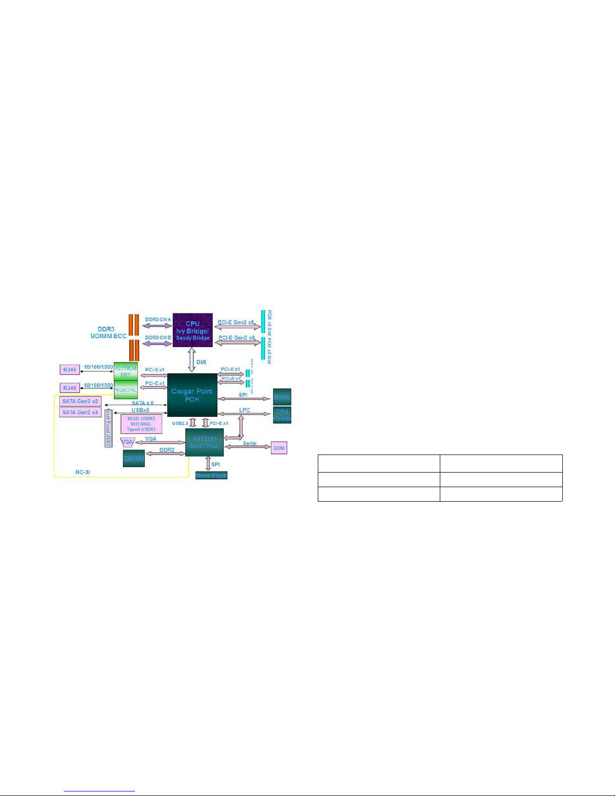
Functional Architecture
Functional Architecture
Processor
The S100-MB1W motherboard supports an Intel ® Xeon processor E3-1200 v2 family processor (codenamed Ivy Bridge) or
an Intel ® Xeon processor E3-1200 processor (codenamed
Sandy Bridge). See the socket location on mainbaord in Moth-
erboard Connectors and Jumpers.
Sandy Bridge
The Sandy Bridge processor comes in a FCLGA 1155 package,
and plugs into a H2 socket. There are two FMBs with the following power ratings.
The Sandy Bridge processor has an Integrated Memory Controller (IMC) that supports two channels of DDR3 memory and
two DPCs. The DDR3 I/O signal voltage is 1.5V.
Sandy Bridge Processor TDP
FMB TDP (W)
09B 95
09A 65
Page 27
ABOUT THE SERVER PROCESSOR
1-6
The Sandy Bridge H2 processor has two or four cores with 1.5
MB of L3 cache per core. One 16-lane or two 8-lane second
generation PCI Express interface is integrated into the processor. The processor and PCH are connected via a second generation DMI. Processor power consumption is shown in the
following table.
Early samples of the Sandy Bridge processor were labelled
QGBS, while later LGA1155 socket samples were correctly
labelled QLKB.
Ivy Bridge
The Ivy Bridge processor comes in a FCLGA 1155 package,
and plugs into a H2 socket. The Ivy Bridge processor has an
IMC that supports two channels of DDR3 memory and two
DPCs. The DDR3 I/O signal voltage is 1.5V. There is no support
for 1.35V DDR3L signalling.
The Ivy Bridge H2 processor has 2 or 4 cores with 2 MB of L3
cache per core. One 16-lane or two 8-lane third generation PCI
Express interface is integrated into the processor. The processor and PCH are connected via a second generation DMI. Processor power consumption is shown in the following table.
UDIMM Support
UDIMM support enables cost-optimized value platforms that
can support up to 8GB per core on the Bromolow platform.
Sandy Bridge Processor Power Consumption
CORES TDP
Quad 95W / 80W / ~45W (LV)
Dual 65W / ~20W (ULV)
Ivy Bridge Processor Power Consumption
CORES TDP
Quad 95W / 80W / ~20W (LV)
Dual 77W / ~17W (ULV)
Note:
Unsupported configurations may still boot
There is no support for RDIMMs or LV DIMMs
All channels in a system run at the highest common fre-
quency
Non-ECC UDIMMs are supported on workstation plat-
forms, but not on server platforms
Mixing ECC and non-ECC UDIMMs is not supported
Static CLTT is supported via the BMC, provided ECC
DIMMs have a thermal sensor
DDR3L DIMMs running at 1.5V are POR for use with IVB-
H2 DDR3L. DIMMs running at 1.35V are not supported.
Page 28

ABOUT THE SERVER PCI-EXPRESS
1-7
Maximum Memory Capacity
PCI-Express
The S100-MB1W motherboard supports two PCIe x8 G2/3 slots
via the processor and two PCIe x1 slots via the PCH. PCIe x8
slots have a riser board for 1U chassis. The Sandy Bridge processor supports G2 PCIe slots and the Ivy Bridge processor
supports G3 slots. PCI Express links are used as described in
the following table. See the connector locations on mainbaord
in Motherboard Connectors and Jumpers.
LPC Bus
The LPC bus is connected to the PCH, BMC and TPM.
Trusted Platform Module
TPM Module
The TPM controller on S100-MB1W motherboard is produced
by STMicroelectronics. The main source is
ST19NP18BR28PVIT and secondary is ST33ZP24AR28PVSH.
The S100-MB1W motherboard optionally supports TPM 1.2 via
the ST19NP18BR28PVIM.
Information on TPM connector pins, see TPM Pin-Outs Defini-
tion.
Bromolow Platform UDIMM Support
DIMM
S
LOTS/
C
HANNEL
DIMMS
PER
C
HANNEL
DIMM
T
YPE
POR
S
PEED
RANK PER
DIMM
S
UPPORT
ED
B
OARD
L
AYER
21
Unbuffered
DDR3
ECC
1066,
1333
SR, DR 4
22
Unbuffered
DDR3
ECC
1066,
1333
SR, DR 4
Maximum Memory Capacity
MAX MEMORY
P
OSSIBLE
1GB DRAM 2GB DRAM 4GB DRAM
Single Rank
UDIMM
4GB
4 x 1GB DIMMs
8GB
4 x 2GB DIMMs
16GB
4 x 4GB DIMMs
Dual Rank
UDIMM
8GB
4 x 2GB DIMMs
16GB
4 x 4GB DIMMs
32GB
4 x 8GB DIMMs
PCH PCIe link Utilization
PCIE DESTINATION TYPE OF PCIE LINK
AST2150 PCIe x1
WG82574L GbE PCIe x1
82579LM GbE PCIe x1
Page 29

ABOUT THE SERVER LAN ON MOTHERBOARD
1-8
LAN on Motherboard
The S100-MB1W has an on-board Intel 82579LM GbE (Lewisville) 10/100/1000Base-TX Ethernet interface, which is connected to the PCH via a single lane PCIe link, and 82579 only
runs at 1250 Mb/s speed, which is 1/2 of the PCIe Specification
v1.1.The S100-MB1W also has an integrated Intel
82574L(Hartwell) Gigabit Ethernet MAC and PHY functionality,
full duplex operation at 10/100/1000 Mb/s, and is capable of
sharing the interface with the AST2150 BMC. See the ports
location on mainbaord in Motherboard Connectors and Jump-
ers.
The NC-SI link supports both pass-through traffic between the
BMC AST2150 and the 82574 LAN functions that meet the latest NC-SI specification as it relates to the RMII electrical interface.
Video
The S100-MB1W motherboard has an AST2150 BMC that provides a VGA output at 1600 x 1200 resolution at 60Hz with 16bits per pixel color depth. See the connector location on mainbaord in Motherboard Connectors and Jumpers.
The AST2150 also provides system management functions via
the embedded 266MHz ARM 926EJ processor and 128 MB of
DDR2 memory.
The combined management and video functionality of the
AST2150 BMC chip deliver video redirection over IP networks.
This redirection uses YUV444/YUV420 video compression to
send 1600x1200x24-bit images at 60 frames per second. USB
can also be redirected over IP with the USB 2.0 virtual hub.
For information on video connector pin-outs, see Video Con-
nector PinOuts.
Serial Port
See the port location on mainbaord in Motherboard Connectors
and Jumpers.
For information on serial port connector pin-outs, see Serial
Port Pin-Outs.
Page 30

ABOUT THE SERVER FRONT PANEL
1-9
Front Panel
Front Panel LEDs
Front Panel LEDs
SYSTEM LED DISPLAY STATUS DESCRIPTION VOLTAGE OWNER
Rack-mounted/
To we r
Status LED
Blink
System Failure: Critical Fan, Temperature,
Memory Error, Process Hot, Critical IRQ…etc.
P5V_STBY BMC
Non-Critical Failure: Non- critical Fan, Voltage,
Temperature state, CPU Thermal Trip
OFF
SEL Cleared
Last pending warning or error has been deasserted
Rack-mounted ID LED
Blink Unit selected for identification
P3V3_STBY BMC
OFF No identification request
Rack-mounted/
Tower chassis
HDD LED
Blink
Hard Disk Drive Access (Only on board SATA
port)
P3V3 PCH
OFF No access (non-SAS)
Rack-mounted/
Tower chassis
Power Button+LED
ON System Power On
P3V3_STBY PCHOFF System Power Off
Blink System into sleep
Rack-mounted NIC1 Speed Blink LAN access (off when there is traffic) P3V3_STBY Lewisville 82579LM
Rack-mounted NIC2 Speed Blink LAN access (off when there is traffic) P3V3_STBY Hartwell 82574L
Page 31

ABOUT THE SERVER FRONT PANEL
1-10
Rear LAN LEDs
Onboard BMC Heartbeat LED
SYSTEM LED COLOR DISPLAY STATUS DESCRIPTION VOLTAGE OWNER
Rack-mounted ID LED Blue
Blink Unit selected for identification
P3V3_STBY BMC
OFF No identification request
Rack-mounted/
Tower chassis
NIC1
Link/Act
Green
ON LAN Link
P3V3_STBY
Lewisville
82579LM
Blink
LAN access (off when there is
traffic)
-- OFF Disconnect
Speed
Green ON
Green, link speed is 100Mbits/
sec
Amber ON
Amber, link speed is 1000Mbits/
sec
-- OFF OFF, link speed is 10Mbits/sec
Rack-mounted/
Tower chassis
NIC2
Link/Act
Green
ON LAN Link
P3V3_STBY Hartwell 82574L
Blink
LAN access (off when there is
traffic)
-- OFF Disconnect
Speed
Green ON
Green, link speed is 100Mbits/
sec
Amber ON
Amber, link speed is 1000Mbits/
sec
-- OFF OFF, link speed is 10Mbits/sec
Rack-mounted/
Tower chassis
BMC Heartbeat Green
Blink BMC is activity
P3V3_STBY BMC
Solid BMC is going to reset
Page 32

ABOUT THE SERVER CLOCKS
1-11
Clocks
The Bromolow PCH has an integrated clock generator.
System Fan Setup
Fan Setup for 1U and 2U Rack Chassis
For 1U rack chassis is suggested to use three (3) 40 x 28 or 40
x 56 system fans to cool down the motherboard. For more
details see the following table. For details on system fan zones,
see 1U and 2U Rack Chassis Fan Setup.
For 2U rack chassis is suggested to use three (3) 80 x 38 system fans to cool down the motherboard. For more details see
the following table. For details on system fan zones, see 1U
and 2U Rack Chassis Fan Setup.
1U and 2U Rack Chassis Fan Setup
1U and 2U Rack Chassis Fan Setup
FAN ZONE FAN CONNECTOR
1 4028/4056 fan
HDD_FAN (see Motherboard Con-
nectors and Jumpers)
2 4028/4056 fan (x2)
CPU_FAN+ SYS_FAN (Mother-
board Connectors and Jumpers)
2U Rack Chassis Fan Setup
FAN ZONE FAN CONNECTOR
1 8038 Fan
HDD_FAN (see Motherboard Connectors
and Jumpers)
2 8038 Fan (x2)
CPU_FAN+ SYS_FAN (Motherboard Con-
nectors and Jumpers)
FAN ZONE 2FAN ZONE 1
Rear
122
Page 33

ABOUT THE SERVER SYSTEM FAN SETUP
1-12
Fan Setup for Tower Chassis
To setup system fan for tower chassis, follow the table and illustration hereafter.
Tower Rack Chassis Fan Setup (tower chassis visible with-
out side door)
Tower Chassis Fan Setup
ITEM NO.FAN CONNECTOR
1 8038 fan
SYS_FAN (Motherboard Connec-
tors and Jumpers)
2
Heatsink with
active fan
CPU_FAN (Motherboard Connec-
tors and Jumpers)
1
2
Top
Bottom
Page 34

ABOUT THE SERVER OPERATING ENVIRONMENT
1-13
Operating Environment
Operating System Support
The supported operating systems are as follows:
Microsoft
®
Windows Server® 2008 R2 with SP1 Enter-
prise (64-bit, including Hyper-V)
Red Hat
®
Enterprise Linux® 6 Update 1 X86_64 (including
KVM)
Novell SUSE Linux Enterprise Server 11 SP2 x86_64
(including Xen)
Microsoft
®
Windows Server® 2008 X64, with SP2, Enter-
prise Edition
Microsoft
®
Windows Server® 2008 X86, with SP2, Enter-
prise Edition
Microsoft
®
Windows 7 _64 Bit
Red Hat
®
Enterprise Linux® 5 Update 7 X86_64 (including
KVM)
Novell SUSE Linux Enterprise Server 10 SP4 x86_64
Operating Environment Characteristics
CHARACTERISTIC CONDITION
Operating Temperature
10
° C ~ 35° C (50° F ~ 95° F)
Non-Operating Temperature
- 40
° C ~ 70° C (-40° F ~ 158° F)
In/Non-Operating Humidity
90%, non-condensing at 35
° C
(95
° F)
Page 35

Installing Hardware
Chapter 2
Page 36

INSTALLING HARDWARE SAFETY MEASURES
2-1
2.2. Safety Measures
WARNING!
Only perform troubleshooting as authorized by the product documentation, or as directed by a service and support team.
Repairs not authorized by warranty may void the warranty and
damage the system.
WARNING!
Always make sure to disconnect the system from the AC electrical source. Powering down the system DOES NOT ensure
there is no electrical activity in the system.
WARNING!
Server components and circuit boards are easily damaged by
discharges of static electricity. Working on servers that are connected to a power supply can be extremely dangerous. Follow
the guidelines below to avoid personal injury or damage to the
server.
WARNING!
Always disconnect the server from the power outlet whenever
you are working inside the server case.
WARNING!
Wear a grounded wrist strap. If none are available, discharge
any personal static electricity by touching the bare metal chassis of the server case, or the bare metal body of any other
grounded device.
!
!
!
!
!
WARNING!
Humid environments tend to have less static electricity than dry
environments. A grounding strap is warranted whenever danger
of static electricity exists.
WARNING!
Do not touch the components on the unless it is necessary to
do so. Do not flex or stress circuit boards.
WARNING!
Leave all replacement components inside their static-proof
packaging until you are ready to use them.
!
!
!
Page 37

INSTALLING HARDWARE PROCESSOR HEAT SINKS
2-2
2.3. Processor Heat Sinks
Removing a Processor Heat Sink
1. Loosen the captive screw(s) in the order shown.
Removing the Heat Sink
2. Remove the heat sink.
3. Repeat steps for the remaining heat sink.
Note:
All the instructions and images in this section are for illustration
purposes only and may not reflect the actual product.
WARNING!
The heatsink remains hot after the system has been powered
down. Allow sufficient time to cool before handling system components.
!
1
2
3
4
Page 38

INSTALLING HARDWARE INSTALLING A PROCESSOR HEAT SINK
2-3
Installing a Processor Heat Sink
1. Align the heat sink over the processor plate.
2. Install the heat sink. Make sure the screw(s) are inserted
into the screw wells.
Installing Heat Sink
3. Tighten the screw(s) in the order shown.
Tightening Screws
4. Repeat steps for the remaining heat sink.
1
2
3
4
Page 39

INSTALLING HARDWARE ACTIVE FAN PROCESSOR HEAT SINK
2-4
2.4. Active Fan Processor Heat Sink
Removing an Active Fan Processor Heat Sink
1. Disconnect the active fan heat sink cable from the motherboard connector. See Motherboard Jumpers.
2. Release the active fan heat sink fastener, as instructed in
the following:
a) Turn the fastener to unlock.
b) Gently pull up on the fastener to release. Remove the
diagonally positioned fastener to prevent undue stress on
the remaining fasteners.
Releasing Fasteners
Note:
All the instructions and images in this section are for illustration
purposes only and may not reflect the real product.
WARNING!
The processor remains hot after the system has been powered
down. Allow sufficient time to cool before handling system components.
!
b
a
Page 40

INSTALLING HARDWARE INSTALLING A PROCESSOR
2-5
3. Remove the active fan heat sink.
Removing Active Fan Heat Sink
Installing a Processor
Prerequisite:
Install the processor. See Installing a Processor.
Apply an approved thermal grease on the center of the
processor.
1. Place active fan heat sink on processor.
Installing Active Fan Heat Sink
Page 41

INSTALLING HARDWARE INSTALLING A PROCESSOR
2-6
2. Secure the active fan heat sink with the fastener(s). Do as
follows:
a) Gently push the pairs of the diagonal fastener(s) until
click in place.
b) Lock the fasteners.
Locking Fasteners
3. Connect active fan heat sink cable to the connector on
mainboard. See Motherboard Jumpers.
a
b
Page 42

INSTALLING HARDWARE PROCESSORS
2-7
2.5. Processors
Removing a Processor
1. Pull the locking lever of the processor socket out and up
as shown.
Release Locking Lever
2. Lift the processor load plate (A).
Lifting Processor Load Plate
Note:
All the instructions and images in this section are for illustration
purposes only and may not reflect the real product.
WARNING!
The processor remains hot after the system has been powered
down. Allow sufficient time to cool before handling system components.
!
A
Page 43

INSTALLING HARDWARE INSTALLING A PROCESSOR
2-8
3. Remove the processor.
Removing Processor
Installing a Processor
1. Pull the locking lever of the processor socket out and up
as shown.
Release Locking Lever
Page 44

INSTALLING HARDWARE INSTALLING A PROCESSOR
2-9
2. Lift the processor load plate (A).
Opening Load Plate
3. Remove the processor dust cover.
4. .Locate the pin-1 (A) on processor and the pin-1 (B) corner of the socket.
5. Locate the indents (C) on processor and corresponding
tab (D) on socket.
6. Install the processor.
Installing Processor
7. Replace the processor load plate and locking lever to lock
the processor in place.
Locking Processor
8. Repeat steps for the second processor.
A
Note:
Use the socket cover to protect the socket when the socket is
empty.
A
B
C
D
Page 45

INSTALLING HARDWARE MEMORY MODULES
2-10
2.6. Memory Modules
General Guidelines
See Motherboard Connectors and Jumpers to locate the memory slots on motherboard.
Memory Population Rules
The system memory frequency is always the lowest frequency
of all installed memory modules. The frequencies of installed
memory modules is determined via their the SPD registers.
The system memory controller supports one or two DIMMs per
channel. A DIMM must be installed in both channels for dualchannel modes. One or two DIMMs can be installed for singlechannel mode.
Removing a Memory Module
Note:
All the instructions and images in this section are for illustration
purposes only and may not reflect the real product.
Note:
DIMM1 must be installed in all configurations.
DIMM1 is identified by the CS#[3:2], OyDT[3:2], and CKE[3:2]
signals.
Note:
For more details, refer to RS - Desktop and UP Server/Workstation Sandy Bridge Processors External Design Specification Volume 1.
CAUTION!
HANDLE THE MEMORY MODULE BY THE EDGES AT ALL TIMES.
WARNING!
Memory modules remain hot after the system is powered down.
Allow sufficient time for the memory modules to cool before
handling system components.
!
!
Page 46

INSTALLING HARDWARE INSTALLING A MEMORY MODULE
2-11
1. Press down on the two memory module slot levers (A).
The memory module partially ejects.
Removing Memory Module
2. Lift out the memory module.
Installing a Memory Module
Push the memory module firmly into the memory module slot.
The locking latches should automatically close over the edges
of the memory board when fully inserted into the slot.
Installing Memory Module
A
1
2
1
CAUTION!
HANDLE THE MEMORY MODULE BY THE EDGES AT ALL TIMES.
!
Page 47

INSTALLING HARDWARE MOTHERBOARD
2-12
2.7. Motherboard
General Guidelines
All motherboards have standard mounting holes to fit different
types of chassis. The chassis may have both plastic and metal
mounting fasteners. However, it is highly recommended to use
metal mounting fasteners because they ground the motherboard to the chassis.
Removing a Motherboard
1. Remove the screw(s) securing the motherboard to the
chassis.
2. Remove the standoff(s) from the chassis.
Removing Motherboard
Note:
All the instructions and images in this section are for illustration
purposes only and may not reflect the actual product.
CAUTION!
TO PREVENT DAMAGE, PRIOR INSTALLING A MOTHERBOARD, MAKE
SURE THE MOUNTING HOLES OF THE BOARD AND CHASSIS MATCH.
CAUTION!
TO PREVENT DAMAGE TO THE MOTHERBOARD AND ITS COMPO-
NENTS, DO NOT USE FORCE GREATER THAN 5 LB/INCH ON EACH
MOUNTING SCREW DURING MOTHERBOARD INSTALLATION.
CAUTION!
SOME COMPONENTS ARE VERY CLOSE TO THE MOUNTING HOLES.
M
AKE CAUTION TO AVOID DAMAGING THESE COMPONENTS WHEN
INSTALLING THE MOTHERBOARD TO THE CHASSIS.
!
!
!
1
2
Page 48

INSTALLING HARDWARE INSTALLING A MOTHERBOARD
2-13
Installing a Motherboard
1. Install the standoff(s) to the chassis.
2. Align the motherboard mounting holes with the standoff(s).
3. Install the motherboard.
4. Install the screw(s) to the motherboard.
Installing Motherboard
1
4
Page 49

BIOS
Chapter 3
Page 50

BIOS BIOS UPDATE UTILITY
3-1
3.1. BIOS Update Utility
The flash ROM contains system initialization routines, the BIOS
Setup Utility, and runtime support routines. The exact layout is
subject to change, as determined by BIOS. The flash ROM also
contains initialization code in compressed form for onboard
peripherals, like SCSI, NIC and video controllers. The complete
ROM is visible, starting at physical address 4 GB minus the size
of the flash ROM device.
A 16-KB parameter block in the flash ROM is dedicated to storing configuration data that controls the system configuration
(ESCD). Application software must use standard APIs to
access these areas; application software cannot access the
data directly.
BIOS Update Utility
Server platforms support DOS-based, Windows-based, and
Linux-based firmware update utilities. This utility loads a fresh
copy of the BIOS into the flash ROM.
The BIOS update may affect the following items:
The system BIOS, including the recovery code, setup util-
ity and strings.
Onboard video BIOS, RAID BIOS, and other option
ROMS for the devices embedded on the server board.
Memory reference code.
Microcode updates.
Recovery Mode
Recovery process can be initiated by setting the recovery
jumper. BIOS would detect the recovery jumper set and start to
execute recovery code.
The BIOS consists of three parts, the Main BIOS Section, the
NVRAM Section, and the Boot Block Recovery Section. The
Main BIOS Section and the NVRAM Section will be updated
during recovery process, but the Boot Block will be preserved.
BIOS recovery could be held through a USB removable drive,
and the recovery media must include the BIOS image file,
S1W_REC.ROM.
Page 51

BIOS RECOVERY MODE
3-2
Recovery Flow
The BIOS has an embedded recovery technique in the 'boot
block'. In the event that the BIOS becomes corrupt, the boot
block can be used to restore the BIOS to a working state. The
routine is called when the 'system block' of the BIOS is empty or
corrupt. The restore routine when called will access the USB
drive looking for a file named S1W_REC.ROM. This is the reason the USB drive light comes on and the drive appears to be in
use. If the file (S1W_REC.ROM) is found it is loaded into the
'system block' of the BIOS to replace the corrupted information
To restore your BIOS copy the most recent version of your
motherboards BIOS file to a USB key and rename it
S1W_REC.ROM
The recovery mode procedure is as follows:
1. Rename the good known BIOS as S1W_REC.ROM.
2. Plug in a removable USB disk.
3. Save the S1W_REC.ROM. file into the removable USB
disk.
4. Short the BIOS recovery jumper. See Motherboard Con-
nectors and Jumpers.
5. Power on the server.
The system will automatically enter BIOS Setup menu and display a Recovery page as follows:
BIOS Recovery Menu
The recovery process begins.
6. Set the BIOS recovery jumper back to default position
and wait until the recovery process is completed. See
Version 2.10.1208 - Copyright (C) 2010 American Megatrends, Inc.
Aptio Setup Utility - Copyright (C) 2010 American Megatrends, Inc.
Main Advanced Chipset Server Mgmt RecoveryBoot Security Save & Exit
WARNING! BIOS Recovery mode has been detected
Proceed with flash update
Set this option to
reset NVRAM to
default values
: Select Screen
: Select Item
Enter: Select
+/-: Change Opt.
F1: Genenal Help
F8: Previous Values
F9: Optimized Defaults
F10: Save & Exit
ESC: Exit
Page 52

BIOS CLEAR CMOS
3-3
Motherboard Connectors and Jumpers and the following
figure.
BIOS Recovery Completed
Reboot the system with the new BIOS.
Clear CMOS
The following steps will load the BIOS defaults by jumber:
1. Power down the system.
2. Move CMOS clear jumper from pins 1-2 to pins 2-3 for a
few seconds. See Motherboard Connectors and Jumpers.
3. Move CMOS clear jumper back to pins 1-2. See Mother-
board Connectors and Jumpers.
4. System automatically powers on.
5. Check BIOS defaults are loaded.
Clear Password
1. Power down the system.
2. Move password clear jumper from pins 1-2 to pins 2-3.
See Motherboard Connectors and Jumpers.
3. Power on the system.
4. Make sure password is cleared.
5. Power down the system.
6. Move password clear jumper from pins 2-3 back to pins 1-
2. See Motherboard Connectors and Jumpers.
7. Power on the system.
8. Set new password.
Version 2.10.1208 - Copyright (C) 2010 American Megatrends, Inc.
Aptio Setup Utility - Copyright (C) 2010 American Megatrends, Inc.
Main Advanced Chipset Server Mgmt RecoveryBoot Security Save & Exit
WARNING! System firmware is being updated.
Keyboard is locked.
DO NOT TURN THE POWER OFF !!!
Once firmware update is completed
press any key to reboot the system
Flash update progress completed.
: Select Screen
: Select Item
Enter: Select
+/-: Change Opt.
F1: Genenal Help
F8: Previous Values
F9: Optimized Defaults
F10: Save & Exit
ESC: Exit
Page 53

BIOS BIOS SETUP UTILITY
3-4
3.2. BIOS Setup Utility
The BIOS Setup utility is provided to perform system configuration changes and to display current settings and environment
information.
The BIOS Setup utility stores configuration settings in system
non-volatile storage. Changes affected by BIOS Setup will not
take effect until the system is rebooted. The BIOS Setup Utility
can be accessed during POST by using the <DEL> or <F2>
key.
The following sections describe the look and behavior for platform Setup.
Operation
BIOS Setup has the following features:
The server board BIOS will only be available in English.
BIOS Setup is functional via console redirection over vari-
ous terminal emulation standards. This may limit some
functionality for compatibility, e.g., usage of colors, some
keys or key sequences, or support of pointing devices.
Setup Page Layout
The setup page layout is sectioned into functional areas. Each
occupies a specific area of the screen and has dedicated functionality. The following table lists and describes each functional
area.
BIOS Setup Page Layout
FUNCTIONAL
A
REA
DESCRIPTION
Title Bar
The title bar is located at the top of the screen and displays the title of the form (page) the user is currently
viewing. It may also display navigational information.
Setup Item List
The Setup Item List is a set of controllable and informational items. Each item in the list occupies the left
column of the screen.
A Setup Item may also open a new window with more
options for that functionality on the board.
Item Specific
Help Area
The Item Specific Help area is located on the right side
of the screen and contains help text for the highlighted
Setup Item. Help information may include the meaning
and usage of the item, allowable values, effects of the
options, etc.
Page 54

BIOS ENTERING BIOS SETUP
3-5
Entering BIOS Setup
BIOS Setup is started by pressing <F2> during boot time when
the OEM logo is displayed.
When Quiet Boot is disabled, there will be a message “press
<F2> to enter setup” displayed on the diagnostics screen.
Serious errors will cause the system to enter setup, opening
with the error manager screen.
Keyboard Commands
The bottom right portion of the Setup screen provides a list of
commands that are used to navigate through the Setup utility.
These commands are displayed at all times.
Each Setup menu page contains a number of features. Except
those used for informative purposes, each feature is associated
with a value field. This field contains user-selectable parameters. Depending on the security option chosen and in effect by
the password, a menu feature's value may or may not be
changeable. If a value is non-changeable, the feature's value
field is inaccessible and displays as "grayed out."
Keyboard Command Bar
The Keyboard Command Bar is located at the bottom
right of the screen and continuously displays help for
keyboard special keys and navigation keys.
BIOS Setup Page Layout (Continued)
FUNCTIONAL
A
REA
DESCRIPTION
Keyboard Commands
Key OPTION DESCRIPTION
<Enter>
Execute
Command
The <Enter> key is used to activate sub-menus
when the selected feature is a sub-menu, or to
display a pick list if a selected option has a value
field, or to select a sub-field for multi-valued features like time and date. If a pick list is displayed, the <Enter> key will select the currently
highlighted item, undo the pick list, and return
the focus to the parent menu.
Page 55

BIOS KEYBOARD COMMANDS
3-6
<Esc> Exit
The <Esc> key provides a mechanism for backing out of any field. When the <Esc> key is
pressed while editing any field or selecting features of a menu, the parent menu is re-entered.
When the <Esc> key is pressed in any submenu, the parent menu is re-entered. When the
<Esc> key is pressed in any major menu, the
exit confirmation window is displayed and the
user is asked whether changes can be discarded. If No is selected and the <Enter> key is
pressed, or if the <Esc> key is pressed, the
user is returned to where he/she was before
<Esc> was pressed, without affecting any existing any settings. If Yes is selected and the
<Enter> key is pressed, setup is exited and the
BIOS returns to the main System Options Menu
screen.
↑
Select
Item
The up arrow is used to select the previous
value in a pick list, or the previous option in a
menu item's option list. The selected item must
then be activated by pressing the <Enter> key.
↓
Select
Item
The down arrow is used to select the next value
in a menu item's option list, or a value field's
pick list. The selected item must then be activated by pressing the <Enter> key.
↔
Select
Menu
The left and right arrow keys are used to move
between the major menu pages. The keys have
no affect if a sub-menu or pick list is displayed.
Keyboard Commands (Continued)
Key OPTION DESCRIPTION
<Tab>
Select
Field
The <Tab> key is used to move between fields.
For example, <Tab> can be used to move from
hours to minutes in the time item in the main
menu.
-
Change
Val ue
The minus key on the keypad is used to change
the value of the current item to the previous
value. This key scrolls through the values in the
associated pick list without displaying the full
list.
+
Change
Val ue
The plus key on the keypad is used to change
the value of the current menu item to the next
value. This key scrolls through the values in the
associated pick list without displaying the full
list. On 106-key Japanese keyboards, the plus
key has a different scan code than the plus key
on the other keyboard, but will have the same
effect.
<F9>
Setup
Defaults
Pressing <F9> causes the following to appear:
\
If Yes is highlighted and <Enter> is pressed, all
Setup fields are set to their default values. If No
is highlighted and <Enter> is pressed, or if the
<Esc> key is pressed, the user is returned to
where they were before <F9> was pressed without affecting any existing field values.
Keyboard Commands (Continued)
Key OPTION DESCRIPTION
Load Optimized Defaults?
Yes N o
Page 56

BIOS MENU SELECTION BAR
3-7
Menu Selection Bar
The Menu Selection Bar is located at the top of the BIOS Setup
Utility screen. It displays the major menu selections available to
the user. By using the left and right arrow keys, the user can
select the menus listed here.
Server Platform Setup Utility
Screens
The sections below describe the screens available for the configuration of a server platform. In these sections, tables are
used to describe the contents of each screen. These tables follow the following guidelines:
The text and values in the Setup Item, Options, and Help
columns in the tables are displayed on the BIOS Setup
screens.
Bold text in the Options column of the tables indicates
default values. These values are not displayed in bold on
the setup screen. The bold text in this document is to
serve as a reference point.
The Comments column provides additional information
where it may be helpful. This information does not appear
in the BIOS Setup screens.
Information in the screen shots that is enclosed in brack-
ets (< >) indicates text that varies, depending on the
option(s) installed. For example <Current Date> is
replaced by the actual current date.
Information that is enclosed in square brackets ([]) in the
tables indicates areas where the user needs to type in text
instead of selecting from a provided option.
Whenever information is changed (except Date and Time)
the systems requires a save and reboot to take place.
<F10>
Save and
Exit
Pressing <F10> causes the following message
to appear:
If Yes is highlighted and <Enter> is pressed, all
changes are saved and Setup is exited. If No is
highlighted and <Enter> is pressed, or the
<Esc> key is pressed, the user is returned to
where they were before <F10> was pressed
without affecting any existing values.
Keyboard Commands (Continued)
Key OPTION DESCRIPTION
Save configuration and exit?
Yes N o
Page 57

BIOS MAIN SCREEN
3-8
Pressing <ESC> will discard the changes and boot the
system according to the boot order set from the last boot.
Main Screen
The Main screen is the screen that is first displayed when BIOS
Setup is entered, unless an error has occurred. If an error has
occurred, the Error Manager screen will be displayed instead.
Main Screen
Main Advanced Chipset Server Mgmt Event LogsBoot Security Save & Exit
Set the Date, Use Tab to
switch between data elements.
: Select Screen
: Select Item
Enter: Select
+/-: Change Opt.
F1: Genenal Help
F8: Previous Values
F9: Optimized Defaults
F10: Save & Exit
ESC: Exit
BIOS Information
BIOS Vendor
Core Version
Compliancy
Project Version
Build Date
Memory Information
Total Memory
System Date
System Time
Access Level
American Megatrends
4.6.4.0
UEFI 2.1
S1W_2A02.01
12/07/2010
2048 MB (DDR3 1333)
[Tue 12/07/2010]
[16:39:38]
Administrator
Main Screen Fields
SETUP ITEM OPTIONS
HELP
T
EXT
COMMENTS
BIOS Vendor
Information only. Displays the
BIOS Vendor.
Core Version
Information only. Displays the
AMI BIOS Core version.
Compliancy
Information only. Displays the
BIOS compliancy.
Project Version
Information only. Displays the
Project version.
Build Date
Information only. Displays the
BIOS build date.
Total Memory
Information only. Displays the
Total System Memory Size.
System
Data
[Day of
week
MM/DD/
YYYY]
Set the
Date.
Use Tab
to switch
between
Date elements.
System
Time
[HH:MM:
SS]
Set the
Time .
Use Tab
to switch
between
Time elements.
Page 58

BIOS ADVANCED SCREEN
3-9
Advanced Screen
The Advanced screen provides an access point to configure
several options. On this screen, the user selects the option that
is to be configured. Configurations are performed on the
selected screen, not directly on Advanced screen.
To access this screen from Main screen, press the right arrow
until Advanced screen is chosen.
Advanced Screen
Access
Level
Information only. Displays the
Access Level.
Main Screen Fields (Continued)
SETUP ITEM OPTIONS
HELP
T
EXT
COMMENTS
Main Advanced Chipset Server Mgmt Event LogsBoot Security Save & Exit
: Select Screen
: Select Item
Enter: Select
+/-: Change Opt.
F1: Genenal Help
F8: Previous Values
F9: Optimized Defaults
F10: Save & Exit
ESC: Exit
Runtime Error Logging
Onboard Device Settings
PCI Subsystem Settings
Trusted Computing
WHEA Configuration
CPU Configuration
SATA Configuration
Intel TXT(LT) Configuration
USB Configuration
Super IO Configuration
Serial Port Console Redirection
CPU PPM Configuration
Runtime Error Logging Support
Setup Option.
Page 59

BIOS ADVANCED SCREEN
3-10
Advanced Screen
SETUP ITEM OPTIONS HELP TEXT COMMENTS
Runtime
Error Logging
Runtime Error Logging Support Setup
Option
Onboard
Device Configuration
Onboard Device
Parameters
PCI Subsystem Settings
PCI, PCI-X and PCI
Express Settings
Trusted Computing
Trusted Computing
Settings.
WHEA Configuration
General WHEA
Configuration settings.
CPU Configuration
CPU Configuration
Parameters.
SATA Configuration
SATA Devices Configuration
Intel TXT(LT)
Configuration
Intel Trusted Execution Technology
Configuration
USB Configuration
USB Configuration
Parameters.
Super IO
Configuration
System Super IO
Chip Parameters
Serial Port
Console
Redirection
Serial Port Console
Redirection
CPU PPM
Configuration
CPU PPM Configuration Parameters
Advanced Screen (Continued)
SETUP ITEM OPTIONS HELP TEXT COMMENTS
Page 60

BIOS ADVANCED SCREEN
3-11
PCI Screen
The PCI Screen provides fields to configure PCI add-in cards,
the onboard NIC controllers, and video options. To access this
screen from the Main screen, select Advanced | PCI.
PCI Subsystem Settings Screen
PCI Subsystem Settings Screen
SETUP ITEM OPTIONS HELP TEXT COMMENTS
PCI ROM
Priority
[EFI Compati-
ble ROM]
Main Advanced Chipset Server Mgmt Event LogsBoot Security Save & Exit
: Select Screen
: Select Item
Enter: Select
+/-: Change Opt.
F1: Genenal Help
F8: Previous Values
F9: Optimized Defaults
F10: Save & Exit
ESC: Exit
PCI Bus Driver Version
PCI ROM Priority
PCI Express Device Settings
Maximum Payload
ASPM Support
WARNING: Enablivg ASPM may cause some
PCI-E devices to fail
V 2.03.00
[EFI Compatible ROM]
[Auto]
[Disabled]
In czse of multiple Option
ROMs (Legacy and EFI
Compatible), specifies what
PCI Option ROM to launch.
Maximum
Payload
[Auto]
[128 Bytes]
[256 Bytes]
[512 Bytes]
[1024 Bytes]
[2048 Bytes]
[4096 Bytes]
Set Maximum
Payload of PCI
Express Device or
allow System
BIOS to select the
value.
ASPM Support
[Disabled]
[Auto]
[Force L0s]
Set the ASPM
Level: Force L0s Force all links to
L0s State : AUTO
- BIOS auto configure : DISABLE Disables ASPM
PCI Subsystem Settings Screen (Continued)
SETUP ITEM OPTIONS HELP TEXT COMMENTS
Page 61

BIOS ADVANCED SCREEN
3-12
TPM Screen
Trusted Computing Screen
WHEA Support Screen
WHEA Support Screen
Trusted Computing Fields
SETUP ITEM OPTIONS HELP TEXT COMMENTS
TPM SUPPORT
[Disabled]
[Enabled]
Main Advanced Chipset Server Mgmt Event LogsBoot Security Save & Exit
: Select Screen
: Select Item
Enter: Select
+/-: Change Opt.
F1: Genenal Help
F8: Previous Values
F9: Optimized Defaults
F10: Save & Exit
ESC: Exit
TPM Configuration
TPM SUPPORT
Current TPM Status Informatiom
TPM SUPPORT OFF
[Disable]
Enables or Disables TPM
support. O.S. will not show
TPM. Reset of platform is
required.
Main Advanced Chipset Server Mgmt Event LogsBoot Security Save & Exit
: Select Screen
: Select Item
Enter: Select
+/-: Change Opt.
F1: Genenal Help
F8: Previous Values
F9: Optimized Defaults
F10: Save & Exit
ESC: Exit
WHEA Support [Enabled] Enable or disable Windows
Hardware Error Architecture.
Page 62

BIOS ADVANCED SCREEN
3-13
Processor Configuration Screen
The Processor screen provides a place for the user to view the
processor core frequency, system bus frequency, and enable or
disable several processor options. The user can also select an
option to view information about a specific processor.
To access this screen from the Main screen, select Advanced |
Processor.
Processor Configuration Screen
WHEA Support Fields
SETUP ITEM OPTIONS HELP TEXT COMMENTS
WHEA Support
[Disabled]
[Enabled]
Enable or disable Windows Hardware Error
Architecture. When
Enabled the BIOS would
publishes WHEA-specific ACPI tables that
describe the platform
error interfaces for the
OS as Spec, and also
implements the ASL code
to support and enable
WHEA capability in the
platform.
Main Advanced Chipset Server Mgmt Event LogsBoot Security Save & Exit
: Select Screen
: Select Item
Enter: Select
+/-: Change Opt.
F1: Genenal Help
F8: Previous Values
F9: Optimized Defaults
F10: Save & Exit
ESC: Exit
Enabled for Windows XP and
Linux (OS optimized for
Hyper-Threading Technology)
and Disabled for other OS (OS
not optimized for
Hyper-Threading Technology).
When Disabled only one thread
per enabled core is enabled.
CPU Configuration
Intel(R) Xeon(R) CPU E31260L @ 2.40GHz
Processor Stepping
Microcode Revision
Max Processor Speed
Min Processor Speed
Processor Speed
Processor Cores
Intel HT Technology
Intel VT-x Technology
Intel SMX Technology
64-bit
L1 Data Cache
L1 Code Cache
L2 Cache
L3 Cache
Hyper-threading
Active Processor Cores
Execute Disable Bit
Intel Virtualization Technology
Hardware Prefetcher
Adjacent Cache Line Prefetch
206a7
6
2400 MHz
1600 MHz
2400 MHz
4
Supported
Supported
Supported
Supported
32 KB x 4
32 KB x 4
256 KB x 4
8192 KB
[Enabled]
[All]
[Enabled]
[Enabled]
[Enabled]
[Enabled]
Page 63

BIOS ADVANCED SCREEN
3-14
Processor Configuration Fields
SETUP ITEM OPTIONS HELP TEXT COMMENTS
CPU Type
Information only.
Displays the type
of the processor.
CPU Signature
Information only.
Displays the signature of the processor.
Microcode
Ptach
Information only.
Displays the microcode patch of the
processor.
Max CPU
Speed
Information only.
Displays maximum speed of the
processor.
Min CPU
Speed
Information only.
Displays the minimum speed of the
processor.
CPU Speed
Information only.
Displays the current speed of the
processor.
Processor
Cores
Information only.
Displays the cores
of the processor.
Intel HT
Technology
Information only.
Displays Intel HT
Technology supported or not.
Intel VT-x
Technology
Information only.
Displays Intel VT-x
Technology supported or not.
Intel SMX
Technology
Information only.
Displays Intel SMX
Technology supported or not.
64-bit
Information only.
Displays 64-bit
supported or not.
L1 Data
Cache
Information only.
Displays the L1
Data Cache Size.
L1 Code
Cache
Information only.
Displays L1 Code
Cache Size.
L2 Cache
Information only.
Displays the L2
Cache size.
L3 Cache
Information only.
Displays the L3
Cache size.
Processor Configuration Fields (Continued)
SETUP ITEM OPTIONS HELP TEXT COMMENTS
Page 64

BIOS ADVANCED SCREEN
3-15
Hyperthreading
[Disabled]
[Enabled]
Enabled for Windows XP and Linux
(OS optimized for
Hyper- Threading
Technology) and
Disabled for other
OS (OS not optimized for HyperThreading Technology). When Disabled only one
thread per enabled
core is enabled.
Active Processor Cores
[All] [1] [2]
[3]
Number of cores to
enable in each processor package.
For 4-cores processor displays All,
1, 2, or 3.
Execute Disable Bit
[Disabled]
[Enabled]
XD can prevent
certain classes of
malicious buffer
overflow attacks
when combined
with a supporting
OS (Windows
Server 2003 SP1,
Windows XP SP2,
SuSE Linux 9.2,
RedHat Enterprise
3 Update 3.)
Processor Configuration Fields (Continued)
SETUP ITEM OPTIONS HELP TEXT COMMENTS
Intel Virtualization Technology
[Disabled]
[Enabled]
When enabled, a
VMM can utilize the
additional hardware
capabilities provided by Vanderpool Technology
Hardware
Prefetcher
[Disabled]
[Enabled]
To turn on/off Mid
Level Cache (L2)
streamer
prefetcher.
Adjent
Cache Line
Prefetcher
[Disabled]
[Enabled]
To turn on/off
prefetching of adjacent cache lines.
Processor Configuration Fields (Continued)
SETUP ITEM OPTIONS HELP TEXT COMMENTS
Page 65

BIOS ADVANCED SCREEN
3-16
Intel TXT(LT) Screen
Intel TXT(LT ) Configuration Screen
USB Configuration Screen
The USB Configuration screen provides fields to configure the
USB controller options.
To access this screen from the Main screen, select Advanced |
USB Configuration.
USB Configuration Screen
Intel TXT(LT) Configuration Fields
SETUP ITEM OPTIONS HELP TEXT COMMENTS
Secure Mode
Extensons
(SMX)
[Disable]
[Enable]
Intel TXT(LT)
Support
[Disable]
[Enable]
Main Advanced Chipset Server Mgmt Event LogsBoot Security Save & Exit
: Select Screen
: Select Item
Enter: Select
+/-: Change Opt.
F1: Genenal Help
F8: Previous Values
F9: Optimized Defaults
F10: Save & Exit
ESC: Exit
Intel Trusted Execution Technology Configuration
Intel TXT support only can be enabled/disabled if SMX
is enabled. VT and VT-d support must also be enabled
prior to TXT.
Secure Mode Extensons (SMX)
Intel TXT(LT) Support
Enabled
[Disabled]
Main Advanced Chipset Server Mgmt Event LogsBoot Security Save & Exit
: Select Screen
: Select Item
Enter: Select
+/-: Change Opt.
F1: Genenal Help
F8: Previous Values
F9: Optimized Defaults
F10: Save & Exit
ESC: Exit
USB Configuration
USB Devices:
4 Drives, 2 Keyboard, 3 Mice, 5 Hubs
Legacy USB Support
Mass Storage Devices:
AMI Virtual Floppy 1.00
AMI Virtual HardDisk 1.00
SanDisk uSSD 5000 0.1
[Enabled]
[Auto]
[Auto]
[Auto]
[Auto]
Enables Legacy USB support.
AUTO option disables legacy
support if no USB devices are
connected. DISABLE option will
keep USB devices available
only for EFI applications.
Page 66

BIOS ADVANCED SCREEN
3-17
USB Configuration Fields
SETUP ITEM OPTIONS HELP TEXT COMMENTS
USB
Devices:
Information only. Display all of the USB
devices attached.
Legacy
USB Support
[Enabled]
[Disabled]
[Auto]
Enables Legacy
USB support.
AUTO option disables legacy support if no USB
devices are connected, DISABLE
option will keep
USB devices available only for EFI
applications.
Mass Storage
Devices:
[Auto]
Mass storage
device emulation
type. 'AUTO' enumerates devices
according to their
media format. Optical drives are emulated as 'CDROM',
drives with no
media will be emulated according to
a drive type.
Information only. Display only when the
type of the USB
devices attached.
AMI Virtual
CDROM
1.00
[Auto]
AMI Virtual
Floopy
1.00
[Auto]
AMI Virtual
HardDisk
1.00
[Auto]
SanDisk
uSSD 500
0.1
[Auto]
USB Configuration Fields (Continued)
SETUP ITEM OPTIONS HELP TEXT COMMENTS
Page 67

BIOS ADVANCED SCREEN
3-18
SATA Controller Screen
The SATA Controller screen provides fields to configure SATA
hard disk drives. It also provides information on the hard disk
drives that are installed.
SATA Controller Configuration Screen
Main Advanced Chipset Server Mgmt Event LogsBoot Security Save & Exit
: Select Screen
: Select Item
Enter: Select
+/-: Change Opt.
F1: Genenal Help
F8: Previous Values
F9: Optimized Defaults
F10: Save & Exit
ESC: Exit
SATA Mode
SATA port 0 / SSI HDD
SATA port 1 / SSI HDD
SATA port 2 / HDD0
SATA port 3 / HDD1
SATA port 4 / HDD2
SATA port 5 / HDD3
[AHCI]
Not Present
Not Present
Not Present
Not Present
Not Present
Not Present
Disabled/AHCI/RAID.
SATA Controller Configuration Fields
SETUP ITEM OPTIONS HELP TEXT COMMENTS
SATA Mode
[Disabled]
[AHCI]
[RAID]
Disabled/
AHCI/RAID
Select SATA Type
for onboard SATA
ports.
SATA Port0 / SSI
HDD0
Information only.
Displays the device
on Port0.
SATA Port1 / SSI
HDD1
Information only.
Displays the device
on Port1.
SATA Port2 /
HDD0
Information only.
Displays the device
on Port2.
SATA Por3 /
HDD1
Information only.
Displays the device
on Port3.
SATA Port4 /
HDD2
Information only.
Displays the device
on Port4.
SATA Por5 /
HDD3
Information only.
Displays the device
on Port5.
Page 68

BIOS ADVANCED SCREEN
3-19
Super I/O Configuration Screen
The Serial Ports screen provides fields to configure the Serial 0
[COM 1] and Serial 1 [COM2]..
To access this screen from the Main screen, select Advanced |
Super IO Configuration.
Super I/O Configuration Screen
Main Advanced Chipset Server Mgmt Event LogsBoot Security Save & Exit
: Select Screen
: Select Item
Enter: Select
+/-: Change Opt.
F1: Genenal Help
F8: Previous Values
F9: Optimized Defaults
F10: Save & Exit
ESC: Exit
Super IO Configuration
Super IO Chip
Serial Port 0 Configuration
Serial Port 1 Configuration
AST2150
Set Parameters of Serial Port
0 (COMA)
Super I/O Configuration Fields
SETUP ITEM OPTIONS HELP TEXT COMMENTS
Super IO
Chip
Information only.
Display Super IO
Chip.
Serial Port 0
Configuration
Set Parameters of
Serial Port 0.
Serial Port 1
Configuration
Set Parameters of
Serial Port 1.
Page 69

BIOS ADVANCED SCREEN
3-20
Onboard Device Configuration Screen
s
Onboard Device Configuration Screen
Onboard Device Configuration Fields
SETUP ITEM OPTIONS HELP TEXT COMMENTS
Onboard
LAN port 1
[Disabled]
[Enabled
With PXE]
[Enabled]
Disable/Enable
Onboard LAN port
1, w/, w/o including its PXE/iSCSI
boot-ROM.
Main Advanced Chipset Server Mgmt Event LogsBoot Security Save & Exit
: Select Screen
: Select Item
Enter: Select
+/-: Change Opt.
F1: Genenal Help
F8: Previous Values
F9: Optimized Defaults
F10: Save & Exit
ESC: Exit
Onboard Device Configuration
Onboard LAN port 1
Onboard LAN port 2
Port 1 MAC Address
Port 2 MAC Address
[Enabled With PXE]
[Enabled With PXE]
88:88:88:88:87:88
04:7d:7b:fe:6b:f9
Disable/Enable Onboard LAN
port 1, w/, w/o including its
PXE/iSCSI boot-ROM
Onboard
LAN port 2
[Disabled]
[Enabled
With PXE]
[Enabled]
Disable/Enable
Onboard LAN port
2, w/, w/o including its PXE/iSCSI
boot-ROM.
Port 1 MAC
Address
Information only.
Display Port 1
MAC Address.
Port 2 MAC
Address
Information only.
Display Port 2
MAC Address.
Onboard Device Configuration Fields (Continued)
SETUP ITEM OPTIONS HELP TEXT COMMENTS
Page 70

BIOS ADVANCED SCREEN
3-21
Console Redirection Screen
Console Redirection Screen
Console Redirection Fields
SETUP ITEM OPTIONS HELP TEXT COMMENTS
Console
Redirection
[Disabled]
[Enabled]
Console Redirection Enable or Disable.
COM0
Main Advanced Chipset Server Mgmt Event LogsBoot Security Save & Exit
: Select Screen
: Select Item
Enter: Select
+/-: Change Opt.
F1: Genenal Help
F8: Previous Values
F9: Optimized Defaults
F10: Save & Exit
ESC: Exit
Console Redirection Enable or
Disable.COM0
Console Redirection
Console Redirection Settings
COM1
Console Redirection
Console Redirection Settings
[Disabled]
[Disabled]
Console
Redirection
Settings
The settings specify how the host
computer and the
remote computer
(which the user is
using) will
exchange data.
Both computers
should have the
same or compatible settings.
Only accessible if
Console Redirection is set to
[Enabled].
Console
Redirection
[Disabled]
[Enabled]
Console Redirection Enable or Disable
COM1
Console
Redirection
Settings
The settings specify how the host
computer and the
remote computer
(which the user is
using) will
exchange data.
Both computers
should have the
same or compatible settings.
Only accessible if
Console Redirection is set to
[Enabled].
Console Redirection Fields (Continued)
SETUP ITEM OPTIONS HELP TEXT COMMENTS
Page 71

BIOS ADVANCED SCREEN
3-22
Console Redirection Settings Screen
Console Redirection Settings Screen
Main Advanced Chipset Server Mgmt Event LogsBoot Security Save & Exit
: Select Screen
: Select Item
Enter: Select
+/-: Change Opt.
F1: Genenal Help
F8: Previous Values
F9: Optimized Defaults
F10: Save & Exit
ESC: Exit
COM0
Console Redirection Settings
Terminal Type
Bits per second
Data Bits
Parity
Stop Bits
Flow Control
[ANSI]
[115200]
[8]
[None]
[1]
[None]
Emulation: ANSI: Extended
ASCII char set. VT100:
ASCII char set. VT100+:
Extends VT100 to support
color, function keys, etc.
VT-UTF8: Uses UTF8 encoding
to map Unicode chars onto 1
or more bytes.
Console Redirection Settings Fields
SETUP ITEM OPTIONS HELP TEXT COMMENTS
Terminal
Type
[VT100]
[VT100+]
[VT-UTF8]
[ANSI]
Emulation: ANSI:
Extended ASCII
char set. VT100:
ASCII char set.
VT100+: Extends
VT100 to support
color, function
keys, etc. VTUTF8: Uses UTF8
encoding to map
Unicode chars onto
1 or more bytes.
Bits per second
[9600]
[19200]
[38400]
[57600]
[115200]
Selects serial port
transmission
speed. The speed
must be matched
on the other side.
Long or noisy lines
may require lower
speeds.
Data Bits
[7]
[8]
Data Bits
Page 72

BIOS ADVANCED SCREEN
3-23
Parity
[None]
[Even]
[Odd]
[Mark]
[Space]
A parity bit can be
sent with the data
bits to detect some
transmission
errors. Even: parity bit is 0 if the
num of 1's in the
data bits is even.
Odd: parity bit is 0
if num of 1's in the
data bits is odd.
Mark: parity bit is
always 1. Space:
Parity bit is always
0. Mark and Space
Parity do not allow
for error detection.
Stop Bi ts
[1]
[2]
Stop bits indicate
the end of a serial
data packet. (A
start bit indicates
the beginning). The
standard setting is
1 stop bit. Communication with slow
devices may
require more than
1 stop bit.
Console Redirection Settings Fields (Continued)
SETUP ITEM OPTIONS HELP TEXT COMMENTS
Flow Control
[None]
[Hardware
RTS/CTS]
Flow control can
prevent data loss
from buffer overflow. When sending data, if the
receiving buffers
are full, a 'stop' signal can be sent to
stop the data flow.
Once the buffers
are empty, a 'start'
signal can be sent
to re-start the flow.
Hardware flow control uses two wires
to send start/stop
signals.
Console Redirection Settings Fields (Continued)
SETUP ITEM OPTIONS HELP TEXT COMMENTS
Page 73

BIOS CHIPSET SCREEN
3-24
Chipset Screen
The Chipset screen provides an access point to configure several options. On this screen, the user selects the option that is
to be configured. Configurations are performed on the selected
screen, not directly on the Chipset screen.
To access this screen from the Main screen, press the right
arrow until the Chipset screen is chosen.
Chipset Screen
Main Advanced Chipset Server Mgmt Event LogsBoot Security Save & Exit
: Select Screen
: Select Item
Enter: Select
+/-: Change Opt.
F1: Genenal Help
F8: Previous Values
F9: Optimized Defaults
F10: Save & Exit
ESC: Exit
PCH-IO Configuration
System Agent (SA) Configuration
ME Subsystem
PCH Parameters.
Chipset Fields
SETUP ITEM OPTIONS HELP TEXT COMMENTS
PCH-IO
Configuration
PCH Parameters.
System
Agent (SA)
Configuration
System Agent (SA)
Parameters.
ME Subsystem
ME Subsystem
Parameters.
Page 74

BIOS CHIPSET SCREEN
3-25
PCH-IO Configuration Screen
PCH-IO Configuration Screen
PCH-IO Configuration Fields
SETUP ITEM OPTIONS HELP TEXT COMMENTS
Intel PCH RC
Version
Information only.
Displays the Intel
PCH RC Version.
Intel PCH
SKU Name
Information only.
Displays the Intel
PCH SKU Name.
Main Advanced Chipset Server Mgmt Event LogsBoot Security Save & Exit
: Select Screen
: Select Item
Enter: Select
+/-: Change Opt.
F1: Genenal Help
F8: Previous Values
F9: Optimized Defaults
F10: Save & Exit
ESC: Exit
Intel PCH RC Version
Intel PCH SKU Name
Intel PCH Rev ID
USB Configuration
1.1.0.0
C204
05/B3
VT-d Enable/Disable
Intel PCH
Rev ID
Information only.
Displays the Intel
PCH Rev ID.
USB Configuration
USB Configuration
settings
PCH-IO Configuration Fields (Continued)
SETUP ITEM OPTIONS HELP TEXT COMMENTS
Page 75

BIOS CHIPSET SCREEN
3-26
System Agent (SA) Configuration
Screen
System Agent (SA) Configuration Screen
System Agent (SA) Configuration Fields
SETUP ITEM OPTIONS HELP TEXT COMMENTS
System
Agent Bridge
name.
Information only.
Displays the System Agent Bridge
name.
Main Advanced Chipset Server Mgmt Event LogsBoot Security Save & Exit
: Select Screen
: Select Item
Enter: Select
+/-: Change Opt.
F1: Genenal Help
F8: Previous Values
F9: Optimized Defaults
F10: Save & Exit
ESC: Exit
System Agent Bridge N
System Agent RC Versi
VT-d Capability
VT-d
Memory Configuration
SandyBridge
1.1.0.0
Supperted
[Enabled]
Check to enable VT-d function
on MCH.
System
Agent RC
Version
Information only.
Displays the System Agent RC Version.
VT-d Capability
Information only.
Dispalys the VT-d
Capability.
VT-d
[Disabled]
[Enabled]
Check to enable
VT-d function on
MCH.
Memory
Configuration
Memory Configuration Parameters
System Agent (SA) Configuration Fields (Continued)
SETUP ITEM OPTIONS HELP TEXT COMMENTS
Page 76

BIOS CHIPSET SCREEN
3-27
USB Configuration Screen
USB Configuration Screen
USB Configuration Fields
SETUP ITEM OPTIONS HELP TEXT COMMENTS
EHCI1
[Disabled]
[Enabled]
Control the USB
EHCI (USB 2.0)
functions. One
EHCI controller
must always be
enabled.
Disable the EHCI
Controller would
disable all USB
ports from it.
Main Advanced Chipset Server Mgmt Event LogsBoot Security Save & Exit
: Select Screen
: Select Item
Enter: Select
+/-: Change Opt.
F1: Genenal Help
F8: Previous Values
F9: Optimized Defaults
F10: Save & Exit
ESC: Exit
USB Configuration
EHCI1
EHCI2
USB Ports Per-Port Di
[Enabled]
[Enabled]
[Disabled]
Controls the USB EHCI (USB 2.0)
functions. One EHCI controller
must always be enabled.
EHCI2
[Disabled]
[Enabled]
Control the USB
EHCI (USB 2.0)
functions. One
EHCI controller
must always be
enabled.
Disable the EHCI
Controller would
disable all USB
ports from it.
USB Ports
Per-Port Disable
[Disabled]
[Enabled]
Controls each of
the USB ports
(0~13) disabling.
USB Port #0
~13 Disable
[Disabled]
[Enabled]
Disable USB port.
1. Only accessible
if USB Ports
Per-Port Disable is set to
[Enabled]
2. Disable/Enable
the USB port
0~13.
USB Configuration Fields (Continued)
SETUP ITEM OPTIONS HELP TEXT COMMENTS
Page 77

BIOS CHIPSET SCREEN
3-28
ME Subsystem Screen
ME Subsystem Screen
ME Subsystem Fields
SETUP ITEM OPTIONS HELP TEXT COMMENTS
ME BIOS
Interface
Version
Information only.
Displays the ME
BIOS Interface
Version.
ME Version
Displays the ME
Version.
Main Advanced Chipset Server Mgmt Event LogsBoot Security Save & Exit
: Select Screen
: Select Item
Enter: Select
+/-: Change Opt.
F1: Genenal Help
F8: Previous Values
F9: Optimized Defaults
F10: Save & Exit
ESC: Exit
Intel ME Subsystem Configuration
ME BIOS Interface Version
ME Version
ME FW Status Value
ME FW State
ME FW Operation State
ME FW Error Code
ME Ext FW Status Value
BIOS Booting Mode
Cores Disabled
ME FW SKU Information
End-of-POST Status
2.0
2.2.0.49
0xf0345
SPS ME FW Active
MO with UMA
NO Error
0x4000a101
Performance Optmized
0
Si En
EOP disabled in POST
:
:
:
:
:
:
:
:
:
ME FW Status Value
Displays the ME
FW Status Value.
ME FW
Stat e
Displays the ME
FW State.
ME FW
Operation
Stat e
Displays the ME
FW Operation
State.
ME FW
Error Code
Displays the ME
FW Error Code.
ME Ext FW
Status Value
Displays the ME
Ext FW Status
Val ue.
BIOS Booting Mode
Displays the BIOS
Booting Mode.
Cores Disabled
Displays the Cores
Disabled.
ME FW SKU
Information
Displays the ME
FW SKU Information.
ME Subsystem Fields (Continued)
SETUP ITEM OPTIONS HELP TEXT COMMENTS
Page 78

BIOS BOOT OPTION SCREEN
3-29
Boot Option Screen
The Boot Options screen displays any bootable media encountered during POST, and allows the user to configure desired
boot device.
To access this screen from the Main screen, select Boot
Options.
Boot Option Screen
Main Advanced Chipset Server Mgmt Event LogsBoot Security Save & Exit
: Select Screen
: Select Item
Enter: Select
+/-: Change Opt.
F1: Genenal Help
F8: Previous Values
F9: Optimized Defaults
F10: Save & Exit
ESC: Exit
Number of seconds to wait for
setup activation key.
Default is 5 seconds, maximum
is 10 seconds.
Boot configuration
Setup Prompt Timeout
Bootup NumLock State
Quiet Boot
Boot Mode
Set Boot Priority
1st Boot
2nd Boot
3rd Boot
4th Boot
5th Boot
6th Boot
7th Boot
8th Boot
NETWORK Device BBS Priorities
UEFI Application Priorities
5
[On]
[Enabled]
[UEFI]
[Network: IP4 Intel ...]
[USB Floppy]
[USB CD/DVD]
[USB Hard Disk]
[USB Key]
[CD/DVD]
[Hard Disk]
[UEFI Application: ...]
Boot Option Fields
SETUP ITEM OPTIONS HELP TEXT COMMENTS
Setup
Prompt
Timeout
[<number>]
Number of seconds to fait for the
setup activation
key. Default is 5
seconds, maximum is 10 seconds.
Default = 5.
Boot up
NumLock
Stat e
[On]
[Off]
Select the keyboard NumLock
state.
Quiet Boot
[Disabled]
[Enabled]
Enables or disables Quiet Boot
option.
Boot Mode
[Legacy]
[UEFI]
Boot Mode Select
UEFI/Legacy BIOS
1st Boot
Set Boot Priority
Default priority:
1st Network
2nd Boot 2nd USB Floppy
3rd Boot 3rd USB CD/DVD
4th Boot 4th USB Hard Disk
5th Boot 5th USB Key
6th Boot 6th CD/DVD
7th Boot 7th Hard Disk
8th Boot
8th UEFI Applicaiton
Page 79

BIOS SECURITY SCREEN
3-30
Security Screen
The Security screen provides fields to enable and set the user
and administrative password and to lockout the front panel buttons so they cannot be used.
To access this screen from the Main screen, select the Security
option.
Security Configuration Screen
Hard Disk
Drives BBS
Priorities
Set the order of the
legacy devices in
this group
Only selectable
when this type of
device exists.
USB CD/
DVD ROM
Drive Priorities
Set the order of the
legacy devices in
this group
Only selectable
when this type of
device exists.
NETWORK
Device BBS
Priorities
Set the order of the
legacy devices in
this group
Only selectable
when this type of
device exists.
Boot Option Fields (Continued)
SETUP ITEM OPTIONS HELP TEXT COMMENTS
Main Advanced Chipset Server Mgmt Event LogsBoot Security Save & Exit
: Select Screen
: Select Item
Enter: Select
+/-: Change Opt.
F1: Genenal Help
F8: Previous Values
F9: Optimized Defaults
F10: Save & Exit
ESC: Exit
Password Description
If ONLY the Administrator’s password is set,
then this only limits access to Setup and is
only asked for when entering Setup.
If BOTH the Administrator’s password and the
User’s password are set then the password
is prompted during POST. If the Administrator’s
/User’s password is entered, Administrator/User
priviledge is granted in the Setup Menu.
The password length must be in the following range:
Maximum length
[3]
Maximum length
[20]
Administrator Password
User Password
System Mode State
Secure Boot State
Secure Boot [Enabled]
Secure Boot Mode [Standard]
Set Adninistrator Password
Setup
Disabled
Page 80

BIOS EXIT SCREEN
3-31
Exit Screen
The Exit screen allows the user to choose to save or discard
the configuration changes made on the other screens. It also
provides a method to restore the server to the factory defaults
or to save or restore a set of user defined default values. If
Restore Defaults is selected, the default settings, noted in bold
in the tables in this chapter, will be applied. If Restore User
Default Values is selected, the system is restored to the default
values that the user saved earlier, instead of being restored to
the factory defaults.
Exit Screen
Security Configuration Fields
SETUP ITEM OPTIONS HELP TEXT COMMENTS
Administrator Password
Set Administrator
Password.
User Password
Set User Password.
System Mode
Stat e
[Setup]
[User]
Secure Boot
[Enabled]
[Disabled]
Secure Boot flow
control. Secure
Boot is possible
only if System runs
in User Mode
Secure Boot
Mode
[Standard]
[Custom]
Secure Boot mode
selector. “Standard” - fixed
Secure boot policy, “Custom” changeable Image
Execution policy
and Secure Boot
Key databases
Main Advanced Chipset Server Mgmt Event LogsBoot Security Save & Exit
: Select Screen
: Select Item
Enter: Select
+/-: Change Opt.
F1: Genenal Help
F8: Previous Values
F9: Optimized Defaults
F10: Save & Exit
ESC: Exit
Save Changes and Exit
Discard Changes and Exit
Save Changes and Reset
Discard Changes and Reset
Sava Options
Save Changes
Discard Changes
Restore Defaults
Save as User Defaults
Restore User Defaults
Boot Override
AMI Virtual CDROM 1.00
SanDisk uSSD 5000 0.1
AMI Virtual. Floppy 1.00
IBA GE Slot 0008 v1360
Built- in EFI Shell
UEFI: SznDisk uSSD 5000 0.1
Exit system setup after saving
the changes.
Page 81

BIOS EXIT SCREEN
3-32
Exit Fields
SETUP ITEM OPTIONS HELP TEXT COMMENTS
Save
Changes
and Exit
Discard
Changes
and Exit
Exit system setup
without saving any
changes.
Save
Changes
and Reset
Reset the system
after saving the
changes.
Discard
Changes
and Reset
Save
Changes
Discard
Changes
Restore
Defaults
Restore/Load
Default values for
all the setup
options.
Save as
User
Defaults
Save the changes
done so far as
User Defaults.
Restore User
Defaults
Restore the User
Defaults to all the
setup options.
[<Device
String 1>]
Boot with Device
<Device String 1>.
[<Device
String 2>]
Boot with Device
<Device String 2>.
[<Device
String 3>]
Boot with Device
<Device String 3>.
[<Device
String 4>]
Boot with Device
<Device String 4>.
[<Device
String 5>]
Boot with Device
<Device String 5>.
[<Device
String 6>]
Boot with Device
<Device String 6>.
Exit Fields (Continued)
SETUP ITEM OPTIONS HELP TEXT COMMENTS
Page 82

BIOS SERVER MANAGEMENT SCREEN
3-33
Server Management Screen
The Server Management screen displays information of the
BMC and allows the user to configure desired settings.
To access this screen from the Main screen, select Server
Mgmt Options.
Server Management Configuration Screen
Main Advanced Chipset Server Mgmt Event LogsBoot Security Save & Exit
: Select Screen
: Select Item
Enter: Select
+/-: Change Opt.
F1: Genenal Help
F8: Previous Values
F9: Optimized Defaults
F10: Save & Exit
ESC: Exit
[Enabled]
PASSED
00.33
2.0
[Enabled]
[6 minutes]
[Reset]
[Disabled]
[10 minutes]
[Reset]
[Power Off]
Enable of Disable FRB2
timer(POST timer)
BMC Support
BMC Self Test Status
BMC firmware version
IPMI version
FRB-2 Timer
FRB-2 Timer timeout
FRB-2 Timer Policy
OS Watchdog Timer
OS Wtd Timer Timeout
OS Wtd Timer Policy
System Event Log
View FRU information
BMC network configuration
Restore on AC Power
Loss
Server Management Configuration Fields
SETUP ITEM OPTIONS HELP TEXT COMMENTS
BMC Support
[Enabled]
[Disabled]
Enable/Disable
interfaces to communicate with BMC
BMC Self
Test Status
Information only.
Displays BMC Self
Test Status
BCM firmware version
Information only.
Displays the BMC
firmware version.
IPMMI
Information only.
Display the IPMI
version.
FRB-2 Timer
[Enabled]
[Disabled]
Enable or Disable
FRB2 timer (POST
timer)
FRB-2 Timer
timeout
[3 minutes]
[4 minutes]
[5 minutes]
[6 minutes]
Enter value
between 3 to 6
minimum for FRB2
Timer Expiration
value
Not available if
FRB2 Timer is disabled.
FRB-2 Timer
Policy
[Do Nothing]
[Reset]
[Power
Down]
Configure how the
system should
respond if the
FRB2 Timer
expires. Not available if FRB2 Timer
is disable.
Page 83

BIOS SERVER MANAGEMENT SCREEN
3-34
O/S Watchdog Timer
[Enabled]
[Disabled]
If enabled, starts a
BIOS timer wich
can only be shut off
by Intel Management Software
after the OS loads.
Helps to determine
if the OS successfully loaded or follows the OS Boot
Watchdog Timer
policy.
O/S Wtd
Timer Timeout
[5 minutes]
[10 min-
utes] [15
minutes] [20
minutes]
Configure the
length of the O/S
Boot Watchdog
Timer. Not available if O/S Boot
Watchdog Timer is
disabled.
O/S Wtd
Timer Policy
[Do Nothing]
[Reset]
[Power
Down]
Configure the
length of the O/S
Boot Watchdog
Timer. Not available if O/S Boot
Watchdog Timer is
disabled.
System
Event Log
Press <Enter> to
change the SEL
event log configuration.
Server Management Configuration Fields (Continued)
SETUP ITEM OPTIONS HELP TEXT COMMENTS
View FRU
information
Press <Enter> to
view FRU information.
BMC network configuration
Configure BMC
network parameters
Restore on
AC Power
Loss
[Power On]
[Power Off]
[Last State]
System action to
take on AC power
loss.
Server Management Configuration Fields (Continued)
SETUP ITEM OPTIONS HELP TEXT COMMENTS
Page 84

BIOS SERVER MANAGEMENT SCREEN
3-35
System Event Log Screen
System Event Log Screen
System Event Log Fields
SETUP ITEM OPTIONS HELP TEXT COMMENTS
Erase SEL
[No]
[Yes, On
next reset]
[Yes, On
every reset]
Choose options for
erasing SEL.
Main Advanced Chipset Server Mgmt Event LogsBoot Security Save & Exit
: Select Screen
: Select Item
Enter: Select
+/-: Change Opt.
F1: Genenal Help
F8: Previous Values
F9: Optimized Defaults
F10: Save & Exit
ESC: Exit
[No]
[Do Nothing]
[Error code]
Choose options for erasing SEL.
Erasing Settings
Erase SEL
When SEL is FULL
Custom EFI Logging Options
Log EFI Status Codes
NOTE: All values changed here do not take effect
until computer us restsrted.
When SEL is
Full
[Do Noth-
ing]
[Erase
Immediately]
Choose options for
reactions to a full
SEL.
Log EFI Status Codes
[Disabled]
[Both]
[Error code]
[Progress
code]
Information only.
Disable the logging of EFI Status
Codes, or log only
error code, or only
progress code, or
both.
System Event Log Fields (Continued)
SETUP ITEM OPTIONS HELP TEXT COMMENTS
Page 85

BIOS SERVER MANAGEMENT SCREEN
3-36
FRU Information Screen
FRU Information Screen
FRU Information Fields
SETUP ITEM OPTIONS HELP TEXT COMMENTS
System Manufacturer
Information only.
Displays the System Manufacturer.
Main Advanced Chipset Server Mgmt Event LogsBoot Security Save & Exit
: Select Screen
: Select Item
Enter: Select
+/-: Change Opt.
F1: Genenal Help
F8: Previous Values
F9: Optimized Defaults
F10: Save & Exit
ESC: Exit
Quanta
S100-MB1W
-
Quanta
S1W
31S1WMB0010
QTFNA0104400029
Quanta
-
-
FRU Information
System Manufacturer
System Product Name
System Version
System Serial Number
Board Manufacturer
Board Product Name
Board Version
Board Serial Number
Chassis Manufacturer
Chassis Product Name
Chassis Serial Number
System Product Name
Information only.
Displays the System Product
Name.
System Version
Information only.
Displays the System Version.
System
Serial Number
Information only.
Displays the System Serial Number.
Board Manufacturer
Information only.
Displays the Board
Manufacturer.
Board Product Name
Information only.
Displays the Board
Product Name.
Board Version
Information only.
Displays the Board
Version.
Board Serial
Number
Information only.
Displays the Board
Serial Number.
Chassis Manufacturer
Information only.
Displays the Chassis Manufacturer.
FRU Information Fields (Continued)
SETUP ITEM OPTIONS HELP TEXT COMMENTS
Page 86

BIOS SERVER MANAGEMENT SCREEN
3-37
BMC Network Configuration Screen
BMC Network Configuration Screen
Chassiss
Product
Name
Information only.
Displays the Chassis Product Name.
Chassis
Serial Number
Information only.
Displays the Chassis Serial Number.
FRU Information Fields (Continued)
SETUP ITEM OPTIONS HELP TEXT COMMENTS
BMC Network Configuration Fields
SETUP ITEM OPTIONS HELP TEXT COMMENTS
BMC LAN
Port
Configuration
[Shared-NIC]
[No Change]
BMC LAN Port
Configuration
Options for send
to Dedicated NIC
or Shared NIC
Main Advanced Chipset Server Mgmt Event LogsBoot Security Save & Exit
: Select Screen
: Select Item
Enter: Select
+/-: Change Opt.
F1: Genenal Help
F8: Previous Values
F9: Optimized Defaults
F10: Save & Exit
ESC: Exit
[No Change]
[Shared-NIC]
[Do Nothing]
[Static address]
192.168.001.199
255.255.255.000
04-7D-7B-FE-6B-FA
000.000.000.000
Select to configure LAN
channel parameters statically
or dynamically(DHCP). Do
nothing option will not modify
any BMC network parameters
during BIOS phase
BMC network configuration
BMC LAN Port Configuration
Current BMC LAN Port State
Configuration Address source
IP address source
Station IP address
Subnet mask
Station MAC address
Router IP address
WARNING: If change IPv6 configuration, BIOS will
wait for BMC setting after save and exit.
IPv6 Mode [No Change]
Current IPv6 Mode [Enabled]
IPv6 IP Address Source [Do Nothing]
Current IPv6 IP Address Source [BMC running DHCP]
IPv6 IP Address
-> [0000:0000:0000:0000:0000:0000:0000:0000]
IPv6 Prefix Length
IPv6 Gateway Address
-> [0000:0000:0000:0000:0000:0000:0000:0000]
Page 87

BIOS SERVER MANAGEMENT SCREEN
3-38
Current BMC
LAN Port
Stat e
Information only.
Displays the current BMC LAN
Port State.
Configuration Address
source
[Do Noth-
ing] [Static
on next
reset]
Dynamic on
next reset]
Select to configure
LAN channel
parameters statically or dynamically(by BIOS or
BMC). Unspecified
option will not modify any BMC network parameters
during BIOS
phase.
IP address
source
Information only.
Displays the IP
address source.
Stat ion IP
address
Gray-out if "Configuration source"
= [Do Nothing]
Subnet mask
Gray-out if "Configuration source"
= [Do Nothing]
Router IP
address
Information only.
Displays the Station MAC address.
BMC Network Configuration Fields (Continued)
SETUP ITEM OPTIONS HELP TEXT COMMENTS
IPv6 Mode
[Disabled]
[Enabled]
[No Change]
Enable/Disable
IPv6 BMC LAN
channel function.
Disable option will
not modify any
BMC network during BIOS Phase
Current IPv6
Mode
Information only.
Displays the Current IPv6 Mode.
IPv6 IP
Address
ource
[Do nothing]
[Static on
next reset]
[Dynamic on
next reset]
Select to configure
LAN channel
parameters statically or dynamically(by BIOS or
BMC)
Options only show
when "IPv6 Mode"
= [Enabled] or
"Current IPv6
Mode" =
[Enabled].
Current IPv6
IP Address
Source
Information only.
Displays the Current IPv6 IP
Address Source.
Options only show
when "IPv6 Mode"
= [Enabled] or
"Current IPv6
Mode" =
[Enabled].
BMC Network Configuration Fields (Continued)
SETUP ITEM OPTIONS HELP TEXT COMMENTS
Page 88

BIOS EVENT LOGS SCREEN
3-39
Event Logs Screen
Event Logs Screen
IPv6 IP
Address
Enter IPv6 BMC
Lan IP Address
Options only show
when "IPv6 Mode"
= [Enabled] or
"Current IPv6
Mode" =
[Enabled]. NonGray-out if " IPv6
IP Address
Source" = [Static
on next reset].
IPv6 Prefix
Length
[<number>]
(between 0 -
128)
Enter IPv6 BMC
Lan IP Prefix
Length
Options only show
when "IPv6 Mode"
= [Enabled] or
"Current IPv6
Mode" =
[Enabled]. NonGray-out if " IPv6
IP Address
Source" = [Static
on next reset].
IPv6 GateWay Address
Enter IPv6 BMC
Lan Default Gateway
Options only show
when "IPv6 Mode"
= [Enabled] or
"Current IPv6
Mode" =
[Enabled]. NonGray-out if " IPv6
IP Address
Source" = [Static
on next reset].
BMC Network Configuration Fields (Continued)
SETUP ITEM OPTIONS HELP TEXT COMMENTS
Event Logs Fields
SETUP ITEM OPTIONS HELP TEXT COMMENTS
Erase SEL
[No] [Yes,
On next
reset] [Yes,
On every
reset]
Choose options for
erasing SEL.
Main Advanced Chipset Server Mgmt Event LogsBoot Security Save & Exit
: Select Screen
: Select Item
Enter: Select
+/-: Change Opt.
F1: Genenal Help
F8: Previous Values
F9: Optimized Defaults
F10: Save & Exit
ESC: Exit
Choose option for erasing SEL.Erasing Settings
Erase SEL [No]
When SEL is Full [Do Nothing]
Custom EFI Logging Options
Log EFI Status Codes [Error code]
NOTE: All values changed here do not take
until computer is restarted.
Page 89

BIOS LOADING BIOS DEFAULTS
3-40
Loading BIOS Defaults
Different mechanisms exist for resetting the system configuration to the default values. When a request to reset the system
configuration is detected, the BIOS loads the default system
configuration values during the next POST. The request to reset
the system to the defaults can be sent in the following ways:
A request to reset the system configuration can be gener-
ated by pressing <F9> from within the BIOS Setup utility.
A reset system configuration request can be generated by
moving the clear system configuration jumper.
The following steps will load the BIOS defaults:
1. Power down the system. (Do not remove AC power.)
2. Move the Clear NVRAM jumper from pins 1-2 to pins 2-3.
3. Power up the system.
4. Move the Clear NVRAM jumper from pins 2-3 to pins 1-2.
When SEL is
FUll
[Do nothing]
[Erase
Immediately]
Choose options for
reactions to a full
SEL.
Log EFI Status Codes
[Disabled]
[Both] [Error
code] [Progress code]
Information only.
Disable the logging of EFI Status
Codes, or log only
error code, or only
progress code, or
both.
Event Logs Fields (Continued)
SETUP ITEM OPTIONS HELP TEXT COMMENTS
Page 90

BIOS SERVER MANAGEMENT
3-41
3.3. Server Management
The BIOS supports many standard-based server management
features and several proprietary features. The Intelligent Platform Management Interface (IPMI) is an industry standard and
defines standardized, abstracted interfaces to platform management hardware. The BIOS implements many proprietary
features that are allowed by the IPMI specification, but these
features are outside the scope of the IPMI specification. This
section describes the implementation of the standard and proprietary features.
Console Redirection
The BIOS supports redirection of both video and keyboard via a
serial link (serial port). When console redirection is enabled, the
local, or host server, keyboard input and video output are
passed both to the local keyboard and video connections, and
to the remote console through the serial link. Keyboard inputs
from both sources are considered valid and video is displayed
to both outputs.
As an option, the system can be operated without a host keyboard or monitor attached to the system and run entirely via the
remote console. Utilities that can be executed remotely include
BIOS Setup.
Serial Configuration Settings
For optimal configuration of Serial Over LAN or EMP see the
BMC Specification.
The BIOS does not require that the splash logo be turned off for
console redirection to function. The BIOS supports multiple
consoles, some of which are in graphics mode and some in text
mode. The graphics consoles can display the logo and the text
consoles receive the redirected text.
Keystroke Mapping
During console redirection, the remote terminal sends keystrokes to the local server. The remote terminal can be a dumb
terminal with a direct connection and running a communication
program. The keystroke mapping follows VT-UTF8 format with
the following extensions.
Page 91

BIOS CONSOLE REDIRECTION
3-42
Standalone <Esc> Key for Headless Operation
The Microsoft Headless Design Guidelines describes a specific
implementation for the <Esc> key as a single standalone keystroke:
<Esc> followed by a two-second pause must be inter-
preted as a single escape.
<Esc> followed within two seconds by one or more char-
acters that do not form a sequence described in this specification must be interpreted as <Esc> plus the character
or characters, not as an escape sequence.
Keystroke Mappings
KEY
ANSI ESCAPE
S
EQUENCE
WINDOWS PLATFORM DESIGN NOTE
F1 <ESC><Shift>op <ESC>1
F2 <ESC><Shift>oq <ESC>2
F3 <ESC><Shift>or <ESC>3
F4 <ESC><Shift>os <ESC>4
F5 <ESC><Shift>ot <ESC>5
F6 <ESC><Shift>ou <ESC>6
F7 <ESC><Shift>ov <ESC>7
F8 <ESC><Shift>ow <ESC>8
F9 <ESC><Shift>ox <ESC>9
F10 <ESC><Shift>oy <ESC>0
F11 <ESC><Shift>oz <ESC>!
F12 <ESC><Shift>oa <ESC>@
Home <ESC>[<Shift>h <ESC>h
End <ESC>[<Shift>k <ESC>k
Ins <ESC>[2 <ESC>+
Del <ESC>[3 <ESC>-
Page
Up
<ESC>[5 <ESC>?
Page
Down
<ESC>[6 <ESC>/
Up
Arrow
<ESC>[<Shift>a
Down
Arrow
<ESC>[<Shift>b
Right
Arrow
<ESC>[<Shift>c
Left
Arrow
<ESC>[<Shift>d
Reset <ESC>R<ESC>r<ESC>R
Keystroke Mappings (Continued)
KEY
ANSI ESCAPE
S
EQUENCE
WINDOWS PLATFORM DESIGN NOTE
Page 92

BIOS PXE BIOS SUPPORT
3-43
The escape sequence in the following table is an input
sequence. This means it is sent to the BIOS from the remote
terminal.
Limitations
BIOS Console redirection terminates after an operating
system has being loaded. The operating system is
responsible for continuing console redirection after that.
BIOS console redirection is a text console. Graphical data,
such as a logo, are not redirected.
Interface to Server Management
If the BIOS determines that console redirection is enabled, it
will read the current baud rate and pass this value to the appropriate management controller via the Intelligent Platform Management Bus (IPMB).
PXE BIOS Support
The BIOS supports the EFI PXE implementation. To utilize this,
the user must load EFI Simple Network Protocol driver and the
UNDI driver specific for the network interface card being used.
The UNDI driver should be included with the network interface
card. The Simple Network Protocol driver can be obtained from
http://developer.intel.com/technology/framework.
The BIOS supports legacy PXE option ROMs in legacy mode
and includes the necessary PXE ROMs in the BIOS image for
the onboard controllers. The legacy PXE ROM is required to
boot a non-EFI operating system over the network.
Checkpoints
A checkpoint is either a byte or word value output to Debug
port. The BIOS outputs checkpoints throughout bootblock and
Power-On Self Test (POST) to indicate the task the system is
currently executing. Checkpoints are very useful in aiding software developers or technicians in debugging problems that
occur during the pre-boot process.
Checkpoint Ranges
Checkpoint Ranges
STATUS CODE
R
ANGE
D
ESCRIPTION
0x01 – 0x0B SEC execution
0x0C – 0x0F SEC errors
0x10 – 0x2F PEI execution up to and including memory detection
Page 93

BIOS CHECKPOINTS
3-44
Standard Checkpoints
SEC Phase
0x30 – 0x4F PEI execution after memory detection
0x50 – 0x5F PEI errors
0x60 – 0x8F DXE execution up to BDS
0x90 – 0xCF BDS execution
0xD0 – 0xDF DXE errors
0xE0 – 0xE8 S3 Resume (PEI)
0xE9 – 0xEF S3 Resume errors (PEI)
0xF0 – 0xF8 Recovery (PEI)
0xF9 – 0xFF Recovery errors (PEI)
Checkpoint Ranges (Continued)
STATUS CODE
R
ANGE
D
ESCRIPTION
SEC Phase
STATUS CODE DESCRIPTION
0x00 Not used
Progress Codes
0x01 Power on. Reset type detection (soft/hard).
0x02 AP initialization before microcode loading
0x03 North Bridge initialization before microcode loading
0x04 South Bridge initialization before microcode loading
0x05 OEM initialization before microcode loading
0x06 Microcode loading
0x07 AP initialization after microcode loading
0x08 North Bridge initialization after microcode loading
0x09 South Bridge initialization after microcode loading
0x0A OEM initialization after microcode loading
0x0B Cache initialization
SEC Error Codes
0x0C – 0x0D Reserved for future AMI SEC error codes
0x0E Microcode not found
0x0F Microcode not loaded
Page 94

BIOS CHECKPOINTS
3-45
PEI Phase
PEI Phase
STATUS CODE DESCRIPTION
Progress Codes
0x10 PEI Core is started
0x11 Pre-memory CPU initialization is started
0x12 Pre-memory CPU initialization (CPU module specific)
0x13 Pre-memory CPU initialization (CPU module specific)
0x14 Pre-memory CPU initialization (CPU module specific)
0x15 Pre-memory North Bridge initialization is started
0x16
Pre-Memory North Bridge initialization (North Bridge
module specific)
0x17
Pre-Memory North Bridge initialization (North Bridge
module specific)
0x18
Pre-Memory North Bridge initialization (North Bridge
module specific)
0x19 Pre-memory South Bridge initialization is started
0x1A
Pre-memory South Bridge initialization (South Bridge
module specific)
0x1B
Pre-memory South Bridge initialization (South Bridge
module specific)
0x1C
Pre-memory South Bridge initialization (South Bridge
module specific)
0x1D – 0x2A OEM pre-memory initialization codes
0x2B
Memory initialization. Serial Presence Detect (SPD)
data reading
0x2C Memory initialization. Memory presence detection
0x2D
Memory initialization. Programming memory timing
information
0x2E Memory initialization. Configuring memory
0x2F Memory initialization (other).
0x30
Reserved for ASL (see ASL Status Codes section
below)
0x31 Memory Installed
0x32 CPU post-memory initialization is started
0x33 CPU post-memory initialization. Cache initialization
0x34
CPU post-memory initialization. Application Processor(s) (AP) initialization
0x35
CPU post-memory initialization. Boot Strap Processor
(BSP) selection
0x36
CPU post-memory initialization. System Management
Mode (SMM) initialization
0x37 Post-Memory North Bridge initialization is started
0x38
Post-Memory North Bridge initialization (North Bridge
module specific)
0x39
Post-Memory North Bridge initialization (North Bridge
module specific)
PEI Phase (Continued)
STATUS CODE DESCRIPTION
Page 95

BIOS CHECKPOINTS
3-46
0x3A
Post-Memory North Bridge initialization (North Bridge
module specific)
0x3B Post-Memory South Bridge initialization is started
0x3C
Post-Memory South Bridge initialization (South Bridge
module specific)
0x3D
Post-Memory South Bridge initialization (South Bridge
module specific)
0x3E
Post-Memory South Bridge initialization (South Bridge
module specific)
0x3F-0x4E OEM post memory initialization codes
0x4F DXE IPL is started
PEI Error Codes
0x50
Memory initialization error. Invalid memory type or
incompatible memory speed
0x51 Memory initialization error. SPD reading has failed
0x52
Memory initialization error. Invalid memory size or
memory modules do not match.
0x53
Memory initialization error. No usable memory
detected
0x54 Unspecified memory initialization error.
0x55 Memory not installed
0x56 Invalid CPU type or Speed
0x57 CPU mismatch
PEI Phase (Continued)
STATUS CODE DESCRIPTION
0x58 CPU self test failed or possible CPU cache error
0x59
CPU micro-code is not found or micro-code update is
failed
0x5A Internal CPU error
0x5B Reset PPI is not available
0x5C-0x5F Reserved for future AMI error codes
S3 Resume Progress Codes
0xE0
S3 Resume is stared (S3 Resume PPI is called by the
DXE IPL)
0xE1 S3 Boot Script execution
0xE2 Video repost
0xE3 OS S3 wake vector call
0xE4-0xE7 Reserved for future AMI progress codes
S3 Resume Error Codes
0xE8 S3 Resume Failed
0xE9 S3 Resume PPI not Found
0xEA S3 Resume Boot Script Error
0xEB S3 OS Wake Error
0xEC-0xEF Reserved for future AMI error codes
PEI Phase (Continued)
STATUS CODE DESCRIPTION
Page 96

BIOS CHECKPOINTS
3-47
DXE Phase
Recovery Progress Codes
0xF0
Recovery condition triggered by firmware (Auto recovery)
0xF1
Recovery condition triggered by user (Forced recovery)
0xF2 Recovery process started
0xF3 Recovery firmware image is found
0xF4 Recovery firmware image is loaded
0xF5-0xF7 Reserved for future AMI progress codes
Recovery Error Codes
0xF8 Recovery PPI is not available
0xF9 Recovery capsule is not found
0xFA Invalid recovery capsule
0xFB – 0xFF Reserved for future AMI error codes
DXE Phase
STATUS
C
ODE
D
ESCRIPTION
0x60 DXE Core is started
PEI Phase (Continued)
STATUS CODE DESCRIPTION
0x61 NVRAM initialization
0x62 Installation of the South Bridge Runtime Services
0x63 CPU DXE initialization is started
0x64 CPU DXE initialization (CPU module specific)
0x65 CPU DXE initialization (CPU module specific)
0x66 CPU DXE initialization (CPU module specific)
0x67 CPU DXE initialization (CPU module specific)
0x68 PCI host bridge initialization
0x69 North Bridge DXE initialization is started
0x6A North Bridge DXE SMM initialization is started
0x6B North Bridge DXE initialization (North Bridge module specific)
0x6C North Bridge DXE initialization (North Bridge module specific)
0x6D North Bridge DXE initialization (North Bridge module specific)
0x6E North Bridge DXE initialization (North Bridge module specific)
0x6F North Bridge DXE initialization (North Bridge module specific)
0x70 South Bridge DXE initialization is started
0x71 South Bridge DXE SMM initialization is started
0x72 South Bridge devices initialization
0x73
South Bridge DXE Initialization (South Bridge module specific)
DXE Phase (Continued)
STATUS
C
ODE
D
ESCRIPTION
Page 97

BIOS CHECKPOINTS
3-48
0x74
South Bridge DXE Initialization (South Bridge module specific)
0x75
South Bridge DXE Initialization (South Bridge module specific)
0x76
South Bridge DXE Initialization (South Bridge module specific)
0x77
South Bridge DXE Initialization (South Bridge module specific)
0x78 ACPI module initialization
0x79 CSM initialization
0x7A –
0x7F
Reserved for future AMI DXE codes
0x80 –
0x8F
OEM DXE initialization codes
0x90 Boot Device Selection (BDS) phase is started
0x91 Driver connecting is started
0x92 PCI Bus initialization is started
0x93 PCI Bus Hot Plug Controller Initialization
0x94 PCI Bus Enumeration
0x95 PCI Bus Request Resources
0x96 PCI Bus Assign Resources
0x97 Console Output devices connect
DXE Phase (Continued)
STATUS
C
ODE
D
ESCRIPTION
0x98 Console input devices connect
0x99 Super IO Initialization
0x9A USB initialization is started
0x9B USB Reset
0x9C USB Detect
0x9D USB Enable
0x9E –
0x9F
Reserved for future AMI codes
0xA0 IDE initialization is started
0xA1 IDE Reset
0xA2 IDE Detect
0xA3 IDE Enable
0xA4 SCSI initialization is started
0xA5 SCSI Reset
0xA6 SCSI Detect
0xA7 SCSI Enable
0xA8 Setup Verifying Password
0xA9 Start of Setup
0xAA Reserved for ASL (see ASL Status Codes section below)
0xAB Setup Input Wait
DXE Phase (Continued)
STATUS
C
ODE
D
ESCRIPTION
Page 98

BIOS CHECKPOINTS
3-49
ACPI/ASL Checkpoints
0xAC Reserved for ASL (see ASL Status Codes section below)
0xAD Ready To Boot event
0xAE Legacy Boot event
0xAF Exit Boot Services event
0xB0 Runtime Set Virtual Address MAP Begin
0xB1 Runtime Set Virtual Address MAP End
0xB2 Legacy Option ROM Initialization
0xB3 System Reset
0xB4 USB hot plug
0xB5 PCI bus hot plug
0xB6 Clean-up of NVRAM
0xB7 Configuration Reset (reset of NVRAM settings)
0xB8 –
0xBF
Reserved for future AMI codes
0xC0 –
0xCF
OEM BDS initialization codes
DXE Error Codes
0xD0 CPU initialization error
0xD1 North Bridge initialization error
0xD2 South Bridge initialization error
DXE Phase (Continued)
STATUS
C
ODE
D
ESCRIPTION
0xD3 Some of the Architectural Protocols are not available
0xD4 PCI resource allocation error. Out of Resources
0xD5 No Space for Legacy Option ROM
0xD6 No Console Output Devices are found
0xD7 No Console Input Devices are found
0xD8 Invalid password
0xD9 Error loading Boot Option (LoadImage returned error)
0xDA Boot Option is failed (StartImage returned error)
0xDB Flash update is failed
0xDC Reset protocol is not available
ACPI/ASL Checkpoints
STATUS
C
ODE
D
ESCRIPTION
0x01 System is entering S1 sleep state
0x02 System is entering S2 sleep state
0x03 System is entering S3 sleep state
0x04 System is entering S4 sleep state
DXE Phase (Continued)
STATUS
C
ODE
D
ESCRIPTION
Page 99

BIOS OEM-RESERVED CHECKPOINT RANGES
3-50
OEM-Reserved Checkpoint
Ranges
0x05 System is entering S5 sleep state
0x10 System is waking up from the S1 sleep state
0x20 System is waking up from the S2 sleep state
0x30 System is waking up from the S3 sleep state
0x40 System is waking up from the S4 sleep state
0xAC
System has transitioned into ACPI mode. Interrupt controller
is in APIC mode.
0xAA
System has transitioned into ACPI mode. Interrupt controller
is in APIC mode.
ACPI/ASL Checkpoints (Continued)
STATUS
C
ODE
D
ESCRIPTION
OEM Reserved Checkpoint Ranges
STATUS
C
ODE
D
ESCRIPTION
0x05 OEM SEC initialization before microcode loading
0x0A OEM SEC initialization after microcode loading
0x1D – 0x2A OEM pre-memory initialization codes
0x3F – 0x4E OEM PEI post memory initialization codes
0x80 – 0x8F OEM DXE initialization codes
0xC0 – 0xCF OEM BDS initialization codes
Page 100

BMC
Chapter 4
 Loading...