

Page 1

Version: 1.0.0
Rackgo X Series
F03A
Superior Serviceability
4 x Compute Node 2U Server
Technical Guide
Page 2

I
Copyright
Copyright © 2013 Quanta Computer Inc. This publication, including all photographs, illustrations and software, is protected under international copyright laws, with all rights
reserved. Neither this technical guide, nor any of the material contained herein, may be
reproduced without the express written consent of the manufacturer. All trademarks and
logos are copyrights of their respective owners.
Version 1.0 / January 6, 2014
Disclaimer
The information in this document is subject to change without notice. The manufacturer
makes no representations or warranties with respect to the contents hereof and specifically disclaims any implied warranties of merchantability or fitness for any particular purpose. Furthermore, the manufacturer reserves the right to revise this publication and to
make changes from time to time in the content hereof without obligation of the manufacturer to notify any person of such revision or changes.
For the latest information and updates please see www.QuantaQCT.com
All the illustrations in this technical guide are for reference only and are subject to change
without prior notice.
Page 3

TABLE OF CONTENTS
II
TABLE OF CONTENTS
About the System
Introduction . . . . . . . . . . . . . . . . . . . . . . . . . . . . . . . . . . . . . . . . . . . . . . . . . . . . . . . . . . 1-1
A Tour of the System . . . . . . . . . . . . . . . . . . . . . . . . . . . . . . . . . . . . . . . . . . . . . . . . . . 1-3
System Overview . . . . . . . . . . . . . . . . . . . . . . . . . . . . . . . . . . . . . . . . . . . . . . . . . 1-3
System Front View . . . . . . . . . . . . . . . . . . . . . . . . . . . . . . . . . . . . . . . . . . . . . 1-4
System Rear View . . . . . . . . . . . . . . . . . . . . . . . . . . . . . . . . . . . . . . . . . . . . . . 1-4
Node Overview . . . . . . . . . . . . . . . . . . . . . . . . . . . . . . . . . . . . . . . . . . . . . . . . 1-5
Node Front View . . . . . . . . . . . . . . . . . . . . . . . . . . . . . . . . . . . . . . . . . . . . . . . 1-6
LED Definitions. . . . . . . . . . . . . . . . . . . . . . . . . . . . . . . . . . . . . . . . . . . . . . . . . . . 1-7
Mainboard LEDs . . . . . . . . . . . . . . . . . . . . . . . . . . . . . . . . . . . . . . . . . . . . . . . 1-7
LAN Port LEDs . . . . . . . . . . . . . . . . . . . . . . . . . . . . . . . . . . . . . . . . . . . . . . . . . 1-8
Fan LED. . . . . . . . . . . . . . . . . . . . . . . . . . . . . . . . . . . . . . . . . . . . . . . . . . . . . . . . 1-9
Installing Hardware
Safety Measures. . . . . . . . . . . . . . . . . . . . . . . . . . . . . . . . . . . . . . . . . . . . . . . . . . . . . . . 2-1
Sled Tray. . . . . . . . . . . . . . . . . . . . . . . . . . . . . . . . . . . . . . . . . . . . . . . . . . . . . . . . . . . . . . 2-2
Releasing the Sled Tray . . . . . . . . . . . . . . . . . . . . . . . . . . . . . . . . . . . . . . . . . . . 2-2
Securing a Sled Tray . . . . . . . . . . . . . . . . . . . . . . . . . . . . . . . . . . . . . . . . . . . . . . 2-2
Air Duct. . . . . . . . . . . . . . . . . . . . . . . . . . . . . . . . . . . . . . . . . . . . . . . . . . . . . . . . . . . . . . . 2-4
Removing an Air Duct . . . . . . . . . . . . . . . . . . . . . . . . . . . . . . . . . . . . . . . . . . . . 2-4
Installing an Air Duct . . . . . . . . . . . . . . . . . . . . . . . . . . . . . . . . . . . . . . . . . . . . . 2-5
Fan Module . . . . . . . . . . . . . . . . . . . . . . . . . . . . . . . . . . . . . . . . . . . . . . . . . . . . . . . . . . . 2-6
Removing a Fan Module . . . . . . . . . . . . . . . . . . . . . . . . . . . . . . . . . . . . . . . . . . 2-6
Installing a Fan Module . . . . . . . . . . . . . . . . . . . . . . . . . . . . . . . . . . . . . . . . . . . 2-9
Page 4

TABLE OF CONTENTS
III
Midplane board . . . . . . . . . . . . . . . . . . . . . . . . . . . . . . . . . . . . . . . . . . . . . . . . . . . . . . 2-12
Removing the Midplane . . . . . . . . . . . . . . . . . . . . . . . . . . . . . . . . . . . . . . . . . 2-12
Installing the Midplane . . . . . . . . . . . . . . . . . . . . . . . . . . . . . . . . . . . . . . . . . . 2-14
DIMMS. . . . . . . . . . . . . . . . . . . . . . . . . . . . . . . . . . . . . . . . . . . . . . . . . . . . . . . . . . . . . . . 2-16
Banks and Channels . . . . . . . . . . . . . . . . . . . . . . . . . . . . . . . . . . . . . . . . . . . . . 2-16
Memory Population Rules . . . . . . . . . . . . . . . . . . . . . . . . . . . . . . . . . . . . . . . 2-17
Removing a Memory Module . . . . . . . . . . . . . . . . . . . . . . . . . . . . . . . . . . . . 2-18
Installing a Memory Module . . . . . . . . . . . . . . . . . . . . . . . . . . . . . . . . . . . . . 2-18
Intelligent Battery Backup Unit (optional). . . . . . . . . . . . . . . . . . . . . . . . . . . . . 2-20
Removing an iBBU. . . . . . . . . . . . . . . . . . . . . . . . . . . . . . . . . . . . . . . . . . . . . . . 2-20
Installing an iBBU. . . . . . . . . . . . . . . . . . . . . . . . . . . . . . . . . . . . . . . . . . . . . . . . 2-21
Processor Heat Sinks . . . . . . . . . . . . . . . . . . . . . . . . . . . . . . . . . . . . . . . . . . . . . . . . . 2-23
Removing a Processor Heat Sink . . . . . . . . . . . . . . . . . . . . . . . . . . . . . . . . . 2-23
Installing a Processor Heat Sink . . . . . . . . . . . . . . . . . . . . . . . . . . . . . . . . . . 2-24
Processors . . . . . . . . . . . . . . . . . . . . . . . . . . . . . . . . . . . . . . . . . . . . . . . . . . . . . . . . . . . 2-26
Removing a Processor . . . . . . . . . . . . . . . . . . . . . . . . . . . . . . . . . . . . . . . . . . . 2-26
Installing a Processor . . . . . . . . . . . . . . . . . . . . . . . . . . . . . . . . . . . . . . . . . . . . 2-27
Interposer Board . . . . . . . . . . . . . . . . . . . . . . . . . . . . . . . . . . . . . . . . . . . . . . . . . . . . . 2-29
Removing the Interposer Board . . . . . . . . . . . . . . . . . . . . . . . . . . . . . . . . . . 2-29
Installing the Interposer Board . . . . . . . . . . . . . . . . . . . . . . . . . . . . . . . . . . . 2-29
Mezzanine Board (optional) . . . . . . . . . . . . . . . . . . . . . . . . . . . . . . . . . . . . . . . . . . 2-31
Removing the Mezzanine Board . . . . . . . . . . . . . . . . . . . . . . . . . . . . . . . . . 2-31
Installing the Mezzanine Board . . . . . . . . . . . . . . . . . . . . . . . . . . . . . . . . . . 2-32
Mainboard . . . . . . . . . . . . . . . . . . . . . . . . . . . . . . . . . . . . . . . . . . . . . . . . . . . . . . . . . . . 2-34
Removing a Mainboard. . . . . . . . . . . . . . . . . . . . . . . . . . . . . . . . . . . . . . . . . . 2-34
Installing a Mainboard. . . . . . . . . . . . . . . . . . . . . . . . . . . . . . . . . . . . . . . . . . . 2-35
Page 5

TABLE OF CONTENTS
IV
Hard Disk Drive Tray. . . . . . . . . . . . . . . . . . . . . . . . . . . . . . . . . . . . . . . . . . . . . . . . . . 2-36
Removing the HDD Tray . . . . . . . . . . . . . . . . . . . . . . . . . . . . . . . . . . . . . . . . . 2-36
Installing the HDD Tray . . . . . . . . . . . . . . . . . . . . . . . . . . . . . . . . . . . . . . . . . . 2-37
Removing Hard Disk Drives. . . . . . . . . . . . . . . . . . . . . . . . . . . . . . . . . . . . 2-37
Installing Hard Disk Drives. . . . . . . . . . . . . . . . . . . . . . . . . . . . . . . . . . . . . 2-38
BIOS
BIOS Setup Utility . . . . . . . . . . . . . . . . . . . . . . . . . . . . . . . . . . . . . . . . . . . . . . . . . . . . . 3-1
Operation . . . . . . . . . . . . . . . . . . . . . . . . . . . . . . . . . . . . . . . . . . . . . . . . . . . . . . . . 3-1
Setup Page Layout . . . . . . . . . . . . . . . . . . . . . . . . . . . . . . . . . . . . . . . . . . . . . . . 3-1
Entering BIOS Setup . . . . . . . . . . . . . . . . . . . . . . . . . . . . . . . . . . . . . . . . . . . . . . 3-1
Keyboard Commands . . . . . . . . . . . . . . . . . . . . . . . . . . . . . . . . . . . . . . . . . . . . 3-2
Menu Selection Bar. . . . . . . . . . . . . . . . . . . . . . . . . . . . . . . . . . . . . . . . . . . . . . . 3-3
Server Platform Setup Utility Screens. . . . . . . . . . . . . . . . . . . . . . . . . . . . . . 3-4
Main Screen. . . . . . . . . . . . . . . . . . . . . . . . . . . . . . . . . . . . . . . . . . . . . . . . . . . . . . 3-4
Advanced Screen. . . . . . . . . . . . . . . . . . . . . . . . . . . . . . . . . . . . . . . . . . . . . . . . . 3-5
PCI Subsystem Settings . . . . . . . . . . . . . . . . . . . . . . . . . . . . . . . . . . . . . . . . 3-7
WHEA Configuration . . . . . . . . . . . . . . . . . . . . . . . . . . . . . . . . . . . . . . . . . . . 3-8
CPU Configuration . . . . . . . . . . . . . . . . . . . . . . . . . . . . . . . . . . . . . . . . . . . . . 3-8
Runtime Error Logging . . . . . . . . . . . . . . . . . . . . . . . . . . . . . . . . . . . . . . . . 3-13
SATA Configuration . . . . . . . . . . . . . . . . . . . . . . . . . . . . . . . . . . . . . . . . . . . 3-14
SAS Configuration . . . . . . . . . . . . . . . . . . . . . . . . . . . . . . . . . . . . . . . . . . . . 3-15
USB Configuration . . . . . . . . . . . . . . . . . . . . . . . . . . . . . . . . . . . . . . . . . . . . 3-16
Super IO Configuration. . . . . . . . . . . . . . . . . . . . . . . . . . . . . . . . . . . . . . . . 3-16
H/W Monitor. . . . . . . . . . . . . . . . . . . . . . . . . . . . . . . . . . . . . . . . . . . . . . . . . . 3-18
Onboard Device Configuration . . . . . . . . . . . . . . . . . . . . . . . . . . . . . . . . 3-18
Serial Port Console Redirection . . . . . . . . . . . . . . . . . . . . . . . . . . . . . . . . 3-19
Chipset Screen . . . . . . . . . . . . . . . . . . . . . . . . . . . . . . . . . . . . . . . . . . . . . . . . . . 3-21
North Bridge. . . . . . . . . . . . . . . . . . . . . . . . . . . . . . . . . . . . . . . . . . . . . . . . . . 3-22
South Bridge. . . . . . . . . . . . . . . . . . . . . . . . . . . . . . . . . . . . . . . . . . . . . . . . . . 3-24
ME Configuration . . . . . . . . . . . . . . . . . . . . . . . . . . . . . . . . . . . . . . . . . . . . . 3-26
Page 6

TABLE OF CONTENTS
V
Boot Screen . . . . . . . . . . . . . . . . . . . . . . . . . . . . . . . . . . . . . . . . . . . . . . . . . . . . . 3-31
Network Device BBS Priorities . . . . . . . . . . . . . . . . . . . . . . . . . . . . . . . . . 3-33
CSM parameters . . . . . . . . . . . . . . . . . . . . . . . . . . . . . . . . . . . . . . . . . . . . . . 3-34
Security Screen. . . . . . . . . . . . . . . . . . . . . . . . . . . . . . . . . . . . . . . . . . . . . . . . . . 3-35
Secure Boot Menu . . . . . . . . . . . . . . . . . . . . . . . . . . . . . . . . . . . . . . . . . . . . 3-35
Exit Screen. . . . . . . . . . . . . . . . . . . . . . . . . . . . . . . . . . . . . . . . . . . . . . . . . . . . 3-39
Loading BIOS Defaults . . . . . . . . . . . . . . . . . . . . . . . . . . . . . . . . . . . . . . . . . . . 3-41
BIOS Update Utility . . . . . . . . . . . . . . . . . . . . . . . . . . . . . . . . . . . . . . . . . . . . . . . . . . . 3-42
BIOS Update Utility . . . . . . . . . . . . . . . . . . . . . . . . . . . . . . . . . . . . . . . . . . . . . . 3-42
AFULNX: v2.39 . . . . . . . . . . . . . . . . . . . . . . . . . . . . . . . . . . . . . . . . . . . . . . . . 3-42
ME Region Update . . . . . . . . . . . . . . . . . . . . . . . . . . . . . . . . . . . . . . . . . . . . 3-42
BIOS Setting Utility. . . . . . . . . . . . . . . . . . . . . . . . . . . . . . . . . . . . . . . . . . . . 3-43
BIOS Recovery . . . . . . . . . . . . . . . . . . . . . . . . . . . . . . . . . . . . . . . . . . . . . . . . 3-43
BIOS Revision . . . . . . . . . . . . . . . . . . . . . . . . . . . . . . . . . . . . . . . . . . . . . . . . . 3-44
Clear CMOS . . . . . . . . . . . . . . . . . . . . . . . . . . . . . . . . . . . . . . . . . . . . . . . . . . . . . 3-47
Clear Password . . . . . . . . . . . . . . . . . . . . . . . . . . . . . . . . . . . . . . . . . . . . . . . . . . 3-48
Server Management. . . . . . . . . . . . . . . . . . . . . . . . . . . . . . . . . . . . . . . . . . . . . . . . . . 3-49
Console Redirection . . . . . . . . . . . . . . . . . . . . . . . . . . . . . . . . . . . . . . . . . . . . . 3-49
Serial Configuration Settings . . . . . . . . . . . . . . . . . . . . . . . . . . . . . . . . . . 3-49
Keystroke Mapping . . . . . . . . . . . . . . . . . . . . . . . . . . . . . . . . . . . . . . . . . . . 3-49
Reset . . . . . . . . . . . . . . . . . . . . . . . . . . . . . . . . . . . . . . . . . . . . . . . . . . . . . . . . . 3-50
Limitations . . . . . . . . . . . . . . . . . . . . . . . . . . . . . . . . . . . . . . . . . . . . . . . . . . . 3-50
Interface to Server Management (Optional) . . . . . . . . . . . . . . . . . . . . 3-51
Network BIOS Support. . . . . . . . . . . . . . . . . . . . . . . . . . . . . . . . . . . . . . . . . . . 3-51
PXE Boot. . . . . . . . . . . . . . . . . . . . . . . . . . . . . . . . . . . . . . . . . . . . . . . . . . . . . . 3-51
Checkpoints. . . . . . . . . . . . . . . . . . . . . . . . . . . . . . . . . . . . . . . . . . . . . . . . . . . . . 3-51
Debug Header . . . . . . . . . . . . . . . . . . . . . . . . . . . . . . . . . . . . . . . . . . . . . . . . 3-51
Standard Checkpoint. . . . . . . . . . . . . . . . . . . . . . . . . . . . . . . . . . . . . . . . . . 3-52
ACPI/ASL Checkpoints . . . . . . . . . . . . . . . . . . . . . . . . . . . . . . . . . . . . . . . . 3-56
OEM-Reserved Checkpoint Ranges . . . . . . . . . . . . . . . . . . . . . . . . . . . . 3-57
Page 7

TABLE OF CONTENTS
VI
ESMS Functional Specification
Introduction . . . . . . . . . . . . . . . . . . . . . . . . . . . . . . . . . . . . . . . . . . . . . . . . . . . . . . . . . . 4-1
KVM Client Hardware Requirements . . . . . . . . . . . . . . . . . . . . . . . . . . . . . . . . . . . 4-1
Remote KVM Connection . . . . . . . . . . . . . . . . . . . . . . . . . . . . . . . . . . . . . . . . . . . . . . 4-1
Connection Requirements and Authentication . . . . . . . . . . . . . . . . . . . . 4-1
Launch KVM over IP . . . . . . . . . . . . . . . . . . . . . . . . . . . . . . . . . . . . . . . . . . . . . . 4-1
Remote Host Login and Connection. . . . . . . . . . . . . . . . . . . . . . . . . . . . . . . 4-3
Set Network configuration . . . . . . . . . . . . . . . . . . . . . . . . . . . . . . . . . . . . . 4-4
Remote KVM Console. . . . . . . . . . . . . . . . . . . . . . . . . . . . . . . . . . . . . . . . . . . . . 4-5
Console Option . . . . . . . . . . . . . . . . . . . . . . . . . . . . . . . . . . . . . . . . . . . . . . . . 4-5
Video Control . . . . . . . . . . . . . . . . . . . . . . . . . . . . . . . . . . . . . . . . . . . . . . . . . . 4-6
Hot Keys . . . . . . . . . . . . . . . . . . . . . . . . . . . . . . . . . . . . . . . . . . . . . . . . . . . . . . . 4-7
USB Keyboard and Mouse Emulation . . . . . . . . . . . . . . . . . . . . . . . . . . . 4-8
Keyboard LED and Status Synchronization . . . . . . . . . . . . . . . . . . . . . . 4-9
System Maintenance . . . . . . . . . . . . . . . . . . . . . . . . . . . . . . . . . . . . . . . . . . . . . 4-9
Firmware Management Options . . . . . . . . . . . . . . . . . . . . . . . . . . . . . . . . 4-9
Firmware Upgrade Status . . . . . . . . . . . . . . . . . . . . . . . . . . . . . . . . . . . . . 4-10
Security . . . . . . . . . . . . . . . . . . . . . . . . . . . . . . . . . . . . . . . . . . . . . . . . . . . . . . . . . . . . . . 4-10
Authentication . . . . . . . . . . . . . . . . . . . . . . . . . . . . . . . . . . . . . . . . . . . . . . . . . . 4-10
Local User Data Base . . . . . . . . . . . . . . . . . . . . . . . . . . . . . . . . . . . . . . . . . . 4-10
Encryption . . . . . . . . . . . . . . . . . . . . . . . . . . . . . . . . . . . . . . . . . . . . . . . . . . . . . . 4-11
AES for commands of KVM Keyboard & Mouse over IP. . . . . . . . . . 4-11
Hardware Cryptographic Engines. . . . . . . . . . . . . . . . . . . . . . . . . . . . . . 4-11
Miscellaneous. . . . . . . . . . . . . . . . . . . . . . . . . . . . . . . . . . . . . . . . . . . . . . . . . . . . . . . . 4-11
KVM and Discovery Occupy TCP and UDP Port on network. . . . . . . . 4-11
Internal Video Support Resolution . . . . . . . . . . . . . . . . . . . . . . . . . . . . . . . 4-11
Menu Item definition of Java Remote KVM . . . . . . . . . . . . . . . . . . . . . . . 4-12
Default IP address source configuration. . . . . . . . . . . . . . . . . . . . . . . . 4-12
IPMI LAN Commands . . . . . . . . . . . . . . . . . . . . . . . . . . . . . . . . . . . . . . . . . . . . . . . . . 4-12
Page 8

TABLE OF CONTENTS
VII
Connectors and Jumpers
Connectors and Jumpers . . . . . . . . . . . . . . . . . . . . . . . . . . . . . . . . . . . . . . . . . . . . . . 5-1
Mainboard . . . . . . . . . . . . . . . . . . . . . . . . . . . . . . . . . . . . . . . . . . . . . . . . . . . . . . . 5-1
Connectors . . . . . . . . . . . . . . . . . . . . . . . . . . . . . . . . . . . . . . . . . . . . . . . . . . . . 5-1
Jumpers . . . . . . . . . . . . . . . . . . . . . . . . . . . . . . . . . . . . . . . . . . . . . . . . . . . . . . . 5-2
Midplane. . . . . . . . . . . . . . . . . . . . . . . . . . . . . . . . . . . . . . . . . . . . . . . . . . . . . . . . . 5-3
Interposer Board . . . . . . . . . . . . . . . . . . . . . . . . . . . . . . . . . . . . . . . . . . . . . . . . . 5-4
Fan Board . . . . . . . . . . . . . . . . . . . . . . . . . . . . . . . . . . . . . . . . . . . . . . . . . . . . . . . . 5-5
PCIe Riser . . . . . . . . . . . . . . . . . . . . . . . . . . . . . . . . . . . . . . . . . . . . . . . . . . . . . . . . 5-5
Troubleshooting
Troubleshooting . . . . . . . . . . . . . . . . . . . . . . . . . . . . . . . . . . . . . . . . . . . . . . . . . . . . . . 6-1
BIOS checkpoints. . . . . . . . . . . . . . . . . . . . . . . . . . . . . . . . . . . . . . . . . . . . . . . . . 6-1
Intel Memory Reference Code Checkpoints . . . . . . . . . . . . . . . . . . . . . 6-1
Hardware Failure . . . . . . . . . . . . . . . . . . . . . . . . . . . . . . . . . . . . . . . . . . . . . . . . . 6-2
HDD SMART failure. . . . . . . . . . . . . . . . . . . . . . . . . . . . . . . . . . . . . . . . . . . . . 6-2
HDD not ready, or server does not see hard disk drive . . . . . . . . . . . 6-2
HDD SATA failure . . . . . . . . . . . . . . . . . . . . . . . . . . . . . . . . . . . . . . . . . . . . . . 6-2
Motherboard No Boot. . . . . . . . . . . . . . . . . . . . . . . . . . . . . . . . . . . . . . . . . . 6-2
Motherboard fails single bit ECC Errors. . . . . . . . . . . . . . . . . . . . . . . . . . 6-3
Motherboard fails multiple bit error or rebooting . . . . . . . . . . . . . . . 6-4
Motherboard fails 1G Ethernet port. . . . . . . . . . . . . . . . . . . . . . . . . . . . . 6-4
Motherboard fails for PXE, 10G Mellanox. . . . . . . . . . . . . . . . . . . . . . . . 6-4
Motherboard rebooting . . . . . . . . . . . . . . . . . . . . . . . . . . . . . . . . . . . . . . . . 6-4
Fan failure . . . . . . . . . . . . . . . . . . . . . . . . . . . . . . . . . . . . . . . . . . . . . . . . . . . . . 6-4
Hardware Failure Troubleshooting Matrix . . . . . . . . . . . . . . . . . . . . . . . . . 6-5
SOL . . . . . . . . . . . . . . . . . . . . . . . . . . . . . . . . . . . . . . . . . . . . . . . . . . . . . . . . . . . . . . 6-7
Regulatory and Compliance Information
Electromagnetic Compatibility Notices. . . . . . . . . . . . . . . . . . . . . . . . . . . . . . . . . 7-1
FCC Verification Statement (USA) . . . . . . . . . . . . . . . . . . . . . . . . . . . . . . . . . 7-1
Europe (CE Declaration of Conformity) 2
Page 9

TABLE OF CONTENTS
VIII
VCCI (Japan). . . . . . . . . . . . . . . . . . . . . . . . . . . . . . . . . . . . . . . . . . . . . . . . . . . . . . 7-2
BSMI (Taiwan) . . . . . . . . . . . . . . . . . . . . . . . . . . . . . . . . . . . . . . . . . . . . . . . . . . . . 7-2
Regulated Specified Components. . . . . . . . . . . . . . . . . . . . . . . . . . . . . . . . . 7-2
Restriction of Hazardous Substances (RoHS) Compliance . . . . . . . . . . 7-3
End of Life / Product Recycling . . . . . . . . . . . . . . . . . . . . . . . . . . . . . . . . . . . . 7-3
Product Regulatory Compliance Markings. . . . . . . . . . . . . . . . . . . . . . . . . . . . . . 7-4
Page 10

CONVENTIONS
IX
Conventions
Several different typographic conventions are used throughout this manual. Refer to the
following examples for common usage.
Bold type face denotes menu items, buttons and application names.
Italic type face denotes references to other sections, and the names of the folders, menus,
programs, and files.
<Enter> type face denotes keyboard keys.
WARNING!
Warning information appears before the text it references and should not be ignored as the
content may prevent damage to the device.
CAUTION!
CAUTIONS APPEAR BEFORE THE TEXT IT REFERENCES, SIMILAR TO NOTES AND WARNINGS. CAUTIONS, HOWEVER,
APPEAR IN CAPITAL LETTERS AND CONTAIN VITAL HEALTH AND SAFETY INFORMATION.
Note:
Highlights general or useful information and tips.
!
!
Page 11
PRECAUTIONARY MEASURES
X
Precautionary Measures
Read all caution and safety statements in this document before performing any of the
instructions. To reduce the risk of bodily injury, electrical shock, fire, and equipment damage, read and observe all warnings and precautions in this chapter before installing or
maintaining your system. To avoid personal injury or property damage, before you begin
installing the product, read, observe, and adhere to all of the following instructions and
information. The following symbols may be used throughout this guide and may be
marked on the product and / or the product packaging.
Safety Instructions about your system
In the event of a conflict between the information in this guide and information provided
with the product or on the website for a particular product, the product documentation
takes precedence.
Your system should be integrated and serviced only by technically qualified persons.
You must adhere to the guidelines in this guide and the assembly instructions in related
chapters to ensure and maintain compliance with existing product certifications and
approvals. Use only the described, regulated components specified in this guide. Use of
other products / components will void other regulatory approvals of the product, and may
result in noncompliance with product regulations in the region(s) in which the product is
sold.
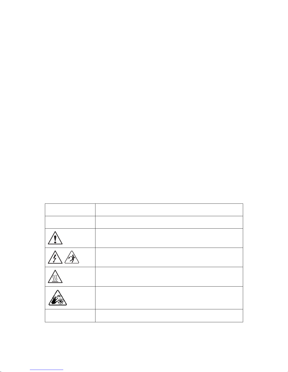
Table 1: Warning and Cautions
CAUTION
Indicates the presence of a hazard that may cause minor personal injury or
property damage if the CAUTION is ignored.
WAR NING
Indicates the presence of a hazard that may result in serious personal injury if
the WARNING is ignored.
Indicates potential hazard if indicated information is ignored.
Indicates shock hazards that result in serious injury or death if safety instructions are not followed.
Indicates hot components or surfaces.
Indicates do not touch fan blades, may result in injury.
Remove the system from the rack to disconnect power system.
Page 12
PRECAUTIONARY MEASURES
XI
Intended Application Uses
This product was evaluated as Information Technology Equipment (ITE), which may be
installed in offices, schools, computer rooms, and similar commercial type locations. The
suitability of this product for other product categories and environments (such as medical,
industrial, residential, alarm systems, and test equipment), other than an ITE application,
may require further evaluation.
Site Selection
The system is designed to operate in a typical office environment. Choose a site that is:
Clean, dry, and free of airborne particles (other than normal room dust).
Well-ventilated and away from sources of heat including direct sunlight and radia-
tors.
Away from sources of vibration or physical shock.
Isolated from strong electromagnetic fields produced by electrical devices.
Provided with a properly grounded wall outlet.
Provided with sufficient space to access the power system, because they serve as the
product's main power disconnect.
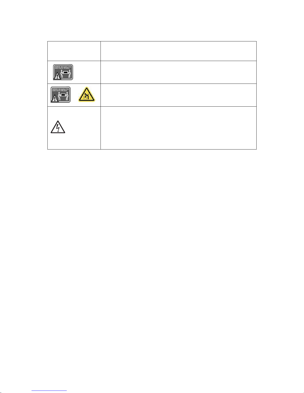
The enclosure is designed to carry only the weight of the system sled. Do not
use this equipment as a workspace. Do not place additional load onto any
equipment in this system.
Do not move racks by yourself. Due to the height and weight of the rack, a minimum of two people should accomplish this task.
Indicates two people are required to safely handle the system.
Restricted Access Location: The system is intended for installation only in a
Server Room or Computer Room where both these conditions apply:
access can only be gained by SERVICE PERSONS or by USERS who have
been instructed about the reasons for the restrictions applied to the location and about any precautions that shall be taken; and
access is through the use of a TOOL or lock and key, or other means of secu-
rity, and is controlled by the authority responsible for the location.
Table 1: Warning and Cautions (Continued)
Page 13
PRECAUTIONARY MEASURES
XII
Equipment Handling Practices
Reduce the risk of personal injury or equipment damage:
Conform to local occupational health and safety requirements when moving and
lifting equipment.
Use mechanical assistance or other suitable assistance when moving and lifting
equipment.
To reduce the weight for easier handling, remove any easily detachable compo-
nents.
Never lift or move your system soley by the handle on the component.
Power and Electrical Warnings
System Access Warnings
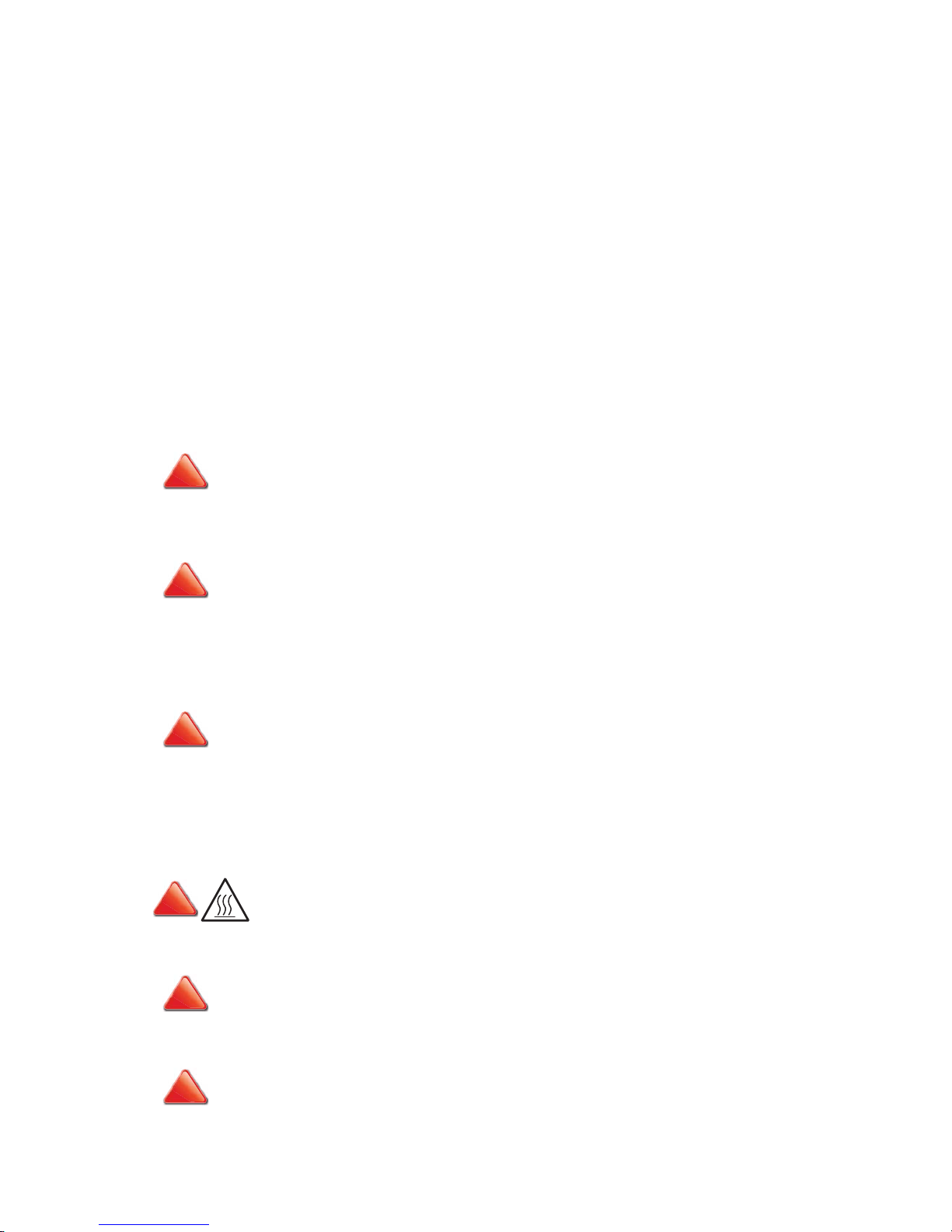
CAUTION!
MAKE SURE THE SYSTEM IS REMOVED FROM THE RACK BEFORE SERVICING ANY NON-HOT PLUG COMPONENTS.
T
HE BUS BAR CLIPS MUST BE DISCONNECTED FROM THE POWER SYSTEM INORDER TO FULLY SEPARATE THE SYS-
TEM FROM THE POWER SOURCE.
CAUTION!
TO AVOID RISK OF ELECTRIC SHOCK, DISCONNECT ALL CABLING FROM THE SYSTEM AND REMOVE THE SYSTEM
FROM THE RACK.
CAUTION!
TO AVOID PERSONAL INJURY OR PROPERTY DAMAGE, THE FOLLOWING SAFETY INSTRUCTIONS APPLY WHENEVER
ACCESSING THE INSIDE OF THE PRODUCT:
Disconnect from the power source by removing the system from the rack.
Disconnect all cabling running into the system.
Retain all screws or other fasteners when servicing. Upon completion servicing, sercure
with original screws or fasteners.
CAUTION!
IF THE SYSTEM HAS BEEN RUNNING, ANY INSTALLED COMPONENTS LINK HDD, MEMORY MODULES, HEAT
SINK, PROCESSOR AND CHIPSET MAY BE HOT.
CAUTION!
UNLESS YOU ARE ADDING OR REMOVING A HOT-PLUG COMPONENT, ALLOW THE SYSTEM TO COOL BEFORE SER-
VICING.
CAUTION!
TO AVOID INJURY DO NOT CONTACT MOVING FAN BLADES. IF YOUR SYSTEM IS SUPPLIED WITH A GUARD OVER THE
FAN, DO NOT OPERATE THE SYSTEM WITHOUT THE FAN GUARD IN PLACE.
!
!
!
!!!
Page 14

PRECAUTIONARY MEASURES
XIII
Rack Mount Warnings
The following installation guidelines are required by safety regulatory for maintaining
safety compliance when installing your system into a rack.
The equipment rack must be anchored to an unmovable support to prevent it from tipping when your system or piece of equipment is extended from it. The equipment rack
must be installed according to the rack manufacturer's instructions.
Install equipment in the rack from the bottom up, with the heaviest equipment at the bottom of the rack.
Extend only one piece of equipment from the rack at a time.
You are responsible for installing a main power disconnect for the entire rack unit. This
main disconnect must be readily accessible, and it must be labeled as controlling power to
the entire unit, not just to the system(s).
To avoid risk of potential electric shock, a proper safety ground must be implemented for
the rack and each piece of equipment installed in it.
Elevated Operating Ambient - If installed in a closed or multi-unit rack assembly, the operating ambient temperature of the rack environment may be greater than room ambient.
Therefore, consideration should be given to installing the equipment in an environment
compatible with the maximum ambient temperature (Tma) specified by the manufacturer.
Reduced Air Flow - Installation of the equipment in a rack should be such that the amount
of air flow required for safe operation of the equipment is not compromised.
Mechanical Loading - Mounting of the equipment in the rack should be such that a hazardous condition is not achieved due to uneven mechanical loading.
Circuit Overloading - Consideration should be given to the connection of the equipment
to the supply circuit and the effect that overloading of the circuits might have on over-current protection and supply wiring. Appropriate consideration of equipment nameplate
ratings should be used when addressing this concern.
Reliable Earthing - Reliable earthing of rack-mounted equipment should be maintained.
Particular attention should be given to supply connections other than direct connections
to the branch circuit (e.g. use of power strips).
Page 15

PRECAUTIONARY MEASURES
XIV
Electrostatic Discharge (ESD)
Always handle boards carefully. They can be extremely sensitive to ESD. Hold boards only
by their edges without any component and pin touching. After removing a board from its
protective wrapper or from the system, place the board component side up on a
grounded, static free surface. Use a conductive foam pad if available but not the board
wrapper. Do not slide board over any surface.
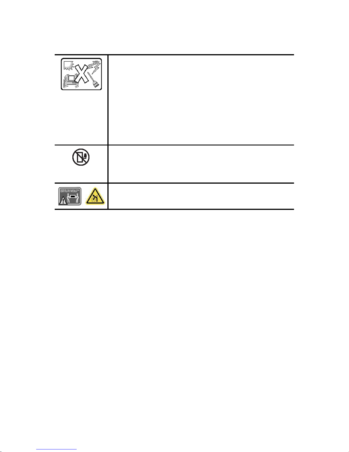
Cooling and Airflow
Please be aware that slots and openings on the front and rear side of the chassis are
designed for ventilation; to make sure reliable operation of your system and to protect it
from overheating, these openings must not be covered or blocked. The openings should
never be covered or blocked by placing the product on a bed, sofa, rug, or other similar
surface. This product should never be placed near or over a radiator or heat register, or in a
built-in installation unless proper ventilation is provided.
Laser Peripherals or Devices
Use certified and rated Laser Class I for Optical Transceiver product.
Heed safety instructions: Before working with the system, whether using this manual or
any other resource as a reference, pay close attention to the safety instructions. Adhere to
the assembly instructions in this manual to ensure and maintain compliance with existing
product certifications and approvals. Use only the described, regulated components spec-
CAUTION!
ESD CAN DAMAGE DRIVES, BOARDS, AND OTHER PARTS. WE RECOMMEND THAT YOU PERFORM ALL PROCEDURES
AT AN ESD WORKSTATION. IF ONE IS NOT AVAILABLE, PROVIDE SOME ESD PROTECTION BY WEARING AN ANTI-
STATIC WRIST STRAP ATTACHED TO CHASSIS GROUND -- ANY UNPAINTED METAL SURFACE -- ON YOUR SERVER
WHEN HANDLING PARTS.
CAUTION!
CAREFULLY ROUTE CABLES AS DIRECTED TO MINIMIZE AIRFLOW BLOCKAGE AND COOLING PROBLEMS. FOR
PROPER COOLING AND AIRFLOW, OPERATE THE SYSTEM ONLY WITH THE CHASSIS COVERS* / AIR DUCT*
INSTALLED. OPERATING THE SYSTEM WITHOUT THE COVERS / AIR DUCT* IN PLACE CAN DAMAGE SYSTEM PARTS .
T
O INSTALL THE COVERS* / AIR DUCT*:
Check first to make sure you have not left loose tools or parts inside the system.
Check that cables, add-in cards, and other components are properly installed.
Attach the covers* / air duct* to the chassis according to the product instructions.
* May not apply to all systems.
CAUTION!
TO AVOID RISK OF RADIATION EXPOSURE AND / OR PERSONAL INJURY:
Do not open the enclosure of any laser peripheral or device.
Laser peripherals or devices are not serviceable.
Return to manufacturer for servicing.
!
!
!
Page 16

PRECAUTIONARY MEASURES
XV
ified in this manual. Use of other products / components will void other safety regulatory
approvals of the product and will most likely result in non-compliance with product regulations in the region(s) in which the product is sold.
System power on/off: To remove power from system, you must remove the system from
rack. Make sure the system is removed from the rack before opening the chassis, adding,
or removing any non hot-plug components.
Hazardous conditions, devices and cables: Hazardous electrical conditions may be
present on power, telephone, and communication cables. Turn off the system and disconnect the cables attached to the system before servicing. Otherwise, personal injury or
equipment damage can result.
Electrostatic discharge (ESD) and ESD protection: ESD can damage drives, boards, and
other parts. We recommend that you perform all procedures in this chapter only at an ESD
workstation. If one is not available, provide some ESD protection by wearing an antistatic
wrist strap attached to chassis ground (any unpainted metal surface on the server) when
handling parts.
ESD and handling boards: Always handle boards carefully. They can be extremely sensitive to electrostatic discharge (ESD). Hold boards only by their edges. After removing a
board from its protective wrapper or from the system, place the board component side up
on a grounded, static free surface. Use a conductive foam pad if available but not the
board wrapper. Do not slide board over any surface.
Installing or removing jumpers: A jumper is a small plastic encased conductor that slips
over two jumper pins. Some jumpers have a small tab on top that can be gripped with fingertips or with a pair of fine needle nosed pliers. If the jumpers do not have such a tab,
take care when using needle nosed pliers to remove or install a jumper; grip the narrow
sides of the jumper with the pliers, never the wide sides. Gripping the wide sides can damage the contacts inside the jumper, causing intermittent problems with the function controlled by that jumper. Take care to grip with, but not squeeze, the pliers or other tool used
to remove a jumper, or the pins on the board may bend or break.
General Information
The information about rack and the wording “rack” in this technical guide supports the
organization of Open Compute definition.
The term Rack as found in this technical guide referes to the term Rack or Open Rack as
described and used in the Open Compute Project definition.
Before servicing this system, it is recommened to read this technical guide completely to
be aware of any safety issues or requirements involved in the servicing of this system.
Page 17
PRECAUTIONARY MEASURES
XVI
Assembly Safety Guidelines
The system is designed to operate in a typical office environment.
Choose a site that is:
Clean and free of airborne particles (other than normal room dust).
Well ventilated and away from sources of heat including direct sunlight.
Away from sources of vibration or physical shock.
Isolated from strong electromagnetic fields produced by electrical devices.
In regions that are susceptible to electrical storms, we recommend you plug
your system into a surge suppressor and disconnect telecommunication lines
to your modem during an electrical storm.
Provided with a properly grounded wall outlet.
Provided with sufficient space to access the power system, because they
serve as the product's main power disconnect.
WARNING!
The system is safety certified as rack-mounted equipment for use in a server
room or computer room, using an approved customer rack.
The enclosure is designed to carry only the weight of the system sled. Do not
place additional load onto any equipment.
Heavy object. Indicates two people are required to safely handle the system.
Page 18

PRECAUTIONARY MEASURES
XVII
Structure of this guide
Chapter 1: About the System
“This section introduces the system, its different configuration(s) and the main
features.”
Chapter 2: Installing Hardware
“This section provides guidance information to properly service components in
the system.”
Chapter 3: BIOS
“This section provides information regarding the BIOS architecture, BIOS update
utility, server management, checkpoints, and error handling found in the F03A.”
Chapter 4: ESMS Functional Specification
“This section provides information on the server managment software, its key
features and the management engine.”
Chapter 5: Connectors and Jumpers
“This section provides guidance information for the position and configuration
of connectors and jumpers.”
Chapter 6: Troubleshooting
“This section provides a guidance for the troubleshooting of system errors and
hardware failure notification.”
Chapter 7: Regulatory and Compliance Information
“This section provides regulatory and compliance information applicable to this
system.”
Page 19

About the System
Chapter 1
This section introduces the system, its different configuration(s) and the main features.
Page 20
INTRODUCTION ABOUT THE SYSTEM
1-1
1.1 Introduction
High Density 2U4N design for maximum performance
The Rackgo X F03A is designed for the highest compute density with four nodes in a 2 OU
space. Each node can install up to two SATADOMs for the operating system and up to four
extra hot-swappable SSD/HDDs for cache or data storage. Its RAID-ready configuration
preserves data integrity and avoids data corruption.
Vanity Free Design for better MTBF
By centralizing power supplies in the rack and removing unnecessary components from
the system, the F03A enhances system MTBF by 58% compared to other conventional
2U4N systems in the market. This will avoid system downtime caused by component failure and minimize maintenance efforts.
VGA-redirection for on-site troubleshooting
F03A offers an optional dual-port 10Gbps SFP+ mezzanine card with an ASPEED 2300
chip, providing VGA-redirection for datacenters requiring on-site troubleshooting.
Specifications
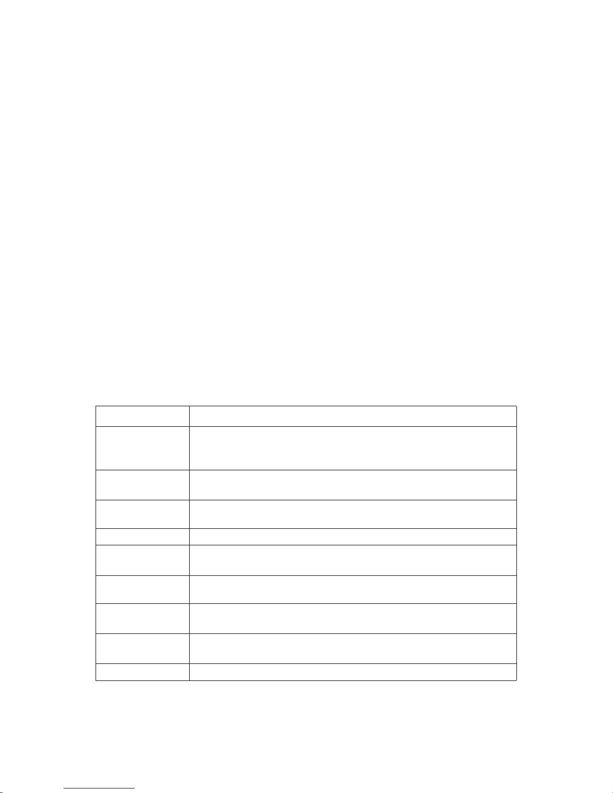
Table 1: System Specifications
SPECIFICATION DESCRIPTION
Form Factor (LxWxH)
2 OU Rackmount, 4 nodes
839.47mm x 535.94mm x 92.96mm
33.05" x 21.1" x 3.66"
MB Size (WxL)
165.1mm x 508mm
6.5" x 20"
Processor
(2) Intel® Xeon® processor E5-2600/ E5-2600 v2 product family per node, up to
130W
Chipset Intel® C602 chipset
SAS Controller
Intel® C602 upgrade ROM #1 (optional)
Intel® C602 upgrade ROM #2 (optional)
Memory
(16) DDR3 800/1066/1333/1600/1866 MHz ECC UDIMM/RDIMM/LRDIMM slots per
node
Drive Bay
SKU 1: (2) 2.5" SATA/SAS hot-plug HDD trays per node
SKU 1: (4) 2.5" SATA/SAS hot-plug HDD trays per node
Onboard Storage
Device
(3) Mini-SAS connectors signal from Intel® C602
(2) SATA connectors signal from Intel® C602
HDD Backplane 1 to 1
Page 21
ABOUT THE SYSTEM INTRODUCTION
1-2
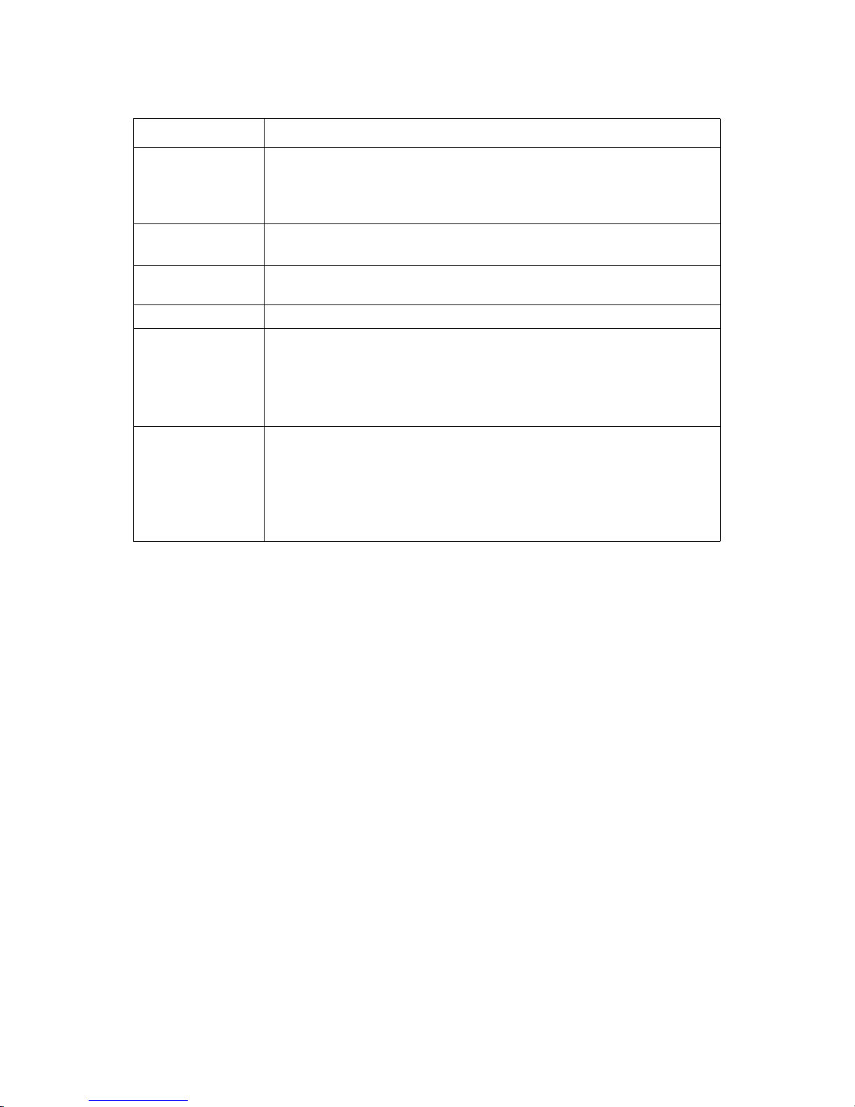
* All specifications and figures are subject to change without prior notice.
PCIe Expansion Slot
SKU 1: (2) PCIe x8 G3 riser slots for low-profile card per node
SKU 2: (1) PCIe x8 G3 riser slots for low-profile card per node
Both SKU 1 and SKU 2 have (1) PCIe x8 G3 dedicated OCP network mezzanine
card slot per node
SW RAID Options
Intel® C602 upgrade ROM #1 RAID 0/1/10 for SCU (optional)
Intel® C602 upgrade ROM #2 SAS RAID 0/1/10/5 for SCU (optional)
Management Network
(1) Dedicated Intel® 82574 GbE RJ45 port for onboard management
Integrated Graphics AST2300 (optional with 10G SFP+ mezzanine card)
Front I/O
(1) USB port per node
(1) OCP debug header per port
(1) Dedicated Rj45 management port
(1) Power button
(1) Reset button
Operating Environment
Gaseous Contamination: Severity Level G1 per ANSI/ISA 71.04-1985
Ambient operating temperature range: -5C to +35C
Operating and Storage relative humidity: 10% to 90% (non-condensing)
Storage temperature range: -40C to +70C
Transportation temperature range: -55C to +85C (short-term storage)
Operating altitude with no de-ratings: 1,000m (3,300 feet)
Table 1: System Specifications (Continued)
SPECIFICATION DESCRIPTION
Page 22
A TOUR OF THE SYSTEM ABOUT THE SYSTEM
1-3
1.2 A Tour of the System
System Overview
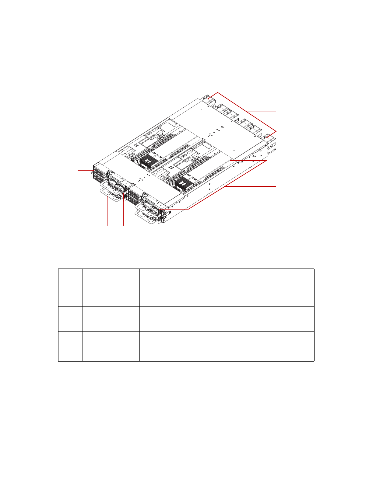
Figure 1-1. System Component Overview
Table 2: Component Overview
NO.ITEM DESCRIPTION
1 Fan module System fan modules (x6). See Fan Module on page 2-6.
2 Sled Four sled assemblies. See Node Front View on page 1-6.
3 Tray release Press to unlock the sled assembly from the chassis.
4 Tray handle Hold to remove the sled assembly from the chassis.
5 Chassis release latch Hold to remove the chassis from the rack.
6 HDD Tray
Pull handle to remove hard disk drives tray. See Hard Disk Drive Tray on
page 2-36.
34
5
2
6
1
Page 23
ABOUT THE SYSTEM SYSTEM OVERVIEW
1-4
System Front View
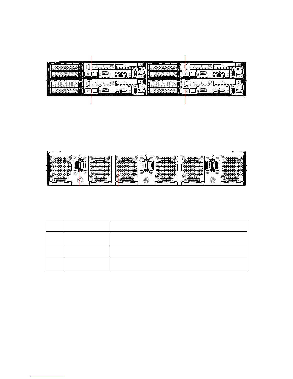
Figure 1-2. System Front View
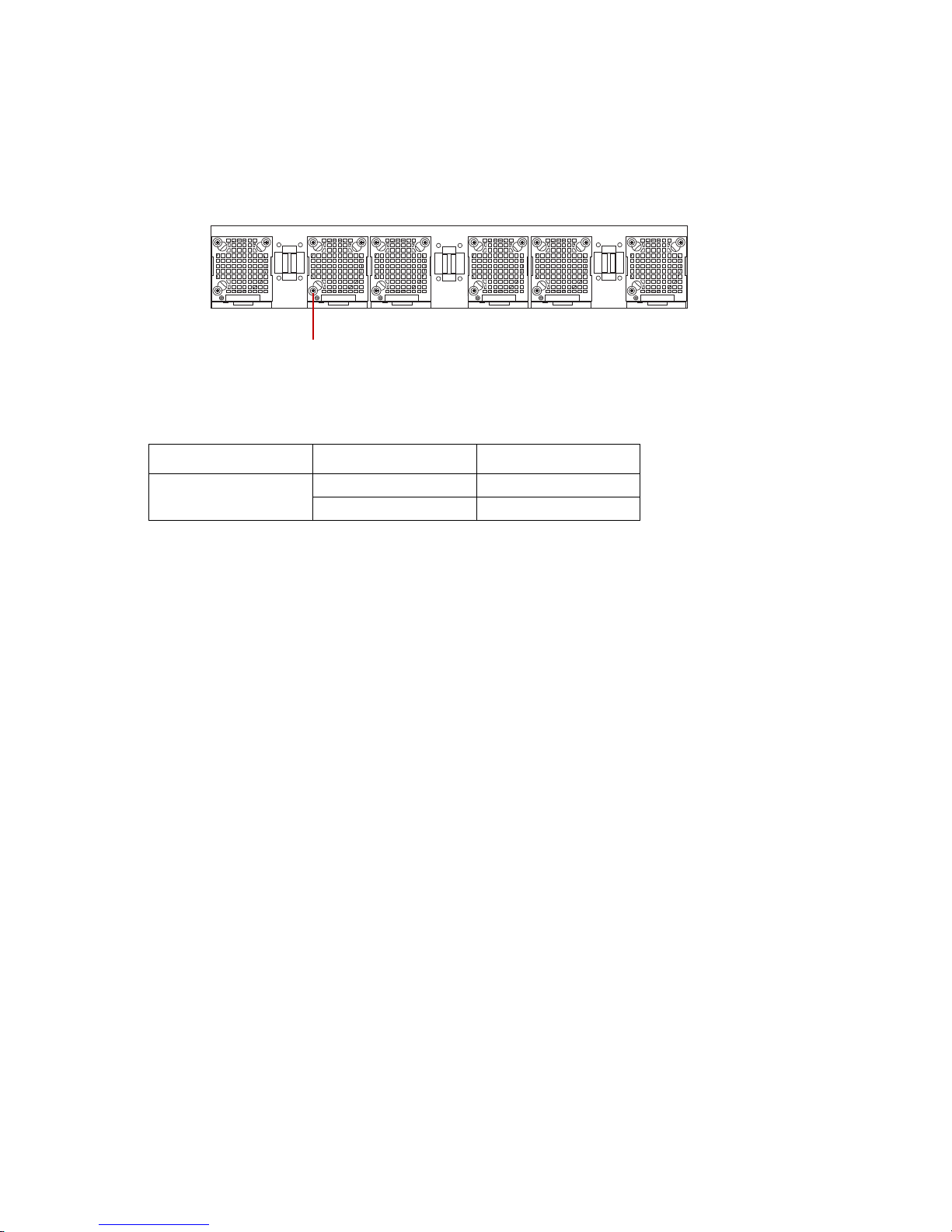
System Rear View
Figure 1-3. System Rear View
Table 3: Rear Panel View
NO.NAME DESCRIPTION
1
Bus bar connector
assembly
Bus bar connector assemblies for power input (x3)
2 Air grill Air grills for heat discharge (x6)
3Fan module
Fan modules are located inside the air grills. See Fan Module on page 26
compute node 1 compute node 3
compute node 4compute node 2
1 2 3
Page 24
SYSTEM OVERVIEW ABOUT THE SYSTEM
1-5
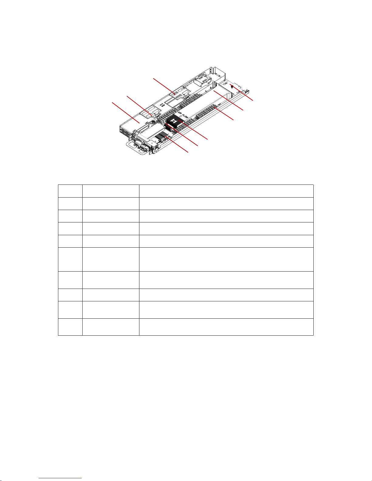
Node Overview
Figure 1-4. Node Component Overview
Table 4: Component Overview
NO.ITEM DESCRIPTION
1 Interposer board A board connects both motherboard and middle plane board
2 Air duct Direct the air flow on the processor
3DIMM Memory modules
4 CPU Support the computing power to system
5 Mainboard
A printed circuit board that implements the components like CPU
socket, memory slots, chipsets, expansion slots and I/O ports to provide
the system hardware features
6
Mezzanine board
connector
Connects to Quanta's OCP Mezzanine board (optional)
7 HDD Tray Tray that suppor ts
up to two SAS/SATA hard disk drives
8 PCIe riser bracket
Features one or two PCIe slots for the installation of expansion cards
(low-profile cards) (optional)
9iBBU
Intelligent Battery Backup Unit (optional) supports the storage PCIe
card (optional)
2
3
4
6
5
1
9
8
7
Page 25
ABOUT THE SYSTEM SYSTEM OVERVIEW
1-6
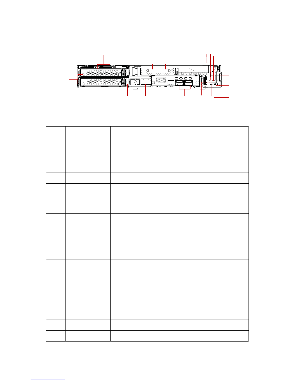
Node Front View
Figure 1-5. Node Front View
Table 5: Node Front View
NO.ITEM DESCRIPTION
1 HDD tray
Each HDD board can support up to 2 SAS/SATA HDDs
Tray is connected through an internal miniSAS and power cable to
Windmill MB SAS/SATA board
2
External mini-SAS
port
Supports up to 6 GB SAS connection (optional)
3 USB Standard USB 2.0 connector
4Power button
Press less than four seconds to activate power management event.
Press longer than four seconds to activate a hard power off.
5Reset button
Press to perform a hard reset and begin executing the BIOS initialization code.
6 Sled release latch Press and hold to release the system sled.
7
Power LED
(Blue)
Displays during power on state.
Blinking state indicates system ID event trigger. See Mainboard LEDs on
page 1-7.
8
HDD activity LED
(Green)
Displays during activity on the motherboard's SATA hard drive interfaces. See Mainboard LEDs on page 1-7.
9
Beep error LED
(Amber)
Provides PC speaker functionality by illuminating the LED in place of
the PC speaker audible tone. See Mainboard LEDs on page 1-7.
10 Debug header
14-pin (shrouded), right-angled, 2mm pitch connector; supports hot
plugging for existing debug cards.
Two 7-segment LED: displays firmware POST information and sys-
tem error codes.
One RS-232 serial connector: provides console redirection.
One reset switch: triggers system reset when pressed.
Designed with a notch for easy installation to avoid pin shifting.
11 NIC 10 Gb SFP + connectors (optional)
12 VGA Provides interface for an external display (optional)
13
1
1112
234
5
6
9
7
10
8
15
14
Page 26
LED DEFINITIONS ABOUT THE SYSTEM
1-7
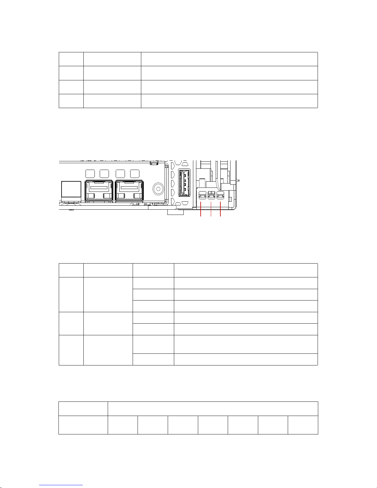
LED Definitions
Mainboard LEDs
Figure 1-6. Mainboard LED Description
Beep Error LED Listing
13 Service NIC Service Network Interface Controller port for management
14 Tray release Press and hold to release the HDD tray.
15 HDD tray LED Upper and lower HDD Tray Dual (Active/Fault) LED
Table 6: Mainboard LED Description
NO.NAME STATE DESCRIPTION
1Power LED
Solid Blue Powered on state.
Blinking Blue ID function activated.
Off System is powered off.
2 HDD activity LED
Solid Green Activity detected on mainboard’s SATA interfaces.
Off No activity detected.
3 Beep error LED
Solid Amber
Provides PC speaker error functionality. See Beep Error
LED Listing on page 1-7.
Off No fault detected.
Table 7: Beep Error LED Listing
ERROR DESCRIPTION LED PATTERNS
Memory refresh
timer error
On (2sec)
Off
(0.25sec)
On (2sec)
Off
(0.25sec)
On (2sec) Off (3sec) ...(repeat)
Table 5: Node Front View (Continued)
NO.ITEM DESCRIPTION
321
Page 27
ABOUT THE SYSTEM LED DEFINITIONS
1-8
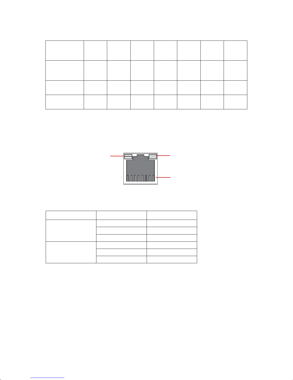
LAN Port LEDs
The mainboard has an Intel® 82574L Ethernet interface to the front RJ45 connector. Each
RJ45 connector has two built-in LEDs, see the following table for further details.
Figure 1-7. RJ45 LAN Port LEDs
Base Memory
read/write test
error
On (2sec)
Off
(0.25sec)
On (2sec)
Off
(0.25sec)
On
(0.25sec)
Off (3sec) ...(repeat)
Keyboard controller BAT test
error
On
(0.25sec)
Off
(0.25sec)
On
(25sec)
Off
(0.25sec)
On (2sec)
General exception error
On (2sec)
Off
(0.25sec)
On
(25sec)
Off
(0.25sec)
On
(0.25sec)
Off (3sec) ...(repeat)
Display memory
error
On
(0.25sec)
Off
(0.25sec)
On
(25sec)
Off
(0.25sec)
On
(0.25sec)
Table 8: LAN Port LED Definition
LED STATUS DESCRIPTION
Link LED
OFF No link
Solid Green Link
Blinking Green Link with access
Speed LED
Off No link
Green 100 Mb
Amber 1 Gb
Table 7: Beep Error LED Listing (Continued)
link & activity speed
pin 1 location
Page 28
LED DEFINITIONS ABOUT THE SYSTEM
1-9
Fan LED
The system supports six hot-swap fan modules connected through the midplane board.
The fan module LEDs are located on each fan module, see the following illustration.
Figure 1-8. Fan Module LED
Table 9: Fan LED Definition
LED STATUS DESCRIPTION
Fan LED
Blue Fan failure
Off No failure
fan LED location
Page 29

Installing Hardware
Chapter 2
This section provides guidance information to properly service components in the system.
Page 30

SAFETY MEASURES INSTALLING HARDWARE
2-1
2.1 Safety Measures
WARNING!
Always ask for assistance to move or lift the system.
WARNING!
Only perform troubleshooting as authorized by the product documentation, or as directed by
a service and support team. Repairs not authorized by warranty may void the warranty and
damage the system.
WARNING!
Always make sure to disconnect the system from the power source. Powering down the system DOES NOT ensure there is no electrical activity in the system.
WARNING!
Server components and circuit boards are easily damaged by discharges of static electricity.
Working on servers that are connected to a power system can be extremely dangerous. Follow
the guidelines below to avoid personal injury or damage to the server.
WARNING!
Always disconnect the system from the power source whenever you are working inside the
server case.
WARNING!
Wear a grounded wrist strap. If none are available, discharge any personal static electricity by
touching the bare metal chassis of the server case, or the bare metal body of any other
grounded device.
WARNING!
Humid environments tend to have less static electricity than dry environments. A grounding
strap is warranted whenever danger of static electricity exists.
WARNING!
Do not touch the components on the unless it is necessary to do so. Do not flex or stress circuit
boards.
WARNING!
Leave all replacement components inside their static-proof packaging until you are ready to
use them.
!
!
!
!
!
!
!
!
!
Page 31

INSTALLING HARDWARE SLED TRAY
2-2
2.2 Sled Tray
The server consists of four (4) removable sled trays. Each one has independent motherboard with CPU, memory and PCIe slots.
Releasing the Sled Tray
1. Locate the sled to remove. See System Front View on page 1-4.
2. Press and hold the tray release lever.
Figure 2-1. Releasing a Sled Tray
3. Hold the tray handle and pull the tray out of the chassis.
Securing a Sled Tray
1. Align the sled tray with the chassis bay.
2. Grasp the tray handle and slide the tray into the chassis.
CAUTION!
ENSURE ALL POWER IS DISCONNECTED FROM THE SYSTEM BEFORE PROCEEDING.
CAUTION!
THIS UNIT IS HEAVY. TO AVOID ANY POTENTIAL INJURY, TAKE PRECAUTION WHEN MOVING OR SERVICING THE
UNIT.
CAUTION!
THE SLED TRAY MUST BE FULLY EXTENDED AND LOCKED IN THE OPEN POSITION BEFORE SERVICING TO PREVENT
PERSONAL INJURY OR DAMAGE TO THE HARDWARE.
!!!
Page 32

SECURING A SLED TRAY INSTALLING HARDWARE
2-3
3. Continue to push the tray until it is seated with the chassis, and locks in place.
Figure 2-2. Releasing a Sled Tray
Page 33

INSTALLING HARDWARE AIR DUCT
2-4
2.3 Air Duct
The air duct is a espcially designed to allows air flow to improve ventilation inside the sled
tray and prevent system overheat.
Removing an Air Duct
1. Locate the air duct on the sled tray.
2. Position your thumb over the bottom of the air duct, see following illustration.
Figure 2-3. Removing an Air Duct
3. Press the air duct outward to release it from the standoffs.
CAUTION!
ENSURE ALL POWER IS DISCONNECTED FROM THE SYSTEM BEFORE PROCEEDING.
CAUTION!
TO PREVENT SYSTEM OVERHEATING, ENSURE THAT THE AIR DUCT IS CLOSED AND PROPERLY SEATED WHEN THE
SYSTEM IS POWERED ON.
!
!
Page 34

INSTALLING AN AIR DUCT INSTALLING HARDWARE
2-5
4. Slide the air duct and lift it up to remove.
Figure 2-4. Removing an Air Duct
Installing an Air Duct
1. Align the air duct over the chassis, see the following illustration.
2. Align the air duct with the standoffs on the sled tray.
3. Slide the air duct under the standoffs to seat in place.
Figure 2-5. Installing Air Duct
CPU0C
P
U0
Air
Page 35

INSTALLING HARDWARE FAN MODULE
2-6
2.4 Fan Module
The system fan cage includes six (6) fan modules. The modules can be removed and
installed.
In the following illustration the fan modules are numbered as defined by the location on
the midplane board.
Figure 2-6. Fan Module Identification
Removing a Fan Module
The system supports six hot-swap fan modules.
1. Locate the fan assembly to remove.
2. Press up on the tray release lever on the fan tray.
CAUTION!
ENSURE ALL POWER IS DISCONNECTED FROM THE SYSTEM BEFORE PROCEEDING.
0 1 2 3 4 5
!
Page 36

REMOVING A FAN MODULE INSTALLING HARDWARE
2-7
3. Pull the fan assembly out to remove from the chassis.
Figure 2-7. Removing the Fan Assembly
4. Disconnect the fan cable from the fan board.
Figure 2-8. Disconnecting the Fan Cable
5. Remove the screws securing the fan board.
Page 37

INSTALLING HARDWARE REMOVING A FAN MODULE
2-8
6. Remove the fan board from the tray.
Figure 2-9. Removing the Screws and the Fan Board
7. Remove the screws securing the fan module to the fan tray.
Figure 2-10. Removing the Fan Tray Screws
8. Carefully pull out the fan LED from the tray.
Page 38

INSTALLING A FAN MODULE INSTALLING HARDWARE
2-9
9. Remove the fan module from the fan tray.
Figure 2-11. Removing a Fan Module
Installing a Fan Module
1. Locate the fan LED and insert in the fan tray.
CAUTION!
POSITION THE FAN MODULE CORRECTLY, TO AVOID SEVERE SYSTEM OVERHEATING.
fan LED
fan LED
in fan tray
!
Page 39

INSTALLING HARDWARE INSTALLING A FAN MODULE
2-10
2. Align the fan module in the fan tray and install.
Figure 2-12. Installing the Fan Module in Tray
3. Secure the fan module with the provided screws.
Figure 2-13. Securing the Fan Module to the Tray
4. Align the fan board with the screw holes on the tray and install the fan board.
5. Secure with the provided screws.
fan LED
fan LED
in fan tray
Page 40

INSTALLING A FAN MODULE INSTALLING HARDWARE
2-11
6. Connect the fan cable to the fan board.
Figure 2-14. Connecting the Fan Cable
7. Align the fan assembly with the chassis bay.
8. Install the fan assembly and push the fan assembly until it is correctly seated in the
chassis. The fan assembly locks in place.
Figure 2-15. Installing the Fan Assembly
Page 41

INSTALLING HARDWARE MIDPLANE BOARD
2-12
2.5 Midplane board
The midplane board serves as a bridge between the power system and the nodes.
Removing the Midplane
1. Power off the sled tray by sliding the sled tray out of the chassis. See Releasing the
Sled Tray on page 2-2.
2. Place the sled tray on a clean work surface.
3. Remove the enclosure from the rack. Place the enclosure on a clean work surface.
4. Remove the rear assembly.
Figure 2-16. Removing rear assembly
CAUTION!
ENSURE ALL POWER IS DISCONNECTED FROM THE SYSTEM BEFORE PROCEEDING.
!
A
IR
FL
OW
CPU0C
P
U0
Air
A
IR
FL
OW
Page 42

REMOVING THE MIDPLANE INSTALLING HARDWARE
2-13
5. Remove the bus bar cabling from the midplane.
Figure 2-17. Removing Bar Cabling
6. Move the cabling out of the way to prevent interference with the remaining procedure.
7. Remove the securing screws from the midplane and rear assembly.
8. Slide the midplane from left to right to unlock the midplane from the standoffs on
the rear assembly.
9. Remove the midplane board.
Figure 2-18. Removing the midplane
Page 43

INSTALLING HARDWARE INSTALLING THE MIDPLANE
2-14
Installing the Midplane
Make sure the enclosure is on a clean work surface before starting this procedure.
1. Align the midplane board with the standoffs on the rear assembly.
2. Slide the midplane from right to left to lock the midplane on the rear assembly.
Figure 2-19. Installing the midplane
3. Secure the midplane and rear assembly with the provided screws.
Figure 2-20. Installing the midplane
Page 44

INSTALLING THE MIDPLANE INSTALLING HARDWARE
2-15
4. Replace the bus bar cabling on the midplane.
Figure 2-21. Replace BUS cables
5. Replace the rear assembly on the enclosure.
6. Replace the enclosure on the rack.
7. Replace all the sled trays in the chassis. See Securing a Sled Tray on page 2-2.
Page 45

INSTALLING HARDWARE DIMMS
2-16
2.6 DIMMS
This section includes the following information:
Memory population rules
DIMM installation procedures
Banks and Channels
The channels are designated a letter A for a single processor and B for dual processors
configuration.
Each bank is also identified by a designation, either 1 or 2. See the following illustration for
the bank and channel layout on the mainboard.
Figure 2-22. Bank and Channel Layout
Note:
Before installing or replacing memory modules, read the following information to become
familiar with memory performance guidelines and population rules. The information is provided as guidance for best server performance practices.
rz
Note:
Note that slots 0, 2, 4, and 6 within a bank are colored coded in white, while slots 1, 3, 5, and 7
are black.
CPU
0
CPU
1
A0, A1, A2, A3B0, B1, B2, B3
A4, A5, A6, A7B4, B5, B6, B7
Front SideRear Side
Page 46

MEMORY POPULATION RULES INSTALLING HARDWARE
2-17
Memory Population Rules
When considering the memory configuration of your server, you should consider the following items:
DIMMs within the server should all be the same size, speed, and type. It is not recom-
mended to mix different sized or different speed DIMMs in the same system. Mixing
DIMM modules results in the system setting the memory speed to that of the slowest installed DIMMs.
There are white and black DIMM slots. Populate the white slots in a bank first.
DIMMs can be used either in a one DIMM per Channel (1DPC) configuration or in a
two DIMMs per Channel (2DPC) configuration.
Low-voltage (1.35 V) DIMM and standard-voltage DIMM (1.5 V) can be mixed in the
system. However, the system BIOS defaults to standard-voltage operation.
The following denotes the memory support matrix.
Table 1: Memory Support Matrix
2 SPC
1 DPC 2 DPC
1.5V
SR/DR 1600 1600
QR 1066 800
LRDIMM 1333 1333
1.35V
SR/DR 1600(*) 1333
QR 1066(*) 800
LRDIMM 1333(*) 1333(*)
Table 2: Memory Population Configuration
DIMM_A1 DIMM_A2 DIMM_B1 DIMM_B2 Mirror Spare Lockstep
Configuration 1 x
Configuration 2 x
Configuration 3 x x o
Configuration 4 x x o
Configuration 5 x x o o
Configuration 6 x x x
Configuration 7 x x x
Configuration 8xxxxooo
x: Indicates the DIMM population location.
o: Indicates the supported function.
Page 47

INSTALLING HARDWARE REMOVING A MEMORY MODULE
2-18
Removing a Memory Module
1. Power off the sled tray by sliding the sled tray out of the chassis. See Releasing the
Sled Tray on page 2-2.
2. Place the sled tray on a clean work space.
3. Remove the air duct. See Removing an Air Duct on page 2-4.
4. Press down on the two ejector levers at both ends of the DIMM slot. The memory
module partially ejects.
5. Hold the DIMM module by the ends and remove it from the system. Place the DIMM
module in an antistatic packaging.
Figure 2-23. Removing a Memory Module
Installing a Memory Module
1. Locate the DIMM slot to populate and open the ejector levers at both ends of the
DIMM slot.
2. Align the notch on the DIMM module with the protrusion on the slot.
CAUTION!
HANDLE THE MEMORY MODULE BY THE EDGES AT ALL TIMES.
WARNING!
Memory modules remain hot after the system is powered down. Allow sufficient time for the
memory modules to cool before handling system components.
CAUTION!
HANDLE THE MEMORY MODULE BY THE EDGES AT ALL TIMES.
!
!
!
Page 48

INSTALLING A MEMORY MODULE INSTALLING HARDWARE
2-19
3. Press down on both corners of the DIMM module until the ejector levers lock in
place.
Figure 2-24. Installing Memory Module
4. Replace the air duct. See Removing an Air Duct on page 2-5.
5. Lift the sled tray and align it with the chassis bay.
6. Slide the sled tray in the chassis. See Securing a Sled Tray on page 2-2.
Page 49

INSTALLING HARDWARE INTELLIGENT BATTERY BACKUP UNIT (OPTIONAL)
2-20
2.7 Intelligent Battery Backup Unit (optional)
A single iBBU provides backup functionality for a single module. To provide backup functionality for all four modules, each module must have an iBBU installed.
Removing an iBBU
1. Remove the sled trays from the chassis. See Releasing the Sled Tray on page 2-2.
2. Place the tray on a clean work surface.
3. Locate the iBBU and disconnect the iBBU cable from the battery.
Figure 2-25. Disconnecting the iBBU Cable
4. Remove screw securing the iBBU assembly to the chassis.
Figure 2-26. Removing iBBU Assembly Screws
5. Remove the iBBU assembly.
Page 50

INSTALLING AN IBBU INSTALLING HARDWARE
2-21
6. Remove screws securing the battery to the bracket.
Figure 2-27. Removing the iBBU from the Bracket
Installing an iBBU
1. Locate the sled tray and remove it from the chassis. Place it on a clean work surface.
See Releasing the Sled Tray on page 2-2.
2. Align the iBBU battery and bracket screw holes, and install the iBBU on the bracket.
3. Secure with the provided screws.
Figure 2-28. Installing the iBBU Bracket
4. Align the iBBU assembly and chassis screw holes.
Page 51

INSTALLING HARDWARE INSTALLING AN IBBU
2-22
5. Secure with the provided screws
Figure 2-29. Installing the iBBU Assembly
6. Connect the iBBU cable to the battery
Figure 2-30. Connecting the iBBU Cable
7. Connect the iBBU cable to the expansion card.
8. Lift the sled tray and align it with the chassis bay.
9. Slide the sled tray in the chassis. See Securing a Sled Tray on page 2-2.
Note:
The iBBU can be connected to either a mezzanine card or an expansion card.
Page 52

PROCESSOR HEAT SINKS INSTALLING HARDWARE
2-23
2.8 Processor Heat Sinks
The system requires two heat sinks, one over each processor. There are design differences
between the heat sinks, however, the procedure for servicing each heat sink is the same.
For servicing purposes, a single design is used in the following procedures.
Removing a Processor Heat Sink
1. Power off the sled tray by sliding the sled tray out of the chassis. See Releasing the
Sled Tray on page 2-2.
2. Place the sled tray on a clean work surface.
3. Remove the air duct. See Removing an Air Duct on page 2-4.
4. Loosen captive screws securing the heat sink to the mainboard.
5. Remove the heat sink.
Figure 2-31. Removing the Heat Sink
WARNING!
The heatsink remains hot after the system has been powered down. Allow sufficient time to
cool before handling system components.
WARNING!
To prevent system overheating, ensure that the air duct is closed and properly seated when
the system is powered on.
!
!
Page 53

INSTALLING HARDWARE INSTALLING A PROCESSOR HEAT SINK
2-24
6. Repeat for the remaining heat sink.
Figure 2-32. Removing the Heat Sink
Installing a Processor Heat Sink
1. Align the heat sink over the processor plate making sure the arrow marking the air
flow is pointing towards the rear of the node.
2. Align the screws with the screw posts on the mainboard.
3. Tighten the screw in a sequential order. See the following drawing.
Figure 2-33. Installing the Heat Sink
Page 54

INSTALLING A PROCESSOR HEAT SINK INSTALLING HARDWARE
2-25
4. Repeat for the remaining heat sink.
Figure 2-34. Installing the Heat Sink
5. Replace the air duct. See Removing an Air Duct on page 2-5.
6. Lift the sled tray and align it with the chassis bay.
7. Slide the sled tray in the chassis. See Securing a Sled Tray on page 2-2.
Page 55

INSTALLING HARDWARE PROCESSORS
2-26
2.9 Processors
Removing a Processor
1. Pull the locking lever of the processor socket out and up as shown.
Figure 2-35. Releasing the Locking Lever
2. Pull the locking lever at the other side as shown below.
Figure 2-36. Lifting Processor Load Plate
Note:
All the instructions and images in this section are for illustration purposes only and may not
reflect the actual product.
WARNING!
The processor remains hot after the system has been powered down. Allow sufficient time to
cool before handling system components.
!
Page 56

INSTALLING A PROCESSOR INSTALLING HARDWARE
2-27
3. Lift and remove the processor.
Figure 2-37. Removing Processor
Installing a Processor
1. Open each of the processor locking levers in the order indicated, and then open the
processor cover.
2. Align the gold triangle identifying pin 1 of the processor with the triangular cutout
of the processor, and the indents on processor with the tabs on the socket.
3. Lift the processor load plate.
Figure 2-38. Installing Processor
Page 57

INSTALLING HARDWARE INSTALLING A PROCESSOR
2-28
4. Remove the processor dust cover.
5. Locate the pin-1 (A) on processor and the pin-1 (B) corner of the socket.
6. Locate the indents (C) on processor and corresponding tab (D) on socket.
7. Install the processor.
Figure 2-39. Installing Processor
8. Replace the processor load plate and locking lever to lock the processor in place.
Figure 2-40. Locking Processor
9. Repeat steps for the second processor.
Note:
Use the socket cover to protect the socket when the socket is empty.
B
C
D
A
Page 58

INTERPOSER BOARD INSTALLING HARDWARE
2-29
2.10 Interposer Board
The interposer board is a board between the mainboard and the mid-plane board. It
passes power and fan signals between these boards.
Removing the Interposer Board
1. Power off the sled tray by sliding the sled tray out of the chassis. See Releasing the
Sled Tray on page 2-2.
2. Place the sled tray on a clean work surface.
3. Locate the interposer board behind the mainboard.
4. Loosen the captive screw.
5. Slide out and remove the interposer board.
Figure 2-41. Removing the interposer board
Installing the Interposer Board
CAUTION!
ENSURE ALL POWER IS DISCONNECTED FROM THE SYSTEM BEFORE PROCEEDING.
CAUTION!
ENSURE ALL POWER IS DISCONNECTED FROM THE SYSTEM BEFORE PROCEEDING.
!
!
Page 59

INSTALLING HARDWARE INSTALLING THE INTERPOSER BOARD
2-30
1. Align the interposer board with the connector on the mainboard and slide until it is
seated correctly.
2. Tighten the captive screw.
3. Lift the sled tray and align it with the chassis bay.
4. Slide the sled tray in the chassis. See Securing a Sled Tray on page 2-2.
Figure 2-42. Installing the interposer board
Page 60

MEZZANINE BOARD (OPTIONAL)INSTALLING HARDWARE
2-31
2.11 Mezzanine Board (optional)
The mainboard has one slot for a single PCIe x8 mezzanine board.
Removing the Mezzanine Board
1. Power off the sled tray by sliding the sled tray out of the chassis. See Releasing the
Sled Tray on page 2-2.
2. Place the sled tray on a clean work surface.
3. Remove the securing screw from the bracket.
4. Remove the bracket from the mezzanine board.
Figure 2-43. Removing the Mezzanine Board
5. Push the securing clips outward to free the mezzanine board and lift the mezzanine
board to release from the two securing clips.
6. Remove the mezzanine board from the mainboard.
7. Carefully turn the mezzanine board over and disconnect the USB cable.
8. Release the USB cable from the clip.
CAUTION!
ENSURE ALL POWER IS DISCONNECTED FROM THE SYSTEM BEFORE PROCEEDING.
!
Page 61

INSTALLING HARDWARE INSTALLING THE MEZZANINE BOARD
2-32
9. Place the mezzanine board in an anti- static bag.
Figure 2-44. Removing the Mezzanine Board
Installing the Mezzanine Board
1. The mezzanine board requires the attachment of a mezzanine sponge (with mylar).
Align the sponge to the mezzanine board along the marked area.
2. Connect the USB cable to the mezzanine card connector.
3. Align the holes located at one end of the mezzanine card with the guide posts on
the securing clips.
4. Lower the mezzanine board and gently press down to secure with the clips.
Figure 2-45. Installing the Mezzzanine Board
5. Align the bracket with the I/O ports on the mezzanine board.
Page 62

INSTALLING THE MEZZANINE BOARD INSTALLING HARDWARE
2-33
6. Install in place and secure the bracket with the provided screw.
Figure 2-46. Installing the Mezzanine Bracket
7. Lift the sled tray and align it with the chassis bay.
8. Slide the sled tray in the chassis. See Securing a Sled Tray on page 2-2.
Page 63

INSTALLING HARDWARE MAINBOARD
2-34
2.12 Mainboard
Removing a Mainboard
1. Power off the sled tray by sliding the sled tray out of the chassis. See Releasing the
Sled Tray on page 2-2.
2. Place the sled tray on a clean work surface.
3. Remove the air duct. See Removing an Air Duct on page 2-4.
4. Remove the memory modules. See Removing a Memory Module on page 2-18.
5. Remove the processor heat sink. See Removing a Processor Heat Sink on page 2-23.
6. Remove the processor. See Removing a Processor on page 2-26.
7. Remove the expansion cards. See Removing the Mezzanine Board on page 2-31.
8. Remove screw(s) from the mainboard module.
9. Slide the mainboard toward the rear of the chassis until free from the guide pins.
10. Lift the mainboard module out of the chassis front edge first to clear the I/O ports.
11. Remove the mainboard module from the chassis.
12. Place the mainboard in an anti-static bag.
13. Replace the mainboard.
Figure 2-47. Removing the Mainboard
CAUTION!
ENSURE ALL POWER IS DISCONNECTED FROM THE SYSTEM BEFORE PROCEEDING.
!
Page 64

INSTALLING A MAINBOARD INSTALLING HARDWARE
2-35
Installing a Mainboard
1. Remove the new mainboard module from its anti-static protective package.
2. Align the rear I/O ports with the chassis openings.
3. Lower the mainboard module onto the chassis and make sure the holes on the
mainboard are aligned with the guide pins on the chassis.
4. Slide the mainboard toward the front of the chassis until the mainboard is secured
by the guide pins.
5. Secure the mainboard to the chassis with the provided screw(s).
Figure 2-48. Installing the Mainboard
6. Replace the memory modules. See Installing a Memory Module on page 2-18.
7. Replace the processors. See Installing a Processor on page 2-27.
8. Replace the heat sinks. See Installing a Processor Heat Sink on page 2-24.
9. Replace the air duct. See Removing an Air Duct on page 2-5.
10. Lift the sled tray and align it with the chassis bay.
11. Slide the sled tray in the chassis. See Securing a Sled Tray on page 2-2.
CAUTION!
ENSURE ALL POWER IS DISCONNECTED FROM THE SYSTEM BEFORE PROCEEDING.
!
Page 65

INSTALLING HARDWARE HARD DISK DRIVE TRAY
2-36
2.13 Hard Disk Drive Tray
The system supports one of the following types of HDD configurations:
SKU1: 1X RAID Card + 1X IBBU+ 2 X 2.5” HDD
SKU2: 2X RAID Card + 2X IBBU+ 2 X 2.5” HDD
SKU3: 1X RAID Card + 1X IBBU+ 4 X 2.5” HDD
Figure 2-49. HDD Tray
Removing the HDD Tray
1. Press the HDD tray release button to unlock the tray.
CAUTION!
ENSURE ALL POWER IS DISCONNECTED FROM THE SYSTEM BEFORE PROCEEDING.
WARNING!
Repairs should be performed by a certified service technician. Damage to the system or components due to unauthorized servicing is not covered by the warranty agreement.
!
!
Page 66

INSTALLING THE HDD TRAY INSTALLING HARDWARE
2-37
2. Pull the HDD tray handle open.
Figure 2-50. Removing HDD Tray
3. Pull the HDD tray assembly out of the system.
Installing the HDD Tray
1. Insert the HDD tray assembly into the chassis.
Figure 2-51. Installing the HDD Tray
2. Push the HDD tray assembly handle to close.
Removing Hard Disk Drives
1. Remove the HDD tray from the node. See Removing the HDD Tray on page 2-36.
CAUTION!
HDD MODULES ARE HOT TO THE TOUCH WHEN REMOVED FROM THE SYSTEM. PROTECTIVE GEAR IS RECOM-
MENDED TO PREVENT PERSONAL INJURY OR DAMAGE TO THE HARDWARE.
!
Page 67

INSTALLING HARDWARE INSTALLING THE HDD TRAY
2-38
2. Pull the tray cover to unlock the hard disks.
Figure 2-52. Opening the HDD Tray
3. Remove the hard disk drives from the HDD tray.
Figure 2-53. Removing the Hard Disk Drives
4. Replace the hard drives as needed.
Installing Hard Disk Drives
1. With the HDD connectors facing the connectors on the HDD tray, align the HDD
over the HDD tray.
Page 68

INSTALLING THE HDD TRAY INSTALLING HARDWARE
2-39
2. Install the HDD in the tray and slide towards the connectors to seat properly.
Figure 2-54. Placing Hard disk drives into the HDD tray
3. Lower the tray cover to close and secure the HDDs.
Figure 2-55. Closing the HDD Tray
4. Replace the HDD tray in the node. See Installing the HDD Tray on page 2-37.
Page 69

BIOS
Chapter 3
This section provides information regarding the BIOS architecture, BIOS update utility,
server management, checkpoints, and error handling found in the F03A.
Page 70

BIOS SETUP UTILITY BIOS
3-1
3.1 BIOS Setup Utility
The BIOS Setup utility is provided to perform system configuration changes and to display
current settings and environment information.
The BIOS Setup utility stores configuration settings in system non-volatile storage.
Changes affected by BIOS Setup will not take effect until the system is rebooted. The BIOS
Setup Utility can be accessed during POST by using the <DEL> or <F2> key.
The following sections describe the look and behavior for platform Setup.
Operation
BIOS Setup has the following features:
The server board BIOS will only be available in English.
BIOS Setup is functional via console redirection over various terminal emulation
standards. This may limit some functionality for compatibility, e.g., usage of colors,
some keys or key sequences, or support of pointing devices.
Setup Page Layout
The setup page layout is sectioned into functional areas. Each occupies a specific area of
the screen and has dedicated functionality. The following table lists and describes each
functional area.
Entering BIOS Setup
BIOS Setup is started by pressing <F2> during boot time when the OEM logo is displayed.
Table 1: BIOS Setup Page Layout
FUNCTIONAL AREA DESCRIPTION
Title Bar
The title bar is located at the top of the screen and displays the title of the form
(page) the user is currently viewing. It may also display navigational information.
Setup Item List
The Setup Item List is a set of controllable and informational items. Each item in the
list occupies the left column of the screen.
A Setup Item may also open a new window with more options for that functionality
on the board.
Item Specific Help
Area
The Item Specific Help area is located on the right side of the screen and contains
help text for the highlighted Setup Item. Help information may include the meaning
and usage of the item, allowable values, effects of the options, etc.
Keyboard Command
Bar
The Keyboard Command Bar is located at the bottom right of the screen and continuously displays help for keyboard special keys and navigation keys.
Page 71

BIOS KEYBOARD COMMANDS
3-2
When Quiet Boot is disabled, there will be a message “press <F2> to enter setup” displayed on the diagnostics screen.
Serious errors will cause the system to enter setup, opening with the error manager
screen.
Keyboard Commands
The bottom right portion of the Setup screen provides a list of commands that are used to
navigate through the Setup utility. These commands are displayed at all times.
Each Setup menu page contains a number of features. Except those used for informative
purposes, each feature is associated with a value field. This field contains user-selectable
parameters. Depending on the security option chosen and in effect by the password, a
menu feature's value may or may not be changeable. If a value is non-changeable, the feature's value field is inaccessible and displays as "grayed out."
Table 2: Keyboard Commands
KEY OPTION DESCRIPTION
<Enter> Execute Command
The <Enter> key is used to activate sub-menus when the selected feature is a sub-menu, or to display a pick list if a selected option has a
value field, or to select a sub-field for multi-valued features like time
and date. If a pick list is displayed, the <Enter> key will select the currently highlighted item, undo the pick list, and return the focus to the
parent menu.
<Esc> Exit
The <Esc> key provides a mechanism for backing out of any field.
When the <Esc> key is pressed while editing any field or selecting features of a menu, the parent menu is re-entered.
When the <Esc> key is pressed in any sub-menu, the parent menu is
re-entered. When the <Esc> key is pressed in any major menu, the exit
confirmation window is displayed and the user is asked whether
changes can be discarded. If No is selected and the <Enter> key is
pressed, or if the <Esc> key is pressed, the user is returned to where
he/she was before <Esc> was pressed, without affecting any existing
any settings. If Yes is selected and the <Enter> key is pressed, setup is
exited and the BIOS returns to the main System Options Menu screen.
↑
Select Item
The up arrow is used to select the previous value in a pick list, or the
previous option in a menu item's option list. The selected item must
then be activated by pressing the <Enter> key.
↓
Select Item
The down arrow is used to select the next value in a menu item's
option list, or a value field's pick list. The selected item must then be
activated by pressing the <Enter> key.
←→
Select Menu
The left and right arrow keys are used to move between the major
menu pages. The keys have no affect if a sub-menu or pick list is displayed.
<Tab > Select Field
The <Ta b> key is used to move between fields. For example, <Tab >
can be used to move from hours to minutes in the time item in the
main menu.
Page 72

MENU SELECTION BAR BIOS
3-3
Menu Selection Bar
The Menu Selection Bar is located at the top of the BIOS Setup Utility screen. It displays the
major menu selections available to the user. By using the left and right arrow keys, the
user can select the menus listed here.
- Change Value
The minus key on the keypad is used to change the value of the current item to the previous value. This key scrolls through the values in
the associated pick list without displaying the full list.
+Change Value
The plus key on the keypad is used to change the value of the current
menu item to the next value. This key scrolls through the values in the
associated pick list without displaying the full list. On 106-key Japanese keyboards, the plus key has a different scan code than the plus
key on the other keyboard, but will have the same effect.
<F1> General Help Pressing <F1> causes this keyboard command list to appear.
<F8> Previous Values
Pressing <F8> causes the following to appear:
\
If Yes is highlighted and <Enter> is pressed, all Setup fields are set to
their previous values. If No is highlighted and <Enter> is pressed, or if
the <Esc> key is pressed, the user is returned to where they were
before <F8> was pressed without affecting any existing field values
<F9> Setup Defaults
Pressing <F9> causes the following to appear:
\
If Yes is highlighted and <Enter> is pressed, all Setup fields are set to
their default values. If No is highlighted and <Enter> is pressed, or if
the <Esc> key is pressed, the user is returned to where they were
before <F9> was pressed without affecting any existing field values.
<F10> Save and Exit
Pressing <F10> causes the following message to appear:
If Yes is highlighted and <Enter> is pressed, all changes are saved and
Setup is exited. If No is highlighted and <Enter> is pressed, or the
<Esc> key is pressed, the user is returned to where they were before
<F10> was pressed without affecting any existing values.
Table 2: Keyboard Commands (Continued)
KEY OPTION DESCRIPTION
Load Previous Values?
Yes No
Load Optimized Defaults?
Yes No
Save configuration and exit?
Yes No
Page 73

BIOS SERVER PLATFORM SETUP UTILITY SCREENS
3-4
Server Platform Setup Utility Screens
The sections below describe the screens available for the configuration of a server platform. In these sections, tables are used to describe the contents of each screen. These
tables follow the following guidelines:
The text and values in the Setup Item, Options, and Help columns in the tables are
displayed on the BIOS Setup screens.
Bold text in the Options column of the tables indicates default values. These values
are not displayed in bold on the setup screen. The bold text in this document is to
serve as a reference point.
The Comments column provides additional information where it may be helpful.
This information does not appear in the BIOS Setup screens.
Information in the screen shots that is enclosed in brackets (< >) indicates text that
varies, depending on the option(s) installed. For example <Current Date> is replaced
by the actual current date.
Information that is enclosed in square brackets ([ ]) in the tables indicates areas
where the user needs to type in text instead of selecting from a provided option.
Whenever information is changed (except Date and Time) the systems requires a
save and reboot to take place. Pressing <ESC> will discard the changes and boot the
system according to the boot order set from the last boot.
Main Screen
The Main screen is the screen that is first displayed when BIOS Setup is entered, unless an
error has occurred. If an error has occurred, the Error Manager screen will be displayed
instead.
Figure 3-1. Main Screen
Page 74

ADVANCED SCREEN BIOS
3-5
Advanced Screen
The Advanced screen provides an access point to configure several options. On this
screen, the user selects the option that is to be configured. Configurations are performed
on the selected screen, not directly on Advanced screen.
Table 3: Main Screen Description
SETUP ITEM OPTIONS HELP TEXT COMMENTS
BIOS Vendor
Information only. Displays the
BIOS Vendor.
Core Version
Information only. Displays the
AMI BIOS Core version.
Compliancy
Information only. Displays the
BIOS compliancy.
Project Version
Information only. Displays the
Project version.
Build Date
Information only. Displays the
BIOS build date.
Tot a l Memory
Information only. Displays the
Total System Memory Size.
System Date
[Day of week MM/
DD/YYYY]
Set the Date. Use Tab to switch
between date elements.
Valid range of year: 2005-2099.
System Time [HH:MM:SS]
Set the Time. Use Tab to switch
between time elements.
Valid range of time: 00-60
Access Level
Information only. Displays the
Access Level.
Page 75

BIOS ADVANCED SCREEN
3-6
To access this screen from Main screen, press the right arrow until Advanced screen is chosen.
Figure 3-2. Advanced Screen
Table 4: Advanced Screen Description
SETUP ITEM OPTIONS HELP TEXT COMMENTS
Show Hidden
Options
[Disabled]
[Enabled]
Show Hidden Options for
debug purpose only.
PCI Subsystem
Settings
PCI, PCI-X and PCI Express Settings.
WHEA Configuration
General WHEA Configuration
settings.
CPU Configuration
CPU Configuration Parameters.
Runtime Error
Logging
Runtime Error Logging Support
Setup Options.
SATA Configuration
SATA Devices Configuration.
SAS Configuration SAS Configuration.
USB Configuration USB Configuration.
Super IO Configuration
System Super IO Chip Parameters.
H/W Monitor Monitor Hardware Status.
Onboard Device
Configuration
Onboard Device Parameters
Serial Port Console Redirection
Serial Port Console Redirection
Page 76

ADVANCED SCREEN BIOS
3-7
PCI Subsystem Settings
The PCI Screen provides fields to configure PCI add-in cards, the onboard NIC controllers,
and video options. To access this screen from the Main screen, select Advanced | PCI.
Figure 3-3. PCI Subsystem Settings
PCI Express Settings
Figure 3-4. PCI Express Settings
Table 5: PCI Subsystem Settings Description
SETUP ITEM OPTIONS HELP TEXT COMMENTS
PCI Express Settings
Change PCI Express Devices
Settings.
Page 77

BIOS ADVANCED SCREEN
3-8
WHEA Configuration
Figure 3-5. WHEA Configuration
CPU Configuration
The Processor screen provides a place for the user to view the processor core frequency,
system bus frequency, and enable or disable several processor options. The user can also
select an option to view information about a specific processor.
Table 6: PCI Express Settings Description
SETUP ITEM OPTIONS HELP TEXT COMMENTS
Maximum Payload
[Auto]
[128 Bytes]
[256 Bytes]
[512 Bytes]
[1024 Bytes]
[4028 Bytes]
[4096 Bytes]
Set Maximum Payload of PCI
Express Device or allow System
BIOS to select the value.
ASPM Support
[Disabled]
[Auto]
Set the ASPM Level: AUTO BIOS auto configure : DISABLE Disables ASPM.
Table 7: WHEA Configuration Description
SETUP ITEM OPTIONS HELP TEXT COMMENTS
WHEA Support
[Disabled]
[Enabled]
Enable or Disable Windows
Hardware Error Architecture.
Page 78

ADVANCED SCREEN BIOS
3-9
To access this screen from the Main screen, select Advanced | Processor.
Figure 3-6. CPU Configuration
Table 8: CPU Configuration Description
SETUP ITEM OPTIONS HELP TEXT COMMENTS
Socket 0 CPU
Information
Socket specific CPU Information.
Socket 1 CPU
Information
Socket specific CPU Information.
CPU Speed
Information only. Displays the
speed of the processor.
64-bit
Information only. Displays 64-t
supported or not.
Hyper-threading
[Disabled]
[Enabled]
Enabled for Windows XP and
Linux (OS optimized for HyperThreading Technology) and
Disabled for other OS (OS not
optimized for Hyper-Threading
Technology).
Active Processor
Cores
[All]
[1]
[2]
[3]
[4]
[5]
[6]
[7]
Number of cores to enable in
each processor package.
Page 79

BIOS ADVANCED SCREEN
3-10
Socket X CPU Information
Figure 3-7. Socket X CPU Information
Execute Disable
Bit
[Disabled]
[Enabled]
XD can prevent certain classes
of malicious buffer overflow
attacks when combined with a
supporting OS (Windows
Server 2003 SP1, Windows XP
SP2, SuSE Linux 9.2, RedHat
Enterprise 3 Update 3.) .
Hardware
Prefetcher
[Disabled]
[Enabled]
Enable the Mid Level Cache (L2)
streamer prefetcher.
Adjacent Cache
Line Prefetch
[Disabled]
[Enabled]
Enable the Mid Level Cache (L2)
prefetching of adjacent cache
lines.
DCU Streamer
Prefetcher
[Disabled]
[Enabled]
Enable prefetch of next L1 Data
line based upon multiple loads
in same cache line.
DCU IP Prefetcher
[Disabled]
[Enabled]
Enable prefetch of next L1 line
based upon sequential load
history.
Intel Virtualization Technology
[Disabled]
[Enabled]
When enabled, a VMM can utilize the additional hardware
capabilities provided by Vanderpool Technology.
CPU Power Management Configuration
CPU Power Management Configuration Parameters.
Table 8: CPU Configuration Description (Continued)
SETUP ITEM OPTIONS HELP TEXT COMMENTS
Page 80

ADVANCED SCREEN BIOS
3-11
Table 9: Socket X CPU Information Description
SETUP ITEM OPTIONS HELP TEXT COMMENTS
CPU Signature
Information only. Displays CPU
Signature.
Microcode Patch
Information only. Displays
Microcode Patch.
Max CPU Speed
Information only. Displays CPU
Max Speed.
Min CPU Speed
Information only. Displays CPU
Min Speed.
Processor Cores
Information only. Displays the
number of Processor Cores.
Intel HT Technology
Information only. Displays Intel
HT Technology supported or
not.
Intel VT-x Technology
Information only. Displays Intel
VT-x Technology supported or
not.
Intel SMX Technology
Information only. Displays Intel
SMX Technology supported or
not.
L1 Data Cache
Information only. Displays the
size of L1 Data Cache.
L1 Code Cache
Information only. Displays the
size of L1 Code Cache.
L2 Cache
Information only. Displays the
size of L2 Cache.
L3 Cache
Information only. Displays the
size of L3 Cache.
Page 81

BIOS ADVANCED SCREEN
3-12
CPU Power Management Configuration
Figure 3-8. CPU Power Management Configuration
Table 10: CPU Power Management Configuration Description
SETUP ITEM OPTIONS HELP TEXT COMMENTS
Power Technology
[Disable]
[Energy Efficient]
[Custom]
Enable the power management
features.
EIST
[Disabled]
[Enabled]
Enable/Disable Intel SpeedStep.
Only appears when Power
Tec hnol o gy is se t to [ Custom].
Turbo Mode
[Disabled]
[Enabled]
Turbo Mode.
Only appears when Power
Tec hnol o gy is se t to [ Custom]
CPU C3 Report
[Disabled]
[Enabled]
Enable/Disable CPU Core C3
report to OS.
Only appears when Power
Tec hnol o gy is se t to [ Custom].
CPU C6 Report
[Disabled]
[Enabled]
Enable/Disable CPU Core C6
report to OS.
Only appears when Power
Tec hnol o gy is se t to [ Custom].
Energy Performance
[Performance]
[Balanced Perfor-
mance]
[Balanced Energy]
[Energy Efficient]
Optimize between performance and power savings. Windows 2008 and later OSes
overrides this value according
to its power plan.
Factory long duration power limit
0
Information only. Displays the
Factory long duration power
limit.
Long duration
power limit
Long duration power limit in
Watts.
Factory long duration maintained
0
Information only. Displays the
Factory long duration maintained.
Long duration
maintained
Time window which the long
duration power is maintained.
Page 82

ADVANCED SCREEN BIOS
3-13
Runtime Error Logging
Figure 3-9. Runtime Error Logging
Recommended
short duration
power limit
Information only. Displays the
Recommended short duration
power.
Short duration
power limit
Short duration power limit in
Watts.
Table 11: Runtime Error Logging Description
SETUP ITEM OPTIONS HELP TEXT COMMENTS
Runtime Error
Logging Support
[Disabled]
[Enabled]
Enable/Disable Runtime Error
Logging Support.
ECC Error Logging
[Disabled]
[Enabled]
Enable/Disable ECC Error Logging.
Memory Corr.
Error Threshold
[1]
[5]
[10]
[1000]
Choose the Memory Correctable Error Threshold value.
QPI Error Logging
[Disabled]
[Enabled]
Enable/Disable QPI Error Logging.
PCI Error Logging
Support
[Disabled]
[Enabled]
Enable/Disable PCI Error Logging Support.
NMI on Critical
Error
[Disabled]
[Enabled]
Enable/Disable NMI generation on fatal or uncorrectable
error.
Table 10: CPU Power Management Configuration Description (Continued)
SETUP ITEM OPTIONS HELP TEXT COMMENTS
Page 83

BIOS ADVANCED SCREEN
3-14
SATA Configuration
The ATA Controller screen provides fields to configure SATA hard disk drives. It also provides information on the hard disk drives that are installed.
Figure 3-10. SATA Configuration
IIO Error Logging
[Disabled]
[Enabled]
Enable/Disable IIO Error Logging
MEMHOT Error
Ligging
[Disabled]
[Enabled]
Enable/Disable MEMHOT Error
Logging.
PROCHOT Error
Logging
[Disabled]
[Enabled]
Enable/Disable PROCHOT Error
Logging.
PROCHOT SW hysteresis
[10 Seconds]
[10 Minutes]
[15 Minutes]
[20 Minutes]
Select PROCHOT Software hysteresis Time.
FAN Fail Logging
[Disabled]
[Enabled]
Enable/Disable FAN Unit Fail
Logging.
Table 12: SATA Configuration Description
SETUP ITEM OPTIONS HELP TEXT COMMENTS
SATA Mode
[Disabled]
[AHCI Mode]
[RAID Mode]
(1) AHCI Mode.
(2) RAID Mode.
Select SATA Type for onboard
SATA ports.
SATA Port0
Information only. Displays the
device on Port0.
Table 11: Runtime Error Logging Description (Continued)
SETUP ITEM OPTIONS HELP TEXT COMMENTS
Page 84

ADVANCED SCREEN BIOS
3-15
SAS Configuration
Figure 3-11. SAS Configuration
SATA Port1
Information only. Displays the
device on Port1.
SATA Port2
Information only. Displays the
device on Port2.
SATA Port3
Information only. Displays the
device on Port3.
SATA Port4
Information only. Displays the
device on Port4.
SATA Port5
Information only. Displays the
device on Port5.
Table 13: SAS Configuration Description
SETUP ITEM OPTIONS HELP TEXT COMMENTS
SAS Port 0
Information only. Displays the
device on SAS Port 0.
SAS Port 1
Information only. Displays the
device on SAS Port 1.
SAS Port 2
Information only. Displays the
device on SAS Port 2.
SAS Port 3
Information only. Displays the
device on SAS Port 3.
Table 12: SATA Configuration Description (Continued)
SETUP ITEM OPTIONS HELP TEXT COMMENTS
Page 85

BIOS ADVANCED SCREEN
3-16
USB Configuration
The USB Configuration screen provides fields to configure the USB controller options.
To access this screen from the Main screen, select Advanced | USB Configuration.
Figure 3-12. USB Configuration
Super IO Configuration
The Serial Ports screen provides fields to configure the Serial 0 [COM 1].
Table 14: USB Configuration Description
SETUP ITEM OPTIONS HELP TEXT COMMENTS
USB Devices
Information only. Display all of
the USB devices attached.
Legacy USB Support
[Enabled]
[Disabled]
[Auto]
Enables Legacy USB support.
AUTO option disables legacy
support if no USB devices are
connected, DISABLE option will
keep USB devices available
only for EFI applications.
Page 86

ADVANCED SCREEN BIOS
3-17
To access this screen from the Main screen, select Advanced | Super IO Configuration.
Figure 3-13. Super IO Configuration
Serial Port X Configuration
Figure 3-14. Serial Port X Configuration
Table 15: Super IO Configuration Description
SETUP ITEM OPTIONS HELP TEXT COMMENTS
Super IO Chip
Information only. Display Super
IO Chip.
Serial Port 0 Configuration
Set Parameters of Serial Port 0
(COMA).
Page 87

BIOS ADVANCED SCREEN
3-18
H/W Monitor
Figure 3-15. H/W Monitor
Onboard Device Configuration
Figure 3-16. Onboard Device Configuration
Table 16: Serial Port X Configuration Description
SETUP ITEM OPTIONS HELP TEXT COMMENTS
Serial Port
[Disabled]
[Enabled]
Enable or Disable Serial Port
(COM).
Device Settings
Information only. Display
Device Settings.
Page 88

ADVANCED SCREEN BIOS
3-19
Serial Port Console Redirection
Figure 3-17. Serial Port Console Redirection
Table 17: Onboard Device Configuration Description
SETUP ITEM OPTIONS HELP TEXT COMMENTS
Onboard LAN NIC
1
[Disabled]
[Enabled With
PXE]
[Enabled Without
PXE]
[iSCSI Remote
Boot]
Enable or Disable Onboard LAN
NIC 1.
Port 1 MAC
Address
Information only. Display Port 1
MAC Address.
Table 18: Serial Port Console Redirection Description
SETUP ITEM OPTIONS HELP TEXT COMMENTS
Console Redirection
[Disabled]
[Enabled]
Console Redirection Enable or
Disable.
Console Redirection Settings
The settings specify how the
host computer and the remote
computer (which the user is
using) will exchange data. Both
computers should have the
same or compatible settings.
Only accessible if Console Redirection is set to [Enabled].
Page 89

BIOS ADVANCED SCREEN
3-20
Console Redirection
Figure 3-18. Console Redirection
Table 19: Console Redirection Description
SETUP ITEM OPTIONS HELP TEXT COMMENTS
Ter m i n al Type
[VT100]
[VT100+]
[VT-UTF8]
[ANSI]
Emulation: ANSI: Extended
ASCII char set. VT100: ASCII
char set. VT100+: Extends
VT100 to support color, etc. VTUTF8: Uses UTF8 encoding to
map Unicode chars onto 1 or
more bytes.
Bits per second
[9600]
[19200]
[38400]
[57600]
[115200]
Selects serial port transmission
speed. The speed must be
matched on the other side.
Long or noisy lines may require
lower speeds.
Data Bits
[7]
[8]
Data Bits.
Parity
[None]
[Even]
[Odd]
[Mark]
[Space]
Transmission error detection:
Even/Odd num of1’s results 0 as
parity bit. Mark and Space parity are always 1 and 0; used as
an additional data bit, but not
allowed for error detection.
Page 90

CHIPSET SCREEN BIOS
3-21
Chipset Screen
The Chipset screen provides an access point to configure several options. On this screen,
the user selects the option that is to be configured. Configurations are performed on the
selected screen, not directly on the Chipset screen.
To access this screen from the Main screen, press the right arrow until the Chipset screen is
chosen.
Figure 3-19. Chipset Screen
Stop Bits
[1]
[2]
Stop bits indicate the end of a
serial data packet. (A start bit
indicates the beginning). The
standard setting is 1. Communication with slow devices may
require more than 1 stop bit.
Flow Control
[None]
[Hardware RTS/
CTS]
It prevent data loss from buffer
overflow. Buffers are full: Send
‘stop’ signal; Buffers are empty:
Send ‘start’ signal. HW flow ctrl
uses two wires to send start/
stop signals.
Table 20: Chipset Screen Description
SETUP ITEM OPTIONS HELP TEXT COMMENTS
North Bridge North Bridge Parameters.
South Bridge South Bridge Parameters.
ME Subsystem ME Subsystem Parameters.
Table 19: Console Redirection Description (Continued)
SETUP ITEM OPTIONS HELP TEXT COMMENTS
Page 91

BIOS CHIPSET SCREEN
3-22
North Bridge
Figure 3-20. North Bridge
Table 21: North Bridge Description
SETUP ITEM OPTIONS HELP TEXT COMMENTS
Intel(R) VT for
Directed I/O Configuration
Intel(R) VT for Directed I/O Configuration.
Tot a l Memory
Information only. Displays the
Tot a l M emory.
Current Memory
Mode
Information only. Displays the
Current Memory Mode.
Current Memory
Speed
Information only. Displays the
Current Memory Speed.
Mirroring
Information only. Displays the
Mirroring support state.
Lock Step
Information only. Displays the
Lock Step support state.
Sparing
Information only. Displays the
Sparing support state.
Memory Mode
[Independent]
[Mirroring] [Lock
Step] [Sparing]
Select the mode for memory
initialization.
If unsupported memory mode
is selected, BIOS will use “Independent” as current memory
mode during next boot. BIOS
will not use the user-select
unsupported memory mode
until the memory population
method is changed to support
user-select memory mode.
Numa
[Disabled]
[Enabled]
Enable or Disable Non uniform
Memory Access (NUMA).
Page 92

CHIPSET SCREEN BIOS
3-23
Intel(R) VT for Directed I/O Configuration
Figure 3-21. Intel(R) VT for Directed I/O Configuration
Data Scrambling
[Disabled]
[Enabled]
Enable/Disable Data Scrambling.
This Option would be removed
after PVT Stage.
DIMM Information
Display DIMM presence and
Size information.
Table 22: Intel(R) VT for Directed I/O Configuration Description
SETUP ITEM OPTIONS HELP TEXT COMMENTS
Intel(R) VT-d
[Disabled]
[Enabled]
Enable/Disable Intel(R) Virtualization Technology for Directed
I/O.
Coherency Support
[Disabled]
[Enabled]
Enable/Disable VT-d Engine
Coherency support.
ATS Support
[Disabled]
[Enabled]
Enable/Disable VT-d Engine
Address Translation Services
(ATS) support.
Table 21: North Bridge Description (Continued)
SETUP ITEM OPTIONS HELP TEXT COMMENTS
Page 93

BIOS CHIPSET SCREEN
3-24
DIMM Information
Figure 3-22. DIMM Information
South Bridge
Figure 3-23. South Bridge
Table 23: DIMM Information Description
SETUP ITEM OPTIONS HELP TEXT COMMENTS
DIMM x
Information only. Displays the
Memory present or not present on Node x Ch x Dimm x.
Page 94

CHIPSET SCREEN BIOS
3-25
USB Configuration
Figure 3-24. USB Configuration
Table 24: South Bridge Description
SETUP ITEM OPTIONS HELP TEXT COMMENTS
SCU devices
[Disabled]
[Enabled]
Enable/Disable Patsburg SCU
devices.
Onboard SAS
Oprom
[Disabled]
[Enabled]
Enabled/Disabled onboard SAS
option rom if Launch Storage
OpROM is enabled.
Onboard SATA
RAID Oprom
[Disabled]
[Enabled]
Enabled/Disabled onboard
SATA RAID option rom if
Launch Storage OpROM is
enabled.
USB Configuration USB Configuration.
Table 25: USB Configuration Description
SETUP ITEM OPTIONS HELP TEXT COMMENTS
All USB Devices
[Disabled]
[Enabled]
Enabled/Disabled ALL USB
Devices.
EHCI Controller 1
[Disabled]
[Enabled]
Enabled/Disabled USB EHCI
Controller 1.
Disable the EHCI Controller
would disable all USB ports
from it.
USB Port 0
[Disabled]
[Enabled]
Enabled/Disabled USB Port 0. USB Port 0.
USB Port 1
[Disabled]
[Enabled]
Enabled/Disabled USB Port 1. USB Port 1.
Page 95

BIOS CHIPSET SCREEN
3-26
ME Configuration
Figure 3-25. ME Configuration
ME Subsystem
Figure 3-26. ME Subsystem
Table 26: ME Configuration Description
SETUP ITEM OPTIONS HELP TEXT COMMENTS
ME Subsystem ME Subsystem Parameters.
DCMI Support
Press <Enter> to Enable/Disable DCMI.
FRB Settings
Press <Enter> to change the
FRB configuration.
Viow FRU information
Press <Enter> to view FRU
information.
Page 96

CHIPSET SCREEN BIOS
3-27
Table 27: ME Subsystem Description
SETUP ITEM OPTIONS HELP TEXT COMMENTS
ME Subsystem
[Disabled]
[Enabled]
ME Subsystem Help.
ME Auto-Revover
[No]
[Yes, On next
reset]
[Ye s, On eve ry
reset]
Choose options for ME AutoRecover workaround.
HECI AutoRevover
[No]
[Yes, On next
reset]
[Ye s, On eve ry
reset]
Choose options for HECI-1
Auto-Recover workaround.
ME BIOS Interface
Versio n
Information only. Displays the
ME BIOS Interface Version.
ME Version
Information only. Displays the
ME Version.
ME FW Status
Value
Information only. Displays the
ME FW Status Value.
ME FW State
Information only. Displays the
ME FW State.
ME FW Operation
State
Information only. Displays the
ME FW Operation State.
ME FW Error Code
Information only. Displays the
ME FW Error Code.
ME Ext FW Status
Value
Information only. Displays the
ME Ext FW Status Value.
BIOS Booting
Mode
Information only. Displays the
BIOS Booting Mode.
Cores Disabled
Information only. Displays the
Cores Disabled.
ME FW SKU Information
Information only. Displays the
ME FW SKU Information.
End-of-POST Status
Information only. Displays the
POST Status Information.
Page 97

BIOS CHIPSET SCREEN
3-28
DCMI Support
Figure 3-27. DCMI Support
Table 28: DCMI Support Description
SETUP ITEM OPTIONS HELP TEXT COMMENTS
DCMI Support
[Enabled]
[Disabled]
Enable or Disable DCMI Server
Mgmt Support.
Power Restore
Policy
[Power always
Off]
[Restore power
state]
[Power always on]
[No Change]
Current Power
Restore Policy
Information only. Displays the
Current Power Restore Policy.
Self Test Result
Information only. Displays the
Self Test Result.
Device ID
Information only. Displays the
Device ID.
Device Revision
Information only. Displays the
ME FW State.
Firmware Revision
Information only. Displays the
Firmware Revision.
IPMI Revision
Information only. Displays the
IPMI Revision.
Manufacturer ID
Information only. Displays the
Manufacturer ID.
Product ID
Information only. Displays the
Product ID.
System ID
Information only. Displays the
System ID.
Page 98

CHIPSET SCREEN BIOS
3-29
FRB Settings
Figure 3-28. FRB Settings
Table 29: FRB Settings Description
SETUP ITEM OPTIONS HELP TEXT COMMENTS
FRB-2 Timer
[Enabled]
[Disabled]
Enable or Disable FRB2 timer
(POST timer).
FRB-2 Timer timeout
[3 minutes]
[4 minutes]
[5 minutes]
[6 minutes]
Enter value betweenn 3 to 6
min for FRB2 Timer Expiration
value.
FRB-2 Timer Policy
[Do Nothing]
[Reset]
[Power Down]
Configure how the system
should respond if the Frb2
Timer expires. Not available if
Frb2 Timer is disabled.
Page 99

BIOS CHIPSET SCREEN
3-30
View FRU Information
Figure 3-29. View FRU Information
Table 30: View FRU Information Description
SETUP ITEM OPTIONS HELP TEXT COMMENTS
System Manufacturer
Information only. Display System Manufacturer.
System Product
Name
Information only. Display System Product Name.
System Version
Information only. Display System Version.
System Serial
Number
Information only. Display System Serial Number.
Board Manufacturer
Information only. Display Board
Manufacturer.
Board Product
Name
Information only. Display Board
Manufacturer.
Board Version
Information only. Display Board
Version.
Board Serial Number
Information only. Display Board
Version.
Chassis Manufacturer
Information only. Display Chassis Manufacturer.
Chassis Product
Name
Information only. Display Chassis Product Name.
Chassis serial
Number
Information only. Display Chassis serial Number.
SDR Revision
Information only. Display SDR
Revision.
Page 100

BOOT SCREEN BIOS
3-31
Boot Screen
The Boot Options screen displays any bootable media encountered during POST, and
allows the user to configure desired boot device.
To access this screen from the Main screen, select Boot Options.
Figure 3-30. Boot Screen
Table 31: Boot Screen Description
SETUP ITEM OPTIONS HELP TEXT COMMENTS
Setup Prompt
Timeout
[<number>]
Number of seconds to wait for
setup activation key. Max = ten
seconds.
Default = 5.
It counts down at end of POST.
Bootup NumLock
State
[On]
[Off ]
Select the keyboard Numlock
state.
Quiet Boot
[Disabled]
[Enabled]
Enables of Disables Quiet Boot
Option.
Boot mode select Select boot mode Legacy/UEFI.
1st Boot
[<Device String
1>]
[<Device String
2>]
…
[Disabled]
Sets the system boot order.
2nd Boot
[<Device String
1>]
[<Device String
2>]
…
[Disabled]
Sets the system boot order.
 Loading...