

Page 1

User’s Manual
2U 2-Way x86 Server
QSSC-S99K 2U
Page 2

铅
Lead
(Pb)
○
○
○
Preface
Regional EMC Compliance Information
FCC Verification Notice (USA only)
This device complies with Part 15 of the FCC Rules. Operation is subject to the following two conditions:
(1) this device may not cause harmful interference, and
(2) this device must accept any interference received, including interference that may cause undesired operation.
Class
A
This equipment has been tested and found to comply with the limits for a Class A digital device pursuant
to Part 15 of the FCC Rules. These limits are designed to provide reasonable protection against harmful
interference when the equipment is operated in a commercial environment.
This equipment generates, uses, and can radiate radio frequency energy and, if not installed and used in
accordance with the manufacturer’s instruction manual, may cause harmful interference with radio
communications. Operation of this equipment in a residential area is likely to cause harmful interference, in which
case you will be required to correct the interference at your own expense.
INDUSTRY CANADA (Canada only)
This Class B (or Class A, if so indicated on the registration label) digital apparatus meets the requirements of the
Canadian Interference-Causing Equipment Regulations.
Cet appareil numérique de la Classe B (ou Classe A, si ainsi indiqué sur l’étiquette d’enregistration) respecte
toutes les exigences du Reglement sur le Materiel Brouilleur du Canada.
CE Declaration of Conformity (EUROPE only)
This product has been tested in accordance to, and complies with the European Low Voltage Directive
(73/23/EEC) and European EMC Directive (89/336/EEC).
The product has been marked with the CE Mark to illustrate its compliance.
China RoHS Declaration Table
部件名称
(Component Name)
有毒有害物质或元素(Hazardous Substance)
铅
Lead
(Pb)
汞
Mercury
(Hg)
镉
Cadmium
(Cd)
六价铬
Chromium VI
Compounds
(Cr6+)
多溴联苯
Polybrominated
Biphenyls
(PBB)
多溴二苯醚
Polybrominated
Diphenyl Ethers
(PBDE)
机箱子组件
Chassis Subassembly
电源
Power Supply
印刷版组件
Printed Board
A
ssemblies (PBA)
○: 表示该有毒有害物质在该部件所有均质材料中的含量均在 SJ/T 11363-2006 标准规定的限量要求以下.
○
○
○
○: Indicates that this hazardous substance contained in all homogeneous materials of this part is below the limit requirement in SJ/T 11363-2006.
ii
○
○
○
○
○
○
○
○
○
○
○
○
Page 3

Preface
Copyright
This publication, including all photographs, illustrations and software, is protected under international copyright
laws, with all rights reserved. Neither this manual, nor any of the material contained herein, may be reproduced
without the express written consent of the manufacturer.
Version 1.0, September, 2010
Disclaime
r
The information in this document is subject to change without notice. The manufacturer makes no representations
or warranties with respect to the contents hereof and specifically disclaims any implied warranties of
merchantability or fitness for any particular purpose. Furthermore, the manufacturer reserves the right to revise
this publication and to make changes from time to time in the content hereof without obligation of the manufacturer
to notify any person of such revision or changes.
For the latest information and updates please refer to www.qsscit.com.
iii
Page 4

Preface
Safety Information
READ THIS IMPORTANT SAFETY INFORMATION SECTION. RETAIN THIS MANUAL FOR REFERENCE.
READ THIS SECTION BEFORE SERVICING.
CAUTION!
TO REDUCE THE RISK OF ELECTRIC SHOCK, THIS SERVER SHOULD ONLY BE SER-
VICED BY QUALIFIED SERVICE PERSONNEL.
RTC Battery
CAUTION!
TO REDUCE THE RISK OF ELECTRIC SHOCK, THIS SERVER SHOULD ONLY BE SER-
VICED BY QUALIFIED SERVICE PERSONNEL.
Power Supply
CAUTION!
THE POWER SUPPLIES IN YOUR SYSTEM MAY PRODUCE HIGH VOLTAGES AND
ENERGY HAZARDS, WHICH CAN CAUSE BODILY HARM. UNLESS YOU ARE INSTRUCTED OTHERWISE, ONLY TRAINED SERVICE TECHNICIANS ARE AUTHORIZED
TO REMOVE THE COVERS AND ACCESS ANY OF THE COMPONENTS INSIDE THE
SYSTEM.
Power Supply Cord
CAUTION!
THIS SYSTEM MAY HAVE MORE THAN ONE POWER SUPPLY CABLE. TO REDUCE
THE RISK OF ELECTRICAL SHOCK, A TRAINED SERVICE TECHNICIAN MAY NEED TO
DISCONNECT ALL POWER SUPPLY CABLES BEFORE SERVICING THE SYSTEM.
Laser Drive Equipment
The optical transceiver module in this server is a laser Class 1 product.
Ambient Operation
This equipment cannot be operated above an ambient operation temperature of 40 degrees centigrade.
Equipment Location
This equipment can only be accessed by SERVICE PERSONNEL or by USERS who have been instructed about
the reasons for the restrictions applied to the location. Access is through the use of a TOOL or lock and key, or
other means of security, and is controlled by the authority responsible for the location.
CAUTION!
REGARDING THE STANDARDS OF WORKSTATIONS REGULATIONS, DO NOT PLACE
THE MODEL IN THE VISUAL FIELD OF THE USER, BECAUSE OF THE GLOSSY FRONT
OF THE CASE.
Rack Mounting of Systems
CAUTION!
BEFORE WORKING ON THE RACK, MAKE SURE THAT THE STABILIZERS ARE SECURED TO THE RACK, EXTENDED TO THE FLOOR, AND THAT THE FULL WEIGHT OF
THE RACK RESTS ON THE FLOOR. INSTALL FRONT AND SIDE STABILIZERS ON A
SINGLE RACK OR FRONT STABILIZERS FOR JOINED MULTIPLE RACKS BEFORE
WORKING ON THE RACK.
CAUTION!
A
LWAYS LOAD THE RACK FROM THE BOTTOM UP, AND LOAD THE HEAVIEST ITEM
IN THE RACK FIRST. MAKE SURE THAT THE RACK IS LEVEL AND STABLE BEFORE
EXTENDING A COMPONENT FROM THE RACK.
iv
Page 5

Preface
CAUTION!
DO NOT OVERLOAD THE AC SUPPLY BRANCH CIRCUIT THAT PROVIDES POWER TO
THE RACK. THE TOTAL RACK LOAD SHOULD NOT EXCEED 80 PERCENT OF THE
BRANCH CIRCUIT RATING.
CAUTION!
ENSURE THAT PROPER AIRFLOW IS PROVIDED TO COMPONENTS IN THE RACK. DO
NOT STEP ON OR STAND ON ANY COMPONENT WHEN SERVICING OTHER COMPONENTS IN A RACK.
Typographic Conventions
Several different typographic conventions are used throughout this manual. Refer to the following examples for
common usage.
Bold type face denotes menu items, buttons and application names.
Italic type face denotes references to other sections.
Note:
Highlights general or useful information and tips.
WARNING!
Warning information appears before the text it references and should not be ig-nored as the
content may prevent damage to the device.
CAUTION!
CAUTIONS APPEAR BEFORE THE TEXT IT REFERENCES, SIMILAR TO NOTES AND
WARNINGS. CAUTIONS, HOWEVER, APPEAR IN CAPITAL LET-TERS AND CONTAIN
VITAL HEALTH AND SAFETY INFORMATION.
Personal Inventory
This Computer system is designed for years of productive computing. Use this section to keep notes about details
of your purchase. Update this section when you add new options.
Date of Purchase:
Dealer’s Name:
Phone:
A
ddress:
E-mail Address:
WWW Site:
Serial Number:
CPU Type:
Hard Disk Capacity:
Memory Capacity:
A
ccessories
(check the accessories that shipped with your model):
CPU heat sink x 2
Utility CD ROM with support software driver and
user's manual x 1
Rail slide kit x 1 set
Others________________
v
Page 6

CHAPTER 1 1
Introduction 1
Checklist 1
A Tour of the System 2
Front View 2
Rear View 4
System Controls and LEDs Description 6
CHAPTER 2 7
Installing Hardware 7
Safety Measures 7
S99K 2U Mainboard Components 8
Installing Hard Drives 9
Removing the Chassis Cover 11
Removing the Fan Duct 12
Installing CPUs 13
Installing Heat Sinks 15
Installing the Fan Duct 16
Installing an Expansion Card 17
Installing Memory 18
Supported DIMM Configuration 19
Replacing the Fan Assembly 20
Installing the LSI/PERC 6i card and Battery 21
Installing a Redundant Power Supply Unit 23
Replacing a Power Supply Unit 24
Replacing the Riser Card 25
Replacing the Expander Backplane 26
Replacing the Motherboard 27
Replacing the Chassis Cover 28
CHAPTER 3 29
BIOS 29
BIOS System Support 29
BIOS Features 29
BIOS POST 29
PCI Sub-System Sub Device ID 29
Hotkeys 29
LEDs 30
Boot Device Sequence Selection 30
Eventlog 30
System Management BIOS (SMBIOS) 31
ACPI BIOS 31
RAID 31
Console Redirection 31
Processor Configuration 32
Memory Configuration 33
Setup Function 36
Summary Screen 36
BIOS Setup Options at Boot 36
Access Level 36
Setup submenu: Main 37
Setup submenu: Advance 37
Setup submenu: Boot 44
Setup submenu: Server 46
Setup submenu: Security 49
Setup submenu: Exit 49
Preface
T
ABLE OF CONTENTS
vi
Page 7

ACPI BIOS Specification 51
System States 51
Query System Address Map 52
BIOS and BMC Communication 55
Overview 55
KCS 55
CHAPTER 4 56
BMC 56
Introduction 56
Order of Precedence 56
Intended Audience 56
Reference Documents 56
Acronyms 57
Server System Overview 60
BMC Hardware Architecture Overview 60
BMC Key Features and Functions 62
Power System 62
Front Panel User Interface 64
Host Interface 69
IPMB Interface 69
LAN Interface 69
NMI 70
Serial Over LAN 70
Channel Number Assignment 70
Time Sync 71
SEL 71
SDR 71
FRU and Device ID Map 72
Platform Event 72
AST2050 Firmware Update 74
Temperature Monitoring 74
Voltage Monitoring 74
FAN Control and Monitoring 75
Bus Error Detection 75
Processor Error Detection 75
Watchdog 76
BIOS BMC Interface 77
RMCPOEM Command Packet Format 77
IPMI 1.5/2.0 Command Support List 78
GUID Flow Chart 78
IPMI Device Global Commands 78
BMC Device and Messaging Command 79
BMC Watchdog Timer Commands 80
Chassis Commands 80
Event Commands 81
SEL Commands 81
SDR Repository Commands 81
FRU Inventory Device Commands 82
Sensor Device Commands 82
LAN Commands 82
PEF/PET Alerting Commands 85
OEM Command 87
Sensor and SDR Definition 89
Sensor Relate SDR Format 89
SDR Type 11h—FRU Device (M/B) 106
SDR Type 12h—BMC Device Locator Record 106
Preface
vii
Page 8

FRU Format 107
MB FRU 107
Front Panel FRU 109
WEB GUI 113
Web GUI Requirements 113
KVM Session 113
Virtual Media Session 114
CHAPTER 5 115
ESMS 115
Introduction 115
Acronyms 115
WEB Interface 116
Login 116
System Information 117
Server Health 120
Configuration 123
Remote Control 137
Language 140
User Privilege for WEB 141
KVM Interface 142
Setting up Internet Explorer 142
Console Redirection Window 145
APPENDIX A 153
Support 153
Before you Begin 153
Installing the Rack Brackets 154
Troubleshooting Sequence 156
Server Boot Issues 156
Installation Problems 158
Troubleshooting External Connections 158
Status LED Descriptions 159
AMI POST Errors and Beep Codes 161
POST Code Checkpoints 162
Beep Codes 164
POST Error Messages and Handling 165
Preface
viii
Page 9

Chapter 1 — Introduction
Chapter 1
Introduction
The QSSC-S99K 2U server system features a motherboard with two FC-LGA1366 socket that accommodate single or dual
Intel® Xeon Nehalem-EP processors, and features the Tylersburg-EP-2S/ICH10R chipsets.
Eighteen DDR3 registered DIMM slots enable you to add up to 144 GB of total memory. ECC support provides extra
security against system failure. Six Serial ATA II (SATAII) ports and four optional Serial Attached SCSI 6Gbp/s ports
provide maximum flexibility in installing hard drives.
The QSSC-S99K 2U has a full range of I/O ports, including two USB ports, two 10/100/1000 Gigabit Ethernet LAN ports, one
link from ICH10R+82576, one 10/100M LAN port from AST2050, one 9-pin serial port, and one 15-pin VGA port.
ASPEED 2050 server management firmware enables the administrator to monitor the QSSC-S99K 2U status through a typical
web browser.
Checklist
Carefully unpack the QSSC-S99K 2U and check that the following items are included.
One QSSC-S99K 2U chassis
One single power supply or a set of redundant power supplies
One CPU heat sink for a single CPU order, two CPU heat sinks for a dual CPU order
One set of rack mount rails
User manual
One utility CD with support software drivers
Contact your vendor if some items are missing or appear damaged.
1
Page 10
Chapter 1 — Introduction
A Tour of the System
The following sections describe the external features for the hot swap version of the QSSC-S99K 2U.
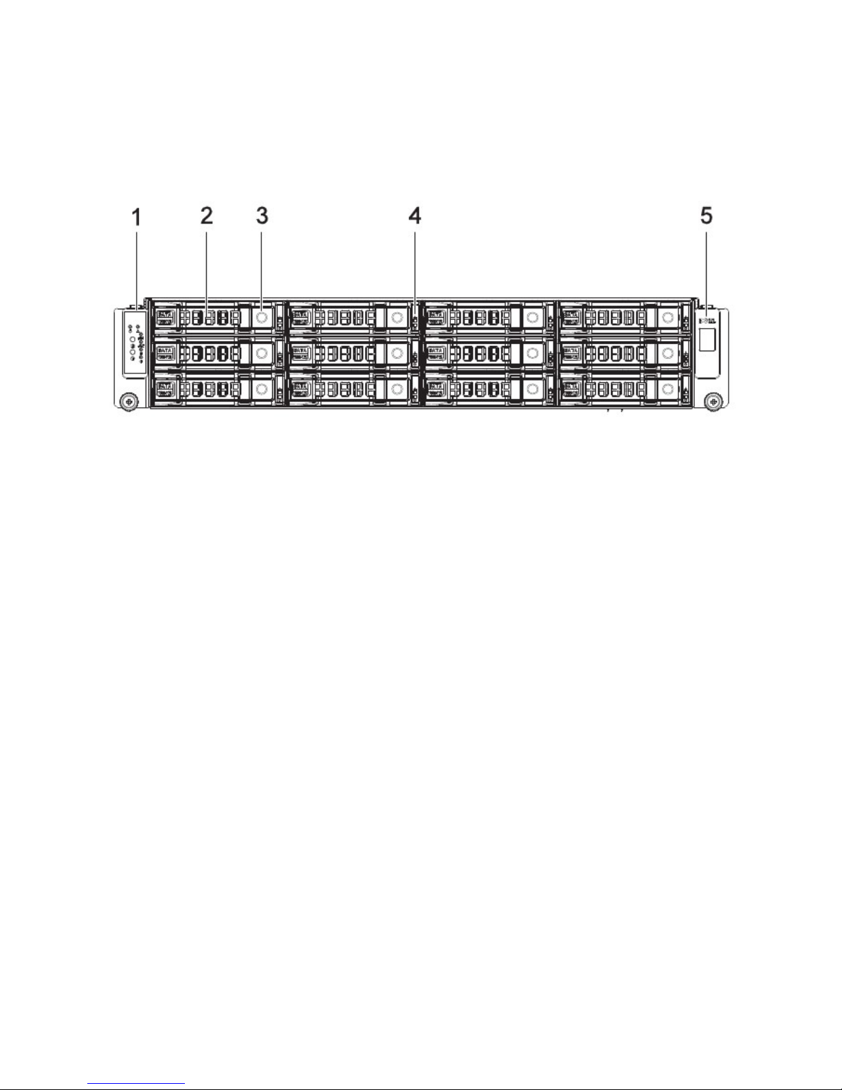
Front View
1.
2.
3.
4.
Front control panel (left)
HDD bay
HDD release lever/ button
HDD status LEDs
See Front Control Panel on page 3.
HDD bay
Use this lever/button to remove the hard drive in HDD bay 1.
Display HDD status:
Active/Present: Green
Fault: Red
5.
Logo panel (right) Right panel
2
Page 11
Chapter 1 — Introduction
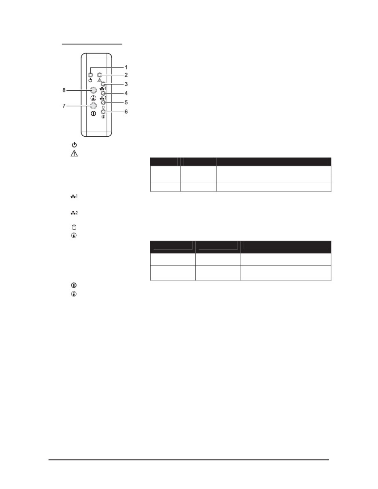
Front Control Panel
1.
2.
Power LED
Status LED
Lights Green when server is powered on.
Displays status/errors and is controlled by BMC
Color
A
mber
A
mber
Condition
Blinking
Off
Occurrence
Non-critical failure: Fan voltage temperature
state.
3.
4.
5.
6.
NIC1 LED
NIC2 LED
HDD active LED
System D LED
Lights green when a connection is made to the NIC1 port, blinks when
NIC1 port is active (access).
Lights green when a connection is made to the NIC2 port, blinks when
NIC2 port is active (access).
Lights Green for hard drive operation.
See table below for behavior.
Color
Blue Off
Blinking
Condition
Occurrence
No identification
Indicate, ID button pressed on chassis
7.
8.
Power button
System D button
Press this button to turn on the QSSC-S99K 2U.
Press to light ID LED.
3
Page 12
Chapter 1 — Introduction
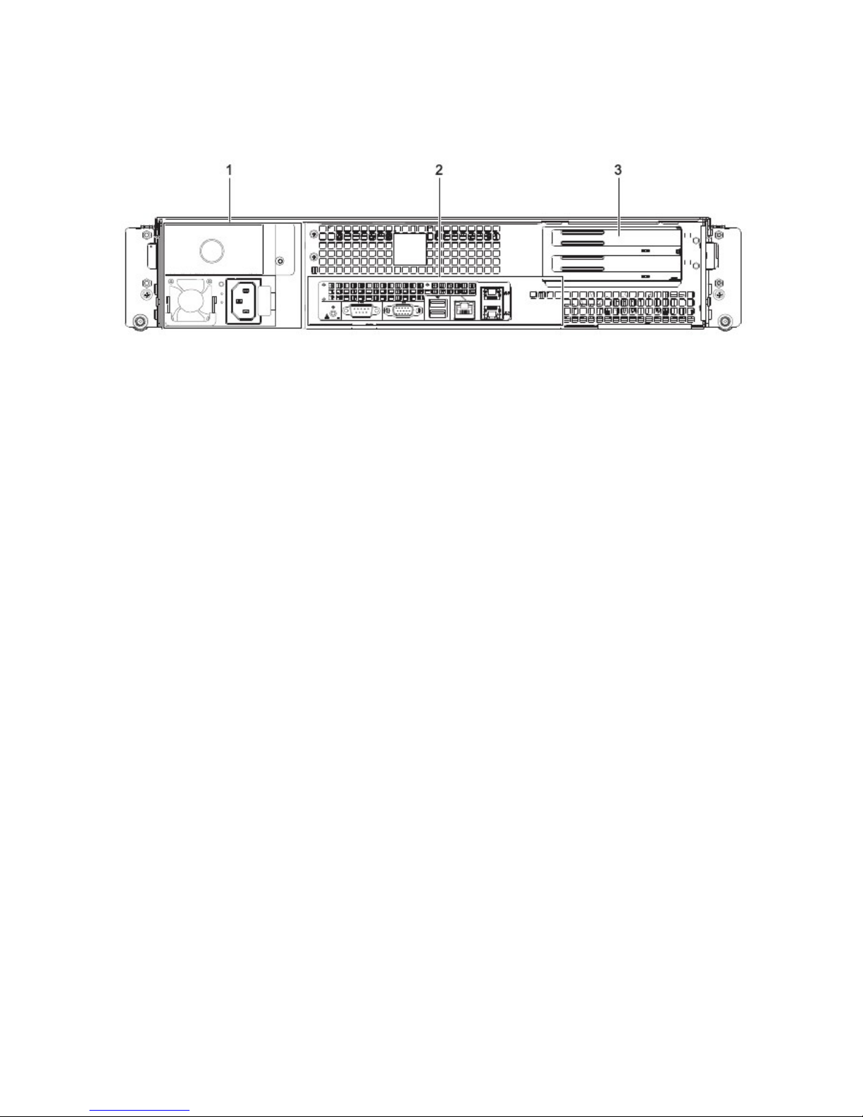
Rear View
1.
2.
3.
Power module
I/O ports
A
dd-on card covers
Connect the power cable to the socket. An optional power module can be installed
for backup power support.
Connect I/O devices to these ports. See QSSC-S99K 2U I/O Ports on page 5.
Remove these covers before installing any PCI-e card.
4
Page 13
Chapter 1 — Introduction
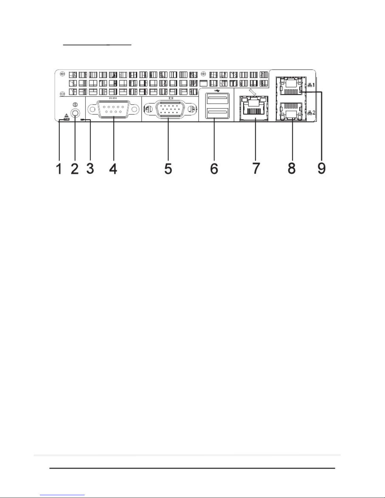
QSSC-S99K 2U I/O Ports
The QSSC-S99K 2U has the following I/O port configuration.
1.
2.
3.
4.
5.
6.
7.
8.
9.
Status LED
ID button
Rear ID LED
Serial port
VGA port
USB ports
Remote monitoring and
management (RMM)
NIC1
NIC2
Behavior is controlled by BMC (see System Controls and LEDs Description on
page 6).
Press to light front and rear ID LEDs (see table below for behavior).
Lights when the system has been selected for identification
Connect serial devices to this port.
Connect a monitor to this port.
Connect USB devices to these two ports.
Connect a RJ-45 jack to this port to link to a 10/100M LAN from AST2000.
Connect a RJ-45 jack to this port to link to a 10/100/1000 Megabit Ethernet
LAN.
Connect a RJ-45 jack to this port to link to a 10/100/1000 Megabit Ethernet
LAN.
5
Page 14
Chapter 1 — Introduction
System Controls and LEDs Description
Front System Controls
RESET
Reset Button
Identification
Button
Power button
Push to restart the system when the system is powered on.
Push to clear the ID LED
Toggles system power. When system is off, push briefly to power on the PSU and
the system. When power is on, push briefly to turn off.
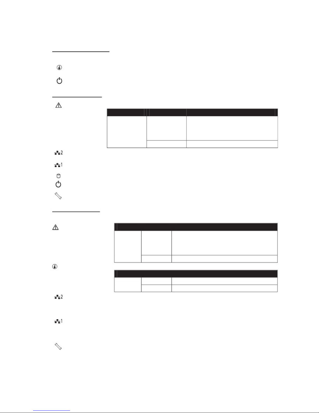
Front System LEDs
Fault LED Displays status/errors and is controlled by BMC.
Color
A
mbe
r
Condition
Blinking
Occurrence
Critical Failure: critical Fan, Voltage, Temperature state
Non-Critical Failure: non-critical Fan, Voltage, Temperature state, CPU Thermal Trip.
Off
NIC2 LED
NIC1 LED
HDD Active LED
Power LED
Service LED
OK
Lights green when a connection is made to the NIC2 port, blinks off when there is
traffic on the NIC2 port.
Lights green when a connection is made to the NIC1 port, blinks off when there is
traffic on the NIC1 port.
Lights for hard drive operation.
Lights when server is powered on. (This LED is inside the button on the 2.5” option)
Lights when the BMC port is on, blinks off when there is traffic on the BMC port.
Rear System LEDs
Status System Status LED Displays status/errors and is controlled by BMC.
Color
A
mbe
r
Condition
Blinking
Occurrence
Critical Failure: critical Fan, Voltage, Temperature
state
Non-Critical Failure: non-critical Fan, Voltage,
Temperature state, CPU Thermal Trip
Off
System ID LED
Color
Blue
LAN2 LED
Condition
Off
On
OK
Occurrence
No Identification requested
Unit selected for identification
Lights when front or rear ID button is pressed.
Link/Act: Lights green when a connection is made to the NIC2 port, blinks off
when there is traffic on the NIC2 port.
Speed: Lights green when speed is 100 Mbits/sec, Lights Amber when speed is
1000Mbits/sec
LAN1 LED
Link/Act: Lights green when a connection is made to the NIC1 port, blinks off
when there is traffic on the NIC1 port.
Speed: Lights green when speed is 100 Mbits/sec, Lights Amber when speed is
1000 Mbits/sec
Service Port
Lights when the BMC port is on, blinks off when there is traffic on the BMC port.
6
Page 15

Chapter 2 — Installing Hardware
Chapter 2
Installing Hardware
Safety Measures
Computer components and electronic circuit boards can be damaged by discharges of static electricity. Working
on computers that are still connected to a power supply can be extremely dangerous. Follow the simple guidelines
below to avoid damage to your computer or injury to yourself.
Always disconnect the computer from the power outlet whenever you are working inside the computer case.
If possible, wear a grounded wrist strap when you are working inside the computer case. Alternatively,
discharge any static electricity by touching the bare metal chassis of the computer case, or the bare metal body
of any other grounded appliance.
Hold electronic circuit boards by the edges only. Do not touch the components on the board unless it is
necessary to do so. Do not flex or stress the circuit board.
Leave all components inside the static-proof packaging until you are ready to use the component for the
installation.
7
Page 16
Chapter 2 — Installing Hardware
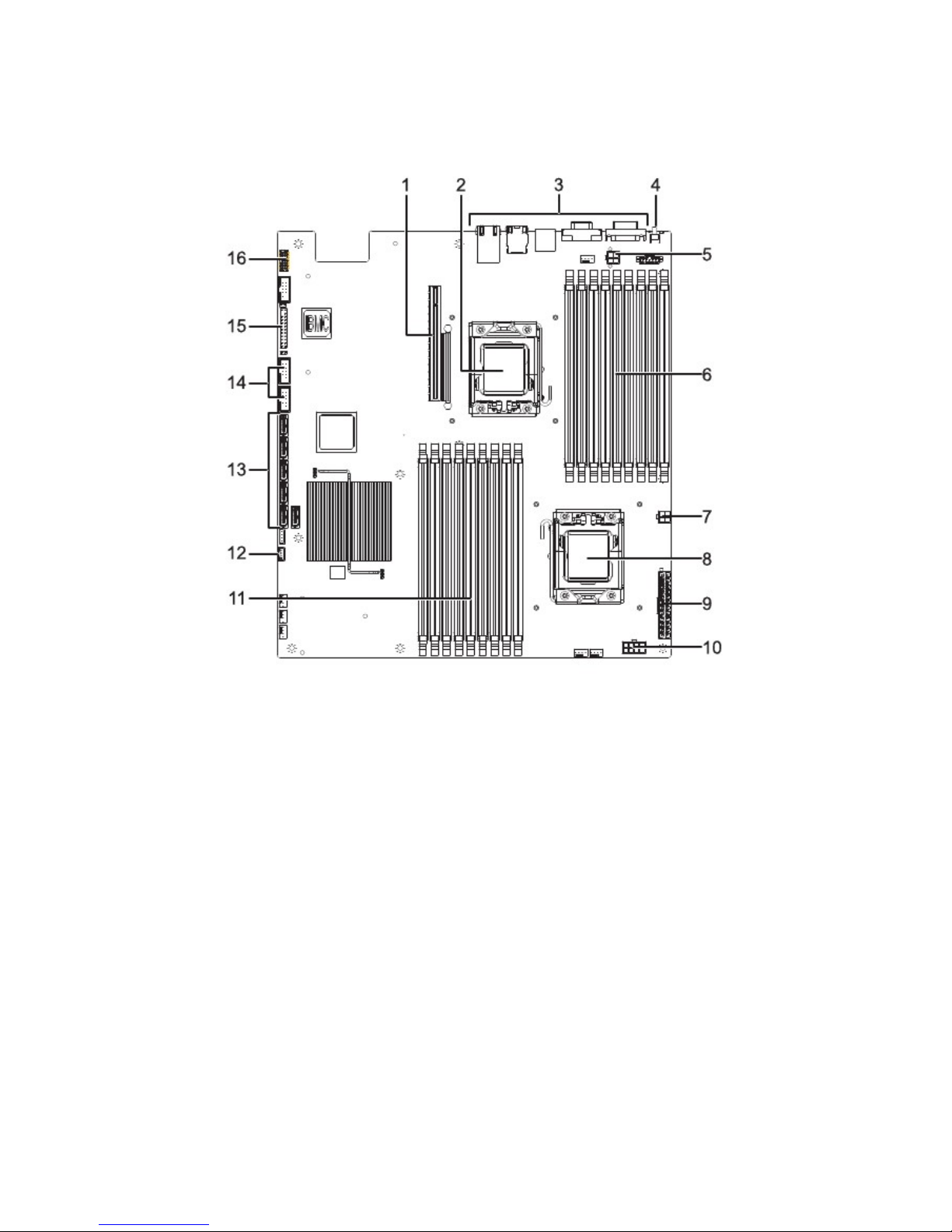
QSSC-S99K 2U Mainboard Components
The following illustration displays the most important mainboard components.
Figure 1 – Mainboard diagram
Item Component
PCI-E Slot for riser card
CPU0 socket
I/O ports (see Rear View on page 4)
ID LED button
CPU0 power connector
DDR3 DIMM slots x9 (CPU0)
CPU0 power connector
CPU1 socket
Mainboard power connector
CPU1 power connector
DDR3 DIMM slots x9 (CPU1)
IPMB connector
SATA II connectors x 6
Front USB connectors x2
Front panel connectors
Port 80
1.
2.
3.
4.
5.
6.
7.
8.
9.
10.
11.
12.
13.
14.
15.
16.
8
Page 17
Chapter 2 — Installing Hardware
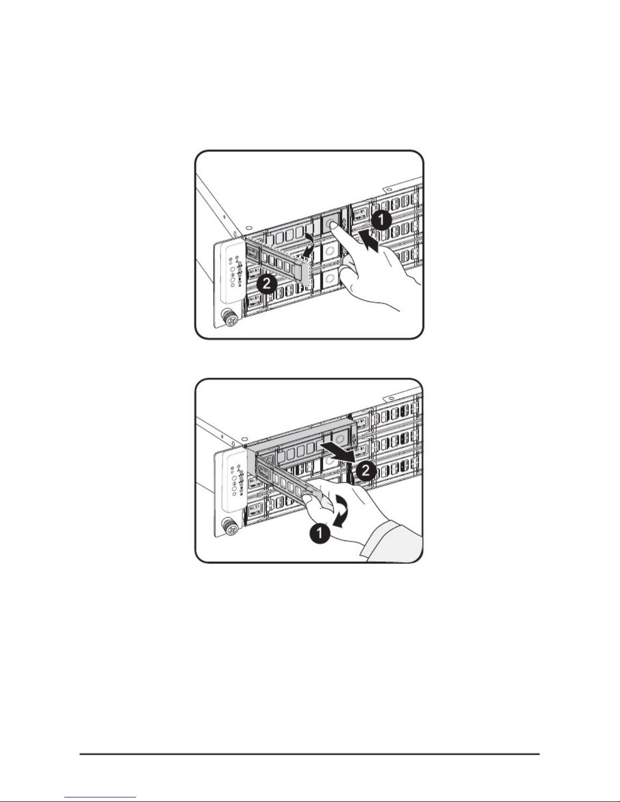
Installing Hard Drives
Follow these instructions to install an HDD:
1.
Push the release button in the direction of the arrow .
The HDD tray-locking handle springs open
.
2.
Open the locking handle and pull to remove the HDD tray .
3.
Place the hard drive on the HDD tray and secure with the four screws. Do not over tighten the
screws.
9
Page 18
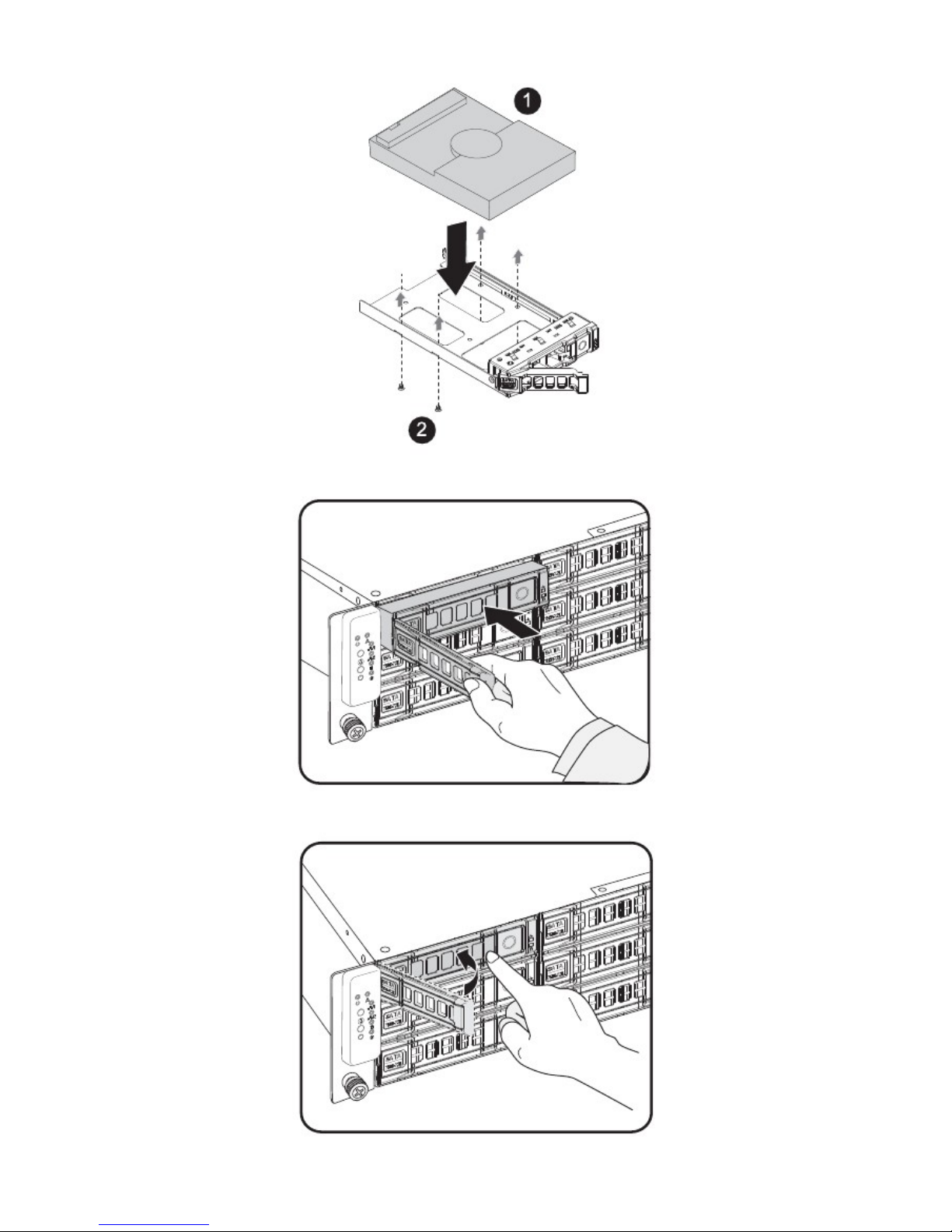
Chapter 2 — Installing Hardware
4. Replace the HDD tray and push firmly until the sits flush in the HDD bay.
5.
Close the locking handle by pushing it in the direction shown until it clicks.
10
Page 19
Chapter 2 — Installing Hardware
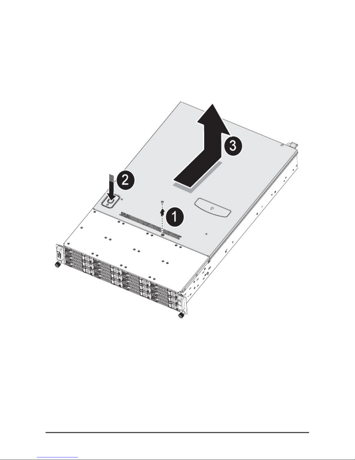
Removing the Chassis Cover
Refer to the following illustrations for instructions on removing the chassis cover:
1.
2.
3.
Remove the securing screw
Press the top cover release button
Slide the cover back and then remove
11
Page 20
Chapter 2 — Installing Hardware
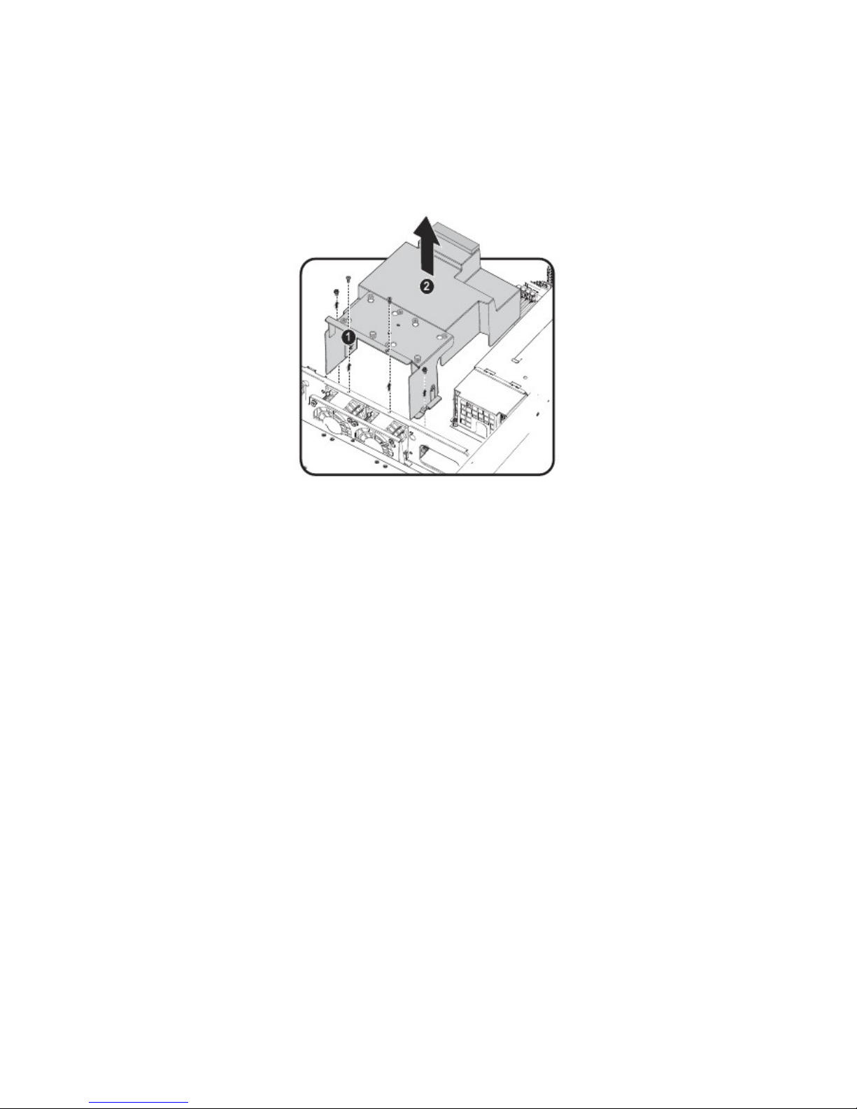
Removing the Fan Duct
Refer to the following instructions to remove the fan duct assembly.
1.
2.
Locate the fan duct cover and remove the four (4) securing screws
Carefully lift up the fan duct cover as shown
12
Page 21
Chapter 2 — Installing Hardware
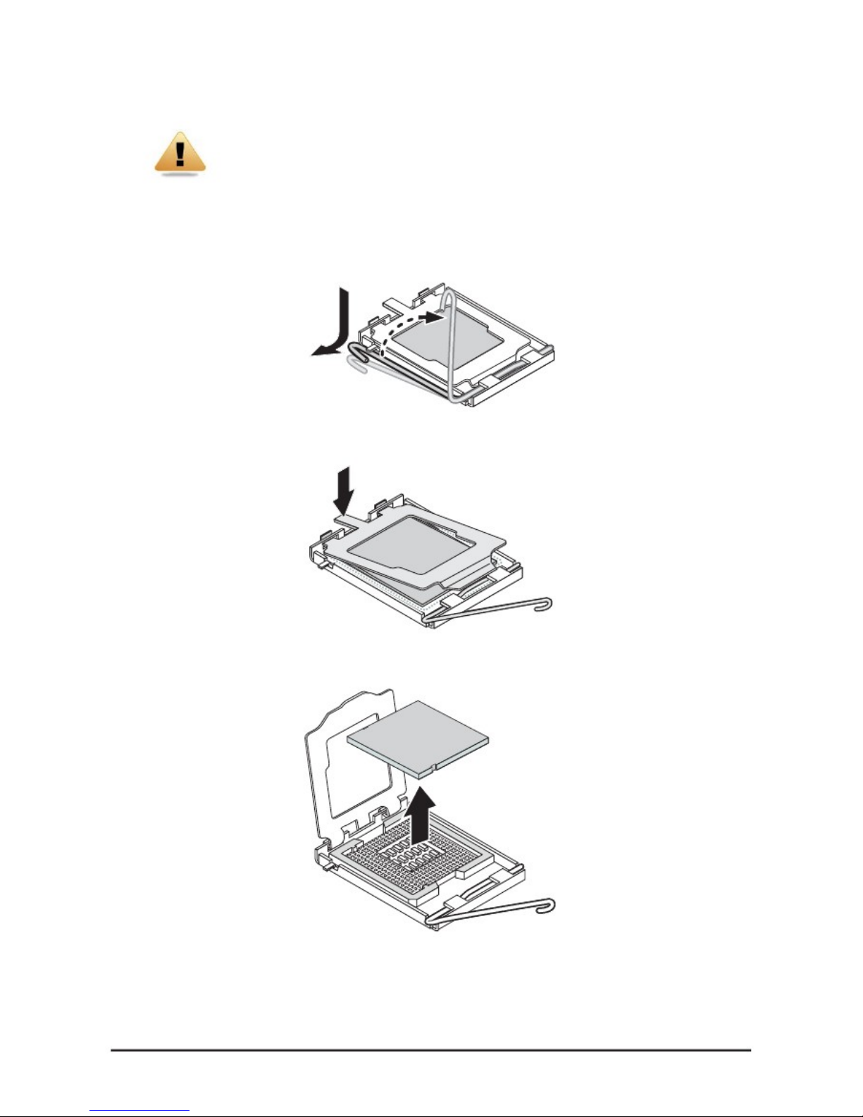
Installing CPUs
WARNING!
In a single CPU configuration, the single processor must be installed in the CPU_1 socket
(see QSSC-S99K 2U Mainboard Components on page 2 for location).
Refer to the following instructions to install CPUs:
Follow these instructions to install the CPU:
1. Pull the locking lever of the CPU socket out and up as shown.
2.
Push down as demonstrated to lift the CPU bracket.
3.
Remove the CPU dust cover by lifting the tab marked Remove.
4.
Locate the pin-1 corner of the CPU (marked by a small triangle) and the pin-1 corner of the socket; note
that the CPU has notches that fit into the socket.
13
Page 22
Chapter 2 — Installing Hardware
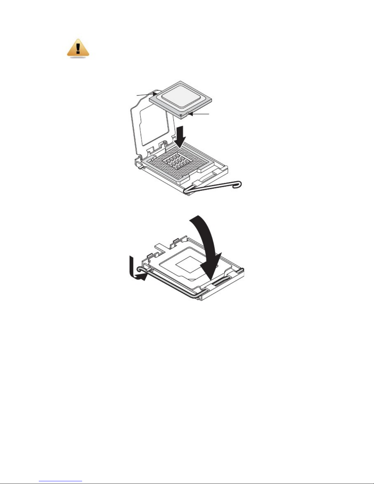
WARNING!
The QSSC-S99K 2U uses LGA 1366 sockets, which are designed for trouble free insertion of the CPU.
A
fter placing a CPU into the socket, press the lever down and lock in place. If you notice any
resistance when inserting the CPU, ensure that it is aligned correctly.
5.
Align the pin-1 corner (▼) and the notches and drop the processor into the socket.
N
otch
N
otch
6.
Replace the CPU bracket and locking lever to lock the processor in place.
7. Repeat steps 1 through 9 for the second CPU.
14
Page 23
Chapter 2 — Installing Hardware
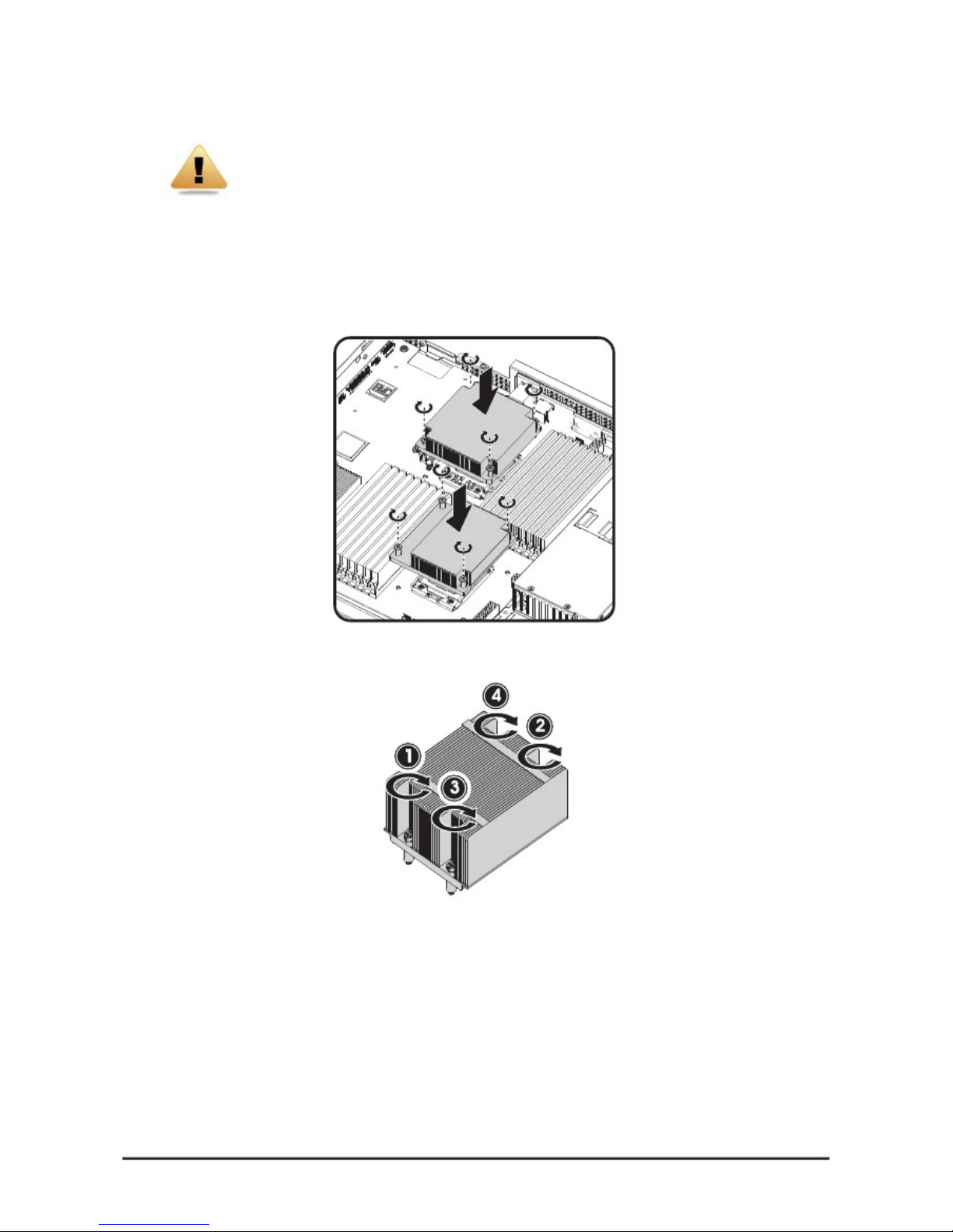
Installing Heat Sinks
WARNING!
If the server board is to be operated with only a single processor, both heat sinks must be
installed to insure proper cooling.
Refer to the following instructions to install heat sinks:
1.
2.
3.
Apply thermal compound evenly on the top of the CPU.
Remove the protective cover from the underside of the heat sink.
Place the heat sink(s) on top of the CPU and tighten the four (per heat sink) captive screws.
4. Tighten the four retaining screws clockwise, in the order shown, to secure the heat sink.
5. Repeat steps 1 through 4 for the second heat sink.
15
Page 24
Chapter 2 — Installing Hardware
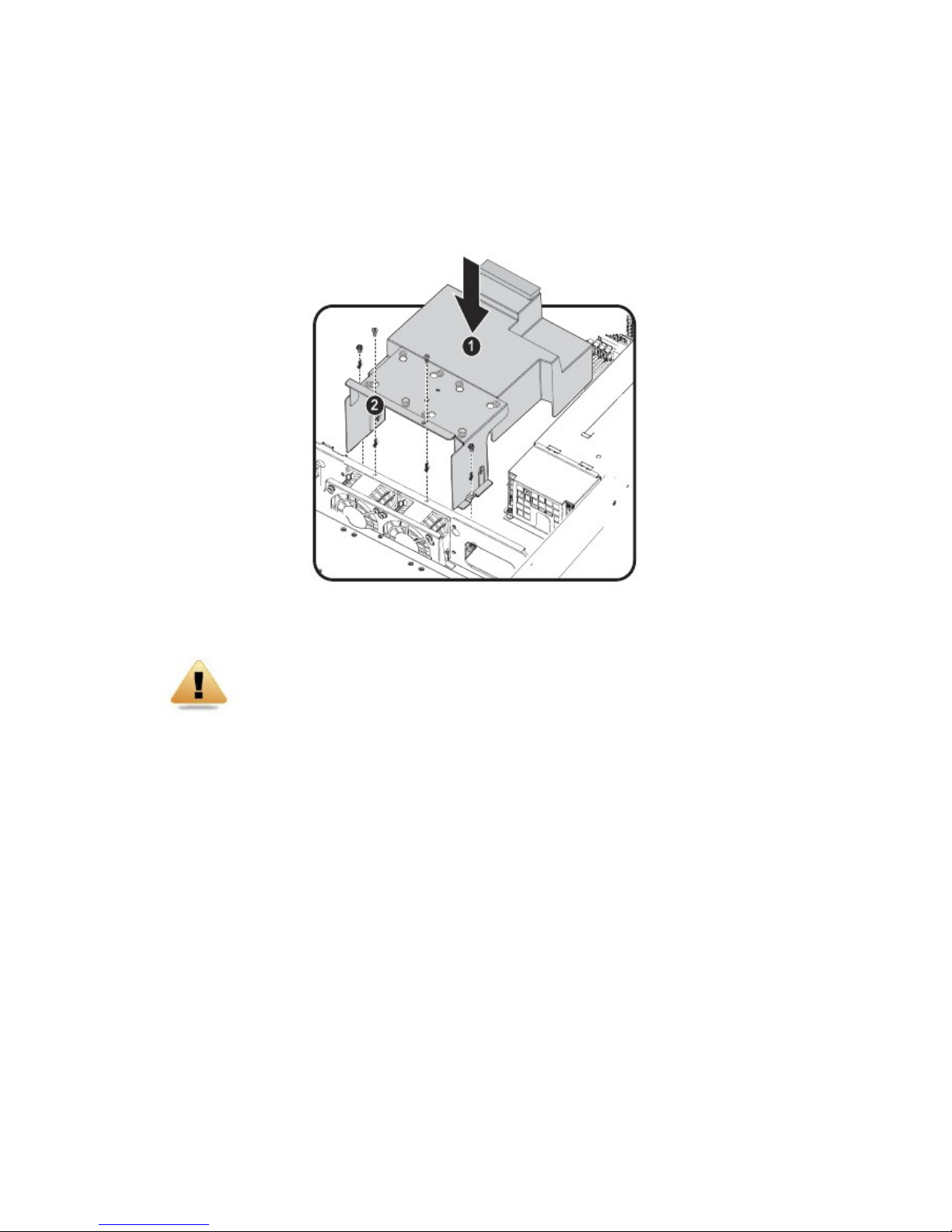
Installing the Fan Duct
Refer to the following instruction to install the fan duct:
1.
2.
Insert the fan duct into place as shown .Ensure it is flush with the fan assembly and the screw holes are
aligned.
Replace the four (4) securing screws .
WARNING!
Fan ducts are situated over and around the DIMM modules. Ensure that all edges are not
lodged inside the memory banks.
16
Page 25
Chapter 2 — Installing Hardware
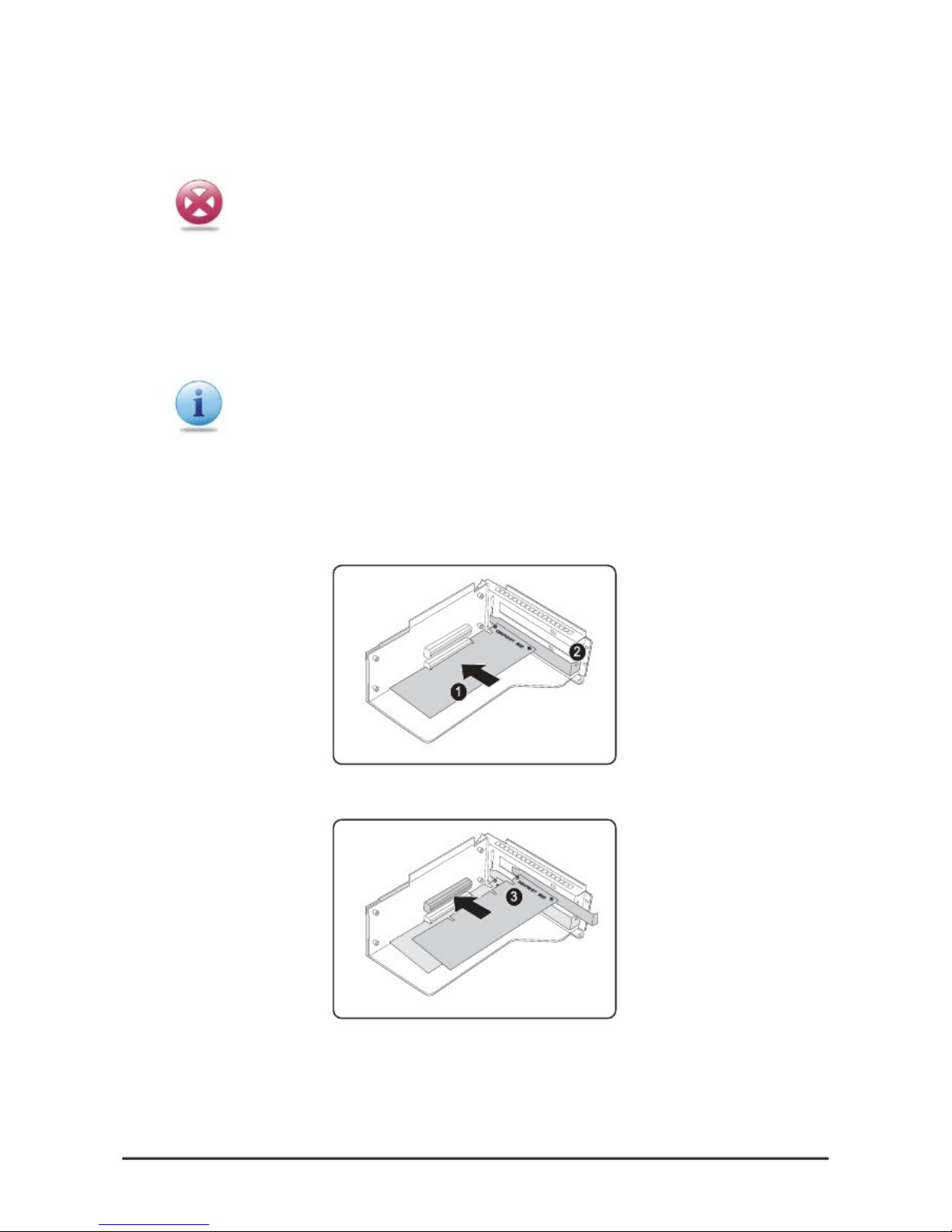
Installing an Expansion Card
CAUTION!
VOLTAGES CAN BE PRESENT WITHIN THE SERVER WHENEVER AN AC POWER
SOURCE IS CONNECTED. THIS VOLTAGE IS PRESENT EVEN WHEN THE MAIN
POWER SWITCH IS IN THE OFF POSITION. ENSURE THAT THE SYSTEM IS POWERED-DOWN AND ALL POWER SOURCES HAVE BEEN DIS-CONNECTED FROM THE
SERVER PRIOR TO INSTALLING A PCI CARD. USE ONLY A S99Q SPECIFIC PCI RISER
CARDS WHEN INSTALLING A PCI CARD.FAILURE TO OBSERVE THESE WARNINGS
COULD RESULT IN PER-SONAL INJURY OR DAMAGE TO EQUIPMENT.
You can install expansion cards on the system's riser board. The riser board plugs into the riser connector on the
system board.
A second PCI card can be installed. Because the lower and upper PCI cards are installed in the same manner, both
use the following procedure.
Note:
The PCI riser assembly does not include a riser card or any cabling as standard. To install a
PCI card, a riser card must be installed. Refer to riser card user manual for installation pro-
cedures.
1.
2.
3.
Remove the riser card. See Replacing the Riser Card on page 19.
Remove the PCI dummy cover on the riser assembly.
Orient the PCI card with the riser guide slot and push in the direction of the arrow until the PCI card sits
in the PCI card connector . Secure the PCI card with the screw as shown .
4.
Repeat Step 3 for a second PCI card.
5. Turn the riser assembly over and insert in the chassis.
See Replacing the Riser Card on page 19.
17
Page 26
Chapter 2 — Installing Hardware
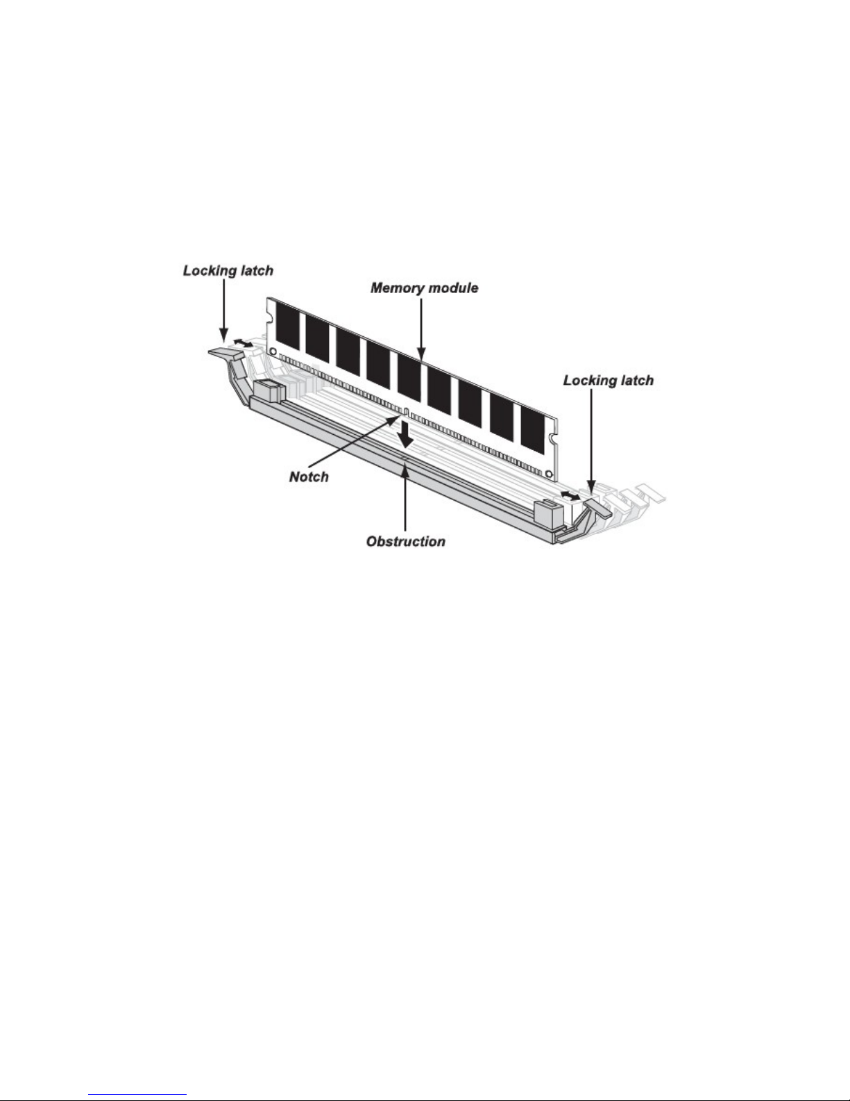
Installing Memory
The mainboard has eighteen DDR3-DIMM slots for the installation of up to twelve un-buffered DIMMs @ DDR3
800/1066/1333 MHz or eighteen registered DIMM memory sockets with ECC. Refer to QSSC-S99K 2U Mainboard Com-
ponents on page 2 for the location of the memory modules.
Refer to the following instructions to install memory modules:
1.
2.
Pull the locking latches of the DIMM slot outwards.
Align the memory module correctly. Note the notch and obstruction in the following illustration.
3. Press the edge connector of the memory module into the slot. Press down firmly so that the locking
latches of the DIMM slot are levered upwards to secure the memory module in place.
18
Page 27

Chapter 2 — Installing Hardware
Supported DIMM Configuration
The following DIMM configurations are supported by the QSSC-S99K 2U server. DIMM slots are numbered 0 to 1 and
designated by 3 channels. Populate DIMM slots starting with slot 0: channel 0. See the following for possible
memory configurations.
DIMM Population Rule
RDIMM population configuration within a channel for three slots per channel.
No. of
DIMMs
POR Speed
DDR3-1333
DDR3-1333
DDR3-1066
DDR3-1333
DDR3-1333
DDR3-1333
DDR3-1333
DDR3-800
DDR3-800
DDR3-800
DDR3-800
DDR3-800
DDR3-800
DDR3-800
DDR3-800
DDR3-800
DDR3-800
DDR3-800
1N or 2N
1N
1N
1N
1N
1N
1N
1N
1N
1N
1N
1N
1N
1N
1N
1N
1N
1N
1N
DIMM 2
Empty
Empty
Empty
Empty
Empty
Empty
Empty
Empty
Empty
Empty
Single-rank
Single-rank
Single-rank
Dual-rank
Single-rank
Dual-rank
Dual-rank
Dual-rank
DIMM 1
Empty
Empty
Empty
Single-rank
Single-rank
Dual-rank
Dual-rank
Single-rank
Dual-rank
Quad-rank
Single-rank
Single-rank
Dual-rank
Single-rank
Dual-rank
Single-rank
Dual-rank
Dual-rank
DIMM 0
Single-rank
Dual-rank
Quad-rank
Single-rank
Dual-rank
Single-rank
Dual-rank
Quad-rank
Quad-rank
Quad-rank
Single-rank
Dual-rank
Single-rank
Single-rank
Dual-rank
Dual-rank
Single-rank
Dual-rank
1.
2.
3.
4.
5.
6.
7.
8.
9.
10.
11.
12.
13.
14.
15.
16.
17.
18.
19
Page 28
Chapter 2 — Installing Hardware
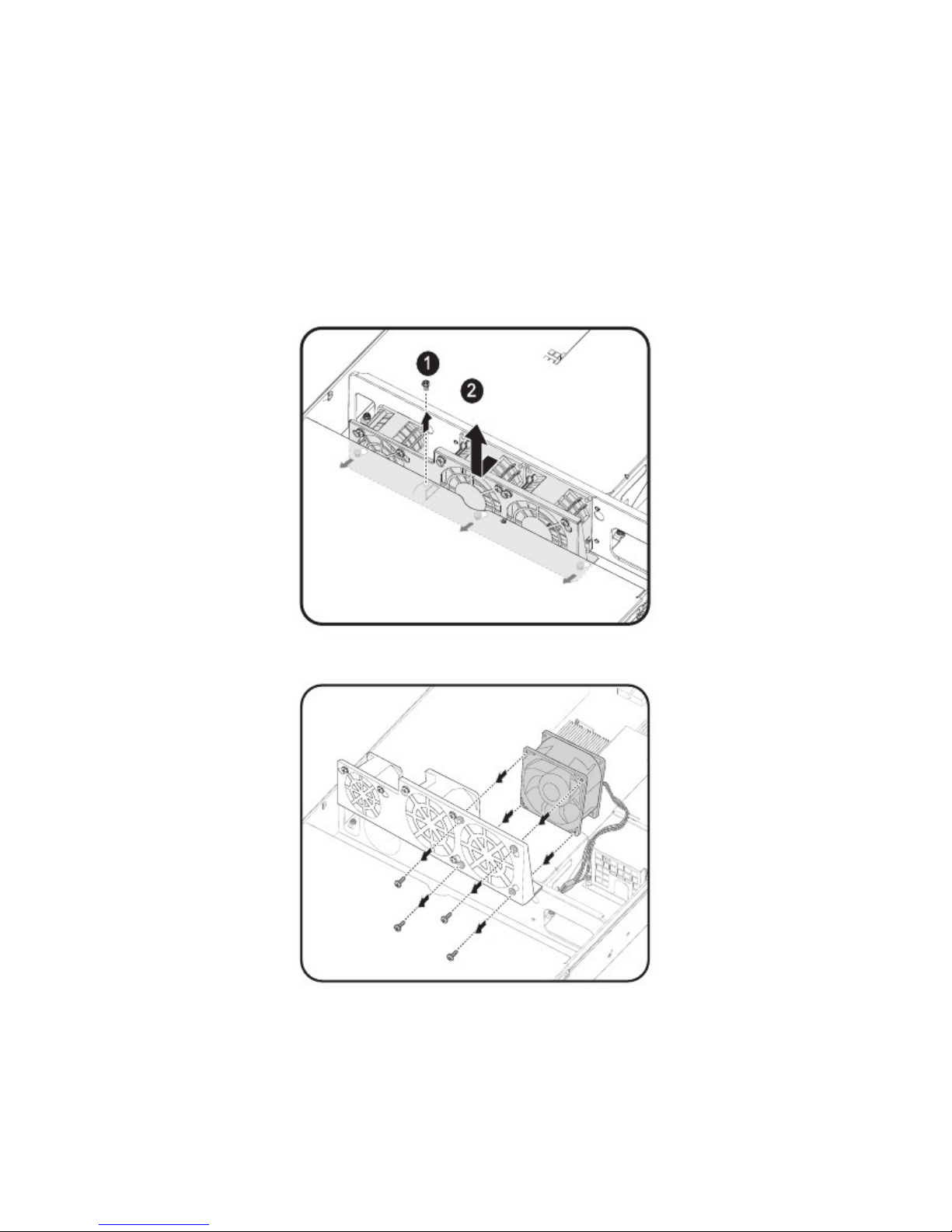
Replacing the Fan Assembly
In case of fan failure, you can quickly replace the fan assembly.
Follow these instructions to replace the fan assembly:
1.
2.
3.
4.
Remove the chassis cover. See Removing the Chassis Cover on page 5.
Disconnect the three (3) power cables from the backplane.
Remove the single securing screw from the chassis as shown.
Slide the assembly to clear the securing pins, and pull up as shown .
5.
Select the fan module to replace and remove the screws from the assembly carrier.
6.
Replace the fan and reverse steps 5 to 1 to connect the fan assembly.
20
Page 29
Chapter 2 — Installing Hardware
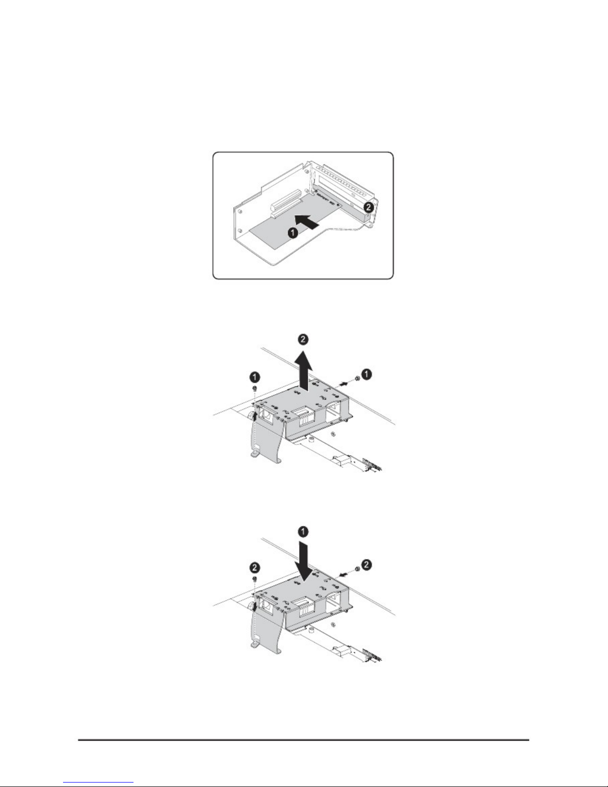
Installing the LSI SAS Raid Card and Battery
To install the LSI SAS Raid Card
1.
2.
Remove the Riser Card from the motherboard as described in Replacing the Riser Card on page 19.
Insert the LSI SAS Raid Card into the riser card as shown.
3.
4.
Locate the battery carrier and remove the two (2) securing screws .
Lift the battery carrier up to remove .
5.
6.
Turn the battery carrier over and affix the battery in place.
Replace the battery and carrier assembly , and secure in place with the two (2) screws .
7. Connect the battery leads into the indicated location on the LSI SAS Raid Card.
21
Page 30

Chapter 2 — Installing Hardware
8. Replace the Riser assembly. See Replacing the Riser Card on page 19.
Note:
The PCI riser assembly does not include a riser card or any cabling as standard. To install a
PCI card, a riser card must be installed. Refer to riser card user manual for installation pro-
cedures.
22
Page 31

Chapter 2 — Installing Hardware
Installing a Redundant Power Supply Unit
Follow the instructions as provided in the following guide to install a redundant power supply unit (PSU).
Note:
You can also install an optional backup power supply. Contact your dealer for details.
1.
2.
Remove the single securing screw from the PSU bracket .
Remove the blank bracket .
3. Insert the new power supply unit it locks in place.
23
Page 32

Chapter 2 — Installing Hardware
Replacing a Power Supply Unit
In case of a power supply failure, you can quickly replace the power supply unit (PSU).
Note:
You can also install an optional backup power supply. Contact your dealer for details.
Follow these instructions to install the redundant power supply:
1.
2.
3.
Lift the PSU handle to grasp it.
Push the locking lever in to release the PSU .
Pull the PSU by the handle to remove .
4. Insert the new power supply unit it locks in place.
24
Page 33

Chapter 2 — Installing Hardware
Replacing the Riser Card
Refer to the following illustrations for instructions on replacing the riser card:
1.
2.
Remove the top cover. See Removing the Chassis Cover on page 5.
Firmly grasp the riser assembly and lift up and away. See the following image.
3.
4.
5.
Turn the assembly over and place on a clean static mat.
Remove the securing screw (1) and slide the riser card as shown (2).
Pull out the riser card as shown in the following figure.
6.
To replace the riser card, reverse steps 5 to 1.
25
Page 34

Chapter 2 — Installing Hardware
Replacing the Expander Backplane
WARNING!
A
lways disconnect power cables before installing or removing any components from the
computer, including the expander backplane.
Disconnect the power cable before installing or removing any cables from the backplane.
Make sure that the backplane is securely installed to prevent damage to the system.
To remove the backplane board, perform the following steps:
1.
2.
3.
4.
5.
6.
7.
8.
9.
Remove the chassis cover. See Removing the Chassis Cover on page 5.
Remove the Fan Duct. See Removing the Fan Duct on page 6.
Remove the Fan Assembly. See Replacing the Fan Assembly on page 14.
Locate and disconnect the fan and the power cables from the backplane board.
Remove the two securing screws from the backplane board.
Grasp the backplane and gently remove the board from the chassis.
Place the new board in the chassis. Ensure that the board is right side up and the twelve hard-disk driver
connectors face outward.
Secure the board with the two screws.
Connect the fan and power cables.
10. Replace the Fan Assembly. See Replacing the Fan Assembly on page 14.
11. Replace the Fan Duct. See Removing the Fan Duct on page 6.
12. Replace the Chassis Cover. See Replacing the Chassis Cover on page 22.
26
Page 35

Chapter 2 — Installing Hardware
Replacing the Motherboard
In order to remove the motherboard, you need to disconnect all connections between the motherboard and compo-
nents in the case and any cables that are simply in the way.
Important!
When removing any component, wear a properly grounded static strap to prevent static discharge.
Follow these instructions to replace the motherboard:
1.
2.
3.
4.
5.
6.
7.
8.
9.
Unplug the power supply.
Remove the chassis cover. See Removing the Chassis Cover on page 5.
Remove all installed memory. See Installing Memory on page 12.
Remove the PCI riser card assembly. See Replacing the Riser Card on page 19.
Remove the heat sinks from the chassis. See Installing Heat Sinks on page 9.
Remove the CPU(s) from the chassis. See Installing CPUs on page 7.
Disconnect the power, IPMB, SATA, front panel, and mainboard cable connectors from the motherboard.
See QSSC-S99K 2U Mainboard Components on page 2.
Remove the ten (10) screws securing the mainboard in place.
Lift the mainboard out of the chassis in the direction of the arrow, front edge first, to clear the I/O ports.
10. When replacing the mainboard, align holes A and B to position the mainboard correctly in the chassis.
11. Replace the ten (10) screws to secure the motherboard in place.
12. Reconnect the power, IPMB, SATA, front panel, and mainboard connectors to the mainboard. See QSSC-S99K
2U
Mainboard Components on page 2.
13. Replace all removed components.
14. Replace the chassis cover. See Replacing the Chassis Cover on page 22.
27
Page 36

Chapter 2 — Installing Hardware
Replacing the Chassis Cover
Refer to the following instructions to replace the chassis cover:
1.
2.
Replace cover and slide in the direction shown (1).
Replace the securing screw (2).
28
Page 37

BIOS
BIOS System Support
BIOS Features
AMI Core 08.00.16
OEM Special Functions
Boot-Device Sequence Selection
OEM Logo Screen
Shadow RAM BIOS feature
Boot Block Feature
SMBIOS 2.5
ACPI 2.0
PXE 2.1
IPMI 2.0
4MB Flash EPROM
AC Power Loss handling
BIOS POST
At the system boot, BIOS should perform initial diagnostic test of hardware (CPU, Memory, PCI …etc). If "BIOS
Detected Error", BIOS stops the system. In any case, display an error message with POST Code. Some of the event will
be logged to BMC (e.g. CMOS checksum error, Memory ECC error, PCI error…), in any POST stop case, BMC will
timeout with a POST code event log.
BIOS stratagem is to stop the POST and display error message only when the error is detect by BIOS during POST. The
error detected by BMC or MMB during POST will handle and react by BMC or MMB, these errors are unaware for
BIOS, so BIOS will not stop the POST and not display error message to screen. For example CPU temp is monitored by
BMC to log the event, but no reaction by BMC, the CPU will do TM2 (Thermal Monitor 2) to reduce the CPU’s speed
and the temp, the worst case is, if CPU’s temp go more higher, the CPU’s Thermtrip output pin will assert to ICH10 and
make a system shut down by H/W (not by BMC). CPU’s voltage is also monitored by BMC with event log,
If error is detected, POST Code is displayed on Screen.
PCI Sub-System Sub-Device ID
SVID: 152Dh
SDID: 8981h
Hotkeys
The BIOS provides the hot keys during POST or BIOS Setup as following:
Chapter 3 — BIOS
Chapter 3
29
Page 38

Key or Key Sequence Function Availability
F2
Enter BIOS Setup During POST
F7
Discard Changes In BIOS Setup
F9
Load Optimal (e.g. CMOS) Defaults In BIOS Setup
F10
Save Settings and Exit In BIOS Setup
F11
BBS POPUP During POST
F12
PXE Boot During POST
ESC
Skip Memory Test During POST
Tab
Skip Logo During POST
Ctrl + HOME
BIOS Recovery During Boot Block
Note:
When populate an add-on card, please don’t press the add-on card option ROM control key and “F2” (Enter
BIOS setup) at the same POST. Because some add on card may need to be modified first and the information
will be show in bios setup menu at next boot (for example: SAS Raid card HDD information).
LEDs
Power LED will be turned on when system is in power on state.
Power LED Status Function description
OFF Shutdown
ON Power ON
Blink at 50% Duty Cycle Sleep/Suspend
Boot Device Sequence Selection
S99K 2U BIOS support BBS Ver.1.01.
Eventlog
S99K 2U BIOS will log POST errors and ECC/PCI/IOH/QPI errors, and eventlog can be seen from BIOS Setup. BMC
will record other system events, like FAN speed, Thermal…etc, the user can get the information through BIOS Setup and
AST2050 UI-WEB.
ECC Eventlog
S99K 2U will log two ECC events.
PCIE Eventlog
S99K 2U will log three kinds of error, correctable, uncorrectable and fatal error, for PCI-Express.
Chapter 3 — BIOS
30
Page 39

System Management BIOS (SMBIOS)
System Management BIOS Ver. 2.5 is supported.
ACPI BIOS
S99K 2U BIOS supports ACPI BIOS with system state S0, S1, S4, S5.
RAID
S99K 2U platform support RAID0, RAID1, and RAID0+1.
Console redirection
S99K 2U BIOS supports console redirection to a serial port.
If serial port based headless server support is provided by the system, the system must provide support for redirection of
all BIOS driven console I/O to the serial port .The driver for the serial console must be capable of supporting the
capabilities documented in Extensions to the ANSI Terminal Definition.
Configuring Special Keys
Console redirection used ANSI terminal emulation, which is limited to basic ASCII characters. There are no function
keys, arrow keys, or control keys in this character set. However, S99K 2U BIOS software requires the use of function
keys and control keys for ordinary functions. You can emulate a function key or control key by using a special key
sequence, call on escape sequence, to represent a specific key.
For console redirection, an escape sequence starts with an escape character. This character can be entered in a number of
different ways, depending on the requirements of your terminal emulation software. For example, 0x1b, ^[, and <Esc> all
refer to the same escape character.
Following table list the escaped sequence that must be sent to represent a special key or command.
Structure Name and Type Supported
BIOS INFORMATION (TYPE 00) Yes
SYSTEM INFORMATION (TYPE 01) Yes
BASE BOARD INFORMATION (TYPE 02) Yes
SYSTEM ENCLOSURE OR CHASSIS (TYPE 03) Yes
PROCESSOR INFORMATION (TYPE 04) Yes
CACHE INFORMATION (TYPE 07) Yes
PORT CONNECTOR INFORMATION (TYPE 08) Yes
SYSTEM SLOTS (TYPE 09) Yes
ONBOARD DEVICES INFORMATION (TYPE 10) Yes
OEM STRINGS (TYPE 11) Yes
BIOS LANGUAGE INFORMATION (TYPE 13) Yes
PHYSICAL MEMORY ARRAY (TYPE 16) Yes
MEMORY DEVICE (TYPE 17) Yes
SYSTEM BOOT INFORMATION(TYPE 32) Yes
IPMI DEVICE INFORMATION (TYPE 38) Yes
End of Table (Type 127) Yes
Chapter 3 — BIOS
31
Page 40

VT100 Supported Escape Sequences
UTF8/ANSI Supported Escape Sequences
Note: Reset key function need to press “Ctrl”, “Shift” and “–“ at the same time.
Processor Configuration
For S99K 2U, only identical processors should be installed in system. S99K 2U is 2-socket boards which may have 1 or 2
processors installed. When a single processor is installed, it must be installed into CPU Socket 0, and only DIMM sockets
on memory channels corresponding to CPU Socket 0 may be used.
Chapter 3 — BIOS
Key Escape Sequence
Up <ESC> [<Shift>a
Down <ESC> [<Shift>b
Right <ESC> [<Shift>c
Left <ESC> [<Shift>d
Home <ESC> [<Shift>h
End <ESC> [<Shift>k
F1 <ESC><Shift>op
F2 <ESC><Shift>oq
F3 <ESC><Shift>or
F4 <ESC><Shift>os
Key Escape Sequence
F1 <ESC>1
F2 <ESC>2
F3 <ESC>3
F4 <ESC>4
F5 <ESC>5
F6 <ESC>6
F7 <ESC>7
F8 <ESC>8
F9 <ESC>9
F10 <ESC>0
F11 <ESC>!
F12 <ESC>@
Home <ESC>h
End <ESC>k
Ins <ESC>+
Del <ESC>-
Alt <ESC>^A
Ctrl <ESC>^C
Page Up <ESC>?
Page Down <ESC>/
Reset <Ctrl> <Shift> -
32
Page 41

Memory Configuration
DIMM population
For three slots per channel configuration, the Tylersburg-EP platform require s DIMMs within a channel to be populated
starting with the DIMMs farthest from the processor in a “fill-farthest” approach. In addition, when populating a
quad-rank DIMM with a Single- or Dual-rank DIMM in the same channel, the Quad-rank DIMM must be populated
farthest from the processor. Note that Quad-rank DIMMs are not allowed in three slots populated configurations. All
allowed DIMM population configurations for three slots per channel are shown in below tables.
Chapter 3 — BIOS
33
Page 42

Memory RAS
1. Independent Channel Mode
Channels can be populated in any order in Independent Channel Mode. All three channels may be populated in any order
and have no matching requirements. All channels must run at the same interface frequency, but individual channels may
run at different DIMM timings (RAS latency, CAS latency, etc.).
2. Mirrored Channel Mode
In Mirrored Channel Mode, the memory contents are mirrored between Channel 0 and Channel 1. As a result of the
mirroring, the total physical memory available to the system is half of what is populated. Mirrored Channel Mode
requires that Channel 0 and Channel 1 must be populated identically. DIMM slot populations within a channel do not
have to be identical but the same DIMM slot location across Channel 0 and Channel 1 must be populated the same.
Channel 2 is unused in Mirrored Channel Mode.
3. Mirrored Channel Mode
In Lockstep Channel Mode, each memory access is a 128-bit data access that spans
Channel 0 and Channel 1. This is done to support SDDC for DRAM devices with 8-bit wide data ports. The same address
is used on both channels such that an address error on any channel is detectable by bad ECC. Lockstep Channel mode is
the only RAS mode that supports x8 SDDC. Lockstep Channel Mode requires that Channel 0 and Channel 1 must be
populated identically. That is, each DIMM in one channel must have a corresponding DIMM of identical organization
such as number of ranks, banks, rows, and/or columns. DIMMs may be of different speed grades, but the Integrated
Memory Controller will be configured to operate all DIMMs according to the slowest parameters present. DIMM slot
populations within a channel do not have to be identical but the same DIMM slot location across Channel 0 and Channel
1 must be populated the same. Channel 2 is unused in Lockstep Channel Mode.
34
Chapter 3 — BIOS
Page 43

LV DIMM support
35
Chapter 3 — BIOS
Page 44

Setup Function
Summary Screen
Summary Screen is shown prior to booting Operating System. Example:
BIOS Setup Options at Boot
The user will be able to initiate BIOS SETUP by pressing the respective keys.
<F2> Enter the BIOS Setup
Access Level
The Access Level property controls who has access to the control (supervisor, user, etc.). The following table summarizes
the effect of Access Level on a control.
Chapter 3 — BIOS Chapter 3 — BIOS Chapter 3 — BIOS
36
System Configuration, AMI BIOS Version 08.00.16
Main Processor(s) : Inter® CPU @2.40GHz
Math Processor : Built-In Base Memory Size : 640KB
Extd Memory Size : 2040MB Serial Port(s) : 3F8, 2F8
Display Type : VGA/EGA BIOS Built Date : 11/24/09
ACPI v2.0 : Enabled BMC Interface : KCS
Page 45

SETUP submenu: Main
NOTE 1: *N (N is 1, 2, 3 ….) lists the possible selection items for each SETUP ITEM.
NOTE 2: The default value for each SETUP ITEM is marked with bold and shadow.
SETUP submenu: Advance
37
Chapter 3 — BIOS
Control Group User Access Level
System Date Access Level 2
System Time Access Level 2
BIOS Setup Utility
Main Advanced Boot Server Security Exit
Use [ENTER], [TAB]
Or [SHIFT-TAB] to
Select a field.
Use [+] or [-] to
Configure system Time.
← Select Screen
↑↓ Select Item
-+ Change Field
Tab Select Field
F1 General Help
F10 Save and Exit
ESC Exit
System Overview
----------------------------------------------------
AMIBIOS
Version : S99_2A01
Build Date : 07/30/10
Product : QSSC
Processor
Genuine Intel® CPU 000 @ 2.40GHz
Speed : 2400MHz
Counte : 2
System Memory
Size : 2048MB
System Date [Fri/30/2010]
System Time [09:40:55]
v02.66 © Copyright 1985-2009, American Megatrends, Inc.
Main Advanced Boot Server Security Exit
Configure CPU.
← Select Screen
↑↓ Select Item
Enter Go to Sub Screen
F1 General Help
F10 Save and Exit
ESC Exit
BIOS Setup Utility
Advanced Settings
----------------------------------------------------
WARMING: Setting wrong values in below section
may cause system to malfunction.
► CPU Configuration
► Memory Configuration
► IDE Configuration*1
► SuperIO Configuration
► USB Configuration
► PCI Configuration
v02.66 © Copyright 1985-2009, American Megatrends, Inc.
Page 46

Control Group User Access Level
CPU Configuration Access Level 3
Memory Configuration Access Level 3
IDE Configuration Access Level 3
SuperIO Configuration Access Level 3
USB Configuration Access Level 3
PCI Configuration Access Level 3
*1: Only for SATA SKU.
CPU Configuration
*1: Disabled/Enabled (Only for CPUs that support this feature.)
*2: Disabled/Enabled (Only for CPUs that support this feature.)
*3: All/1/2
*4: Disabled/ACPI C2/ACPI C3
*5: Disabled/Enabled (NUMA for SLES 11 )
*6: Compute/IO
Control Group User Access Level
Hardware Prefetcher Access Level 1
Adjacent Cache Line Prefetch Access Level 1
L1 Data Prefectcher Access Level 1
Data Reuse Optimization Access Level 1
QPI Bandwidth Priority Access Level 1
Max CPUID Value Limit Access Level 1
Chapter 3 — BIOS
38
Advanced
Disabled for WindowsXP
← Select Screen
↑↓ Select Item
-+ Change Option
F1 General Help
F10 Save and Exit
ESC Exit
Configure advanced CPU settings
----------------------------------------------------
Intel® Xeon® CPU X5560 @ 2.80GHz
CPUID : 206C0
Frequency : 2.40GHz
BCLK Speed : 133MHz
Cache L1 : 384KB
Cache L2 : 1536 KB
Cache L3 : 12288 KB
Ratio Status : Unlocked (Min:12, Max:18)
Ratio Actual Value:18
Hardware Prefetcher [Enabled] *2
Adjacent Cache Line Prefetch [Enabled] *2
L1 Data Prefectcher [Enabled] *2
Data Reuse Optimization [Enabled] *2
QPI Bandwidth Priority [Compute] *6
Max CPUID Value Limit [Disabled] *1
Intel® Virtualization Tech [Enabled] *2
Execute-Disable Bit Capability [Enabled] *2
Intel® HT Technology [Enabled] *2
Active Processor Cores [All] *3
Intel® SpeedStep(tm) tech [Enabled] *2
Intel® Turbo mode tech [Enabled] *2
Intel® C-STATE tech [Enabled] *2
C3 State [Disabled] *4
C6 State [Enabled] *2
NUMA Support [Disabled] *5
BIOS Setup Utility
v02.66 © Copyright 1985-2009, American Megatrends, Inc.
Page 47

Intel® Virtualization Tech Access Level 1
Execute-Disable Bit Capability Access Level 1
Intel® HT Technology Access Level 1
Active Processor Cores Access Level 1
Intel® SpeedStep™ tech Access Level 1
Intel® TurboMode tech Access Level 1
Intel® C-STATE tech Access Level 1
C3 State Access Level 1
C6 State Access Level 1
NUMA Support Access Level 1
S99K 2U supports Nehalem-EP and Westmere-EP processors.
For detail description about hardware support, please refer to HW SPEC.
Memory Configuration
*1: Auto/ 800 Mhz/ 1066 Mhz
*2: Independent/Channel Mirroring/Lockstep
*3: Disable/Enabled
Control Group User Access Level
Memory Frequency Access Level 1
Memory Mode Access Level 1
Throttling - Closed Loop Access Level 1
Throttling - Open Loop Access Level 1
Chapter 3 — BIOS
39
Advanced
BIOS Setup Utility
pppppppOptionspppppp
Forces a DDR3
Frequency slower than
the common tCK
detected via SPD
← Select Screen
↑↓ Select Item
-+ Change Option
F1 General Help
F10 Save and Exit
ESC Exit
System Memory Settings
----------------------------------------------------
Current Memeory Frequency 1066MHz
Memory Frequency [Auto]*1
Memory Mode [Independent]*2
Throttling – Closed Loop [Enabled]*3
Throttling – Open Loop [Enabled]*3
v02.66 © Copyright 1985-2009, American Megatrends, Inc.
Page 48

IDE Configuration
*1: Disabled/Compatible/Enhanced
*2: IDE/RAID/AHCI
*3: Disabled/Enabled
*4: 0/5/10/15/20/25/30/35
Control Group User Access Level
SATA Configuration Access Level 1
Configure SATA#1 as Access Level 1
SATA Port0 Access Level 3
SATA Port1 Access Level 3
SATA Port2 Access Level 3
SATA Port3 Access Level 3
SATA Port4 Access Level 3
SATA Port5 Access Level 3
Hard Disk Write Protect Access Level 1
IDE Detect Time Out (Sec) Access Level 1
HDD Security Erase Support Access Level 1
Chapter 3 — BIOS
40
Advanced
BIOS Setup Utility
pppppppOptionspppppp
Disabled
Compatible
Enhanced
← Select Screen
↑↓ Select Item
-+ Change Option
F1 General Help
F10 Save and Exit
ESC Exit
IDE Configuration
----------------------------------------------------
SATA Configuration [Enhanced]*1
Configure SATA#1 as [IDE]*2
► SATA Port0 : [Hard Disk]
► SATA Port1 : [Not Detected]
► SATA Port2 : [Not Detected]
► SATA Port3 : [Not Detected]
► SATA Port4 : [Not Detected]
► SATA Port5 : [Not Detected]
Hard Disk Write Protect [Disabled]*3
IDE Detect Time Out (Sec) [35]*4
HDD Security Erase Support [Disabled]*3
Advanced
BIOS Setup Utility
Disabled: Disables LBA
Mode.
Auto: Enables LBA Mode if
the device supports it and
the device is not already
formatted with LBA Mode
disabled.
← Select Screen
↑↓ Select Item
-+ Change Option
F1 General Help
F10 Save and Exit
ESC Exit
SATA Port1
----------------------------------------------------
Device : Hard Disk
Vendor : ST320410A
Size : 20.0GB
LBA Mode : Supported
Block Mode : 16Sectors
PIO Mode : 4
Async DMA : MultiWord DMA-2
Ultra DMA : Ultra DMA-2
S.M.A.R.T : Supported
----------------------------------------------------
Type [Auto]*1
LBA/Large Mode [Auto]*2
Block (Multi-Sector Transfer) [Auto]*2
PIO Mode [Auto]*3
DMA Mode [Auto]*4
S.M.A.R.T. [Auto]*5
32Bit Data Transfer [Enabled]*6
v02.66 © Copyright 1985-2009, American Megatrends, Inc.
v02.66 © Copyright 1985-2009, American Megatrends, Inc.
Page 49

*1: Not Installed/Auto/CD/DVD/ARMD
*2: Disabled/Auto
*3: Auto/0/1/2/3/4
*4: Auto/SWDMA0/SWDMA1/SWDMA2/MWDMA0/MWDMA1/MWDMA2
/UDMA0/UDMA1/UDMA2/UDMA3/UDMA4/UDMA5/UDMA6
*5: Auto/Disabled/Enabled
*6: Disabled/Enabled
Control Group User Access Level
Type Access Level 1
LBA/Large Mode Access Level 1
Block (Multi-Sector Transfer) Mode Access Level 1
PIO Mode Access Level 1
DMA Mode Access Level 1
S.M.A.R.T. Access Level 1
32Bit Data Transfer Access Level 1
SuperIO Configuration
*1: Disabled/[3F8/IRQ4]/[3E8/IRQ4]/[2E8/IRQ3]
*2: Disabled/[2F8/IRQ3]/[3E8/IRQ4]/[2E8/IRQ3]
Control Group User Access Level
Serial Port1 Address Access Level 1
Serial Port2 Address Access Level 1
Chapter 3 — BIOS
41
Advanced
BIOS Setup Utility
A
llows BIOS to Select
Serial Port1 Base
Addresses.
← Select Screen
↑↓ Select Item
-+ Change Option
F1 General Help
F10 Save and Exit
ESC Exit
Configure Win627DHG Super IO Chipset
---------------------------------------------------Serial Port1 Address [3F8/IRQ4]*1
Serial Port2 Address [2F8/IRQ3]*2
v02.66 © Copyright 1985-2009, American Megatrends, Inc.
Page 50

USB Configuration
*1: Disabled/Auto
Control Group User Access Level
Legacy USB Support Access Level 1
USB Mass Storage Device Configuration Access Level 3
*1:10 Sec / 20 Sec / 30 Sec / 40 Sec
*2: Auto / Floppy / Forced FDD / Hard Disk / CDROM
Control Group User Access Level
USB Mass Storage Reset Delay Access Level 1
Emulation Type Access Level 1
42
Chapter 3 — BIOS
A
uto option disables
Legacy support if no
USB devices are
connected.
← Select Screen
↑↓ Select Item
-+ Change Option
F1 General Help
F10 Save and Exit
ESC Exit
USB Configuration
----------------------------------------------------
USB Devices Enabled :
3 Keyboard, 3 Mice, 1 Drive
Legacy USB Support [Auto]*1
USB 2.0 Controller [Enabled]
► USB Mass Storage Device Configuration
Advanced
BIOS Setup Utility
v02.66 © Copyright 1985-2009, American Megatrends, Inc.
Advanced
BIOS Setup Utility
Number of seconds POST
waits for the USB mass
storage Devices after start
Unit command.
← Select Screen
↑↓ Select Item
-+ Change Option
F1 General Help
F10 Save and Exit
ESC Exit
USB Mass Stroage Device Configuration
----------------------------------------------------
USB Mass Stroage Reset Delay [20 Sec] *1
Device#1 USB Flash Disk
Emulation Type [Auto]*2
v02.66 © Copyright 1985-2009, American Megatrends, Inc.
Page 51

PCI Configuration
*1: Disabled/Enable with PXE/Enable without PXE
*2: Slow-Mode/Full-Speed
*3: Auto/4.800GT/5.866GT/6.400GT
*4: Disabled/Enabled
*5: Disabled/Enabled
*6: Auto/128 Bytes/256 Bytes
NOTE: If “iSCSI Remote Boot” be enabled, then both NIC1 and NIC2 will not be displayed.
Control Group User Access Level
Maximum Payload Size Access Level 2
iSCSI Remote Boot Access Level 1
NIC1 – KAWELA Access Level 1
NIC2 - KAWELA Access Level 1
PCI-E SLOT Option ROM Access Level 2
PCI-E Connector Option ROM Access Level 2
QPI Links Speed Access Level 1
QPI Frequency Access Level 1
QPI L0s and L1 Access Level 1
Crystal Beach / DMA Access Level 1
Intel VT-d Access Level 1
SR-IOV Supported Access Level 1
Active State Power Management Access Level 2
ME Support Access Level 1
Chapter 3 — BIOS
43
Advanced
BIOS Setup Utility
pppppppOptionspppppp
Disabled
Enable with PXE
Enabled without PXE
iSCSI Remote Boot.
← Select Screen
↑↓ Select Item
-+ Change Option
F1 General Help
F10 Save and Exit
ESC Exit
PCI Configuration
----------------------------------------------------
Maximum Payload Size [Auto]*6
iSCSI Remote Boot [Disabled] *4
NIC1 - KAWELA [Enable with PXE]*1
NIC2 - KAWELA [Enable with PXE]*1
PCI-E SLOT Option Rom [Enabled] *5
PCI-E Connector Option Rom [Enabled] *5
NIC1 Mac Address [00-23-8B-64-8E-EC-CD]
NIC2 Mac Address [00-23-8B-64-8E-EC-CE]
Current QPI Frequency 6.400GT
QPI Links Speed [Full-Speed]*2
QPI Frequency [Auto]*3
QPI L0s and L1 [Enabled] *5
Crystal Beach/DMA [Disabled]*4
Intel VT-d [Disabled]*4
SR-IOV Supported [Disabled]*4
Active State Power-Management [Disabled]*4
ME Support [Enabled] *5
v02.66 © Copyright 1985-2009, American Megatrends, Inc.
Page 52

SETUP submenu: Boot
Boot Settings Configuration
44
Control Group User Access Level
Boot Settings Configuration Access Level 3
Boot Device Priority Access Level 3
Hard Disk Drives Access Level 3
CD/DVD Device Access Level 3
Network Device Access Level 3
USB Drives Access Level 3
Chapter 3 — BIOS
Main Advanced Boot Server Security Exit
Configure Settings during
System Boots.
← Select Screen
↑↓ Select Item
-+ Change Option
F1 General Help
F10 Save and Exit
ESC Exit
Boot Settings
----------------------------------------------------
► Boot Settings Configuration
► Boot Device Priority
► Hard Disk Drives
► CD/DVD Device
► Network Device
► USB Drives
BIOS Setup Utility
v02.66 © Copyright 1985-2009, American Megatrends, Inc.
Boot
A
llow BIOS to skip certain
tests while booting. This
will decrease the time
needed to boot the system.
← Select Screen
↑↓ Select Item
-+ Change Option
F1 General Help
F10 Save and Exit
ESC Exit
Boot Settings Configuration
----------------------------------------------------
Quick Boot [Enabled]*1
Quiet Boot [Disabled]*2
AddOn ROM Display Mode [Force BIOS]*3
Bootup Num-Lock [On]*4
Wait For ‘F1’ If Error [Disabled]*2 *5
Hit ‘F2’ Message Display [Enabled]*1
BIOS Setup Utility
v02.66 © Copyright 1985-2009, American Megatrends, Inc.
Page 53

*1: Disabled/Enabled
*2: Disabled/Enabled
*3: Force BIOS/Keep Current
*4: Off/On
*5: Only for POST error event
Boot Device Priority
Control Group User Access Level
1st Boot Device Access Level 1
2nd Boot Device Access Level 1
Control Group User Access Level
Quick Boot Access Level 2
Quiet Boot Access Level 2
AddOn ROM Display Mode Access Level 1
Bootup Num-Lock Access Level 1
Wait For 'F1' If Error Access Level 1
Hit 'F2' Message Display Access Level 1
Chapter 3 — BIOS
45
Specifies the boot
sequence from the
available devices.
A device enclosed in
parenthesis has been
disabled in the
corresponding type menu.
← Select Screen
↑↓ Select Item
-+ Change Option
F1 General Help
F10 Save and Exit
ESC Exit
Boot Device Priority
----------------------------------------------------
1st Boot Device [USB:USB Flash Disk]
2nd Boot Device [Network: IBA GB Slo]
Boot
BIOS Setup Utility
v02.66 © Copyright 1985-2009, American Megatrends, Inc.
Page 54

SETUP submenu: Server
*1: Disabled/Enabled
*2: Disabled/Enabled
*3: Power Off/Power On/Last State
*4: Disabled/Correctable/Uncorrectable/Fatal
Control Group User Access Level
Set BMC LAN Configuration Access Level 3
Remote Access Configuration Access Level 3
Restore on AC Power Loss Access Level 1
View BMC System Event Log Access Level 3
Clear BMC System Event Log Access Level 1
Event Logging Access Level 1
ECC Event Logging Access Level 1
PCI Error Logging Access Level 1
QPI Error Logging Access Level 1
IOH Internal Error Logging Access Level 1
NMI on Error Access Level 1
46
Chapter 3 — BIOS
Main Advanced Boot Server Security Exit
Configure Remote Access.
←→ Select Screen
↑↓ Select Item
Enter Go to Sub Screen
F1 General Help
F10 Save and Exit
ESC Exit
IPMI Configuration
----------------------------------------------------
Status Of BMC Working
IPMI Specification Version 2.0
BMC Firmware Version 00 00.01
► Set BMC LAN Configuration
► Remote Access Configuration
Restore on AC Power Loss [Power On]*3
Event Control Interface
----------------------------------------------------
►View BMC System Event Log
Clear BMC System Event Log
Event Logging [Enabled] *1
ECC Event Logging [Enabled] *1
PCI Error Logging [Enabled] *1
QPI Error Logging [Enabled] *1
IOH Internal Error Logging [Enabled] *1
NMI on Error [Fatal]*4
BIOS Setup Utility
v02.66 © Copyright 1985-2009, American Megatrends, Inc.
Page 55

Set BMC LAN Configuration
*1: Dedicated -NIC/ Shared-NIC
*2: Disabled/ Enabled
*3: Input By User
*4: Don’t set Lan in BIOS menu and BMC web at the same time
Control Group User Access Level
BMC LAN Port Configuration Access Level 1
DHCP Enabled Access Level 1
IP Address Access Level 1
Subnet Mask Access Level 1
GateWay Address Access Level 1
Chapter 3 — BIOS
47
Server
Select BMC LAN port
to dedicated-NIC or
shared-NIC
← Select Screen
↑↓ Select Item
-+ Change Option
F1 General Help
F10 Save and Exit
ESC Exit
Lan Configuration
----------------------------------------------------
Channel Number [01]
Channel Number Status : Status is OK
BMC LAN Port Configuration [Shared-NIC]*1
DHCP Enabled [Disabled]*2
IP Address [192.168.001.002]*3
Subnet Mask [255.255.255.000]*3
GateWay Address [192.168.001.001]*3
Current Mac address in BMC: 00.00.64.3D.30.78
BIOS Setup Utility
v02.66 © Copyright 1985-2009, American Megatrends, Inc.
Page 56

Remote Access Configuration
*1: Disabled/Enabled
*2: COM1/COM2
*3: 115200 8,n,1/57600 8,n,1/38400 8,n,1/19200 8,n,1/09600 8,n,1
*4: None/Hardware/Software
*5: Disabled/Enabled
*6: ANSI/VT100/VT-UTF8
Limitation: When populate serial device, the remote access function must be disabled.
Control Group User Access Level
Remote Access Access Level 2
Serial port number Access Level 2
Serial Port Mode Access Level 2
Flow Control Access Level 2
Redirection After BIOS POST Access Level 2
Terminal Type Access Level 2
View BMC System Event Log
Chapter 3 — BIOS
48
Select Remote Access
type.
← Select Screen
↑↓ Select Item
-+ Change Option
F1 General Help
F10 Save and Exit
ESC Exit
Configure Remote Access type and parameters
----------------------------------------------------
Remote Access [Enabled]*1
Serial port number [COM1]*2
Current SOL Baud Rate 115200 bps
Serial Port Mode [115200 8,n,1]*3
Flow Control [None]*4
Redirection After BIOS POST [Enabled]*5
Terminal Type [ANSI]*6
Server
BIOS Setup Utility
v02.66 © Copyright 1985-2009, American Megatrends, Inc.
Use +/- to traverse
The event log.
← Select Screen
↑↓ Select Item
-+ Change Option
F1 General Help
F10 Save and Exit
ESC Exit
Total Number Of Entries: 84
----------------------------------------------------
SEL Entry Number [1]
SEL Record ID: 0001
SEL Record Type 02(System Event)
Event Timestamp: 48s from SEL init
Generator ID: 0020
Event Message Format Ver: 04 (IPMI ver 2.0)
Event Sensor Type 14 (Button)
Event Sensor Number: D3
Event Dir Type: 6F
Event Data: 00 00 00
- Power Button pressed
- N/A
- N/A
Server
BIOS Setup Utility
v02.66 © Copyright 1985-2009, American Megatrends, Inc.
Page 57

SETUP submenu: Security
*1: No Access/View Only/Limited/Full Access
*2: Setup/Always
Control Group User Access Level
Change Supervisor Password Access Level 0
User Access Level Access Level 0
Change User Password Access Level 1
Clear User Password Access Level 1
Password Check Access Level 1
SETUP submenu: Exit
Chapter 3 — BIOS
49
Main Advanced Boot Server Security Exit
Install or Change the
Password
← Select Screen
↑↓ Select Item
-+ Change Option
F1 General Help
F10 Save and Exit
ESC Exit
Security Settings
----------------------------------------------------
Supervisor Password : Not Installed
User Password : Not Installed
Change Supervisor Password
User Access Level [Full Access] *1
Change User Password
Clear User Password
Password Check [Setup] *2
Main Advanced Boot Server Security Exit
Exit system setup
after saving the
changes.
F10 key can be used
for this operation.
← Select Screen
↑↓ Select Item
-+ Change Option
F1 General Help
F10 Save and Exit
ESC Exit
Exit Options
----------------------------------------------------
Save Changes and Exit
Discard Changes and Exit
Discard Changes
Load Optimal Defaults
BIOS Setup Utility
v02.66 © Copyright 1985-2009, American Megatrends, Inc.
BIOS Setup Utility
v02.66 © Copyright 1985-2009, American Megatrends, Inc.
Page 58

ControlGroup UserAccessLevel
SaveChangesandExit AccessLevel2
DiscardChangesandExit AccessLevel3
DiscardChanges AccessLevel3
LoadOptimalDefaults AccessLevel1
Save Changes and Exit
Highlight this item and press Enter to save any changes that you have made in the Setup utility and exit the Setup utility.
When the Save Settings and Exit dialog box appears, select [OK] item to save the changes and exit, or press [Cancel] to
return to the setup main menu. [F10] key can be used for this operation.
Discard Changes and Exit
Highlight this item and press Enter to discard any changes that you have made in the Setup utility and exit the Setup utility.
When the Exit Discarding Changes dialog box appears, press [OK] to discard changes and exit, or press [Cancel] to return to
the setup main menu. [ESC] key can be used for this operation.
Discard Changes
If you highlight this item and press Enter, a dialog box asks if you want to discard the settings changes for all the items in the
Setup utility. Select the [OK] item to indicate Yes, and then press Enter to bypass the optimal settings changes.
Load Optimal Defaults
If you highlight this item and press Enter, a dialog box asks if you want to install optimal settings for all the items in the
Setup utility. Select the [OK] item to indicate Yes, and then press Enter to install the optimal settings. [F9] key can be used
for this operation.
Chapter 3 — BIOS
50
Page 59

ACPI BIOS Specification
System States
The S99K 2U hardware supports these ACPI states as followings. The S99K 2U could wake up from S0, S1 and S4.
G0, System in working mode
While the system is in the S0 state, it is in the system working state. The behavior of this state is defined as:
The processors are in the C0, C1, C2, or C3 states. The processor complex context is maintained and instructions are
executed as defined by any of these processor states.
Dynamic RAM context is maintain ed and is read/write by the processors.
Devices states are individually managed by the operating software and can be in any device state (D0, D1, D2 or D3).
Power Resources are in a state compatible with the current device states.
Transition into the S0 state from some system sleeping state is automatic, and by virtue that instructions are being executed
the OS assumes the system to be in the S0 state.
G1, System in Suspend to Memory
While the system is in this state, it is in the system S4 sleeping state. The state is logically lower than the S1 state and is
assumed to conserve more power. The behavior of this state is defined as follows:
The processors are not executing instructions. The processor complex context is not maintained.
Dynamic RAM context is maintain ed.
Power Resources are in a state compatible with the system S4 state. All Power Resources that supply a System Level
reference of S0 or S1 are in the OFF state.
Device states are compatible with the current Power Resource states. Only devices that solely reference Power
Resource that are in the On state for a given device state can be in that device state.
Devices that are enabled to wake the system and that can do so from their current device state can initiate a hardware
event that transitions the system state to S0.
Resume events are: Power button.
G1, System in Suspend to Disk mode (S4 is done by OS)
While the system is in this state, it is in the system S4 sleeping state. The state is logically lower than the S1 state and is
assumed to conserve more power. The behavior of this state is defined as follows:
The processors are not executing instructions. The processor complex context is not maintained.
Dynamic RAM context is not maintained.
Power Resources are in a state compatible with the system S4 state. All Power Resources that supply a System Level
reference of S0 or S1 are in the OFF state.
Device states are compatible with the current Power Resource states. In other words, all devices are in the D3 state
when the system state is S4.
Devices that are enabled to wake the system and that can do so from their D3 device state can initiate a hardware event
which transitions the system state to S0. This transition causes the processor to begin execution at its boot location.
Resume events are: Power button.
Chapter 3 — BIOS
51
Page 60

G2, System Soft Off
Power is removed from most of system components, Suspend Well logic in ICH10, SIO.
G3, Mechanical off
Kinds of computer state that system entered and only left mechanical means. It is implied by the entry of this off state
through a mechanical means that the no electrical current is running through the circuitry and it can be worked on without
damaging the hardware or endangering the service personnel. No hardware context is retained. Except for the real time clock,
power consumption is zero. No power source is attached to the system (AC or battery). Pushing the Power button will be no
function in state at all.
Resume events are: Power Button
Query System Address Map
INT 15H, E820H - Query System Address Map
This call can be used in real mode only.
This call returns a memory map of the entire installed RAM, and of physical memory ranges reserved by the BIOS. Making
successive calls to this API, each returning one run of physical address information, returns the address map. Each run has a
type that dictates how this run of physical address range is to be treated by the operating system.
If the information returned from E820 in some way differs from INT-15 88 or INT-15 E801, the information returned from
E820 supersedes the information returned from INT-15 88 or INT-15 E801. This replacement allows the BIOS to return any
information that it requires from INT-15 88 or INT-15 E801 for compatibility reasons. For compatibility reasons, if E820
returns any AddressRangeACPI or AddressRangeNVS memory ranges below 16Mb, the INT-15 88 and INT-15 E801
functions must return the top of memory below the AddressRangeACPI and AddressRangeNVS memory ranges.
Input
EAX Function Code E820h
EBX Continuation
Contains the continuation value to get the next run of physical memory. This is
the value returned by a previous call to this routine. If this is the first call, EBX
must contain zero.
ES:DI Buffer Pointer Pointer to an Address Range Descriptor structure that the BIOS fills in.
ECX Buffer Size
The length in bytes of the structure passed to the BIOS. The BIOS fills in the
number of bytes of the structure indicated in the ECX register, maximum, or
whatever amount of the structure the BIOS implements. The minimum size that
must be supported by both the BIOS and the caller is 20 bytes. Future
implementations might extend this structure.
EDX Signature
'SMAP' – Used by the BIOS to verify the caller is requesting the system map
information to be returned in ES:DI.
Chapter 3 — BIOS
52
Page 61

Output
CF Carry Flag Non-Carry – Indicates No Error
EAX Signature 'SMAP' – Signature to verify correct BIOS revision.
ES:DI Buffer Pointer Returned Address Range Descriptor pointer. Same value as on input.
ECX Buffer Size
Number of bytes returned by the BIOS in the address range descriptor. The
minimum size structure returned by the BIOS is 20 bytes.
EBX Continuation
Contains the continuation value to get the next address descriptor. The actual
significance of the continuation value is up to the discretion of the BIOS. The
caller must pass the continuation value unchanged as input to the next iteration of
the E820 call in order to get the next Address Range Descriptor. A return value of
zero means that this is the last descriptor.
NOTE: The BIOS can also indicate that the last descriptor has already been
returned during previous iterations by returning a carry. The caller will ignore any
other information returned by the BIOS when the carry flag is set.
Address Range Descriptor Structure
Offset in Bytes Name Description
0 BaseAddrLow Low 32 Bits of Base Address
4 BaseAddrHigh High 32 Bits of Base Address
8 LengthLow Low 32 Bits of Length in Bytes
12 LengthHigh High 32 Bits of Length in Bytes
16 Type Address type of this range
The BaseAddrLow and BaseAddrHigh together are the 64-bit base address of this range. The base address is the physical
address of the start of the range being specified.
The LengthLow and LengthHigh together are the 64-bit length of this range. The length is the physical contiguous length in
bytes of a range being specified.
The Type field describes the usage of the described address range as defined in the following table.
Address Ranges in the Type Field
Valu
e
Mnemonic Description
1 AddressRangeMemory This run is available RAM usable by the operating system.
2 AddressRangeReserved
This run of addresses is in use or reserved by the system and must not be
used by the operating system.
3 AddressRangeACPI
ACPI Reclaim Memory. This run is available RAM usable by the operating
system after it reads the ACPI tables.
4 AddressRangeNVS
ACPI NVS Memory. This run of addresses is in use or reserve by the
system and must not be used by the operating system. This range is
required to be saved and restored across an NVS sleep.
Othe
r
Undefined
Undefined - Reserved for future use. Any range of this type must be treated
by the OS as if the type returned was AddressRangeReserved.
Chapter 3 — BIOS
53
Page 62

The BIOS can use the AddressRangeReserved address range type to block out various addresses as not suitable for use by a
programmable device. Some of the reasons a BIOS would do this are:
The address range contains system ROM.
The address range contains RAM in use by the ROM.
The address range is in use by a memory-mapped system device.
The address range is, for whatever reason, unsuitable for a standard device to use as a device memory space.
Chapter 3 — BIOS
54
Page 63

BIOS and BMC Communication
There is one interface for BMC and BIOS communication, KCS. BIOS uses IPMI standard and OEM commands, and
follows their message format as well as protocol to communicate with BMC. BIOS must send/get complete Request and
Response data to/from BMC; otherwise, it may make a mess of BMC. For example, BMC will response “Get Device ID”
with 12-16 bytes data. Even if BIOS just needs data byte 4 and 5, it must read all response bytes data rather than 5
bytes.( Refer KCS interface section 9)
Overview
Purpose and Scope
This document specifies the server BIOS design guideline to support BMC (Base-board Management Controller) firmware as
well as SMS (server management software). The BMC is a micro-controller support IPMI (Intelligent Platform Management
Interface) for server management. BMC and its related circuit may be built on server motherboard or on a daughter board.
BMC firmware needs server BIOS providing some system information and reaction for server management. For SMS,
SMBIOS is a major interface that SMS can get system information and status.
KCS
Keyboard Controller Style (KCS) interface follows Intel 8742 bit definitions and operation. Data is transferred across the
KCS interface using a per-byte handshake.
System I/O Ports and Registers
To avoid SMS KCS transfer being interrupted by BIOS SMI handler, BIOS should use other KCS I/O port than SMS. The
default port CA2h and CA3h is reserved for SMS.
For the details of KCS registers definition, please refer chapter 9 of IPMI specification v2.0.
Chapter 3 — BIOS
Micro-Controller AST Series
User BIOS in SMM
I/O Address
0xCA8
0xCAC
55
Page 64

Introduction
This document specifies the AST2050 BMC functionality and the communication interface for the QSSC-S99K 2U. This
BMC-specific document should be used in conjunction Intelligent Platform Management Interface Specification v1.5 and
v2.0 describes the communication channel interfaces. This document outlines the functional specifications, system
initialization, command interfaces, and sensor complement of the BMC. It also describes the commands and codes necessary
to access, control, and configure the BMC.
Order of Precedence
In the event of a conflict between the text of this document and the references cited herein, the text of this document shall
take precedence. The intent of this document is to provide guidance to the application of these references, not to modify their
contents.
Intended Audience
This document is written for software developer, system integrators and people involved in the design of, and interface to, the
server management hardware addressed by this firmware document. We assume that the reader is familiar with the Intelligent
Platform Management Interface Specification v1.5/v2.0 and the appropriate reference documents.
Reference Documents
1. Advanced Configuration and Power Interface Specification, Revision 1.0b. 1996, 1997, 1998. Intel Corporation,
Microsoft Corporation, Toshiba Corporation.
2. I2C Address Allocation, Revision 1.13. 1997. Intel Corporation.
3. Intel® Dynamic Power Node Manager 1.5. 08.2008. Intel Corporation.
4. Data Center Manageability Interface Specification V1.0. Revision 1.0 08 2008. Intel Corporation
5. Intelligent Platform Management Bus Communications Protocol Specification, Version 1.0. 1998. Intel Corporation,
Hewlett-Packard Company, NEC Corporation, Dell Computer Corporation.
6. Intelligent Platform Management Interface Specification, Version 1.5. 2000. Intel Corporation, Hewlett-Packard
Company, NEC Corporation, Dell Computer Corporation.
7. Intelligent Platform Management Interface Specification, Version 2.0. 2004. Intel Corporation, Hewlett-Packard
Company, NEC Corporation, Dell Computer Corporation.
8. Platform Management FRU Information Storage Definition, Version 1.0. 1998. Intel Corporation, Hewlett-Packard
Company, NEC Corporation, Dell Computer Corporation. http://developer.intel.com/design/servers/ipmi/spec.htm
9. The I2C Bus and How to Use It, January 1992. Phillips Semiconductors.
Chapter 4 — BMC
Chapter 4
56
Page 65

Acronyms
Term Definition
A/D Analog to Digital
ACPI Advanced Configuration and Power Interface
ASF Alerting Standart Forum
Asserted
Active-high (positive true) signals are asserted when in the high electrical state (near power potential).
Active-low (negative true) signals are asserted when in the low electrical state (near ground potential).
BIOS Basic Input/Output System
BIST Built-In Self Test
BMC
At the heart of the IPMI architecture is a microcontroller called the Baseboard management controller
(BMC)
Bridge Circuitry connecting one computer bus to another, allowing an agent on one to access the other
BSP Bootstrap processor
byte 8-bit quantity
CLI Command Line Interface
CMOS
In terms of this specification, this describes the PC-AT compatible region of battery-backed 128 bytes of
memory, which normally resides on the baseboard
CPU Central Processing Unit
Deasserted
A signal is deasserted when in te inactive state. Active-low signal names have “_L” appended to the end
of the signal mnemonic. Active-high signal names have no “_L” suffix. To reduce confusion when
referring to active-high and active-low signals, the terms one/zero, high/low, and true/false are not used
when describing signal states.
DTC Data Transfer Controller
EEPROM Electrically Erasable Programmable Read-Only Memory
EMP Emergency Management Port
FRU Field Replaceable Unit
GB 1024 MB.
GPIO General Purpose Input/Out
HSC Hot-Swap Controller
Hz Hertz (1 cycle/second)
I2C Inter-Integrated Circuit bus
IANA Internet Assigned Numbers Authority
IBF Input buffer
ICH I/O Controller Hub
ICMB Intelligent Chassis Management Bus
IERR Internal Error
IP Internet Protocol
IPMB Intelligent Platform Management Bus
Chapter 4 — BMC
57
Page 66

Term Definition
IPMI Intelligent Platform Management Interface
ITP In-Target Probe
KB 1024 bytes.
KCS Keyboard Controller Style
KVM Keyboard, Video, Mouse
LAN Local Area Network
LCD Liquid Crystal Display
LCT Lower Critical Threshold
LED Light Emitting Diode
LNCT Lower Non-Critical Threshold
LNRT Lower Non-Recoverable Threshold
LPC Low Pin Count
LSI Large Scale Integration
LUN Logical Unit Number
MAC Media Access Control
MB 1024 KB
MD2 Message Digest 2 – Hashing Algorithm
MD5 Message Digest 5 – Hashing Algorithm – Higher Security
Ms Milliseconds
Mux Multiplexer
NIC Network Interface Card
NMI Nonmaskable Interrupt
NM Node Management
OBF Output buffer
OEM Original Equipment Manufacturer
Ohm Unit of electrical resistance
PDB Power Distrubution Board
PEF Platform Event Filtering
PEP Platform Event Paging
PERR Parity Error
POH Power-On Hours
POST Power-On Self Test
PWM Pluse Width Modulation
RAC Remote Access Card
RAM Random Access Memory
RMCP Remote Management Control Protocol
Chapter 4 — BMC
58
Page 67

Term Definition
ROM Read Only Memory
RTC Real-Time Clock. Component of chipset on the baseboard.
RTOS Real Time Operation System
SCI Serial Communication Interface
SDC SCSI Daughter Card
SDR Sensor Data Record
SEEPROM Serial Electrically Erasable Programmable Read-Only Memory
SEL System Event Log
SERR System Error
SMBus
A two-wire interface based on the I2C protocol. The SMBus is a low-speed bus that provides positive
addressing for devices, as well as bus arbitration
SMI Server Management Interrupt. SMI is the highest priority nonmaskable interrupt
SMM Server Management Mode
SMS Server Management Software
SNMP Simple Network Management Protocol
SOL Serial Over LAN
UART Universal Asynchronous Receiver/Transmitter
UCT Upper Critical Threshold
UDP User Datagram Protocol
UNCT Upper Non-Critical Threshold
UNRT Upper Non-Recoverable Threshold
WDT Watchdog Timer
Word 16-bit quantity
Chapter 4 — BMC
59
Page 68

Server System Overview
In a server system, BMC (on-board to host server system) is an independent system of host server system. This independent
system has its own processor and memory; the host system ca n be ma n ag e d by t his BMC sy stem even if host hardware or OS
hang or went down. BMC plays a key role to communicate between physical hardware and System Management Software
(SMS). SMS can get system event log, sensor status and some other system information via BMC. It also can power off or
power cycle the system when critical event occurs.
BMC functionality of S99K 2U is responsible for acting as an interface or gateway between the host system (i.e. server
management software) and the periphery devices.
Below is a concept block diagram of BMC in a general server platform.
BMC Hardware Architecture Overview
Each of these periphery devices, including the BMC, has various environment sensors and controls that are made available to
the server management software via the IPMI interface protocol. For periphery devices that do not support the IPMI
specification, the BMC acts as liaison hiding these periphery devices yet providing the sensor data and controls to the host as
if said sensors and controls were integrated as part of the BMC.
Chapter 4 — BMC
60
Page 69

I2C Interface
AST2050 has a seven-channel I2C bus interface (IIC). Each I2C bus can be functional as either master or slave mode. The
I2C bus interface conforms to and provides a subset of the Philips I2C bus (inter-IC bus) interface functions. The register
configuration that controls the I2C bus differs partly from the Philips configuration, however. Also this interface is
compatible with SMBus specification 2.0.
I2C Diagram
Chapter 4 — BMC
61
Page 70

LPC Interface
AST2050 has an on-chip LPC interface. The LPC performs serial transfer of cycle type, address, and data, synchronized with
the 33 MHz PCI clock. It uses four signal lines for address/data, and one for host interrupt requests. Various kinds of cycle
are available for the LPC interface, but the chip’s LPC supports only I/O read cycle and I/O write cycle transfer. It is also
provided with power-down functions that can control the PCI clock and shut down the host interface. For IPMI application,
LPC provides hardware path for KCS interface.
UART Interface
AST2050 has two independent UART interfaces. One full function UART port and one Tx/Rx only port for firmware
debugging purpose.
General Purpose I/O
AST2050 has 46 shared GPIO pins; all of them can be configured as the triggering source of external interrupt.
BMC key Features and Functions
Support IPMI v1.5 and v2.0
Out-of-band monitoring and control for sever management over LAN.
Dedicated 10/100 NIC in AST2050 for remote management via network
FRU information report includes main board part number, product name, and manufacturer, etc.)
Health status/Hardware monitoring report.
Events log, view, and clear.
Event notification via lighting chassis LED indicator and PET (Platform Event Trap).
Platform Event Filtering (PEF) to take selected action for selected events.
Chassis management includes power control and status report, front panel buttons and LEDs control.
Watchdog and auto server re-start and recovery
Support multi-session user, and alert destination for LAN channel.
Support IPMB connecter that advanced server management card can communicate with BMC.
Power System
BMC controls system power and front panel through GPIO pins and IPMI chassis commands.
Power Control
The BMC supports two power supply control signals: Power On and Power Good. The Power On signal connects to the
chassis power subsystem through the chipset and is used to request power state changes. Power Good is a signal from the
chassis power subsystem indicating current power state.
BMC uses the Power Good signal to monitor whether the power supply is on and operational, and to confirm whether the
actual system power state matches the intended system on/off power state that was commanded with the Power On signal.
62
Chapter 4 — BMC
Page 71

There are several power control sources implemented in BMC, including Power Button, Watchdog Timer, PEF, and IPMI
chassis command. Below are the diagrams of power control by BMC.
Front Panel Power Button
Chassis Command
Power Off
BMC
South Bridge Power Off State
Front Panel Power Button
Chassis Command
Power On
BMC
South Bridge Power On State
Reset Support and Reset Source
The BMC asserts the System Reset signal on the baseboard to perform a system reset.
There are several power control sources implemented in BMC, including Watchdog Timer, PEF, and IPMI chassis command.
Power Management (Node Management)
Intel NM support will be provided to support power management.
Sensor Name Sensor Number Sensor Type SDR Type
SPS FW Health 17h DCh – OEM 03
NM Health 19h DCh – OEM 03
NM Exception 18h DCh – OEM 03
NM Threshold 1Bh DCh – OEM 03
NM Capabilities 1Ah DCh – OEM 02
Please Refer Node Manager IPMI Function to Intel® Dynamic Power Node Manager 1.5.[3]
DCMI 1.0 support
All DCMI 1.0 mandatory requirements will be supported.
Please Refer it to Data Center Manageability Interface Specification V1.0, Revision 1.0.[4]
63
Chapter 4 — BMC
Page 72

Front Panel User Interface
The BMC provides control panel interface functionality including indicators (Fault/status and Identify LEDs) and buttons
(Power/ID).
Power button
As previous described, the Power buttons provide one of the sources for system status control.
ID button
The control panel Chassis Identify button toggles the state of the Chassis ID LED. If the ID LED is off, then a button press
will turn the LED on (blinking). If the LED is on, a button press or IPMI Chassis Identify command off will turn the LED
off.
LED
1. BMC Heartbeat LED
There is a green color LED for heartbeat nearby BMC. It provides an easy way to know that BMC is now working for
external world. Its blink rate is in about 400~500ms interval.
2. Identify LED (Blue)
There are ID buttons on front and rear panel. Chassis Identify command is accept to make identify LED blinking. If user
presses ID button, it will have toggle behavior that different from command trigger. While identify LED blinking, user
press ID button will force stop blinking and turn off ID LED.
3. System Status LED (Amber)
There is a dual-color LED for system status on front and rear panel.
The behavior of Status LED and ID LED is as below:
Color Condition When
Status LED
Amber
Blink
Critical Failure: critical Fan, Voltage, Temperature state,
PSU fail and Redundancy Lost.
Non-Critical Failure: non-critical Fan, Voltage,
Temperature state, CPU Thermal Trip, ECC Error[3], PCI
Error[4], IOH Error,[5] NMI Error[6], POST Errors[7],
Critical Interrupt, IERR and SEL Full .s
Off
- SEL Cleared
- Last pending warning or error has been de-asserted
Green
Solid Power ON (DC ON)
Standby Blink (On for 0.1 seconds
and OFF for 2.9 seconds)
Power OFF (DC OFF)
Slow Blink (The frequency is 1 Hz) For POST
ID LED
Blue
Off OK [9]
Blink
Identify button pressed
Chassis
Identify command executed
Solid
OEM command is set.
Option on Web is chosen.
Heartbeat
LED
Green
Solid When Standby Voltage is On
Blink BMC is Ready
64
Chapter 4 — BMC
Page 73

[3] Log ECC error
Byte Field Value Description
1 NetFunLun 10h
2 Platform Event Command 02h
3 Generator ID 01h
4 EvM Rev 04h
5 Sensor Type 0Ch
6 Sensor Number 60h-71h Memory Sensor Number
7 Event Dir | Event Type 6Fh
8 EventData1 Axh
00h:Correctable ECC error
01h:Uncorrectable ECC error
08h:Spare
9 EventData2 FFh
10 EventData3 XXh Error DIMM #
[4] Log PCI Error
Byte Field Value Description
1 NetFunLun 10h
2 Platform Event Command 02h
3 Generator ID 01h
4 EvM Rev 04h
5 Sensor Type 13h Critical Interrupt
6 Sensor Number 81h PCI SensorID
7 Event Dir | Event Type 6Fh
8 EventData1 Axh
04h:PCI PERR
05h:PCI SERR
07h:Bus Correctable Error
08h:Bus Uncorrectable Error
0Ah:Bus Fatal Error
9 EventData2 XXh PERR/SERR dev/fun num
10 EventData3 XXh PERR/SERR bus num
[5] Log IOH Error
Byte Field Value Description
1 NetFunLun 10h
2 Platform Event Command 02h
3 Generator ID 01h
4 EvM Rev 04h
5 Sensor Type 13h Critical Interrupt
6 Sensor Number XXh
82h:QPI SensorID
83h:INT SensorID
7 Event Dir | Event Type 6Fh
8 EventData1 Axh
07h:Core
08h:Non-Fatal
0Ah:Fatal
9 EventData2 XXh Local Error Bit (0 ~ 31)
10 EventData3 XXh
00d:QPI[0] Error
01d:QPI[1] Error
02d:QPI[0] Protocol Error
03d:QPI[1] Protocol Error
23d:Miscellaneous Error
24d:IOH Core Error
65
Chapter 4 — BMC
Page 74

[6] Log NMI SEL
Byte Field Value Description
1 NetFunLun 10h
2 Platform Event Command 02h
3 Generator ID 01h
4 EvM Rev 04h
5 Sensor Type 13h Critical Interrupt
6 Sensor Number A5h NMI
7 Event Dir | Event Type 6Fh
8 EventData1 Axh 03h:Software NMI
9 EventData2 FFh
10 EventData3 FFh
[7] POST Error
POST Error Messages and Handling
Whenever possible, the BIOS will output the current boot progress codes on the video screen. Progress codes are 32-bit
quantities plus optional data. The 32-bit numbers include class, subclass, and operation information. The class and subclass
fields point to the type of hardware that is being initialized. The operation field represents the specific initialization activity.
Based on the data bit availability to display progress codes, a progress code can be customized to fit the data width. The
higher the data bit, the higher the granularity of information that can be sent on the progress port. The progress codes may be
reported by the system BIOS or option ROMs.
Error Code Error Message Response
0000 Timer Error Pause
0003 CMOS Battery Low Pause
0004 CMOS Settings Wrong Pause
0005 CMOS Checksum Bad Pause
000B CMOS memory size Wrong Pause
000C RAM R/W test failed Pause
000E A: Driver Error Pause
000F B: Driver Error Pause
0012 CMOS Date/Time Not Set Pause
0016 NO PXE-capable device available Pause
0040 Refresh timer test failed Halt
0041 Display memory test failed Pause
0042 CMOS Display Type Wrong Pause
0043 ~<INS> Pressed Pause
0044 DMA Controller Error Halt
0045 DMA-1 Error Halt
0046 DMA-2 Error Halt
66
Chapter 4 — BMC
Page 75

Error Code Error Message Response
0047 Unknown BIOS error. Error code = 0047 Halt
0048 Password check failed Halt
0049 Unknown BIOS error. Error code = 0049 Halt
004A Unknown BIOS error. Error code = 004A Pause
004B Unknown BIOS error. Error code = 004B Pause
005E Password check failed Pause
005D
S.M.A.R.T. Command Failed
S.M.A.R.T. Status BAD, Backup and Replace
Pause
0060 Primary Master Hard Disk Error Pause
0061 Primary Salve Hard Disk Error Pause
0062 Secondary Master Hard Disk Error Pause
0063 Secondary Salve Hard Disk Error Pause
0080 Primary Master Drive – ATAPI Incompatible Pause
0081 Primary Salve Drive – ATAPI Incompatible Pause
0082 Secondary Master Drive – ATAPI Incompatible Pause
0083 Secondary Salve Drive – ATAPI Incompatible Pause
0101
Warning! This system board does not support the power requirements of the
installed processor. The processor will be run at a reduced frequency, which
will impact system performance.
Pause
0102
Error! The CPU Core to Bus ratio or VID configuration has failed!
Please enter BIOS Setup and re-config it.
Pause
0120 Thermal Failure detected by PROCHOT#. Pause
0121 Thermal Failure detected by PROCHOT#. Pause
0122 Thermal Failure detected by PROCHOT#. Pause
0123 Thermal Failure detected by PROCHOT#. Pause
0124 Thermal Failure detected by PROCHOT#. Pause
0125 Thermal Failure detected by PROCHOT#. Pause
0126 Thermal Failure detected by PROCHOT#. Pause
0127 Thermal Failure detected by PROCHOT#. Pause
0150 Processor failed BIST Pause
0151 Processor failed BIST Pause
0152 Processor failed BIST Pause
0153 Processor failed BIST Pause
0154 Processor failed BIST Pause
0155 Processor failed BIST Pause
0156 Processor failed BIST Pause
0157 Processor failed BIST Pause
0160 Processor missing microcode Pause
0161 Processor missing microcode Pause
0162 Processor missing microcode Pause
0163 Processor missing microcode Pause
Chapter 4 — BMC
67
Page 76

Error Code Error Message Response
0164 Processor missing microcode Pause
0165 Processor missing microcode Pause
0166 Processor missing microcode Pause
0167 Processor missing microcode Pause
0180 BIOS does not support current stepping Pause
0181 BIOS does not support current stepping Pause
0182 BIOS does not support current stepping Pause
0183 BIOS does not support current stepping Pause
0184 BIOS does not support current stepping Pause
0185 BIOS does not support current stepping Pause
0186 BIOS does not support current stepping Pause
0187 BIOS does not support current stepping Pause
0194 CPUID, Processor family are different Halt
0196 CPUID, Processor Model are different Halt
0193 CPUID, Processor stepping are different Halt
0192 L2 cache size mismatch Halt
0197 Processor speeds mismatched Halt
0198 Processor Mismatch Halt
5120 Cmos cleared by jumper Pause
5121 Password cleared by jumper Pause
5125 Not enough space to copy PCI Option ROM Pause
8101 Warning! USB Host Controller not found at the specified address!!! Warning
8102 Error! USB device failed to initialize!!! Warning
8103 Warning! Unsupported UBS device found and disabled!!! Warning
8104
Warning! Port 60h/64h emulation is not supported by this USB Host
Warning
8105 Warning! EHCI controller disabled. It requires 64bit data support in the BIOS. Pause
8301 Not enough space in Runtime area! SMBIOS data will not be available. Warning
8302 Not enough space in Runtime area! SMBIOS data will not be available. Pause
8601 Error: BMC Not Responding Pause
8701
Insufficient Runtime space for MPS data. System may operate in PCI or
Non-MPS mode.
Pause
[9] If the ID LED is blinking before the system being turned off, the ID LED would be turned off after the system
is being powered off. But it can still being turned on in DC off state.
Chapter 4 — BMC
68
Page 77

Host Interface
Keyboard Controller Style (KCS) interface
It follows Intel 8742 bit definitions and operation. This KCS interface is decoded by LPC hardware interface in BMC.
Data is transferred across the KCS interface using a per-byte handshake. BMC support three KCS channels. The SMS
channel is compliant to IPMI specification. For the details of KCS registers definition, please refer chapter 9 of IPMI
specification v2.0. Below is the IO address list for KCS channels (‘Channel’ referring here is different from IPMI channels,
which describes KCS has dual interface for host to use).
I/O Type KCS
Channel
0 (SMS) 1
Status Register
0xCA2 0xCA8
Data Register
0xCA3 0xCAC
IPMB interface
IPMB interface can be assigned to one of the I2C interface, BMC serves as a controller to give system software access to the
IPMB. BMC provides Master Write-Read command via its interface with SMS. SMS can access other management
controllers through this IPMB interface.
LAN interface
BMC LAN interface in AST2050 is assigned to its Shared Nic LAN(Default) in S99K 2U. Shared/Dedicated Nics both are
supported. IPMI Specification v2.0 defines how IPMI messages, encapsulated in RMCP/RMCP+ packet format, can be sent
to and from the BMC. This capability allows a remote console application to access the BMC and perform the following
operations:
Chassis Control, e. g., get chassis status, reset chassis, power-up chassis, power-down chassis
Get system sensor status
Get and Set system boot options
Get Field Replaceable Unit (FRU) information
Get System Event Log (SEL) entries
Get Sensor Data Records (SDR)
Set Platform Event Filtering (PEF)
Set LAN configurations
In addition, the BMC supports LAN alerting in the form of SNMP traps that conform to the IPMI Platform Event Trap (PET)
format.
Chapter 4 — BMC
69
Page 78

Session and User
The BMC must support at least 10 users (including null username). The supporting of anonymous login and null-username
must be configurable. Note: Most special characters could be used, but there are still restrictions in following list:
1. Symbol “/” is not allowed to use as username.
2. Username is not allowed to use only one symbol “!”
3. Symbol “+” and “-“is not allowed to be the first character of username.
Default User Table
ID Name Password Privilege Status
1 Null Null User Disabled
2 “root” “root” Administrator Enabled
RMCP+
Besides RMCP defined by DMTF, AST2050 also supports RMCP+ protocol defined in IPMI 2.0.
Authentication Algorithm types supported: RAKP-none, RAKP-HMAC-SHA1.
Integrity Algorithm types supported: none, HMAC-SHA1-96.
Confidentiality Algorithm types supported: none, AES-CBC-128, xRC4-128, xRC4-40.
Session Support: 4
NMI
The system support NMI assertion, there are three possible NMI assertion source s, Chassis Control command, PEF action,
and Watchdog timer pre-interrupt. The NMI pulse duration is 10ms. It is not available at BIOS POST period. If NMI was
triggered by BMC, BMC will log a Critical Interrupt Event for this assertion.
Serial Over LAN
BMC supports 1 SOL session specific in IPMI Spec v2.0. BMC supports redirect data from UART interface, the data from
UART will be packed and then transfer to the NIC interface.
Channel Number Assignment
This BMC follows channel number assignment defined in IPMI standard:
Channel Number Type/Protocol Medium
00h IPMB-1.0 I2C
01h IPMB-1.0 LAN
0Fh KCS Host interface
Chapter 4 — BMC
70
Page 79

Time Sync
In S99K 2U BMC design, BMC do not have a local RTC to know what time it is. Each time when server power on, BIOS
will use Set SEL Time command to initial BMC time. While time smaller than 0x20000000, BMC will default initial it’s
SEL time to 0xFFFFFFFF. Remote console program shall interpret this time as pre-initial.
SEL
BMC supports IPMI 1.5/2.0 standard SEL operation. It can keep to maximum 909 entries SEL log. Event happened in
BIOS side will be logged by using Add SEL Entry command. BMC will store them in NV, the time stamp field will be
filled by BMC. When SEL full, the new SEL won’t be logged but will go through PEF still. If AC power off, all SEL will
remain in NV.
SEL Coherency Issue Between BIOS and BMC
Sensor Type Event Offset
Owner for generating
this event
Meaning
Critical Interrupt
4h. PCI PERR
5h. PCI SERR
BIOS BIOS is responsible for detecting.
Memory 0h. Correctable error BIOS BIOS is responsible for detecting.
Memory 1h. Uncorrectable error BIOS BIOS is responsible for detecting.
POST Error BIOS BIOS is responsible for detecting.
QPI Error BIOS BIOS is responsible for detecting.
PCIE Error BIOS BIOS is responsible for detecting.
Internal Error BIOS BIOS is responsible for detecting.
In the implementation architecture, as long as BIOS detects an event, it should use Add SEL Entry command send this event
to BMC, and BMC will keep this event log in local SEL. So remote console can directly query event log from BMC.
There’s no need for BIOS to keep another SEL and is also forbidden for doing this. For the event message supported in this
platform please refer section System Event Log Format.
SDR
BMC supports IPMI 1.5/2.0 standard SDR operation, refer to SDR Repository Commands for more information. All SDR
records saved into Flash memory. Size of SDR repository is 4KB. For the format of SDR, please refer to section Sensor and
SDR for more information about the SDR detail implementation.
Chapter 4 — BMC
71
Page 80

FRU and Device ID Map
This system supports one FRU (Field Replaceable Unit), the FRU inventory data contains information such as the serial
number, part number, asset tag and short descriptive string for the FRU. The content of a FRU Inventory are specified in the
Platform Management FRU Information Storage Definition. The Device list here is a logic device and is accessed by IPMI
FRU Command.
FRU Device ID FRU HW Device R/W Size Format
00 M/B R/W 8192 Bytes Per FRU format
Platform Event
Filters and Alerting
1. Platform Event Filter
The BMC implements selectable action on an event or LAN alerting base on event. By default, no any PEF entries or actions
exist, application need to configure it to enable. Other than analog sensors, all discrete sensors support PEF.
The number of Platform Event Filter Table is 40.
The number of Alert Policy Table and Alert Destination Table is 15.
The policy to match an event to Platform Event Filter Table entry is IPMI 1.5 standard.
The action support Alert,Power Off, Power Reset, and Power Cycle.
All Platform Event Filter Table is default disabled.
While SEL is full, PEF policy still works.
PEF Startup Delay and Last Processed Event tracking is not supported.
PEF table lookup isn’t correlated to log SEL to SEL Repository.
Serial Alerting is no support.
Chapter 4 — BMC
72
Page 81

2. SNMPv1 Message
Field Size Description
Version 1 byte 01h for 1.0
Community String 16 bytes Management software needs to specific this field. Default string is “public”.
Command 1 byte A4h for trap
Enterprise 9 bytes
iso(1).org(3).dod(6).internet(1).private(4).enterprise(1).
wired_for_management(3183).PET(1).version(1).1
IP Address 4 bytes Trap source IP address
Generic Trap 1 byte 06h for enterprise specific
Specific Trap 3 bytes
Byte 1 – sensor type code, same as sensor type field
Byte 2 – event/reading type code, same as event log event dir/event type
field bit 6 to 0.
Byte 3 – event offset, bit 7 is same as event log event dir/event type field bit
7. Bit 3 to 0 is same as event log event data 1 field bit 3 to 0.
Variable Binding 37~110 bytes List as below
3. PET Variable Binding Format
PEF Field Size Description
GUID 16 bytes System GUID
Sequence #/Cookie 2 bytes Increment for each new PET issued
Local Timestamp 4 bytes Time for trap sent out
UTC Offset 2 byte This platform not support UTC offset setting. Use 0xFFFF for unspecified
Trap Source Type 1 byte 0x20 for BMC
Event Source Type 1 byte 0x21 for IPMI-format PETs
Event Severity 1 byte Management software needs to specific this field.
Sensor Device 1 byte
Sensor Number:
0x21 ~ 0x25, 0x2A ~ 0x2D, 0x31 ~ 0x36,
0x40 ~ 0x46,0x50 ~ 0x52, 0x86,0x87,
Sensor Number 1 byte Same as event log format sensor number field
Entity 1 byte Same as SDR entity ID field
Entity Instance 1 byte Same as SDR entity instance field
Event Data 8 bytes
Event data 1~3 is as same as event log format event data 1~3 field
Event data 4~8 is 0x00 for reserved
Language Code 1 byte 0x19 for English
Manufacturer ID 4 bytes 0x001C4C (LSB)
System ID 2 bytes 0x5379 (S99)
OEM Custom Fields
octet string (max
64 bytes)
Same as SDR ID string field
Chapter 4 — BMC
73
Page 82

AST2050 Firmware Update
The BMC will allow users to upgrade firmware image on following entities:
BMC
All other upgradable entities
The update capability shall be provided on local and remote interface.
DOS Recovery Utility
SOCFLASH Utility
WebUI Update
Remote update can be achieved through remote Web console.
Temperature Monitoring
AST2050 supports temperature sensors through external sensors such as W83627EHG or TPM75. Temperatures are
threshold bases, which supports UCT (Upper Critical Threshold), UNRT (Upper Non-Recoverable Threshold). These
values are decided by thermal engineers to meet safety standards. The other sensors are discrete base temperature sensors.
Below is an example of temperature thresholds. Prefix “Mainboard” only appears in Web UI.
Temperature Sensor Number LCT LNCT UCT UNCT
CPU0 Temp 44h N/A N/A 102 98
CPU1 Temp 45h N/A N/A 102 98
MB Temp 40h N/A N/A 75 70
FP Temp 41h N/A N/A 50 45
BP Temp 43h N/A N/A 55 52
DIMM Temp[1] 42h N/A N/A 100 95
PROC_HOT0 [2] 21h N/A N/A N/A N/A
PROC_HOT1 [2] 22h N/A N/A N/A N/A
IOH_THERMALTRIP[2] 25h N/A N/A N/A N/A
IOH Temp 46h N/A N/A 105 95
[1] DIMM Temp can’t be read when host in BIOS POST.
[2] These sensors belong to discrete temperature sensor.
Voltage Monitoring
AST2050 supports voltage sensors through external sensor W83627EHG. All the threshold voltage will support UCT, UNCT,
LCT and LNCT assertion and de-assertion. These thresholds are decided and fixed by EE engineer and not allowed for user
to change it. Due to the calculation deviation, +-0.063 of reading value is acceptable.
Chapter 4 — BMC
74
Page 83

Voltage Sensor
Sensor
Number
Normal LCT LNCT UNCT UCT
P3V3_STBY 36h 3.3V 3.072V 3.136V 3.456V 3.520V
P3V3 35h 3.3V 3.072V 3.136V 3.456V 3.520V
P5V 32h 5V 4.67V 4.76V 5.25V 5.34V
P12V 34h 12V 11.21V 11.40V 12.6V 12.78V
P1V8_AUX 33h 1.8V 1.68V 1.71V 1.89V 1.92V
P1V5_ICH 31h 1.5V 1.40V 1.43V 1.56V 1.60V
FAN Control and Monitoring
Fan Speed Monitoring
AST2050 senses all fans in threshold base through its internal or external tachometer sensor W83793G. All of sensors
support LNCT and LCT assertion and de-assertion. Thermal engineers also need to define these values. Below is the table
of fan speed thresholds.
Fan Sensor
Sensor
Number
Normal LCT LNCT UNCT UCT
System FAN 1 51h N/A 1500 2000 N/A N/A
System FAN 2 52h N/A 1500 2000 N/A N/A
PCI FAN 50h N/A 1500 2000 N/A N/A
Bus Error Detection
PCI Bus Error Detection
This feature will be done by BIOS. BIOS will record events in SEL.
Memory Bus Error Detection
This feature will be done by BIOS. BIOS will record events in SEL.
QPI Error Detection
This feature will be done by BIOS. BIOS will record events in SEL.
Processor Error Detection
Thermal Trip / Processsor Hot
Thermal Trip and Processor Hot can be detected by GPIO. When error is detected, the event will be added to SEL and the
supported action will be executed in PEF.
Chapter 4 — BMC
75
Page 84

Watchdog
For BIOS and OS Agent watchdog, this system adopts standard design as specified IPMI 1.5, but for OS Load watchdog.
These enable, disable, interval time and action are controlled by OEM Set BIOS/OS Load WD Action Info command. All
this data will be kept inside BMC NV memory.
Pre-Timeout Interrupt Support
For watchdog pre-timeout’s interrupt, BMC supports SMI and NMI, and SMI is used in BIOS implementation already, so use
watchdog with pre-timeout SMI is not recommended.
Timeout Action Support
For watchdog timeout action, BMC supports power down, power cycle and power reset.
76
Chapter 4 — BMC
Page 85

BIOS BMC Interface
RMCP OEM Command Packet Format
Field Size (Byte) Content
RMCP Header
Version 1 0x06
Reserved 1 0x00
Sequence 1 0xFF for no RMCP ack
Class of Message 1 0x08 for OEM defined
RMCP OEM
Command Header
IANA 4 0x00001C4C for quanta
Group 1 0x05 for upgrade BIOS firmware
Command 1 0x00
Xmodem
Data
Start 1 SOH
Sequence 1 0x00h ~ 0xFFh
Complement 1 0xFFh – Sequence
Data 128 or 1024 Payload
CRC16 2 CRC16, LSB
Chapter 4 — BMC
77
Page 86

IPMI 1.5 / 2.0 Command Support List
This chapter lists all IPMI 1.5 / 2.0 mandatory and option command support. For more detailed information please refer to
core IPMI commands Support document. In the following section, if the command support is the same as listed inside core
IPMI commands support document, detail description will be skipped. Things listed here is only the different part.
GUID FLOW CHART
Device GUID is the GUID stored in EEPROM to represent BMC. System GUID is the GUID stored in EEPROM & BIOS
CMOS to represent the system. If the GUID stored in BIOS CMOS is different from the one stored in EEPROM, the one
stored in BIOS CMOS must been replaced by the one stored in EEPROM. Furthermore, if BMC is not working, Get System
GUID will return the value stored in BIOS CMOS, otherwise always returns the value stored in EEPROM.
IPMI Device Global Commands
Command NetFn CMD O/M Supported?
Get Device ID App 01h M Yes No
Cold Reset App 02h O Yes No
Warm Reset App 03h O Yes No
Get Self Test Results App 04h M Yes No
Manufacture Test On App 05h O Yes No
Set ACPI Power State App 06h O Yes No
Get ACPI Power State App 07h O Yes No
Get Device GUID App 08h O Yes No
Broadcast Commands
Broadcast ‘Get Device ID’ App 01h M Yes No
Chapter 4 — BMC
78
Page 87

BMC Device and Messaging Command
Table: BMC-System Interface Commands
Command NetFn CMD O/M Supported?
Set BMC Global Enables App 2Eh M Yes No
Get BMC Global Enables App 2Fh M Yes No
Clear Message Buffer Flags App 30h M Yes No
Get Message Buffer Flags App 31h M Yes No
Enable Message Channel Receive App 32h O Yes No
Get Message App 33h M Yes No
Send Message App 34h M Yes No
Read Event Message Buffer App 35h O Yes No
Get BT Interface Capabilities App 36h M Yes No
Get System GUID App 37h M Yes No
Get Channel Authentication
Capabilities
App 38h M
Yes No
Get Session Challenge App 39h M Yes No
Activate Session Command App 3Ah M Yes No
Set Session Privilege Level Command App 3Bh M Yes No
Close Session App 3Ch M Yes No
Get Session Information App 3Dh M Yes No
Get Authentication Code Command App 3Fh O Yes No
Set Channel Access Commands App 40h M Yes No
Get Channel Access Commands App 41h M Yes No
Get Channel Info Command App 42h M Yes No
Set User Access Commands App 43h M Yes No
Get User Access Commands App 44h M Yes No
Set User Name Commands App 45h M Yes No
Get User Name Commands App 46h M Yes No
Set User Password Commands App 47h M Yes No
Active Payload Command App 48h M Yes No
Deactivate Payload Command App 49h M Yes No
Get Payload Activation Status App 4Ah M Yes No
Get Payload Instance Info Command App 4Bh M Yes No
Set User Payload Access App 4Ch M Yes No
Get User Payload Access App 4Eh M Yes No
Get Channel Payload Support App 4Fh M Yes No
Chapter 4 — BMC
79
Page 88

Command NetFn CMD O/M Supported?
Get Channel Payload Version App 50h M Yes No
Master Write-Read I2C App 52h M Yes No
Get Channel Cipher Suites App 54h O Yes No
Suspend/Resume Payload Encryption App 55h O Yes No
Set Channel Security Keys App 56h O Yes No
Get System Interface Capabilities App 57h O Yes No
BMC Watchdog T imer Commands
Command NetFn CMD O/M Supported?
Reset Watchdog Timer App 22h M Yes No
Set Watchdog Timer App 24h M Yes No
Get Watchdog Timer App 25h M Yes No
Chassis Commands
Command NetFn CMD O/M Supported?
Get Chassis Capabilities Chassis 00h M Yes No
Get Chassis Status Chassis 01h M Yes No
Chassis Control Chassis 02h M Yes No
Chassis Reset Chassis 03h O Yes No
Chassis Identify Chassis 04h O Yes No
Set Chassis Capabilities Chassis 05h O Yes No
Set Power Restore Policy Chassis 06h O Yes No
Get System Reset Cause Chassis 07h M Yes No
Set System Boot Options Chassis 08h M Yes No
Get System Boot Options Chassis 09h M Yes No
Set Front Panel Button Enable Chassis 0Ah M Yes No
Set Power Cycle Interval Chassis 0Bh M Yes No
Get POH Counter Chassis 0Fh O Yes No
Chapter 4 — BMC
80
Page 89

Event Commands
Command NetFn CMD
O/M
Supported?
Event
Receiver
Event
Generator
Set Event Receiver S/E 00h M M Yes No
Get Event Receiver S/E 01h M M Yes No
Platform Event S/E 02h M M Yes No
SEL Commands
Command NetFn CMD O/M Supported?
Get SEL Info Storage 40h M Yes No
Get SEL Allocation Info Storage 41h O Yes No
Reserve SEL Storage 42h O Yes No
Get SEL Entry Storage 43h M Yes No
Add SEL Entry Storage 44h M Yes No
Partial Add SEL Entry Storage 45h M Yes No [1]
Delete SEL Entry Storage 46h O Yes No
Clear SEL Storage 47h M Yes No
Get SEL Time Storage 48h M Yes No
Set SEL Time Storage 49h M Yes No
Get Auxiliary Log Status Storage 5Ah O Yes No
Set Auxiliary Log Status Storage 5Bh O Yes No
Note 1: “Partial Add SEL” Command needn’t be supported when “Add SEL” is supported.
SDR Repository Commands
Command NetFn CMD O/M Supported?
Get SDR Repository Info Storage 20h M Yes No
Get SDR Repository Allocation Info Storage 21h O Yes No
Reserve SDR Repository Storage 22h M Yes No
Get SDR Storage 23h M Yes No
Add SDR Storage 24h M Yes No
Partial ADD SDR Storage 25h O Yes No
Delete SDR Storage 26h O Yes No
Clear SDR Repository Storage 27h M Yes No
Get SDR Repository Time Storage 28h O Yes No
Set SDR Repository Time Storage 29h O Yes No
Enter SDR Repository Update Mode Storage 2Ah O Yes No
Exit SDR Repository Update Mode Storage 2Bh O Yes No
Run Initialization Agent Storage 2Ch O Yes No
Chapter 4 — BMC
81
Page 90

FRU Inventory Device Commands
Command NetFn CMD O/M Supported?
Get FRU Inventory Area Info Storage 10h M Yes No
Read FRU Inventory Data Storage 11h M Yes No
Write FRU Inventory Data Storage 12h M Yes No
Sensor Device Commands
Command NetFn CMD O/M Supported?
Get Device SDR Info S/E 20h O Yes No
Get Device SDR S/E 21h O Yes No
Reserve Device SDR Repository S/E 22h O Yes No
Get Sensor Reading Factors S/E 23h O Yes No
Set Sensor Hysteresis S/E 24h O Yes No
Get Sensor Hysteresis S/E 25h O Yes No
Set Sensor Threshold S/E 26h O Yes No
Get Sensor Threshold S/E 27h O Yes No
Set Sensor Event Enable S/E 28h O Yes No
Get Sensor Event Enable S/E 29h O Yes No
Re-arm Sensor Events S/E 2Ah O Yes No
Get Sensor Event Status S/E 2Bh O Yes No
Get Sensor Reading S/E 2Ch M Yes No
Set Sensor Type S/E 2Dh O Yes No
Get Sensor Type S/E 2Eh O Yes No
Set Sensor Reading and Event Status S/E 2Fh M Yes No
LAN Command
Command NetFn CMD O/M Supported?
Set LAN Configuration Parameters
(Note: Parameter 9 and 25 are not
supported.)
Transport 01h M
Yes No
Get LAN Configuration Parameters
(Note: Parameter 9 and 25 are not
supported.)
Transport 02h M
Yes No
Suspend BMC ARP Transport 03h O Yes No
Get IP/UDP/RMCP Statistics Transport 04h O Yes No
Chapter 4 — BMC
82
Page 91

LAN Configuration Parameters
Parameter # Parameter Data (non-volatile otherwise noted)
Set In Process 0
Byte 1 – This bit
[7:2] – Reserved
[1:0] – 00b Set Complete
01b Set In Process
10b Commit Write
11b Reserved
Authentication Type Support (read only) 1
Byte 1
[7:6] Reserved
[5:0] Authentication Type support
[5] Reserved
[4] Straight password
[3] Reserved
[2] MD5
[1] MD2
[0] Reserved
Authentication Type Enable 2
Byte 1 Call back level
[7:6] Reserved
[5:0] Authentication Type support
[5] Reserved
[4] Straight password
[3] Reserved
[2] MD5
[1] MD2
[0] Reserved
Byte 2 User level
Same as byte 1
Byte 3 Operator level
Same as byte 1
Byte 4 Administrator level
Same as byte 1
Byte 5 Reserved
IP address 3 Byte 1:4 IP address MSB first
IP address source 4
Byte 1
[7:4] Reserved
[3:0] Address source
0h Reserved
1h Reserved
2h Reserved
3h BIOS or SMS
4h Reserved
MAC address 5 Byte 1:6 MAC address MSB first
Subnet Mask 6 Byte 1:4 Subnet Mask, MSB first
Chapter 4 — BMC
83
Page 92

Parameter # Parameter Data (non-volatile otherwise noted)
Ipv4 Header Parameter 7 Byte 1 TTL, 40h
Byte 2
[7:5] 010b, don’t fragment
[4:0] Reserved
Byte 3
[7:5] 000b, default precedence
[4:1] 1000b, minimize delay
[0] Reserved
Default Gateway Address 12 Byte 1:4 Gateway IP Address, MSB first
Default Gateway MAC address 13 Byte 1:6 Gateway MAC address, MSB first
Community String 16 Byte 1:18 Community String, default “public”
Number of destination 17 Byte 1
[7:4] Reserved
[3:0] Number of destination, 4 in default platform
Destination Type 18 Byte 1
[7:4] Reserved
[3:0] Destination selector
Byte 2 Destination Type
[7] 0b, unacknowledged always
[6:3] Reserved
[2:0] 000b, PET Trap destination always
Byte 3 Reserved
Byte 4 Reserved
Destination Address 19 Byte 1 Destination Selector
[7:4] Reserved
[3:0] Destination selector
Byte 2 Destination Format
[7:4] 0h, Ipv4 address format
[3:0] Reserved
Byte 3 Gateway Selector
[7:1] Reserved
[0] 0b, default gateway only
Byte 4:7 Alerting IP address (MSB first)
Byte 8:13 Alerting MAC Address (MSB first)
Chapter 4 — BMC
84
Page 93

PEF/PET Alerting Commands
Command NetFn CMD O/M Supported?
Get PEF Capabilities S/E 10h M Yes No
Arm PEF Postpone Timer S/E 11h M Yes No
Set PEF Configuration Parameters S/E 12h M Yes No
Get PEF Configuration Parameters S/E 13h M Yes No
Set Last Processed Event ID S/E 14h M Yes No
Get Last Processed Event ID S/E 15h M Yes No
Alert Immediate S/E 16h M Yes No
PET Acknowledge S/E 17h M Yes No
PEF Configuration Parameters
Parameter # Parameter Data (non-volatile otherwise noted)
Set In Process 0 Byte 1 – This bit
[7:2] – Reserved
[1:0] – 00b Set Complete
01b Set In Process
10b Reserved
11b Reserved
PEF Control 1 Byte 1
[7:4] Reserved
[3] Reserved
[2] Reserved
[1] 1b Enable event message for PEF actions
[0] 1b Enable PEF
PEF Action Global Control 2 Byte 1
[7:6] Reserved
[5] 1b Enable diagnostic interrupt, NMI in this platform
[4] Reserved
[3] 1b Enable Power Cycle
[2] Reserved
[1] 1b Enable Power Down
[0] 1b Enable Alert
Number of Event Filter 5 Byte 1
[7] Reserved
[6:0] 16 Event Filter Entry support in default platform
Event Filter Table 6 Byte 1 Set Selector
[7] Reserved
[6:0] Filter number 1 base
Byte 2:21 Filter Data
Chapter 4 — BMC
85
Page 94

Parameter # Parameter Data (non-volatile otherwise noted)
Event Filter Data 1 7 Byte 1 Set Selector
[7] Reserved
[6:0] Filter number 1 base
Byte 2 data byte 1 of event filter data
Number of Alert Policy Entry 8 Byte 1
[7] Reserved
[6:0] 4 Alert Policy Entry support in default platform
Alert Policy Table 9 Byte 1 Set Selector
[7] Reserved
[6:0] Alert policy entry number 1 base
Byte 2:4 entry data
System GUID 10 Byte 1 GUID source
[7:1] Reserved
[0] 1b use following value in PEF trap
0b use value returned by Get System GUID Command
Byte 2:17 System GUID
Chapter 4 — BMC
86
Page 95

OEM Command
Net Function = OEM (0xC0), LUN = 00
Code Command Privilege Level Request, Response Data Description
1Ah Set Processor
Information
Operator
Request:
Byte 1 — Processor Index, 1 base
Byte 2~4 – Same as Get Processor
Information byte 2~4
Response:
Byte 1 – completion code
Interface: LPC
Set by BIOS before INT19h
1Bh Get Processor
Information
User
Request:
Byte 1 – Processor index, 1 base
Response:
Byte 1 – completion code
Byte 2 – Processor type
0x00: Celeron
0x01: Pentium 3
0x02: Pentium 4
0x03: Xeon
0x04: Prestonia
0x05: Nocona
0x06: Opteron
0x07: Dempsey
0x08: Clovertown
0x09: Tigerton
0x0A: Dunnington
0x0B: Hapertown
0x0C: WolfDale-Dp
0x0D: Nehalem-EP
0x0E: Westmere
0x0F~0x0FE: Reserved
0xFF: No CPU Present
Byte3.4 – Processor frequency in MHZ
LSB
Interface: ALL
Normally this will be called by
any external application for query
system information
1Ch Set DIMM
Information
Operator
Request:
Byte 1 — DIMM index, 1 base
Byte 2 – DIMM type
0x00: SDRAM
0x01: DDR-1 RAM
0x02: Rambus
0x03: DDR-2 RAM
0x04: FBDIMM
0x05: DDR-3 RAM
0xFF – No DIMM present
Byte 3.4 – DIMM speed in MHZ, LSB
Byte 5.6 – DIMM size in Mbytes, LSB
Response:
Byte 1 – completion code
Interface: LPC
Called by BIOS before INT19h
Chapter 4 — BMC
87
Page 96

Net Function = OEM (0xC0), LUN = 00
Code Command Privilege Level Request, Response Data Description
1Dh Get DIMM
Information
User
Request:
Byte 1 — DIMM index, 1 base
Response:
Byte 1 – completion code
Byte 2~6 – same as byte 2~6of Set DIMM
information
Byte 7 – DIMM status
0x00 – Reserved
0x01 – Unknown DIMM type
0x02 – OK
0x03 – Not present
0x05 – Single bit error
0x07 – Multi bit error
Interface: ALL
Call by application which interest
on DIMM status
72h Set BIOS
Version
Operator
Request:
Byte 1.10 – Same as previous command
response
Response:
Byte 1 – completion code
Interface: LPC
Called by BIOS before enter
INT19h
73h Set BOOT Start Operator
Request:
Response:
Byte 1 – completion code
Interface: LPC by BIOS
In the very beginning of BIOS
post, but after the BIOS WD is
setup. In receiving this command,
BMC will stop watchdog timer. So
BIOS need to make sure to setup
BIOS WD first to avoid any gap in
between
74h Set POST End Operator
Request:
Byte 1 — 0x05, no special meaning,
simply backward compatible
Response:
Byte 1 – completion code
Interface: LPC by BIOS
Right before BIOS enter INT19h,
BIOS shall use this command to
let the booting is successfully, at
least BIOS part, before call to this
command BIOS shall setup OS
Load WD timer first to avoid any
possible gap
83h Get BIOS
Version
Operator
Request:
Response:
Byte 1 —completion code
Byte 2.11 – BIOS version in human
readable format
Interface: ALL
Called by application in any
need.
F7h Set T Control N/A
Request:
Byte 1 – T Control value
Response:
Byte 1 – completion code
For BIOS use only
BIOS will get T control value
offset from CPU and set it to
BMC. After BMC received this
value, BMC will add a base value
(50h) and make a new value for
fan speed control used.
Chapter 4 — BMC
88
Page 97

Sensor and SDR definition
Sensor relate SDR format
A – Assertion
D – De-assertion
R – Readable
S – Settable (for Threshold Sensor only)
UC – Upper Critical
UNC – Upper Non-Critical
UNR – Upper Non-Recoverable
LC – Lower Critical
LNC – Lower Non-Critical
LNR – Lower Non-Recoverable
Chapter 4 — BMC
89
Page 98

Table: Sensor Type SDR Definition Table
Chapter 4 — BMC
Sensor
Name
Sensor #
Entity ID
Instance
Sensor Type Event/Reading
Type
Event Triggers Event
Data
Sensor
Initialization
Sensor
Capabilities
MB Temp 40h 07h 01h Temperature – 01h Threshold – 01h Upper Critical Going High (A, S, R)
Upper Non-Critical Going High (A, S, R)
Upper Critical Going Low (D, S, R)
Upper Non-Critical Going Low (D, S, R)
Upper Critical threshold is comparison returned (D)
Upper Non-Critical threshold is comparison returned(D)
A=0280 D=3280 R=1818
Reading,
Threshold
7:0
6:Scan=1
5:Event=1
4:Thresh=1
3:Hyst=1
2:Type=1
1:Event=1
0:Scan=1
Default=7Fh
7:Ignore=0
6:Auto=1
5,4:Hyst
R&S=01
3,2:Thresh
R&S=10
1,0:Per
Thresh=00
Default=58h
FP Temp 41h 0Ch 01h Temperature – 01h Threshold – 01h Upper Critical Going High (A, S, R)
Upper Non-Critical Going High (A, S, R)
Upper Critical Going Low (D, S, R)
Upper Non-Critical Going Low (D, S, R)
Upper Critical threshold is comparison returned (D)
Upper Non-Critical threshold is comparison returned(D)
A=0280 D=3280 R=1818
Reading,
Threshold
7:0
6:Scan=1
5:Event=1
4:Thresh=1
3:Hyst=1
2:Type=1
1:Event=1
0:Scan=1
Default=7Fh
7:Ignore=0
6:Auto=1
5,4: Hyst
R&S=01
3,2:Thresh
R&S=10
1,0:Per
Thresh=00
Default=58h
90
Page 99

Sensor
Name
Sensor #
Entity ID
Instance
Sensor Type Event/Reading
Type
Event Triggers Event
Data
Sensor
Initialization
Sensor
Capabilities
BP Temp 43h 0Dh 04h Temperature – 01h Threshold – 01h Upper Critical Going High (A, S, R)
Upper Non-Critical Going High (A, S, R)
Upper Critical Going Low (D, S, R)
Upper Non-Critical Going Low (D, S, R)
Upper Critical threshold is comparison returned (D)
Upper Non-Critical threshold is comparison returned(D)
A=0280 D=3280 R=1818
Reading,
Threshold
7:0
6:Scan=1
5:Event=1
4:Thresh=1
3:Hyst=1
2:Type=1
1:Event=1
0:Scan=1
Default=7Fh
7:Ignore=0
6:Auto=1
5,4: Hyst
R&S=01
3,2:Thresh
R&S=10
1,0:Per
Thresh=00
Default=58h
CPU0 Temp 44h 03h 01h Temperature – 01h Threshold – 01h Upper Critical Going High (A, S, R)
Upper Non-Critical Going High (A, S, R)
Upper Critical Going Low (D, S, R)
Upper Non-Critical Going Low (D, S, R)
Upper Critical threshold is comparison returned (D)
Upper Non-Critical threshold is comparison returned(D)
A=0280 D=3280 R=1818
Reading,
Threshold
7:0
6:Scan=1
5:Event=1
4:Thresh=1
3:Hyst=1
2:Type=1
1:Event=1
0:Scan=1
Default=7Fh
7:Ignore=0
6:Auto=1
5,4: Hyst
R&S=01
3,2:Thresh
R&S=10
1,0:Per
Thresh=00
Default=58h
Chapter 4 — BMC
91
Page 100

Chapter 4 — BMC
Sensor
Name
Sensor #
Entity ID
Instance
Sensor Type Event/Reading
Type
Event Triggers Event
Data
Sensor
Initialization
Sensor
Capabilities
CPU1 Temp 45h 03h 02h Temperature – 01h Threshold – 01h Upper Critical Going High (A, S, R)
Upper Non-Critical Going High (A, S, R)
Upper Critical Going Low (D, S, R)
Upper Non-Critical Going Low (D, S, R)
Upper Critical threshold is comparison returned (D)
Upper Non-Critical threshold is comparison returned(D)
A=0280 D=3280 R=1818
Reading,
Threshold
7:0
6:Scan=1
5:Event=1
4:Thresh=1
3:Hyst=1
2:Type=1
1:Event=1
0:Scan=1
Default=7Fh
7:Ignore=0
6:Auto=1
5,4: Hyst
R&S=01
3,2:Thresh
R&S=10
1,0:Per
Thresh=00
Default=58h
DIMM Temp 42h 20h 01h Temperature – 01h Threshold – 01h Upper Critical Going High (A, S, R)
Upper Non-Critical Going High (A, S, R)
Upper Critical Going Low (D, S, R)
Upper Non-Critical Going Low (D, S, R)
Upper Critical threshold is comparison returned (D)
Upper Non-Critical threshold is comparison returned(D)
A=0280 D=3280 R=1818
Reading,
Threshold
7:0
6:Scan=1
5:Event=1
4:Thresh=1
3:Hyst=1
2:Type=1
1:Event=1
0:Scan=1
Default=7Fh
7:Ignore=0
6:Auto=1
5,4: Hyst
R&S=01
3,2:Thresh
R&S=10
1,0:Per
Thresh=00
Default=58h
92
 Loading...